EP0599332B1 - Lever-operated connector - Google Patents
Lever-operated connector Download PDFInfo
- Publication number
- EP0599332B1 EP0599332B1 EP93119060A EP93119060A EP0599332B1 EP 0599332 B1 EP0599332 B1 EP 0599332B1 EP 93119060 A EP93119060 A EP 93119060A EP 93119060 A EP93119060 A EP 93119060A EP 0599332 B1 EP0599332 B1 EP 0599332B1
- Authority
- EP
- European Patent Office
- Prior art keywords
- lever
- connector housing
- retaining pawl
- connector
- open position
- Prior art date
- Legal status (The legal status is an assumption and is not a legal conclusion. Google has not performed a legal analysis and makes no representation as to the accuracy of the status listed.)
- Expired - Lifetime
Links
Images


Classifications
-
- H—ELECTRICITY
- H01—ELECTRIC ELEMENTS
- H01R—ELECTRICALLY-CONDUCTIVE CONNECTIONS; STRUCTURAL ASSOCIATIONS OF A PLURALITY OF MUTUALLY-INSULATED ELECTRICAL CONNECTING ELEMENTS; COUPLING DEVICES; CURRENT COLLECTORS
- H01R13/00—Details of coupling devices of the kinds covered by groups H01R12/70 or H01R24/00 - H01R33/00
- H01R13/62—Means for facilitating engagement or disengagement of coupling parts or for holding them in engagement
- H01R13/629—Additional means for facilitating engagement or disengagement of coupling parts, e.g. aligning or guiding means, levers, gas pressure electrical locking indicators, manufacturing tolerances
- H01R13/62933—Comprising exclusively pivoting lever
- H01R13/62955—Pivoting lever comprising supplementary/additional locking means
-
- H—ELECTRICITY
- H01—ELECTRIC ELEMENTS
- H01R—ELECTRICALLY-CONDUCTIVE CONNECTIONS; STRUCTURAL ASSOCIATIONS OF A PLURALITY OF MUTUALLY-INSULATED ELECTRICAL CONNECTING ELEMENTS; COUPLING DEVICES; CURRENT COLLECTORS
- H01R13/00—Details of coupling devices of the kinds covered by groups H01R12/70 or H01R24/00 - H01R33/00
- H01R13/62—Means for facilitating engagement or disengagement of coupling parts or for holding them in engagement
- H01R13/629—Additional means for facilitating engagement or disengagement of coupling parts, e.g. aligning or guiding means, levers, gas pressure electrical locking indicators, manufacturing tolerances
- H01R13/62933—Comprising exclusively pivoting lever
-
- H—ELECTRICITY
- H01—ELECTRIC ELEMENTS
- H01R—ELECTRICALLY-CONDUCTIVE CONNECTIONS; STRUCTURAL ASSOCIATIONS OF A PLURALITY OF MUTUALLY-INSULATED ELECTRICAL CONNECTING ELEMENTS; COUPLING DEVICES; CURRENT COLLECTORS
- H01R13/00—Details of coupling devices of the kinds covered by groups H01R12/70 or H01R24/00 - H01R33/00
- H01R13/62—Means for facilitating engagement or disengagement of coupling parts or for holding them in engagement
- H01R13/629—Additional means for facilitating engagement or disengagement of coupling parts, e.g. aligning or guiding means, levers, gas pressure electrical locking indicators, manufacturing tolerances
- H01R13/62905—Additional means for facilitating engagement or disengagement of coupling parts, e.g. aligning or guiding means, levers, gas pressure electrical locking indicators, manufacturing tolerances comprising a camming member
-
- H—ELECTRICITY
- H01—ELECTRIC ELEMENTS
- H01R—ELECTRICALLY-CONDUCTIVE CONNECTIONS; STRUCTURAL ASSOCIATIONS OF A PLURALITY OF MUTUALLY-INSULATED ELECTRICAL CONNECTING ELEMENTS; COUPLING DEVICES; CURRENT COLLECTORS
- H01R13/00—Details of coupling devices of the kinds covered by groups H01R12/70 or H01R24/00 - H01R33/00
- H01R13/62—Means for facilitating engagement or disengagement of coupling parts or for holding them in engagement
- H01R13/629—Additional means for facilitating engagement or disengagement of coupling parts, e.g. aligning or guiding means, levers, gas pressure electrical locking indicators, manufacturing tolerances
- H01R13/62933—Comprising exclusively pivoting lever
- H01R13/62938—Pivoting lever comprising own camming means
-
- H—ELECTRICITY
- H01—ELECTRIC ELEMENTS
- H01R—ELECTRICALLY-CONDUCTIVE CONNECTIONS; STRUCTURAL ASSOCIATIONS OF A PLURALITY OF MUTUALLY-INSULATED ELECTRICAL CONNECTING ELEMENTS; COUPLING DEVICES; CURRENT COLLECTORS
- H01R13/00—Details of coupling devices of the kinds covered by groups H01R12/70 or H01R24/00 - H01R33/00
- H01R13/62—Means for facilitating engagement or disengagement of coupling parts or for holding them in engagement
- H01R13/629—Additional means for facilitating engagement or disengagement of coupling parts, e.g. aligning or guiding means, levers, gas pressure electrical locking indicators, manufacturing tolerances
- H01R13/633—Additional means for facilitating engagement or disengagement of coupling parts, e.g. aligning or guiding means, levers, gas pressure electrical locking indicators, manufacturing tolerances for disengagement only
- H01R13/635—Additional means for facilitating engagement or disengagement of coupling parts, e.g. aligning or guiding means, levers, gas pressure electrical locking indicators, manufacturing tolerances for disengagement only by mechanical pressure, e.g. spring force
Definitions
- This invention relates to an improved lever-operated connector in which connector housings are connected together through leverage or the action of a lever.
- a lever-operated connector from which the present invention starts from in the preamble of claim 1, comprises a pair of connector housings displaced toward each other to be connected together by rotationally moving a lever from an open position to a connected position; at least one pin provided on one connector housing for engagement with at least one groove, said groove being provided in said lever, which is rotatably mounted on the other connector housing; and a lever lock portion for retaining said lever in the connected position, said lever lock portion comprising a retained portion provided on said lever, and a retaining pawl for holding said retained portion.
- Such a lever-operated connector is known from DE-A-3 527 916.
- a female connector housing 1 arranging more than one female terminals (not shown)
- a male connector housing 2 arranging more than one male terminals (not shown) and having a hood portion 2a for accommodating the female connector housing 1.
- Cam follower pins 3 are projected from opposite (right and left) side walls of the female connector housing 1, and guide grooves 4 for receiving the cam follower pins 3 are formed in opposite (right and left) side walls of the hood portion 2a of the male connector housing 2.
- a lever 5 is rotatably supported by the male connector housing 2 so that the lever 5 can turn between an open position shown in Fig. 6 to a connected position shown in Fig. 7 around pivot pins 2b projected from the side walls of the male connector housing 2.
- Cam grooves 6 to be engaged with the cam follower pins 3 are formed in the inner surfaces of the lever 5.
- the cam grooves 6 are inclined so that the cam follower pins 3 can enter deep into the hood portion 2a of the male connector housing 2 in association with the pivotal movement of the lever 5.
- the female connector housing 1 is inserted into the hood portion 2a of the male connector housing 2 from a state shown in Fig. 6, and the lever 5 is turned in a direction of an arrow in Fig. 6.
- the cam follower pins 3 and hence the female connector housing 1 enter deep into the hood portion 2a by leverage through the cam grooves 6 in the lever 5, thereby completing the connection of both connector housings in a state shown in Fig. 7.
- a lock mechanism that locks the lever 5 in the connected position is arranged Details of the lock mechanism is shown in Figs. 8A and 8B.
- a distal end portion of the lever 5 is hollowed out square to form a retained portion 7, and a retaining pawl 8 is formed in a distal end portion of the female connector housing 1 so that the return of the lever 5 toward the open position can be prevented with the retaining pawl 8 engaged with the retained portion 7.
- This retaining pawl 8 is designed so as to turn in a direction of an arrow in Fig. 8A elastically through an elastic leg 9. By pressing a distal end portion 8a of the retaining pawl 8 by a finger, the retaining pawl 8 is turned to release its engagement with the retained portion 7.
- the surface on which the retained portion 7 engaged with the retaining pawl 8 has conventionally been defined in such a shape that the bottom surface of the retaining pawl 8 is simply extended flat as shown in Figs. 8A and 8B.
- the above-mentioned conventional structure is disadvantageous in that if a strong turning force toward the open position is exerted on the lever 5 that is in the connected position, the retaining pawl 8 is raised by the lower surface of the retained portion 7, which then causes the elastic leg 9 to be deformed elastically so as to get away from the retained portion 7. This readily puts the reining pawl 8 in a retracting portion as shown in Fig. 8B. As a result, the engagement between the retained portion 7 and the retaining pawl 8 is to be released more readily, which does not allow the lever 5 locking function to be performed adequately, and causes the connector housings to be disconnected undesirably.
- FIG. 9A to 9D Another construction of a conventional lever-operated connector is shown in Figs. 9A to 9D.
- a plurality of male terminals is arranged in a male connector housing 101, and a plurality of female terminals is arranged in a female connector housing 102 to be inserted into the male connector.
- a lever 103 having a cam groove 103a for effecting leverage is rotatably mounted on the male connector housing 101, and a cover 104 having an engagement projection 104a is attached to the female connector housing 102.
- the engagement projection 104a is engaged in the cam groove 103a in the lever 103 as shown in Fig. 9B, and in this condition the lever 103 is rotationally moved in a direction of an arrow shown in Fig. 9B, so that the cover 104 and hence the female connector housing 102 are displaced toward the male connector housing 101 by leverage through the cam groove 103a, and therefore the two connector housings connect together.
- the cam groove 103a in the lever 103 is smoothly curved to be gradually changed in curvature so that the lever 103 can impart a downward displacing force onto the engagement projection 104a at any point through the angle of rotational movement of the lever 103 from an 9 open position (Fig. 9B) to the connected position (Fig. 9D).
- the lever lock mechanism is first released to allow the rotational movement of the lever 103, and then the finger is put on the distal end portion of the lever 103, and then the lever is turned upward.
- the present invention has been accomplished under the above circumstances, and an object of the invention is to provide a lever-operated connector which can lock a lever in a connected position surely and whose function for preventing the disconnection of connectors is excellent.
- the present invention provides a lever-operated connector, which includes according to claim 1 a pair of connector housings displaced toward each other to be connected together by rotationally moving a lever from an open position to a connected position, at least one pin provided on one connector housing for engagement with at least one groove in the lever, which is rotatably mounted on the other connector housing, and a lever lock portion for retaining the lever in the connected position.
- the lock portion has a retaining pawl provided on the one connector housing and a retained portion provided on the lever. A surface on which the retained portion is engaged with the retaining pawl is inclined in such a direction as to hamper retraction of the retaining pawl.
- the retaining pawl is elastically retracted from the engaged position by operating the retaining pawl, the retaining pawl is disengaged from the retained portion, so that the lever is allowed to rotate toward the open position.
- Fig. 2 shows the overall construction according to the present invention.
- a female connector housing 11 having (not shown) female terminals is shown on the left side of Fig. 2, and a male connector housing 12 having male terminals (not shown) and a hood portion 12a into which the female connector housing 11 can be inserted is shown on the right side thereof.
- the female connector housing 11 is of such a size that it can be inserted into the hood portion 12a of the male connector housing 12.
- a pair of cam follower pins 13 corresponding to cam follower portions are formed on and projected laterally from opposite (right and left) sides of the female connector housing 11, respectively.
- a pair of guide grooves 15 is formed respectively on opposite (right and left) sides of the male connector housing 12.
- the cam follower pins 13 are received in the guide grooves 15, respectively.
- a pair of pivot pins 16 (only one of which is shown) is formed on and projected laterally from the opposite (right and left) sides of the male connector housing 12, respectively.
- a U-shaped lever 17 is rotatably supported on the pivot pins 16.
- Cam grooves 18 serving as cam portions are formed respectively so as to be hollowed out in the inner surfaces of the opposite sides of the lever 17 (on the male connector housing 12 side).
- the cam foilower pins 13 and hence the female connector housing 11 are displaced toward the hood portion 12a of the male connector housing 12 by leverage.
- the cam grooves 18 have the function of connecting the two connector housings together with the female and male terminals connected.
- a coil spring in an inner surface of the lever 17 is a coil spring, which urges the lever 17 to the open position.
- a pair of side walls 21 project from the upper surface of the female connector housing 11 so as to confront each other.
- a retaining pawl 22 Interposed between these side walls 21 is a retaining pawl 22, which is projected through an elastic leg 23 (see Fig. 1).
- Hooking portions 22a are projected to the front (toward the right end portion as viewed in Fig. 1) in two positions on the retaining pawl 22.
- These hooking portions 22a are displaced in such a manner that the distal ends of the respective hooking portions 22a are raised with the elastic leg 23 elastically deforming in a direction of an arrow when a finger engaging portion 22b located on the rear end (on the left end portion as viewed in Fig. 1) of the retaining pawl 22 is pressed down.
- the lower surface of each hooking portion 22a is designed so that the distal end thereof is inclined downward.
- a retained portion 24 to be engaged with the retaining pawl 22 is formed in the middle of the distal end of the lever 17.
- the retained portion 24 is formed integrally with the lever 17 in box-like form, with two inclined surface portions 24a projected from the inner surfaces thereof.
- the respective inclined surface portions 24a are arranged so as to correspond to the two hooking portions 22a of the retaining pawl 22.
- the inclination of each inclined surface portion 24a being such that the front side thereof (the left side as viewed in Fig. 1) is inclined upward, fits the angle of inclination of each hooking portion 22a.
- a surface on which the retained portion 24 is engaged with a retaining pawl 22 (a surface on which the inclined surface portions 24a contact the hooking portions 22a) is inclined in such a direction as to hamper retraction of the retaining pawl 22.
- On the rear sides of the respective inclined surface portions 24a are punched holes 25.
- a reinforcing rib 26 is formed between the punched holes 25 integrally with the lever 17.
- the hooking portions 22a of the retaining pawl 22 are, in the end, disengaged from the inclined surface portions 24a of the retained portion 24 to thereby unlock the lever 17.
- the cam follower pins 13 are displaced in a direction opposite to the inserting direction, when they are pressed by the cam grooves 18 in the lever 17, thereby disconnecting both connectors from each other while pushing the female connector housing 11 out of the hood portion 12a of the male connector housing 12.
- the lever 17 may happen to receive strong turning force toward the open position when the lever 17 is locked in the connected position for such a reason as the connectors being moved forcibly through electric wires or the like.
- the retained portion 24 of the lever 17 raises the retaining pawl 22 as is apparent from Fig. 1.
- the surface on which the retained portion 24 is engaged with the retaining pawl 22 (the surface on which the inclined surface portions 24a contact the hooking portions 22a) is inclined in such a direction as to hamper retraction of the retaining pawl 22. Therefore, even if the retaining pawl 22 is raised, the retaining pawl 22 is not displaced easily in the retracting direction (in a direction of the arrow in Fig.
Landscapes
- Details Of Connecting Devices For Male And Female Coupling (AREA)
Description
- This invention relates to an improved lever-operated connector in which connector housings are connected together through leverage or the action of a lever.
- A lever-operated connector, from which the present invention starts from in the preamble of claim 1, comprises a pair of connector housings displaced toward each other to be connected together by rotationally moving a lever from an open position to a connected position; at least one pin provided on one connector housing for engagement with at least one groove, said groove being provided in said lever, which is rotatably mounted on the other connector housing; and a lever lock portion for retaining said lever in the connected position, said lever lock portion comprising a retained portion provided on said lever, and a retaining pawl for holding said retained portion. Such a lever-operated connector is known from DE-A-3 527 916.
- Another connector of this type working on the- basic principle of the action of leverage is disclosed, for example, in Unexamined Japanese Patent Publication No. Hei. 4-627724. Such a connector type has an advantage that the connection and disconnection can be effected with a small force, and this concept has beep applied particularly to multiterminal connectors. Figs. 6 and 7 of the accompanying drawings show this known connector:
- On the left side of Fig. 6 is a female connector housing 1 arranging more than one female terminals (not shown), whereas on the right side thereof is a
male connector housing 2 arranging more than one male terminals (not shown) and having ahood portion 2a for accommodating the female connector housing 1.Cam follower pins 3 are projected from opposite (right and left) side walls of the female connector housing 1, and guidegrooves 4 for receiving thecam follower pins 3 are formed in opposite (right and left) side walls of thehood portion 2a of themale connector housing 2. - A
lever 5 is rotatably supported by themale connector housing 2 so that thelever 5 can turn between an open position shown in Fig. 6 to a connected position shown in Fig. 7 aroundpivot pins 2b projected from the side walls of themale connector housing 2.Cam grooves 6 to be engaged with thecam follower pins 3 are formed in the inner surfaces of thelever 5. Thecam grooves 6 are inclined so that thecam follower pins 3 can enter deep into thehood portion 2a of themale connector housing 2 in association with the pivotal movement of thelever 5. The female connector housing 1 is inserted into thehood portion 2a of themale connector housing 2 from a state shown in Fig. 6, and thelever 5 is turned in a direction of an arrow in Fig. 6. As a result, thecam follower pins 3 and hence the female connector housing 1 enter deep into thehood portion 2a by leverage through thecam grooves 6 in thelever 5, thereby completing the connection of both connector housings in a state shown in Fig. 7. - To ensure such connection of the connector housings, a lock mechanism that locks the
lever 5 in the connected position is arranged Details of the lock mechanism is shown in Figs. 8A and 8B. A distal end portion of thelever 5 is hollowed out square to form a retainedportion 7, and aretaining pawl 8 is formed in a distal end portion of the female connector housing 1 so that the return of thelever 5 toward the open position can be prevented with the retainingpawl 8 engaged with the retainedportion 7. Thisretaining pawl 8 is designed so as to turn in a direction of an arrow in Fig. 8A elastically through anelastic leg 9. By pressing adistal end portion 8a of theretaining pawl 8 by a finger, theretaining pawl 8 is turned to release its engagement with the retainedportion 7. - The surface on which the retained
portion 7 engaged with theretaining pawl 8 has conventionally been defined in such a shape that the bottom surface of theretaining pawl 8 is simply extended flat as shown in Figs. 8A and 8B. - However, the above-mentioned conventional structure is disadvantageous in that if a strong turning force toward the open position is exerted on the
lever 5 that is in the connected position, theretaining pawl 8 is raised by the lower surface of the retainedportion 7, which then causes theelastic leg 9 to be deformed elastically so as to get away from the retainedportion 7. This readily puts thereining pawl 8 in a retracting portion as shown in Fig. 8B. As a result, the engagement between the retainedportion 7 and theretaining pawl 8 is to be released more readily, which does not allow thelever 5 locking function to be performed adequately, and causes the connector housings to be disconnected undesirably. - Another construction of a conventional lever-operated connector is shown in Figs. 9A to 9D. A plurality of male terminals is arranged in a
male connector housing 101, and a plurality of female terminals is arranged in afemale connector housing 102 to be inserted into the male connector. Alever 103 having acam groove 103a for effecting leverage is rotatably mounted on themale connector housing 101, and acover 104 having anengagement projection 104a is attached to thefemale connector housing 102. For connecting the twoconnector housings engagement projection 104a is engaged in thecam groove 103a in thelever 103 as shown in Fig. 9B, and in this condition thelever 103 is rotationally moved in a direction of an arrow shown in Fig. 9B, so that thecover 104 and hence thefemale connector housing 102 are displaced toward themale connector housing 101 by leverage through thecam groove 103a, and therefore the two connector housings connect together. - In the above-mentioned construction, the
cam groove 103a in thelever 103 is smoothly curved to be gradually changed in curvature so that thelever 103 can impart a downward displacing force onto theengagement projection 104a at any point through the angle of rotational movement of thelever 103 from an 9 open position (Fig. 9B) to the connected position (Fig. 9D). - In this construction, for disconnecting the two connector housings form each other, the lever lock mechanism is first released to allow the rotational movement of the
lever 103, and then the finger is put on the distal end portion of thelever 103, and then the lever is turned upward. - However, in this operation, even when locking by the lever lock mechanism is released, the lever is not automatically moved to a position where the finger can be easily put on the lever. Therefore, the
connector housings lever 103 is forcibly turned with the finger of the other hand in this condition. Thus, this operation can never be effected with one hand. Therefore, after the connector is incorporated into a narrow space in an equipment, there has been encountered a problem that it is quite difficult to disconnect the connector. - The present invention has been accomplished under the above circumstances, and an object of the invention is to provide a lever-operated connector which can lock a lever in a connected position surely and whose function for preventing the disconnection of connectors is excellent.
- In order to achieve this object, the present invention provides a lever-operated connector, which includes according to claim 1 a pair of connector housings displaced toward each other to be connected together by rotationally moving a lever from an open position to a connected position, at least one pin provided on one connector housing for engagement with at least one groove in the lever, which is rotatably mounted on the other connector housing, and a lever lock portion for retaining the lever in the connected position. The lock portion has a retaining pawl provided on the one connector housing and a retained portion provided on the lever. A surface on which the retained portion is engaged with the retaining pawl is inclined in such a direction as to hamper retraction of the retaining pawl.
- In the construction according to the present invention, let it be assumed that a turning force toward the open position is imparted to the lever when the lever is in the connected position. However, the surface on which the retained portion is engaged with the retaining pawl is inclined in such a direction as to hamper retraction of the retaining pawl. Therefore, the retraction of the retaining pawl from the engaged position is controlled; thereby not readily allowing the engagement to be released.
- If the retaining pawl is elastically retracted from the engaged position by operating the retaining pawl, the retaining pawl is disengaged from the retained portion, so that the lever is allowed to rotate toward the open position.
- As described above, in the lever-operated connector according to the present invention, even if a force is exerted on the lever so that the lever in the connected position is displaced toward the open position, the retraction of the retaining pawl from the engaged position can be prevented. Therefore, locking of the lever in the connected position is ensured, thereby contributing to significantly improving the function for preventing the disconnection of the connectors.
- These and further aspects, advantages and details of the present invention will become better understandable from the following description, which is to be taken in conjunction with the accompanying drawings, in which:
- Fig. 1 is a sectional view of a lever lock portion showing an embodiment of the invention;
- Fig. 2 is a perspective view of an overall construction;
- Fig. 3 is a perspective view of a lever;
- Fig. 4 is a front view of the lever;
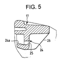
- Fig. 5 is a sectional view taken along a line V-V of Fig. 4;
- Fig. 6 is a side view showing a conventional lever-operated connector in a disconnected state;
- Fig. 7 is a side view showing the conventional lever-operated connector in a connected state;
- Figs. 8A and 8B are sectional views showing a conventional structure for locking a lever; and
- Figs. 9A to 9D are schematic side-elevational views showing the conventional lever-operated connector.
- One preferred embodiment of the present invention will now be described with reference to Figs. 1 to 5.
- Fig. 2 shows the overall construction according to the present invention. A
female connector housing 11 having (not shown) female terminals is shown on the left side of Fig. 2, and amale connector housing 12 having male terminals (not shown) and ahood portion 12a into which thefemale connector housing 11 can be inserted is shown on the right side thereof. - The
female connector housing 11 is of such a size that it can be inserted into thehood portion 12a of themale connector housing 12. A pair of cam follower pins 13 corresponding to cam follower portions (only one of which is shown) are formed on and projected laterally from opposite (right and left) sides of thefemale connector housing 11, respectively. - A pair of
guide grooves 15 is formed respectively on opposite (right and left) sides of themale connector housing 12. When thefemale connector housing 11 is fitted on the male connector housing, the cam follower pins 13 are received in theguide grooves 15, respectively. A pair of pivot pins 16 (only one of which is shown) is formed on and projected laterally from the opposite (right and left) sides of themale connector housing 12, respectively. AU-shaped lever 17 is rotatably supported on the pivot pins 16.Cam grooves 18 serving as cam portions are formed respectively so as to be hollowed out in the inner surfaces of the opposite sides of the lever 17 (on themale connector housing 12 side). When thefemale connector housing 11 is fitted, the cam follower pins 13 are received and engaged in thecam grooves 18, respectively. During the pivotal movement of thelever 17 from an open position shown in Fig. 2 to a connected position shown in Fig. 1 with the cam follower pins 13 having entered into thecam grooves 18, the cam foilower pins 13 and hence thefemale connector housing 11 are displaced toward thehood portion 12a of themale connector housing 12 by leverage. Thus, thecam grooves 18 have the function of connecting the two connector housings together with the female and male terminals connected. While not shown, in an inner surface of thelever 17 is a coil spring, which urges thelever 17 to the open position. - As shown in Fig. 2, a pair of
side walls 21 project from the upper surface of thefemale connector housing 11 so as to confront each other. Interposed between theseside walls 21 is a retainingpawl 22, which is projected through an elastic leg 23 (see Fig. 1). Hookingportions 22a are projected to the front (toward the right end portion as viewed in Fig. 1) in two positions on the retainingpawl 22. These hookingportions 22a are displaced in such a manner that the distal ends of the respective hookingportions 22a are raised with theelastic leg 23 elastically deforming in a direction of an arrow when afinger engaging portion 22b located on the rear end (on the left end portion as viewed in Fig. 1) of the retainingpawl 22 is pressed down. The lower surface of each hookingportion 22a is designed so that the distal end thereof is inclined downward. - On the other hand, a retained
portion 24 to be engaged with the retainingpawl 22 is formed in the middle of the distal end of thelever 17. The retainedportion 24 is formed integrally with thelever 17 in box-like form, with twoinclined surface portions 24a projected from the inner surfaces thereof. The respectiveinclined surface portions 24a are arranged so as to correspond to the two hookingportions 22a of the retainingpawl 22. The inclination of eachinclined surface portion 24a, being such that the front side thereof (the left side as viewed in Fig. 1) is inclined upward, fits the angle of inclination of each hookingportion 22a. As a result, a surface on which the retainedportion 24 is engaged with a retaining pawl 22 (a surface on which theinclined surface portions 24a contact the hookingportions 22a) is inclined in such a direction as to hamper retraction of the retainingpawl 22. On the rear sides of the respectiveinclined surface portions 24a are punchedholes 25. A reinforcingrib 26 is formed between the punchedholes 25 integrally with thelever 17. - According to the above-mentioned construction, when the
lever 17 is set in the connected position shown in Fig. 1, the hookingportions 22a of the retainingpawl 22 are fitted on theinclined surface portions 24a of the retainedportion 24. As a result, thelever 17 is locked in that engaged position so that its rotational movement in the open position is regulated. To release the locking of thelever 17 from this state, thefinger engaging portion 22b of the retainingpawl 22 is pressed down with a finger engaged therewith. As a result, theelastic leg 23 is elastically deformed as shown by the arrow in Fig. 1, causing the retainingpawl 22 to retract from the retainedportion 24 of thelever 17. The hookingportions 22a of the retainingpawl 22 are, in the end, disengaged from theinclined surface portions 24a of the retainedportion 24 to thereby unlock thelever 17. When thelever 17 is turned toward the open position, the cam follower pins 13 are displaced in a direction opposite to the inserting direction, when they are pressed by thecam grooves 18 in thelever 17, thereby disconnecting both connectors from each other while pushing thefemale connector housing 11 out of thehood portion 12a of themale connector housing 12. - By the way, the
lever 17 may happen to receive strong turning force toward the open position when thelever 17 is locked in the connected position for such a reason as the connectors being moved forcibly through electric wires or the like. In such a case, the retainedportion 24 of thelever 17 raises the retainingpawl 22 as is apparent from Fig. 1. However, according to this embodiment, the surface on which the retainedportion 24 is engaged with the retaining pawl 22 (the surface on which theinclined surface portions 24a contact the hookingportions 22a) is inclined in such a direction as to hamper retraction of the retainingpawl 22. Therefore, even if the retainingpawl 22 is raised, the retainingpawl 22 is not displaced easily in the retracting direction (in a direction of the arrow in Fig. 1), thereby maintaining the engagement between theinclined surface portions 24a and the hookingportions 22a. As a result, the retraction of the retainingpawl 22 from the engaged position is prevented even if a strong force is unexpectedly exerted on thelever 17 that is in the connected position toward the open position, thereby allowing thelever 17 to be locked in the connected position surely, which contributes to greatly improving the function of preventing the connectors from being disconnected from each other. - The present invention is not limited to the above embodiment, and for example the following modifications can be made:
- (a) In the above embodiment, although the lever is provided on the male connector housing while the cam follower pins are provided on the female connector housing, this may be reversed; that is, the lever may be provided on the female connector housing while the cam follower portion may be provided on the male connector housing.
- (b) In the above embodiment, although the cam follower pins (cam follower portions) are formed directly on the female connector housing, this is not always necessary.
- The present invention is not limited to the embodiment described above and shown in the drawings; but the invention may be embodied while modified in various modes within such a range as not to deviate from the material part of the invention.
Claims (2)
- A lever-operated connector comprising:a pair of connector housings (11, 12) displaced toward each other to be connected together by rotationally moving a lever (17) from an open position to a connected position;at least one pin (13) provided on one connector housing (11, 12) for engagement with at least one groove (18), said groove (18) being provided in said lever (17), which is rotatably mounted on the other connector housing (12, 11); anda lever lock portion for retaining said lever (17) in the connected position, said lever lock portion comprising:a retained portion (24) provided on said lever (17), anda retaining pawl (22) for holding said retained portion (24),characterized in thatsaid retaining pawl (22) is provided on said one connector (11, 12);and a surface (24a) on which said retained portion (24) is engaged with said retaining pawl (22) is inclined in such a direction as to hamper retraction of said retaining pawl (22).
- The connector according to claim 1, further comprising a return spring for urging said lever (17) toward said open position, and said groove (18) comprising a play region so as to allow said lever (17) to return a predetermined angle from said connected position toward said open position, wherein said lever (17) is automatically brought into an upstanding condition by the urging force of said return spring when said lever (17) is released from said lever lock portion.
Priority Applications (1)
| Application Number | Priority Date | Filing Date | Title |
|---|---|---|---|
| EP96102377A EP0727847B1 (en) | 1992-11-27 | 1993-11-25 | Lever-operated connector |
Applications Claiming Priority (4)
| Application Number | Priority Date | Filing Date | Title |
|---|---|---|---|
| JP1992087679U JP2574778Y2 (en) | 1992-11-27 | 1992-11-27 | Lever connector |
| JP87679/92 | 1992-11-27 | ||
| JP89541/92 | 1992-12-01 | ||
| JP8954192U JPH0648182U (en) | 1992-12-01 | 1992-12-01 | Lever type connector |
Related Child Applications (2)
| Application Number | Title | Priority Date | Filing Date |
|---|---|---|---|
| EP96102377A Division EP0727847B1 (en) | 1992-11-27 | 1993-11-25 | Lever-operated connector |
| EP96102377.7 Division-Into | 1996-02-16 |
Publications (2)
| Publication Number | Publication Date |
|---|---|
| EP0599332A1 EP0599332A1 (en) | 1994-06-01 |
| EP0599332B1 true EP0599332B1 (en) | 1997-03-19 |
Family
ID=26428926
Family Applications (2)
| Application Number | Title | Priority Date | Filing Date |
|---|---|---|---|
| EP93119060A Expired - Lifetime EP0599332B1 (en) | 1992-11-27 | 1993-11-25 | Lever-operated connector |
| EP96102377A Expired - Lifetime EP0727847B1 (en) | 1992-11-27 | 1993-11-25 | Lever-operated connector |
Family Applications After (1)
| Application Number | Title | Priority Date | Filing Date |
|---|---|---|---|
| EP96102377A Expired - Lifetime EP0727847B1 (en) | 1992-11-27 | 1993-11-25 | Lever-operated connector |
Country Status (3)
| Country | Link |
|---|---|
| US (1) | US5474461A (en) |
| EP (2) | EP0599332B1 (en) |
| DE (2) | DE69308993T2 (en) |
Cited By (1)
| Publication number | Priority date | Publication date | Assignee | Title |
|---|---|---|---|---|
| CN105610003A (en) * | 2014-11-17 | 2016-05-25 | 住友电装株式会社 | Lever-type connector |
Families Citing this family (38)
| Publication number | Priority date | Publication date | Assignee | Title |
|---|---|---|---|---|
| JP2882260B2 (en) * | 1993-10-04 | 1999-04-12 | 住友電装株式会社 | Lever connector |
| GB9402570D0 (en) * | 1994-02-10 | 1994-04-06 | Amp Gmbh | Electrical connector having improved latching/unlatching feature |
| JP3000129B2 (en) * | 1994-09-06 | 2000-01-17 | 矢崎総業株式会社 | Lever connector |
| JP2921647B2 (en) * | 1994-11-22 | 1999-07-19 | 矢崎総業株式会社 | Locking mechanism for low insertion / extraction connector |
| US5735702A (en) * | 1995-04-07 | 1998-04-07 | Sumitomo Wiring Systems, Ltd. | Lever type connector |
| EP1079473B1 (en) * | 1995-10-24 | 2003-03-12 | Sumitomo Wiring Systems, Ltd. | Lever type connector |
| JP3075164B2 (en) * | 1996-01-16 | 2000-08-07 | 住友電装株式会社 | Lever connector |
| US5806176A (en) * | 1996-02-05 | 1998-09-15 | Raychem Corporation | Insertion tool and method of use |
| JP3472666B2 (en) * | 1996-07-24 | 2003-12-02 | 矢崎総業株式会社 | connector |
| JP3275290B2 (en) * | 1996-08-09 | 2002-04-15 | 住友電装株式会社 | Lever connector |
| JP3468007B2 (en) * | 1997-02-05 | 2003-11-17 | 住友電装株式会社 | Lever connector |
| DE29800831U1 (en) * | 1998-01-20 | 1998-04-02 | Pft Gmbh | Horizontal mixer for mortar |
| JP3252955B2 (en) * | 1998-05-21 | 2002-02-04 | 住友電装株式会社 | Lever connector |
| US6183278B1 (en) * | 2000-01-14 | 2001-02-06 | Yazaki Corporation | Lever structure of electric connection box |
| JP4047510B2 (en) * | 2000-03-02 | 2008-02-13 | 株式会社東海理化電機製作所 | Connector device |
| GB0027758D0 (en) * | 2000-11-14 | 2000-12-27 | Delphi Tech Inc | Two-part electrical connector |
| US7070438B2 (en) * | 2004-03-31 | 2006-07-04 | Jst Corporation | Connector lever lock |
| JP4229282B2 (en) * | 2004-04-28 | 2009-02-25 | タイコエレクトロニクスアンプ株式会社 | Lever type connector |
| DE102005050625B4 (en) * | 2004-10-22 | 2011-07-28 | Sumitomo Wiring Systems, Ltd., Mie | Connector and connector assembly |
| US7255580B2 (en) * | 2005-03-09 | 2007-08-14 | Tyco Electronics Corporation | Electrical connector and electrical connector assembly having lever assist with latch hold down mechanism |
| US7261575B2 (en) * | 2005-03-09 | 2007-08-28 | Tyco Electronics Corporation | Electrical connector and electrical connector assembly having selectively includable lever assist |
| US7052294B1 (en) * | 2005-04-15 | 2006-05-30 | J.S.T. Corporation | Electrical connector with a locking mechanism |
| JP2006344473A (en) * | 2005-06-08 | 2006-12-21 | Sumitomo Wiring Syst Ltd | Lever type connector |
| JP5009538B2 (en) * | 2006-02-02 | 2012-08-22 | 矢崎総業株式会社 | Lever type connector |
| JP4791328B2 (en) * | 2006-10-27 | 2011-10-12 | 矢崎総業株式会社 | Lever type connector |
| JP5162348B2 (en) * | 2008-06-25 | 2013-03-13 | 矢崎総業株式会社 | Lever type connector |
| CN102891397B (en) * | 2012-09-19 | 2016-05-18 | 中航光电科技股份有限公司 | A kind of rectangular electric connector and assembly thereof with locking function |
| JP2016009597A (en) * | 2014-06-24 | 2016-01-18 | 日本航空電子工業株式会社 | connector |
| JP2019003916A (en) * | 2017-06-20 | 2019-01-10 | 矢崎総業株式会社 | Service plug |
| JP2019091608A (en) * | 2017-11-14 | 2019-06-13 | 住友電装株式会社 | connector |
| JP2019091610A (en) * | 2017-11-14 | 2019-06-13 | 住友電装株式会社 | connector |
| JP2019091609A (en) * | 2017-11-14 | 2019-06-13 | 住友電装株式会社 | connector |
| EP3579354B1 (en) * | 2018-06-05 | 2021-11-17 | Ningbo Geely Automobile Research & Development Co. Ltd. | A high voltage electrical connector |
| CN208797213U (en) * | 2018-06-08 | 2019-04-26 | 安费诺电子装配(厦门)有限公司 | A kind of line-end connector and connector assembly of band rotation locking bar |
| FR3084532B1 (en) * | 2018-07-27 | 2023-05-12 | Delphi Int Operations Luxembourg Sarl | CONNECTOR WITH CONNECTION ASSISTANCE LEVER AND METHOD FOR PACKAGING SUCH A CONNECTOR |
| DE102019116146A1 (en) * | 2019-06-13 | 2020-12-17 | Harting Electric Gmbh & Co. Kg | Self-locking locking bracket for a connector |
| JP2021190380A (en) * | 2020-06-03 | 2021-12-13 | タイコエレクトロニクスジャパン合同会社 | Connector and connector assembly |
| USD991025S1 (en) * | 2022-08-03 | 2023-07-04 | Kinetix Ag | Mounting device |
Family Cites Families (16)
| Publication number | Priority date | Publication date | Assignee | Title |
|---|---|---|---|---|
| DE1590736A1 (en) * | 1965-07-31 | 1970-06-25 | Tesla Np | Connector |
| DE3527916A1 (en) * | 1985-08-03 | 1987-02-12 | Cannon Electric Gmbh | ELECTRICAL CONNECTOR |
| US4634204A (en) * | 1985-12-24 | 1987-01-06 | General Motors Corporation | Electrical connector with connector position assurance/assist device |
| US4714433A (en) * | 1987-01-21 | 1987-12-22 | General Motors Corporation | Electrical connector with position assurance and double lock |
| US5135410A (en) * | 1990-05-30 | 1992-08-04 | Sumitomo Wiring Systems, Ltd. | Electric connector assembly |
| JP2525502B2 (en) * | 1990-05-30 | 1996-08-21 | 矢崎総業株式会社 | Electrical connector |
| US5139430A (en) * | 1990-06-28 | 1992-08-18 | Digital Equipment Corporation | PCB insertion/ejection lever mechanism |
| JP2971531B2 (en) * | 1990-06-29 | 1999-11-08 | 住友電装株式会社 | Connector connection structure |
| JP2501005Y2 (en) * | 1990-10-31 | 1996-06-12 | 矢崎総業株式会社 | connector |
| JP2500247Y2 (en) * | 1991-06-03 | 1996-06-05 | 矢崎総業株式会社 | Connector with lever |
| JP2538723B2 (en) * | 1991-06-25 | 1996-10-02 | 矢崎総業株式会社 | Connector with lever |
| JP2624049B2 (en) * | 1991-09-13 | 1997-06-25 | 住友電装株式会社 | connector |
| GB2260865B (en) * | 1991-10-21 | 1996-03-27 | Sumitomo Wall Systems Ltd | Lever type connector |
| JP2598412Y2 (en) * | 1992-04-03 | 1999-08-09 | 矢崎総業株式会社 | Low insertion / extraction force connector |
| JP2598090Y2 (en) * | 1992-04-28 | 1999-07-26 | 住友電装株式会社 | Lever connector |
| GB9219322D0 (en) * | 1992-09-11 | 1992-10-28 | Dzus Fastener Europe | Lever mechanism |
-
1993
- 1993-11-25 DE DE69308993T patent/DE69308993T2/en not_active Expired - Lifetime
- 1993-11-25 DE DE69320662T patent/DE69320662T2/en not_active Expired - Lifetime
- 1993-11-25 EP EP93119060A patent/EP0599332B1/en not_active Expired - Lifetime
- 1993-11-25 EP EP96102377A patent/EP0727847B1/en not_active Expired - Lifetime
- 1993-11-26 US US08/157,539 patent/US5474461A/en not_active Expired - Lifetime
Cited By (1)
| Publication number | Priority date | Publication date | Assignee | Title |
|---|---|---|---|---|
| CN105610003A (en) * | 2014-11-17 | 2016-05-25 | 住友电装株式会社 | Lever-type connector |
Also Published As
| Publication number | Publication date |
|---|---|
| DE69320662T2 (en) | 1999-02-25 |
| EP0599332A1 (en) | 1994-06-01 |
| DE69320662D1 (en) | 1998-10-01 |
| DE69308993D1 (en) | 1997-04-24 |
| EP0727847A2 (en) | 1996-08-21 |
| EP0727847B1 (en) | 1998-08-26 |
| EP0727847A3 (en) | 1997-01-08 |
| US5474461A (en) | 1995-12-12 |
| DE69308993T2 (en) | 1997-11-06 |
Similar Documents
| Publication | Publication Date | Title |
|---|---|---|
| EP0599332B1 (en) | Lever-operated connector | |
| US5938470A (en) | Half-fitting prevention connector | |
| JP3027487B2 (en) | Locking mechanism for low insertion / extraction connector | |
| EP1369964B1 (en) | Connector Position Assurance Device | |
| US5823813A (en) | Connector position assurance device | |
| CA2168399C (en) | Connector assembly for ic card | |
| KR0125801B1 (en) | Electrical connector | |
| EP0790676B1 (en) | Lever type connector | |
| EP2276123B1 (en) | Lever type connector | |
| EP1571734B1 (en) | Connector apparatus with a mating detecting member called connector position assurance | |
| EP0501502B1 (en) | Low insertion/withdrawal-force connector | |
| US20060281351A1 (en) | Lever-type connector | |
| JPH03116672A (en) | Electric connector | |
| JP3275290B2 (en) | Lever connector | |
| US6811437B2 (en) | Connector and method of mounting it | |
| US5609494A (en) | Connector lever locking mechanism | |
| EP0774802B1 (en) | Electrical connector with internal resilient member | |
| GB2398184A (en) | Card connector locking cam | |
| EP0954061B1 (en) | A connector | |
| EP1047155B1 (en) | Lever type connector | |
| EP0809203B1 (en) | Card connector capable of preventing an object and contacts from being damaged and achieving excellent reliability of connection | |
| JPH08148221A (en) | Locking mechanism of low inserting/pulling out force connector | |
| JP3938669B2 (en) | Lever type connector | |
| EP0727846B1 (en) | Lever type connector | |
| EP0883212B1 (en) | Connector engaging structure |
Legal Events
| Date | Code | Title | Description |
|---|---|---|---|
| PUAI | Public reference made under article 153(3) epc to a published international application that has entered the european phase |
Free format text: ORIGINAL CODE: 0009012 |
|
| AK | Designated contracting states |
Kind code of ref document: A1 Designated state(s): DE GB |
|
| 17P | Request for examination filed |
Effective date: 19940830 |
|
| 17Q | First examination report despatched |
Effective date: 19950310 |
|
| GRAG | Despatch of communication of intention to grant |
Free format text: ORIGINAL CODE: EPIDOS AGRA |
|
| GRAH | Despatch of communication of intention to grant a patent |
Free format text: ORIGINAL CODE: EPIDOS IGRA |
|
| GRAH | Despatch of communication of intention to grant a patent |
Free format text: ORIGINAL CODE: EPIDOS IGRA |
|
| GRAA | (expected) grant |
Free format text: ORIGINAL CODE: 0009210 |
|
| AK | Designated contracting states |
Kind code of ref document: B1 Designated state(s): DE GB |
|
| DX | Miscellaneous (deleted) | ||
| REF | Corresponds to: |
Ref document number: 69308993 Country of ref document: DE Date of ref document: 19970424 |
|
| PLBE | No opposition filed within time limit |
Free format text: ORIGINAL CODE: 0009261 |
|
| STAA | Information on the status of an ep patent application or granted ep patent |
Free format text: STATUS: NO OPPOSITION FILED WITHIN TIME LIMIT |
|
| 26N | No opposition filed | ||
| REG | Reference to a national code |
Ref country code: GB Ref legal event code: IF02 |
|
| PGFP | Annual fee paid to national office [announced via postgrant information from national office to epo] |
Ref country code: GB Payment date: 20081119 Year of fee payment: 16 |
|
| PGFP | Annual fee paid to national office [announced via postgrant information from national office to epo] |
Ref country code: DE Payment date: 20091119 Year of fee payment: 17 |
|
| GBPC | Gb: european patent ceased through non-payment of renewal fee |
Effective date: 20091125 |
|
| PG25 | Lapsed in a contracting state [announced via postgrant information from national office to epo] |
Ref country code: GB Free format text: LAPSE BECAUSE OF NON-PAYMENT OF DUE FEES Effective date: 20091125 |
|
| REG | Reference to a national code |
Ref country code: DE Ref legal event code: R119 Ref document number: 69308993 Country of ref document: DE Effective date: 20110601 Ref country code: DE Ref legal event code: R119 Ref document number: 69308993 Country of ref document: DE Effective date: 20110531 |
|
| PG25 | Lapsed in a contracting state [announced via postgrant information from national office to epo] |
Ref country code: DE Free format text: LAPSE BECAUSE OF NON-PAYMENT OF DUE FEES Effective date: 20110531 |