EP3920316A1 - Secondary battery, battery module and device - Google Patents
Secondary battery, battery module and device Download PDFInfo
- Publication number
- EP3920316A1 EP3920316A1 EP20887690.4A EP20887690A EP3920316A1 EP 3920316 A1 EP3920316 A1 EP 3920316A1 EP 20887690 A EP20887690 A EP 20887690A EP 3920316 A1 EP3920316 A1 EP 3920316A1
- Authority
- EP
- European Patent Office
- Prior art keywords
- insulation member
- metal layer
- bonding layer
- layer
- secondary battery
- Prior art date
- Legal status (The legal status is an assumption and is not a legal conclusion. Google has not performed a legal analysis and makes no representation as to the accuracy of the status listed.)
- Granted
Links
Images




Classifications
-
- H—ELECTRICITY
- H01—ELECTRIC ELEMENTS
- H01M—PROCESSES OR MEANS, e.g. BATTERIES, FOR THE DIRECT CONVERSION OF CHEMICAL ENERGY INTO ELECTRICAL ENERGY
- H01M50/00—Constructional details or processes of manufacture of the non-active parts of electrochemical cells other than fuel cells, e.g. hybrid cells
- H01M50/10—Primary casings; Jackets or wrappings
- H01M50/183—Sealing members
- H01M50/186—Sealing members characterised by the disposition of the sealing members
- H01M50/188—Sealing members characterised by the disposition of the sealing members the sealing members being arranged between the lid and terminal
-
- B—PERFORMING OPERATIONS; TRANSPORTING
- B60—VEHICLES IN GENERAL
- B60K—ARRANGEMENT OR MOUNTING OF PROPULSION UNITS OR OF TRANSMISSIONS IN VEHICLES; ARRANGEMENT OR MOUNTING OF PLURAL DIVERSE PRIME-MOVERS IN VEHICLES; AUXILIARY DRIVES FOR VEHICLES; INSTRUMENTATION OR DASHBOARDS FOR VEHICLES; ARRANGEMENTS IN CONNECTION WITH COOLING, AIR INTAKE, GAS EXHAUST OR FUEL SUPPLY OF PROPULSION UNITS IN VEHICLES
- B60K1/00—Arrangement or mounting of electrical propulsion units
- B60K1/04—Arrangement or mounting of electrical propulsion units of the electric storage means for propulsion
-
- H—ELECTRICITY
- H01—ELECTRIC ELEMENTS
- H01M—PROCESSES OR MEANS, e.g. BATTERIES, FOR THE DIRECT CONVERSION OF CHEMICAL ENERGY INTO ELECTRICAL ENERGY
- H01M50/00—Constructional details or processes of manufacture of the non-active parts of electrochemical cells other than fuel cells, e.g. hybrid cells
- H01M50/10—Primary casings; Jackets or wrappings
- H01M50/147—Lids or covers
-
- H—ELECTRICITY
- H01—ELECTRIC ELEMENTS
- H01M—PROCESSES OR MEANS, e.g. BATTERIES, FOR THE DIRECT CONVERSION OF CHEMICAL ENERGY INTO ELECTRICAL ENERGY
- H01M50/00—Constructional details or processes of manufacture of the non-active parts of electrochemical cells other than fuel cells, e.g. hybrid cells
- H01M50/10—Primary casings; Jackets or wrappings
- H01M50/147—Lids or covers
- H01M50/155—Lids or covers characterised by the material
- H01M50/157—Inorganic material
-
- H—ELECTRICITY
- H01—ELECTRIC ELEMENTS
- H01M—PROCESSES OR MEANS, e.g. BATTERIES, FOR THE DIRECT CONVERSION OF CHEMICAL ENERGY INTO ELECTRICAL ENERGY
- H01M50/00—Constructional details or processes of manufacture of the non-active parts of electrochemical cells other than fuel cells, e.g. hybrid cells
- H01M50/10—Primary casings; Jackets or wrappings
- H01M50/147—Lids or covers
- H01M50/155—Lids or covers characterised by the material
- H01M50/157—Inorganic material
- H01M50/159—Metals
-
- H—ELECTRICITY
- H01—ELECTRIC ELEMENTS
- H01M—PROCESSES OR MEANS, e.g. BATTERIES, FOR THE DIRECT CONVERSION OF CHEMICAL ENERGY INTO ELECTRICAL ENERGY
- H01M50/00—Constructional details or processes of manufacture of the non-active parts of electrochemical cells other than fuel cells, e.g. hybrid cells
- H01M50/10—Primary casings; Jackets or wrappings
- H01M50/183—Sealing members
- H01M50/19—Sealing members characterised by the material
- H01M50/197—Sealing members characterised by the material having a layered structure
-
- H—ELECTRICITY
- H01—ELECTRIC ELEMENTS
- H01M—PROCESSES OR MEANS, e.g. BATTERIES, FOR THE DIRECT CONVERSION OF CHEMICAL ENERGY INTO ELECTRICAL ENERGY
- H01M50/00—Constructional details or processes of manufacture of the non-active parts of electrochemical cells other than fuel cells, e.g. hybrid cells
- H01M50/20—Mountings; Secondary casings or frames; Racks, modules or packs; Suspension devices; Shock absorbers; Transport or carrying devices; Holders
- H01M50/204—Racks, modules or packs for multiple batteries or multiple cells
- H01M50/207—Racks, modules or packs for multiple batteries or multiple cells characterised by their shape
- H01M50/209—Racks, modules or packs for multiple batteries or multiple cells characterised by their shape adapted for prismatic or rectangular cells
-
- H—ELECTRICITY
- H01—ELECTRIC ELEMENTS
- H01M—PROCESSES OR MEANS, e.g. BATTERIES, FOR THE DIRECT CONVERSION OF CHEMICAL ENERGY INTO ELECTRICAL ENERGY
- H01M50/00—Constructional details or processes of manufacture of the non-active parts of electrochemical cells other than fuel cells, e.g. hybrid cells
- H01M50/50—Current conducting connections for cells or batteries
- H01M50/528—Fixed electrical connections, i.e. not intended for disconnection
- H01M50/529—Intercell connections through partitions, e.g. in a battery casing
-
- H—ELECTRICITY
- H01—ELECTRIC ELEMENTS
- H01M—PROCESSES OR MEANS, e.g. BATTERIES, FOR THE DIRECT CONVERSION OF CHEMICAL ENERGY INTO ELECTRICAL ENERGY
- H01M50/00—Constructional details or processes of manufacture of the non-active parts of electrochemical cells other than fuel cells, e.g. hybrid cells
- H01M50/50—Current conducting connections for cells or batteries
- H01M50/543—Terminals
-
- H—ELECTRICITY
- H01—ELECTRIC ELEMENTS
- H01M—PROCESSES OR MEANS, e.g. BATTERIES, FOR THE DIRECT CONVERSION OF CHEMICAL ENERGY INTO ELECTRICAL ENERGY
- H01M50/00—Constructional details or processes of manufacture of the non-active parts of electrochemical cells other than fuel cells, e.g. hybrid cells
- H01M50/50—Current conducting connections for cells or batteries
- H01M50/543—Terminals
- H01M50/562—Terminals characterised by the material
-
- B—PERFORMING OPERATIONS; TRANSPORTING
- B60—VEHICLES IN GENERAL
- B60K—ARRANGEMENT OR MOUNTING OF PROPULSION UNITS OR OF TRANSMISSIONS IN VEHICLES; ARRANGEMENT OR MOUNTING OF PLURAL DIVERSE PRIME-MOVERS IN VEHICLES; AUXILIARY DRIVES FOR VEHICLES; INSTRUMENTATION OR DASHBOARDS FOR VEHICLES; ARRANGEMENTS IN CONNECTION WITH COOLING, AIR INTAKE, GAS EXHAUST OR FUEL SUPPLY OF PROPULSION UNITS IN VEHICLES
- B60K1/00—Arrangement or mounting of electrical propulsion units
- B60K1/04—Arrangement or mounting of electrical propulsion units of the electric storage means for propulsion
- B60K2001/0405—Arrangement or mounting of electrical propulsion units of the electric storage means for propulsion characterised by their position
- B60K2001/0438—Arrangement under the floor
-
- H—ELECTRICITY
- H01—ELECTRIC ELEMENTS
- H01M—PROCESSES OR MEANS, e.g. BATTERIES, FOR THE DIRECT CONVERSION OF CHEMICAL ENERGY INTO ELECTRICAL ENERGY
- H01M2220/00—Batteries for particular applications
- H01M2220/20—Batteries in motive systems, e.g. vehicle, ship, plane
-
- Y—GENERAL TAGGING OF NEW TECHNOLOGICAL DEVELOPMENTS; GENERAL TAGGING OF CROSS-SECTIONAL TECHNOLOGIES SPANNING OVER SEVERAL SECTIONS OF THE IPC; TECHNICAL SUBJECTS COVERED BY FORMER USPC CROSS-REFERENCE ART COLLECTIONS [XRACs] AND DIGESTS
- Y02—TECHNOLOGIES OR APPLICATIONS FOR MITIGATION OR ADAPTATION AGAINST CLIMATE CHANGE
- Y02E—REDUCTION OF GREENHOUSE GAS [GHG] EMISSIONS, RELATED TO ENERGY GENERATION, TRANSMISSION OR DISTRIBUTION
- Y02E60/00—Enabling technologies; Technologies with a potential or indirect contribution to GHG emissions mitigation
- Y02E60/10—Energy storage using batteries
Definitions
- Embodiments of this application relate to the field of battery technologies, and in particular, to a secondary battery, a battery column, and an apparatus.
- a secondary battery includes a housing, an electrode assembly disposed in the housing, a top cover plate hermetically connected to the housing, a pole disposed on the top cover plate, an insulation member, and a current collector connecting poles and tabs of the electrode assembly.
- the poles hermetically mate with the top cover plate through the insulation member.
- sealing failure or sealing performance deterioration of the insulation member may be caused when the insulation member shifts or falls off, affecting use safety of the secondary battery.
- This application is intended to resolve a prior-art technical problem of sealing failure or sealing performance deterioration of an insulation member caused when the insulation member shifts or falls off.
- an embodiment of this application proposes a secondary battery that includes: a top cover plate, having an outer surface and an inner surface disposed opposite each other in a thickness direction of the top cover plate and an electrode lead-out hole extending along the thickness direction; a pole, disposed in the electrode lead-out hole, where the pole includes a first metal layer and a second metal layer, and the first metal layer and the second metal layer are stacked along a direction from the inner surface to the outer surface; an insulation member, disposed between the top cover plate and the pole; and a first bonding layer, disposed between the insulation member and the first metal layer, where the first metal layer and the first bonding layer are bonded by a chemical bond, the insulation member and the first bonding layer are bonded by a chemical bond, and the insulation member is hermetically connected to the first metal layer through the first bonding layer.
- the first metal layer has a first concave portion facing away from the second metal layer, part of the insulation member extends into the first concave portion, and the first bonding layer extends to between the first concave portion and the insulation member.
- the part of the insulation member extending into the first concave portion and the part of the first bonding layer extending to the first concave portion can jointly limit a position of the pole in an axial direction. This is beneficial to further reducing the possibility that the pole shifts in the axial direction when receiving stress in the axial direction.
- the secondary battery further includes a second bonding layer, the second bonding layer is disposed between the insulation member and the second metal layer, the second metal layer and the second bonding layer are bonded by a chemical bond, the insulation member and the second bonding layer are bonded by a chemical bond, and the insulation member is hermetically connected to the second metal layer through the second bonding layer.
- connection strength and sealing reliability of the insulation member and the pole are improved, reducing the possibility of sealing failure or sealing performance deterioration caused by relative displacement between the insulation member and the pole, thereby reducing the possibility that an electrolyte corrodes the second metal layer after entering between the insulation member and the second metal layer or overflows from the pole.
- the second metal layer has a second concave portion facing away from the first metal layer, part of the insulation member extends to a region close to the second concave portion, and the second bonding layer extends to between the second concave portion and the insulation member.
- the part of the insulation member extending into the second concave portion and the part of the second bonding layer extending to the second concave portion can jointly limit a position of the pole in an axial direction. This is beneficial to further reducing the possibility that the pole shifts in the axial direction when receiving stress in the axial direction.
- the second concave portion is annular, and therefore a force is uniformly applied to the pole.
- the first metal layer is a copper layer or a copper alloy layer
- the second metal layer is an aluminum layer or an aluminum alloy layer
- the first bonding layer includes a first oxide film and a triazine thiol derivative disposed on the first oxide film
- the second bonding layer includes a second oxide film and a triazine thiol derivative disposed on the second oxide film.
- the first metal layer is the copper layer or the copper alloy layer
- the second metal layer is the aluminum layer or the aluminum alloy layer
- the copper element and the triazine thiol derivative can generate a copper-sulfur chemical bond, and the triazine thiol derivative forms a covalent bond with the insulation member.
- the second metal layer is directly connected to the insulation member, tensile strength between the first metal layer and the first bonding layer is greater than tensile strength between the second metal layer and the insulation member, and tensile strength between the insulation member and the first bonding layer is greater than the tensile strength between the second metal layer and the insulation member.
- the second metal layer is welded to a current collection sheet, when an end of the second metal layer leaving the first metal layer is subject to a pulling force from the current collection sheet, the second metal layer is allowed to move slightly. However, the pulling force does not cause the first metal layer to be separated from the insulation member, thereby improving sealing reliability of the pole and the insulation member.
- the secondary battery further includes a third bonding layer, the third bonding layer is disposed between the top cover plate and the insulation member, the top cover plate and the third bonding layer are bonded by a chemical bond, the insulation member and the third bonding layer are bonded by a chemical bond, and the insulation member is hermetically connected to the top cover plate through the third bonding layer.
- top cover plate and the third bonding layer are bonded by a chemical bond, and the insulation member and the third bonding layer are bonded by a chemical bond. Therefore, tight and reliable connections are formed between the top cover plate and the third bonding layer and between the insulation member and the third bonding layer, effectively improving connection strength between the top cover plate and the insulation member, and reducing the possibility of sealing failure or sealing performance deterioration, between the top cover plate and the insulation member, caused when the insulation member shifts or falls off, thereby improving use safety of the secondary battery.
- the top cover plate is an aluminum layer or an aluminum alloy layer; and/or the first bonding layer includes a first oxide film and the triazine thiol derivative disposed on the first oxide film, and the third bonding layer includes a third oxide film and a triazine thiol derivative disposed on the third oxide film.
- the first bonding layer includes the first oxide film and the triazine thiol derivative disposed on the first oxide film. Therefore, the copper element and the triazine thiol derivative can generate a copper-sulfur chemical bond, and the triazine thiol derivative forms a covalent bond with the insulation member.
- a thickness of the first metal layer is greater than or equal to that of the second metal layer along an axial direction of the electrode lead-out hole; and/or a maximum outer diameter of the pole is less than a minimum aperture of the electrode lead-out hole.
- the maximum outer diameter of the pole is less than the minimum aperture of the electrode lead-out hole. This is beneficial to reducing a size of the pole and reducing space utilization of the pole.
- the insulation member includes a barium sulfate particle; and/or the insulation member includes a fiber structure.
- the insulation member is used to seal the top cover plate and the pole.
- At least part of an outer peripheral surface of the first metal layer is covered by the first bonding layer along the axial direction of the electrode lead-out hole; and/or the first bonding layer is 50 nanometers to 500 nanometers in thickness.
- the at least part of the outer peripheral surface of the first metal layer is covered by the first bonding layer. Therefore, this is beneficial to increasing an area of a connection region between the first metal layer and the first bonding layer, and improving connection strength and sealing reliability.
- the pole hermetically mates with the top cover plate through the first bonding layer and the insulation member.
- the first metal layer and the first bonding layer are bonded by a chemical bond
- the insulation member and the first bonding layer are bonded by a chemical bond, and therefore, tight and reliable connections are formed between the first metal layer and the first bonding layer and between the insulation member and the first bonding layer, effectively improving the connection strength between the first metal layer and the insulation member, and reducing the possibility of sealing failure or sealing performance deterioration, between the first metal layer and the insulation member, caused when the insulation member shifts or falls off, thereby improving use safety of the secondary battery.
- an embodiment of this application provides a battery column that includes the foregoing secondary battery.
- the battery column provides electrical energy to a drive motor.
- an embodiment of this application provides an apparatus using a secondary battery as a power source.
- the apparatus includes the foregoing secondary battery.
- the apparatus using a secondary battery as a power source may include, but is not limited to, a vehicle, a ship, an aircraft, or the like.
- a plurality of means two or more, orientations or position relationships indicated by the terms “up”, “down”, “left”, “right”, “inside”, “outside”, and the like are merely intended to simplify description of this application for a purpose of easy description, rather than indicate or imply that an apparatus or a part must have a particular direction or must be constructed and operated in a particular orientation. Therefore, this shall not be construed as any limitation on this application.
- the terms “first”, “second”, and the like are merely intended for a purpose of description, and shall not be understood as an indication or implication of relative importance.
- An embodiment of this application provides an apparatus using a secondary battery 20 as a power source.
- the apparatus may be, but is not limited to, a vehicle, a ship, or an aircraft.
- a vehicle that includes a vehicle body and a battery column.
- the battery column is installed in the vehicle body.
- the vehicle may be a battery electric vehicle, a hybrid vehicle, or an extended-range vehicle.
- the vehicle body is provided with a drive motor electrically connected to the battery column.
- the battery column provides electrical energy to the drive motor.
- the drive motor is connected to wheels on the vehicle body through a transmission mechanism to drive the vehicle.
- the battery column may be horizontally disposed at the bottom of the vehicle body.
- the battery column may be a battery pack 1.
- the battery pack 1 may be disposed in a plurality of ways.
- the battery pack 1 includes a box body and a battery module 10 disposed in the box body.
- the one or more battery modules 10 are arranged in the box body.
- the box body is not limited to a specific type.
- the box body may be frame-shaped, disk-shaped, or box-shaped.
- the box body may include a lower box body for accommodating the battery module 10 and an upper box body mating with the lower box body. After the lower box body is mated with the lower box body, an accommodation portion for accommodating the battery module 10 is formed. It can be understood that the battery column may also be the battery module 10.
- the battery module 10 includes a plurality of secondary batteries 20.
- the battery module 10 may be disposed in a plurality of ways.
- the battery module 10 includes an accommodation portion and the plurality of secondary batteries 20 located in the accommodation portion.
- the plurality of secondary batteries 20 are disposed side by side in the accommodation portion.
- the accommodation portion may be disposed in a plurality of ways.
- the accommodation portion includes a housing and a cover plate covering the housing; or the accommodation portion includes side plates and end plates that are successively connected to form enclosure space; or the accommodation portion includes two oppositely disposed ends plates and a strap surrounding outsides of the end plates and the secondary batteries 20.
- the secondary battery 20 in this embodiment of this application includes a housing 21, an electrode assembly 22 disposed in the housing 21, and a top cover assembly 30 hermetically connected to the housing 21.
- the housing 21 in this embodiment of this application is a square or in another shape.
- the housing 21 has internal space for accommodating the electrode assembly 22 and an electrolyte, and an opening communicating with the internal space.
- the housing 21 may be made of materials such as aluminum, aluminum alloy, or plastic.
- a body portion of the electrode assembly 22 in this embodiment of this application may be formed by stacking or winding a first electrode plate, a second electrode plate, and a separator located between the first electrode plate and the second electrode plate.
- the separator is an insulator between the first electrode plate and the second electrode plate.
- the body portion in this embodiment is of a flat structure on a whole, and has a predetermined thickness, height, and width.
- An axial direction of the body portion is a height direction of the body portion.
- the body portion has two end surfaces opposite each other in the axial direction of the body portion.
- the first electrode plate being a positive electrode plate and the second electrode plate being a negative electrode plate are used as an example for description.
- the electrode assembly 22 includes two tabs: a positive tab and a negative tab.
- the positive tab extends from the coating region of the positive plate, and the negative tab extends from the coating region of the negative plate.
- the body portion has large surfaces and small surfaces alternately disposed in a circumferential direction of the body portion.
- the top cover assembly 30 in this embodiment of this application includes a top cover plate 31, a pole 32, an insulation member 33, and a first bonding layer 34.
- the top cover plate 31 includes an outer surface 31a and an inner surface 31b disposed opposite each other in a thickness direction of the top cover plate, and an electrode lead-out hole 31c extending along the thickness direction.
- An axial direction X of the electrode lead-out hole 31c is the same as the thickness direction of the top cover plate 31.
- the pole 32 is inserted into the electrode lead-out hole 31c and hermetically mates with the top cover plate 31 through the insulation member 33 and the first bonding layer 34.
- the pole 32 includes a first metal layer 321 and a second metal layer 322.
- the first metal layer 321 and the second metal layer 322 are stacked along a direction from the inner surface 31b to the outer surface 31a of the top cover plate 31. That is, when the position shown in FIG. 6 is used as a reference, the inner surface 31b of the top cover plate 31 faces downward, and the outer surface 31a faces upward.
- the first metal layer 321 is located below the second metal layer 322.
- the first bonding layer 34 is disposed between the insulation member 33 and the first metal layer 321.
- the first metal layer 321 and the first bonding layer 34 are bonded by a chemical bond.
- the insulation member 33 and the first bonding layer 34 are bonded by a chemical bond.
- the insulation member 33 is hermetically connected to the first metal layer 321 through the first bonding layer 34.
- the pole 32 hermetically mates with the top cover plate 31 through the first bonding layer 34 and the insulation member 33.
- the first metal layer 321 and the first bonding layer 34 are bonded by a chemical bond
- the insulation member 33 and the first bonding layer 34 are bonded by a chemical bond, and therefore, tight and reliable connections are formed between the first metal layer 321 and the first bonding layer 34 and between the insulation member 33 and the first bonding layer 34, effectively improving the connection strength between the first metal layer 321 and the insulation member 33, reducing the possibility of sealing failure or sealing performance deterioration, between the first metal layer 321 and the insulation member 33, caused when the insulation member 33 shifts or falls off, and reducing the possibility that an electrolyte corrodes the first metal layer 321 after entering between the insulation member 33 and the first metal layer 321 or overflows from the pole 32, thereby improving use safety of the secondary battery using the top cover assembly 30.
- the first metal layer 321 is made of copper or copper alloy.
- the first metal layer 321 is made of a material same as that of a negative electrode adapting piece or a negative tab. This is beneficial to welding of the first metal layer 321 and the negative electrode adapting piece or the first metal layer 321 and the tab.
- the first metal layer 321 is subject to triazine treatment to form a triazine thiolate copper salt film on a surface of the first metal layer 321, and then the first metal layer 321 is treated with a superoxide solution composed of hydrogen peroxide, potassium peroxide, sodium peroxide, and hydroperoxide, to form a first oxide film containing copper oxide, thereby forming the first bonding layer 34 including the first oxide film and a triazine thiol derivative.
- the copper element and the triazine thiol derivative can generate a copper (Cu)-sulfur (S) chemical bond, and the triazine thiol derivative forms a covalent bond with the insulation member 33.
- the first metal layer 321 is combined with an injected thermoplastic material under high temperature and high pressure to form an integrated structure.
- the injected thermoplastic material finally forms the insulation member 33.
- the integral structure herein means that the first metal layer 321 and the insulation member 33 cannot be detached after being combined, and the two are connected to form an integral structure.
- the insulation member 33 may be made of a thermoplastic material such as polyphenylene sulfide or polybutylene terephthalate.
- a thickness D of the first bonding layer 34 is 50 nanometers to 500 nanometers, and in some embodiments, the thickness D of the first bonding layer 34 is 80 nanometers to 300 nanometers.
- the thickness D of the first bonding layer 34 is a thickness value in a direction leaving the first metal layer 321.
- a thickness of the first metal layer 321 is greater than or equal to that of the second metal layer 322 along the axial direction X of the electrode lead-out hole 31c. This is beneficial to further increasing the area of the connection region between the first metal layer 321, the first bonding layer 34, and the insulation member 33, and improving the connection strength and sealing reliability.
- a maximum outer diameter of the pole 32 is less than a minimum aperture of the electrode lead-out hole 31c.
- orthographic projection of the pole 32 falls inside orthographic projection of a hole wall of the electrode lead-out hole 31c. This is beneficial to reducing a size of the pole 32 and reducing space utilization of the pole 32.
- the pole 32 transmits the stress to the top cover plate 31 through the first bonding layer 34 and the insulation member 33.
- the first bonding layer 34 is disposed between the insulation member 33 and the first metal layer 321.
- the insulation member 33 may be made of a thermoplastic material such as polyphenylene sulfide or polybutylene terephthalate.
- the insulation member 33 further includes a barium sulfate particle.
- the barium sulfate particles can help improve structural strength of the insulation member 33, so that the insulation member 33 itself has high tensile resistance.
- a particle size of the barium sulfate particle is 0.1 micrometer to 4 micrometers.
- the insulation member 33 includes a fiber structure.
- the fiber structure can help improve structural strength of the insulation member 33, so that the insulation member 33 itself has high tensile resistance.
- a length of the fiber structure is 40 to 220 microns.
- the fiber structure may be a carbon fiber or a glass fiber.
- the first metal layer 321 has a first concave portion 321a facing away from the second metal layer 322.
- the first concave portion 321a has a first axially extending surface 321aa and a first radially extending surface 321ab that intersect with each other.
- Part of the insulation member 33 extends into the first concave portion 321a.
- the first bonding layer 34 extends to between the first concave portion 321a and the insulation member 33.
- the part of the insulation member 33 extending into the first concave portion 321a and the part of the first bonding layer 34 extending to the first concave portion 321a can jointly limit a position of the pole 32 in the axial direction.
- the first concave portion 321a penetrates through the outer peripheral surface of the first metal layer 321.
- the first concave portion 321a extends along a circumferential direction of the pole 32.
- the top cover assembly 30 further includes a second bonding layer 35.
- the second bonding layer 35 is disposed between the insulation member 33 and the second metal layer 322.
- the second metal layer 322 and the second bonding layer 35 are bonded by a chemical bond.
- the insulation member 33 and the second bonding layer 35 are bonded by a chemical bond.
- the insulation member 33 is hermetically connected to the second metal layer 322 through the second bonding layer 35. In this way, the insulation member 33 is hermetically connected to the first metal layer 321 through the first bonding layer 34, and is hermetically connected to the second metal layer 322 through the second bonding layer 35.
- connection strength and sealing reliability of the insulation member 33 and the pole 32 are further improved, reducing the possibility of sealing failure or sealing performance deterioration caused by relative displacement between the insulation member 33 and the pole 32, thereby reducing the possibility that an electrolyte corrodes the second metal layer 322 after entering between the insulation member 33 and the second metal layer 322 or overflows from the pole 32.
- the second metal layer 322 is made of aluminum or aluminum alloy.
- the second metal layer 322 is made of a material same as that of a current collection sheet 40. This is beneficial to welding of the second metal layer 322 and the current collection sheet 40.
- the second metal layer 322 is subject to oxidization to form a second oxide film on a surface of the second metal layer 322, and then is subject to triazine treatment to form a triazine thiol derivative inside or on a surface of the second oxide film, thereby forming the second bonding layer 35 including the second oxide film and the triazine thiol derivative.
- the insulation member 33 may be made of a thermoplastic material such as polyphenylene sulfide or polybutylene terephthalate.
- the first metal layer 321 is made of copper or copper alloy.
- the second metal layer 322 is made of aluminum or aluminum alloy.
- the first metal layer 321 and the second metal layer 322 are compositely connected through a composite process.
- a thickness of the second bonding layer 35 is 50 nanometers to 500 nanometers, and in some embodiments, the thickness of the second bonding layer 35 is 80 nanometers to 300 nanometers.
- the second metal layer 322 has a second concave portion 322a facing away from the first metal layer 321.
- the second concave portion 322a has a second axially extending surface 322aa and a second radially extending surface 322ab that intersect with each other.
- Part of the insulation member 33 extends into the second concave portion 322a.
- the second bonding layer 35 extends to between the second concave portion 322a and the insulation member 33.
- the part of the insulation member 33 extending into the second concave portion 322a and the part of the second bonding layer 35 extending to the second concave portion 322a can jointly limit a position of the pole 32 in an axial direction.
- the second concave portion 322a penetrates through the outer peripheral surface of the second metal layer 322.
- the second concave portion 322a extends along a circumferential direction of the pole 32.
- the two first concave portions 321a are spaced apart along a circumferential direction of the pole 32.
- the second metal layer 322 has a third concave portion 322b facing away from the first metal layer 321.
- the third concave portion 322b has a third axially extending surface 322ba and a third radially extending surface 322bb connected to the second concave portion 322a.
- the insulation member 33 does not protrude from the third radially extending surface 322bb.
- the current collection sheet 40 is not in contact with the insulation member 33, thereby reducing the possibility that the insulation member 33 deforms and sealing performance is affected because the current collection sheet 40 is in contact with and squeezes the insulation member 33.
- the insulation member 33 is connected to the first metal layer 321 through the first bonding layer 34, and the insulation member 33 hermetically mates with the first bonding layer 34, and the first bonding layer 34 hermetically mates with the first metal layer 321.
- the second metal layer 322 is directly connected to the insulation member 33, tensile strength between the first metal layer 321 and the first bonding layer 34 is greater than tensile strength between the second metal layer 322 and the insulation member 33, and tensile strength between the insulation member 33 and the first bonding layer 34 is greater than the tensile strength between the second metal layer 322 and the insulation member 33.
- the second metal layer 322 is welded to a current collection sheet 37, when an end of the second metal layer 322 leaving the first metal layer 321 is subject to a pulling force from the current collection sheet 37, the second metal layer 322 is allowed to move slightly. However, the pulling force does not cause the first metal layer 321 to be separated from the insulation member 33, thereby improving sealing reliability of the pole 32 and the insulation member 33.
- the top cover assembly 30 further includes a third bonding layer 36.
- the third bonding layer 36 is disposed between the top cover plate 31 and the insulation member 33.
- the top cover plate 31 and the third bonding layer 36 are bonded by a chemical bond.
- the insulation member 33 and the third bonding layer 36 are bonded by a chemical bond.
- the insulation member 33 is hermetically connected to the top cover plate 31 through the third bonding layer 36.
- the top cover plate 31 and the third bonding layer 36 are bonded by a chemical bond, and the insulation member 33 and the third bonding layer 36 are bonded by a chemical bond.
- the top cover plate 31 is made of aluminum or aluminum alloy.
- the top cover plate 31 is subject to oxidization to form a third oxide film on a surface of the top cover plate 31, and then is subject to triazine treatment to form a triazine thiol derivative inside or on a surface of the third oxide film, thereby forming the third bonding layer 36 including the third oxide film and the triazine thiol derivative.
- the aluminum element and the triazine thiol derivative generate an Al-S chemical bond, and the triazine thiol derivative forms a covalent bond with the insulation member 33.
- the top cover plate 31 is combined with an injected thermoplastic material under high temperature and high pressure to form an integrated structure.
- the injected thermoplastic material finally forms the insulation member 33.
- the insulation member 33 may be made of a thermoplastic material such as polyphenylene sulfide or polybutylene terephthalate.
- the top cover plate 31 is made of copper or copper alloy.
- the top cover plate 31 is subject to triazine treatment to form a triazine thiolate copper salt film on a surface of the top cover plate 31, and then the top cover plate 31 is treated with a superoxide solution composed of hydrogen peroxide, potassium peroxide, sodium peroxide, and hydroperoxide, to form a third oxide film containing copper oxide, thereby forming the third bonding layer 36 including the third oxide film and a triazine thiol derivative.
- the copper element and the triazine thiol derivative can generate a Cu-S chemical bond, and the triazine thiol derivative forms a covalent bond with the insulation member 33.
- the top cover plate 31 is combined with an injected thermoplastic material under high temperature and high pressure to form an integrated structure.
- the injected thermoplastic material finally forms the insulation member 33.
- the integral structure herein means that the top cover plate 31 and the insulation member 33 cannot be detached after being combined, and the two are connected to form an integral structure.
- the insulation member 33 may be made of a thermoplastic material such as polyphenylene sulfide or polybutylene terephthalate.
- the top cover assembly 30 further includes an insulation plate 37.
- the insulation plate 37 is disposed below the top cover plate 31.
- the insulation plate 37 has a through hole corresponding to the electrode lead-out hole 31c.
- the insulation plate 37 is used to press the electrode assembly 22 to reduce the possibility of the electrode assembly 22 moving in the housing 21.
- the insulation plate 37 may be made of rubber or plastic.
- the secondary battery 20 in this embodiment of this application includes the top cover plate 31, the pole 32, the first bonding layer 34, and the insulation member 33.
- the insulation member 33 is used to seal the top cover plate 31 and the pole 32.
- the insulation member 33 is connected and fastened to the first metal layer 321 through the first bonding layer 34, the insulation member 33 and the first bonding layer 34 are bonded by a chemical bond, and the first metal layer 321 and the first bonding layer 34 are also bonded by a chemical bond, effectively improving connection strength and sealing reliability of the first metal layer 321 and the insulation member 33, reducing the possibility of sealing failure or sealing performance deterioration caused by relative displacement between the insulation member 33 and the pole 32, and then reducing the possibility that an electrolyte corrodes the first metal layer 321 after entering between the insulation member 33 and the first metal layer 321 or overflows from the pole 32, thereby improving safety of the secondary battery 20.
Landscapes
- Chemical & Material Sciences (AREA)
- Chemical Kinetics & Catalysis (AREA)
- Electrochemistry (AREA)
- General Chemical & Material Sciences (AREA)
- Engineering & Computer Science (AREA)
- Inorganic Chemistry (AREA)
- Combustion & Propulsion (AREA)
- Transportation (AREA)
- Mechanical Engineering (AREA)
- Connection Of Batteries Or Terminals (AREA)
- Sealing Battery Cases Or Jackets (AREA)
Abstract
Description
- This application claims priority to
Chinese Patent Application No. 201921982166.2, filed to the China National Intellectual Property Administration on November 15, 2019 - Embodiments of this application relate to the field of battery technologies, and in particular, to a secondary battery, a battery column, and an apparatus.
- Secondary batteries have been widely used in the fields of hybrid vehicles and electric vehicles due to their advantages such as high energy, high capacity, and high power. A secondary battery includes a housing, an electrode assembly disposed in the housing, a top cover plate hermetically connected to the housing, a pole disposed on the top cover plate, an insulation member, and a current collector connecting poles and tabs of the electrode assembly. The poles hermetically mate with the top cover plate through the insulation member. However, during use of the secondary battery, sealing failure or sealing performance deterioration of the insulation member may be caused when the insulation member shifts or falls off, affecting use safety of the secondary battery.
- This application is intended to resolve a prior-art technical problem of sealing failure or sealing performance deterioration of an insulation member caused when the insulation member shifts or falls off.
- According to an aspect, an embodiment of this application proposes a secondary battery that includes:
a top cover plate, having an outer surface and an inner surface disposed opposite each other in a thickness direction of the top cover plate and an electrode lead-out hole extending along the thickness direction; a pole, disposed in the electrode lead-out hole, where the pole includes a first metal layer and a second metal layer, and the first metal layer and the second metal layer are stacked along a direction from the inner surface to the outer surface; an insulation member, disposed between the top cover plate and the pole; and a first bonding layer, disposed between the insulation member and the first metal layer, where the first metal layer and the first bonding layer are bonded by a chemical bond, the insulation member and the first bonding layer are bonded by a chemical bond, and the insulation member is hermetically connected to the first metal layer through the first bonding layer. - Therefore, tight and reliable connections are formed between the first metal layer and the first bonding layer and between the insulation member and the first bonding layer, effectively improving connection strength between the first metal layer and the insulation member, and reducing the possibility of sealing failure or sealing performance deterioration, between the first metal layer and the insulation member, caused when the insulation member shifts or falls off, thereby improving use safety of the secondary battery.
- According to an aspect of the embodiments of this application, the first metal layer has a first concave portion facing away from the second metal layer, part of the insulation member extends into the first concave portion, and the first bonding layer extends to between the first concave portion and the insulation member. There is only one annular first concave portion, or there are two or more first concave portions, and the two or more first concave portions are spaced apart along a circumferential direction of the pole.
- Therefore, the part of the insulation member extending into the first concave portion and the part of the first bonding layer extending to the first concave portion can jointly limit a position of the pole in an axial direction. This is beneficial to further reducing the possibility that the pole shifts in the axial direction when receiving stress in the axial direction.
- According to an aspect of the embodiments of this application, the secondary battery further includes a second bonding layer, the second bonding layer is disposed between the insulation member and the second metal layer, the second metal layer and the second bonding layer are bonded by a chemical bond, the insulation member and the second bonding layer are bonded by a chemical bond, and the insulation member is hermetically connected to the second metal layer through the second bonding layer.
- Therefore, overall connection strength and sealing reliability of the insulation member and the pole are improved, reducing the possibility of sealing failure or sealing performance deterioration caused by relative displacement between the insulation member and the pole, thereby reducing the possibility that an electrolyte corrodes the second metal layer after entering between the insulation member and the second metal layer or overflows from the pole.
- According to an aspect of the embodiments of this application, the second metal layer has a second concave portion facing away from the first metal layer, part of the insulation member extends to a region close to the second concave portion, and the second bonding layer extends to between the second concave portion and the insulation member.
- Therefore, the part of the insulation member extending into the second concave portion and the part of the second bonding layer extending to the second concave portion can jointly limit a position of the pole in an axial direction. This is beneficial to further reducing the possibility that the pole shifts in the axial direction when receiving stress in the axial direction.
- According to an aspect of the embodiments of this application, there is only one annular second concave portion, or there are two or more second concave portions, and the two or more second concave portions are spaced apart along the circumferential direction of the pole.
- The second concave portion is annular, and therefore a force is uniformly applied to the pole.
- According to an aspect of the embodiments of this application, the first metal layer is a copper layer or a copper alloy layer, and the second metal layer is an aluminum layer or an aluminum alloy layer; and/or
the first bonding layer includes a first oxide film and a triazine thiol derivative disposed on the first oxide film, and the second bonding layer includes a second oxide film and a triazine thiol derivative disposed on the second oxide film. - Therefore, when the first metal layer is the copper layer or the copper alloy layer, and the second metal layer is the aluminum layer or the aluminum alloy layer, it is beneficial to welding of the first metal layer and a negative electrode adapting piece, or the first metal layer and tabs. The copper element and the triazine thiol derivative can generate a copper-sulfur chemical bond, and the triazine thiol derivative forms a covalent bond with the insulation member.
- According to an aspect of the embodiments of this application, the second metal layer is directly connected to the insulation member, tensile strength between the first metal layer and the first bonding layer is greater than tensile strength between the second metal layer and the insulation member, and tensile strength between the insulation member and the first bonding layer is greater than the tensile strength between the second metal layer and the insulation member.
- Therefore, after the second metal layer is welded to a current collection sheet, when an end of the second metal layer leaving the first metal layer is subject to a pulling force from the current collection sheet, the second metal layer is allowed to move slightly. However, the pulling force does not cause the first metal layer to be separated from the insulation member, thereby improving sealing reliability of the pole and the insulation member.
- According to an aspect of the embodiments of this application, the secondary battery further includes a third bonding layer, the third bonding layer is disposed between the top cover plate and the insulation member, the top cover plate and the third bonding layer are bonded by a chemical bond, the insulation member and the third bonding layer are bonded by a chemical bond, and the insulation member is hermetically connected to the top cover plate through the third bonding layer.
- The top cover plate and the third bonding layer are bonded by a chemical bond, and the insulation member and the third bonding layer are bonded by a chemical bond. Therefore, tight and reliable connections are formed between the top cover plate and the third bonding layer and between the insulation member and the third bonding layer, effectively improving connection strength between the top cover plate and the insulation member, and reducing the possibility of sealing failure or sealing performance deterioration, between the top cover plate and the insulation member, caused when the insulation member shifts or falls off, thereby improving use safety of the secondary battery.
- According to an aspect of the embodiments of this application, the top cover plate is an aluminum layer or an aluminum alloy layer; and/or the first bonding layer includes a first oxide film and the triazine thiol derivative disposed on the first oxide film, and the third bonding layer includes a third oxide film and a triazine thiol derivative disposed on the third oxide film.
- The first bonding layer includes the first oxide film and the triazine thiol derivative disposed on the first oxide film. Therefore, the copper element and the triazine thiol derivative can generate a copper-sulfur chemical bond, and the triazine thiol derivative forms a covalent bond with the insulation member.
- According to an aspect of the embodiments of this application, a thickness of the first metal layer is greater than or equal to that of the second metal layer along an axial direction of the electrode lead-out hole; and/or
a maximum outer diameter of the pole is less than a minimum aperture of the electrode lead-out hole. - The maximum outer diameter of the pole is less than the minimum aperture of the electrode lead-out hole. This is beneficial to reducing a size of the pole and reducing space utilization of the pole.
- According to an aspect of the embodiments of this application, the insulation member includes a barium sulfate particle; and/or the insulation member includes a fiber structure.
- The insulation member is used to seal the top cover plate and the pole.
- According to an aspect of the embodiments of this application, at least part of an outer peripheral surface of the first metal layer is covered by the first bonding layer along the axial direction of the electrode lead-out hole; and/or the first bonding layer is 50 nanometers to 500 nanometers in thickness.
- The at least part of the outer peripheral surface of the first metal layer is covered by the first bonding layer. Therefore, this is beneficial to increasing an area of a connection region between the first metal layer and the first bonding layer, and improving connection strength and sealing reliability.
- According to the secondary battery in this embodiment of this application, the pole hermetically mates with the top cover plate through the first bonding layer and the insulation member. The first metal layer and the first bonding layer are bonded by a chemical bond, the insulation member and the first bonding layer are bonded by a chemical bond, and therefore, tight and reliable connections are formed between the first metal layer and the first bonding layer and between the insulation member and the first bonding layer, effectively improving the connection strength between the first metal layer and the insulation member, and reducing the possibility of sealing failure or sealing performance deterioration, between the first metal layer and the insulation member, caused when the insulation member shifts or falls off, thereby improving use safety of the secondary battery.
- According to another aspect, an embodiment of this application provides a battery column that includes the foregoing secondary battery.
- The battery column provides electrical energy to a drive motor.
- According to another aspect, an embodiment of this application provides an apparatus using a secondary battery as a power source. The apparatus includes the foregoing secondary battery.
- The apparatus using a secondary battery as a power source according to this embodiment of this application may include, but is not limited to, a vehicle, a ship, an aircraft, or the like.
- To describe the technical solutions in the embodiments of this application or in the prior art more clearly, the following briefly describes the accompanying drawings for describing the embodiments or the prior art. Apparently, the accompanying drawings in the following description show some embodiments of this application, and a person of ordinary skill in the art may still derive other drawings from these accompanying drawings without creative efforts.
- The features, advantages, and technical effects of example embodiments of this application are described below with reference to the accompanying drawings.
-
FIG. 1 is a schematic structural diagram of a vehicle according to an embodiment of this application; -
FIG. 2 is a schematic exploded view of a battery pack according to an embodiment of this application; -
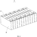
FIG. 3 is a schematic structural diagram of a battery module according to an embodiment of this application; -
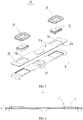
FIG. 4 is a schematic exploded view of a secondary battery according to an embodiment of this application; -
FIG. 5 is a schematic exploded view of a top cover assembly according to an embodiment of this application; -
FIG. 6 is a schematic structural cross-sectional view of a top cover assembly according to an embodiment of this application; -
FIG. 7 is an enlarged view of A inFIG. 6 ; and -
FIG. 8 is a partial schematic structural cross-sectional view of a top cover assembly according to another embodiment of this application; - In the drawings, the drawings may not be drawn to an actual scale.
- Reference signs:
- 1. battery pack;
- 10. battery module;
- 20. secondary battery; 21. housing; 22. electrode assembly;
- 30. top cover assembly; 31. top cover plate; 31a. outer surface; 31b. inner surface; 31c. electrode lead-out hole; 32. pole; 321. first metal layer; 321a. first concave portion; 321aa. first axially extending surface; 321ab. first radially extending surface; 322. second metal layer; 322a. second concave portion; 322aa. second axially extending surface; 322ab. second radially extending surface; 322b. third concave portion; 322ba. third axially extending surface; 322bb. third radially extending surface; 33. insulation member; 34. first bonding layer; 35. second bonding layer; 36. third bonding layer; 37. insulation plate;
- 40. current collection sheet; and
- X. axial direction.
- The following describes embodiments of this application in further details with reference to the accompanying drawings and embodiments. The detailed description of the following embodiments and drawings are used to exemplarily illustrate principles of this application, but cannot be used to limit the scope of this application, that is, this application is not limited to the described embodiments.
- In the descriptions of this application, it should be noted that unless otherwise stated, "a plurality of" means two or more, orientations or position relationships indicated by the terms "up", "down", "left", "right", "inside", "outside", and the like are merely intended to simplify description of this application for a purpose of easy description, rather than indicate or imply that an apparatus or a part must have a particular direction or must be constructed and operated in a particular orientation. Therefore, this shall not be construed as any limitation on this application. In addition, the terms "first", "second", and the like are merely intended for a purpose of description, and shall not be understood as an indication or implication of relative importance.
- In the descriptions of this application, it should be further noted that unless otherwise specified and defined explicitly, the terms "mounted", "interconnected", and "connected" are to be interpreted broadly, for example, being fixedly connected, or detachably connected, or integrally connected, or directly connected, or indirectly connected through an intermediate medium. A person of ordinary skill in the art can understand specific meanings of these terms in this application based on specific situations.
- For better understanding of this application, the following describes the embodiments of this application with reference to
FIG. 1 to FIG. 8 . - An embodiment of this application provides an apparatus using a
secondary battery 20 as a power source. The apparatus may be, but is not limited to, a vehicle, a ship, or an aircraft. Referring toFIG. 1 , an embodiment of this application provides a vehicle that includes a vehicle body and a battery column. The battery column is installed in the vehicle body. The vehicle may be a battery electric vehicle, a hybrid vehicle, or an extended-range vehicle. The vehicle body is provided with a drive motor electrically connected to the battery column. The battery column provides electrical energy to the drive motor. The drive motor is connected to wheels on the vehicle body through a transmission mechanism to drive the vehicle. In some embodiments, the battery column may be horizontally disposed at the bottom of the vehicle body. - As shown in
FIG. 2 , the battery column may be abattery pack 1. Thebattery pack 1 may be disposed in a plurality of ways. In some embodiments, thebattery pack 1 includes a box body and abattery module 10 disposed in the box body. There are one ormore battery modules 10. The one ormore battery modules 10 are arranged in the box body. The box body is not limited to a specific type. The box body may be frame-shaped, disk-shaped, or box-shaped. In some embodiments, the box body may include a lower box body for accommodating thebattery module 10 and an upper box body mating with the lower box body. After the lower box body is mated with the lower box body, an accommodation portion for accommodating thebattery module 10 is formed. It can be understood that the battery column may also be thebattery module 10. - Referring to
FIG. 3 , thebattery module 10 includes a plurality ofsecondary batteries 20. Thebattery module 10 may be disposed in a plurality of ways. In an embodiment, thebattery module 10 includes an accommodation portion and the plurality ofsecondary batteries 20 located in the accommodation portion. The plurality ofsecondary batteries 20 are disposed side by side in the accommodation portion. The accommodation portion may be disposed in a plurality of ways. For example, the accommodation portion includes a housing and a cover plate covering the housing; or the accommodation portion includes side plates and end plates that are successively connected to form enclosure space; or the accommodation portion includes two oppositely disposed ends plates and a strap surrounding outsides of the end plates and thesecondary batteries 20. - Referring to
FIG. 4 , thesecondary battery 20 in this embodiment of this application includes ahousing 21, anelectrode assembly 22 disposed in thehousing 21, and atop cover assembly 30 hermetically connected to thehousing 21. - The
housing 21 in this embodiment of this application is a square or in another shape. Thehousing 21 has internal space for accommodating theelectrode assembly 22 and an electrolyte, and an opening communicating with the internal space. Thehousing 21 may be made of materials such as aluminum, aluminum alloy, or plastic. - A body portion of the
electrode assembly 22 in this embodiment of this application may be formed by stacking or winding a first electrode plate, a second electrode plate, and a separator located between the first electrode plate and the second electrode plate. The separator is an insulator between the first electrode plate and the second electrode plate. The body portion in this embodiment is of a flat structure on a whole, and has a predetermined thickness, height, and width. An axial direction of the body portion is a height direction of the body portion. The body portion has two end surfaces opposite each other in the axial direction of the body portion. In this embodiment, the first electrode plate being a positive electrode plate and the second electrode plate being a negative electrode plate are used as an example for description. An active material for the positive electrode plate is applied on a coating region of the positive electrode plate, and an active material for the negative electrode plate is applied on a coating region of the negative electrode plate. Uncoated regions extending from the coating regions of the body portion serve as tabs. Theelectrode assembly 22 includes two tabs: a positive tab and a negative tab. The positive tab extends from the coating region of the positive plate, and the negative tab extends from the coating region of the negative plate. The body portion has large surfaces and small surfaces alternately disposed in a circumferential direction of the body portion. - Referring to
FIG. 5 to FIG. 7 , thetop cover assembly 30 in this embodiment of this application includes atop cover plate 31, apole 32, aninsulation member 33, and afirst bonding layer 34. Thetop cover plate 31 includes anouter surface 31a and aninner surface 31b disposed opposite each other in a thickness direction of the top cover plate, and an electrode lead-outhole 31c extending along the thickness direction. An axial direction X of the electrode lead-outhole 31c is the same as the thickness direction of thetop cover plate 31. Thepole 32 is inserted into the electrode lead-outhole 31c and hermetically mates with thetop cover plate 31 through theinsulation member 33 and thefirst bonding layer 34. Thepole 32 includes afirst metal layer 321 and asecond metal layer 322. Thefirst metal layer 321 and thesecond metal layer 322 are stacked along a direction from theinner surface 31b to theouter surface 31a of thetop cover plate 31. That is, when the position shown inFIG. 6 is used as a reference, theinner surface 31b of thetop cover plate 31 faces downward, and theouter surface 31a faces upward. Thefirst metal layer 321 is located below thesecond metal layer 322. Thefirst bonding layer 34 is disposed between theinsulation member 33 and thefirst metal layer 321. Thefirst metal layer 321 and thefirst bonding layer 34 are bonded by a chemical bond. Theinsulation member 33 and thefirst bonding layer 34 are bonded by a chemical bond. Theinsulation member 33 is hermetically connected to thefirst metal layer 321 through thefirst bonding layer 34. - According to the
secondary battery 20 in this embodiment of this application, thepole 32 hermetically mates with thetop cover plate 31 through thefirst bonding layer 34 and theinsulation member 33. Thefirst metal layer 321 and thefirst bonding layer 34 are bonded by a chemical bond, theinsulation member 33 and thefirst bonding layer 34 are bonded by a chemical bond, and therefore, tight and reliable connections are formed between thefirst metal layer 321 and thefirst bonding layer 34 and between theinsulation member 33 and thefirst bonding layer 34, effectively improving the connection strength between thefirst metal layer 321 and theinsulation member 33, reducing the possibility of sealing failure or sealing performance deterioration, between thefirst metal layer 321 and theinsulation member 33, caused when theinsulation member 33 shifts or falls off, and reducing the possibility that an electrolyte corrodes thefirst metal layer 321 after entering between theinsulation member 33 and thefirst metal layer 321 or overflows from thepole 32, thereby improving use safety of the secondary battery using thetop cover assembly 30. - In an embodiment, the
first metal layer 321 is made of copper or copper alloy. When thepole 32 is used as a negative electrode, thefirst metal layer 321 is made of a material same as that of a negative electrode adapting piece or a negative tab. This is beneficial to welding of thefirst metal layer 321 and the negative electrode adapting piece or thefirst metal layer 321 and the tab. First, thefirst metal layer 321 is subject to triazine treatment to form a triazine thiolate copper salt film on a surface of thefirst metal layer 321, and then thefirst metal layer 321 is treated with a superoxide solution composed of hydrogen peroxide, potassium peroxide, sodium peroxide, and hydroperoxide, to form a first oxide film containing copper oxide, thereby forming thefirst bonding layer 34 including the first oxide film and a triazine thiol derivative. The copper element and the triazine thiol derivative can generate a copper (Cu)-sulfur (S) chemical bond, and the triazine thiol derivative forms a covalent bond with theinsulation member 33. Finally, thefirst metal layer 321 is combined with an injected thermoplastic material under high temperature and high pressure to form an integrated structure. The injected thermoplastic material finally forms theinsulation member 33. The integral structure herein means that thefirst metal layer 321 and theinsulation member 33 cannot be detached after being combined, and the two are connected to form an integral structure. In some embodiments, theinsulation member 33 may be made of a thermoplastic material such as polyphenylene sulfide or polybutylene terephthalate. - In an embodiment, as shown in
FIG. 7 , at least part of an outer peripheral surface of thefirst metal layer 321 is covered by thefirst bonding layer 34 along the axial direction X of the electrode lead-outhole 31c. In some embodiments, an entire outer peripheral surface of thefirst metal layer 321 is covered by thefirst bonding layer 34. This is beneficial to increasing an area of a connection region between thefirst metal layer 321, thefirst bonding layer 34, and theinsulation member 33, and improving connection strength and sealing reliability. In an example, a thickness D of thefirst bonding layer 34 is 50 nanometers to 500 nanometers, and in some embodiments, the thickness D of thefirst bonding layer 34 is 80 nanometers to 300 nanometers. The thickness D of thefirst bonding layer 34 is a thickness value in a direction leaving thefirst metal layer 321. - In an embodiment, a thickness of the
first metal layer 321 is greater than or equal to that of thesecond metal layer 322 along the axial direction X of the electrode lead-outhole 31c. This is beneficial to further increasing the area of the connection region between thefirst metal layer 321, thefirst bonding layer 34, and theinsulation member 33, and improving the connection strength and sealing reliability. - In an embodiment, a maximum outer diameter of the
pole 32 is less than a minimum aperture of the electrode lead-outhole 31c. Along the axial direction X of the electrode lead-outhole 31c, orthographic projection of thepole 32 falls inside orthographic projection of a hole wall of the electrode lead-outhole 31c. This is beneficial to reducing a size of thepole 32 and reducing space utilization of thepole 32. When thepole 32 itself receives external stress in the axial direction, thepole 32 transmits the stress to thetop cover plate 31 through thefirst bonding layer 34 and theinsulation member 33. Thefirst bonding layer 34 is disposed between theinsulation member 33 and thefirst metal layer 321. This indirectly enhances connection strength between theinsulation member 33 and thefirst metal layer 321, thereby reducing the possibility of sealing failure or sealing performance deterioration, between thefirst metal layer 321 and theinsulation member 33, caused by separation or falling loose of thefirst metal layer 321 and theinsulation member 33 when thepole 32 itself receives external stress in the axial direction. - In an embodiment, the
insulation member 33 may be made of a thermoplastic material such as polyphenylene sulfide or polybutylene terephthalate. In an example, theinsulation member 33 further includes a barium sulfate particle. The barium sulfate particles can help improve structural strength of theinsulation member 33, so that theinsulation member 33 itself has high tensile resistance. In some embodiments, a particle size of the barium sulfate particle is 0.1 micrometer to 4 micrometers. In another example, theinsulation member 33 includes a fiber structure. The fiber structure can help improve structural strength of theinsulation member 33, so that theinsulation member 33 itself has high tensile resistance. In some embodiments, a length of the fiber structure is 40 to 220 microns. The fiber structure may be a carbon fiber or a glass fiber. - In an embodiment, referring to
FIG. 7 , thefirst metal layer 321 has a firstconcave portion 321a facing away from thesecond metal layer 322. The firstconcave portion 321a has a first axially extending surface 321aa and a first radially extending surface 321ab that intersect with each other. Part of theinsulation member 33 extends into the firstconcave portion 321a. Thefirst bonding layer 34 extends to between the firstconcave portion 321a and theinsulation member 33. The part of theinsulation member 33 extending into the firstconcave portion 321a and the part of thefirst bonding layer 34 extending to the firstconcave portion 321a can jointly limit a position of thepole 32 in the axial direction. This is beneficial to further reducing the possibility that thepole 32 shifts in the axial direction when receiving stress in the axial direction. In an example, the firstconcave portion 321a penetrates through the outer peripheral surface of thefirst metal layer 321. In an example, there is one annular firstconcave portion 321a. The firstconcave portion 321a extends along a circumferential direction of thepole 32. In another example, there are two or more firstconcave portions 321a. The two firstconcave portions 321a are spaced apart along a circumferential direction of thepole 32. - In an embodiment, referring to
FIG. 8 , thetop cover assembly 30 further includes asecond bonding layer 35. Thesecond bonding layer 35 is disposed between theinsulation member 33 and thesecond metal layer 322. Thesecond metal layer 322 and thesecond bonding layer 35 are bonded by a chemical bond. Theinsulation member 33 and thesecond bonding layer 35 are bonded by a chemical bond. Theinsulation member 33 is hermetically connected to thesecond metal layer 322 through thesecond bonding layer 35. In this way, theinsulation member 33 is hermetically connected to thefirst metal layer 321 through thefirst bonding layer 34, and is hermetically connected to thesecond metal layer 322 through thesecond bonding layer 35. Therefore, overall connection strength and sealing reliability of theinsulation member 33 and thepole 32 are further improved, reducing the possibility of sealing failure or sealing performance deterioration caused by relative displacement between theinsulation member 33 and thepole 32, thereby reducing the possibility that an electrolyte corrodes thesecond metal layer 322 after entering between theinsulation member 33 and thesecond metal layer 322 or overflows from thepole 32. - In an embodiment, the
second metal layer 322 is made of aluminum or aluminum alloy. When thepole 32 is used as a negative electrode, thesecond metal layer 322 is made of a material same as that of acurrent collection sheet 40. This is beneficial to welding of thesecond metal layer 322 and thecurrent collection sheet 40. First, thesecond metal layer 322 is subject to oxidization to form a second oxide film on a surface of thesecond metal layer 322, and then is subject to triazine treatment to form a triazine thiol derivative inside or on a surface of the second oxide film, thereby forming thesecond bonding layer 35 including the second oxide film and the triazine thiol derivative. The aluminum element and the triazine thiol derivative can generate an Al-S chemical bond, and the triazine thiol derivative forms a covalent bond with theinsulation member 33. Finally, thesecond metal layer 322 is combined with an injected thermoplastic material under high temperature and high pressure to form an integrated structure. The injected thermoplastic material finally forms theinsulation member 33. In some embodiments, theinsulation member 33 may be made of a thermoplastic material such as polyphenylene sulfide or polybutylene terephthalate. - In an embodiment, the
first metal layer 321 is made of copper or copper alloy. thesecond metal layer 322 is made of aluminum or aluminum alloy. Thefirst metal layer 321 and thesecond metal layer 322 are compositely connected through a composite process. - In an embodiment, at least part of an outer peripheral surface of the
second metal layer 322 is covered by thesecond bonding layer 35 along the axial direction X of the electrode lead-outhole 31c. In some embodiments, an entire outer peripheral surface of thesecond metal layer 322 is covered by thesecond bonding layer 35. This is beneficial to increasing an area of a connection region between thesecond metal layer 322, thesecond bonding layer 35, and theinsulation member 33, and improving connection strength and sealing reliability. In an example, a thickness of thesecond bonding layer 35 is 50 nanometers to 500 nanometers, and in some embodiments, the thickness of thesecond bonding layer 35 is 80 nanometers to 300 nanometers. - In an embodiment, referring to
FIG. 8 , thesecond metal layer 322 has a secondconcave portion 322a facing away from thefirst metal layer 321. The secondconcave portion 322a has a second axially extending surface 322aa and a second radially extending surface 322ab that intersect with each other. Part of theinsulation member 33 extends into the secondconcave portion 322a. Thesecond bonding layer 35 extends to between the secondconcave portion 322a and theinsulation member 33. The part of theinsulation member 33 extending into the secondconcave portion 322a and the part of thesecond bonding layer 35 extending to the secondconcave portion 322a can jointly limit a position of thepole 32 in an axial direction. This is beneficial to further reducing the possibility that thepole 32 shifts in the axial direction when receiving stress in the axial direction. In an example, the secondconcave portion 322a penetrates through the outer peripheral surface of thesecond metal layer 322. In an example, there is one annular secondconcave portion 322a. The secondconcave portion 322a extends along a circumferential direction of thepole 32. In another example, there are two or more secondconcave portions 322a. The two firstconcave portions 321a are spaced apart along a circumferential direction of thepole 32. - In an embodiment, referring to
FIG. 8 , thesecond metal layer 322 has a thirdconcave portion 322b facing away from thefirst metal layer 321. The thirdconcave portion 322b has a third axially extending surface 322ba and a third radially extending surface 322bb connected to the secondconcave portion 322a. In the axial direction X of the electrode lead-outhole 31c, theinsulation member 33 does not protrude from the third radially extending surface 322bb. When twosecondary batteries 20 are connected in series or in parallel by acurrent collection sheet 40, thecurrent collection sheet 40 is welded to an end surface of thesecond metal layer 322 leaving thefirst metal layer 321. Because thesecond metal layer 322 has the third concave portionedportion 322b, thecurrent collection sheet 40 is not in contact with theinsulation member 33, thereby reducing the possibility that theinsulation member 33 deforms and sealing performance is affected because thecurrent collection sheet 40 is in contact with and squeezes theinsulation member 33. - In an embodiment, the
insulation member 33 is connected to thefirst metal layer 321 through thefirst bonding layer 34, and theinsulation member 33 hermetically mates with thefirst bonding layer 34, and thefirst bonding layer 34 hermetically mates with thefirst metal layer 321. Thesecond metal layer 322 is directly connected to theinsulation member 33, tensile strength between thefirst metal layer 321 and thefirst bonding layer 34 is greater than tensile strength between thesecond metal layer 322 and theinsulation member 33, and tensile strength between theinsulation member 33 and thefirst bonding layer 34 is greater than the tensile strength between thesecond metal layer 322 and theinsulation member 33. Therefore, after thesecond metal layer 322 is welded to acurrent collection sheet 37, when an end of thesecond metal layer 322 leaving thefirst metal layer 321 is subject to a pulling force from thecurrent collection sheet 37, thesecond metal layer 322 is allowed to move slightly. However, the pulling force does not cause thefirst metal layer 321 to be separated from theinsulation member 33, thereby improving sealing reliability of thepole 32 and theinsulation member 33. - In an embodiment, referring to
FIG. 7 andFIG. 8 , thetop cover assembly 30 further includes athird bonding layer 36. Thethird bonding layer 36 is disposed between thetop cover plate 31 and theinsulation member 33. Thetop cover plate 31 and thethird bonding layer 36 are bonded by a chemical bond. Theinsulation member 33 and thethird bonding layer 36 are bonded by a chemical bond. Theinsulation member 33 is hermetically connected to thetop cover plate 31 through thethird bonding layer 36. Thetop cover plate 31 and thethird bonding layer 36 are bonded by a chemical bond, and theinsulation member 33 and thethird bonding layer 36 are bonded by a chemical bond. Therefore, tight and reliable connections are formed between thetop cover plate 31 and thethird bonding layer 36 and between theinsulation member 33 and thethird bonding layer 36, effectively improving connection strength between thetop cover plate 31 and theinsulation member 33, and reducing the possibility of sealing failure or sealing performance deterioration, between thetop cover plate 31 and theinsulation member 33, caused when theinsulation member 33 shifts or falls off, thereby improving use safety of thesecondary battery 20. - In an embodiment, the
top cover plate 31 is made of aluminum or aluminum alloy. First, thetop cover plate 31 is subject to oxidization to form a third oxide film on a surface of thetop cover plate 31, and then is subject to triazine treatment to form a triazine thiol derivative inside or on a surface of the third oxide film, thereby forming thethird bonding layer 36 including the third oxide film and the triazine thiol derivative. The aluminum element and the triazine thiol derivative generate an Al-S chemical bond, and the triazine thiol derivative forms a covalent bond with theinsulation member 33. Finally, thetop cover plate 31 is combined with an injected thermoplastic material under high temperature and high pressure to form an integrated structure. The injected thermoplastic material finally forms theinsulation member 33. In some embodiments, theinsulation member 33 may be made of a thermoplastic material such as polyphenylene sulfide or polybutylene terephthalate. - In an embodiment, the
top cover plate 31 is made of copper or copper alloy. First, thetop cover plate 31 is subject to triazine treatment to form a triazine thiolate copper salt film on a surface of thetop cover plate 31, and then thetop cover plate 31 is treated with a superoxide solution composed of hydrogen peroxide, potassium peroxide, sodium peroxide, and hydroperoxide, to form a third oxide film containing copper oxide, thereby forming thethird bonding layer 36 including the third oxide film and a triazine thiol derivative. The copper element and the triazine thiol derivative can generate a Cu-S chemical bond, and the triazine thiol derivative forms a covalent bond with theinsulation member 33. Finally, thetop cover plate 31 is combined with an injected thermoplastic material under high temperature and high pressure to form an integrated structure. The injected thermoplastic material finally forms theinsulation member 33. The integral structure herein means that thetop cover plate 31 and theinsulation member 33 cannot be detached after being combined, and the two are connected to form an integral structure. In some embodiments, theinsulation member 33 may be made of a thermoplastic material such as polyphenylene sulfide or polybutylene terephthalate. - In an embodiment, the
top cover assembly 30 further includes aninsulation plate 37. Theinsulation plate 37 is disposed below thetop cover plate 31. Theinsulation plate 37 has a through hole corresponding to the electrode lead-outhole 31c. Theinsulation plate 37 is used to press theelectrode assembly 22 to reduce the possibility of theelectrode assembly 22 moving in thehousing 21. In some embodiments, theinsulation plate 37 may be made of rubber or plastic. - The
secondary battery 20 in this embodiment of this application includes thetop cover plate 31, thepole 32, thefirst bonding layer 34, and theinsulation member 33. Theinsulation member 33 is used to seal thetop cover plate 31 and thepole 32. Theinsulation member 33 is connected and fastened to thefirst metal layer 321 through thefirst bonding layer 34, theinsulation member 33 and thefirst bonding layer 34 are bonded by a chemical bond, and thefirst metal layer 321 and thefirst bonding layer 34 are also bonded by a chemical bond, effectively improving connection strength and sealing reliability of thefirst metal layer 321 and theinsulation member 33, reducing the possibility of sealing failure or sealing performance deterioration caused by relative displacement between theinsulation member 33 and thepole 32, and then reducing the possibility that an electrolyte corrodes thefirst metal layer 321 after entering between theinsulation member 33 and thefirst metal layer 321 or overflows from thepole 32, thereby improving safety of thesecondary battery 20. - Although this application has been described with reference to some embodiments, various improvements can be made to this application and equivalents can be substituted for the components therein without departing from the scope of this application. In particular, the technical features in the embodiments can be combined in any manner provided that there is no structural conflict. This application is not limited to the specific embodiments disclosed herein, but includes all technical solutions falling within the scope of the claims.
Claims (15)
- A secondary battery comprising:a top cover plate having an outer surface and an inner surface disposed opposite each other in a thickness direction of the top cover plate and an electrode lead-out hole extending along the thickness direction;a pole disposed in the electrode lead-out hole wherein the pole comprises a first metal layer and a second metal layer and the first metal layer and the second metal layer are stacked along a direction from the inner surface to the outer surfacean insulation member disposed between the top cover plate and the pole anda first bonding layer disposed between the insulation member and the first metal layer wherein the first metal layer and the first bonding layer are bonded by a chemical bond, the insulation member and the first bonding layer are bonded by a chemical bond, and the insulation member is hermetically connected to the first metal layer through the first bonding layer
- The secondary battery according to claim 1, wherein the first metal layer has a first concave portion facing away from the second metal layer part of the insulation member extends into the first concave portion and the first bonding layer extends to between the first concave portion and the insulation member
- The secondary battery according to claim 2, wherein there is only one annular first concave portion or there are two or more first concave portions and the two or more first concave portions are spaced apart along a circumferential direction of the pole
- The secondary battery according to any one of claims 1 to 3, wherein the secondary battery further comprises a second bonding layer the second bonding layer is disposed between the insulation member and the second metal layer the second metal layer and the second bonding layer are bonded by a chemical bond, the insulation member and the second bonding layer are bonded by a chemical bond, and the insulation member is hermetically connected to the second metal layer through the second bonding layer
- The secondary battery according to claim 4, wherein the second metal layer has a second concave portion facing away from the first metal layer part of the insulation member extends to a region close to the second concave portion and the second bonding layer extends to between the second concave portion and the insulation member
- The secondary battery according to claim 5, wherein there is only one annular second concave portion or there are two or more second concave portions and the two or more second concave portions are spaced apart along the circumferential direction of the pole
- The secondary battery according to any one of claims 4 to 6, characterized in thatthe first metal layer is a copper layer or a copper alloy layer, and the second metal layer is an aluminum layer or an aluminum alloy layer; and/orthe first bonding layer comprises a first oxide film and a triazine thiol derivative disposed on the first oxide film, and the second bonding layer comprises a second oxide film and a triazine thiol derivative disposed on the second oxide film.
- The secondary battery according to any one of claims 1 to 7, wherein the second metal layer is directly connected to the insulation member tensile strength between the first metal layer and the first bonding layer is greater than tensile strength between the second metal layer and the insulation member and tensile strength between the insulation member and the first bonding layer is greater than the tensile strength between the second metal layer and the insulation member
- The secondary battery according to any one of claims 1 to 8, wherein the secondary battery further comprises a third bonding layer the third bonding layer is disposed between the top cover plate and the insulation member the top cover plate and the third bonding layer are bonded by a chemical bond, the insulation member and the third bonding layer are bonded by a chemical bond, and the insulation member is hermetically connected to the top cover plate through the third bonding layer
- The secondary battery according to claim 9, characterized in that
the top cover plate is an aluminum layer or an aluminum alloy layer; and/or the first bonding layer comprises the first oxide film and the triazine thiol derivative disposed on the first oxide film, and the third bonding layer comprises a third oxide film and a triazine thiol derivative disposed on the third oxide film. - The secondary battery according to any one of claims 1 to 10, characterized in thata thickness of the first metal layer is greater than or equal to that of the second metal layer along an axial direction of the electrode lead-out hole and/ora maximum outer diameter of the pole is less than a minimum aperture of the electrode lead-out hole
- The secondary battery according to any one of claims 1 to 11, wherein the insulation member comprises barium sulfate particles; and/or the insulation member comprises a fiber structure.
- The secondary battery according to any one of claims 1 to 12, wherein at least part of an outer peripheral surface of the first metal layer is covered by the first bonding layer along the axial direction of the electrode lead-out hole and/or the first bonding layer is 50 nanometers to 500 nanometers in thickness.
- A battery column, comprising the secondary battery according to any one of claims 1 to 13.
- An apparatus using a secondary battery as a power source, comprising the secondary battery according to any one of claims 1 to 13.
Applications Claiming Priority (2)
| Application Number | Priority Date | Filing Date | Title |
|---|---|---|---|
| CN201921982166.2U CN211017169U (en) | 2019-11-15 | 2019-11-15 | Secondary battery, battery module, and device |
| PCT/CN2020/127908 WO2021093747A1 (en) | 2019-11-15 | 2020-11-10 | Secondary battery, battery module and device |
Publications (3)
| Publication Number | Publication Date |
|---|---|
| EP3920316A1 true EP3920316A1 (en) | 2021-12-08 |
| EP3920316A4 EP3920316A4 (en) | 2022-06-08 |
| EP3920316B1 EP3920316B1 (en) | 2023-07-26 |
Family
ID=71479127
Family Applications (1)
| Application Number | Title | Priority Date | Filing Date |
|---|---|---|---|
| EP20887690.4A Active EP3920316B1 (en) | 2019-11-15 | 2020-11-10 | Secondary battery, battery module and device |
Country Status (7)
| Country | Link |
|---|---|
| US (1) | US11894568B2 (en) |
| EP (1) | EP3920316B1 (en) |
| JP (1) | JP7416934B2 (en) |
| KR (1) | KR102616024B1 (en) |
| CN (1) | CN211017169U (en) |
| HU (1) | HUE062764T2 (en) |
| WO (1) | WO2021093747A1 (en) |
Families Citing this family (6)
| Publication number | Priority date | Publication date | Assignee | Title |
|---|---|---|---|---|
| CN211017169U (en) * | 2019-11-15 | 2020-07-14 | 宁德时代新能源科技股份有限公司 | Secondary battery, battery module, and device |
| CN113394493A (en) * | 2021-06-25 | 2021-09-14 | 银隆新能源股份有限公司 | Lithium ion battery and electric vehicle with same |
| US20250087844A1 (en) * | 2022-09-08 | 2025-03-13 | Lg Energy Solution, Ltd. | Busbar With Improved Flame Resistance and Battery Pack Including the Same |
| KR102872698B1 (en) * | 2022-09-08 | 2025-10-20 | 주식회사 엘지에너지솔루션 | Busbar with improved flame resistance and battery pack comprising the same |
| JP1775610S (en) * | 2023-03-03 | 2024-07-17 | Battery, Electric | |
| JP1778256S (en) * | 2023-08-23 | 2024-08-21 | Battery, Electric |
Family Cites Families (19)
| Publication number | Priority date | Publication date | Assignee | Title |
|---|---|---|---|---|
| JP2008027849A (en) | 2006-07-25 | 2008-02-07 | Denso Corp | Seal member |
| JP5182838B2 (en) * | 2006-07-25 | 2013-04-17 | 株式会社デンソー | Sealing plate for lithium battery container, manufacturing method thereof and lithium battery |
| WO2009078382A1 (en) | 2007-12-14 | 2009-06-25 | Denso Corporation | Resin-metal bonded article and method for producing the same |
| JP5265293B2 (en) | 2008-10-06 | 2013-08-14 | トヨタ自動車株式会社 | SEALING MATERIAL, SEAL FOR SECONDARY BATTERY MOLDED BY USING SAME, AND SECONDARY BATTERY HAVING THE SAME |
| JP5945904B2 (en) | 2010-12-28 | 2016-07-05 | 株式会社Gsユアサ | Method for manufacturing power storage element |
| KR101222286B1 (en) * | 2011-01-13 | 2013-01-15 | 로베르트 보쉬 게엠베하 | Secondary battery |
| JP6014837B2 (en) * | 2011-03-30 | 2016-10-26 | 日立金属株式会社 | Negative electrode terminal and lid member for lithium ion battery, and lithium ion battery |
| JP5482965B2 (en) | 2011-05-25 | 2014-05-07 | トヨタ自動車株式会社 | battery |
| JP2014038819A (en) | 2012-07-19 | 2014-02-27 | Mutsuki Denki Kk | Junction inspection method of sealing body for sealed electrochemical device |
| WO2015030137A1 (en) | 2013-08-30 | 2015-03-05 | Dic株式会社 | Resin composition for gasket, production method therefor, and gasket for secondary battery |
| TW201809176A (en) * | 2016-04-07 | 2018-03-16 | 日商東芝股份有限公司 | Semiconductor package and method of manufacturing same |
| KR102283783B1 (en) * | 2016-09-21 | 2021-07-30 | 삼성에스디아이 주식회사 | Rechargeable battery |
| CN107658394A (en) * | 2017-08-22 | 2018-02-02 | 深圳市长盈精密技术股份有限公司 | A kind of electrokinetic cell, cover plate of power battery and its manufacture method |
| JP2019091656A (en) | 2017-11-16 | 2019-06-13 | リチウム エナジー アンド パワー ゲゼルシャフト ミット ベシュレンクテル ハフッング ウント コンパニー コマンディトゲゼルシャフトLithium Energy and Power GmbH & Co. KG | Power storage element and power storage device |
| JP2019160746A (en) | 2018-03-16 | 2019-09-19 | 株式会社東芝 | Sealing body for lithium ion secondary battery, manufacturing method thereof, and lithium ion secondary battery |
| CN209056523U (en) * | 2018-11-07 | 2019-07-02 | 宁德时代新能源科技股份有限公司 | Secondary battery |
| CN111106299A (en) | 2018-11-07 | 2020-05-05 | 宁德时代新能源科技股份有限公司 | Secondary battery and method for manufacturing same |
| CN209447920U (en) * | 2019-03-13 | 2019-09-27 | 宁德时代新能源科技股份有限公司 | Secondary cell |
| CN211017169U (en) * | 2019-11-15 | 2020-07-14 | 宁德时代新能源科技股份有限公司 | Secondary battery, battery module, and device |
-
2019
- 2019-11-15 CN CN201921982166.2U patent/CN211017169U/en active Active
-
2020
- 2020-11-10 WO PCT/CN2020/127908 patent/WO2021093747A1/en not_active Ceased
- 2020-11-10 KR KR1020227015309A patent/KR102616024B1/en active Active
- 2020-11-10 EP EP20887690.4A patent/EP3920316B1/en active Active
- 2020-11-10 HU HUE20887690A patent/HUE062764T2/en unknown
- 2020-11-10 JP JP2022526449A patent/JP7416934B2/en active Active
-
2021
- 2021-08-31 US US17/462,741 patent/US11894568B2/en active Active
Also Published As
| Publication number | Publication date |
|---|---|
| WO2021093747A1 (en) | 2021-05-20 |
| JP2023501440A (en) | 2023-01-18 |
| JP7416934B2 (en) | 2024-01-17 |
| CN211017169U (en) | 2020-07-14 |
| HUE062764T2 (en) | 2023-12-28 |
| KR102616024B1 (en) | 2023-12-19 |
| EP3920316A4 (en) | 2022-06-08 |
| KR20220076515A (en) | 2022-06-08 |
| US11894568B2 (en) | 2024-02-06 |
| US20210399372A1 (en) | 2021-12-23 |
| EP3920316B1 (en) | 2023-07-26 |
Similar Documents
| Publication | Publication Date | Title |
|---|---|---|
| US11894568B2 (en) | Secondary battery, battery column, and apparatus | |
| US12266825B2 (en) | Secondary battery, battery module, and power consuming device | |
| US20210143505A1 (en) | Energy storage apparatus | |
| EP4071923A1 (en) | Battery cell, battery, electric device, and method and system for fabricating battery cell | |
| US11929510B2 (en) | Secondary battery and manufacturing method thereof, battery module, and apparatus | |
| US20210328313A1 (en) | End cover assembly, battery cell, battery module and device | |
| EP4632895A1 (en) | Battery cell, battery, and electric apparatus | |
| JP2023044777A (en) | battery | |
| CN210467900U (en) | Battery cells, battery modules, battery packs and devices | |
| US20240322391A1 (en) | Power storage module | |
| US20230084184A1 (en) | Energy storage apparatus | |
| CN210984767U (en) | Top cover assembly, secondary battery, battery module, battery pack and device | |
| US20220158306A1 (en) | Power storage device | |
| US12224456B2 (en) | Connection component, battery cell, battery and electrical device | |
| CN118117222A (en) | Power storage device | |
| CN114566769A (en) | Electrochemical device, battery module, and electric device | |
| JP2023070239A (en) | battery case and battery | |
| EP4187664A1 (en) | Battery | |
| US20250391968A1 (en) | Battery cell, battery and electrical apparatus | |
| EP4693656A1 (en) | Power storage module | |
| KR20240054179A (en) | Battery | |
| KR20260014469A (en) | Battery, battery pack and vehicle including the same | |
| CN118117221A (en) | Power storage device | |
| KR20160127559A (en) | Electrode lead and battery module for high capacity comprising the same |
Legal Events
| Date | Code | Title | Description |
|---|---|---|---|
| STAA | Information on the status of an ep patent application or granted ep patent |
Free format text: STATUS: THE INTERNATIONAL PUBLICATION HAS BEEN MADE |
|
| PUAI | Public reference made under article 153(3) epc to a published international application that has entered the european phase |
Free format text: ORIGINAL CODE: 0009012 |
|
| STAA | Information on the status of an ep patent application or granted ep patent |
Free format text: STATUS: REQUEST FOR EXAMINATION WAS MADE |
|
| 17P | Request for examination filed |
Effective date: 20210830 |
|
| AK | Designated contracting states |
Kind code of ref document: A1 Designated state(s): AL AT BE BG CH CY CZ DE DK EE ES FI FR GB GR HR HU IE IS IT LI LT LU LV MC MK MT NL NO PL PT RO RS SE SI SK SM TR |
|
| REG | Reference to a national code |
Ref country code: DE Ref legal event code: R079 Free format text: PREVIOUS MAIN CLASS: H01M0050147000 Ipc: H01M0050529000 Ref document number: 602020014670 Country of ref document: DE |
|
| A4 | Supplementary search report drawn up and despatched |
Effective date: 20220510 |
|
| RIC1 | Information provided on ipc code assigned before grant |
Ipc: B60K 1/04 20190101ALI20220503BHEP Ipc: H01M 50/562 20210101ALI20220503BHEP Ipc: H01M 50/197 20210101ALI20220503BHEP Ipc: H01M 50/188 20210101ALI20220503BHEP Ipc: H01M 50/159 20210101ALI20220503BHEP Ipc: H01M 50/157 20210101ALI20220503BHEP Ipc: H01M 50/529 20210101AFI20220503BHEP |
|
| STAA | Information on the status of an ep patent application or granted ep patent |
Free format text: STATUS: EXAMINATION IS IN PROGRESS |
|
| 17Q | First examination report despatched |
Effective date: 20221004 |
|
| DAV | Request for validation of the european patent (deleted) | ||
| DAX | Request for extension of the european patent (deleted) | ||
| GRAP | Despatch of communication of intention to grant a patent |
Free format text: ORIGINAL CODE: EPIDOSNIGR1 |
|
| STAA | Information on the status of an ep patent application or granted ep patent |
Free format text: STATUS: GRANT OF PATENT IS INTENDED |
|
| INTG | Intention to grant announced |
Effective date: 20230428 |
|
| GRAS | Grant fee paid |
Free format text: ORIGINAL CODE: EPIDOSNIGR3 |
|
| GRAA | (expected) grant |
Free format text: ORIGINAL CODE: 0009210 |
|
| STAA | Information on the status of an ep patent application or granted ep patent |
Free format text: STATUS: THE PATENT HAS BEEN GRANTED |
|
| AK | Designated contracting states |
Kind code of ref document: B1 Designated state(s): AL AT BE BG CH CY CZ DE DK EE ES FI FR GB GR HR HU IE IS IT LI LT LU LV MC MK MT NL NO PL PT RO RS SE SI SK SM TR |
|
| RAP3 | Party data changed (applicant data changed or rights of an application transferred) |
Owner name: CONTEMPORARY AMPEREX TECHNOLOGY CO., LIMITED |
|
| REG | Reference to a national code |
Ref country code: CH Ref legal event code: EP |
|
| REG | Reference to a national code |
Ref country code: DE Ref legal event code: R096 Ref document number: 602020014670 Country of ref document: DE |
|
| REG | Reference to a national code |
Ref country code: IE Ref legal event code: FG4D |
|
| P01 | Opt-out of the competence of the unified patent court (upc) registered |
Effective date: 20230908 |
|
| REG | Reference to a national code |
Ref country code: LT Ref legal event code: MG9D |
|
| REG | Reference to a national code |
Ref country code: NL Ref legal event code: MP Effective date: 20230726 |
|
| REG | Reference to a national code |
Ref country code: AT Ref legal event code: MK05 Ref document number: 1593007 Country of ref document: AT Kind code of ref document: T Effective date: 20230726 |
|
| REG | Reference to a national code |
Ref country code: HU Ref legal event code: AG4A Ref document number: E062764 Country of ref document: HU |
|
| PG25 | Lapsed in a contracting state [announced via postgrant information from national office to epo] |
Ref country code: NL Free format text: LAPSE BECAUSE OF FAILURE TO SUBMIT A TRANSLATION OF THE DESCRIPTION OR TO PAY THE FEE WITHIN THE PRESCRIBED TIME-LIMIT Effective date: 20230726 |
|
| PG25 | Lapsed in a contracting state [announced via postgrant information from national office to epo] |
Ref country code: GR Free format text: LAPSE BECAUSE OF FAILURE TO SUBMIT A TRANSLATION OF THE DESCRIPTION OR TO PAY THE FEE WITHIN THE PRESCRIBED TIME-LIMIT Effective date: 20231027 |
|
| PG25 | Lapsed in a contracting state [announced via postgrant information from national office to epo] |
Ref country code: IS Free format text: LAPSE BECAUSE OF FAILURE TO SUBMIT A TRANSLATION OF THE DESCRIPTION OR TO PAY THE FEE WITHIN THE PRESCRIBED TIME-LIMIT Effective date: 20231126 |
|
| PG25 | Lapsed in a contracting state [announced via postgrant information from national office to epo] |
Ref country code: SE Free format text: LAPSE BECAUSE OF FAILURE TO SUBMIT A TRANSLATION OF THE DESCRIPTION OR TO PAY THE FEE WITHIN THE PRESCRIBED TIME-LIMIT Effective date: 20230726 Ref country code: RS Free format text: LAPSE BECAUSE OF FAILURE TO SUBMIT A TRANSLATION OF THE DESCRIPTION OR TO PAY THE FEE WITHIN THE PRESCRIBED TIME-LIMIT Effective date: 20230726 Ref country code: PT Free format text: LAPSE BECAUSE OF FAILURE TO SUBMIT A TRANSLATION OF THE DESCRIPTION OR TO PAY THE FEE WITHIN THE PRESCRIBED TIME-LIMIT Effective date: 20231127 Ref country code: NO Free format text: LAPSE BECAUSE OF FAILURE TO SUBMIT A TRANSLATION OF THE DESCRIPTION OR TO PAY THE FEE WITHIN THE PRESCRIBED TIME-LIMIT Effective date: 20231026 Ref country code: LV Free format text: LAPSE BECAUSE OF FAILURE TO SUBMIT A TRANSLATION OF THE DESCRIPTION OR TO PAY THE FEE WITHIN THE PRESCRIBED TIME-LIMIT Effective date: 20230726 Ref country code: LT Free format text: LAPSE BECAUSE OF FAILURE TO SUBMIT A TRANSLATION OF THE DESCRIPTION OR TO PAY THE FEE WITHIN THE PRESCRIBED TIME-LIMIT Effective date: 20230726 Ref country code: IS Free format text: LAPSE BECAUSE OF FAILURE TO SUBMIT A TRANSLATION OF THE DESCRIPTION OR TO PAY THE FEE WITHIN THE PRESCRIBED TIME-LIMIT Effective date: 20231126 Ref country code: HR Free format text: LAPSE BECAUSE OF FAILURE TO SUBMIT A TRANSLATION OF THE DESCRIPTION OR TO PAY THE FEE WITHIN THE PRESCRIBED TIME-LIMIT Effective date: 20230726 Ref country code: GR Free format text: LAPSE BECAUSE OF FAILURE TO SUBMIT A TRANSLATION OF THE DESCRIPTION OR TO PAY THE FEE WITHIN THE PRESCRIBED TIME-LIMIT Effective date: 20231027 Ref country code: FI Free format text: LAPSE BECAUSE OF FAILURE TO SUBMIT A TRANSLATION OF THE DESCRIPTION OR TO PAY THE FEE WITHIN THE PRESCRIBED TIME-LIMIT Effective date: 20230726 Ref country code: AT Free format text: LAPSE BECAUSE OF FAILURE TO SUBMIT A TRANSLATION OF THE DESCRIPTION OR TO PAY THE FEE WITHIN THE PRESCRIBED TIME-LIMIT Effective date: 20230726 |
|
| PG25 | Lapsed in a contracting state [announced via postgrant information from national office to epo] |
Ref country code: PL Free format text: LAPSE BECAUSE OF FAILURE TO SUBMIT A TRANSLATION OF THE DESCRIPTION OR TO PAY THE FEE WITHIN THE PRESCRIBED TIME-LIMIT Effective date: 20230726 |
|
| PG25 | Lapsed in a contracting state [announced via postgrant information from national office to epo] |
Ref country code: ES Free format text: LAPSE BECAUSE OF FAILURE TO SUBMIT A TRANSLATION OF THE DESCRIPTION OR TO PAY THE FEE WITHIN THE PRESCRIBED TIME-LIMIT Effective date: 20230726 |
|
| REG | Reference to a national code |
Ref country code: DE Ref legal event code: R097 Ref document number: 602020014670 Country of ref document: DE |
|
| PG25 | Lapsed in a contracting state [announced via postgrant information from national office to epo] |
Ref country code: SM Free format text: LAPSE BECAUSE OF FAILURE TO SUBMIT A TRANSLATION OF THE DESCRIPTION OR TO PAY THE FEE WITHIN THE PRESCRIBED TIME-LIMIT Effective date: 20230726 Ref country code: RO Free format text: LAPSE BECAUSE OF FAILURE TO SUBMIT A TRANSLATION OF THE DESCRIPTION OR TO PAY THE FEE WITHIN THE PRESCRIBED TIME-LIMIT Effective date: 20230726 Ref country code: ES Free format text: LAPSE BECAUSE OF FAILURE TO SUBMIT A TRANSLATION OF THE DESCRIPTION OR TO PAY THE FEE WITHIN THE PRESCRIBED TIME-LIMIT Effective date: 20230726 Ref country code: EE Free format text: LAPSE BECAUSE OF FAILURE TO SUBMIT A TRANSLATION OF THE DESCRIPTION OR TO PAY THE FEE WITHIN THE PRESCRIBED TIME-LIMIT Effective date: 20230726 Ref country code: DK Free format text: LAPSE BECAUSE OF FAILURE TO SUBMIT A TRANSLATION OF THE DESCRIPTION OR TO PAY THE FEE WITHIN THE PRESCRIBED TIME-LIMIT Effective date: 20230726 Ref country code: CZ Free format text: LAPSE BECAUSE OF FAILURE TO SUBMIT A TRANSLATION OF THE DESCRIPTION OR TO PAY THE FEE WITHIN THE PRESCRIBED TIME-LIMIT Effective date: 20230726 Ref country code: SK Free format text: LAPSE BECAUSE OF FAILURE TO SUBMIT A TRANSLATION OF THE DESCRIPTION OR TO PAY THE FEE WITHIN THE PRESCRIBED TIME-LIMIT Effective date: 20230726 |
|
| PG25 | Lapsed in a contracting state [announced via postgrant information from national office to epo] |
Ref country code: IT Free format text: LAPSE BECAUSE OF FAILURE TO SUBMIT A TRANSLATION OF THE DESCRIPTION OR TO PAY THE FEE WITHIN THE PRESCRIBED TIME-LIMIT Effective date: 20230726 |
|
| PLBE | No opposition filed within time limit |
Free format text: ORIGINAL CODE: 0009261 |
|
| STAA | Information on the status of an ep patent application or granted ep patent |
Free format text: STATUS: NO OPPOSITION FILED WITHIN TIME LIMIT |
|
| REG | Reference to a national code |
Ref country code: CH Ref legal event code: PL |
|
| PG25 | Lapsed in a contracting state [announced via postgrant information from national office to epo] |
Ref country code: MC Free format text: LAPSE BECAUSE OF FAILURE TO SUBMIT A TRANSLATION OF THE DESCRIPTION OR TO PAY THE FEE WITHIN THE PRESCRIBED TIME-LIMIT Effective date: 20230726 |
|
| 26N | No opposition filed |
Effective date: 20240429 |
|
| PG25 | Lapsed in a contracting state [announced via postgrant information from national office to epo] |
Ref country code: LU Free format text: LAPSE BECAUSE OF NON-PAYMENT OF DUE FEES Effective date: 20231110 |
|
| PG25 | Lapsed in a contracting state [announced via postgrant information from national office to epo] |
Ref country code: CH Free format text: LAPSE BECAUSE OF NON-PAYMENT OF DUE FEES Effective date: 20231130 |
|
| PG25 | Lapsed in a contracting state [announced via postgrant information from national office to epo] |
Ref country code: MC Free format text: LAPSE BECAUSE OF FAILURE TO SUBMIT A TRANSLATION OF THE DESCRIPTION OR TO PAY THE FEE WITHIN THE PRESCRIBED TIME-LIMIT Effective date: 20230726 Ref country code: LU Free format text: LAPSE BECAUSE OF NON-PAYMENT OF DUE FEES Effective date: 20231110 Ref country code: CH Free format text: LAPSE BECAUSE OF NON-PAYMENT OF DUE FEES Effective date: 20231130 Ref country code: SI Free format text: LAPSE BECAUSE OF FAILURE TO SUBMIT A TRANSLATION OF THE DESCRIPTION OR TO PAY THE FEE WITHIN THE PRESCRIBED TIME-LIMIT Effective date: 20230726 |
|
| REG | Reference to a national code |
Ref country code: BE Ref legal event code: MM Effective date: 20231130 |
|
| REG | Reference to a national code |
Ref country code: DE Ref legal event code: R081 Ref document number: 602020014670 Country of ref document: DE Owner name: CONTEMPORARY AMPEREX TECHNOLOGY (HONG KONG) LI, HK Free format text: FORMER OWNER: CONTEMPORARY AMPEREX TECHNOLOGY CO., LIMITED, NINGDE, FUJIAN, CN |
|
| REG | Reference to a national code |
Ref country code: IE Ref legal event code: MM4A |
|
| REG | Reference to a national code |
Ref country code: GB Ref legal event code: 732E Free format text: REGISTERED BETWEEN 20240829 AND 20240904 |
|
| REG | Reference to a national code |
Ref country code: HU Ref legal event code: GB9C Owner name: CONTEMPORARY AMPEREX TECHNOLOGY (HONG KONG) LIMITED, HK Free format text: FORMER OWNER(S): CONTEMPORARY AMPEREX TECHNOLOGY CO., LIMITED, CN Ref country code: HU Ref legal event code: FH1C Free format text: FORMER REPRESENTATIVE(S): SBGK SZABADALMI UEGYVIVOEI IRODA, HU Representative=s name: DANUBIA SZABADALMI ES JOGI IRODA KFT., HU |
|
| PG25 | Lapsed in a contracting state [announced via postgrant information from national office to epo] |
Ref country code: IE Free format text: LAPSE BECAUSE OF NON-PAYMENT OF DUE FEES Effective date: 20231110 |
|
| PG25 | Lapsed in a contracting state [announced via postgrant information from national office to epo] |
Ref country code: BE Free format text: LAPSE BECAUSE OF NON-PAYMENT OF DUE FEES Effective date: 20231130 |
|
| PG25 | Lapsed in a contracting state [announced via postgrant information from national office to epo] |
Ref country code: IE Free format text: LAPSE BECAUSE OF NON-PAYMENT OF DUE FEES Effective date: 20231110 Ref country code: BE Free format text: LAPSE BECAUSE OF NON-PAYMENT OF DUE FEES Effective date: 20231130 |
|
| PG25 | Lapsed in a contracting state [announced via postgrant information from national office to epo] |
Ref country code: BG Free format text: LAPSE BECAUSE OF FAILURE TO SUBMIT A TRANSLATION OF THE DESCRIPTION OR TO PAY THE FEE WITHIN THE PRESCRIBED TIME-LIMIT Effective date: 20230726 |
|
| PG25 | Lapsed in a contracting state [announced via postgrant information from national office to epo] |
Ref country code: BG Free format text: LAPSE BECAUSE OF FAILURE TO SUBMIT A TRANSLATION OF THE DESCRIPTION OR TO PAY THE FEE WITHIN THE PRESCRIBED TIME-LIMIT Effective date: 20230726 |
|
| PG25 | Lapsed in a contracting state [announced via postgrant information from national office to epo] |
Ref country code: CY Free format text: LAPSE BECAUSE OF FAILURE TO SUBMIT A TRANSLATION OF THE DESCRIPTION OR TO PAY THE FEE WITHIN THE PRESCRIBED TIME-LIMIT; INVALID AB INITIO Effective date: 20201110 |
|
| PGFP | Annual fee paid to national office [announced via postgrant information from national office to epo] |
Ref country code: GB Payment date: 20250918 Year of fee payment: 6 |
|
| PGFP | Annual fee paid to national office [announced via postgrant information from national office to epo] |
Ref country code: FR Payment date: 20250908 Year of fee payment: 6 |
|
| PG25 | Lapsed in a contracting state [announced via postgrant information from national office to epo] |
Ref country code: TR Free format text: LAPSE BECAUSE OF FAILURE TO SUBMIT A TRANSLATION OF THE DESCRIPTION OR TO PAY THE FEE WITHIN THE PRESCRIBED TIME-LIMIT Effective date: 20230726 |
|
| PGFP | Annual fee paid to national office [announced via postgrant information from national office to epo] |
Ref country code: HU Payment date: 20251013 Year of fee payment: 6 |
|
| PGFP | Annual fee paid to national office [announced via postgrant information from national office to epo] |
Ref country code: DE Payment date: 20250916 Year of fee payment: 6 |