EP3920124A1 - Work management system - Google Patents
Work management system Download PDFInfo
- Publication number
- EP3920124A1 EP3920124A1 EP20872023.5A EP20872023A EP3920124A1 EP 3920124 A1 EP3920124 A1 EP 3920124A1 EP 20872023 A EP20872023 A EP 20872023A EP 3920124 A1 EP3920124 A1 EP 3920124A1
- Authority
- EP
- European Patent Office
- Prior art keywords
- information
- transport vehicle
- payload
- loading machine
- weight
- Prior art date
- Legal status (The legal status is an assumption and is not a legal conclusion. Google has not performed a legal analysis and makes no representation as to the accuracy of the status listed.)
- Granted
Links
Images


Classifications
-
- G—PHYSICS
- G06—COMPUTING OR CALCULATING; COUNTING
- G06Q—INFORMATION AND COMMUNICATION TECHNOLOGY [ICT] SPECIALLY ADAPTED FOR ADMINISTRATIVE, COMMERCIAL, FINANCIAL, MANAGERIAL OR SUPERVISORY PURPOSES; SYSTEMS OR METHODS SPECIALLY ADAPTED FOR ADMINISTRATIVE, COMMERCIAL, FINANCIAL, MANAGERIAL OR SUPERVISORY PURPOSES, NOT OTHERWISE PROVIDED FOR
- G06Q10/00—Administration; Management
- G06Q10/06—Resources, workflows, human or project management; Enterprise or organisation planning; Enterprise or organisation modelling
- G06Q10/063—Operations research, analysis or management
-
- G—PHYSICS
- G01—MEASURING; TESTING
- G01G—WEIGHING
- G01G19/00—Weighing apparatus or methods adapted for special purposes not provided for in the preceding groups
- G01G19/08—Weighing apparatus or methods adapted for special purposes not provided for in the preceding groups for incorporation in vehicles
- G01G19/083—Weighing apparatus or methods adapted for special purposes not provided for in the preceding groups for incorporation in vehicles lift truck scale
-
- E—FIXED CONSTRUCTIONS
- E02—HYDRAULIC ENGINEERING; FOUNDATIONS; SOIL SHIFTING
- E02F—DREDGING; SOIL-SHIFTING
- E02F9/00—Component parts of dredgers or soil-shifting machines, not restricted to one of the kinds covered by groups E02F3/00 - E02F7/00
- E02F9/20—Drives; Control devices
- E02F9/2025—Particular purposes of control systems not otherwise provided for
- E02F9/2054—Fleet management
-
- E—FIXED CONSTRUCTIONS
- E02—HYDRAULIC ENGINEERING; FOUNDATIONS; SOIL SHIFTING
- E02F—DREDGING; SOIL-SHIFTING
- E02F9/00—Component parts of dredgers or soil-shifting machines, not restricted to one of the kinds covered by groups E02F3/00 - E02F7/00
- E02F9/26—Indicating devices
- E02F9/264—Sensors and their calibration for indicating the position of the work tool
-
- G—PHYSICS
- G01—MEASURING; TESTING
- G01G—WEIGHING
- G01G19/00—Weighing apparatus or methods adapted for special purposes not provided for in the preceding groups
- G01G19/08—Weighing apparatus or methods adapted for special purposes not provided for in the preceding groups for incorporation in vehicles
-
- G—PHYSICS
- G01—MEASURING; TESTING
- G01G—WEIGHING
- G01G3/00—Weighing apparatus characterised by the use of elastically-deformable members, e.g. spring balances
- G01G3/12—Weighing apparatus characterised by the use of elastically-deformable members, e.g. spring balances wherein the weighing element is in the form of a solid body stressed by pressure or tension during weighing
- G01G3/14—Weighing apparatus characterised by the use of elastically-deformable members, e.g. spring balances wherein the weighing element is in the form of a solid body stressed by pressure or tension during weighing measuring variations of electrical resistance
-
- G—PHYSICS
- G01—MEASURING; TESTING
- G01S—RADIO DIRECTION-FINDING; RADIO NAVIGATION; DETERMINING DISTANCE OR VELOCITY BY USE OF RADIO WAVES; LOCATING OR PRESENCE-DETECTING BY USE OF THE REFLECTION OR RERADIATION OF RADIO WAVES; ANALOGOUS ARRANGEMENTS USING OTHER WAVES
- G01S19/00—Satellite radio beacon positioning systems; Determining position, velocity or attitude using signals transmitted by such systems
- G01S19/01—Satellite radio beacon positioning systems transmitting time-stamped messages, e.g. GPS [Global Positioning System], GLONASS [Global Orbiting Navigation Satellite System] or GALILEO
- G01S19/13—Receivers
- G01S19/14—Receivers specially adapted for specific applications
-
- G—PHYSICS
- G06—COMPUTING OR CALCULATING; COUNTING
- G06Q—INFORMATION AND COMMUNICATION TECHNOLOGY [ICT] SPECIALLY ADAPTED FOR ADMINISTRATIVE, COMMERCIAL, FINANCIAL, MANAGERIAL OR SUPERVISORY PURPOSES; SYSTEMS OR METHODS SPECIALLY ADAPTED FOR ADMINISTRATIVE, COMMERCIAL, FINANCIAL, MANAGERIAL OR SUPERVISORY PURPOSES, NOT OTHERWISE PROVIDED FOR
- G06Q10/00—Administration; Management
- G06Q10/04—Forecasting or optimisation specially adapted for administrative or management purposes, e.g. linear programming or "cutting stock problem"
-
- G—PHYSICS
- G06—COMPUTING OR CALCULATING; COUNTING
- G06Q—INFORMATION AND COMMUNICATION TECHNOLOGY [ICT] SPECIALLY ADAPTED FOR ADMINISTRATIVE, COMMERCIAL, FINANCIAL, MANAGERIAL OR SUPERVISORY PURPOSES; SYSTEMS OR METHODS SPECIALLY ADAPTED FOR ADMINISTRATIVE, COMMERCIAL, FINANCIAL, MANAGERIAL OR SUPERVISORY PURPOSES, NOT OTHERWISE PROVIDED FOR
- G06Q10/00—Administration; Management
- G06Q10/06—Resources, workflows, human or project management; Enterprise or organisation planning; Enterprise or organisation modelling
- G06Q10/063—Operations research, analysis or management
- G06Q10/0631—Resource planning, allocation, distributing or scheduling for enterprises or organisations
-
- G—PHYSICS
- G06—COMPUTING OR CALCULATING; COUNTING
- G06Q—INFORMATION AND COMMUNICATION TECHNOLOGY [ICT] SPECIALLY ADAPTED FOR ADMINISTRATIVE, COMMERCIAL, FINANCIAL, MANAGERIAL OR SUPERVISORY PURPOSES; SYSTEMS OR METHODS SPECIALLY ADAPTED FOR ADMINISTRATIVE, COMMERCIAL, FINANCIAL, MANAGERIAL OR SUPERVISORY PURPOSES, NOT OTHERWISE PROVIDED FOR
- G06Q10/00—Administration; Management
- G06Q10/08—Logistics, e.g. warehousing, loading or distribution; Inventory or stock management
-
- G—PHYSICS
- G06—COMPUTING OR CALCULATING; COUNTING
- G06Q—INFORMATION AND COMMUNICATION TECHNOLOGY [ICT] SPECIALLY ADAPTED FOR ADMINISTRATIVE, COMMERCIAL, FINANCIAL, MANAGERIAL OR SUPERVISORY PURPOSES; SYSTEMS OR METHODS SPECIALLY ADAPTED FOR ADMINISTRATIVE, COMMERCIAL, FINANCIAL, MANAGERIAL OR SUPERVISORY PURPOSES, NOT OTHERWISE PROVIDED FOR
- G06Q10/00—Administration; Management
- G06Q10/10—Office automation; Time management
- G06Q10/103—Workflow collaboration or project management
-
- G—PHYSICS
- G06—COMPUTING OR CALCULATING; COUNTING
- G06Q—INFORMATION AND COMMUNICATION TECHNOLOGY [ICT] SPECIALLY ADAPTED FOR ADMINISTRATIVE, COMMERCIAL, FINANCIAL, MANAGERIAL OR SUPERVISORY PURPOSES; SYSTEMS OR METHODS SPECIALLY ADAPTED FOR ADMINISTRATIVE, COMMERCIAL, FINANCIAL, MANAGERIAL OR SUPERVISORY PURPOSES, NOT OTHERWISE PROVIDED FOR
- G06Q50/00—Information and communication technology [ICT] specially adapted for implementation of business processes of specific business sectors, e.g. utilities or tourism
- G06Q50/08—Construction
-
- G—PHYSICS
- G06—COMPUTING OR CALCULATING; COUNTING
- G06Q—INFORMATION AND COMMUNICATION TECHNOLOGY [ICT] SPECIALLY ADAPTED FOR ADMINISTRATIVE, COMMERCIAL, FINANCIAL, MANAGERIAL OR SUPERVISORY PURPOSES; SYSTEMS OR METHODS SPECIALLY ADAPTED FOR ADMINISTRATIVE, COMMERCIAL, FINANCIAL, MANAGERIAL OR SUPERVISORY PURPOSES, NOT OTHERWISE PROVIDED FOR
- G06Q50/00—Information and communication technology [ICT] specially adapted for implementation of business processes of specific business sectors, e.g. utilities or tourism
- G06Q50/10—Services
-
- G—PHYSICS
- G16—INFORMATION AND COMMUNICATION TECHNOLOGY [ICT] SPECIALLY ADAPTED FOR SPECIFIC APPLICATION FIELDS
- G16Y—INFORMATION AND COMMUNICATION TECHNOLOGY SPECIALLY ADAPTED FOR THE INTERNET OF THINGS [IoT]
- G16Y10/00—Economic sectors
- G16Y10/30—Construction
-
- G—PHYSICS
- G16—INFORMATION AND COMMUNICATION TECHNOLOGY [ICT] SPECIALLY ADAPTED FOR SPECIFIC APPLICATION FIELDS
- G16Y—INFORMATION AND COMMUNICATION TECHNOLOGY SPECIALLY ADAPTED FOR THE INTERNET OF THINGS [IoT]
- G16Y20/00—Information sensed or collected by the things
- G16Y20/10—Information sensed or collected by the things relating to the environment, e.g. temperature; relating to location
-
- G—PHYSICS
- G16—INFORMATION AND COMMUNICATION TECHNOLOGY [ICT] SPECIALLY ADAPTED FOR SPECIFIC APPLICATION FIELDS
- G16Y—INFORMATION AND COMMUNICATION TECHNOLOGY SPECIALLY ADAPTED FOR THE INTERNET OF THINGS [IoT]
- G16Y20/00—Information sensed or collected by the things
- G16Y20/20—Information sensed or collected by the things relating to the thing itself
-
- G—PHYSICS
- G16—INFORMATION AND COMMUNICATION TECHNOLOGY [ICT] SPECIALLY ADAPTED FOR SPECIFIC APPLICATION FIELDS
- G16Y—INFORMATION AND COMMUNICATION TECHNOLOGY SPECIALLY ADAPTED FOR THE INTERNET OF THINGS [IoT]
- G16Y40/00—IoT characterised by the purpose of the information processing
- G16Y40/10—Detection; Monitoring
-
- G—PHYSICS
- G16—INFORMATION AND COMMUNICATION TECHNOLOGY [ICT] SPECIALLY ADAPTED FOR SPECIFIC APPLICATION FIELDS
- G16Y—INFORMATION AND COMMUNICATION TECHNOLOGY SPECIALLY ADAPTED FOR THE INTERNET OF THINGS [IoT]
- G16Y40/00—IoT characterised by the purpose of the information processing
- G16Y40/60—Positioning; Navigation
-
- H—ELECTRICITY
- H04—ELECTRIC COMMUNICATION TECHNIQUE
- H04W—WIRELESS COMMUNICATION NETWORKS
- H04W4/00—Services specially adapted for wireless communication networks; Facilities therefor
- H04W4/02—Services making use of location information
- H04W4/029—Location-based management or tracking services
-
- G—PHYSICS
- G06—COMPUTING OR CALCULATING; COUNTING
- G06Q—INFORMATION AND COMMUNICATION TECHNOLOGY [ICT] SPECIALLY ADAPTED FOR ADMINISTRATIVE, COMMERCIAL, FINANCIAL, MANAGERIAL OR SUPERVISORY PURPOSES; SYSTEMS OR METHODS SPECIALLY ADAPTED FOR ADMINISTRATIVE, COMMERCIAL, FINANCIAL, MANAGERIAL OR SUPERVISORY PURPOSES, NOT OTHERWISE PROVIDED FOR
- G06Q10/00—Administration; Management
- G06Q10/06—Resources, workflows, human or project management; Enterprise or organisation planning; Enterprise or organisation modelling
Definitions
- the present disclosure relates to a construction management system.
- a construction management system which is provided with an emitter, a portable terminal, a receiving unit, a detecting unit, a specific data acquiring unit, and a work managing unit (see claim 1 of Patent Literature 1 indicated below, for example).
- the emitter is disposed on a transport vehicle and emits radio waves including specific data of the transport vehicle.
- the portable terminal is disposed on a loading machine.
- the receiving unit is provided in the portable terminal and receives the radio waves from the emitter.
- the detecting unit is provided in the portable terminal and detects the intensity of the radio waves received by the receiving unit.
- the specific data acquiring unit is provided in the portable terminal and acquires the specific data from the radio waves received by the receiving unit.
- the work managing unit generates actual performance data indicating that the transport vehicle has approached the loading machine, based on the intensity detected by the detecting unit and the specific data acquired by the specific data acquiring unit.
- the work managing unit determines that the loading machine is performing a loading work for loading a load onto the transport vehicle if the intensity of the radio waves received by the receiving unit is a value greater than or equal to a threshold value (see claim 3 of the literature, for example). Further, the work managing unit determines that the transport vehicle has started a transport work for transporting the load if the intensity of the radio waves received by the receiving unit has changed from a value greater than or equal to the threshold value to a value lower than the threshold value (see claim 4 of the literature, for example).
- Patent Literature 1 WO 2015/156018
- the conventional construction system by utilizing a change in the intensity of the radio waves received by the receiving unit in accordance with the distance from the emitter, makes a determination for implementing the loading work and a determination for starting the transport work based on a threshold value of the intensity of the radio waves (see claims 3-4 and paragraph 0022, for example, of the patent literature). Further, the total amount of load transported from the construction site is calculated based on the maximum payload capacity data of the transport vehicle and at least one of data on the number of times of approach and data on the number of withdrawals (see paragraph 0084 of the patent literature, for example). However, even when the loading machine and the transport vehicle have approached each other and the intensity of the radio waves has become greater than or equal to the threshold value, no loading work may be actually implemented. This leads to the problem that the total amount of load transported from the construction site cannot be accurately ascertained.
- the present disclosure provides a construction management system with which it is possible to ascertain information about a construction site more accurately than before.
- a construction management system includes a transport vehicle position detection device which detects position information about a transport vehicle for transporting a payload, a loading machine position detection device which detects position information about a loading machine for loading the payload onto the transport vehicle, a weight detection device which detects weight information about the payload held by the loading machine, and an information management controller which, based on chronological information of the position information about the transport vehicle, chronological information of the position information about the loading machine, and chronological information of the weight information, calculates a load weight of the payload loaded onto the transport vehicle.
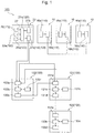
- FIG. 1 is a schematic block diagram illustrating an embodiment of the construction management system of the present disclosure.
- a construction management system 100 of the present embodiment is a system that constitutes an Internet of Things (IoT) construction solution utilizing a mobile terminal, such as a smartphone, at a construction site, for example.
- the construction management system 100 of the present embodiment realizes a site where machinery and humans are connected by IoT technology, and contributes to improvements in productivity and safety.
- IoT Internet of Things
- the construction management system 100 is provided with a position detection module 110, a weight detection device 120, and an information management controller 130.
- the position detection module 110 includes a position sensor 16a as a transport vehicle position detection device for detecting position information about a transport vehicle 10 that transports a payload, and a position sensor 26 as a loading machine position detection device for detecting position information about a loading machine 20 that loads a payload onto the transport vehicle 10.
- the weight detection device 120 detects weight information about a payload held by the loading machine 20.
- the information management controller 130 calculates the load weight of the payload loaded onto the transport vehicle 10, based on chronological information of the position information about the transport vehicle 10, chronological information of the position information about the loading machine 20, and chronological information of the weight information.
- the configuration of the elements of the construction management system 100 of the present embodiment will be described in detail.
- Fig. 1 as an example, three transport vehicles 10 and one loading machine 20 are illustrated.
- the number of the transport vehicles 10 and loading the number of the machines 20 are not particularly limited. That is, the construction management system 100 may implement construction management for one or a plurality of transport vehicles 10 and one or a plurality of loading machines 20.
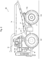
- Fig. 2 is a side view illustrating an example of the transport vehicles 10 of Fig. 1 .
- the transport vehicle 10 is a dump truck, for example.
- the transport vehicle 10 has a vehicle body frame 11, left and right front wheels 12F, left and right rear wheels 12R, left and right front wheel-side suspension devices 13F, left and right rear wheel-side suspension devices 13R, a bed 14, left and right hoist cylinders 15, a cab 16, a travel drive device 17, and a housing 18, for example.
- the payload which is loaded onto the bed 14 of the transport vehicle 10 by the loading machine 20 is not particularly limited. Examples are earth, crushed rock, and mineral resources.
- each transport vehicle 10 may be provided with a position sensor 16a for detecting the position of each transport vehicle 10 using the Global Navigation Satellite System (GNSS), for example, and a communication device 16b for transmitting the position information output from the position sensor 16a to the information management controller 130.
- GNSS Global Navigation Satellite System
- the position sensor 16a and the communication device 16b need not be necessarily installed on the transport vehicle 10, and may instead be mounted on a mobile terminal, such as a smartphone, carried by an operator riding in the cab 16 of the transport vehicle 10.
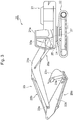
- Fig. 3 is a side view illustrating an example of the loading machine 20 of Fig. 1 .
- the loading machine 20 is a hydraulic excavator, for example.
- the loading machine 20 is provided with, for example, an upper slewing structure 21, a lower travel structure 22, a work assembly 23, attitude sensors 23s for determining the attitude of the work assembly 23, a slewing mechanism 24, hydraulic cylinders 25a, 25b, 25c, a position sensor 26, a control unit 27, and a hydraulic device which is not shown.
- the loading machine 20 is not limited to a hydraulic excavator and may include other work machines, such as a wheel loader and a crane.
- the work assembly 23 is provided in front of the upper slewing structure 21, for example, and is driven by the hydraulic cylinders 25a, 25b, 25c to perform work, such as an excavation work or a loading work.
- the work assembly 23 includes a boom 23a, an arm 23b, and a bucket 23c, for example.
- the boom 23a is pivotally supported on the upper slewing structure 21 via a boom pin.
- the arm 23b is supported movably with respect to the boom 23a via an arm pin.
- the bucket 23c is supported pivotally with respect to the arm 23b via a bucket pin.
- the attitude sensors 23s are angle sensors provided for each of the boom pin, the arm pin, and the bucket pin, for example.
- the attitude sensors 23s for example, detect a rotational angle of the boom 23a relative to the upper slewing structure 21, a rotational angle of the arm 23b relative to the boom 23a, and a rotational angle of the bucket 23c relative to the arm 23b.
- the attitude sensors 23s are not limited to angle sensors.
- other sensors capable of detecting the attitude of the work assembly 23, such as an acceleration sensor and a gyro sensor, may be used as the attitude sensors 23s.
- the hydraulic cylinders 25a, 25b, 25c are each provided with a hydraulic sensor 25s (see Fig. 1 ) for measuring an oil pressure in the cylinder tube.
- the hydraulic sensor 25s may be provided at least for the hydraulic cylinder 25a driving the boom 23a relative to the upper slewing structure 21, and may not be provided for the other hydraulic cylinders 25b, 25c.
- the hydraulic sensor 25s for example, measures the oil pressure in the cylinder tubes of the hydraulic cylinders 25a, 25b, 25c, and outputs hydraulic information corresponding to the measured oil pressure to the control unit 27.
- the position sensor 26 is configured using GNSS or the like, and detects the position of each loading machine 20.
- the control unit 27 is composed of, for example, a microcontroller or firmware installed on the loading machine 20, and is provided with a processing device 27a such as a CPU, a storage device 27b such as a RAM and a hard disk, and a communication device 27c for transmitting information to the outside.
- the position sensor 26 and the control unit 27 need not be necessarily installed on the loading machine 20, and may be mounted on, for example, a mobile terminal, such as a smartphone, carried by an operator riding in a cab 21a of the loading machine 20.
- the processing device 27a receives an input of position information about the loading machine 20 output from the position sensor 26, via a wireless communication line or a wired communication line.
- the processing device 27a also receives an input of information about the attitude of the work assembly 23 output from the attitude sensors 23s and hydraulic information output from the hydraulic sensor 25s, via a wireless communication line or a wired communication line.
- the processing device 27a processes the input information and causes the information to be stored in the storage device 27b on a predetermined periodic basis.
- the storage device 27b stores chronological information of the information input from the processing device 27a, a computer program, data, and other information, for example.
- the communication device 27c for example, transmits the information input from the processing device 27a to the information management controller 130 via a wireless communication line.
- the processing device 27a may be configured to calculate the weight of a payload held by the work assembly 23, based on the attitude of the work assembly 23 measured by the attitude sensors 23s and the oil pressure measured by the hydraulic sensor 25s, for example. More specifically, for example, in order to load payload onto the bed 14 of the transport vehicle 10 using the loading machine 20, the work assembly 23 is driven by the hydraulic cylinders 25a, 25b, 25c and payload on the ground is scooped up by the bucket 23c of the work assembly 23.
- the processing device 27a executes the computer program stored in the storage device 27b and, based on the information about the attitude of the work assembly 23 input from the attitude sensors 23s and the hydraulic information input from the hydraulic sensor 25s, calculates the weight of the payload collected in the bucket 23c of the work assembly 23. Calculation of the weight of the payload may be performed by the information management controller 130 as will be described later.
- the position detection module 110 detects position information about each transport vehicle 10 that transports payload, and position information about the loading machine 20 that loads payload onto the transport vehicle 10.
- the position detection module 110 includes the position sensor 16a (transport vehicle position detection device) and the communication device 16b mounted on the transport vehicle 10, and the position sensor 26 (loading machine position detection device) and the communication device 27c mounted on the loading machine 20, for example.
- the position sensor 16a mounted on the transport vehicle 10 detects the position of the transport vehicle 10 on a predetermined periodic basis, and outputs position information about the transport vehicle 10 including the detected position and the time of detection of the position to the communication device 16b.
- the communication device 16b transmits the position information input from the position sensor 16a to the information management controller 130 via a wireless communication line, for example.
- the position sensor 26 mounted on the loading machine 20 detects the position of the loading machine 20 on a predetermined periodic basis, and outputs position information about the loading machine 20 including the detected position and the time of detection of the position to the control unit 27.
- the communication device 27c of the control unit 27 transmits the position information about the loading machine 20 that has been input from the position sensor 26 via the processing device 27a, to the information management controller 130 via a wireless communication line, for example.
- the weight detection device 120 detects weight information about the payload held by the loading machine 20.
- the weight detection device 120 for example, includes the hydraulic sensor 25s, the attitude sensors 23s, the processing device 27a, and the communication device 27c of the loading machine 20.
- the hydraulic sensor 25s of the loading machine 20 detects the oil pressure in the cylinder tube of the hydraulic cylinder 25a on a predetermined periodic basis, and outputs hydraulic information including the oil pressure and the time of detection of the oil pressure to the processing device 27a.
- the attitude sensors 23s of the loading machine 20 for example, sense the attitude of the work assembly 23, including the angle of the boom 23a relative to the upper slewing structure 21, the angle of the arm 23b relative to the boom 23a, and the angle of the bucket 23c relative to the arm 23b on a predetermined periodic basis. The attitude sensors 23s then outputs attitude information including the attitude and the time of sensing of the attitude to the processing device 27a.
- the processing device 27a calculates the weight of the payload held by the work assembly 23, based on the hydraulic information and the attitude information input from the hydraulic sensor 25s and the attitude sensors 23s. More specifically, the storage device 27b, for example, stores dimension information about various parts of the work assembly 23 and a computer program for computing the weight of the payload held by the work assembly 23 based on the dimensions and attitudes of the various parts of the work assembly 23 and the oil pressure of the hydraulic cylinder 25a.
- the processing device 27a executes the program stored in the storage device 27b and, based on the dimension information, attitude information, and hydraulic information described above, calculates the weight of the payload collected in the bucket 23c and held by the work assembly 23.
- the processing device 27a further outputs weight information including the calculated weight and the time of detection of the weight to the communication device 27c.
- the communication device 27c transmits the weight information input from the processing device 27a to the information management controller 130 via a wireless communication line, for example.
- the information management controller 130 calculates the load weight of the payload of each transport vehicle 10, based on chronological information of the position information about the transport vehicle 10, chronological information of the position information about the loading machine 20, and chronological information of the weight information about the payload held by the work assembly 23 of the loading machine 20.
- the information management controller 130 for example, includes a position information server 131, a weight information server 132, and a user server 133.
- the weight information server 132 receives the weight information transmitted from the communication device 27c of each loading machine 20.
- the weight information server 132 for example, is provided with a receiving device 132a, a processing device 132b, a storage device 132c, and a transmitting device 132d.
- the receiving device 132a receives the weight information transmitted from the communication device 27c of the loading machine 20, and outputs the weight information to the processing device 132b.
- the processing device 132b causes the weight information input from the receiving device 132a to be stored in the storage device 132c as chronological information. Further, the processing device 132b, for example, reads the chronological information of the weight information stored in the storage device 132c, and outputs the chronological information to the transmitting device 132d.
- the transmitting device 132d transmits the chronological information of the weight data input from the processing device 132b to the position information server 131 via a wireless communication line or a wired communication line, for example.
- the control unit 27 mounted on each loading machine 20 may not calculate the weight of the payload held by the work assembly 23 of the loading machine 20.
- the processing device 27a of the control unit 27 mounted on each loading machine 20 outputs the attitude information and hydraulic information that are based on the attitude and oil pressure comprising the inputs from the attitude sensors 23s and the hydraulic sensor 25s, to the communication device 27c.
- the communication device 27c outputs the attitude information and hydraulic information input from the processing device 27a to the weight information server 132 of the information management controller 130.
- the weight information server 132 may be configured to detect the weight information about the payload held by the work assembly 23 of each loading machine 20, based on the attitude information and hydraulic information received from the communication device 27c of each loading machine 20. Specifically, for example, the receiving device 132a of the weight information server 132 receives the attitude information and weight information transmitted from the communication device 27c of the loading machine 20, and outputs the attitude information and weight information to the processing device 132b.
- the processing device 132b calculates the weight of the payload held by the work assembly 23 of each loading machine 20. Further, the processing device 132b causes weight information including the calculated weight and the time of detection of the weight to be stored in the storage device 132c as chronological information. Also, the processing device 132b reads the chronological information of the weight information stored in the storage device 132c, and outputs the chronological information to the transmitting device 132d. The transmitting device 132d transmits the chronological information of the weight information input from the processing device 132b to the position information server 131.
- the position information server 131 receives from the position detection module 110 position information about the transport vehicles 10 and position information about the loading machine 20. More specifically, the position information server 131 includes a receiving device 131a, a processing device 131b, a storage device 131c, and a transmitting device 131d, for example.
- the receiving device 131a receives the position information about each transport vehicle 10 transmitted from the communication device 16b of each transport vehicle 10, and also receives the position information about each loading machine 20 transmitted from the communication device 27c of each loading machine 20. Further, the receiving device 131a receives from the weight information server 132 the weight data of the payload held by the work assembly 23 of each loading machine 20, for example. Further, the receiving device 131a outputs the received information to the processing device 131b.
- the processing device 131b processes the information input from the processing device 131b and causes the resultant information to be stored in the storage device 131c as chronological information.
- the storage device 131c stores, for example, threshold values of distances between the loading machine 20 and the transport vehicles 10 at which the loading machine 20 can load payload onto the bed 14 of the transport vehicles 10 using the work assembly 23. Further, the processing device 131b, for example, calculates the weight of the payload loaded onto each transport vehicle 10, i.e., the load weight of the transport vehicle 10, based on the chronological information of the position information about each transport vehicle 10, the chronological information of the position information about each loading machine 20, and the chronological information of the weight information about the payload held by each loading machine 20 stored in the storage device 131c.
- the processing device 131b causes the calculated weight of the payload of each transport vehicle 10 to be stored in the storage device 132c as load weight information. Further, the processing device 131b reads the position information and load weight information about each transport vehicle 10 stored in the storage device 131c, and outputs the information to the transmitting device 131d. The transmitting device 131d transmits the information input from the processing device 131b to the user server 133, for example.
- the user server 133 creates an operation daily report based on the information received from the position information server 131, for example.
- the user server 133 is provided with a receiving device 133a, a processing device 133b, a storage device 133c, and an output device 133d, for example.
- the receiving device 133a receives the information transmitted from the transmitting device 131d of the position information server 131 and outputs the information to the processing device 133b.
- the processing device 133b causes the information input from the receiving device 133a to be stored in the storage device 133c.
- the processing device 133b may, based on the chronological information of the position information about the transport vehicle 10, the chronological information of the position information about the loading machine 20, and the chronological information of the weight information stored in the storage device 133c, calculate the load weight of the payload loaded onto each transport vehicle 10 and cause the load weight to be stored in the storage device 133c. Further, the processing device 133b, based on the information stored in the storage device 133c, calculates operation daily report data and outputs the data to the output device 133d.
- the storage device 133c stores position information about a collection site where the payload transported by the transport vehicle 10 is unloaded or dumped.
- the processing device 133b calculates, as operation daily report data, an integrated value of the weight of the payload that each transport vehicle 10 unloaded in the collection site. Further, the processing device 133b, for example, based on the position information about the collection site, the chronological information of the position information about each transport vehicle 10, and the load weight information, calculates, as operation daily report data, the travelling time of the transport vehicle 10 from a loading position where the payload was loaded onto each transport vehicle 10 to the collection site.
- the processing device 133b calculates, as operation daily report data, the number of times of movement of each transport vehicle 10 from the loading position where the payload was loaded onto the transport vehicle 10 to the collection site. Further, the processing device 133b, for example, based on the position information about each collection site and the chronological information of the position information about each transport vehicle 10 as well as the load weight information thereof, calculates, as operation daily report data, an operating time at each collection site, the number of times of movement of the transport vehicle 10 from the loading position where the payload was loaded onto each transport vehicle 10 to each collection site, and a total weight of the payload unloaded at each collection site.
- the processing device 133b causes the calculated operation daily report data to be stored in the storage device 133c, and also outputs the data to the output device 133d.
- the output device 133d includes a display device and software or a printer, for example.
- the display device outputs, in the form of an image, an operation daily report based on the operation daily report data input from the processing device 133b.
- the operation daily report may be output in the form of an electronic file by the software, or may be printed on paper and output by the printer.
- Fig. 4 shows a time chart illustrating an example of the operation of the construction management system 100 of Fig. 1 .
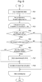
- Fig. 5 shows a flowchart illustrating the flow of a process of the weight detection device 120 included in the construction management system 100 of Fig. 1 .
- the temporal changes in the distance between one loading machine 20 and the three transport vehicles 10 are indicated by the interval between straight lines. For instance, at time t1, the distance between the loading machine 20 and the transport vehicle 10 closest to the loading machine 20 is D1. Further, at time t1, the distance between the transport vehicle 10 closest to the loading machine 20 and the transport vehicle 10 second closest to the loading machine 20 is D2. Further, the distance between the transport vehicle 10 second closest to the loading machine 20 and the transport vehicle 10 third closest to the loading machine 20 is D3.
- Fig. 4 shows a threshold value DS of a distance between the loading machine 20 and the transport vehicles 10 at which the loading machine 20, using the work assembly 23, can load the payload onto the bed 14 of the transport vehicles 10.
- Fig. 4 shows the timing of operation of the position information server 131 and the weight information server 132 of the information management controller 130.
- the construction management system 100 does not start the process illustrated in Fig. 5 until the distance between at least one loading machine 20 and at least one transport vehicle 10 becomes less than or equal to the threshold value DS.
- the construction management system 100 starts the process illustrated in Fig. 5 .
- the construction management system 100 initially performs a process P11 for acquiring sensor information.
- the construction management system 100 detects and acquires, using the position detection module 110 described above, the position information about each transport vehicle 10 and the position information about each loading machine 20. Further, the construction management system 100, using the weight detection device 120 described above, detects and acquires the weight information about the payload held by each loading machine 20.
- the position detection module 110 detects, using the position sensor 16a, which is the transport vehicle position detection device, the position information about each transport vehicle 10, and also detects, using the position sensor 26, which is the loading machine position detection device, the position information about the loading machine 20.
- the position information about the transport vehicle 10 and the position information about the loading machine 20 detected by the position sensor 16a and the position sensor 26 are transmitted by the communication device 27c to the information management controller 130.
- the weight detection device 120 measures, using the hydraulic sensor 25s of the loading machine 20, the oil pressure of the hydraulic cylinder 25a that drives the work assembly 23, and also detects, using the attitude sensors 23s of the loading machine 20, the attitude of the work assembly 23.
- the information management controller 130 calculates the weight of the payload held by the work assembly 23.
- the information about oil pressure and attitude detected by the hydraulic sensor 25s and attitude sensors 23s i.e., the hydraulic information and the attitude information are transmitted by the communication device 27c to the information management controller 130.
- the construction management system 100 performs a process P12 for calculating the weight of the payload held by the work assembly 23 of the loading machine 20.
- the weight detection device 120 calculates the weight of the payload held by the work assembly 23, based on the information about the oil pressure and attitude detected by the hydraulic sensor 25s and the attitude sensors 23s, i.e., the hydraulic information and the attitude information.
- the construction management system 100 performs a process P13 for transmitting information about the calculated weight, i.e., the weight information.
- the weight information server 132 of the information management controller 130 performs a process P14 for receiving the weight information, using the receiving device 132a.
- the weight information server 132 performs a process P15 for recording the weight information in the storage device 132c, using the processing device 132b.
- the process P12 for calculating the weight of the payload held by the work assembly 23 may be performed by, for example, the processing device 132b of the weight information server 132.
- the processing device 132b of the weight information server 132 based on the hydraulic information and attitude information transmitted from the communication device 27c of the loading machine 20 and received by the receiving device 132a, calculates the weight of the payload held by the work assembly 23.
- the process P13 for transmitting the weight information and the process P14 for receiving the weight information are omitted, and the process P15 for recording the weight information calculated by the processing device 132b in the process P12 in the storage device 132c is performed.
- the weight information server 132 performs the process P16 for determining whether the distance between the loading machine 20 and the transport vehicle 10 closest to the loading machine 20 is greater than the threshold value DS.
- the weight information server 132 for example, based on the position information about the transport vehicle 10 and the position information about the loading machine 20 received via the receiving device 132a, calculates, using the processing device 132b, the distance between the loading machine 20 and the transport vehicle 10 closest to the loading machine 20.
- the processing device 132b compares the calculated distance and the threshold value DS, and if the calculated distance is greater than the threshold value DS (YES), the construction management system 100 ends the process illustrated in Fig. 5 . On the other hand, if the calculated distance is less than or equal to the threshold value DS (NO), the construction management system 100 repeatedly performs the process P11 to the process P16 on a predetermined periodic basis, and records the weight information about the payload held by the loading machine 20 in the storage device 132c of the weight information server 132 on a predetermined periodic basis.
- the loading machine 20 before time t3, for example, is in a state in which the payload has been scooped up by the bucket 23c of the work assembly 23 and is being held by the work assembly 23. After time t3, the loading machine 20 moves toward the transport vehicle 10 so that the distance between the loading machine 20 and the transport vehicle 10 is the shortest. Then, between time t3 and time t4, the loading machine 20, for example, dumps the payload in the bucket 23c of the work assembly 23 onto the bed 14 of the nearest transport vehicle 10, thus loading the payload onto the transport vehicle 10.
- the loading machine 20 repeatedly performs, a plurality of times, the work of moving a little away from the transport vehicle 10, scooping up the payload using the bucket 23c of the work assembly 23, again approaching the transport vehicle 10, and loading the payload in the work assembly 23 onto the bed 14 of the transport vehicle 10.
- the construction management system 100 repeatedly performs the process P11 to the process P16 described above, wherein the weight information about the payload held by the work assembly 23 is transmitted from the loading machine 20 to the weight information server 132, and the chronological information of the weight information is stored in the storage device 132c.
- the transport vehicle 10 with the payload loaded thereon moves away from the loading machine 20 so that the distance between the loading machine 20 and the transport vehicle 10 is greater than the threshold value DS.
- the construction management system 100 performs a process illustrated in Fig. 6 .
- Fig. 6 is a flow diagram illustrating the flow of a process of the position information server 131 of the information management controller 130 included in the construction management system 100 of Fig. 1 .
- the position information server 131 receives the weight information transmitted from the transmitting device 132d of the weight information server 132, using the receiving device 131a.
- the construction management system 100 performs, using the processing device 131b of the position information server 131, for example, a process P22 for recording information for each loading machine 20.
- the processing device 131b of the position information server 131 causes the weight information input from the receiving device 131a to be stored in the storage device 131c as chronological information of the weight information about each loading machine 20, together with identifying information (ID), such as a user name, of the loading machine 20 and the time of measurement of weight.
- ID identifying information
- the construction management system 100 performs a data processing loop P23 for weight information.
- the processing device 131b initially determines whether, as an ending condition, the processing of the weight information about all the loading machines 20 stored in the storage device 131c is completed. If the processing of the weight information about all the loading machines 20 stored in the storage device 131c is completed, the processing device 131b ends the process illustrated in Fig. 6 . If the processing is not completed with respect to any of the weight information stored in the storage device 131c, the processing device 131b performs a process P24 for searching for the position information about the loading machine 20 stored in the storage device 131c.
- the processing device 131b searches for the position information about the loading machine 20 stored in the storage device 131c. If, as a result of the search in the process P24, there is no position information about the loading machine 20 within a predetermined range of time (NO), the processing device 131b again performs the data processing loop P23 for the weight information. On the other hand, if, as a result of the search in the process P24, there is position information about a loading machine 20 within the predetermined time, a process P25 for determining loading onto the transport vehicles 10 by the loading machine 20 is performed.
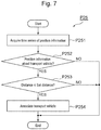
- Fig. 7 is a flow diagram illustrating the details of the loading determination process P25 of Fig. 6 .
- the processing device 131b reads from the storage device 131c the chronological information of the position information about the loading machine 20 and the chronological information of the position information about the transport vehicles 10. Then, in a process P252, the processing device 131b searches for the position information about the transport vehicles 10 in a predetermined range of time. In the process P252, if there is no position information about the transport vehicles 10 (NO), the processing device 131b ends the process P25 and returns to the end determination of the data processing loop P23 of Fig. 6 . On the other hand, if there is the position information about the transport vehicles 10 in the process P252 (YES), the processing device 131b performs a process P253.
- the processing device 131b calculates the distance between the loading machine 20 and the transport vehicles 10 at each time. Further, the processing device 131b determines whether the calculated distance is less than or equal to a set distance, such as the distance threshold value DS. If, as a result of the determination, the calculated distance is greater than the set distance (NO), the processing device 131b ends the process P25 and returns to the end determination of the data processing loop P23 of Fig. 6 . On the other hand, if, as a result of the determination, the calculated distance is less than or equal to the set distance (YES), the processing device 131b performs a process P254.
- a set distance such as the distance threshold value DS
- the processing device 131b associates, as the transport vehicle 10 for loading, the transport vehicle 10 of which the distance from the loading machine 20 is less than or equal to the set distance, i.e., the threshold value DS, with the position information about the loading machine 20.
- the processing device 131b then ends the process P25 and performs a process P26 of Fig. 6 .
- the processing device 131b determines whether, as a result of the process P25, a plurality of transport vehicles 10 are associated as the transport vehicle 10 for loading by the loading machine 20. If, as a result of the determination, a plurality of transport vehicles 10 are associated as the object for loading by one loading machine 20 (YES), the processing device 131b performs a process P27 for recording in the storage device 131c the transport vehicle 10 closest to the loading machine 20 as the object for loading and the other transport vehicles 10 as not the object for loading. After the end of the process P27, the processing device 131b performs a process P28. On the other hand, if, as a result of the determination in the process P26, one transport vehicle 10 is associated as the object for loading by the one loading machine 20 (NO), the processing device 131b performs the process P28.
- the processing device 131b based on a positive determination result (YES) in the process P26, proceeds to the process P27, associates one closest transport vehicle 10 as the object for loading by the loading machine 20, and proceeds to the process P28.
- the processing device 131b records in the storage device 131c the transport vehicle 10 that has been associated as the object for loading by the loading machine 20, in association with the weight information about the loading machine 20. Thereafter, the processing device 131b repeatedly performs the data processing loop P23 until data processing of all weight information stored in the storage device 131c ends. When the data processing of all the weight information stored in the storage device 131c ends, the processing device 131b ends the process of Fig. 6 .
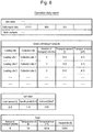
- Fig. 8 illustrates an example of the operation daily report output by the user server 133 illustrated in Fig. 1 .
- the weight information about the loading machine 20 associated with the transport vehicle 10 for loading in the position information server 131 is transmitted to the user server 133 via the transmitting device 131d, and received by the receiving device 133a of the user server 133.
- the receiving device 133a outputs the received information to the processing device 131b.
- the processing device 131b calculates operation daily report data based on the information input from the receiving device 133a and the information stored in the storage device 133c, and outputs the calculated data to the output device 133d.
- the output device 133d outputs the operation daily report as illustrated in Fig. 8 , based on the operation daily report data input from the processing device 133b.
- the construction management system 100 of the present embodiment is provided with the position sensor 16a as a transport vehicle position detection device, the position sensor 26 as a loading machine position detection device, the weight detection device 120, and the information management controller 130.
- the position sensor 16a detects the position information about the transport vehicle 10 that transports a payload.
- the position sensor 26 detects the position information about the loading machine 20 that loads the payload onto the transport vehicle 10.
- the weight detection device 120 detects the weight information about the payload held by the loading machine 20.
- the information management controller 130 based on the chronological information of the position information about the transport vehicle 10, the chronological information of the position information about the loading machine 20, and the chronological information of the weight information, calculates the load weight of the payload loaded onto the transport vehicle 10.
- the weight information about the payload held by the loading machine 20 is detected when the payload is loaded onto the transport vehicle 10. Further, in the construction management system 100 of the present embodiment, the load weight of the payload loaded onto the transport vehicle 10 is calculated based on the chronological information of the position information about the transport vehicle 10, the chronological information of the position information about the loading machine 20, and the chronological information of the weight information. Thus, even if no loading work has been performed although the transport vehicle 10 and the loading machine 20 approached each other, that fact can be accurately ascertained, so that the total amount of load transported from the construction site by the transport vehicle 10 can be more accurately ascertained.
- the information management controller 130 based on the position information about the collection site where the payload transported by each transport vehicle 10 is unloaded or dumped, the chronological information of the position information about the transport vehicle 10, and the load weight, the integrated value of the weight of the payload unloaded by the transport vehicle 10 onto the collection site is calculated.
- This configuration facilitates the creation of the operation daily report including the integrated value of the weight of the payload unloaded by the transport vehicle 10 onto the collection site, thus reducing a burden on the user.
- the information management controller 130 based on the position information about the collection site where the payload transported by the transport vehicle 10 is unloaded or dumped, the chronological information of the position information about the transport vehicle 10, and the load weight, the travelling time of the transport vehicle 10 from the loading position where the payload is loaded onto the transport vehicle 10 to the collection site is calculated.
- This configuration facilitates the creation of the operation daily report including the travelling time of the transport vehicle 10 from the loading position where the payload is loaded onto the transport vehicle 10 to the collection site, thus reducing a burden on the user.
- the information management controller 130 based on the position information about the collection site where the payload transported by each transport vehicle 10 is unloaded or dumped, the chronological information of the position information about the transport vehicle 10, and the load weight, the number of times of movement of the transport vehicle 10 from the loading position where the payload is loaded onto the transport vehicle 10 to the collection site is calculated.
- This configuration facilitates the creation of the operation daily report including the number of times of movement of the transport vehicle 10 from the loading position where the payload is loaded onto the transport vehicle 10 to the collection site, thus reducing a burden on the user.
- the information management controller 130 calculates the operating time at each collection site, the number of times of movement of the transport vehicle from the loading position where the payload is loaded onto the transport vehicle to each collection site, and the total weight of the payload unloaded at each collection site.
- This configuration facilitates the creation of the operation daily report including the operating time at each collection site, the number of times of movement of the transport vehicle from the loading position where the payload is loaded onto the transport vehicle to each collection site, and the total weight of the payload unloaded at each collection site, thus reducing a burden on the user.
- the position detection module 110 includes the position sensor 16a as a transport vehicle position detection device, the position sensor 26 as a loading machine position detection device, and the communication device 16b and the communication device 27c.
- the position sensor 16a detects the position information about each transport vehicle 10.
- the position sensor 26 detects the position information about the loading machine 20.
- the communication device 16b transmits the position information about the transport vehicle 10 detected by the position sensor 16a to the information management controller 130.
- the communication device 27c transmits the position information about the loading machine 20 detected by the position sensor 26 to the information management controller 130. This configuration allows the information management controller 130 to acquire the chronological information of the position information about each transport vehicle 10 and the chronological information of the position information about each loading machine 20.
- the weight detection device 120 includes the hydraulic sensor 25s, the attitude sensors 23s, the processing device 27a, and the communication device 27c.
- the hydraulic sensor 25s measures the oil pressure of the hydraulic cylinder 25a for driving the work assembly 23 of the loading machine 20.
- the attitude sensors 23s detect the attitude of the work assembly 23.
- the processing device 27a based on the oil pressure and attitude detected by the hydraulic sensor 25s and the attitude sensors 23s, calculates the weight of the payload held by the work assembly 23.
- the communication device 27c transmits weight information that is the information about the weight calculated by the processing device 27a to the information management controller 130. This configuration allows the information management controller 130 to receive the weight information from each loading machine 20 and to acquire the chronological information of the weight information about each loading machine 20.
- the information management controller 130 includes the position information server 131, the weight information server 132, the storage device 131c, and the processing device 133b.
- the position information server 131 receives the position information about each transport vehicle 10 and the position information about the transport vehicles 10 from the position detection module 110.
- the weight information server 132 receives the weight information from the weight detection device 120.
- the storage device 131c stores the position information about the transport vehicles 10, the position information about the loading machine 20, and the weight information.
- the processing device 133b calculates the load weight of the transport vehicle 10. This configuration allows the construction management system 100 to ascertain information about the construction site more accurately than before.
- the construction management system 100 capable of ascertaining information about a construction site more accurately than before.
Landscapes
- Engineering & Computer Science (AREA)
- Business, Economics & Management (AREA)
- Human Resources & Organizations (AREA)
- Economics (AREA)
- Strategic Management (AREA)
- Physics & Mathematics (AREA)
- General Physics & Mathematics (AREA)
- General Business, Economics & Management (AREA)
- Tourism & Hospitality (AREA)
- Marketing (AREA)
- Theoretical Computer Science (AREA)
- Entrepreneurship & Innovation (AREA)
- Computing Systems (AREA)
- Development Economics (AREA)
- Health & Medical Sciences (AREA)
- General Health & Medical Sciences (AREA)
- Operations Research (AREA)
- Quality & Reliability (AREA)
- Primary Health Care (AREA)
- Radar, Positioning & Navigation (AREA)
- Remote Sensing (AREA)
- Game Theory and Decision Science (AREA)
- Educational Administration (AREA)
- Toxicology (AREA)
- Environmental & Geological Engineering (AREA)
- Accounting & Taxation (AREA)
- Computer Networks & Wireless Communication (AREA)
- Mining & Mineral Resources (AREA)
- Civil Engineering (AREA)
- General Engineering & Computer Science (AREA)
- Structural Engineering (AREA)
- Signal Processing (AREA)
- Data Mining & Analysis (AREA)
- Management, Administration, Business Operations System, And Electronic Commerce (AREA)
- Operation Control Of Excavators (AREA)
Abstract
Description
- The present disclosure relates to a construction management system.
- Conventionally, a construction management system is known which is provided with an emitter, a portable terminal, a receiving unit, a detecting unit, a specific data acquiring unit, and a work managing unit (see
claim 1 ofPatent Literature 1 indicated below, for example). The emitter is disposed on a transport vehicle and emits radio waves including specific data of the transport vehicle. The portable terminal is disposed on a loading machine. The receiving unit is provided in the portable terminal and receives the radio waves from the emitter. - The detecting unit is provided in the portable terminal and detects the intensity of the radio waves received by the receiving unit. The specific data acquiring unit is provided in the portable terminal and acquires the specific data from the radio waves received by the receiving unit. The work managing unit generates actual performance data indicating that the transport vehicle has approached the loading machine, based on the intensity detected by the detecting unit and the specific data acquired by the specific data acquiring unit.
- Further, the work managing unit determines that the loading machine is performing a loading work for loading a load onto the transport vehicle if the intensity of the radio waves received by the receiving unit is a value greater than or equal to a threshold value (see
claim 3 of the literature, for example). Further, the work managing unit determines that the transport vehicle has started a transport work for transporting the load if the intensity of the radio waves received by the receiving unit has changed from a value greater than or equal to the threshold value to a value lower than the threshold value (see claim 4 of the literature, for example). - Patent Literature 1:
WO 2015/156018 - The conventional construction system, by utilizing a change in the intensity of the radio waves received by the receiving unit in accordance with the distance from the emitter, makes a determination for implementing the loading work and a determination for starting the transport work based on a threshold value of the intensity of the radio waves (see claims 3-4 and paragraph 0022, for example, of the patent literature). Further, the total amount of load transported from the construction site is calculated based on the maximum payload capacity data of the transport vehicle and at least one of data on the number of times of approach and data on the number of withdrawals (see paragraph 0084 of the patent literature, for example). However, even when the loading machine and the transport vehicle have approached each other and the intensity of the radio waves has become greater than or equal to the threshold value, no loading work may be actually implemented. This leads to the problem that the total amount of load transported from the construction site cannot be accurately ascertained.
- The present disclosure provides a construction management system with which it is possible to ascertain information about a construction site more accurately than before.
- According to an embodiment of the present disclosure, a construction management system includes a transport vehicle position detection device which detects position information about a transport vehicle for transporting a payload, a loading machine position detection device which detects position information about a loading machine for loading the payload onto the transport vehicle, a weight detection device which detects weight information about the payload held by the loading machine, and an information management controller which, based on chronological information of the position information about the transport vehicle, chronological information of the position information about the loading machine, and chronological information of the weight information, calculates a load weight of the payload loaded onto the transport vehicle.
- According to the present disclosure, it is possible to provide a construction management system capable of ascertaining information about a construction site more accurately than before.
-
-
Fig. 1 is a schematic block diagram illustrating an embodiment of a construction management system of the present disclosure. -
Fig. 2 is a side view illustrating an example of a transport vehicle ofFig. 1 . -
Fig. 3 is a side view illustrating an example of a loading machine ofFig. 1 . -
Fig. 4 is a time chart illustrating the operation of a position information server and a weight information server ofFig. 1 . -
Fig. 5 is a flowchart showing the flow of processing of the weight information server ofFig. 1 . -
Fig. 6 is a flowchart showing the flow of processing of the position information server ofFig. 1 . -
Fig. 7 is a flowchart showing the details of processing for determining the approach of a transport vehicle ofFig. 6 . -
Fig. 8 illustrates an example of an operation daily report output by a user server ofFig. 1 . - In the following, an embodiment of a construction management system of the present disclosure will be described with reference to the drawings.
-
Fig. 1 is a schematic block diagram illustrating an embodiment of the construction management system of the present disclosure. Aconstruction management system 100 of the present embodiment is a system that constitutes an Internet of Things (IoT) construction solution utilizing a mobile terminal, such as a smartphone, at a construction site, for example. Theconstruction management system 100 of the present embodiment realizes a site where machinery and humans are connected by IoT technology, and contributes to improvements in productivity and safety. - While the details will be described later, the
construction management system 100 of the present embodiment have the following major features. Theconstruction management system 100 is provided with aposition detection module 110, aweight detection device 120, and aninformation management controller 130. Theposition detection module 110 includes aposition sensor 16a as a transport vehicle position detection device for detecting position information about atransport vehicle 10 that transports a payload, and aposition sensor 26 as a loading machine position detection device for detecting position information about aloading machine 20 that loads a payload onto thetransport vehicle 10. Theweight detection device 120 detects weight information about a payload held by theloading machine 20. Theinformation management controller 130 calculates the load weight of the payload loaded onto thetransport vehicle 10, based on chronological information of the position information about thetransport vehicle 10, chronological information of the position information about theloading machine 20, and chronological information of the weight information. In the following, the configuration of the elements of theconstruction management system 100 of the present embodiment will be described in detail. - In
Fig. 1 , as an example, threetransport vehicles 10 and oneloading machine 20 are illustrated. However, the number of thetransport vehicles 10 and loading the number of themachines 20 are not particularly limited. That is, theconstruction management system 100 may implement construction management for one or a plurality oftransport vehicles 10 and one or a plurality ofloading machines 20. -
Fig. 2 is a side view illustrating an example of thetransport vehicles 10 ofFig. 1 . Thetransport vehicle 10 is a dump truck, for example. Thetransport vehicle 10 has avehicle body frame 11, left and rightfront wheels 12F, left and rightrear wheels 12R, left and right front wheel-side suspension devices 13F, left and right rear wheel-side suspension devices 13R, abed 14, left andright hoist cylinders 15, acab 16, atravel drive device 17, and ahousing 18, for example. The payload which is loaded onto thebed 14 of thetransport vehicle 10 by theloading machine 20 is not particularly limited. Examples are earth, crushed rock, and mineral resources. - As illustrated in
Fig. 1 , eachtransport vehicle 10 may be provided with aposition sensor 16a for detecting the position of eachtransport vehicle 10 using the Global Navigation Satellite System (GNSS), for example, and acommunication device 16b for transmitting the position information output from theposition sensor 16a to theinformation management controller 130. Theposition sensor 16a and thecommunication device 16b need not be necessarily installed on thetransport vehicle 10, and may instead be mounted on a mobile terminal, such as a smartphone, carried by an operator riding in thecab 16 of thetransport vehicle 10. -
Fig. 3 is a side view illustrating an example of theloading machine 20 ofFig. 1 . Theloading machine 20 is a hydraulic excavator, for example. Theloading machine 20 is provided with, for example, anupper slewing structure 21, alower travel structure 22, awork assembly 23,attitude sensors 23s for determining the attitude of thework assembly 23, aslewing mechanism 24,hydraulic cylinders position sensor 26, acontrol unit 27, and a hydraulic device which is not shown. Theloading machine 20 is not limited to a hydraulic excavator and may include other work machines, such as a wheel loader and a crane. - The
work assembly 23 is provided in front of theupper slewing structure 21, for example, and is driven by thehydraulic cylinders work assembly 23 includes aboom 23a, anarm 23b, and abucket 23c, for example. Theboom 23a is pivotally supported on theupper slewing structure 21 via a boom pin. Thearm 23b is supported movably with respect to theboom 23a via an arm pin. Thebucket 23c is supported pivotally with respect to thearm 23b via a bucket pin. - The
attitude sensors 23s are angle sensors provided for each of the boom pin, the arm pin, and the bucket pin, for example. Theattitude sensors 23s, for example, detect a rotational angle of theboom 23a relative to theupper slewing structure 21, a rotational angle of thearm 23b relative to theboom 23a, and a rotational angle of thebucket 23c relative to thearm 23b. Theattitude sensors 23s are not limited to angle sensors. For example, other sensors capable of detecting the attitude of thework assembly 23, such as an acceleration sensor and a gyro sensor, may be used as theattitude sensors 23s. - While not illustrated in
Fig. 3 , thehydraulic cylinders Fig. 1 ) for measuring an oil pressure in the cylinder tube. The hydraulic sensor 25s may be provided at least for thehydraulic cylinder 25a driving theboom 23a relative to theupper slewing structure 21, and may not be provided for the otherhydraulic cylinders hydraulic cylinders control unit 27. - The
position sensor 26 is configured using GNSS or the like, and detects the position of eachloading machine 20. Thecontrol unit 27 is composed of, for example, a microcontroller or firmware installed on theloading machine 20, and is provided with aprocessing device 27a such as a CPU, astorage device 27b such as a RAM and a hard disk, and a communication device 27c for transmitting information to the outside. Theposition sensor 26 and thecontrol unit 27 need not be necessarily installed on theloading machine 20, and may be mounted on, for example, a mobile terminal, such as a smartphone, carried by an operator riding in acab 21a of theloading machine 20. - The
processing device 27a receives an input of position information about theloading machine 20 output from theposition sensor 26, via a wireless communication line or a wired communication line. Theprocessing device 27a also receives an input of information about the attitude of thework assembly 23 output from theattitude sensors 23s and hydraulic information output from the hydraulic sensor 25s, via a wireless communication line or a wired communication line. Theprocessing device 27a processes the input information and causes the information to be stored in thestorage device 27b on a predetermined periodic basis. - The
storage device 27b stores chronological information of the information input from theprocessing device 27a, a computer program, data, and other information, for example. The communication device 27c, for example, transmits the information input from theprocessing device 27a to theinformation management controller 130 via a wireless communication line. - Further, the
processing device 27a may be configured to calculate the weight of a payload held by thework assembly 23, based on the attitude of thework assembly 23 measured by theattitude sensors 23s and the oil pressure measured by the hydraulic sensor 25s, for example. More specifically, for example, in order to load payload onto thebed 14 of thetransport vehicle 10 using theloading machine 20, thework assembly 23 is driven by thehydraulic cylinders bucket 23c of thework assembly 23. - At this time, the
processing device 27a, for example, executes the computer program stored in thestorage device 27b and, based on the information about the attitude of thework assembly 23 input from theattitude sensors 23s and the hydraulic information input from the hydraulic sensor 25s, calculates the weight of the payload collected in thebucket 23c of thework assembly 23. Calculation of the weight of the payload may be performed by theinformation management controller 130 as will be described later. - The
position detection module 110, as mentioned above, detects position information about eachtransport vehicle 10 that transports payload, and position information about theloading machine 20 that loads payload onto thetransport vehicle 10. Theposition detection module 110 includes theposition sensor 16a (transport vehicle position detection device) and thecommunication device 16b mounted on thetransport vehicle 10, and the position sensor 26 (loading machine position detection device) and the communication device 27c mounted on theloading machine 20, for example. - The
position sensor 16a mounted on thetransport vehicle 10 detects the position of thetransport vehicle 10 on a predetermined periodic basis, and outputs position information about thetransport vehicle 10 including the detected position and the time of detection of the position to thecommunication device 16b. Thecommunication device 16b transmits the position information input from theposition sensor 16a to theinformation management controller 130 via a wireless communication line, for example. - Similarly, the
position sensor 26 mounted on theloading machine 20 detects the position of theloading machine 20 on a predetermined periodic basis, and outputs position information about theloading machine 20 including the detected position and the time of detection of the position to thecontrol unit 27. The communication device 27c of thecontrol unit 27 transmits the position information about theloading machine 20 that has been input from theposition sensor 26 via theprocessing device 27a, to theinformation management controller 130 via a wireless communication line, for example. - The
weight detection device 120, as mentioned above, detects weight information about the payload held by theloading machine 20. Theweight detection device 120, for example, includes the hydraulic sensor 25s, theattitude sensors 23s, theprocessing device 27a, and the communication device 27c of theloading machine 20. - The hydraulic sensor 25s of the
loading machine 20, for example, detects the oil pressure in the cylinder tube of thehydraulic cylinder 25a on a predetermined periodic basis, and outputs hydraulic information including the oil pressure and the time of detection of the oil pressure to theprocessing device 27a. Theattitude sensors 23s of theloading machine 20, for example, sense the attitude of thework assembly 23, including the angle of theboom 23a relative to theupper slewing structure 21, the angle of thearm 23b relative to theboom 23a, and the angle of thebucket 23c relative to thearm 23b on a predetermined periodic basis. Theattitude sensors 23s then outputs attitude information including the attitude and the time of sensing of the attitude to theprocessing device 27a. - The
processing device 27a calculates the weight of the payload held by thework assembly 23, based on the hydraulic information and the attitude information input from the hydraulic sensor 25s and theattitude sensors 23s. More specifically, thestorage device 27b, for example, stores dimension information about various parts of thework assembly 23 and a computer program for computing the weight of the payload held by thework assembly 23 based on the dimensions and attitudes of the various parts of thework assembly 23 and the oil pressure of thehydraulic cylinder 25a. - The
processing device 27a executes the program stored in thestorage device 27b and, based on the dimension information, attitude information, and hydraulic information described above, calculates the weight of the payload collected in thebucket 23c and held by thework assembly 23. Theprocessing device 27a further outputs weight information including the calculated weight and the time of detection of the weight to the communication device 27c. The communication device 27c transmits the weight information input from theprocessing device 27a to theinformation management controller 130 via a wireless communication line, for example. - The
information management controller 130, as mentioned above, calculates the load weight of the payload of eachtransport vehicle 10, based on chronological information of the position information about thetransport vehicle 10, chronological information of the position information about theloading machine 20, and chronological information of the weight information about the payload held by thework assembly 23 of theloading machine 20. Theinformation management controller 130, for example, includes aposition information server 131, aweight information server 132, and auser server 133. - The
weight information server 132, for example, receives the weight information transmitted from the communication device 27c of eachloading machine 20. Theweight information server 132, for example, is provided with areceiving device 132a, aprocessing device 132b, astorage device 132c, and atransmitting device 132d. - The receiving
device 132a, for example, receives the weight information transmitted from the communication device 27c of theloading machine 20, and outputs the weight information to theprocessing device 132b. Theprocessing device 132b, for example, causes the weight information input from the receivingdevice 132a to be stored in thestorage device 132c as chronological information. Further, theprocessing device 132b, for example, reads the chronological information of the weight information stored in thestorage device 132c, and outputs the chronological information to thetransmitting device 132d. The transmittingdevice 132d transmits the chronological information of the weight data input from theprocessing device 132b to theposition information server 131 via a wireless communication line or a wired communication line, for example. - The
control unit 27 mounted on eachloading machine 20 may not calculate the weight of the payload held by thework assembly 23 of theloading machine 20. In this case, theprocessing device 27a of thecontrol unit 27 mounted on eachloading machine 20 outputs the attitude information and hydraulic information that are based on the attitude and oil pressure comprising the inputs from theattitude sensors 23s and the hydraulic sensor 25s, to the communication device 27c. The communication device 27c outputs the attitude information and hydraulic information input from theprocessing device 27a to theweight information server 132 of theinformation management controller 130. - In this case, for example, the
weight information server 132 may be configured to detect the weight information about the payload held by thework assembly 23 of eachloading machine 20, based on the attitude information and hydraulic information received from the communication device 27c of eachloading machine 20. Specifically, for example, the receivingdevice 132a of theweight information server 132 receives the attitude information and weight information transmitted from the communication device 27c of theloading machine 20, and outputs the attitude information and weight information to theprocessing device 132b. - The
processing device 132b, based on the attitude information and weight information input from the receivingdevice 132a, calculates the weight of the payload held by thework assembly 23 of eachloading machine 20. Further, theprocessing device 132b causes weight information including the calculated weight and the time of detection of the weight to be stored in thestorage device 132c as chronological information. Also, theprocessing device 132b reads the chronological information of the weight information stored in thestorage device 132c, and outputs the chronological information to thetransmitting device 132d. The transmittingdevice 132d transmits the chronological information of the weight information input from theprocessing device 132b to theposition information server 131. - The
position information server 131 receives from theposition detection module 110 position information about thetransport vehicles 10 and position information about theloading machine 20. More specifically, theposition information server 131 includes areceiving device 131a, aprocessing device 131b, astorage device 131c, and atransmitting device 131d, for example. - The receiving
device 131a receives the position information about eachtransport vehicle 10 transmitted from thecommunication device 16b of eachtransport vehicle 10, and also receives the position information about eachloading machine 20 transmitted from the communication device 27c of eachloading machine 20. Further, the receivingdevice 131a receives from theweight information server 132 the weight data of the payload held by thework assembly 23 of eachloading machine 20, for example. Further, the receivingdevice 131a outputs the received information to theprocessing device 131b. - The
processing device 131b processes the information input from theprocessing device 131b and causes the resultant information to be stored in thestorage device 131c as chronological information. Thestorage device 131c stores, for example, threshold values of distances between theloading machine 20 and thetransport vehicles 10 at which theloading machine 20 can load payload onto thebed 14 of thetransport vehicles 10 using thework assembly 23. Further, theprocessing device 131b, for example, calculates the weight of the payload loaded onto eachtransport vehicle 10, i.e., the load weight of thetransport vehicle 10, based on the chronological information of the position information about eachtransport vehicle 10, the chronological information of the position information about eachloading machine 20, and the chronological information of the weight information about the payload held by eachloading machine 20 stored in thestorage device 131c. - In addition, the
processing device 131b causes the calculated weight of the payload of eachtransport vehicle 10 to be stored in thestorage device 132c as load weight information. Further, theprocessing device 131b reads the position information and load weight information about eachtransport vehicle 10 stored in thestorage device 131c, and outputs the information to thetransmitting device 131d. The transmittingdevice 131d transmits the information input from theprocessing device 131b to theuser server 133, for example. - The
user server 133 creates an operation daily report based on the information received from theposition information server 131, for example. Theuser server 133 is provided with areceiving device 133a, aprocessing device 133b, astorage device 133c, and anoutput device 133d, for example. - The receiving
device 133a receives the information transmitted from the transmittingdevice 131d of theposition information server 131 and outputs the information to theprocessing device 133b. Theprocessing device 133b causes the information input from the receivingdevice 133a to be stored in thestorage device 133c. In an example, theprocessing device 133b may, based on the chronological information of the position information about thetransport vehicle 10, the chronological information of the position information about theloading machine 20, and the chronological information of the weight information stored in thestorage device 133c, calculate the load weight of the payload loaded onto eachtransport vehicle 10 and cause the load weight to be stored in thestorage device 133c. Further, theprocessing device 133b, based on the information stored in thestorage device 133c, calculates operation daily report data and outputs the data to theoutput device 133d. - More specifically, the
storage device 133c, for example, stores position information about a collection site where the payload transported by thetransport vehicle 10 is unloaded or dumped. Theprocessing device 133b, for example, based on the position information about the collection site and the chronological information of the position information about eachtransport vehicle 10 as well as the load weight information thereof, calculates, as operation daily report data, an integrated value of the weight of the payload that eachtransport vehicle 10 unloaded in the collection site. Further, theprocessing device 133b, for example, based on the position information about the collection site, the chronological information of the position information about eachtransport vehicle 10, and the load weight information, calculates, as operation daily report data, the travelling time of thetransport vehicle 10 from a loading position where the payload was loaded onto eachtransport vehicle 10 to the collection site. - In addition, the
processing device 133b, for example, based on the position information about the collection site and the chronological information of the position information about eachtransport vehicle 10 as well as the load weight thereof, calculates, as operation daily report data, the number of times of movement of eachtransport vehicle 10 from the loading position where the payload was loaded onto thetransport vehicle 10 to the collection site. Further, theprocessing device 133b, for example, based on the position information about each collection site and the chronological information of the position information about eachtransport vehicle 10 as well as the load weight information thereof, calculates, as operation daily report data, an operating time at each collection site, the number of times of movement of thetransport vehicle 10 from the loading position where the payload was loaded onto eachtransport vehicle 10 to each collection site, and a total weight of the payload unloaded at each collection site. - The
processing device 133b causes the calculated operation daily report data to be stored in thestorage device 133c, and also outputs the data to theoutput device 133d. Theoutput device 133d includes a display device and software or a printer, for example. The display device outputs, in the form of an image, an operation daily report based on the operation daily report data input from theprocessing device 133b. The operation daily report may be output in the form of an electronic file by the software, or may be printed on paper and output by the printer. - In the following, with reference to
Fig. 4 to Fig. 8 , operation of theconstruction management system 100 of the present embodiment is described.Fig. 4 shows a time chart illustrating an example of the operation of theconstruction management system 100 ofFig. 1 .Fig. 5 shows a flowchart illustrating the flow of a process of theweight detection device 120 included in theconstruction management system 100 ofFig. 1 . - In
Fig. 4 , the temporal changes in the distance between oneloading machine 20 and the threetransport vehicles 10 are indicated by the interval between straight lines. For instance, at time t1, the distance between theloading machine 20 and thetransport vehicle 10 closest to theloading machine 20 is D1. Further, at time t1, the distance between thetransport vehicle 10 closest to theloading machine 20 and thetransport vehicle 10 second closest to theloading machine 20 is D2. Further, the distance between thetransport vehicle 10 second closest to theloading machine 20 and thetransport vehicle 10 third closest to theloading machine 20 is D3. - Moreover,
Fig. 4 shows a threshold value DS of a distance between theloading machine 20 and thetransport vehicles 10 at which theloading machine 20, using thework assembly 23, can load the payload onto thebed 14 of thetransport vehicles 10. In addition,Fig. 4 shows the timing of operation of theposition information server 131 and theweight information server 132 of theinformation management controller 130. - In the example illustrated in
Fig. 4 , at time t1, the distances (D1, D1+D2, D1+D2+D3) between oneloading machine 20 and the threetransport vehicles 10 are greater than the threshold value DS. In this case, theconstruction management system 100, for example, does not start the process illustrated inFig. 5 until the distance between at least oneloading machine 20 and at least onetransport vehicle 10 becomes less than or equal to the threshold value DS. For example, at time t2, when the distance between oneloading machine 20 and onetransport vehicle 10 becomes less than or equal to the threshold value DS, theconstruction management system 100 starts the process illustrated inFig. 5 . - As illustrated in
Fig. 5 , theconstruction management system 100 initially performs a process P11 for acquiring sensor information. In the process P11, theconstruction management system 100 detects and acquires, using theposition detection module 110 described above, the position information about eachtransport vehicle 10 and the position information about eachloading machine 20. Further, theconstruction management system 100, using theweight detection device 120 described above, detects and acquires the weight information about the payload held by eachloading machine 20. - More specifically, in the process P11, the
position detection module 110 detects, using theposition sensor 16a, which is the transport vehicle position detection device, the position information about eachtransport vehicle 10, and also detects, using theposition sensor 26, which is the loading machine position detection device, the position information about theloading machine 20. The position information about thetransport vehicle 10 and the position information about theloading machine 20 detected by theposition sensor 16a and theposition sensor 26 are transmitted by the communication device 27c to theinformation management controller 130. - Also, in the process P11, the
weight detection device 120 measures, using the hydraulic sensor 25s of theloading machine 20, the oil pressure of thehydraulic cylinder 25a that drives thework assembly 23, and also detects, using theattitude sensors 23s of theloading machine 20, the attitude of thework assembly 23. When the weight of the payload held by thework assembly 23 is calculated by theinformation management controller 130, the information about oil pressure and attitude detected by the hydraulic sensor 25s andattitude sensors 23s, i.e., the hydraulic information and the attitude information are transmitted by the communication device 27c to theinformation management controller 130. After the end of the process P11, theconstruction management system 100 performs a process P12 for calculating the weight of the payload held by thework assembly 23 of theloading machine 20. - In the process P12, the
weight detection device 120, for example, using theprocessing device 27a of thecontrol unit 27 mounted on theloading machine 20, calculates the weight of the payload held by thework assembly 23, based on the information about the oil pressure and attitude detected by the hydraulic sensor 25s and theattitude sensors 23s, i.e., the hydraulic information and the attitude information. After the end of the process P12, theconstruction management system 100 performs a process P13 for transmitting information about the calculated weight, i.e., the weight information. - In the process P13, the communication device 27c of the
control unit 27 mounted on theloading machine 20, for example, transmits the weight information calculated by theprocessing device 27a to theinformation management controller 130. Then, theweight information server 132 of theinformation management controller 130 performs a process P14 for receiving the weight information, using thereceiving device 132a. Then, theweight information server 132 performs a process P15 for recording the weight information in thestorage device 132c, using theprocessing device 132b. - The process P12 for calculating the weight of the payload held by the
work assembly 23 may be performed by, for example, theprocessing device 132b of theweight information server 132. In this case, theprocessing device 132b of theweight information server 132, based on the hydraulic information and attitude information transmitted from the communication device 27c of theloading machine 20 and received by the receivingdevice 132a, calculates the weight of the payload held by thework assembly 23. In this case, the process P13 for transmitting the weight information and the process P14 for receiving the weight information are omitted, and the process P15 for recording the weight information calculated by theprocessing device 132b in the process P12 in thestorage device 132c is performed. - Then, the
weight information server 132, for example, performs the process P16 for determining whether the distance between theloading machine 20 and thetransport vehicle 10 closest to theloading machine 20 is greater than the threshold value DS. In the process P16, theweight information server 132, for example, based on the position information about thetransport vehicle 10 and the position information about theloading machine 20 received via thereceiving device 132a, calculates, using theprocessing device 132b, the distance between theloading machine 20 and thetransport vehicle 10 closest to theloading machine 20. - Further, in the process P16, the
processing device 132b compares the calculated distance and the threshold value DS, and if the calculated distance is greater than the threshold value DS (YES), theconstruction management system 100 ends the process illustrated inFig. 5 . On the other hand, if the calculated distance is less than or equal to the threshold value DS (NO), theconstruction management system 100 repeatedly performs the process P11 to the process P16 on a predetermined periodic basis, and records the weight information about the payload held by theloading machine 20 in thestorage device 132c of theweight information server 132 on a predetermined periodic basis. - In the example illustrated in
Fig. 4 , theloading machine 20, before time t3, for example, is in a state in which the payload has been scooped up by thebucket 23c of thework assembly 23 and is being held by thework assembly 23. After time t3, theloading machine 20 moves toward thetransport vehicle 10 so that the distance between theloading machine 20 and thetransport vehicle 10 is the shortest. Then, between time t3 and time t4, theloading machine 20, for example, dumps the payload in thebucket 23c of thework assembly 23 onto thebed 14 of thenearest transport vehicle 10, thus loading the payload onto thetransport vehicle 10. - Further, between time t4 and time t5, the
loading machine 20 repeatedly performs, a plurality of times, the work of moving a little away from thetransport vehicle 10, scooping up the payload using thebucket 23c of thework assembly 23, again approaching thetransport vehicle 10, and loading the payload in thework assembly 23 onto thebed 14 of thetransport vehicle 10. At this time, theconstruction management system 100 repeatedly performs the process P11 to the process P16 described above, wherein the weight information about the payload held by thework assembly 23 is transmitted from theloading machine 20 to theweight information server 132, and the chronological information of the weight information is stored in thestorage device 132c. - Thereafter, at time t6, the
transport vehicle 10 with the payload loaded thereon moves away from theloading machine 20 so that the distance between theloading machine 20 and thetransport vehicle 10 is greater than the threshold value DS. Thus, at time t7 after time t6, theconstruction management system 100 performs a process illustrated inFig. 6 . -
Fig. 6 is a flow diagram illustrating the flow of a process of theposition information server 131 of theinformation management controller 130 included in theconstruction management system 100 ofFig. 1 . In a process P21, theposition information server 131, for example, receives the weight information transmitted from the transmittingdevice 132d of theweight information server 132, using thereceiving device 131a. Then, theconstruction management system 100 performs, using theprocessing device 131b of theposition information server 131, for example, a process P22 for recording information for eachloading machine 20. - In the process P22, the
processing device 131b of theposition information server 131, for example, causes the weight information input from the receivingdevice 131a to be stored in thestorage device 131c as chronological information of the weight information about eachloading machine 20, together with identifying information (ID), such as a user name, of theloading machine 20 and the time of measurement of weight. After the end of the process P22, theconstruction management system 100 performs a data processing loop P23 for weight information. - In the data processing loop P23, the
processing device 131b initially determines whether, as an ending condition, the processing of the weight information about all theloading machines 20 stored in thestorage device 131c is completed. If the processing of the weight information about all theloading machines 20 stored in thestorage device 131c is completed, theprocessing device 131b ends the process illustrated inFig. 6 . If the processing is not completed with respect to any of the weight information stored in thestorage device 131c, theprocessing device 131b performs a process P24 for searching for the position information about theloading machine 20 stored in thestorage device 131c. - In the process P24, the
processing device 131b searches for the position information about theloading machine 20 stored in thestorage device 131c. If, as a result of the search in the process P24, there is no position information about theloading machine 20 within a predetermined range of time (NO), theprocessing device 131b again performs the data processing loop P23 for the weight information. On the other hand, if, as a result of the search in the process P24, there is position information about aloading machine 20 within the predetermined time, a process P25 for determining loading onto thetransport vehicles 10 by theloading machine 20 is performed. -
Fig. 7 is a flow diagram illustrating the details of the loading determination process P25 ofFig. 6 . First, in a process P251, theprocessing device 131b reads from thestorage device 131c the chronological information of the position information about theloading machine 20 and the chronological information of the position information about thetransport vehicles 10. Then, in a process P252, theprocessing device 131b searches for the position information about thetransport vehicles 10 in a predetermined range of time. In the process P252, if there is no position information about the transport vehicles 10 (NO), theprocessing device 131b ends the process P25 and returns to the end determination of the data processing loop P23 ofFig. 6 . On the other hand, if there is the position information about thetransport vehicles 10 in the process P252 (YES), theprocessing device 131b performs a process P253. - In the process P253, the
processing device 131b, based on the chronological information of the position information about theloading machine 20 and the chronological information of the position information about thetransport vehicles 10, calculates the distance between theloading machine 20 and thetransport vehicles 10 at each time. Further, theprocessing device 131b determines whether the calculated distance is less than or equal to a set distance, such as the distance threshold value DS. If, as a result of the determination, the calculated distance is greater than the set distance (NO), theprocessing device 131b ends the process P25 and returns to the end determination of the data processing loop P23 ofFig. 6 . On the other hand, if, as a result of the determination, the calculated distance is less than or equal to the set distance (YES), theprocessing device 131b performs a process P254. - In the process P254, the
processing device 131b associates, as thetransport vehicle 10 for loading, thetransport vehicle 10 of which the distance from theloading machine 20 is less than or equal to the set distance, i.e., the threshold value DS, with the position information about theloading machine 20. Theprocessing device 131b then ends the process P25 and performs a process P26 ofFig. 6 . - In the process P26, the
processing device 131b determines whether, as a result of the process P25, a plurality oftransport vehicles 10 are associated as thetransport vehicle 10 for loading by theloading machine 20. If, as a result of the determination, a plurality oftransport vehicles 10 are associated as the object for loading by one loading machine 20 (YES), theprocessing device 131b performs a process P27 for recording in thestorage device 131c thetransport vehicle 10 closest to theloading machine 20 as the object for loading and theother transport vehicles 10 as not the object for loading. After the end of the process P27, theprocessing device 131b performs a process P28. On the other hand, if, as a result of the determination in the process P26, onetransport vehicle 10 is associated as the object for loading by the one loading machine 20 (NO), theprocessing device 131b performs the process P28. - With reference now to
Fig. 4 , from time t2 to time t6, onetransport vehicle 10 has approached oneloading machine 20 at a distance less than or equal to the threshold value DS. Thus, in the process of theposition information server 131 at time t7, theprocessing device 131b, based on a negative determination result (NO) in the process P26, proceeds to the process P28. Meanwhile, between time t8 and time t10, twotransport vehicles 10 have approached at distances less than or equal to the threshold value DS after time t9. Accordingly, in the process of theposition information server 131 at time t11, theprocessing device 131b, based on a positive determination result (YES) in the process P26, proceeds to the process P27, associates oneclosest transport vehicle 10 as the object for loading by theloading machine 20, and proceeds to the process P28. - In the process P28, the
processing device 131b records in thestorage device 131c thetransport vehicle 10 that has been associated as the object for loading by theloading machine 20, in association with the weight information about theloading machine 20. Thereafter, theprocessing device 131b repeatedly performs the data processing loop P23 until data processing of all weight information stored in thestorage device 131c ends. When the data processing of all the weight information stored in thestorage device 131c ends, theprocessing device 131b ends the process ofFig. 6 . -
Fig. 8 illustrates an example of the operation daily report output by theuser server 133 illustrated inFig. 1 . As illustrated inFig. 1 , the weight information about theloading machine 20 associated with thetransport vehicle 10 for loading in theposition information server 131 is transmitted to theuser server 133 via thetransmitting device 131d, and received by the receivingdevice 133a of theuser server 133. The receivingdevice 133a outputs the received information to theprocessing device 131b. Theprocessing device 131b calculates operation daily report data based on the information input from the receivingdevice 133a and the information stored in thestorage device 133c, and outputs the calculated data to theoutput device 133d. Theoutput device 133d outputs the operation daily report as illustrated inFig. 8 , based on the operation daily report data input from theprocessing device 133b. - As described above, the
construction management system 100 of the present embodiment is provided with theposition sensor 16a as a transport vehicle position detection device, theposition sensor 26 as a loading machine position detection device, theweight detection device 120, and theinformation management controller 130. Theposition sensor 16a detects the position information about thetransport vehicle 10 that transports a payload. Theposition sensor 26 detects the position information about theloading machine 20 that loads the payload onto thetransport vehicle 10. Theweight detection device 120 detects the weight information about the payload held by theloading machine 20. Theinformation management controller 130, based on the chronological information of the position information about thetransport vehicle 10, the chronological information of the position information about theloading machine 20, and the chronological information of the weight information, calculates the load weight of the payload loaded onto thetransport vehicle 10. - This configuration makes it possible for the
construction management system 100 to ascertain information about the construction site more accurately than before. Specifically, in the case of the conventional construction system described inPatent Literature 1, the total amount of load transported from the construction site cannot be accurately ascertained because no loading work may be actually performed even when the loading machine and the transport vehicle have approached each other. - In contrast, in the
construction management system 100 of the present embodiment, the weight information about the payload held by theloading machine 20 is detected when the payload is loaded onto thetransport vehicle 10. Further, in theconstruction management system 100 of the present embodiment, the load weight of the payload loaded onto thetransport vehicle 10 is calculated based on the chronological information of the position information about thetransport vehicle 10, the chronological information of the position information about theloading machine 20, and the chronological information of the weight information. Thus, even if no loading work has been performed although thetransport vehicle 10 and theloading machine 20 approached each other, that fact can be accurately ascertained, so that the total amount of load transported from the construction site by thetransport vehicle 10 can be more accurately ascertained. - Further, in the
construction management system 100 of the present embodiment, theinformation management controller 130, based on the position information about the collection site where the payload transported by eachtransport vehicle 10 is unloaded or dumped, the chronological information of the position information about thetransport vehicle 10, and the load weight, the integrated value of the weight of the payload unloaded by thetransport vehicle 10 onto the collection site is calculated. This configuration facilitates the creation of the operation daily report including the integrated value of the weight of the payload unloaded by thetransport vehicle 10 onto the collection site, thus reducing a burden on the user. - Further, in the
construction management system 100 of the present embodiment, theinformation management controller 130, based on the position information about the collection site where the payload transported by thetransport vehicle 10 is unloaded or dumped, the chronological information of the position information about thetransport vehicle 10, and the load weight, the travelling time of thetransport vehicle 10 from the loading position where the payload is loaded onto thetransport vehicle 10 to the collection site is calculated. This configuration facilitates the creation of the operation daily report including the travelling time of thetransport vehicle 10 from the loading position where the payload is loaded onto thetransport vehicle 10 to the collection site, thus reducing a burden on the user. - Moreover, in the
construction management system 100 of the present embodiment, theinformation management controller 130, based on the position information about the collection site where the payload transported by eachtransport vehicle 10 is unloaded or dumped, the chronological information of the position information about thetransport vehicle 10, and the load weight, the number of times of movement of thetransport vehicle 10 from the loading position where the payload is loaded onto thetransport vehicle 10 to the collection site is calculated. This configuration facilitates the creation of the operation daily report including the number of times of movement of thetransport vehicle 10 from the loading position where the payload is loaded onto thetransport vehicle 10 to the collection site, thus reducing a burden on the user. - Further, in the
construction management system 100 of the present embodiment, theinformation management controller 130, based on the information about the position of a plurality of collection sites where the payload transported by eachtransport vehicle 10 is unloaded or dumped, the chronological information of the position information about thetransport vehicle 10, and the load weight, calculates the operating time at each collection site, the number of times of movement of the transport vehicle from the loading position where the payload is loaded onto the transport vehicle to each collection site, and the total weight of the payload unloaded at each collection site. This configuration facilitates the creation of the operation daily report including the operating time at each collection site, the number of times of movement of the transport vehicle from the loading position where the payload is loaded onto the transport vehicle to each collection site, and the total weight of the payload unloaded at each collection site, thus reducing a burden on the user. - Further, in the
construction management system 100 of the present embodiment, theposition detection module 110 includes theposition sensor 16a as a transport vehicle position detection device, theposition sensor 26 as a loading machine position detection device, and thecommunication device 16b and the communication device 27c. Theposition sensor 16a detects the position information about eachtransport vehicle 10. Theposition sensor 26 detects the position information about theloading machine 20. Thecommunication device 16b transmits the position information about thetransport vehicle 10 detected by theposition sensor 16a to theinformation management controller 130. The communication device 27c transmits the position information about theloading machine 20 detected by theposition sensor 26 to theinformation management controller 130. This configuration allows theinformation management controller 130 to acquire the chronological information of the position information about eachtransport vehicle 10 and the chronological information of the position information about eachloading machine 20. - Further, in the
construction management system 100 of the present embodiment, theweight detection device 120 includes the hydraulic sensor 25s, theattitude sensors 23s, theprocessing device 27a, and the communication device 27c. The hydraulic sensor 25s measures the oil pressure of thehydraulic cylinder 25a for driving thework assembly 23 of theloading machine 20. Theattitude sensors 23s detect the attitude of thework assembly 23. Theprocessing device 27a, based on the oil pressure and attitude detected by the hydraulic sensor 25s and theattitude sensors 23s, calculates the weight of the payload held by thework assembly 23. The communication device 27c transmits weight information that is the information about the weight calculated by theprocessing device 27a to theinformation management controller 130. This configuration allows theinformation management controller 130 to receive the weight information from eachloading machine 20 and to acquire the chronological information of the weight information about eachloading machine 20. - Further, in the
construction management system 100 of the present embodiment, theinformation management controller 130 includes theposition information server 131, theweight information server 132, thestorage device 131c, and theprocessing device 133b. Theposition information server 131 receives the position information about eachtransport vehicle 10 and the position information about thetransport vehicles 10 from theposition detection module 110. Theweight information server 132 receives the weight information from theweight detection device 120. Thestorage device 131c stores the position information about thetransport vehicles 10, the position information about theloading machine 20, and the weight information. Theprocessing device 133b calculates the load weight of thetransport vehicle 10. This configuration allows theconstruction management system 100 to ascertain information about the construction site more accurately than before. - As described above, according to the present embodiment, it is possible to provide the
construction management system 100 capable of ascertaining information about a construction site more accurately than before. - While an embodiment of the construction management system according to the present disclosure has been described in detail with reference to the drawings, concrete configurations of the construction management system are not limited to the embodiment, and any design changes and the like within the spirit and scope of the present disclosure are included in the present disclosure.
-
- 10
- Transport vehicle
- 16a
- Position sensor (transport vehicle position detection device)
- 16b
- Communication device
- 20
- Loading machine
- 23
- Work assembly
- 23s
- Attitude sensor
- 25a
- Hydraulic cylinder
- 25s
- Hydraulic sensor
- 26
- Position sensor (loading machine position detection device)
- 27a
- Processing device
- 27c
- Communication device
- 100
- Construction management system
- 120
- Weight detection device
- 130
- Information management controller
- 131
- Position information server
- 131c
- Storage device
- 132
- Weight information server
- 133b
- Processing device
Claims (5)
- A construction management system comprising:a transport vehicle position detection device which detects position information about a transport vehicle for transporting a payload;a loading machine position detection device which detects position information about a loading machine for loading the payload onto the transport vehicle;a weight detection device which detects weight information about the payload held by the loading machine; andan information management controller which, based on chronological information of the position information about the transport vehicle, chronological information of the position information about the loading machine, and chronological information of the weight information, calculates a load weight of the payload loaded onto the transport vehicle.
- The construction management system according to claim 1, wherein the information management controller, based on position information about a collection site where the payload transported by the transport vehicle is dumped, the chronological information of the position information about the transport vehicle, and the load weight calculated by the information management controller, calculates an integrated value of the weight of the payload dumped by the transport vehicle at the collection site.
- The construction management system according to claim 1, wherein the information management controller, based on position information about a collection site where the payload transported by the transport vehicle is dumped, the chronological information of the position information about the transport vehicle, and the load weight calculated by the information management controller, calculates a moving time of the transport vehicle from a loading position where the payload is loaded onto the transport vehicle to the collection site.
- The construction management system according to claim 1, wherein the information management controller, based on position information about a collection site where the payload transported by the transport vehicle is dumped, the chronological information of the position information about the transport vehicle, and the load weight calculated by the information management controller, calculates a number of times of movement of the transport vehicle from a loading position where the payload is loaded onto the transport vehicle to the collection site.
- The construction management system according to claim 1, wherein the information management controller, based on position information about a plurality of collection sites where the payload transported by the transport vehicle is dumped, the chronological information of the position information about the transport vehicle, and the load weight calculated by the information management controller, calculates an operating time at each of the collection sites, a number of times of movement of the transport vehicle from a loading position where the payload is loaded onto the transport vehicle to each of the collection sites, and a total weight of the payload dumped at each of the collection sites.
Applications Claiming Priority (2)
| Application Number | Priority Date | Filing Date | Title |
|---|---|---|---|
| JP2019178197A JP7219196B2 (en) | 2019-09-30 | 2019-09-30 | Construction management system |
| PCT/JP2020/030535 WO2021065209A1 (en) | 2019-09-30 | 2020-08-11 | Work management system |
Publications (3)
| Publication Number | Publication Date |
|---|---|
| EP3920124A1 true EP3920124A1 (en) | 2021-12-08 |
| EP3920124A4 EP3920124A4 (en) | 2022-10-26 |
| EP3920124B1 EP3920124B1 (en) | 2025-10-08 |
Family
ID=75270758
Family Applications (1)
| Application Number | Title | Priority Date | Filing Date |
|---|---|---|---|
| EP20872023.5A Active EP3920124B1 (en) | 2019-09-30 | 2020-08-11 | Work management system |
Country Status (6)
| Country | Link |
|---|---|
| US (2) | US20220172132A1 (en) |
| EP (1) | EP3920124B1 (en) |
| JP (1) | JP7219196B2 (en) |
| KR (1) | KR102761493B1 (en) |
| CN (1) | CN113544730B (en) |
| WO (1) | WO2021065209A1 (en) |
Families Citing this family (2)
| Publication number | Priority date | Publication date | Assignee | Title |
|---|---|---|---|---|
| JP2022165576A (en) * | 2021-04-20 | 2022-11-01 | 日立建機株式会社 | work vehicle |
| EP4696994A1 (en) * | 2024-08-13 | 2026-02-18 | Volvo Truck Corporation | Method for determining loading event of a vehicle at a site |
Family Cites Families (29)
| Publication number | Priority date | Publication date | Assignee | Title |
|---|---|---|---|---|
| JP2001163405A (en) * | 1999-12-08 | 2001-06-19 | Nippon Telegr & Teleph Corp <Ntt> | Waste transport monitoring method and system |
| JP5006119B2 (en) * | 2007-06-25 | 2012-08-22 | 株式会社キック | Unloading work management system |
| US8386134B2 (en) * | 2007-09-28 | 2013-02-26 | Caterpillar Inc. | Machine to-machine communication system for payload control |
| US8090560B2 (en) * | 2007-12-14 | 2012-01-03 | Caterpillar Inc. | Systems and methods for haul road management based on greenhouse gas emissions |
| US20090216410A1 (en) * | 2008-02-26 | 2009-08-27 | William Edward Allen | Automated machine management system with destination selection |
| JP5275658B2 (en) * | 2008-03-27 | 2013-08-28 | 株式会社小松製作所 | Work vehicle work amount estimation system and work vehicle |
| KR100923255B1 (en) * | 2008-08-27 | 2009-10-27 | 선주토건(주) | Xanto Transport Management System and Xanth Transport Management Method Using the System |
| DE102009041661A1 (en) * | 2009-09-16 | 2011-03-24 | Liebherr-Werk Nenzing Gmbh, Nenzing | System for the automatic detection of load cycles of a machine for handling loads |
| JP5596661B2 (en) * | 2011-11-11 | 2014-09-24 | 株式会社小松製作所 | Mining machine management system and mining machine management system management method |
| JP2015535992A (en) * | 2012-09-24 | 2015-12-17 | キャタピラー インコーポレイテッドCaterpillar Incorporated | Control and inspection of mining operations |
| WO2015025371A1 (en) * | 2013-08-20 | 2015-02-26 | 株式会社小松製作所 | Management system and management method |
| US10089863B2 (en) * | 2013-08-30 | 2018-10-02 | Komatsu Ltd. | Management system and management method for mining machine |
| US9701312B2 (en) * | 2013-12-11 | 2017-07-11 | Caterpillar Inc. | Idle reduction engine shutdown and restart system for a machine |
| JP6382688B2 (en) * | 2014-11-06 | 2018-08-29 | 日立建機株式会社 | Map generator |
| KR20160094847A (en) | 2015-01-30 | 2016-08-10 | 가부시키가이샤 고마쓰 세이사쿠쇼 | Construction management system |
| US10789560B2 (en) * | 2015-03-31 | 2020-09-29 | TAC Insight, LLC | System for tracking hauling operations |
| JP6581911B2 (en) * | 2016-01-08 | 2019-09-25 | 富士通株式会社 | Operation plan creation method, operation plan creation device, and operation plan creation program |
| JP6506205B2 (en) * | 2016-03-31 | 2019-04-24 | 日立建機株式会社 | Construction machinery |
| JP6716358B2 (en) * | 2016-06-21 | 2020-07-01 | 株式会社小松製作所 | Work vehicle, work management system, and work vehicle control method |
| JP6199449B2 (en) * | 2016-07-14 | 2017-09-20 | 株式会社小松製作所 | Construction management system |
| US20180179732A1 (en) * | 2016-12-22 | 2018-06-28 | Caterpillar Inc. | Realtime payload mapping for loader/hauler system optimization |
| JP6768836B2 (en) * | 2016-12-28 | 2020-10-14 | 株式会社小松製作所 | Server device, load weight management system and load weight management method |
| KR101899882B1 (en) * | 2017-02-10 | 2018-09-18 | 부경대학교 산학협력단 | Measurement System and Measurement Method for Equipment Movement Time in Underground Mine Using Bluetooth Beacon |
| JP6805883B2 (en) * | 2017-02-28 | 2020-12-23 | コベルコ建機株式会社 | Construction machinery |
| EP3666982B1 (en) * | 2017-08-08 | 2023-07-19 | Sumitomo (S.H.I.) Construction Machinery Co., Ltd. | Excavator and excavator assist device |
| US10504372B2 (en) * | 2017-12-11 | 2019-12-10 | Caterpillar Inc. | System and method for detection of load and dump locations |
| JP7150447B2 (en) * | 2018-02-28 | 2022-10-11 | 株式会社小松製作所 | Information presentation device and information presentation method |
| JP6782270B2 (en) * | 2018-03-12 | 2020-11-11 | 日立建機株式会社 | Construction management system and work machine |
| US10853748B2 (en) * | 2018-06-05 | 2020-12-01 | Caterpillar Inc. | Managing material handling productivity |
-
2019
- 2019-09-30 JP JP2019178197A patent/JP7219196B2/en active Active
-
2020
- 2020-08-11 KR KR1020217028849A patent/KR102761493B1/en active Active
- 2020-08-11 EP EP20872023.5A patent/EP3920124B1/en active Active
- 2020-08-11 WO PCT/JP2020/030535 patent/WO2021065209A1/en not_active Ceased
- 2020-08-11 CN CN202080018696.4A patent/CN113544730B/en active Active
- 2020-08-11 US US17/436,461 patent/US20220172132A1/en not_active Abandoned
-
2024
- 2024-02-23 US US18/585,149 patent/US12450528B2/en active Active
Also Published As
| Publication number | Publication date |
|---|---|
| KR20210124427A (en) | 2021-10-14 |
| US20240193500A1 (en) | 2024-06-13 |
| CN113544730B (en) | 2024-07-16 |
| JP7219196B2 (en) | 2023-02-07 |
| KR102761493B1 (en) | 2025-02-04 |
| JP2021056688A (en) | 2021-04-08 |
| WO2021065209A1 (en) | 2021-04-08 |
| US12450528B2 (en) | 2025-10-21 |
| US20220172132A1 (en) | 2022-06-02 |
| EP3920124A4 (en) | 2022-10-26 |
| CN113544730A (en) | 2021-10-22 |
| EP3920124B1 (en) | 2025-10-08 |
Similar Documents
| Publication | Publication Date | Title |
|---|---|---|
| US12450528B2 (en) | Work management system | |
| CN103249896B (en) | Loading systems and handlers | |
| US11131576B2 (en) | Work vehicle, server device, load weight management system, and load weight management method | |
| AU2011312831B2 (en) | Vehicle loading and unloading detection | |
| US8954243B2 (en) | Dynamic tip-off detection, display and location selection | |
| CN104541217B (en) | Management system and management method of mining machinery | |
| AU2015344388A1 (en) | Map creation device | |
| US10395445B2 (en) | System and method for monitoring payload distribution and machine including same | |
| JP6314027B2 (en) | Vehicle travel system, operation management server | |
| US10186093B2 (en) | System and method for monitoring machine hauling conditions at work site and machine including same | |
| CN111183260A (en) | Work machine with attachment device and system for monitoring attachment state of attachment device | |
| WO2020054206A1 (en) | Terminal, operation information acquisition system, operation information acquisition method, and program | |
| US20250028291A1 (en) | Proximity status of equipment | |
| EP4230444A1 (en) | A method for determining a recommended load for a vehicle to be operated along a predefined route | |
| WO2019095061A1 (en) | System and method for automated monitoring of material movement and inventory | |
| US12511911B2 (en) | System and method for detecting spillage from machines | |
| OA21772A (en) | A proximity status of equipment. | |
| CN107067139A (en) | System and method for determining mechanical suspension time | |
| CN117868249A (en) | Computer-implemented method for determining that an attachment tool is attached to a stick or boom of a work machine |
Legal Events
| Date | Code | Title | Description |
|---|---|---|---|
| STAA | Information on the status of an ep patent application or granted ep patent |
Free format text: STATUS: THE INTERNATIONAL PUBLICATION HAS BEEN MADE |
|
| PUAI | Public reference made under article 153(3) epc to a published international application that has entered the european phase |
Free format text: ORIGINAL CODE: 0009012 |
|
| STAA | Information on the status of an ep patent application or granted ep patent |
Free format text: STATUS: REQUEST FOR EXAMINATION WAS MADE |
|
| 17P | Request for examination filed |
Effective date: 20210901 |
|
| AK | Designated contracting states |
Kind code of ref document: A1 Designated state(s): AL AT BE BG CH CY CZ DE DK EE ES FI FR GB GR HR HU IE IS IT LI LT LU LV MC MK MT NL NO PL PT RO RS SE SI SK SM TR |
|
| A4 | Supplementary search report drawn up and despatched |
Effective date: 20220928 |
|
| RIC1 | Information provided on ipc code assigned before grant |
Ipc: E02F 9/26 20060101ALI20220922BHEP Ipc: H04W 4/029 20180101ALI20220922BHEP Ipc: G01G 19/08 20060101AFI20220922BHEP |
|
| DAV | Request for validation of the european patent (deleted) | ||
| DAX | Request for extension of the european patent (deleted) | ||
| REG | Reference to a national code |
Ref country code: DE Ref legal event code: R079 Free format text: PREVIOUS MAIN CLASS: G06Q0050080000 Ipc: G01G0019080000 Ref country code: DE Ref legal event code: R079 Ref document number: 602020060267 Country of ref document: DE Free format text: PREVIOUS MAIN CLASS: G06Q0050080000 Ipc: G01G0019080000 |
|
| GRAP | Despatch of communication of intention to grant a patent |
Free format text: ORIGINAL CODE: EPIDOSNIGR1 |
|
| STAA | Information on the status of an ep patent application or granted ep patent |
Free format text: STATUS: GRANT OF PATENT IS INTENDED |
|
| RIC1 | Information provided on ipc code assigned before grant |
Ipc: E02F 9/26 20060101ALI20250527BHEP Ipc: H04W 4/029 20180101ALI20250527BHEP Ipc: G01G 19/08 20060101AFI20250527BHEP |
|
| INTG | Intention to grant announced |
Effective date: 20250618 |
|
| GRAS | Grant fee paid |
Free format text: ORIGINAL CODE: EPIDOSNIGR3 |
|
| GRAA | (expected) grant |
Free format text: ORIGINAL CODE: 0009210 |
|
| STAA | Information on the status of an ep patent application or granted ep patent |
Free format text: STATUS: THE PATENT HAS BEEN GRANTED |
|
| AK | Designated contracting states |
Kind code of ref document: B1 Designated state(s): AL AT BE BG CH CY CZ DE DK EE ES FI FR GB GR HR HU IE IS IT LI LT LU LV MC MK MT NL NO PL PT RO RS SE SI SK SM TR |
|
| REG | Reference to a national code |
Ref country code: GB Ref legal event code: FG4D Ref country code: CH Ref legal event code: F10 Free format text: ST27 STATUS EVENT CODE: U-0-0-F10-F00 (AS PROVIDED BY THE NATIONAL OFFICE) Effective date: 20251008 |
|
| REG | Reference to a national code |
Ref country code: DE Ref legal event code: R096 Ref document number: 602020060267 Country of ref document: DE |
|
| REG | Reference to a national code |
Ref country code: IE Ref legal event code: FG4D |
|
| REG | Reference to a national code |
Ref country code: NL Ref legal event code: MP Effective date: 20251008 |
|
| REG | Reference to a national code |
Ref country code: AT Ref legal event code: MK05 Ref document number: 1845166 Country of ref document: AT Kind code of ref document: T Effective date: 20251008 |
|
| PG25 | Lapsed in a contracting state [announced via postgrant information from national office to epo] |
Ref country code: NL Free format text: LAPSE BECAUSE OF FAILURE TO SUBMIT A TRANSLATION OF THE DESCRIPTION OR TO PAY THE FEE WITHIN THE PRESCRIBED TIME-LIMIT Effective date: 20251008 |
|
| PG25 | Lapsed in a contracting state [announced via postgrant information from national office to epo] |
Ref country code: ES Free format text: LAPSE BECAUSE OF FAILURE TO SUBMIT A TRANSLATION OF THE DESCRIPTION OR TO PAY THE FEE WITHIN THE PRESCRIBED TIME-LIMIT Effective date: 20251008 |
|
| REG | Reference to a national code |
Ref country code: LT Ref legal event code: MG9D |
|
| PG25 | Lapsed in a contracting state [announced via postgrant information from national office to epo] |
Ref country code: NO Free format text: LAPSE BECAUSE OF FAILURE TO SUBMIT A TRANSLATION OF THE DESCRIPTION OR TO PAY THE FEE WITHIN THE PRESCRIBED TIME-LIMIT Effective date: 20260108 |
|
| PG25 | Lapsed in a contracting state [announced via postgrant information from national office to epo] |
Ref country code: AT Free format text: LAPSE BECAUSE OF FAILURE TO SUBMIT A TRANSLATION OF THE DESCRIPTION OR TO PAY THE FEE WITHIN THE PRESCRIBED TIME-LIMIT Effective date: 20251008 Ref country code: FI Free format text: LAPSE BECAUSE OF FAILURE TO SUBMIT A TRANSLATION OF THE DESCRIPTION OR TO PAY THE FEE WITHIN THE PRESCRIBED TIME-LIMIT Effective date: 20251008 Ref country code: HR Free format text: LAPSE BECAUSE OF FAILURE TO SUBMIT A TRANSLATION OF THE DESCRIPTION OR TO PAY THE FEE WITHIN THE PRESCRIBED TIME-LIMIT Effective date: 20251008 |
|
| PG25 | Lapsed in a contracting state [announced via postgrant information from national office to epo] |
Ref country code: RS Free format text: LAPSE BECAUSE OF FAILURE TO SUBMIT A TRANSLATION OF THE DESCRIPTION OR TO PAY THE FEE WITHIN THE PRESCRIBED TIME-LIMIT Effective date: 20260108 |
|
| PG25 | Lapsed in a contracting state [announced via postgrant information from national office to epo] |
Ref country code: IS Free format text: LAPSE BECAUSE OF FAILURE TO SUBMIT A TRANSLATION OF THE DESCRIPTION OR TO PAY THE FEE WITHIN THE PRESCRIBED TIME-LIMIT Effective date: 20260208 |
|
| PG25 | Lapsed in a contracting state [announced via postgrant information from national office to epo] |
Ref country code: PT Free format text: LAPSE BECAUSE OF FAILURE TO SUBMIT A TRANSLATION OF THE DESCRIPTION OR TO PAY THE FEE WITHIN THE PRESCRIBED TIME-LIMIT Effective date: 20260209 |
|
| PG25 | Lapsed in a contracting state [announced via postgrant information from national office to epo] |
Ref country code: PL Free format text: LAPSE BECAUSE OF FAILURE TO SUBMIT A TRANSLATION OF THE DESCRIPTION OR TO PAY THE FEE WITHIN THE PRESCRIBED TIME-LIMIT Effective date: 20251008 |
|
| PG25 | Lapsed in a contracting state [announced via postgrant information from national office to epo] |
Ref country code: LV Free format text: LAPSE BECAUSE OF FAILURE TO SUBMIT A TRANSLATION OF THE DESCRIPTION OR TO PAY THE FEE WITHIN THE PRESCRIBED TIME-LIMIT Effective date: 20251008 |
|
| PG25 | Lapsed in a contracting state [announced via postgrant information from national office to epo] |
Ref country code: BG Free format text: LAPSE BECAUSE OF FAILURE TO SUBMIT A TRANSLATION OF THE DESCRIPTION OR TO PAY THE FEE WITHIN THE PRESCRIBED TIME-LIMIT Effective date: 20251008 |
|
| PG25 | Lapsed in a contracting state [announced via postgrant information from national office to epo] |
Ref country code: LT Free format text: LAPSE BECAUSE OF FAILURE TO SUBMIT A TRANSLATION OF THE DESCRIPTION OR TO PAY THE FEE WITHIN THE PRESCRIBED TIME-LIMIT Effective date: 20251008 |
|
| PG25 | Lapsed in a contracting state [announced via postgrant information from national office to epo] |
Ref country code: SM Free format text: LAPSE BECAUSE OF FAILURE TO SUBMIT A TRANSLATION OF THE DESCRIPTION OR TO PAY THE FEE WITHIN THE PRESCRIBED TIME-LIMIT Effective date: 20251008 |
|
| PG25 | Lapsed in a contracting state [announced via postgrant information from national office to epo] |
Ref country code: DK Free format text: LAPSE BECAUSE OF FAILURE TO SUBMIT A TRANSLATION OF THE DESCRIPTION OR TO PAY THE FEE WITHIN THE PRESCRIBED TIME-LIMIT Effective date: 20251008 |
|
| PG25 | Lapsed in a contracting state [announced via postgrant information from national office to epo] |
Ref country code: IT Free format text: LAPSE BECAUSE OF FAILURE TO SUBMIT A TRANSLATION OF THE DESCRIPTION OR TO PAY THE FEE WITHIN THE PRESCRIBED TIME-LIMIT Effective date: 20251008 |
|
| PG25 | Lapsed in a contracting state [announced via postgrant information from national office to epo] |
Ref country code: EE Free format text: LAPSE BECAUSE OF FAILURE TO SUBMIT A TRANSLATION OF THE DESCRIPTION OR TO PAY THE FEE WITHIN THE PRESCRIBED TIME-LIMIT Effective date: 20251008 |
|
| PG25 | Lapsed in a contracting state [announced via postgrant information from national office to epo] |
Ref country code: CZ Free format text: LAPSE BECAUSE OF FAILURE TO SUBMIT A TRANSLATION OF THE DESCRIPTION OR TO PAY THE FEE WITHIN THE PRESCRIBED TIME-LIMIT Effective date: 20251008 |
|
| PG25 | Lapsed in a contracting state [announced via postgrant information from national office to epo] |
Ref country code: SK Free format text: LAPSE BECAUSE OF FAILURE TO SUBMIT A TRANSLATION OF THE DESCRIPTION OR TO PAY THE FEE WITHIN THE PRESCRIBED TIME-LIMIT Effective date: 20251008 |
|
| PG25 | Lapsed in a contracting state [announced via postgrant information from national office to epo] |
Ref country code: SE Free format text: LAPSE BECAUSE OF FAILURE TO SUBMIT A TRANSLATION OF THE DESCRIPTION OR TO PAY THE FEE WITHIN THE PRESCRIBED TIME-LIMIT Effective date: 20251008 |
|
| PLBE | No opposition filed within time limit |
Free format text: ORIGINAL CODE: 0009261 |
|
| STAA | Information on the status of an ep patent application or granted ep patent |
Free format text: STATUS: NO OPPOSITION FILED WITHIN TIME LIMIT |