EP3919762A1 - Fastener - Google Patents
Fastener Download PDFInfo
- Publication number
- EP3919762A1 EP3919762A1 EP21172266.5A EP21172266A EP3919762A1 EP 3919762 A1 EP3919762 A1 EP 3919762A1 EP 21172266 A EP21172266 A EP 21172266A EP 3919762 A1 EP3919762 A1 EP 3919762A1
- Authority
- EP
- European Patent Office
- Prior art keywords
- fastener
- pin
- sheet component
- retaining arms
- locking legs
- Prior art date
- Legal status (The legal status is an assumption and is not a legal conclusion. Google has not performed a legal analysis and makes no representation as to the accuracy of the status listed.)
- Granted
Links
Images




Classifications
-
- F—MECHANICAL ENGINEERING; LIGHTING; HEATING; WEAPONS; BLASTING
- F16—ENGINEERING ELEMENTS AND UNITS; GENERAL MEASURES FOR PRODUCING AND MAINTAINING EFFECTIVE FUNCTIONING OF MACHINES OR INSTALLATIONS; THERMAL INSULATION IN GENERAL
- F16B—DEVICES FOR FASTENING OR SECURING CONSTRUCTIONAL ELEMENTS OR MACHINE PARTS TOGETHER, e.g. NAILS, BOLTS, CIRCLIPS, CLAMPS, CLIPS OR WEDGES; JOINTS OR JOINTING
- F16B5/00—Joining sheets or plates, e.g. panels, to one another or to strips or bars parallel to them
- F16B5/06—Joining sheets or plates, e.g. panels, to one another or to strips or bars parallel to them by means of clamps or clips
- F16B5/0607—Joining sheets or plates, e.g. panels, to one another or to strips or bars parallel to them by means of clamps or clips joining sheets or plates to each other
- F16B5/0621—Joining sheets or plates, e.g. panels, to one another or to strips or bars parallel to them by means of clamps or clips joining sheets or plates to each other in parallel relationship
- F16B5/0628—Joining sheets or plates, e.g. panels, to one another or to strips or bars parallel to them by means of clamps or clips joining sheets or plates to each other in parallel relationship allowing for adjustment parallel or perpendicular to the plane of the sheets or plates
-
- F—MECHANICAL ENGINEERING; LIGHTING; HEATING; WEAPONS; BLASTING
- F16—ENGINEERING ELEMENTS AND UNITS; GENERAL MEASURES FOR PRODUCING AND MAINTAINING EFFECTIVE FUNCTIONING OF MACHINES OR INSTALLATIONS; THERMAL INSULATION IN GENERAL
- F16B—DEVICES FOR FASTENING OR SECURING CONSTRUCTIONAL ELEMENTS OR MACHINE PARTS TOGETHER, e.g. NAILS, BOLTS, CIRCLIPS, CLAMPS, CLIPS OR WEDGES; JOINTS OR JOINTING
- F16B5/00—Joining sheets or plates, e.g. panels, to one another or to strips or bars parallel to them
- F16B5/06—Joining sheets or plates, e.g. panels, to one another or to strips or bars parallel to them by means of clamps or clips
- F16B5/0607—Joining sheets or plates, e.g. panels, to one another or to strips or bars parallel to them by means of clamps or clips joining sheets or plates to each other
- F16B5/0621—Joining sheets or plates, e.g. panels, to one another or to strips or bars parallel to them by means of clamps or clips joining sheets or plates to each other in parallel relationship
-
- F—MECHANICAL ENGINEERING; LIGHTING; HEATING; WEAPONS; BLASTING
- F16—ENGINEERING ELEMENTS AND UNITS; GENERAL MEASURES FOR PRODUCING AND MAINTAINING EFFECTIVE FUNCTIONING OF MACHINES OR INSTALLATIONS; THERMAL INSULATION IN GENERAL
- F16B—DEVICES FOR FASTENING OR SECURING CONSTRUCTIONAL ELEMENTS OR MACHINE PARTS TOGETHER, e.g. NAILS, BOLTS, CIRCLIPS, CLAMPS, CLIPS OR WEDGES; JOINTS OR JOINTING
- F16B2/00—Friction-grip releasable fastenings
- F16B2/20—Clips, i.e. with gripping action effected solely by the inherent resistance to deformation of the material of the fastening
- F16B2/22—Clips, i.e. with gripping action effected solely by the inherent resistance to deformation of the material of the fastening of resilient material, e.g. rubbery material
-
- F—MECHANICAL ENGINEERING; LIGHTING; HEATING; WEAPONS; BLASTING
- F16—ENGINEERING ELEMENTS AND UNITS; GENERAL MEASURES FOR PRODUCING AND MAINTAINING EFFECTIVE FUNCTIONING OF MACHINES OR INSTALLATIONS; THERMAL INSULATION IN GENERAL
- F16B—DEVICES FOR FASTENING OR SECURING CONSTRUCTIONAL ELEMENTS OR MACHINE PARTS TOGETHER, e.g. NAILS, BOLTS, CIRCLIPS, CLAMPS, CLIPS OR WEDGES; JOINTS OR JOINTING
- F16B21/00—Means for preventing relative axial movement of a pin, spigot, shaft or the like and a member surrounding it; Stud-and-socket releasable fastenings
- F16B21/02—Releasable fastening devices locking by rotation
-
- F—MECHANICAL ENGINEERING; LIGHTING; HEATING; WEAPONS; BLASTING
- F16—ENGINEERING ELEMENTS AND UNITS; GENERAL MEASURES FOR PRODUCING AND MAINTAINING EFFECTIVE FUNCTIONING OF MACHINES OR INSTALLATIONS; THERMAL INSULATION IN GENERAL
- F16B—DEVICES FOR FASTENING OR SECURING CONSTRUCTIONAL ELEMENTS OR MACHINE PARTS TOGETHER, e.g. NAILS, BOLTS, CIRCLIPS, CLAMPS, CLIPS OR WEDGES; JOINTS OR JOINTING
- F16B5/00—Joining sheets or plates, e.g. panels, to one another or to strips or bars parallel to them
- F16B5/06—Joining sheets or plates, e.g. panels, to one another or to strips or bars parallel to them by means of clamps or clips
- F16B5/0607—Joining sheets or plates, e.g. panels, to one another or to strips or bars parallel to them by means of clamps or clips joining sheets or plates to each other
- F16B5/0621—Joining sheets or plates, e.g. panels, to one another or to strips or bars parallel to them by means of clamps or clips joining sheets or plates to each other in parallel relationship
- F16B5/0657—Joining sheets or plates, e.g. panels, to one another or to strips or bars parallel to them by means of clamps or clips joining sheets or plates to each other in parallel relationship at least one of the plates providing a raised structure, e.g. of the doghouse type, for connection with the clamps or clips of the other plate
-
- F—MECHANICAL ENGINEERING; LIGHTING; HEATING; WEAPONS; BLASTING
- F16—ENGINEERING ELEMENTS AND UNITS; GENERAL MEASURES FOR PRODUCING AND MAINTAINING EFFECTIVE FUNCTIONING OF MACHINES OR INSTALLATIONS; THERMAL INSULATION IN GENERAL
- F16B—DEVICES FOR FASTENING OR SECURING CONSTRUCTIONAL ELEMENTS OR MACHINE PARTS TOGETHER, e.g. NAILS, BOLTS, CIRCLIPS, CLAMPS, CLIPS OR WEDGES; JOINTS OR JOINTING
- F16B5/00—Joining sheets or plates, e.g. panels, to one another or to strips or bars parallel to them
- F16B5/06—Joining sheets or plates, e.g. panels, to one another or to strips or bars parallel to them by means of clamps or clips
- F16B5/0607—Joining sheets or plates, e.g. panels, to one another or to strips or bars parallel to them by means of clamps or clips joining sheets or plates to each other
- F16B5/0621—Joining sheets or plates, e.g. panels, to one another or to strips or bars parallel to them by means of clamps or clips joining sheets or plates to each other in parallel relationship
- F16B2005/0671—Joining sheets or plates, e.g. panels, to one another or to strips or bars parallel to them by means of clamps or clips joining sheets or plates to each other in parallel relationship with unlocking by rotation
Definitions
- the invention relates to a fastener system for coupling two structures, such as, for example, a plastic panel and a metal sheet.
- the present invention provides for a fastening solution for plastic panel(s) with a metal sheet (e.g. with a wide range in thickness of 0.7 mm to 2.0 mm), therefore, allowing a pre-assembly function of the plastic panel with relatively large tolerances in both axes (e.g. +/- 1.0 mm) so as to minimise required space, assembly weight, as well as, the time needed for the final assembly with the metal sheet.
- a rivet or scrivet may be used to fix a plastic panel to a metal sheet.
- fasteners require assembly at the time of fixing the plastic panel to the metal sheet because of the need to position the rivet or scrivet through the two components and then fasten it (i.e. extract the pin from the rivet or wind the screw into the scrivet).
- a rivet or scrivet requires space if it were pre-assembled to one of the components, and in such a case, there is a risk of the rivet or scrivet breaking before it is fixed to the other component.
- fasteners for fixing a plastic panel to a metal sheet include screwing solutions such as an expanding grommet.
- the expanding grommet may be pre-fixed (i.e. preinstalled) on the metal sheet or on the plastic panel.
- the tolerance ranges can be limited, and a metal screw is typically required to complete fixation, consequently, resulting in higher weight and assembly time.
- a fastener for fixing a sheet component comprising: a body comprising a pair of resiliently deformable arms arranged to extend through an opening in the sheet component during use, and a pin rotatably mounted within the body and comprising a pair of locking legs, the pin being rotatable between an unlocked position in which the retaining arms are deformable to pass through the opening in the sheet component, and a locked position in which the locking legs engage the retaining arms to restrict deformation of the retaining arms and secure the fastener to the sheet component.
- Each of the retaining arms may comprise a rib having a slot formed thereon.
- the slot may be configured to receive a respective locking leg of the pin upon rotation of the pin to the locked position.
- the head may be configured to be attached to a further sheet component such that the fastener is for fixing the sheet component to the further sheet component.
- the body may further comprise a head portion and a tab axially spaced from the head portion such that a portion of the further sheet component is receivable between the head portion and the tab to attach the fastener to the further sheet component.
- the tab is shaped such that the tab can pass through a shaped opening in the further sheet component and the body is rotatable to move the portion of the further sheet component between the head portion and the tab.
- the tab may be substantially square, and the opening in the further sheet component may be substantially square.
- the further sheet component may comprise a recess extending from the opening to receive the tab.
- the fastener can be pre-assembled with the further sheet component by attaching the body to the further sheet component using the tab.
- the pre-assembly can then be attached to the sheet component by passing the retaining arms through an opening of the sheet component and rotating the pin.
- the body may comprise a hole having a first cross-sectional profile.
- the locking legs may define a second cross-sectional profile corresponding to the first cross-sectional profile. In the unlocked position, the locking legs may be able to pass through the hole such that the pin is separable from the body. This advantageously allows the body to be mounted to the further sheet component independently of the pin. By providing a separable fastener, the retaining arms of the body may be pressed through a hole formed in the further sheet material by deforming as it passes through the hole, and snap back into position once secured to the further sheet component.
- the pin may comprise at least one knob arranged to engage with the body when the pin is in the unlocked position, so as to retain the pin within the body in the unlocked position.
- the pin can be secured to the body after the body is secured to the further sheet component by passing the pin through the hole in the body and by pressing the pin into position.
- the present invention provides a sheet component comprising a fastener as described above, the fastener being secured to the sheet component.
- a pre-assembled sheet comprises a sheet component having a hole formed therein, a fastener comprising a body having a head portion and a tab, the tab being arranged to pass through the hole such that a portion of the sheet component is disposed between the head portion and the tab upon rotation of the body within the hole.
- the fastener is secured to the sheet component due to the contour and shape of the hole in the sheet component and the corresponding shape of the head portion and the tab of the fastener.
- the fastener is secured to the sheet component upon rotation of the body by approximately 45 degrees within the hole.
- the described example embodiment relates to a fastener assembly for use with vehicle components, and particularly, a fastener assembly for fixing sheet components.
- the invention is not limited for use with vehicle components but may be used for any suitable fastening.
- the terms 'connected', 'attached', 'coupled', 'mounted' are intended to include direct connections between two members without any other members interposed therebetween, as well as, indirect connections between members in which one or more other members are interposed therebetween.
- the terminology includes the words specifically mentioned above, derivatives thereof, and words of similar import.
- a fastener assembly 10 is formed of a pin 20 and a body 40 that can selectively secure a plastic panel 12 to a metal sheet 5.
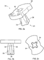
- a pin 20 of the fastener assembly 10 is illustrated in Figure 2 .
- the pin 20 comprises a head 22 having a hole or aperture 30 for receiving a suitable tool (not shown) to rotate the pin and lock or unlock the fastener assembly 10.
- the hole 30 may partially or completely pass through the depth of the head 22. Whilst the illustrated hole 30 has a hexagonal profile, it would be apparent that this is not essential and that other profiles for corresponding tools would be suitable for use with the present fastener assembly 10.
- the tool simply allows a user to rotate the pin 20 within the body 40 to lock or unlock the fastener assembly 10.
- the pin 20 further comprises an elongate portion 24 extending away from the head 22 along a longitudinal axis, the elongate portion 24 has four locking legs 26 extending away from the longitudinal axis in a direction substantially perpendicular direction to the longitudinal axis (e.g. centre axis of the pin 20).
- Each one of the locking legs 26 may comprise a ridge 28 formed thereon and which is configured to engage with a corresponding recess 58 on the body 40 (see Figure 3 ) when the fastener assembly 10 is in the locked configuration.
- the illustrated ridges 28 are formed as straight ridges, it would be apparent this was not essential and that other profiles would be suitable for use with the present fastener assembly 10. While the ridges 28 are illustrated adjacent a distal end of the elongate portion 24 it would be apparent this was not essential and the ridges 28 may be located at different positions and at different lengths along the abutment of locking legs 26.
- the four locking legs 26 extend in mutually (radially) perpendicular directions to one another so as to define a substantially cross-shaped cross sectional profile of the elongate portion 24. While four locking legs 26 are shown, it would be apparent that this was not essential and more or fewer than four locking legs 26 would be suitable for use with the present fastener assembly 10. Furthermore, while in some cases it is desirable for the fastener assembly 10 to have an equal number of locking legs 26 to retaining arms 46, this was not essential.
- the elongate portion 24 is also illustrated as having a tapered profile such that the cross sectional area of the elongate portion 24 increases when extending away from the head 22 of the pin 20. Adjacent pairs of locking legs 26 define a longitudinal recess 34, within which are located a pair of knobs 32 that are arranged so as to retain the pin 20 within the body 40 when the fastener assembly 10 is in the unlocked position.
- FIG. 3 illustrates an exemplary body 40 for use with the present fastener assembly 10.
- the body 40 has a head portion 42, an intermediate plate 44 and four arms 46 extending away from the head portion 42 in a direction parallel to a central longitudinal axis of the body 40.
- the head portion 42 has a central recess 52 for receiving the head 22 of the pin 20 when the fastener assembly 10 is assembled.
- a recess or space 50 is defined between the head portion 42 of the body 40 and the intermediate plate 44 which is for receiving a portion of a first panel 12.
- Each arm 46 is shown having an internal surface having a rib 56 disposed thereon. Each rib 56 is shown extending in a direction substantially parallel to that of the respective retaining arm 46, but it would be apparent this was not essential.
- Each rib 56 is also shown having a recess 58 formed therein. As described above, the recess 58 is configured to receive the corresponding ridge 28 formed on the abutment of the elongate portion 24 of the pin 20 to lock the fastener assembly 10 when in the locked configuration.
- the retaining arms 46 are also illustrated as pairs of opposed retaining arms arranged in a cross configuration that define a cavity 54 for receiving the elongate portion 24 of the pin 20.
- the resilient retaining arms 46 are adapted to resiliently deform towards and away from the central axis (so as to provide a bias back towards its undeformed position). This allows the retaining arms 46 to secure the pin 20 in place when the locking legs 26 engage with the retaining arms 46, i.e.
- the retaining arms 46 are abuttingly engaged with the corresponding ridges 28 preventing the retaining arms 46 from flexing (deforming) towards the central axis, which ensures the metal plate 5 remains clamped to the panel 12 (i.e. it cannot slide past the resilient retaining arms 46).
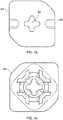
- Figure 4a illustrates a top-side view of the body 40.
- the head portion 42 has two stops 60 formed thereon which limit the rotation of the pin 20 within the body 40 by abutting the head 22 of the pin 20 when the pin 20 reaches a rotation limit, for example as shown in Figure 7a .
- a first rotation limit shown corresponds to when the locking legs 24 of the pin 20 are engaged with corresponding ribs 56 formed on each retaining arm 46.
- the rotation limit corresponds to when the ridges 28 on the locking legs 26 are engaged with the recess 58 formed within each rib 56. This corresponds to the locked configuration of the fastener assembly 10.
- a second rotation limit corresponds to when the locking legs 26 of the pin 20 are disengaged from the retaining arms 46 which is the unlocked configuration of the fastener assembly 10, for example as shown in Figure 7b .
- the head portion 42 has a central hole or aperture 62 formed therein for receiving the elongate portion 24 of the pin 20.
- the hole 62 has a profile that corresponding to the profile of the elongate portion 24. This allows the elongate portion 24 to pass through while preventing the head 22 of the pin 20 from passing through.
- Figure 5a illustrates a first panel 12, such as a plastic panel, having a recessed portion 14 and a hole or aperture 16 for receiving the fastener assembly 10.
- the hole 16 is formed within the recessed portion 14 of the panel 12 and is arranged such that the fastener assembly 10 is able to partially pass through the hole 16.
- Figure 5b when the fastener assembly 10 is assembled and mounted to the panel 12, the head portion 42 of the body 40 and the head 22 of the pin 20 are disposed on one side of the panel 12, while the retaining arms 46, intermediate plate 44 and elongate portion 24 are disposed on an other side of the panel 12.
- the arrangement illustrated in Figure 5b may be considered as a pre-assembled panel.
- Figure 6a illustrates an underside of the panel 12 and illustrates a second recess 18 formed in the underside of the panel 12.
- the fastener assembly 10 is inserted through the hole 16 until the head portion 42 of the body 40 abuts the panel 12 and the panel 12 is disposed between the intermediate plate 44 and the head portion 42.
- the fastener assembly 10 is rotated within the hole 16 until the panel 12 slides within the recess or space 50 formed between the intermediate plate 44 and the head portion 42. As shown in Figure 6b , a rotation of a quarter turn, i.e. approximately 45 degrees, results in parts of the intermediate plate 44 pressing against or engaging with the second recess 18 of the panel 12.
- the parts of the intermediate plate 44 that engage with the second recess 18 may be considered as tabs 45 that secure the body 40 to the panel 12.
- the fastener assembly 10 is held in position due to the contour and shape of the mounting hole 16. This design allows a tolerance of +/-1 mm in both directions. While the fastener assembly 10 is rotated by an angle of approximately 45 degrees to be secured to the panel in Figure 6b , it would be apparent this was not essential and that different profiles of the body 40 may correspond with other shapes of hole 16. Furthermore, it would be apparent that a pre-assembled panel may include a series of fastener assemblies 10 arranged in respective holes that are designed to fit with a second plate, for example, a metal plate 5.
- the pre-assembled panel may be subsequently pressed against the metal plate 5 and the retaining arms 46 of each of the fastener assemblies 10 may resiliently deform in order to pass through corresponding holes formed in the metal plate 5, such that the pre-assembled panel may be clipped onto the metal plate 5.
- An operator can then simply lock each of the fastener assemblies 10 to secure the metal plate 5 to the plastic panel 12 (see Figure 7a ).
- the fastener assembly 10 In the locked configuration, the fastener assembly 10 is prevented from moving out of engagement with the panel 12 and/or metal sheet 5.
- the resilient retaining arms 46 could be bent towards the central axis of the fastener assembly 10, which allows the cross-sectional area defined by the outer periphery of the retaining arms 46 to reduce such that the body 40 slides through the hole of the metal plate 5.
- the resilient retaining arms 46 are prevented from deflecting inwards and towards the central axis of the fastener assembly 10, thereby retaining the cross-sectional area defined by the retaining arms 46 and preventing the fastener assembly 10 from dis-engaging with either of the plastic panel 12 and/or the metal sheet 5 (i.e. cannot slide through respective holes of the metal plate 5 and panel 12).
Landscapes
- Engineering & Computer Science (AREA)
- General Engineering & Computer Science (AREA)
- Mechanical Engineering (AREA)
- Insertion Pins And Rivets (AREA)
- Connection Of Plates (AREA)
Abstract
Description
- The invention relates to a fastener system for coupling two structures, such as, for example, a plastic panel and a metal sheet. In particular, the present invention provides for a fastening solution for plastic panel(s) with a metal sheet (e.g. with a wide range in thickness of 0.7 mm to 2.0 mm), therefore, allowing a pre-assembly function of the plastic panel with relatively large tolerances in both axes (e.g. +/- 1.0 mm) so as to minimise required space, assembly weight, as well as, the time needed for the final assembly with the metal sheet.
- A rivet or scrivet may be used to fix a plastic panel to a metal sheet. However, such fasteners require assembly at the time of fixing the plastic panel to the metal sheet because of the need to position the rivet or scrivet through the two components and then fasten it (i.e. extract the pin from the rivet or wind the screw into the scrivet). In addition, a rivet or scrivet requires space if it were pre-assembled to one of the components, and in such a case, there is a risk of the rivet or scrivet breaking before it is fixed to the other component.
- Other known fasteners for fixing a plastic panel to a metal sheet include screwing solutions such as an expanding grommet. The expanding grommet may be pre-fixed (i.e. preinstalled) on the metal sheet or on the plastic panel. However, the tolerance ranges can be limited, and a metal screw is typically required to complete fixation, consequently, resulting in higher weight and assembly time.
- According to the present invention, there is provided a fastener for fixing a sheet component, the fastener comprising: a body comprising a pair of resiliently deformable arms arranged to extend through an opening in the sheet component during use, and a pin rotatably mounted within the body and comprising a pair of locking legs, the pin being rotatable between an unlocked position in which the retaining arms are deformable to pass through the opening in the sheet component, and a locked position in which the locking legs engage the retaining arms to restrict deformation of the retaining arms and secure the fastener to the sheet component.
- Each of the retaining arms may comprise a rib having a slot formed thereon. The slot may be configured to receive a respective locking leg of the pin upon rotation of the pin to the locked position.
- The head may be configured to be attached to a further sheet component such that the fastener is for fixing the sheet component to the further sheet component. For example, the body may further comprise a head portion and a tab axially spaced from the head portion such that a portion of the further sheet component is receivable between the head portion and the tab to attach the fastener to the further sheet component. In some examples, the tab is shaped such that the tab can pass through a shaped opening in the further sheet component and the body is rotatable to move the portion of the further sheet component between the head portion and the tab. The tab may be substantially square, and the opening in the further sheet component may be substantially square. The further sheet component may comprise a recess extending from the opening to receive the tab.
- Accordingly, the fastener can be pre-assembled with the further sheet component by attaching the body to the further sheet component using the tab. The pre-assembly can then be attached to the sheet component by passing the retaining arms through an opening of the sheet component and rotating the pin.
- The body may comprise a hole having a first cross-sectional profile. The locking legs may define a second cross-sectional profile corresponding to the first cross-sectional profile. In the unlocked position, the locking legs may be able to pass through the hole such that the pin is separable from the body. This advantageously allows the body to be mounted to the further sheet component independently of the pin. By providing a separable fastener, the retaining arms of the body may be pressed through a hole formed in the further sheet material by deforming as it passes through the hole, and snap back into position once secured to the further sheet component.
- The pin may comprise at least one knob arranged to engage with the body when the pin is in the unlocked position, so as to retain the pin within the body in the unlocked position. Thus, the pin can be secured to the body after the body is secured to the further sheet component by passing the pin through the hole in the body and by pressing the pin into position.
- In another example, the present invention provides a sheet component comprising a fastener as described above, the fastener being secured to the sheet component.
- In another example, a pre-assembled sheet is provided. The pre-assembled sheet comprises a sheet component having a hole formed therein, a fastener comprising a body having a head portion and a tab, the tab being arranged to pass through the hole such that a portion of the sheet component is disposed between the head portion and the tab upon rotation of the body within the hole. The fastener is secured to the sheet component due to the contour and shape of the hole in the sheet component and the corresponding shape of the head portion and the tab of the fastener. Preferably, the fastener is secured to the sheet component upon rotation of the body by approximately 45 degrees within the hole.
- Example embodiment(s) of the invention are illustrated in the accompanying drawings, in which:
-
Figure 1 illustrates an example embodiment of the rivet fastener assembly of the present invention (a) side view, and (b) cross-sectional side view when in use, i.e. coupling a plastic panel and metal sheet; -
Figure 2 illustrates the locking element (i.e. pin) of the rivet fastener assembly ofFigure 1 in (a) a perspective view, (b) a front view and (c) a top view; -
Figure 3 the rivet retainer element of the rivet fastener assembly ofFigure 1 in (a) a perspective view, (b) a front view and (c) a cross-sectional view; -
Figure 4 illustrates the rivet retainer element in (a) a top view and (b) a bottom view; -
Figure 5 illustrates a top view of (a) the mounting hole of a metal sheet and (b) the rivet fastener assembly installed into the mounting hole; -
Figure 6 illustrates a bottom view of (a) the mounting hole of a metal sheet and (b) the rivet fastener assembly installed into the mounting hole, and -
Figure 7 shows a top and bottom view of a schematic illustration of the installed rivet fastener assembly when moving the locking element (or pin) between (a) a locked position and (b) an unlocked position. - The described example embodiment relates to a fastener assembly for use with vehicle components, and particularly, a fastener assembly for fixing sheet components. However, the invention is not limited for use with vehicle components but may be used for any suitable fastening.
- Certain terminology is used in the following description for convenience only and is not limiting. The words 'right', 'left', 'lower', 'upper', 'front', 'rear', 'upward', 'down', 'downward', 'above' and 'below' designate directions in the drawings to which reference is made and are with respect to the described component when assembled and mounted (e.g. in situ). The words 'inner', 'inwardly' and 'outer', 'outwardly' refer to directions toward and away from, respectively, a designated centreline or a geometric centre of an element being described (e.g. central axis), the particular meaning being readily apparent from the context of the description.
- Further, as used herein, the terms 'connected', 'attached', 'coupled', 'mounted' are intended to include direct connections between two members without any other members interposed therebetween, as well as, indirect connections between members in which one or more other members are interposed therebetween. The terminology includes the words specifically mentioned above, derivatives thereof, and words of similar import.
- Further, unless otherwise specified, the use of ordinal adjectives, such as, 'first', 'second', 'third' etc. merely indicate that different instances of like objects are being referred to and are not intended to imply that the objects so described must be in a given sequence, either temporally, spatially, in ranking or in any other manner.
- Through the description and claims of this specification, the terms 'comprise' and 'contain', and variations thereof, are interpreted to mean 'including but not limited to', and they are not intended to (and do not) exclude other moieties, additives, components, integers or steps. Throughout the description and claims of this specification, the singular encompasses the plural unless the context otherwise requires. In particular, where the indefinite article is used, the specification is to be understood as contemplating plurality, as well as, singularity, unless the context requires otherwise.
- All of the features disclosed in this specification (including any accompanying claims, abstract and drawings), and/or all of the steps of any method or process so disclosed, may be combined in any combination, except combinations where at least some of such features and/or steps are mutually exclusive. The invention is not restricted to the details of any foregoing embodiments. The invention extends to any novel one, or any novel combination, of the features disclosed in this specification (including any accompanying claims, abstract or drawings), or to any novel one, or any novel combination, of the steps of any method or process so disclosed.
- As shown in
Figure 1 , afastener assembly 10 is formed of apin 20 and abody 40 that can selectively secure aplastic panel 12 to ametal sheet 5. One example of apin 20 of thefastener assembly 10 is illustrated inFigure 2 . Thepin 20 comprises ahead 22 having a hole oraperture 30 for receiving a suitable tool (not shown) to rotate the pin and lock or unlock thefastener assembly 10. Thehole 30 may partially or completely pass through the depth of thehead 22. Whilst the illustratedhole 30 has a hexagonal profile, it would be apparent that this is not essential and that other profiles for corresponding tools would be suitable for use with thepresent fastener assembly 10. The tool simply allows a user to rotate thepin 20 within thebody 40 to lock or unlock thefastener assembly 10. - The
pin 20 further comprises anelongate portion 24 extending away from thehead 22 along a longitudinal axis, theelongate portion 24 has fourlocking legs 26 extending away from the longitudinal axis in a direction substantially perpendicular direction to the longitudinal axis (e.g. centre axis of the pin 20). Each one of thelocking legs 26 may comprise aridge 28 formed thereon and which is configured to engage with acorresponding recess 58 on the body 40 (seeFigure 3 ) when thefastener assembly 10 is in the locked configuration. While the illustratedridges 28 are formed as straight ridges, it would be apparent this was not essential and that other profiles would be suitable for use with thepresent fastener assembly 10. While theridges 28 are illustrated adjacent a distal end of theelongate portion 24 it would be apparent this was not essential and theridges 28 may be located at different positions and at different lengths along the abutment of lockinglegs 26. - The four locking
legs 26 extend in mutually (radially) perpendicular directions to one another so as to define a substantially cross-shaped cross sectional profile of theelongate portion 24. While four lockinglegs 26 are shown, it would be apparent that this was not essential and more or fewer than four lockinglegs 26 would be suitable for use with thepresent fastener assembly 10. Furthermore, while in some cases it is desirable for thefastener assembly 10 to have an equal number of lockinglegs 26 to retainingarms 46, this was not essential. Theelongate portion 24 is also illustrated as having a tapered profile such that the cross sectional area of theelongate portion 24 increases when extending away from thehead 22 of thepin 20. Adjacent pairs of lockinglegs 26 define alongitudinal recess 34, within which are located a pair ofknobs 32 that are arranged so as to retain thepin 20 within thebody 40 when thefastener assembly 10 is in the unlocked position. -
Figure 3 illustrates anexemplary body 40 for use with thepresent fastener assembly 10. Thebody 40 has a head portion
42, anintermediate plate 44 and fourarms 46 extending away from thehead portion 42 in a direction parallel to a central longitudinal axis of thebody 40. Thehead portion 42 has acentral recess 52 for receiving thehead 22 of thepin 20 when thefastener assembly 10 is assembled. A recess orspace 50 is defined between thehead portion 42 of thebody 40 and theintermediate plate 44 which is for receiving a portion of afirst panel 12. Eacharm 46 is shown having an internal surface having arib 56 disposed thereon. Eachrib 56 is shown extending in a direction substantially parallel to that of therespective retaining arm 46, but it would be apparent this was not essential. Eachrib 56 is also shown having arecess 58 formed therein. As described above, therecess 58 is configured to receive thecorresponding ridge 28 formed on the abutment of theelongate portion 24 of thepin 20 to lock thefastener assembly 10 when in the locked configuration. The retainingarms 46 are also illustrated as pairs of opposed retaining arms arranged in a cross configuration that define acavity 54 for receiving theelongate portion 24 of thepin 20. The resilient retainingarms 46 are adapted to resiliently deform towards and away from the central axis (so as to provide a bias back towards its undeformed position). This allows the retainingarms 46 to secure thepin 20 in place when the lockinglegs 26 engage with the retainingarms 46, i.e. pushing the retainingarms 46 away from the central axis and creating a bias back towards the central axis. In the locked configuration, the retainingarms 46 are abuttingly engaged with the correspondingridges 28 preventing the retainingarms 46 from flexing (deforming) towards the central axis, which ensures themetal plate 5 remains clamped to the panel 12 (i.e. it cannot slide past the resilient retaining arms 46). -
Figure 4a illustrates a top-side view of thebody 40. As shown, thehead portion 42 has twostops 60 formed thereon which limit the rotation of thepin 20 within thebody 40 by abutting thehead 22 of thepin 20 when thepin 20 reaches a rotation limit, for example as shown inFigure 7a . A first rotation limit shown corresponds to when the lockinglegs 24 of thepin 20 are engaged withcorresponding ribs 56 formed on each retainingarm 46. Specifically, the rotation limit corresponds to when theridges 28 on the lockinglegs 26 are engaged with therecess 58 formed within eachrib 56. This corresponds to the locked configuration of thefastener assembly 10. A second rotation limit corresponds to when the lockinglegs 26 of thepin 20 are disengaged from the retainingarms 46 which is the unlocked configuration of thefastener assembly 10, for example as shown inFigure 7b . Thehead portion 42 has a central hole oraperture 62 formed therein for receiving theelongate portion 24 of thepin 20. As shown inFigures 4a and 4b , thehole 62 has a profile that corresponding to the profile of theelongate portion 24. This allows theelongate portion 24 to pass through while preventing thehead 22 of thepin 20 from passing through. -
Figure 5a illustrates afirst panel 12, such as a plastic panel, having a recessedportion 14 and a hole oraperture 16 for receiving thefastener assembly 10. Thehole 16 is formed within the recessedportion 14 of thepanel 12 and is arranged such that thefastener assembly 10 is able to partially pass through thehole 16. As shown inFigure 5b , when thefastener assembly 10 is assembled and mounted to thepanel 12, thehead portion 42 of thebody 40 and thehead 22 of thepin 20 are disposed on one side of thepanel 12, while the retainingarms 46,intermediate plate 44 andelongate portion 24 are disposed on an other side of thepanel 12. The arrangement illustrated inFigure 5b may be considered as a pre-assembled panel.Figure 6a illustrates an underside of thepanel 12 and illustrates asecond recess 18 formed in the underside of thepanel 12. - To prepare a pre-assembled panel, the
fastener assembly 10 is inserted through thehole 16 until thehead portion 42 of thebody 40 abuts thepanel 12 and thepanel 12 is disposed between theintermediate plate 44 and thehead portion 42. To secure thefastener assembly 10 to thepanel 12 and prepare a pre-assembled panel, thefastener assembly 10 is rotated within thehole 16 until thepanel 12 slides within the recess orspace 50 formed between theintermediate plate 44 and thehead portion 42. As shown inFigure 6b , a rotation of a quarter turn, i.e. approximately 45 degrees, results in parts of theintermediate plate 44 pressing against or engaging with thesecond recess 18 of thepanel 12. The parts of theintermediate plate 44 that engage with thesecond recess 18 may be considered astabs 45 that secure thebody 40 to thepanel 12. Thefastener assembly 10 is held in position due to the contour and shape of the mountinghole 16. This design allows a tolerance of +/-1 mm in both directions. While thefastener assembly 10 is rotated by an angle of approximately 45 degrees to be secured to the panel inFigure 6b , it would be apparent this was not essential and that different profiles of thebody 40 may correspond with other shapes ofhole 16. Furthermore, it would be apparent that a pre-assembled panel may include a series offastener assemblies 10 arranged in respective holes that are designed to fit with a second plate, for example, ametal plate 5. The pre-assembled panel may be subsequently pressed against themetal plate 5 and the retainingarms 46 of each of thefastener assemblies 10 may resiliently deform in order to pass through corresponding holes formed in themetal plate 5, such that the pre-assembled panel may be clipped onto themetal plate 5. An operator can then simply lock each of thefastener assemblies 10 to secure themetal plate 5 to the plastic panel 12 (seeFigure 7a ). - In the locked configuration, the
fastener assembly 10 is prevented from moving out of engagement with thepanel 12 and/ormetal sheet 5. When thepin 20 is in the unlocked position, the resilient retainingarms 46 could be bent towards the central axis of thefastener assembly 10, which allows the cross-sectional area defined by the outer periphery of the retainingarms 46 to reduce such that thebody 40 slides through the hole of themetal plate 5. When thepin 20 is in the locked position, the resilient retainingarms 46 are prevented from deflecting inwards and towards the central axis of thefastener assembly 10, thereby retaining the cross-sectional area defined by the retainingarms 46 and preventing thefastener assembly 10 from dis-engaging with either of theplastic panel 12 and/or the metal sheet 5 (i.e. cannot slide through respective holes of themetal plate 5 and panel 12). - It will be appreciated by persons skilled in the art that the above embodiment(s) have been described by way of example only and not in any limitative sense, and that various alterations and modifications are possible without departing from the scope of the invention as defined by the appended claims. Various modifications to the detailed designs as described above are possible, for example, variations may exist in shape, size, arrangement (i.e. a single unitary components or two separate components), assembly or the like.
Claims (7)
- A fastener for fixing a sheet component, the fastener comprising:a body comprising a pair of resiliently deformable arms arranged to extend through an opening in the sheet component during use, anda pin rotatably mounted within the body and comprising a pair of locking legs, the pin being rotatable between:an unlocked position, in which the retaining arms are deformable to pass through the opening in the sheet component, anda locked position, in which the locking legs engage the retaining arms to restrict deformation of the retaining arms and secure the fastener to the sheet component.
- A fastener according to claim 1, wherein each of the retaining arms comprise a rib having a slot formed thereon, and wherein the slot is configured to receive a respective locking leg of the pin upon rotation of the pin to the locked position.
- A fastener according to claim 1 or claim 2, wherein the body is configured to be attached to a further sheet component such that the fastener is for fixing the sheet component to the further sheet component.
- A fastener according to claim 3, wherein the body comprises a head portion and a tab axially spaced from the head portion such that a portion of the further sheet component is receivable between the head portion and the tab so as to attach the fastener to the further sheet component.
- A fastener according to any preceding claim, wherein the body comprises a hole having a first cross-sectional profile, wherein the locking legs define a second cross-sectional profile corresponding to the first cross-sectional profile, and wherein, in the unlocked position, the locking legs can pass through the hole for assembly of the fastener.
- A fastener according to any preceding claim, wherein the pin further comprises at least one knob arranged to engage with the body when the pin is in the unlocked position, so as to retain the pin within the body in the unlocked position.
- A sheet component comprising a fastener according to any preceding claim secured thereto.
Priority Applications (2)
| Application Number | Priority Date | Filing Date | Title |
|---|---|---|---|
| US17/333,841 US11692567B2 (en) | 2020-06-03 | 2021-05-28 | Fastener |
| CN202110590819.8A CN113819121B (en) | 2020-06-03 | 2021-05-28 | Fastening piece |
Applications Claiming Priority (2)
| Application Number | Priority Date | Filing Date | Title |
|---|---|---|---|
| EP20178073 | 2020-06-03 | ||
| EP20180606 | 2020-06-17 |
Publications (2)
| Publication Number | Publication Date |
|---|---|
| EP3919762A1 true EP3919762A1 (en) | 2021-12-08 |
| EP3919762B1 EP3919762B1 (en) | 2023-11-22 |
Family
ID=75825529
Family Applications (1)
| Application Number | Title | Priority Date | Filing Date |
|---|---|---|---|
| EP21172266.5A Active EP3919762B1 (en) | 2020-06-03 | 2021-05-05 | Fastener |
Country Status (3)
| Country | Link |
|---|---|
| US (1) | US11692567B2 (en) |
| EP (1) | EP3919762B1 (en) |
| CN (1) | CN113819121B (en) |
Families Citing this family (8)
| Publication number | Priority date | Publication date | Assignee | Title |
|---|---|---|---|---|
| US11427989B2 (en) * | 2019-11-14 | 2022-08-30 | Caterpillar Inc. | Retainer sleeve design with external ribs |
| DE102020110407B4 (en) * | 2020-04-16 | 2026-04-23 | Illinois Tool Works Inc. | Fastening device for attaching a component to a supporting component |
| US20240263433A1 (en) * | 2022-05-18 | 2024-08-08 | Jeffrey Scott Crevier | Suction cup article for a urinal screen |
| CN114961430B (en) * | 2022-06-14 | 2023-11-28 | 安徽克琳黛尔智能家居有限公司 | Door handle structure with quick assembly disassembly function and shower room |
| CN120344775A (en) * | 2022-12-14 | 2025-07-18 | 莱克普蒂姆矿业有限公司 | Wear member retaining assembly |
| EP4528115A1 (en) * | 2023-09-21 | 2025-03-26 | Illinois Tool Works Inc. | Torsion clip |
| AU2024351695A1 (en) * | 2023-09-28 | 2026-04-30 | Makuri Technology Pte. Ltd. | A fastener for a one-sided bolt system |
| US20250361899A1 (en) * | 2024-05-24 | 2025-11-27 | The Boeing Company | Twist-lock fasteners, assemblies, and methods for fastening |
Citations (2)
| Publication number | Priority date | Publication date | Assignee | Title |
|---|---|---|---|---|
| FR2561325A3 (en) * | 1984-03-19 | 1985-09-20 | Usm Corp | Clip composed of an injected plastic part |
| US6196756B1 (en) * | 1997-03-24 | 2001-03-06 | Illinois Tool Works Inc. | Releasable fastener assembly for preferred use in a vehicle |
Family Cites Families (34)
| Publication number | Priority date | Publication date | Assignee | Title |
|---|---|---|---|---|
| JPS5934732Y2 (en) * | 1980-11-05 | 1984-09-26 | 株式会社ニフコ | Parts mounting structure |
| JPS57155190A (en) * | 1981-03-21 | 1982-09-25 | Shiyunyuu So | Metal fitting for channel type lashing |
| US4527760A (en) * | 1983-06-29 | 1985-07-09 | Super Glue Corporation | Adjustable clip system |
| JPS6414912U (en) * | 1987-07-16 | 1989-01-25 | ||
| JPH0247414U (en) * | 1988-09-29 | 1990-03-30 | ||
| JP2873909B2 (en) * | 1994-03-10 | 1999-03-24 | 株式会社ニフコ | Board stop |
| US5448804A (en) * | 1994-04-13 | 1995-09-12 | The Standard Products Company | Retention clip |
| JP3297972B2 (en) * | 1995-04-17 | 2002-07-02 | 株式会社パイオラックス | Securing clip |
| US5604958A (en) * | 1995-11-06 | 1997-02-25 | National Molding Corp. | Attachment system for backpacks, vests, belts and the like |
| US6108944A (en) * | 1996-01-17 | 2000-08-29 | Macneill Engineering Company, Inc. | Quick-release connector |
| US5975820A (en) * | 1998-11-03 | 1999-11-02 | Illinois Tool Works Inc. | Two-piece pin and grommet |
| FR2791214B1 (en) * | 1999-03-17 | 2001-06-01 | Mitsubishi Electric France | RELEASABLE COUPLING OF A SUSPENSION Nipple ON A WALL OF A MOBILE TELEPHONE |
| US6594870B1 (en) * | 2001-01-22 | 2003-07-22 | Johnson Controls Technology Company | Panel fastener |
| US6612795B2 (en) * | 2001-09-26 | 2003-09-02 | Illinois Tool Works Inc. | Quarter turn panel fastener |
| US7073231B2 (en) * | 2002-09-13 | 2006-07-11 | Southco, Inc. | Tether clip system |
| US7017239B2 (en) * | 2002-12-17 | 2006-03-28 | Illinois Tool Works Inc. | Component connection system |
| FR2853367B1 (en) * | 2003-04-03 | 2005-06-24 | Lisi Automotive Rapid | FIXING DEVICE, IN PARTICULAR FOR MAINTAINING A STACK OF AT LEAST TWO PANELS |
| US6929226B1 (en) * | 2003-08-11 | 2005-08-16 | The United States Of America As Represented By The Secretary Of The Army | Twist lock mounting system |
| US6955515B2 (en) * | 2003-12-09 | 2005-10-18 | International Business Machines Corporation | Locking turn pin |
| TWM273242U (en) * | 2005-03-16 | 2005-08-21 | Button Int Co Ltd | Rotational safety buckle |
| US7748089B2 (en) * | 2008-01-15 | 2010-07-06 | Illinois Tool Works Inc. | Auger clip assembly |
| DE102008061613A1 (en) * | 2008-12-11 | 2010-07-01 | Trw Automotive Electronics & Components Gmbh | Device for fastening a vehicle interior trim |
| ITTO20090398A1 (en) * | 2009-05-26 | 2010-11-27 | Illinois Tool Works | CLIP WITH A SELF-LOCKING FIXING DEVICE TO A VEHICLE BODYWORK ELEMENT |
| CA2768039C (en) * | 2009-07-24 | 2017-09-12 | Pem Management, Inc. | Quick acting panel fastener |
| US8677573B2 (en) * | 2011-03-24 | 2014-03-25 | Ford Global Technologies, Llc | Two stage serviceable safety clip |
| DE102011107080A1 (en) * | 2011-07-11 | 2013-01-17 | Trw Automotive Electronics & Components Gmbh | Adapter, assembly with adapter and method for assembling such an assembly |
| FR2981135B1 (en) * | 2011-10-11 | 2013-11-15 | Itw De France | FASTENING DEVICE FOR FASTENING A PANEL TO A WALL WITH HIGH BREAK RESISTANCE AND ASSEMBLY COMPRISING SUCH A DEVICE |
| US9982699B2 (en) * | 2012-11-15 | 2018-05-29 | Illinois Tool Works Inc. | Energy absorption rotatable fastener |
| JP6054192B2 (en) * | 2013-01-31 | 2016-12-27 | 大和化成工業株式会社 | Clip mounting structure |
| US8851551B1 (en) * | 2013-06-12 | 2014-10-07 | Macneil Ip Llc | Vehicle floor cover retention system and device |
| US9756930B2 (en) * | 2015-04-28 | 2017-09-12 | Axon Enterprise, Inc. | Methods and apparatus for a low-profile coupler |
| DE102016008022A1 (en) * | 2016-07-04 | 2018-01-04 | A.RAYMOND et Cie. SCS | A clip having a head and a shaft extending along a longitudinal axis from the head |
| CN112081807A (en) * | 2019-06-14 | 2020-12-15 | 伊利诺斯工具制品有限公司 | Fastening piece |
| US10989239B2 (en) * | 2019-07-11 | 2021-04-27 | Newfrey Llc | Two-piece fastener assembly |
-
2021
- 2021-05-05 EP EP21172266.5A patent/EP3919762B1/en active Active
- 2021-05-28 US US17/333,841 patent/US11692567B2/en active Active
- 2021-05-28 CN CN202110590819.8A patent/CN113819121B/en active Active
Patent Citations (2)
| Publication number | Priority date | Publication date | Assignee | Title |
|---|---|---|---|---|
| FR2561325A3 (en) * | 1984-03-19 | 1985-09-20 | Usm Corp | Clip composed of an injected plastic part |
| US6196756B1 (en) * | 1997-03-24 | 2001-03-06 | Illinois Tool Works Inc. | Releasable fastener assembly for preferred use in a vehicle |
Also Published As
| Publication number | Publication date |
|---|---|
| EP3919762B1 (en) | 2023-11-22 |
| US11692567B2 (en) | 2023-07-04 |
| CN113819121A (en) | 2021-12-21 |
| US20210381536A1 (en) | 2021-12-09 |
| CN113819121B (en) | 2026-05-01 |
Similar Documents
| Publication | Publication Date | Title |
|---|---|---|
| EP3919762B1 (en) | Fastener | |
| EP1354108B1 (en) | Handrail and end member assembly | |
| EP0892892B1 (en) | Blind snap mounted clip fastener | |
| JPS5934732Y2 (en) | Parts mounting structure | |
| US8627552B2 (en) | Multicontact adaptive fastener clip | |
| US4354566A (en) | Radiator grille fixing structure | |
| US20060242802A1 (en) | Fastener and fastened assembly | |
| WO2000052346A1 (en) | Snap-in fastener for panels | |
| US10036410B2 (en) | Article for blind fastening to a support | |
| US10670059B2 (en) | High retention force fastener | |
| US11560104B2 (en) | Spring clip | |
| EP2596994A1 (en) | Fascia coupling bracket | |
| EP3812599B1 (en) | A fastener and a part having the same | |
| US11661964B2 (en) | Fastener | |
| CN107401542A (en) | The locking retainer system of automobile assembling | |
| CN110062850A (en) | Fastener assembly | |
| EP0754600A1 (en) | Improved spring retainer air bag mounting device | |
| US10934758B2 (en) | Desensitized adjustable bumper | |
| WO2017218063A1 (en) | Rotationally-constrainable compensation nut fastener assembly | |
| US6959943B2 (en) | Deflectable airbag housing mounting tabs | |
| US11486423B2 (en) | Linear latching systems and methods | |
| EP3889447B1 (en) | A fastener | |
| EP4015845A1 (en) | A fastener assembly | |
| EP1484513B1 (en) | Resilient fastener with means for preventing rotation | |
| US12228169B2 (en) | System and method for mounting a panel to an electrical cabinet |
Legal Events
| Date | Code | Title | Description |
|---|---|---|---|
| PUAI | Public reference made under article 153(3) epc to a published international application that has entered the european phase |
Free format text: ORIGINAL CODE: 0009012 |
|
| STAA | Information on the status of an ep patent application or granted ep patent |
Free format text: STATUS: THE APPLICATION HAS BEEN PUBLISHED |
|
| AK | Designated contracting states |
Kind code of ref document: A1 Designated state(s): AL AT BE BG CH CY CZ DE DK EE ES FI FR GB GR HR HU IE IS IT LI LT LU LV MC MK MT NL NO PL PT RO RS SE SI SK SM TR |
|
| B565 | Issuance of search results under rule 164(2) epc |
Effective date: 20210930 |
|
| STAA | Information on the status of an ep patent application or granted ep patent |
Free format text: STATUS: REQUEST FOR EXAMINATION WAS MADE |
|
| 17P | Request for examination filed |
Effective date: 20220601 |
|
| RBV | Designated contracting states (corrected) |
Designated state(s): AL AT BE BG CH CY CZ DE DK EE ES FI FR GB GR HR HU IE IS IT LI LT LU LV MC MK MT NL NO PL PT RO RS SE SI SK SM TR |
|
| GRAP | Despatch of communication of intention to grant a patent |
Free format text: ORIGINAL CODE: EPIDOSNIGR1 |
|
| STAA | Information on the status of an ep patent application or granted ep patent |
Free format text: STATUS: GRANT OF PATENT IS INTENDED |
|
| RIC1 | Information provided on ipc code assigned before grant |
Ipc: F16B 5/06 20060101ALI20230620BHEP Ipc: F16B 2/22 20060101ALI20230620BHEP Ipc: F16B 21/02 20060101AFI20230620BHEP |
|
| INTG | Intention to grant announced |
Effective date: 20230713 |
|
| P01 | Opt-out of the competence of the unified patent court (upc) registered |
Effective date: 20230727 |
|
| GRAS | Grant fee paid |
Free format text: ORIGINAL CODE: EPIDOSNIGR3 |
|
| GRAA | (expected) grant |
Free format text: ORIGINAL CODE: 0009210 |
|
| STAA | Information on the status of an ep patent application or granted ep patent |
Free format text: STATUS: THE PATENT HAS BEEN GRANTED |
|
| AK | Designated contracting states |
Kind code of ref document: B1 Designated state(s): AL AT BE BG CH CY CZ DE DK EE ES FI FR GB GR HR HU IE IS IT LI LT LU LV MC MK MT NL NO PL PT RO RS SE SI SK SM TR |
|
| REG | Reference to a national code |
Ref country code: GB Ref legal event code: FG4D |
|
| REG | Reference to a national code |
Ref country code: CH Ref legal event code: EP Ref country code: DE Ref legal event code: R096 Ref document number: 602021006963 Country of ref document: DE |
|
| REG | Reference to a national code |
Ref country code: IE Ref legal event code: FG4D |
|
| REG | Reference to a national code |
Ref country code: LT Ref legal event code: MG9D |
|
| REG | Reference to a national code |
Ref country code: NL Ref legal event code: MP Effective date: 20231122 |
|
| PG25 | Lapsed in a contracting state [announced via postgrant information from national office to epo] |
Ref country code: GR Free format text: LAPSE BECAUSE OF FAILURE TO SUBMIT A TRANSLATION OF THE DESCRIPTION OR TO PAY THE FEE WITHIN THE PRESCRIBED TIME-LIMIT Effective date: 20240223 |
|
| PG25 | Lapsed in a contracting state [announced via postgrant information from national office to epo] |
Ref country code: IS Free format text: LAPSE BECAUSE OF FAILURE TO SUBMIT A TRANSLATION OF THE DESCRIPTION OR TO PAY THE FEE WITHIN THE PRESCRIBED TIME-LIMIT Effective date: 20240322 |
|
| PG25 | Lapsed in a contracting state [announced via postgrant information from national office to epo] |
Ref country code: LT Free format text: LAPSE BECAUSE OF FAILURE TO SUBMIT A TRANSLATION OF THE DESCRIPTION OR TO PAY THE FEE WITHIN THE PRESCRIBED TIME-LIMIT Effective date: 20231122 |
|
| REG | Reference to a national code |
Ref country code: AT Ref legal event code: MK05 Ref document number: 1634095 Country of ref document: AT Kind code of ref document: T Effective date: 20231122 |
|
| PG25 | Lapsed in a contracting state [announced via postgrant information from national office to epo] |
Ref country code: NL Free format text: LAPSE BECAUSE OF FAILURE TO SUBMIT A TRANSLATION OF THE DESCRIPTION OR TO PAY THE FEE WITHIN THE PRESCRIBED TIME-LIMIT Effective date: 20231122 |
|
| PG25 | Lapsed in a contracting state [announced via postgrant information from national office to epo] |
Ref country code: AT Free format text: LAPSE BECAUSE OF FAILURE TO SUBMIT A TRANSLATION OF THE DESCRIPTION OR TO PAY THE FEE WITHIN THE PRESCRIBED TIME-LIMIT Effective date: 20231122 |
|
| PG25 | Lapsed in a contracting state [announced via postgrant information from national office to epo] |
Ref country code: ES Free format text: LAPSE BECAUSE OF FAILURE TO SUBMIT A TRANSLATION OF THE DESCRIPTION OR TO PAY THE FEE WITHIN THE PRESCRIBED TIME-LIMIT Effective date: 20231122 |
|
| PG25 | Lapsed in a contracting state [announced via postgrant information from national office to epo] |
Ref country code: NL Free format text: LAPSE BECAUSE OF FAILURE TO SUBMIT A TRANSLATION OF THE DESCRIPTION OR TO PAY THE FEE WITHIN THE PRESCRIBED TIME-LIMIT Effective date: 20231122 Ref country code: LT Free format text: LAPSE BECAUSE OF FAILURE TO SUBMIT A TRANSLATION OF THE DESCRIPTION OR TO PAY THE FEE WITHIN THE PRESCRIBED TIME-LIMIT Effective date: 20231122 Ref country code: IS Free format text: LAPSE BECAUSE OF FAILURE TO SUBMIT A TRANSLATION OF THE DESCRIPTION OR TO PAY THE FEE WITHIN THE PRESCRIBED TIME-LIMIT Effective date: 20240322 Ref country code: GR Free format text: LAPSE BECAUSE OF FAILURE TO SUBMIT A TRANSLATION OF THE DESCRIPTION OR TO PAY THE FEE WITHIN THE PRESCRIBED TIME-LIMIT Effective date: 20240223 Ref country code: ES Free format text: LAPSE BECAUSE OF FAILURE TO SUBMIT A TRANSLATION OF THE DESCRIPTION OR TO PAY THE FEE WITHIN THE PRESCRIBED TIME-LIMIT Effective date: 20231122 Ref country code: BG Free format text: LAPSE BECAUSE OF FAILURE TO SUBMIT A TRANSLATION OF THE DESCRIPTION OR TO PAY THE FEE WITHIN THE PRESCRIBED TIME-LIMIT Effective date: 20240222 Ref country code: AT Free format text: LAPSE BECAUSE OF FAILURE TO SUBMIT A TRANSLATION OF THE DESCRIPTION OR TO PAY THE FEE WITHIN THE PRESCRIBED TIME-LIMIT Effective date: 20231122 Ref country code: PT Free format text: LAPSE BECAUSE OF FAILURE TO SUBMIT A TRANSLATION OF THE DESCRIPTION OR TO PAY THE FEE WITHIN THE PRESCRIBED TIME-LIMIT Effective date: 20240322 |
|
| PG25 | Lapsed in a contracting state [announced via postgrant information from national office to epo] |
Ref country code: SE Free format text: LAPSE BECAUSE OF FAILURE TO SUBMIT A TRANSLATION OF THE DESCRIPTION OR TO PAY THE FEE WITHIN THE PRESCRIBED TIME-LIMIT Effective date: 20231122 Ref country code: RS Free format text: LAPSE BECAUSE OF FAILURE TO SUBMIT A TRANSLATION OF THE DESCRIPTION OR TO PAY THE FEE WITHIN THE PRESCRIBED TIME-LIMIT Effective date: 20231122 Ref country code: PL Free format text: LAPSE BECAUSE OF FAILURE TO SUBMIT A TRANSLATION OF THE DESCRIPTION OR TO PAY THE FEE WITHIN THE PRESCRIBED TIME-LIMIT Effective date: 20231122 Ref country code: NO Free format text: LAPSE BECAUSE OF FAILURE TO SUBMIT A TRANSLATION OF THE DESCRIPTION OR TO PAY THE FEE WITHIN THE PRESCRIBED TIME-LIMIT Effective date: 20240222 Ref country code: LV Free format text: LAPSE BECAUSE OF FAILURE TO SUBMIT A TRANSLATION OF THE DESCRIPTION OR TO PAY THE FEE WITHIN THE PRESCRIBED TIME-LIMIT Effective date: 20231122 Ref country code: HR Free format text: LAPSE BECAUSE OF FAILURE TO SUBMIT A TRANSLATION OF THE DESCRIPTION OR TO PAY THE FEE WITHIN THE PRESCRIBED TIME-LIMIT Effective date: 20231122 |
|
| PG25 | Lapsed in a contracting state [announced via postgrant information from national office to epo] |
Ref country code: DK Free format text: LAPSE BECAUSE OF FAILURE TO SUBMIT A TRANSLATION OF THE DESCRIPTION OR TO PAY THE FEE WITHIN THE PRESCRIBED TIME-LIMIT Effective date: 20231122 |
|
| PG25 | Lapsed in a contracting state [announced via postgrant information from national office to epo] |
Ref country code: CZ Free format text: LAPSE BECAUSE OF FAILURE TO SUBMIT A TRANSLATION OF THE DESCRIPTION OR TO PAY THE FEE WITHIN THE PRESCRIBED TIME-LIMIT Effective date: 20231122 |
|
| PG25 | Lapsed in a contracting state [announced via postgrant information from national office to epo] |
Ref country code: SK Free format text: LAPSE BECAUSE OF FAILURE TO SUBMIT A TRANSLATION OF THE DESCRIPTION OR TO PAY THE FEE WITHIN THE PRESCRIBED TIME-LIMIT Effective date: 20231122 |
|
| PG25 | Lapsed in a contracting state [announced via postgrant information from national office to epo] |
Ref country code: SM Free format text: LAPSE BECAUSE OF FAILURE TO SUBMIT A TRANSLATION OF THE DESCRIPTION OR TO PAY THE FEE WITHIN THE PRESCRIBED TIME-LIMIT Effective date: 20231122 Ref country code: SK Free format text: LAPSE BECAUSE OF FAILURE TO SUBMIT A TRANSLATION OF THE DESCRIPTION OR TO PAY THE FEE WITHIN THE PRESCRIBED TIME-LIMIT Effective date: 20231122 Ref country code: RO Free format text: LAPSE BECAUSE OF FAILURE TO SUBMIT A TRANSLATION OF THE DESCRIPTION OR TO PAY THE FEE WITHIN THE PRESCRIBED TIME-LIMIT Effective date: 20231122 Ref country code: IT Free format text: LAPSE BECAUSE OF FAILURE TO SUBMIT A TRANSLATION OF THE DESCRIPTION OR TO PAY THE FEE WITHIN THE PRESCRIBED TIME-LIMIT Effective date: 20231122 Ref country code: EE Free format text: LAPSE BECAUSE OF FAILURE TO SUBMIT A TRANSLATION OF THE DESCRIPTION OR TO PAY THE FEE WITHIN THE PRESCRIBED TIME-LIMIT Effective date: 20231122 Ref country code: DK Free format text: LAPSE BECAUSE OF FAILURE TO SUBMIT A TRANSLATION OF THE DESCRIPTION OR TO PAY THE FEE WITHIN THE PRESCRIBED TIME-LIMIT Effective date: 20231122 Ref country code: CZ Free format text: LAPSE BECAUSE OF FAILURE TO SUBMIT A TRANSLATION OF THE DESCRIPTION OR TO PAY THE FEE WITHIN THE PRESCRIBED TIME-LIMIT Effective date: 20231122 |
|
| REG | Reference to a national code |
Ref country code: DE Ref legal event code: R097 Ref document number: 602021006963 Country of ref document: DE |
|
| PLBE | No opposition filed within time limit |
Free format text: ORIGINAL CODE: 0009261 |
|
| STAA | Information on the status of an ep patent application or granted ep patent |
Free format text: STATUS: NO OPPOSITION FILED WITHIN TIME LIMIT |
|
| PG25 | Lapsed in a contracting state [announced via postgrant information from national office to epo] |
Ref country code: SI Free format text: LAPSE BECAUSE OF FAILURE TO SUBMIT A TRANSLATION OF THE DESCRIPTION OR TO PAY THE FEE WITHIN THE PRESCRIBED TIME-LIMIT Effective date: 20231122 |
|
| 26N | No opposition filed |
Effective date: 20240823 |
|
| PG25 | Lapsed in a contracting state [announced via postgrant information from national office to epo] |
Ref country code: SI Free format text: LAPSE BECAUSE OF FAILURE TO SUBMIT A TRANSLATION OF THE DESCRIPTION OR TO PAY THE FEE WITHIN THE PRESCRIBED TIME-LIMIT Effective date: 20231122 |
|
| REG | Reference to a national code |
Ref country code: DE Ref legal event code: R119 Ref document number: 602021006963 Country of ref document: DE |
|
| REG | Reference to a national code |
Ref country code: CH Ref legal event code: PL |
|
| PG25 | Lapsed in a contracting state [announced via postgrant information from national office to epo] |
Ref country code: MC Free format text: LAPSE BECAUSE OF FAILURE TO SUBMIT A TRANSLATION OF THE DESCRIPTION OR TO PAY THE FEE WITHIN THE PRESCRIBED TIME-LIMIT Effective date: 20231122 |
|
| PG25 | Lapsed in a contracting state [announced via postgrant information from national office to epo] |
Ref country code: LU Free format text: LAPSE BECAUSE OF NON-PAYMENT OF DUE FEES Effective date: 20240505 |
|
| PG25 | Lapsed in a contracting state [announced via postgrant information from national office to epo] |
Ref country code: MC Free format text: LAPSE BECAUSE OF FAILURE TO SUBMIT A TRANSLATION OF THE DESCRIPTION OR TO PAY THE FEE WITHIN THE PRESCRIBED TIME-LIMIT Effective date: 20231122 Ref country code: LU Free format text: LAPSE BECAUSE OF NON-PAYMENT OF DUE FEES Effective date: 20240505 Ref country code: CH Free format text: LAPSE BECAUSE OF NON-PAYMENT OF DUE FEES Effective date: 20240531 |
|
| REG | Reference to a national code |
Ref country code: BE Ref legal event code: MM Effective date: 20240531 |
|
| PG25 | Lapsed in a contracting state [announced via postgrant information from national office to epo] |
Ref country code: DE Free format text: LAPSE BECAUSE OF NON-PAYMENT OF DUE FEES Effective date: 20241203 |
|
| PG25 | Lapsed in a contracting state [announced via postgrant information from national office to epo] |
Ref country code: IE Free format text: LAPSE BECAUSE OF NON-PAYMENT OF DUE FEES Effective date: 20240505 |
|
| PG25 | Lapsed in a contracting state [announced via postgrant information from national office to epo] |
Ref country code: BE Free format text: LAPSE BECAUSE OF NON-PAYMENT OF DUE FEES Effective date: 20240531 |
|
| PG25 | Lapsed in a contracting state [announced via postgrant information from national office to epo] |
Ref country code: FR Free format text: LAPSE BECAUSE OF NON-PAYMENT OF DUE FEES Effective date: 20240531 |
|
| PG25 | Lapsed in a contracting state [announced via postgrant information from national office to epo] |
Ref country code: CY Free format text: LAPSE BECAUSE OF FAILURE TO SUBMIT A TRANSLATION OF THE DESCRIPTION OR TO PAY THE FEE WITHIN THE PRESCRIBED TIME-LIMIT; INVALID AB INITIO Effective date: 20210505 |
|
| PG25 | Lapsed in a contracting state [announced via postgrant information from national office to epo] |
Ref country code: HU Free format text: LAPSE BECAUSE OF FAILURE TO SUBMIT A TRANSLATION OF THE DESCRIPTION OR TO PAY THE FEE WITHIN THE PRESCRIBED TIME-LIMIT; INVALID AB INITIO Effective date: 20210505 |
|
| PG25 | Lapsed in a contracting state [announced via postgrant information from national office to epo] |
Ref country code: FI Free format text: LAPSE BECAUSE OF FAILURE TO SUBMIT A TRANSLATION OF THE DESCRIPTION OR TO PAY THE FEE WITHIN THE PRESCRIBED TIME-LIMIT Effective date: 20231122 |
|
| GBPC | Gb: european patent ceased through non-payment of renewal fee |
Effective date: 20250505 |
|
| PG25 | Lapsed in a contracting state [announced via postgrant information from national office to epo] |
Ref country code: GB Free format text: LAPSE BECAUSE OF NON-PAYMENT OF DUE FEES Effective date: 20250505 |