EP3919690A1 - Swivel joint for construction machine - Google Patents
Swivel joint for construction machine Download PDFInfo
- Publication number
- EP3919690A1 EP3919690A1 EP20774000.2A EP20774000A EP3919690A1 EP 3919690 A1 EP3919690 A1 EP 3919690A1 EP 20774000 A EP20774000 A EP 20774000A EP 3919690 A1 EP3919690 A1 EP 3919690A1
- Authority
- EP
- European Patent Office
- Prior art keywords
- rod
- slewing
- stem
- cover
- swivel joint
- Prior art date
- Legal status (The legal status is an assumption and is not a legal conclusion. Google has not performed a legal analysis and makes no representation as to the accuracy of the status listed.)
- Granted
Links
Images





Classifications
-
- E—FIXED CONSTRUCTIONS
- E02—HYDRAULIC ENGINEERING; FOUNDATIONS; SOIL SHIFTING
- E02F—DREDGING; SOIL-SHIFTING
- E02F9/00—Component parts of dredgers or soil-shifting machines, not restricted to one of the kinds covered by groups E02F3/00 - E02F7/00
- E02F9/08—Superstructures; Supports for superstructures
- E02F9/10—Supports for movable superstructures mounted on travelling or walking gears or on other superstructures
- E02F9/12—Slewing or traversing gears
- E02F9/121—Turntables, i.e. structure rotatable about 360°
- E02F9/126—Lubrication systems
-
- E—FIXED CONSTRUCTIONS
- E02—HYDRAULIC ENGINEERING; FOUNDATIONS; SOIL SHIFTING
- E02F—DREDGING; SOIL-SHIFTING
- E02F9/00—Component parts of dredgers or soil-shifting machines, not restricted to one of the kinds covered by groups E02F3/00 - E02F7/00
- E02F9/006—Pivot joint assemblies
-
- E—FIXED CONSTRUCTIONS
- E02—HYDRAULIC ENGINEERING; FOUNDATIONS; SOIL SHIFTING
- E02F—DREDGING; SOIL-SHIFTING
- E02F9/00—Component parts of dredgers or soil-shifting machines, not restricted to one of the kinds covered by groups E02F3/00 - E02F7/00
- E02F9/08—Superstructures; Supports for superstructures
- E02F9/10—Supports for movable superstructures mounted on travelling or walking gears or on other superstructures
- E02F9/12—Slewing or traversing gears
- E02F9/121—Turntables, i.e. structure rotatable about 360°
-
- E—FIXED CONSTRUCTIONS
- E02—HYDRAULIC ENGINEERING; FOUNDATIONS; SOIL SHIFTING
- E02F—DREDGING; SOIL-SHIFTING
- E02F9/00—Component parts of dredgers or soil-shifting machines, not restricted to one of the kinds covered by groups E02F3/00 - E02F7/00
- E02F9/20—Drives; Control devices
- E02F9/22—Hydraulic or pneumatic drives
- E02F9/2264—Arrangements or adaptations of elements for hydraulic drives
- E02F9/2275—Hoses and supports therefor and protection therefor
-
- E—FIXED CONSTRUCTIONS
- E02—HYDRAULIC ENGINEERING; FOUNDATIONS; SOIL SHIFTING
- E02F—DREDGING; SOIL-SHIFTING
- E02F9/00—Component parts of dredgers or soil-shifting machines, not restricted to one of the kinds covered by groups E02F3/00 - E02F7/00
- E02F9/26—Indicating devices
-
- E—FIXED CONSTRUCTIONS
- E02—HYDRAULIC ENGINEERING; FOUNDATIONS; SOIL SHIFTING
- E02F—DREDGING; SOIL-SHIFTING
- E02F9/00—Component parts of dredgers or soil-shifting machines, not restricted to one of the kinds covered by groups E02F3/00 - E02F7/00
- E02F9/26—Indicating devices
- E02F9/264—Sensors and their calibration for indicating the position of the work tool
-
- F—MECHANICAL ENGINEERING; LIGHTING; HEATING; WEAPONS; BLASTING
- F16—ENGINEERING ELEMENTS AND UNITS; GENERAL MEASURES FOR PRODUCING AND MAINTAINING EFFECTIVE FUNCTIONING OF MACHINES OR INSTALLATIONS; THERMAL INSULATION IN GENERAL
- F16L—PIPES; JOINTS OR FITTINGS FOR PIPES; SUPPORTS FOR PIPES, CABLES OR PROTECTIVE TUBING; MEANS FOR THERMAL INSULATION IN GENERAL
- F16L27/00—Adjustable joints; Joints allowing movement
- F16L27/08—Adjustable joints; Joints allowing movement allowing adjustment or movement only about the axis of one pipe
- F16L27/0804—Adjustable joints; Joints allowing movement allowing adjustment or movement only about the axis of one pipe the fluid passing axially from one joint element to another
- F16L27/0808—Adjustable joints; Joints allowing movement allowing adjustment or movement only about the axis of one pipe the fluid passing axially from one joint element to another the joint elements extending coaxially for some distance from their point of separation
-
- F—MECHANICAL ENGINEERING; LIGHTING; HEATING; WEAPONS; BLASTING
- F16—ENGINEERING ELEMENTS AND UNITS; GENERAL MEASURES FOR PRODUCING AND MAINTAINING EFFECTIVE FUNCTIONING OF MACHINES OR INSTALLATIONS; THERMAL INSULATION IN GENERAL
- F16L—PIPES; JOINTS OR FITTINGS FOR PIPES; SUPPORTS FOR PIPES, CABLES OR PROTECTIVE TUBING; MEANS FOR THERMAL INSULATION IN GENERAL
- F16L27/00—Adjustable joints; Joints allowing movement
- F16L27/08—Adjustable joints; Joints allowing movement allowing adjustment or movement only about the axis of one pipe
- F16L27/087—Joints with radial fluid passages
-
- F—MECHANICAL ENGINEERING; LIGHTING; HEATING; WEAPONS; BLASTING
- F16—ENGINEERING ELEMENTS AND UNITS; GENERAL MEASURES FOR PRODUCING AND MAINTAINING EFFECTIVE FUNCTIONING OF MACHINES OR INSTALLATIONS; THERMAL INSULATION IN GENERAL
- F16L—PIPES; JOINTS OR FITTINGS FOR PIPES; SUPPORTS FOR PIPES, CABLES OR PROTECTIVE TUBING; MEANS FOR THERMAL INSULATION IN GENERAL
- F16L39/00—Joints or fittings for double-walled or multi-channel pipes or pipe assemblies
- F16L39/04—Joints or fittings for double-walled or multi-channel pipes or pipe assemblies allowing adjustment or movement
-
- F—MECHANICAL ENGINEERING; LIGHTING; HEATING; WEAPONS; BLASTING
- F16—ENGINEERING ELEMENTS AND UNITS; GENERAL MEASURES FOR PRODUCING AND MAINTAINING EFFECTIVE FUNCTIONING OF MACHINES OR INSTALLATIONS; THERMAL INSULATION IN GENERAL
- F16L—PIPES; JOINTS OR FITTINGS FOR PIPES; SUPPORTS FOR PIPES, CABLES OR PROTECTIVE TUBING; MEANS FOR THERMAL INSULATION IN GENERAL
- F16L39/00—Joints or fittings for double-walled or multi-channel pipes or pipe assemblies
- F16L39/06—Joints or fittings for double-walled or multi-channel pipes or pipe assemblies of the multiline swivel type, e.g. comprising a plurality of axially mounted modules
-
- G—PHYSICS
- G01—MEASURING; TESTING
- G01D—MEASURING NOT SPECIALLY ADAPTED FOR A SPECIFIC VARIABLE; ARRANGEMENTS FOR MEASURING TWO OR MORE VARIABLES NOT COVERED IN A SINGLE OTHER SUBCLASS; TARIFF METERING APPARATUS; MEASURING OR TESTING NOT OTHERWISE PROVIDED FOR
- G01D5/00—Mechanical means for transferring the output of a sensing member; Means for converting the output of a sensing member to another variable where the form or nature of the sensing member does not constrain the means for converting; Transducers not specially adapted for a specific variable
- G01D5/12—Mechanical means for transferring the output of a sensing member; Means for converting the output of a sensing member to another variable where the form or nature of the sensing member does not constrain the means for converting; Transducers not specially adapted for a specific variable using electric or magnetic means
Definitions
- the present invention relates to a swivel joint to be provided at a slewing center of a construction machine, such as a hydraulic excavator.
- Patent Literature 1 discloses a swivel joint for connecting an upper pipe and a lower pipe with each other at a center of a slewing bearing.
- the swivel joint includes a hollow cylindrical body to be fixedly attached to a lower frame of the lower traveling body, and a cylindrical stem to be fixedly attached to an upper frame of the upper slewing body and rotatably fitted in the body.
- the stem is formed with a drain hole axially extending therethrough at a center of an upper surface thereof.
- Patent Literature 2 discloses, as another technology, a swivel joint including a rotation angle sensor for detecting a slewing angle of the upper slewing body, and a rod.
- the rod is inserted through an axially extending pilot oil passage to detect the slewing angle of the upper slewing body.
- the rod has an upper end spaced from the rotation angle sensor attached to an inner body to face the sensor.
- Patent Literatures 1 and 2 It is conceived from Patent Literatures 1 and 2 to provide a sensor unit (including a rotation angle sensor and a rod) for detecting a slewing angle of an upper slewing body by using an oil passage and a drain hole defined at a slewing center of the stem.
- An object of the present invention is to provide a swivel joint for a construction machine, which includes a sensor unit for detecting a slewing angle of an upper slewing body and suppresses an oil leakage at insertion and withdrawal of the rod.
- a swivel joint for a construction machine which includes a lower traveling body having a lower pipe, an upper slewing body having an upper pipe, and a slewing section for connecting the lower traveling body and the upper slewing body with each other in such a manner that the upper slewing body is slewable about a slewing central axis extending in a vertical direction, the swivel joint being provided in the slewing section.
- the swivel joint includes: a body fixedly attachable to the lower traveling body, having a hollow cylindrical shape centered on the slewing central axis, and having an upper opening and a lower opening; a lower cover mounted to the body to close the lower opening of the body, and having an attachment hole vertically extending through the lower cover along the slewing central axis; a stem fixedly attachable to the upper slewing body, having a cylindrical shape centered on the slewing central axis, and fitted in a cylindrical inner part of the body through the upper opening of the body rotatably about the slewing central axis relative to the body; and a sensor unit for detecting a slewing angle of the upper slewing body with respect to the lower traveling body.
- the stem has a lower surface portion facing the lower cover, and is formed with: a sensor placement space overlapping the slewing central axis; a rod insertion hole extending along the slewing central axis and communicating the sensor placement space and the lower surface portion with each other to face the attachment hole; and a stem-side drain oil passage spaced radially outward from the rod insertion hole in the stem and communicating with the upper pipe for permitting a drain oil to flow in the vertical direction.
- the lower cover has a cover-side drain oil passage isolated from the rod insertion hole and the attachment hole for communicating the stem-side drain oil passage of the stem and the lower pipe with each other in a state where the lower cover is mounted to the body.
- the sensor unit includes: a rotation angle sensor placed in the sensor placement space of the stem in such a manner as to be rotatable integrally with the stem about the slewing central axis; and a rod extending in the vertical direction.
- the rod has a rod distal end provided with a detection target to be detected by the rotation angle sensor, and a rod proximal end which is detachably attached in the attachment hole of the lower cover so that the rod distal end is inserted through the rod insertion hole from the attachment hole of the lower cover to a position where the detection target is detected by the rotation angle sensor and that the rod distal end is withdrawn below the attachment hole from the rod insertion hole in the state where the lower cover is mounted to the body.
- the rod is rotatable with the body about the slewing central axis relative to the stem.
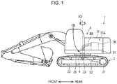
- a swivel joint for a construction machine will be described with reference to Figs. 1 to 9 .
- a hydraulic excavator 1 (see Fig. 1 ) serving as an exemplary construction machine
- a swivel joint 4 (see Fig. 2 ) serving as an exemplary swivel joint will be described.
- the hydraulic excavator 1 includes a lower traveling body 2, an upper slewing body 3 slewably mounted on the lower traveling body 2, and a slewing section 1S incorporating a slewing bearing 25.
- the lower traveling body 2 includes a hydraulic traveling motor 21, a pair of left and right crawlers 22 rotatably driven by the traveling motor 21, a lower frame 23, and a lower pipe 52 connected to the traveling motor 21.
- the slewing section 1S connects the lower traveling body 2 and the upper slewing body 3 with each other in such a manner that the upper slewing body 3 is slewable about a slewing axis AX (slewing central axis) extending in a vertical direction.
- AX slewing central axis
- the upper slewing body 3 has an upper frame 31, a machine chamber 37A, a machine chamber cover 37, and an upper pipe 50.
- the upper frame 31 is supported by the lower traveling body 2 via the slewing bearing 25, and forms a base of the upper slewing body 3.
- the upper frame 31 is configured to be slewable about the slewing axis AX.
- the machine chamber 37A accommodates an unillustrated engine and hydraulic devices (e.g., a control valve 36 and a hydraulic pump).
- the machine chamber cover 37 is provided to cover the machine chamber 37A.
- the slewing section 1S includes the swivel joint 4 provided at the center of the slewing bearing 25.
- the swivel joint 4 is a member having a vertically long and substantially cylindrical shape to stand in a central portion of the lower frame 23 with a center of the swivel joint 4 being on the slewing axis X.
- the swivel joint 4 connects the upper pipe 50 leading to the control valve 36 of the upper slewing body 3 and the lower pipe 52 leading to the traveling motor 21 of the lower traveling body 2 with each other therebetween.
- the swivel joint 4 includes a body 41, a stem 43 rotatably fitted in the body 41, a cover 45 (lower cover), and a cover 47 (auxiliary cover).
- the cover 45 and the cover 47 constitute a cover unit 44.
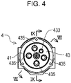
- the body 41 is a member fixedly attachable to the lower frame 23 of the lower traveling body 2 and having a hollow cylindrical shape centered on the slewing axis AX, the body being referred to as a lower swivel as well.
- the body 41 opens at an upper end and a lower end respectively, that is, has an upper opening and a lower opening.
- the stem 43 is a member fixedly attachable to the upper frame 31 of the upper slewing body 3 and having a cylindrical shape centered on the slewing axis AX, the stem being referred to as an upper swivel as well.
- the stem 43 is fitted in a cylindrical inner part of the body 41 through the upper opening of the body 41 rotatably about the slewing axis AX relative to the body 41.
- the stem 43 has a lower surface portion facing the cover 45.
- the stem 43 further has a thrust plate 432 at the lower end of the stem 43.
- the thrust plate 432 is a member for preventing the stem 43 from leaving out of the body 41 in a slewing axial direction.
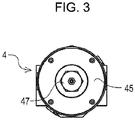
- the cover 45 is fastened to a lower portion of the body 41 with bolts.
- the cover 45 is mounted to the body 41 to close the lower opening of the body 41.
- the cover 45 has an attachment hole 45H vertically extending through the cover 45 along the central axis (slewing axis AX) of the stem 43 for receiving the cover 47 (which will be described later) to be attached therein.
- the cover 45 has a doughnut shape.
- the cover 45 serves as an exemplary first cover according to the present invention.
- the cover 47 is attached to the cover 45 via the attachment hole 45H.
- the attachment hole 45H of the cover 45 is defined by a female thread, and a fastening part 47S (see FIG. 7 ) of the cover 47 is formed with a male thread, and the cover 47 is screwed in the attachment hole 45H of the cover 45.
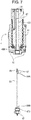
- the cover 45 is fixedly mounted to the body 41 as described above, and thus the mounting state of the cover 45 to the body 41 is maintained even when the cover 47 is detached from the cover 45 (see FIG. 7 )
- the swivel joint 4 further includes a sensor unit 5 for detecting a slewing angle of the upper slewing body 3 with respect to the lower traveling body 2.
- the sensor unit 5 includes a rotation angle sensor 51 and a rod 53.
- the rotation angle sensor 51 is fixedly attached to the upper end of the stem 43 and rotates together with the stem 43 while following the slewing of the upper slewing body 3. That is to say, the rotation angle sensor 51 is placed in a sensor placement space 430 of the stem 43 in such a manner as to be rotatable integrally with the stem 43 about the slewing axis AX.
- the rod 53 is a member having a rod shape and provided with a magnet 55 to be detected by the rotation angle sensor 51 on a tip thereof.
- the rod 53 has a rod distal end 53A and a rod proximal end 53B, and extends in the vertical direction (axial direction of the slewing axis AX).
- the rod distal end 53A of the rod 53 has a tip surface portion formed with an unillustrated countersink (recess) for receiving the magnet 55 (detection target) to be fitted therein to face the rotation angle sensor 51.
- the countersink has such a size, i.e., 0.5 millimeter (mm) or less here, as not to affect a magnetic field density of the magnet 55.
- the magnet 55 is arranged in the countersink in the tip surface portion of the rod 53, and is directly adhered to the rod distal end 53A with an adhesive.
- the rod distal end 53A is provided with the magnet 55 to be detected by the rotation angle sensor 51.
- the rod proximal end 53B of the rod 53 is directly and separably fastened to the cover 47 in a threaded engagement.
- the cover 47 consequently holds the rod proximal end 53B after the rod proximal end 53B is fastened to the cover 47.
- the rod 53 is rotatable with the body 41 about the slewing axis AX relative to the stem 43.
- the cover 47 is fastened to the cover 45, and the cover 45 is fixedly mounted to the body 41. Particularly, the cover 47 is detachably attached to the cover 45 in such a manner as to close the attachment hole 45H of the cover 45.
- the body 41 is fixedly attached to the lower traveling body 2. Therefore, unlike the rotation angle sensor 51, the rod 53 fastened to the cover 47 and the magnet 55 provided on the tip of the rod 53 avoid following the slewing of the upper slewing body 3.
- the rod proximal end 53B is detachably attached in the attachment hole 45H of the cover 45 so that the rod distal end 53A is inserted through the rod hole 431 from the attachment hole 45H of the cover 45 to a position where the magnet 55 is detected by the rotation angle sensor 51 and that the rod distal end 53A is withdrawn below the attachment hole 45H from the rod hole 431 in the state where the cover 45 is mounted to the body 41.
- the rotation angle sensor 51 and the magnet 55 are preferably concentric with each other to accurately detect the slewing angle of the upper slewing body. Therefore, in this embodiment, the distal end of the rod 53 is provided with a collar 57 (restrictive member).
- the collar 57 is a member for suppressing a run-out of the rod 53 and is made of a nonmagnetic resin material. Specifically, the collar 57 is located on the rod distal end 53A and has an outer diameter larger than an outer diameter of the rod 53. The collar 57 restricts a relative position of the magnet 55 to the rotation angle sensor 51 in a direction perpendicularly intersecting the axial direction of the slewing axis AX.
- the attachment hole 45H for receiving the cover 47 to be attached therein is configured to have an inner diameter larger than the outer diameter of the collar 57. This aims at allowing the rod 53 provided with the collar 57 to be inserted through and withdrawn from the rod hole 431.
- the stem 43 is formed with the sensor placement space 430, the rod hole 431 (rod insertion space) axially extending along the central axis of the stem 43, a drain hole 433 (stem-side drain oil passage) axially extending at a position deviating from the central axis of the stem 43, and four vertical holes 435 axially extending at corresponding positions deviating from the central axis of the stem 43.
- the sensor placement space 430 is in the upper end of the stem 43 and overlaps the slewing axis AX.
- the rod hole 431 communicates the sensor placement space 430 and the lower surface portion of the stem 43 with each other, and extends along the slewing axis AX to face the attachment hole 45H.
- the drain hole 433 is spaced radially outward from the rod hole 431 in the stem 43 and communicating with the upper pipe 50 for permitting a drain oil to flow in the vertical direction.
- the rod hole 431 is a dedicated hole for allowing the rod 53 to be inserted therethrough and withdrawn therefrom without allowing the oil to pass therethrough.
- the rod 53 fastened to the cover 47 is inserted through the rod hole 431 from the attachment hole 45H when the cover 47 is attached to the cover 45.
- the magnet 55 on the tip of the rod 53 accordingly approaches the rotation angle sensor 51.
- the drain hole 433 allows the drain oil to pass therethrough and communicates with a drain oil passage 451 (cover-side drain oil passage, i.e., hatched area in FIG. 9 ) formed in the cover 45.
- the drain oil passage 451 is isolated from the rod hole 431 and the attachment hole 45H for communicating the drain hole 433 of the stem 43 and the lower pipe 52 with each other in the state where the cover 45 is mounted to the body 41.
- the drain oil passage 451 includes an oil chamber 451A having a doughnut shape and provided along an outer circumference of the stem 43, and an L-oil passage 451B having an L-shape for connecting the oil chamber 451A and a side surface portion of the cover 45 with each other.
- the drain hole 433 communicates with the oil chamber 451A of the drain oil passage 451.
- a contact portion between the stem 43 and the cover 45 is provided with a sealant 6 for preventing a leakage of the drain oil.
- the sealant 6 is an elastic member having a link shape, and is disposed between the stem 43 and the cover 45 for keeping the oil from flowing into the rod hole 431 and the attachment hole 45H from the drain oil passage 451. This is because the drain oil may ooze out of the contact portion between the stem 43 and the cover 45 and an oil leakage may occur in relation to the presence of the drain oil passage 451 in the cover 45.
- the stem 43 has a small diameter part incorporating the slewing axis AX at the lower end thereof, and a large diameter part extending upward from the small diameter part.
- the lower surface portion of the stem 43 corresponds to a lower surface portion of the small diameter part.
- the rod hole 431 communicates with the lower surface portion of the small diameter part.
- the cover 45 has a cylindrical inner part for receiving the small diameter part 43 of the stem 43 therein, and an upper surface portion to be in contact with the lower surface portion of the large diameter part of the stem ( FIG. 6 ).
- the cover 47 is fitted in the lower portion of the cylindrical inner part of the cover 45 from below.
- the sealant 6 is disposed between an inner circumference of the cover 45 and an outer circumference of the small diameter part of the stem 43 to suppress an inflow of the drain oil from the drain oil passage 451 into the rod hole 431.
- Each of the four vertical holes 435 serves as an oil passage for supplying and discharging the hydraulic oil between the control valve 36 and the traveling motor 21.
- Fig. 9 one of the four vertical holes 435 is shown.
- the vertical hole 435 has a configuration similar to that of a prior art (e.g., Patent Literature 1).
- the rod 53 is inserted through the rod hole 431 which keeps the oil from passing therethrough.
- This configuration eliminates the possibility of the oil leakage even at the insertion and withdrawal of the rod 53 for a maintenance operation.
- the drain hole 433 is independent of the rod hole 431 and communicates with the drain oil passage 451 of the cover 45 fixedly mounted to the body 41. Hence, the cover 45 remains fixedly mounted to the body 41 even when the cover 45 is detached from the cover 47. In this manner, the drain hole 433 is kept closed. This eliminates the possibility of the oil leakage from the drain hole 433. Consequently, the swivel joint 4 according to the embodiment can facilitate replacement of the rod 53, and has a high maintainability of the sensor unit 5 including the rod 53.
- the rotation angle sensor 51 and the magnet 55 avoid coming into contact with the hydraulic oil. Accordingly, these components need no oil resistance.
- the above-described embodiment can additionally adopt an angle detection function without a significant change in the layout of the hydraulic excavator 1. Besides, the attachability and detachability of the swivel joint can compete against those of a typical swivel joint.
- the rod 53 fastened to the cover 47 can be taken out by detaching the cover 47 from the cover 45.
- the magnet 55 is replaceable without detaching the body 41 or the stem 43 of the swivel joint 4 from a main body of the excavator.
- the collar 57 is located on the distal end of the rod 53. This prevents the run-out of the rod 53, and keeps the magnet 55 staying in a sensing area of the rotation angle sensor 51 without deviating therefrom. Also, the collar 57 made of a nonmagnetic resin material prevents the inner circumference defining the rod hole 431 of the stem 43 from being worn out.
- the magnet 55 is directly arranged in the countersink (recess) at the distal end of the rod 53 through adhesion with the adhesive. This eliminates the necessity of adding another nonmagnetic member between the magnet 55 and the rod 53 serving as a magnetic member, thereby achieving a decrease in the number of components.
- the swivel joint for a construction machine according to the present invention is not limited to the above-described embodiment, and various modifications and improvements are applicable within the scope of the claims.
- the cover 45 is fixedly mounted to the body 41, and the cover 47 including the rod 53 is configured to be attachable to and detachable from the cover 45 as shown in FIG. 7 , but the configuration should not be limited thereto.
- the swivel joint may be configured to include a cover fixedly mounted to a body 41 and a rod which can be directly fastened to the cover.
- the swivel joint may be configured to include a single cover and a rod which can be fastened to the cover.
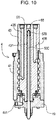
- a cover 49 having a drain oil passage 491 is fixedly mounted to a body 41 as shown in Fig. 10 .
- a rod 530 has a rod proximal end configured to be fastened to the cover 49 in a threaded engagement.
- the rod proximal end of the rod 530 to be fastened to the cover 49 has a diameter larger than a diameter of a collar 570.
- the modified embodiment can decrease the number of components constituting the swivel joint 4. This consequently succeeds in an assembly tolerance reduction and suppression of the run-out of the rod 530 from the swivel joint 4 (specifically, the rod hole 431 of the stem 43).
- the configuration according to the present invention is suitable for use in a swivel joint or the like for a hydraulic excavator, which includes a sensor unit for detecting a slewing angle of an upper slewing body.
- a swivel joint for a construction machine which includes a lower traveling body having a lower pipe, an upper slewing body having an upper pipe, and a slewing section for connecting the lower traveling body and the upper slewing body with each other in such a manner that the upper slewing body is slewable about a slewing central axis extending in a vertical direction, the swivel joint being provided in the slewing section.
- the swivel joint includes: a body fixedly attachable to the lower traveling body, having a hollow cylindrical shape centered on the slewing central axis, and having an upper opening and a lower opening; a lower cover mounted to the body to close the lower opening of the body, and having an attachment hole vertically extending through the lower cover along the slewing central axis; a stem fixedly attachable to the upper slewing body, having a cylindrical shape centered on the slewing central axis, and fitted in a cylindrical inner part of the body through the upper opening of the body rotatably about the slewing central axis relative to the body; and a sensor unit for detecting a slewing angle of the upper slewing body with respect to the lower traveling body.
- the stem has a lower surface portion facing the lower cover, and is formed with: a sensor placement space overlapping the slewing central axis; a rod insertion hole extending along the slewing central axis and communicating the sensor placement space and the lower surface portion with each other to face the attachment hole; and a stem-side drain oil passage spaced radially outward from the rod insertion hole therein and communicating with the upper pipe for permitting a drain oil to flow in the vertical direction.
- the lower cover has a cover-side drain oil passage isolated from the rod insertion hole and the attachment hole for communicating the stem-side drain oil passage of the stem and the lower pipe with each other in a state where the lower cover is mounted to the body.
- the sensor unit includes: a rotation angle sensor placed in the sensor placement space of the stem in such a manner as to be rotatable integrally with the stem about the slewing central axis; and a rod extending in the vertical direction.
- the rod has a rod distal end provided with a detection target to be detected by the rotation angle sensor, and a rod proximal end which is detachably attached in the attachment hole of the lower cover so that the rod distal end is inserted through the rod insertion hole from the attachment hole of the lower cover to a position where the detection target is detected by the rotation angle sensor and that the rod distal end is withdrawn below the attachment hole from the rod insertion hole in the state where the lower cover is mounted to the body.
- the rod is rotatable with the body relative to the stem about the slewing central axis.
- the rod is inserted into the rod insertion hole spaced from the stem-side drain oil passage.
- an oil leakage from the rod insertion hole is suppressed even at the insertion and withdrawal of the rod.
- the swivel joint for a construction machine according to the present invention can facilitate replacement of the rod provided with the detection target, and has a high maintainability.
- This configuration preferably further includes an auxiliary cover holding the rod proximal end and detachably attached to the lower cover in such a manner as to close the attachment hole of the lower cover.
- the stem-side oil passage is spaced from the rod insertion hole and communicates with the cover-side drain oil passage of the lower cover fixedly mounted to the body.
- the stem-side drain oil passage is kept closed even when the auxiliary cover is detached from the lower cover. This configuration suppresses the oil leakage from the stem-side drain oil passage.
- auxiliary cover and the rod proximal end are separably fastened to each other in a threaded engagement.
- the sensor unit preferably further includes: a restrictive member located on the rod distal end and having an outer diameter larger than an outer diameter of the rod for restricting a relative position of the detection target to the rotation angle sensor in a direction perpendicularly intersecting an axial direction of the slewing central axis, and the attachment hole preferably has an inner diameter larger than the outer diameter of the restrictive member.
- the restrictive member is desirably made of a nonmagnetic resin material.
- the rod distal end has a recess facing the rotation angle sensor, and that the detection target includes a magnet arranged in the recess and adhered to the rod distal end.
- This configuration desirably further includes: a sealant disposed between the stem and the lower cover for keeping an oil from flowing into the insertion space and the attachment hole from the cover-side oil passage.
Landscapes
- Engineering & Computer Science (AREA)
- General Engineering & Computer Science (AREA)
- Mining & Mineral Resources (AREA)
- Civil Engineering (AREA)
- Structural Engineering (AREA)
- Mechanical Engineering (AREA)
- Component Parts Of Construction Machinery (AREA)
- Joints Allowing Movement (AREA)
- Pivots And Pivotal Connections (AREA)
- Length Measuring Devices With Unspecified Measuring Means (AREA)
Abstract
Description
- The present invention relates to a swivel joint to be provided at a slewing center of a construction machine, such as a hydraulic excavator.
- Technologies concerning a swivel joint to be provided in a slewing section for connecting a lower traveling body and an upper slewing body with each other have been conventionally proposed in the field of construction machines.
- For instance, Patent Literature 1 discloses a swivel joint for connecting an upper pipe and a lower pipe with each other at a center of a slewing bearing.
- Specifically, the swivel joint includes a hollow cylindrical body to be fixedly attached to a lower frame of the lower traveling body, and a cylindrical stem to be fixedly attached to an upper frame of the upper slewing body and rotatably fitted in the body. The stem is formed with a drain hole axially extending therethrough at a center of an upper surface thereof.
-
Patent Literature 2 discloses, as another technology, a swivel joint including a rotation angle sensor for detecting a slewing angle of the upper slewing body, and a rod. - Specifically, the rod is inserted through an axially extending pilot oil passage to detect the slewing angle of the upper slewing body. The rod has an upper end spaced from the rotation angle sensor attached to an inner body to face the sensor.
-
- Patent Literature 1:
Japanese Unexamined Patent Publication No. 2016-3519 - Patent Literature 2:
Japanese Unexamined Patent Publication No. 2017-82494 - It is conceived from
Patent Literatures 1 and 2 to provide a sensor unit (including a rotation angle sensor and a rod) for detecting a slewing angle of an upper slewing body by using an oil passage and a drain hole defined at a slewing center of the stem. - However, such a configuration of inserting a rod into an oil passage and a drain hole defined at a slewing center of the stem has a possibility of a leakage of a hydraulic oil from the oil passage in operations of inserting and withdrawing the rod thereinto and therefrom, and thus faces a maintainability problem.
- An object of the present invention is to provide a swivel joint for a construction machine, which includes a sensor unit for detecting a slewing angle of an upper slewing body and suppresses an oil leakage at insertion and withdrawal of the rod.
- Provided by the present invention is a swivel joint for a construction machine which includes a lower traveling body having a lower pipe, an upper slewing body having an upper pipe, and a slewing section for connecting the lower traveling body and the upper slewing body with each other in such a manner that the upper slewing body is slewable about a slewing central axis extending in a vertical direction, the swivel joint being provided in the slewing section. The swivel joint includes: a body fixedly attachable to the lower traveling body, having a hollow cylindrical shape centered on the slewing central axis, and having an upper opening and a lower opening; a lower cover mounted to the body to close the lower opening of the body, and having an attachment hole vertically extending through the lower cover along the slewing central axis; a stem fixedly attachable to the upper slewing body, having a cylindrical shape centered on the slewing central axis, and fitted in a cylindrical inner part of the body through the upper opening of the body rotatably about the slewing central axis relative to the body; and a sensor unit for detecting a slewing angle of the upper slewing body with respect to the lower traveling body. The stem has a lower surface portion facing the lower cover, and is formed with: a sensor placement space overlapping the slewing central axis; a rod insertion hole extending along the slewing central axis and communicating the sensor placement space and the lower surface portion with each other to face the attachment hole; and a stem-side drain oil passage spaced radially outward from the rod insertion hole in the stem and communicating with the upper pipe for permitting a drain oil to flow in the vertical direction. The lower cover has a cover-side drain oil passage isolated from the rod insertion hole and the attachment hole for communicating the stem-side drain oil passage of the stem and the lower pipe with each other in a state where the lower cover is mounted to the body. The sensor unit includes: a rotation angle sensor placed in the sensor placement space of the stem in such a manner as to be rotatable integrally with the stem about the slewing central axis; and a rod extending in the vertical direction. The rod has a rod distal end provided with a detection target to be detected by the rotation angle sensor, and a rod proximal end which is detachably attached in the attachment hole of the lower cover so that the rod distal end is inserted through the rod insertion hole from the attachment hole of the lower cover to a position where the detection target is detected by the rotation angle sensor and that the rod distal end is withdrawn below the attachment hole from the rod insertion hole in the state where the lower cover is mounted to the body. The rod is rotatable with the body about the slewing central axis relative to the stem.
-
-
Fig. 1 is a sideview of a hydraulic excavator according to an embodiment of the present invention. -
Fig. 2 is a sideview of an appearance of a swivel joint according to the embodiment of the present invention. -
Fig. 3 is a bottom view of the swivel joint inFig. 2 seen along the arrow III. -
Fig. 4 is a plan view of the swivel joint inFig. 2 seen along the arrow IV. -
Fig. 5 is a cross-sectional view of the swivel joint inFig. 2 taken along the line V-V. -
Fig. 6 is a cross-sectional view of the swivel joint inFig. 2 taken along the line VI-VI. -
Fig. 7 is a cross-sectional view showing a state where a rod is removed from the swivel joint inFig. 6 . -
Fig. 8 is a cross-sectional view of the swivel joint inFig. 4 taken along the line VIII-VIII. -
Fig. 9 is a cross-sectional view of the swivel joint inFig. 4 taken along the line IX-IX. -
Fig. 10 is a sideview of a swivel joint according to a modified embodiment of the present invention. - A swivel joint for a construction machine according to an embodiment of the present invention will be described with reference to
Figs. 1 to 9 . Hereinafter, a hydraulic excavator 1 (seeFig. 1 ) serving as an exemplary construction machine and a swivel joint 4 (seeFig. 2 ) serving as an exemplary swivel joint will be described. - As shown in
Fig. 1 , the hydraulic excavator 1 includes alower traveling body 2, an upper slewing body 3 slewably mounted on the lower travelingbody 2, and aslewing section 1S incorporating a slewing bearing 25. Thelower traveling body 2 includes ahydraulic traveling motor 21, a pair of left andright crawlers 22 rotatably driven by the travelingmotor 21, alower frame 23, and alower pipe 52 connected to thetraveling motor 21. Theslewing section 1S connects the lowertraveling body 2 and the upper slewing body 3 with each other in such a manner that the upper slewing body 3 is slewable about a slewing axis AX (slewing central axis) extending in a vertical direction. - The upper slewing body 3 has an
upper frame 31, amachine chamber 37A, amachine chamber cover 37, and anupper pipe 50. Theupper frame 31 is supported by the lower travelingbody 2 via the slewing bearing 25, and forms a base of the upper slewing body 3. Theupper frame 31 is configured to be slewable about the slewing axis AX. - The
machine chamber 37A accommodates an unillustrated engine and hydraulic devices (e.g., acontrol valve 36 and a hydraulic pump). Themachine chamber cover 37 is provided to cover themachine chamber 37A. - The
slewing section 1S includes theswivel joint 4 provided at the center of the slewing bearing 25. Theswivel joint 4 is a member having a vertically long and substantially cylindrical shape to stand in a central portion of thelower frame 23 with a center of theswivel joint 4 being on the slewing axis X. Theswivel joint 4 connects theupper pipe 50 leading to thecontrol valve 36 of the upper slewing body 3 and thelower pipe 52 leading to the travelingmotor 21 of thelower traveling body 2 with each other therebetween. - As shown in
Fig. 2 , theswivel joint 4 includes abody 41, astem 43 rotatably fitted in thebody 41, a cover 45 (lower cover), and a cover 47 (auxiliary cover). Thecover 45 and thecover 47 constitute acover unit 44. - As shown in
Figs. 2 and4 , thebody 41 is a member fixedly attachable to thelower frame 23 of the lower travelingbody 2 and having a hollow cylindrical shape centered on the slewing axis AX, the body being referred to as a lower swivel as well. Thebody 41 opens at an upper end and a lower end respectively, that is, has an upper opening and a lower opening. - As shown in
Figs. 2 ,4 , and5 , thestem 43 is a member fixedly attachable to theupper frame 31 of the upper slewing body 3 and having a cylindrical shape centered on the slewing axis AX, the stem being referred to as an upper swivel as well. Thestem 43 is fitted in a cylindrical inner part of thebody 41 through the upper opening of thebody 41 rotatably about the slewing axis AX relative to thebody 41. Thestem 43 has a lower surface portion facing thecover 45. - As shown in
Fig. 6 , thestem 43 further has athrust plate 432 at the lower end of thestem 43. Thethrust plate 432 is a member for preventing thestem 43 from leaving out of thebody 41 in a slewing axial direction. - As shown in
Figs. 3 and8 , thecover 45 is fastened to a lower portion of thebody 41 with bolts. Thecover 45 is mounted to thebody 41 to close the lower opening of thebody 41. As shown inFig. 6 , thecover 45 has anattachment hole 45H vertically extending through thecover 45 along the central axis (slewing axis AX) of thestem 43 for receiving the cover 47 (which will be described later) to be attached therein. In other words, thecover 45 has a doughnut shape. Thecover 45 serves as an exemplary first cover according to the present invention. - As shown in
Figs. 3 and6 , thecover 47 is attached to thecover 45 via theattachment hole 45H. Specifically, theattachment hole 45H of thecover 45 is defined by a female thread, and afastening part 47S (seeFIG. 7 ) of thecover 47 is formed with a male thread, and thecover 47 is screwed in theattachment hole 45H of thecover 45. - Here, the
cover 45 is fixedly mounted to thebody 41 as described above, and thus the mounting state of thecover 45 to thebody 41 is maintained even when thecover 47 is detached from the cover 45 (seeFIG. 7 ) - As shown in
Fig. 6 , the swivel joint 4 further includes a sensor unit 5 for detecting a slewing angle of the upper slewing body 3 with respect to thelower traveling body 2. The sensor unit 5 includes arotation angle sensor 51 and arod 53. - The
rotation angle sensor 51 is fixedly attached to the upper end of thestem 43 and rotates together with thestem 43 while following the slewing of the upper slewing body 3. That is to say, therotation angle sensor 51 is placed in asensor placement space 430 of thestem 43 in such a manner as to be rotatable integrally with thestem 43 about the slewing axis AX. - The
rod 53 is a member having a rod shape and provided with amagnet 55 to be detected by therotation angle sensor 51 on a tip thereof. Therod 53 has a roddistal end 53A and a rodproximal end 53B, and extends in the vertical direction (axial direction of the slewing axis AX). - The rod
distal end 53A of therod 53 has a tip surface portion formed with an unillustrated countersink (recess) for receiving the magnet 55 (detection target) to be fitted therein to face therotation angle sensor 51. The countersink has such a size, i.e., 0.5 millimeter (mm) or less here, as not to affect a magnetic field density of themagnet 55. - The
magnet 55 is arranged in the countersink in the tip surface portion of therod 53, and is directly adhered to the roddistal end 53A with an adhesive. As a result, the roddistal end 53A is provided with themagnet 55 to be detected by therotation angle sensor 51. The rodproximal end 53B of therod 53 is directly and separably fastened to thecover 47 in a threaded engagement. Thecover 47 consequently holds the rodproximal end 53B after the rodproximal end 53B is fastened to thecover 47. Moreover, therod 53 is rotatable with thebody 41 about the slewing axis AX relative to thestem 43. - The
cover 47 is fastened to thecover 45, and thecover 45 is fixedly mounted to thebody 41. Particularly, thecover 47 is detachably attached to thecover 45 in such a manner as to close theattachment hole 45H of thecover 45. Thebody 41 is fixedly attached to thelower traveling body 2. Therefore, unlike therotation angle sensor 51, therod 53 fastened to thecover 47 and themagnet 55 provided on the tip of therod 53 avoid following the slewing of the upper slewing body 3. As an additional remark for the rodproximal end 53B, the rodproximal end 53B is detachably attached in theattachment hole 45H of thecover 45 so that the roddistal end 53A is inserted through therod hole 431 from theattachment hole 45H of thecover 45 to a position where themagnet 55 is detected by therotation angle sensor 51 and that the roddistal end 53A is withdrawn below theattachment hole 45H from therod hole 431 in the state where thecover 45 is mounted to thebody 41. - The
rotation angle sensor 51 and themagnet 55 are preferably concentric with each other to accurately detect the slewing angle of the upper slewing body. Therefore, in this embodiment, the distal end of therod 53 is provided with a collar 57 (restrictive member). Thecollar 57 is a member for suppressing a run-out of therod 53 and is made of a nonmagnetic resin material. Specifically, thecollar 57 is located on the roddistal end 53A and has an outer diameter larger than an outer diameter of therod 53. Thecollar 57 restricts a relative position of themagnet 55 to therotation angle sensor 51 in a direction perpendicularly intersecting the axial direction of the slewing axis AX. - As shown in
Fig. 7 , theattachment hole 45H for receiving thecover 47 to be attached therein is configured to have an inner diameter larger than the outer diameter of thecollar 57. This aims at allowing therod 53 provided with thecollar 57 to be inserted through and withdrawn from therod hole 431. - As shown in
Fig. 5 , thestem 43 is formed with thesensor placement space 430, the rod hole 431 (rod insertion space) axially extending along the central axis of thestem 43, a drain hole 433 (stem-side drain oil passage) axially extending at a position deviating from the central axis of thestem 43, and fourvertical holes 435 axially extending at corresponding positions deviating from the central axis of thestem 43. Thesensor placement space 430 is in the upper end of thestem 43 and overlaps the slewing axis AX. Therod hole 431 communicates thesensor placement space 430 and the lower surface portion of thestem 43 with each other, and extends along the slewing axis AX to face theattachment hole 45H. Thedrain hole 433 is spaced radially outward from therod hole 431 in thestem 43 and communicating with theupper pipe 50 for permitting a drain oil to flow in the vertical direction. - As shown in
Fig. 7 , therod hole 431 is a dedicated hole for allowing therod 53 to be inserted therethrough and withdrawn therefrom without allowing the oil to pass therethrough. As shown inFig. 6 , therod 53 fastened to thecover 47 is inserted through therod hole 431 from theattachment hole 45H when thecover 47 is attached to thecover 45. Themagnet 55 on the tip of therod 53 accordingly approaches therotation angle sensor 51. - As shown in
Fig. 8 , thedrain hole 433 allows the drain oil to pass therethrough and communicates with a drain oil passage 451 (cover-side drain oil passage, i.e., hatched area inFIG. 9 ) formed in thecover 45. Thedrain oil passage 451 is isolated from therod hole 431 and theattachment hole 45H for communicating thedrain hole 433 of thestem 43 and thelower pipe 52 with each other in the state where thecover 45 is mounted to thebody 41. - As shown in
Fig. 9 , thedrain oil passage 451 includes anoil chamber 451A having a doughnut shape and provided along an outer circumference of thestem 43, and an L-oil passage 451B having an L-shape for connecting theoil chamber 451A and a side surface portion of thecover 45 with each other. As shown inFig. 8 , thedrain hole 433 communicates with theoil chamber 451A of thedrain oil passage 451. - As shown in
FIG. 9 , a contact portion between thestem 43 and thecover 45 is provided with asealant 6 for preventing a leakage of the drain oil. Thesealant 6 is an elastic member having a link shape, and is disposed between thestem 43 and thecover 45 for keeping the oil from flowing into therod hole 431 and theattachment hole 45H from thedrain oil passage 451. This is because the drain oil may ooze out of the contact portion between thestem 43 and thecover 45 and an oil leakage may occur in relation to the presence of thedrain oil passage 451 in thecover 45. - The
stem 43 has a small diameter part incorporating the slewing axis AX at the lower end thereof, and a large diameter part extending upward from the small diameter part. The lower surface portion of thestem 43 corresponds to a lower surface portion of the small diameter part. Therod hole 431 communicates with the lower surface portion of the small diameter part. In contrast, thecover 45 has a cylindrical inner part for receiving thesmall diameter part 43 of thestem 43 therein, and an upper surface portion to be in contact with the lower surface portion of the large diameter part of the stem (FIG. 6 ). Thecover 47 is fitted in the lower portion of the cylindrical inner part of thecover 45 from below. Thesealant 6 is disposed between an inner circumference of thecover 45 and an outer circumference of the small diameter part of thestem 43 to suppress an inflow of the drain oil from thedrain oil passage 451 into therod hole 431. - Each of the four
vertical holes 435 serves as an oil passage for supplying and discharging the hydraulic oil between thecontrol valve 36 and the travelingmotor 21. InFig. 9 , one of the fourvertical holes 435 is shown. Thevertical hole 435 has a configuration similar to that of a prior art (e.g., Patent Literature 1). - According to the above-described embodiment, the
rod 53 is inserted through therod hole 431 which keeps the oil from passing therethrough. This configuration eliminates the possibility of the oil leakage even at the insertion and withdrawal of therod 53 for a maintenance operation. Furthermore, thedrain hole 433 is independent of therod hole 431 and communicates with thedrain oil passage 451 of thecover 45 fixedly mounted to thebody 41. Hence, thecover 45 remains fixedly mounted to thebody 41 even when thecover 45 is detached from thecover 47. In this manner, thedrain hole 433 is kept closed. This eliminates the possibility of the oil leakage from thedrain hole 433. Consequently, the swivel joint 4 according to the embodiment can facilitate replacement of therod 53, and has a high maintainability of the sensor unit 5 including therod 53. - Moreover, according to the above-described embodiment, the
rotation angle sensor 51 and themagnet 55 avoid coming into contact with the hydraulic oil. Accordingly, these components need no oil resistance. - The above-described embodiment can additionally adopt an angle detection function without a significant change in the layout of the hydraulic excavator 1. Besides, the attachability and detachability of the swivel joint can compete against those of a typical swivel joint.
- Furthermore, according to the above-described embodiment, the
rod 53 fastened to thecover 47 can be taken out by detaching thecover 47 from thecover 45. In this way, themagnet 55 is replaceable without detaching thebody 41 or thestem 43 of the swivel joint 4 from a main body of the excavator. - Further, according to the above-described embodiment, the
collar 57 is located on the distal end of therod 53. This prevents the run-out of therod 53, and keeps themagnet 55 staying in a sensing area of therotation angle sensor 51 without deviating therefrom. Also, thecollar 57 made of a nonmagnetic resin material prevents the inner circumference defining therod hole 431 of thestem 43 from being worn out. - According to the above-described embodiment, the
magnet 55 is directly arranged in the countersink (recess) at the distal end of therod 53 through adhesion with the adhesive. This eliminates the necessity of adding another nonmagnetic member between themagnet 55 and therod 53 serving as a magnetic member, thereby achieving a decrease in the number of components. - The swivel joint for a construction machine according to the present invention is not limited to the above-described embodiment, and various modifications and improvements are applicable within the scope of the claims.
- In the above-described embodiment, for example, the
cover 45 is fixedly mounted to thebody 41, and thecover 47 including therod 53 is configured to be attachable to and detachable from thecover 45 as shown inFIG. 7 , but the configuration should not be limited thereto. For instance, the swivel joint may be configured to include a cover fixedly mounted to abody 41 and a rod which can be directly fastened to the cover. In other words, the swivel joint may be configured to include a single cover and a rod which can be fastened to the cover. - Specifically, in a swivel joint according to a modified embodiment of the present invention, a
cover 49 having adrain oil passage 491 is fixedly mounted to abody 41 as shown inFig. 10 . Further, arod 530 has a rod proximal end configured to be fastened to thecover 49 in a threaded engagement. The rod proximal end of therod 530 to be fastened to thecover 49 has a diameter larger than a diameter of acollar 570. - The modified embodiment can decrease the number of components constituting the
swivel joint 4. This consequently succeeds in an assembly tolerance reduction and suppression of the run-out of therod 530 from the swivel joint 4 (specifically, therod hole 431 of the stem 43). - Conclusively, the configuration according to the present invention is suitable for use in a swivel joint or the like for a hydraulic excavator, which includes a sensor unit for detecting a slewing angle of an upper slewing body.
- Provided by the present invention is a swivel joint for a construction machine which includes a lower traveling body having a lower pipe, an upper slewing body having an upper pipe, and a slewing section for connecting the lower traveling body and the upper slewing body with each other in such a manner that the upper slewing body is slewable about a slewing central axis extending in a vertical direction, the swivel joint being provided in the slewing section. The swivel joint includes: a body fixedly attachable to the lower traveling body, having a hollow cylindrical shape centered on the slewing central axis, and having an upper opening and a lower opening; a lower cover mounted to the body to close the lower opening of the body, and having an attachment hole vertically extending through the lower cover along the slewing central axis; a stem fixedly attachable to the upper slewing body, having a cylindrical shape centered on the slewing central axis, and fitted in a cylindrical inner part of the body through the upper opening of the body rotatably about the slewing central axis relative to the body; and a sensor unit for detecting a slewing angle of the upper slewing body with respect to the lower traveling body. The stem has a lower surface portion facing the lower cover, and is formed with: a sensor placement space overlapping the slewing central axis; a rod insertion hole extending along the slewing central axis and communicating the sensor placement space and the lower surface portion with each other to face the attachment hole; and a stem-side drain oil passage spaced radially outward from the rod insertion hole therein and communicating with the upper pipe for permitting a drain oil to flow in the vertical direction. The lower cover has a cover-side drain oil passage isolated from the rod insertion hole and the attachment hole for communicating the stem-side drain oil passage of the stem and the lower pipe with each other in a state where the lower cover is mounted to the body. The sensor unit includes: a rotation angle sensor placed in the sensor placement space of the stem in such a manner as to be rotatable integrally with the stem about the slewing central axis; and a rod extending in the vertical direction. The rod has a rod distal end provided with a detection target to be detected by the rotation angle sensor, and a rod proximal end which is detachably attached in the attachment hole of the lower cover so that the rod distal end is inserted through the rod insertion hole from the attachment hole of the lower cover to a position where the detection target is detected by the rotation angle sensor and that the rod distal end is withdrawn below the attachment hole from the rod insertion hole in the state where the lower cover is mounted to the body. The rod is rotatable with the body relative to the stem about the slewing central axis.
- According to this configuration, the rod is inserted into the rod insertion hole spaced from the stem-side drain oil passage. Hence, an oil leakage from the rod insertion hole is suppressed even at the insertion and withdrawal of the rod. Accordingly, the swivel joint for a construction machine according to the present invention can facilitate replacement of the rod provided with the detection target, and has a high maintainability.
- This configuration preferably further includes an auxiliary cover holding the rod proximal end and detachably attached to the lower cover in such a manner as to close the attachment hole of the lower cover.
- In this configuration, the stem-side oil passage is spaced from the rod insertion hole and communicates with the cover-side drain oil passage of the lower cover fixedly mounted to the body. Thus, the stem-side drain oil passage is kept closed even when the auxiliary cover is detached from the lower cover. This configuration suppresses the oil leakage from the stem-side drain oil passage.
- In the configuration, it is desired that the auxiliary cover and the rod proximal end are separably fastened to each other in a threaded engagement.
- In the configuration, the sensor unit preferably further includes: a restrictive member located on the rod distal end and having an outer diameter larger than an outer diameter of the rod for restricting a relative position of the detection target to the rotation angle sensor in a direction perpendicularly intersecting an axial direction of the slewing central axis, and the attachment hole preferably has an inner diameter larger than the outer diameter of the restrictive member.
- In this configuration, the restrictive member is desirably made of a nonmagnetic resin material.
- In this configuration, it is desirable that the rod distal end has a recess facing the rotation angle sensor, and that the detection target includes a magnet arranged in the recess and adhered to the rod distal end.
- This configuration desirably further includes: a sealant disposed between the stem and the lower cover for keeping an oil from flowing into the insertion space and the attachment hole from the cover-side oil passage.
Claims (7)
- A swivel joint for a construction machine which includes a lower traveling body having a lower pipe, an upper slewing body having an upper pipe, and a slewing section for connecting the lower traveling body and the upper slewing body with each other in such a manner that the upper slewing body is slewable about a slewing central axis extending in a vertical direction, the swivel joint being provided in the slewing section and comprising:a body fixedly attachable to the lower traveling body, having a hollow cylindrical shape centered on the slewing central axis, and having an upper opening and a lower opening;a lower cover mounted to the body to close the lower opening of the body, and having an attachment hole vertically extending so as to penetrate the lower cover overlapping the slewing central axis;a stem fixedly attachable to the upper slewing body, having a cylindrical shape centered on the slewing central axis, and fitted in a cylindrical inner part of the body through the upper opening of the body rotatably about the slewing central axis relative to the body; anda sensor unit for detecting a slewing angle of the upper slewing body with respect to the lower traveling body, whereinthe stem has a lower surface portion facing the lower cover, and is formed with:a sensor placement space overlapping the slewing central axis;a rod insertion hole extending along the slewing central axis and communicating the sensor placement space and the lower surface portion with each other to face the attachment hole; anda stem-side drain oil passage spaced radially outward from the rod insertion hole in the stem and communicating with the upper pipe for permitting a drain oil to flow in the vertical direction,the lower cover has a cover-side drain oil passage isolated from the rod insertion hole and the attachment hole for communicating the stem-side drain oil passage of the stem and the lower pipe with each other in a state where the lower cover is mounted to the body, andthe sensor unit includes:a rotation angle sensor placed in the sensor placement space of the stem in such a manner as to be rotatable integrally with the stem about the slewing central axis; anda rod extending in the vertical direction, and having a rod distal end provided with a detection target to be detected by the rotation angle sensor, and a rod proximal end which is detachably attached in the attachment hole of the lower cover so that the rod distal end is inserted through the rod insertion hole from the attachment hole of the lower cover to a position where the detection target is detected by the rotation angle sensor and that the rod distal end is withdrawn below the attachment hole from the rod insertion hole in the state where the lower cover is mounted to the body, the rod being rotatable with the body about the slewing central axis relative to the stem.
- The swivel joint for a construction machine according to claim 1, further comprising:
an auxiliary cover holding the rod proximal end and detachably attached to the lower cover in such a manner as to close the attachment hole of the lower cover. - The swivel joint for a construction machine according to claim 2, wherein
the auxiliary cover and the rod proximal end are separably fastened to each other in a threaded engagement. - The swivel joint for a construction machine according to any one of claims 1 to 3, whereinthe sensor unit further includes a restrictive member located on the rod distal end and having an outer diameter larger than an outer diameter of the rod for restricting a relative position of the detection target to the rotation angle sensor in a direction perpendicularly intersecting an axial direction of the slewing central axis, andthe attachment hole has an inner diameter larger than the outer diameter of the restrictive member.
- The swivel joint for a construction machine according to claim 4, wherein
the restrictive member is made of a nonmagnetic resin material. - The swivel joint for a construction machine according to any one of claims 1 to 5, wherein the rod distal end has a recess facing the rotation angle sensor, and
the detection target includes a magnet arranged in the recess and adhered to the rod distal end. - The swivel joint for a construction machine according to any one of claims 1 to 6, further comprising:
a sealant disposed between the stem and the lower cover for keeping an oil from flowing into the rod insertion hole and the attachment hole from the cover-side drain oil passage.
Applications Claiming Priority (2)
| Application Number | Priority Date | Filing Date | Title |
|---|---|---|---|
| JP2019052060A JP7172781B2 (en) | 2019-03-20 | 2019-03-20 | Swivel joint for construction machinery |
| PCT/JP2020/008767 WO2020189246A1 (en) | 2019-03-20 | 2020-03-02 | Swivel joint for construction machine |
Publications (3)
| Publication Number | Publication Date |
|---|---|
| EP3919690A1 true EP3919690A1 (en) | 2021-12-08 |
| EP3919690A4 EP3919690A4 (en) | 2022-04-06 |
| EP3919690B1 EP3919690B1 (en) | 2024-11-06 |
Family
ID=72520961
Family Applications (1)
| Application Number | Title | Priority Date | Filing Date |
|---|---|---|---|
| EP20774000.2A Active EP3919690B1 (en) | 2019-03-20 | 2020-03-02 | Swivel joint for construction machine |
Country Status (5)
| Country | Link |
|---|---|
| US (1) | US20220136208A1 (en) |
| EP (1) | EP3919690B1 (en) |
| JP (1) | JP7172781B2 (en) |
| CN (1) | CN113544335B (en) |
| WO (1) | WO2020189246A1 (en) |
Families Citing this family (10)
| Publication number | Priority date | Publication date | Assignee | Title |
|---|---|---|---|---|
| JP7030504B2 (en) * | 2017-12-22 | 2022-03-07 | 株式会社クボタ | Working machine |
| CN112815906B (en) * | 2020-12-31 | 2022-05-27 | 恒天九五重工有限公司 | Rotary angle detection device of rotary drilling rig |
| JP7624326B2 (en) * | 2021-02-26 | 2025-01-30 | 日立建機株式会社 | Construction Machinery |
| CN114382975A (en) * | 2021-12-11 | 2022-04-22 | 首钢京唐钢铁联合有限责任公司 | Multi-medium rotary joint |
| JP2024040557A (en) * | 2022-09-13 | 2024-03-26 | 株式会社小松製作所 | Power supply unit and swivel joint |
| US12135102B2 (en) * | 2023-02-23 | 2024-11-05 | Axis Forestry Inc. | Swivel connector |
| JP7500910B1 (en) * | 2023-04-14 | 2024-06-18 | 株式会社不二越 | Rotary joint |
| US12612765B2 (en) * | 2023-05-22 | 2026-04-28 | Cnh Industrial America Llc | Hydraulic fitting assembly for a construction vehicle |
| CA3230826A1 (en) * | 2023-08-30 | 2025-06-12 | United Equipment Accessories, Inc. | Pin swivel designs |
| US20250290281A1 (en) * | 2024-03-14 | 2025-09-18 | Doosan Bobcat North America Inc. | Slew rotation sensor |
Family Cites Families (15)
| Publication number | Priority date | Publication date | Assignee | Title |
|---|---|---|---|---|
| NL168770C (en) * | 1976-04-13 | 1982-05-17 | Ihc Holland Nv | SWIVEL COUPLING FOR TWO OR MORE PIPES FOR A TRANSFER BUOY. |
| JPH0426793Y2 (en) * | 1986-10-09 | 1992-06-26 | ||
| JPH06147815A (en) * | 1992-09-18 | 1994-05-27 | Nippondenso Co Ltd | Rotational angle sensor for internal-combustion engine |
| JPH07138995A (en) * | 1993-11-16 | 1995-05-30 | Hitachi Constr Mach Co Ltd | Swivel joint device |
| NO308786B1 (en) * | 1995-06-22 | 2000-10-30 | Norske Stats Oljeselskap | Rotary switchgear with integrated LNG running |
| JP3366254B2 (en) | 1998-06-19 | 2003-01-14 | 日立建機株式会社 | Electric and hydraulic swivel joints for construction machinery |
| JP3343511B2 (en) * | 1998-06-19 | 2002-11-11 | 日立建機株式会社 | Electric and hydraulic swivel joints for construction machinery |
| JP2003119826A (en) * | 2001-10-12 | 2003-04-23 | Hitachi Constr Mach Co Ltd | Swivel joint of construction machine |
| EP2138281B1 (en) * | 2008-06-27 | 2011-03-02 | FESTO AG & Co. KG | Rotation device |
| JP5135299B2 (en) * | 2009-08-05 | 2013-02-06 | 日立建機株式会社 | Center joint and work machine |
| KR20140061344A (en) * | 2011-07-19 | 2014-05-21 | 볼보 컨스트럭션 이큅먼트 에이비 | Swivel joint for construction machinery |
| GB2513183B (en) * | 2013-04-19 | 2019-11-13 | Welleng Science & Tech Ltd | Rotary coupling |
| JP2016003519A (en) | 2014-06-18 | 2016-01-12 | コベルコ建機株式会社 | Swivel joint structure for construction machine |
| JP6592327B2 (en) | 2015-10-28 | 2019-10-16 | キャタピラー エス エー アール エル | Work machine swivel joint |
| CN106151740B (en) * | 2016-08-22 | 2018-08-07 | 广西盛誉糖机制造有限责任公司 | A kind of air guide piecing devices for automatic centrifugal machine |
-
2019
- 2019-03-20 JP JP2019052060A patent/JP7172781B2/en active Active
-
2020
- 2020-03-02 EP EP20774000.2A patent/EP3919690B1/en active Active
- 2020-03-02 US US17/437,580 patent/US20220136208A1/en not_active Abandoned
- 2020-03-02 CN CN202080021435.8A patent/CN113544335B/en active Active
- 2020-03-02 WO PCT/JP2020/008767 patent/WO2020189246A1/en not_active Ceased
Also Published As
| Publication number | Publication date |
|---|---|
| CN113544335B (en) | 2022-08-23 |
| EP3919690A4 (en) | 2022-04-06 |
| JP2020153135A (en) | 2020-09-24 |
| CN113544335A (en) | 2021-10-22 |
| WO2020189246A1 (en) | 2020-09-24 |
| JP7172781B2 (en) | 2022-11-16 |
| EP3919690B1 (en) | 2024-11-06 |
| US20220136208A1 (en) | 2022-05-05 |
Similar Documents
| Publication | Publication Date | Title |
|---|---|---|
| EP3919690B1 (en) | Swivel joint for construction machine | |
| CN108350678B (en) | Rotary joints for work machines | |
| US10378180B2 (en) | Working machine with angle detection device | |
| US5909962A (en) | Tip assembly for an edge of an implement of a work machine | |
| JPH0642688A (en) | Drilling type pipe joint | |
| US20070003360A1 (en) | Grease actuated ball and socket joint | |
| CN118793856A (en) | Rotary joint | |
| US11198201B2 (en) | Positioning device | |
| CN102251779B (en) | Shield machine with hobs abrasion display function | |
| US5804900A (en) | Magnetic bearing spindle device | |
| CN211900608U (en) | Soil pressure sensor changes auxiliary device | |
| CN106121664A (en) | For observing the sealing device of shield machine Tu Cang and containing its shield machine | |
| CN108291382A (en) | The arrangement of the articulated joint of Work machine | |
| EP3523484B1 (en) | Rotary sensor arrangement for mounting to a pivot arm arrangement and method for mounting a rotary sensor arrangement to a pivot arm arrangement. | |
| JPH11254267A (en) | Cutting oil supply device | |
| CN116888338A (en) | Flushing element, rock drilling machine and method | |
| JP2002028837A (en) | Coolant flow path connection mechanism | |
| CN214035672U (en) | Floating sealing device for shield tunneling machine | |
| US11168709B2 (en) | Hydraulic drive device | |
| CN205778865U (en) | There is the coal winning machine cutting bit device of wear detection function | |
| CN205778862U (en) | There is the coal winning machine cutting bit device of abrasion detection and rotary test speed function | |
| CN223406011U (en) | Improved auxiliary spindle walking type ejection mechanism | |
| CN220910537U (en) | Ball valve grease injection structure and ball valve | |
| KR101023685B1 (en) | Spindle coolant supply | |
| WO2009151949A1 (en) | Cutting tool with nozzle for spraying water on a cutter bit |
Legal Events
| Date | Code | Title | Description |
|---|---|---|---|
| STAA | Information on the status of an ep patent application or granted ep patent |
Free format text: STATUS: THE INTERNATIONAL PUBLICATION HAS BEEN MADE |
|
| PUAI | Public reference made under article 153(3) epc to a published international application that has entered the european phase |
Free format text: ORIGINAL CODE: 0009012 |
|
| STAA | Information on the status of an ep patent application or granted ep patent |
Free format text: STATUS: REQUEST FOR EXAMINATION WAS MADE |
|
| 17P | Request for examination filed |
Effective date: 20210902 |
|
| AK | Designated contracting states |
Kind code of ref document: A1 Designated state(s): AL AT BE BG CH CY CZ DE DK EE ES FI FR GB GR HR HU IE IS IT LI LT LU LV MC MK MT NL NO PL PT RO RS SE SI SK SM TR |
|
| A4 | Supplementary search report drawn up and despatched |
Effective date: 20220303 |
|
| RIC1 | Information provided on ipc code assigned before grant |
Ipc: E02F 9/26 20060101ALI20220225BHEP Ipc: E02F 9/22 20060101ALI20220225BHEP Ipc: E02F 9/00 20060101ALI20220225BHEP Ipc: F16L 27/08 20060101ALI20220225BHEP Ipc: E02F 9/12 20060101AFI20220225BHEP |
|
| DAV | Request for validation of the european patent (deleted) | ||
| DAX | Request for extension of the european patent (deleted) | ||
| GRAP | Despatch of communication of intention to grant a patent |
Free format text: ORIGINAL CODE: EPIDOSNIGR1 |
|
| STAA | Information on the status of an ep patent application or granted ep patent |
Free format text: STATUS: GRANT OF PATENT IS INTENDED |
|
| INTG | Intention to grant announced |
Effective date: 20240605 |
|
| GRAS | Grant fee paid |
Free format text: ORIGINAL CODE: EPIDOSNIGR3 |
|
| GRAA | (expected) grant |
Free format text: ORIGINAL CODE: 0009210 |
|
| STAA | Information on the status of an ep patent application or granted ep patent |
Free format text: STATUS: THE PATENT HAS BEEN GRANTED |
|
| AK | Designated contracting states |
Kind code of ref document: B1 Designated state(s): AL AT BE BG CH CY CZ DE DK EE ES FI FR GB GR HR HU IE IS IT LI LT LU LV MC MK MT NL NO PL PT RO RS SE SI SK SM TR |
|
| REG | Reference to a national code |
Ref country code: GB Ref legal event code: FG4D |
|
| REG | Reference to a national code |
Ref country code: CH Ref legal event code: EP |
|
| REG | Reference to a national code |
Ref country code: DE Ref legal event code: R096 Ref document number: 602020040898 Country of ref document: DE |
|
| REG | Reference to a national code |
Ref country code: IE Ref legal event code: FG4D |
|
| REG | Reference to a national code |
Ref country code: LT Ref legal event code: MG9D |
|
| REG | Reference to a national code |
Ref country code: NL Ref legal event code: MP Effective date: 20241106 |
|
| PG25 | Lapsed in a contracting state [announced via postgrant information from national office to epo] |
Ref country code: HR Free format text: LAPSE BECAUSE OF FAILURE TO SUBMIT A TRANSLATION OF THE DESCRIPTION OR TO PAY THE FEE WITHIN THE PRESCRIBED TIME-LIMIT Effective date: 20241106 Ref country code: PT Free format text: LAPSE BECAUSE OF FAILURE TO SUBMIT A TRANSLATION OF THE DESCRIPTION OR TO PAY THE FEE WITHIN THE PRESCRIBED TIME-LIMIT Effective date: 20250306 Ref country code: IS Free format text: LAPSE BECAUSE OF FAILURE TO SUBMIT A TRANSLATION OF THE DESCRIPTION OR TO PAY THE FEE WITHIN THE PRESCRIBED TIME-LIMIT Effective date: 20250306 |
|
| PG25 | Lapsed in a contracting state [announced via postgrant information from national office to epo] |
Ref country code: FI Free format text: LAPSE BECAUSE OF FAILURE TO SUBMIT A TRANSLATION OF THE DESCRIPTION OR TO PAY THE FEE WITHIN THE PRESCRIBED TIME-LIMIT Effective date: 20241106 Ref country code: NL Free format text: LAPSE BECAUSE OF FAILURE TO SUBMIT A TRANSLATION OF THE DESCRIPTION OR TO PAY THE FEE WITHIN THE PRESCRIBED TIME-LIMIT Effective date: 20241106 |
|
| REG | Reference to a national code |
Ref country code: AT Ref legal event code: MK05 Ref document number: 1739483 Country of ref document: AT Kind code of ref document: T Effective date: 20241106 |
|
| PG25 | Lapsed in a contracting state [announced via postgrant information from national office to epo] |
Ref country code: BG Free format text: LAPSE BECAUSE OF FAILURE TO SUBMIT A TRANSLATION OF THE DESCRIPTION OR TO PAY THE FEE WITHIN THE PRESCRIBED TIME-LIMIT Effective date: 20241106 |
|
| PG25 | Lapsed in a contracting state [announced via postgrant information from national office to epo] |
Ref country code: ES Free format text: LAPSE BECAUSE OF FAILURE TO SUBMIT A TRANSLATION OF THE DESCRIPTION OR TO PAY THE FEE WITHIN THE PRESCRIBED TIME-LIMIT Effective date: 20241106 |
|
| PG25 | Lapsed in a contracting state [announced via postgrant information from national office to epo] |
Ref country code: NO Free format text: LAPSE BECAUSE OF FAILURE TO SUBMIT A TRANSLATION OF THE DESCRIPTION OR TO PAY THE FEE WITHIN THE PRESCRIBED TIME-LIMIT Effective date: 20250206 |
|
| PG25 | Lapsed in a contracting state [announced via postgrant information from national office to epo] |
Ref country code: LV Free format text: LAPSE BECAUSE OF FAILURE TO SUBMIT A TRANSLATION OF THE DESCRIPTION OR TO PAY THE FEE WITHIN THE PRESCRIBED TIME-LIMIT Effective date: 20241106 Ref country code: GR Free format text: LAPSE BECAUSE OF FAILURE TO SUBMIT A TRANSLATION OF THE DESCRIPTION OR TO PAY THE FEE WITHIN THE PRESCRIBED TIME-LIMIT Effective date: 20250207 Ref country code: AT Free format text: LAPSE BECAUSE OF FAILURE TO SUBMIT A TRANSLATION OF THE DESCRIPTION OR TO PAY THE FEE WITHIN THE PRESCRIBED TIME-LIMIT Effective date: 20241106 |
|
| PG25 | Lapsed in a contracting state [announced via postgrant information from national office to epo] |
Ref country code: PL Free format text: LAPSE BECAUSE OF FAILURE TO SUBMIT A TRANSLATION OF THE DESCRIPTION OR TO PAY THE FEE WITHIN THE PRESCRIBED TIME-LIMIT Effective date: 20241106 |
|
| PG25 | Lapsed in a contracting state [announced via postgrant information from national office to epo] |
Ref country code: RS Free format text: LAPSE BECAUSE OF FAILURE TO SUBMIT A TRANSLATION OF THE DESCRIPTION OR TO PAY THE FEE WITHIN THE PRESCRIBED TIME-LIMIT Effective date: 20250206 |
|
| PG25 | Lapsed in a contracting state [announced via postgrant information from national office to epo] |
Ref country code: SM Free format text: LAPSE BECAUSE OF FAILURE TO SUBMIT A TRANSLATION OF THE DESCRIPTION OR TO PAY THE FEE WITHIN THE PRESCRIBED TIME-LIMIT Effective date: 20241106 |
|
| PG25 | Lapsed in a contracting state [announced via postgrant information from national office to epo] |
Ref country code: DK Free format text: LAPSE BECAUSE OF FAILURE TO SUBMIT A TRANSLATION OF THE DESCRIPTION OR TO PAY THE FEE WITHIN THE PRESCRIBED TIME-LIMIT Effective date: 20241106 |
|
| PG25 | Lapsed in a contracting state [announced via postgrant information from national office to epo] |
Ref country code: EE Free format text: LAPSE BECAUSE OF FAILURE TO SUBMIT A TRANSLATION OF THE DESCRIPTION OR TO PAY THE FEE WITHIN THE PRESCRIBED TIME-LIMIT Effective date: 20241106 |
|
| PG25 | Lapsed in a contracting state [announced via postgrant information from national office to epo] |
Ref country code: RO Free format text: LAPSE BECAUSE OF FAILURE TO SUBMIT A TRANSLATION OF THE DESCRIPTION OR TO PAY THE FEE WITHIN THE PRESCRIBED TIME-LIMIT Effective date: 20241106 |
|
| PG25 | Lapsed in a contracting state [announced via postgrant information from national office to epo] |
Ref country code: SK Free format text: LAPSE BECAUSE OF FAILURE TO SUBMIT A TRANSLATION OF THE DESCRIPTION OR TO PAY THE FEE WITHIN THE PRESCRIBED TIME-LIMIT Effective date: 20241106 |
|
| PG25 | Lapsed in a contracting state [announced via postgrant information from national office to epo] |
Ref country code: CZ Free format text: LAPSE BECAUSE OF FAILURE TO SUBMIT A TRANSLATION OF THE DESCRIPTION OR TO PAY THE FEE WITHIN THE PRESCRIBED TIME-LIMIT Effective date: 20241106 |
|
| PG25 | Lapsed in a contracting state [announced via postgrant information from national office to epo] |
Ref country code: IT Free format text: LAPSE BECAUSE OF FAILURE TO SUBMIT A TRANSLATION OF THE DESCRIPTION OR TO PAY THE FEE WITHIN THE PRESCRIBED TIME-LIMIT Effective date: 20241106 |
|
| REG | Reference to a national code |
Ref country code: DE Ref legal event code: R097 Ref document number: 602020040898 Country of ref document: DE |
|
| PG25 | Lapsed in a contracting state [announced via postgrant information from national office to epo] |
Ref country code: SE Free format text: LAPSE BECAUSE OF FAILURE TO SUBMIT A TRANSLATION OF THE DESCRIPTION OR TO PAY THE FEE WITHIN THE PRESCRIBED TIME-LIMIT Effective date: 20241106 |
|
| PLBE | No opposition filed within time limit |
Free format text: ORIGINAL CODE: 0009261 |
|
| STAA | Information on the status of an ep patent application or granted ep patent |
Free format text: STATUS: NO OPPOSITION FILED WITHIN TIME LIMIT |
|
| PG25 | Lapsed in a contracting state [announced via postgrant information from national office to epo] |
Ref country code: MC Free format text: LAPSE BECAUSE OF FAILURE TO SUBMIT A TRANSLATION OF THE DESCRIPTION OR TO PAY THE FEE WITHIN THE PRESCRIBED TIME-LIMIT Effective date: 20241106 |
|
| 26N | No opposition filed |
Effective date: 20250807 |
|
| REG | Reference to a national code |
Ref country code: CH Ref legal event code: H13 Free format text: ST27 STATUS EVENT CODE: U-0-0-H10-H13 (AS PROVIDED BY THE NATIONAL OFFICE) Effective date: 20251024 |
|
| PG25 | Lapsed in a contracting state [announced via postgrant information from national office to epo] |
Ref country code: LU Free format text: LAPSE BECAUSE OF NON-PAYMENT OF DUE FEES Effective date: 20250302 |
|
| REG | Reference to a national code |
Ref country code: BE Ref legal event code: MM Effective date: 20250331 |
|
| PG25 | Lapsed in a contracting state [announced via postgrant information from national office to epo] |
Ref country code: BE Free format text: LAPSE BECAUSE OF NON-PAYMENT OF DUE FEES Effective date: 20250331 |
|
| PG25 | Lapsed in a contracting state [announced via postgrant information from national office to epo] |
Ref country code: CH Free format text: LAPSE BECAUSE OF NON-PAYMENT OF DUE FEES Effective date: 20250331 |
|
| PG25 | Lapsed in a contracting state [announced via postgrant information from national office to epo] |
Ref country code: IE Free format text: LAPSE BECAUSE OF NON-PAYMENT OF DUE FEES Effective date: 20250302 |
|
| PGFP | Annual fee paid to national office [announced via postgrant information from national office to epo] |
Ref country code: GB Payment date: 20260202 Year of fee payment: 7 |
|
| PGFP | Annual fee paid to national office [announced via postgrant information from national office to epo] |
Ref country code: DE Payment date: 20260128 Year of fee payment: 7 |
|
| PGFP | Annual fee paid to national office [announced via postgrant information from national office to epo] |
Ref country code: FR Payment date: 20260209 Year of fee payment: 7 |