EP3919353A1 - Arithmetic operation system for vehicle - Google Patents
Arithmetic operation system for vehicle Download PDFInfo
- Publication number
- EP3919353A1 EP3919353A1 EP20769654.3A EP20769654A EP3919353A1 EP 3919353 A1 EP3919353 A1 EP 3919353A1 EP 20769654 A EP20769654 A EP 20769654A EP 3919353 A1 EP3919353 A1 EP 3919353A1
- Authority
- EP
- European Patent Office
- Prior art keywords
- route
- vehicle
- unit
- safe
- arithmetic
- Prior art date
- Legal status (The legal status is an assumption and is not a legal conclusion. Google has not performed a legal analysis and makes no representation as to the accuracy of the status listed.)
- Pending
Links
Images


Classifications
-
- B—PERFORMING OPERATIONS; TRANSPORTING
- B62—LAND VEHICLES FOR TRAVELLING OTHERWISE THAN ON RAILS
- B62D—MOTOR VEHICLES; TRAILERS
- B62D15/00—Steering not otherwise provided for
- B62D15/02—Steering position indicators ; Steering position determination; Steering aids
- B62D15/025—Active steering aids, e.g. helping the driver by actively influencing the steering system after environment evaluation
- B62D15/0265—Automatic obstacle avoidance by steering
-
- B—PERFORMING OPERATIONS; TRANSPORTING
- B60—VEHICLES IN GENERAL
- B60W—CONJOINT CONTROL OF VEHICLE SUB-UNITS OF DIFFERENT TYPE OR DIFFERENT FUNCTION; CONTROL SYSTEMS SPECIALLY ADAPTED FOR HYBRID VEHICLES; ROAD VEHICLE DRIVE CONTROL SYSTEMS FOR PURPOSES NOT RELATED TO THE CONTROL OF A PARTICULAR SUB-UNIT
- B60W30/00—Purposes of road vehicle drive control systems not related to the control of a particular sub-unit, e.g. of systems using conjoint control of vehicle sub-units, or advanced driver assistance systems for ensuring comfort, stability and safety or drive control systems for propelling or retarding the vehicle
- B60W30/08—Active safety systems predicting or avoiding probable or impending collision or attempting to minimise its consequences
- B60W30/09—Taking automatic action to avoid collision, e.g. braking and steering
-
- B—PERFORMING OPERATIONS; TRANSPORTING
- B60—VEHICLES IN GENERAL
- B60W—CONJOINT CONTROL OF VEHICLE SUB-UNITS OF DIFFERENT TYPE OR DIFFERENT FUNCTION; CONTROL SYSTEMS SPECIALLY ADAPTED FOR HYBRID VEHICLES; ROAD VEHICLE DRIVE CONTROL SYSTEMS FOR PURPOSES NOT RELATED TO THE CONTROL OF A PARTICULAR SUB-UNIT
- B60W30/00—Purposes of road vehicle drive control systems not related to the control of a particular sub-unit, e.g. of systems using conjoint control of vehicle sub-units, or advanced driver assistance systems for ensuring comfort, stability and safety or drive control systems for propelling or retarding the vehicle
- B60W30/08—Active safety systems predicting or avoiding probable or impending collision or attempting to minimise its consequences
- B60W30/095—Predicting travel path or likelihood of collision
- B60W30/0956—Predicting travel path or likelihood of collision the prediction being responsive to traffic or environmental parameters
-
- B—PERFORMING OPERATIONS; TRANSPORTING
- B60—VEHICLES IN GENERAL
- B60W—CONJOINT CONTROL OF VEHICLE SUB-UNITS OF DIFFERENT TYPE OR DIFFERENT FUNCTION; CONTROL SYSTEMS SPECIALLY ADAPTED FOR HYBRID VEHICLES; ROAD VEHICLE DRIVE CONTROL SYSTEMS FOR PURPOSES NOT RELATED TO THE CONTROL OF A PARTICULAR SUB-UNIT
- B60W50/00—Details of control systems for road vehicle drive control not related to the control of a particular sub-unit, e.g. process diagnostic or vehicle driver interfaces
- B60W50/0098—Details of control systems ensuring comfort, safety or stability not otherwise provided for
-
- B—PERFORMING OPERATIONS; TRANSPORTING
- B60—VEHICLES IN GENERAL
- B60W—CONJOINT CONTROL OF VEHICLE SUB-UNITS OF DIFFERENT TYPE OR DIFFERENT FUNCTION; CONTROL SYSTEMS SPECIALLY ADAPTED FOR HYBRID VEHICLES; ROAD VEHICLE DRIVE CONTROL SYSTEMS FOR PURPOSES NOT RELATED TO THE CONTROL OF A PARTICULAR SUB-UNIT
- B60W60/00—Drive control systems specially adapted for autonomous road vehicles
- B60W60/001—Planning or execution of driving tasks
- B60W60/0011—Planning or execution of driving tasks involving control alternatives for a single driving scenario, e.g. planning several paths to avoid obstacles
-
- B—PERFORMING OPERATIONS; TRANSPORTING
- B62—LAND VEHICLES FOR TRAVELLING OTHERWISE THAN ON RAILS
- B62D—MOTOR VEHICLES; TRAILERS
- B62D15/00—Steering not otherwise provided for
- B62D15/02—Steering position indicators ; Steering position determination; Steering aids
- B62D15/025—Active steering aids, e.g. helping the driver by actively influencing the steering system after environment evaluation
- B62D15/0255—Automatic changing of lane, e.g. for passing another vehicle
-
- G—PHYSICS
- G06—COMPUTING; CALCULATING OR COUNTING
- G06N—COMPUTING ARRANGEMENTS BASED ON SPECIFIC COMPUTATIONAL MODELS
- G06N3/00—Computing arrangements based on biological models
- G06N3/02—Neural networks
- G06N3/08—Learning methods
- G06N3/088—Non-supervised learning, e.g. competitive learning
-
- B—PERFORMING OPERATIONS; TRANSPORTING
- B60—VEHICLES IN GENERAL
- B60W—CONJOINT CONTROL OF VEHICLE SUB-UNITS OF DIFFERENT TYPE OR DIFFERENT FUNCTION; CONTROL SYSTEMS SPECIALLY ADAPTED FOR HYBRID VEHICLES; ROAD VEHICLE DRIVE CONTROL SYSTEMS FOR PURPOSES NOT RELATED TO THE CONTROL OF A PARTICULAR SUB-UNIT
- B60W50/00—Details of control systems for road vehicle drive control not related to the control of a particular sub-unit, e.g. process diagnostic or vehicle driver interfaces
- B60W2050/0001—Details of the control system
- B60W2050/0019—Control system elements or transfer functions
- B60W2050/0028—Mathematical models, e.g. for simulation
-
- G—PHYSICS
- G06—COMPUTING; CALCULATING OR COUNTING
- G06N—COMPUTING ARRANGEMENTS BASED ON SPECIFIC COMPUTATIONAL MODELS
- G06N3/00—Computing arrangements based on biological models
- G06N3/02—Neural networks
- G06N3/04—Architecture, e.g. interconnection topology
- G06N3/045—Combinations of networks
Definitions
- the present disclosure relates to an automotive arithmetic system used for autonomous driving of a motor vehicle, for example.
- a technique of environmental recognition inside and outside a vehicle using deep learning based on a neural network has also been applied to motor vehicles.
- Patent Document 1 discloses an estimation device that estimates an occupant's condition with respect to vehicle equipment and includes a memory and a processing unit.
- the memory stores a model constructed through deep learning using a neural network
- the processing unit receives an image including the equipment, estimates the occupant's condition using the model, and outputs first information indicating a skeleton position of a specific part of the occupant and second information indicating the occupant's condition with respect to the equipment.
- Patent Document 1 Japanese Unexamined Patent Publication No. 2018-132996
- an autonomous driving system obtains information of a vehicle external environment using a camera or any other suitable means, and calculates a route that the motor vehicle should take based on the obtained information of the vehicle external environment. What is important for the route calculation is the recognition of the vehicle external environment, and use of deep learning for the recognition of the vehicle exterior environment has been considered.
- ASIL Automotive Safety Integrity Level
- the present disclosure has been made in view of the foregoing background, and an object thereof is to improve the functional safety level of an automotive arithmetic system having the function of using deep learning.
- the automotive arithmetic system includes: a main arithmetic unit that estimates a vehicle external environment including a road and an obstacle using deep learning based on an output from a vehicle external information acquisition device that acquires information of the vehicle external environment, and generates a travel route of the motor vehicle based on the estimated vehicle external environment; an auxiliary arithmetic unit that estimates the presence of the road and the obstacle based on the output from the vehicle external information acquisition device according to a predetermined rule without using deep learning, and generates a rule-based travel route in a free space on the road where no obstacle is present; a safe route generation unit that generates a safe route, which is a travel route that the motor vehicle takes until the motor vehicle stops at a safe stop position that satisfies a preset criterion, based on the output from the vehicle external information acquisition device without using deep learning; and an override processing unit that prioritizes one of the
- the main arithmetic unit that uses deep learning and the auxiliary arithmetic unit and the safe route generation unit that do not use deep learning are provided, and the override processing unit prioritizes any one of the routes over the others.
- the travel route that ensures safety can be selected based on the state of the vehicle. This can improve the functional safety level of the automotive arithmetic system having the function of using deep learning.
- the safe route generation unit when determining the target motion, the safe route generation unit generates the safe route based on the output of the vehicle external information acquisition device, and determines the target motion for taking the safe route according to the information of the vehicle internal environment.
- the target motion can be determined to be suitable for the vehicle internal environment.
- the information of the vehicle internal environment is a concept including information indicating the state of the vehicle and information indicating the condition of the driver.
- the information indicating the state of the vehicle includes, for example, information acquired from various sensors or any other devices attached to the vehicle, and information of an operation performed on the vehicle by the driver.
- the information indicating the condition of the driver includes, for example, information acquired from a camera that takes images inside the vehicle, various in-vehicle sensors for obtaining biological information of the driver, or a sensor for measuring a driving environment inside the vehicle such as temperature and humidity inside the vehicle, and information of an operation (handling) performed on the vehicle by the driver.
- the override processing unit determines the route to be prioritized based on an output from a vehicle internal information acquisition device that acquires vehicle internal environment information including a state of a vehicle and a condition of a driver.
- the target motion can be determined to be suitable for the vehicle internal environment.
- the override processing unit may prioritize the safe route if the vehicle is determined to have failed based on the state of the vehicle received from the vehicle internal information acquisition device.
- the override processing unit may prioritize the safe route if a driving ability of the driver is determined to have decreased based on the state of the vehicle received from the vehicle internal information acquisition device.
- the override processing unit that has prioritized the safe route may cause at least one of a lighting device, a sounding device, or a wireless communication device mounted on the motor vehicle to operate in a mode different from a predetermined normal traveling mode.
- the safety level can be improved in consideration of the surrounding vehicles.
- the wireless communication device when the wireless communication device is operated, the wireless communication device can inform the outside of the vehicle failure or the decrease in the driver's driving ability.
- the present disclosure can improve the safety level of an arithmetic device having the function of using deep learning, and can cause the arithmetic device to behave safely in accordance with the states of the traveling vehicle and passengers.
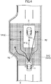
- FIG. 1 illustrates a configuration of an automotive arithmetic system SY (may be hereinafter simply referred to as an "arithmetic system SY") according to a first embodiment.
- the arithmetic system SY is, for example, an arithmetic system mounted on a four-wheel motor vehicle 1.
- the motor vehicle 1 is a motor vehicle that can be driven manually in accordance with the operation of an accelerator and the like by a driver, can assist the driver's operation during driving, and can be driven autonomously without the driver's operation.
- the motor vehicle 1 equipped with the arithmetic system SY may be referred to as a "subject vehicle 1" in order to distinguish the motor vehicle 1 from other vehicles.
- the arithmetic system SY determines a target motion of the motor vehicle 1 based on the outputs from a plurality of sensors and the like, and control the actuation of the devices.
- a vehicle external information acquisition device M1 including sensors and the like that output information of an environment outside the motor vehicle 1 to the arithmetic system SY includes, for example: (1) a plurality of cameras 50 provided to a body or the like of the motor vehicle 1 to take images of a vehicle external environment; (2) a plurality of radars 51 provided to the body or the like of the vehicle 1 to detect targets or the like outside the vehicle; (3) a vehicle speed sensor 52 that detects an absolute velocity of the motor vehicle 1; (4) an accelerator position sensor 53 that detects how much an accelerator pedal of the motor vehicle 1 is depressed; (5) a steering angle sensor 54 that detects a rotational angle (steering angle) of a steering wheel of the motor vehicle 1; (6) a brake sensor 55 that detects how much a brake pedal of the motor vehicle 1 is depressed; and (7) a position sensor 56 that detects the position of the motor vehicle 1 (vehicle position information) using Global Positioning System (GPS).
- GPS Global Positioning System
- the cameras 50 are arranged, for example, to be able to take images of the surroundings of the motor vehicle 1 at 360 degrees in the horizontal direction. Each of the cameras 50 generates image data by capturing an optical image showing the vehicle external environment. Each of the cameras 50 outputs the generated image data to a main arithmetic device 100.
- the cameras 50 are an example of a vehicle external information acquisition device that acquires information of the vehicle external environment.
- the radars 51 are arranged so that their detection range covers 360 degrees of the motor vehicle 1 in the horizontal direction, just like the cameras 50.
- the type of the radars 51 is not particularly limited. For example, millimeter wave radars or infrared radars can be adopted.
- the radars 51 are an example of the vehicle external information acquisition device that acquires information of the vehicle external environment.
- a vehicle internal information acquisition device M2 including sensors and the like that output information of an internal environment of the motor vehicle 1 to the arithmetic system SY includes: (1) an in-vehicle camera 58 provided for an in-vehicle mirror and/or dashboard of the motor vehicle 1 and captures an expression and posture of the driver and an environment inside the vehicle; and (2) an in-vehicle sensor 59 that acquires biological information (such as body temperature, heart rate, and respiration) of the driver.
- the vehicle internal information acquisition device M2 may include various sensors (not shown) attached to components of the motor vehicle to measure the state of the vehicle. Some of the sensors of the vehicle external information acquisition device M1 may also be used as the vehicle internal information acquisition device M2.
- Objects controlled by the arithmetic system SY include, for example, an engine 10, a brake 20, a steering 30, and a transmission 40.
- actuators AC the objects controlled by the arithmetic system SY (including the engine 10, the brake 20, the steering 30, and the transmission 40) will be collectively referred to as "actuators AC.”
- the engine 10 is a power drive source, and includes an internal combustion engine (a gasoline engine or a diesel engine).
- the arithmetic system SY outputs an engine output alteration signal to the engine 10 when the motor vehicle 1 needs to be accelerated or decelerated.
- the engine 10 is controlled by the degree of depression of the accelerator pedal by the driver during manual driving, but is controlled based on a target motion signal indicating a target motion outputted from the arithmetic system SY (will be hereinafter simply referred to as a "target motion signal”) during assisted driving and autonomous driving.
- a generator that generates electric power by the output of the engine 10 is connected to a rotational shaft of the engine 10.
- the brake 20 is an electric brake.
- the arithmetic system SY When the motor vehicle 1 needs to slow down, the arithmetic system SY outputs a brake request signal to the brake 20.
- the brake 20 that has received the brake request signal operates a brake actuator (not shown) based on the brake request signal to decelerate the motor vehicle 1.
- the brake 20 is controlled by the degree of depression of the brake pedal by the driver during the manual driving, but is controlled based on the target motion signal outputted from the arithmetic system SY during the assisted driving and the autonomous driving.
- the steering 30 is an electric power steering (EPS).
- EPS electric power steering
- the arithmetic system SY outputs a steering direction alteration signal to the steering 30 when the traveling direction of the motor vehicle 1 needs to be changed.
- the steering 30 is controlled by the degree of handling of a steering wheel (a so-called wheel) by the driver during the manual driving, but is controlled based on the target motion signal outputted from the arithmetic system SY during the assisted driving or the autonomous driving.
- the transmission 40 is a multi-speed transmission.
- the main arithmetic device 100 outputs a gear change signal to the transmission 40 in accordance with the driving force to be outputted.
- the transmission 40 is controlled by the handling of a shift lever by the driver and the degree of depression of the accelerator pedal by the driver during the manual driving, but is controlled based on the target motion calculated by the main arithmetic device 100 during the assisted driving and the autonomous driving.
- the arithmetic system SY outputs a control signal based on the output of the accelerator position sensor 53 or the like to the engine 10, for example.
- the arithmetic system SY sets a travel route of the motor vehicle 1, and outputs the control signal to the engine 10 and other actuators so that the motor vehicle 1 travels on the travel route.
- the arithmetic system SY includes a main arithmetic device 100, a backup arithmetic device 300, a monitoring unit 400, an abnormality detection unit 450, and a selector 500.
- the main arithmetic device 100 determines the target motion of the motor vehicle 1 based on the output from the vehicle external information acquisition device M1, and outputs a control signal for operating the actuators AC in accordance with the target motion.
- the backup arithmetic device 300 generates a safe route based on the output from the vehicle external information acquisition device M1, and determines a backup target motion which is a target motion for causing the motor vehicle to travel on the safe route. Further, the backup arithmetic device 300 outputs a backup control signal which is a control signal for operating the actuators AC in accordance with the backup target motion.
- the safe route mentioned herein refers to a travel route that the traveling motor vehicle takes until the motor vehicle stops at a safe stop position TP that satisfies a preset criterion.
- the safe stop position TP is not particularly limited as long as it is a position at which the motor vehicle 1 can safely stop, for example.
- the safe stop position TP examples include a vehicle free area on a road where no motor vehicles 1 are passing and a road shoulder 8 (see FIG. 3 ).
- the backup target motion includes (1) a target motion for causing the vehicle to immediately decelerate to a slow speed level and travel slowly to the safe stop position TP while blowing a horn with hazard lamps on, and (2) a target motion for causing the subject vehicle 1 to travel to the safe stop position TP taking a nearby traffic amount into consideration without disturbing nearby vehicles as possible.
- Each of the main arithmetic device 100 and the backup arithmetic device 300 is a microprocessor including one or more chips, and includes a CPU, a memory, and any other suitable elements. This configuration can reduce the risk of simultaneous failure of both devices.
- FIG. 1 shows the configuration that allows the function according to the present embodiment (the route generating function to be described later) to be executed, and does not necessarily show all the functions the main arithmetic device 100 and the backup arithmetic device 300 have.
- the monitoring unit 400 monitors the condition of the driver based on the output from the vehicle internal information acquisition device M2, and outputs the result to the abnormality detection unit 450.
- the abnormality detection unit 450 is configured to be able to detect a failure of the main arithmetic device 100.
- a method of detecting the failure of the main arithmetic device 100 is not particularly limited.
- applicable methods include a known hardware redundancy circuit (e.g., a dual core lockstep), monitoring of an operation result in a chip, monitoring of a flag register indicating an abnormality in a chip, a test circuit (logic build-in self-test (LBIST) circuit) in a chip, and mutual monitoring between chips.
- the abnormality detection unit 450 is configured to be able to detect that the driver is in an abnormal state based on the information of the driver received from the vehicle internal information acquisition device M2.
- the selector 500 which is realized by, for example, a selector circuit, selects either the control signal outputted from the main arithmetic device 100 or the backup control signal outputted from the backup arithmetic device 300 based on the detection result of the abnormality detection unit 450, and outputs the selected signal to the actuators AC of the motor vehicle 1. Specifically, the selector 500 selects and outputs the control signal outputted from the main arithmetic device 100 during a normal operation, and selects and outputs the backup control signal outputted from the backup arithmetic device 300 when either the main arithmetic device 100 or the driver is detected to be in an abnormal state.
- the main arithmetic device 100 includes a first arithmetic unit 110, a second arithmetic unit 120, a target motion determination unit 130, and an energy management unit 140.
- the first arithmetic unit 110 has the function of estimating the vehicle external environment using deep learning and generating a first route that is a route based on the estimated vehicle external environment. That is, the first arithmetic unit 110 functions as a route generation unit. Specifically, the first arithmetic unit 110 includes a vehicle external environment estimation unit 111, a first safe area setting unit 112, and a first route calculation unit 113.
- the "first route” will be described by way of examples in the section "2. Operation of Arithmetic System" to be described later.
- the vehicle external environment estimation unit 111 estimates the vehicle external environment through image recognition processing using deep learning based on the outputs of the cameras 50 and the radars 51. Specifically, the vehicle external environment estimation unit 111 constructs object identification information through deep learning based on image data from the cameras 50, and integrates the object identification information with positioning information from the radars to create a 3D map representing the vehicle external environment. Further, for example, estimation of objects' behavior based on deep learning is integrated with the 3D map to generate an environment model.
- the deep learning uses, for example, a multilayer neural network (deep neural network (DNN)). Examples of the multilayer neural network include a convolutional neural network (CNN).
- the first safe area setting unit 112 sets a first safe area SA1 (see FIG. 3 ) with respect to the vehicle external environment (e.g., a 3D map) estimated by the vehicle external environment estimation unit 111.
- the first safe area SA1 is set using a model constructed through deep learning as an area which the subject vehicle can pass.
- the model is constructed, for example, through reconstruction of a model previously constructed for each type of the motor vehicle 1 based on, e.g., the past driving history of the driver.
- the first safe area SA1 is what is called free space.
- the free space is an area on the road without any dynamic obstacle such as other vehicles or pedestrians, and any static obstacle such as a median strip or traffic poles.
- the first safe area SA1 may include a space of a road shoulder where the vehicle can stop in case of emergency.
- the first route calculation unit 113 calculates a first candidate route that passes within the first safe area SA1 set by the first safe area setting unit 112.
- the reinforcement learning is the function of setting an evaluation function for the result of a series of simulation (the candidate route in this example), and giving a high rating to the simulation result that meets a certain purpose, or a low rating to the simulation result that does not meet the certain purpose, thereby learning a candidate route that meets the purpose.
- An actual calculation method will be described later.
- the second arithmetic unit 120 has the function of recognizing an object outside the vehicle based on the output from the vehicle external information acquisition device M1 (e.g., the cameras 50 and the radars 51) according to a predetermined rule without using deep learning, and specifying a safe area based on the recognized object outside the vehicle.
- the second arithmetic unit 120 additionally has the function of generating a second route passing the specified safe area. That is, the second arithmetic unit 120 functions as a route generation unit.
- the second arithmetic unit 120 includes a target object recognition unit 121 (corresponding to an object recognition unit), a second safe area setting unit 122 (corresponding to a safe area setting unit), and a second route calculation unit 123.
- the target object recognition unit 121 recognizes a target object based on a target object recognition rule (corresponding to a predetermined rule). Examples of the target object include traveling vehicles, parked vehicles, or pedestrians present on a road. The target object recognition unit 121 also recognizes a relative distance and/or a relative speed between the subject vehicle and the target object. The target object recognition unit 121 also recognizes a roadway (including a lane marker and the like) based on the outputs from the cameras 50 and the radars 51.
- a target object recognition rule corresponding to a predetermined rule. Examples of the target object include traveling vehicles, parked vehicles, or pedestrians present on a road.
- the target object recognition unit 121 also recognizes a relative distance and/or a relative speed between the subject vehicle and the target object.
- the target object recognition unit 121 also recognizes a roadway (including a lane marker and the like) based on the outputs from the cameras 50 and the radars 51.
- the second safe area setting unit 122 sets a second safe area SA2 as an area where a collision with the target object recognized by the target object recognition unit 121 can be avoided.
- the second safe area SA2 is set based on a predetermined rule, e.g., an area of several meters around the target object is considered as a range where the collision is unavoidable.
- the second safe area setting unit 122 is configured to be able to set the second safe area SA2 in consideration of the speed of traveling vehicles and/or the speed of pedestrians.
- the "target object recognition rule" and the "predetermined rule” are obtained by applying, to a rule-based approach, a method of recognizing and avoiding the target object that has been adopted to the motor vehicles, and have a functional safety level equivalent to ASIL-D.
- the second safe area SA2 is what is called free space.
- the free space is an area on the road without any dynamic obstacle, such as other vehicles or pedestrians, and any static obstacle, such as a median strip or traffic poles.
- the second safe area SA2 may include a space of a road shoulder where the vehicle can stop in case of emergency.
- the second route calculation unit 123 calculates a second route (corresponding to a rule-based travel route) that passes within the second safe area SA2 set by the second safe area setting unit 122. An actual calculation method will be described later.
- the target motion determination unit 130 receives the outputs from the first and second arithmetic units 110 and 120, and determines the target motion of the motor vehicle 1. Receiving information of the first and second safe areas SA1 and SA2 and information of the first and second candidate routes in particular, the target motion determination unit 130 determines the target motion of the motor vehicle 1. Specifically, the target motion determination unit 130 sets a route that the motor vehicle 1 should take, and determines the operation amount (e.g., an engine torque or the operation amount of the brake actuator) required for the actuators AC (mainly, the engine 10, the brake 20, the steering 30, and the transmission 40) to cause the motor vehicle 1 to travel on the route.
- the operation amount e.g., an engine torque or the operation amount of the brake actuator
- the energy management unit 140 calculates the amount of control of the actuators AC at the highest energy efficiency to achieve the target motion determined by the target motion determination unit 130. Specifically, for example, the energy management unit 140 calculates the timing of opening or closing intake/exhaust valves (not shown) and the timing of injecting the fuel from injectors (not shown) at the most improved fuel efficiency to achieve the engine torque determined by the target motion determination unit 130. An operation example of the energy management unit 140 will be described more specifically later.
- Data of the target motion determined by the target motion determination unit 130 and data of the control amount calculated by the energy management unit 140 are outputted to the selector 500 as control signals for controlling the actuators AC.
- the backup arithmetic device 300 includes a backup arithmetic unit 310, a target motion determination unit 330, and an energy management unit 340.
- the backup arithmetic unit 310 has the function of generating a safe route, which is a route to the safe stop position TP, based on the output from the vehicle external information acquisition device M1. That is, the backup arithmetic unit 310 functions as a safe route generation unit. Specifically, the backup arithmetic unit 310 includes a vehicle external environment estimation unit 311, a third safe area setting unit 312, and a safe route calculation unit 313. The "safe route” will be described by way of examples in the section "2. Operation of Arithmetic System" to be described later.
- the vehicle external environment estimation unit 311 estimates the vehicle external environment using the data of the target object recognized by the target object recognition unit 121 of the second arithmetic unit 120. In addition, the vehicle external environment estimation unit 311 also recognizes a roadway (including a lane marker or the like) and a safe stop position TP at which the motor vehicle 1 can safely stop based on the output from the target object recognition unit 121.
- the safe stop position TP is not particularly limited as long as it is a position at which the motor vehicle 1 can safely stop. Examples of the safe stop position TP include a road shoulder 8 (see FIG. 3 ), and a vehicle free area on the road where no motor vehicles 1 are passing.
- the current position of the subject vehicle 1 or a position slightly ahead of the subject vehicle 1 can be the safe stop position TP.
- the motor vehicle 1 is stopped at such a place while operating a notification device such as hazard lamps, for example.
- the third safe area setting unit 312 sets a third safe area SA3 as an area where a collision with the target object recognized by the vehicle external environment estimation unit 311 can be avoided.
- the third safe area SA3 is set based on a predetermined rule, e.g., an area of several meters around the target object is considered as a range where the collision is unavoidable.
- the third safe area setting unit 312 and the second safe area setting unit 122 may be configured in the same manner. In this case, the third safe area SA3 and the second safe area SA2 may be designated as the same area.
- the second safe area setting unit 122 and the third safe area setting unit 312 may be realized by a common circuit.
- the second and third safe area setting units 122 and 312 are separated from the viewpoint of increasing resistance to failure.
- the "predetermined rule” mentioned herein is also the same as the "predetermined rule” described above, and has a functional safety level equivalent to ASIL-D.
- the safe route calculation unit 313 calculates a safe route RS which is a travel route that passes within the third safe area SA3 set by the third safe area setting unit 312 and reaches the safe stop position TP. An actual calculation method will be described later.
- the target motion determination unit 330 receives the output from the backup arithmetic unit 310, and determines the target motion of the motor vehicle 1. Receiving information of the third safe area SA3 and information of the safe stop position TP in particular, the target motion determination unit 330 determines the target motion of the motor vehicle 1. Specifically, the target motion determination unit 330 sets a safe route that the motor vehicle 1 should take to reach the safe stop position TP, and determines the operation amount (e.g., an engine torque or the operation amount of the brake actuator) required for the actuators AC (mainly, the engine 10, the brake 20, and the steering 30) to cause the motor vehicle 1 to travel on the route.
- the operation amount e.g., an engine torque or the operation amount of the brake actuator
- the energy management unit 340 calculates the amount of control of the actuators AC (such as the engine 10 described later) at the highest safety level and the highest energy efficiency to achieve the target motion determined by the target motion determination unit 330, while taking whether the subject vehicle 1 and the driver are in an abnormal state or not into account. Specifically, for example, the energy management unit 340 calculates the timing of opening or closing intake/exhaust valves (not shown) and the timing of injecting the fuel from injectors (not shown) at the most improved fuel efficiency to achieve the engine torque determined by the target motion determination unit 330. For example, if the driver is in an abnormal state, the energy management unit 340 calculates a method of controlling the actuators AC that can reduce a burden on the driver as small as possible.
- Data of the target motion determined by the target motion determination unit 330 and data of the control amount calculated by the energy management unit 340 are outputted to the selector 500 as control signals for controlling the actuators AC.
- a method of calculating the first and second routes will be described below with reference to FIG. 2 .
- the first and second routes are both calculated by the main arithmetic device 100.
- the first route to be calculated is a route passing within the first safe area SA1.
- the first route is calculated when the driving mode of the motor vehicle 1 is the assisted driving or the autonomous driving, and is not calculated in the manual driving.
- the first route calculation unit 113 executes grid point set processing based on roadway information.
- the grid area RW ranges from the periphery of the subject vehicle 1 to a predetermined distance ahead of the subject vehicle 1 along the roadway 5.
- the distance (longitudinal length) L is calculated based on the current vehicle speed of the subject vehicle 1.
- the distance L may be a predetermined fixed distance (e.g., 100 m) or may be a function of the vehicle speed (and acceleration).
- the width W of the grid area RW is set to be the width of the roadway 5.
- the grid area RW is divided into a large number of rectangular grid sections by a plurality of grid lines extending along the extending direction X and width direction (lateral direction) Y of the roadway 5. Points of intersection of the grid lines in the X and Y directions are grid points Gn. Intervals in the X and Y directions between the grid points Gn are respectively set to fixed values. In the present embodiment, for example, the grid interval in the X direction is 10 m, and the grid interval in the Y direction is 0.875 m.
- the grid interval may be a variable value according to the vehicle speed or the like. Since the roadway 5 shown in FIG. 2 is a straight section, the grid area RW and the grid sections are respectively set in a rectangular shape. When the roadway includes a curved section, the grid area and the grid sections may or may not be set in a rectangular shape.
- the first route calculation unit 113 sets a predetermined grid point GT in the grid area RW as a target reach position PE, and sets the target speed at the target reach position PE (GT) in accordance with an external signal.
- the external signal is, for example, a guidance signal that guides the subject vehicle 1 to a destination (e.g., a parking area) transmitted from a navigation system (not shown) mounted on the subject vehicle 1.
- the first route calculation unit 113 executes arithmetic processing for route setting.
- the first route calculation unit 113 creates candidate routes from the current position PS (start point) of the subject vehicle 1 to each grid point Gn (end point) in the grid area RW.
- the first route calculation unit 113 also sets speed information at the end point.
- the start point and the end point are connected via one or more grid points Gn or no grid points Gn.
- the first route calculation unit 113 calculates position information by setting a route curve pattern that connects the grid points, and calculates a profile of speed change to be in conformity with a speed change pattern.
- the speed change pattern is generated as a combination of sharp acceleration (e.g., 0.3 G), slow acceleration (e.g., 0.1 G), constant vehicle speed, slow deceleration (e.g., -0.1 G), and sharp deceleration (e.g., -0.3 G), and is set not for each grid but for a predetermined length (e.g., 50 m to 100 m) of the first candidate route R1m.
- each of the first candidate routes R1m is a route from the start point to a position at which the vehicle arrives after a fixed time (e.g., three seconds).
- the first route calculation unit 113 calculates a route cost taken by the obtained first candidate routes R1m.
- the first route calculation unit 113 calculates, for each sampling point SP, an inertia force Fi due to the motion of the vehicle 1, collision probability Pc with an obstacle (the other vehicle 3 in this example), and an impact force Fc applied to the occupant upon the collision (or a reaction force against the collision), and calculates external forces FC to be applied to the occupant based on these values, thereby obtaining the sum of the external forces FC (absolute values) at all the sampling points SP on the first candidate route R1m as the route cost (candidate route cost) EPm of the first candidate route R1m.
- the first route calculation unit 113 outputs all the first candidate routes R1m to the target motion determination unit 130 together with their route cost information.
- the first route is set in this manner.
- the second route is basically calculated in the same manner as the first route. As the second route, a route having the lowest route cost is selected and outputted to the target motion determination unit 130.
- the routes outputted to the target motion determination unit 130 include the first route calculated by the first arithmetic unit 110 and the second route calculated by the second arithmetic unit 120, but the target motion determination unit 130 basically adopts the first route. This is because the first route that is set using deep learning or reinforcement learning is more likely to be a route that reflects the driver's intention, i.e., a route that does not cause the driver to feel redundancy, such as being too cautious in avoiding the obstacle.
- FIG. 3 illustrates the first safe area SA1 set by the first safe area setting unit 112 and the second safe area SA2 set by the second safe area setting unit 122.
- the first safe area SA1 is a hatched portion in FIG. 3
- the second safe area SA2 (see FIG. 4 ) is the hatched portion except for the inside of a dotted frame in FIG. 3 .
- part of the other vehicle 3 is included in the first safe area SA1. This may occur when the width of the other vehicle 3 cannot be accurately estimated in image recognition by deep learning.
- the function using deep learning is considered to be equivalent to ASIL-B in the functional safety level (ASIL) defined by Functional Safety for Road Vehicles standard (ISO 26262). Thus, some contrivance is required to improve the functional safety level.
- ASIL functional safety level defined by Functional Safety for Road Vehicles standard
- the target motion determination unit 130 of the main arithmetic device 100 selects the first route as the route that the motor vehicle 1 (the subject vehicle 1) should take, and determines the target motion of the motor vehicle 1 so that the motor vehicle 1 takes the first route.
- the first candidate routes R11, R12, and R13 are set by the first route calculation unit 113 as illustrated in FIG. 4 .
- the routes R11 and R12 partially deviate from the second safe area SA2, but the route R13 passes within the second safe area SA2.
- the target motion determination unit 130 does not select the routes R11 and R12 deviating from the second safe area SA2 as the route that the motor vehicle 1 should take, but selects the route R13 as the route that the motor vehicle 1 should take.
- the target motion determination unit 130 selects the second candidate route R2 having the lowest route cost among the plurality of second candidate routes calculated by the second arithmetic unit 120 as the route that the motor vehicle 1 should take.
- the target object recognition unit 121 recognizes the target object based on the existing predetermined rule, and thus, can accurately recognize the size of the target object.
- the second safe area setting unit 122 sets the second safe area SA2 based on a predetermined rule, e.g., an area of several meters around the target object is considered as a range where the collision is unavoidable.
- the second candidate route is a route that can ensure a sufficient distance from the other vehicle 3 even when avoiding the collision with the other vehicle 3.
- the function of the second arithmetic unit 120 can be equivalent to ASIL-D.
- the target motion determination unit 130 selects the second candidate route as the route that the motor vehicle 1 should take, so that the motor vehicle 1 can travel on a highly safe route. Accordingly, the main arithmetic device 100 having the function of using deep learning can improve the functional safety level.
- the safe route is calculated by the backup arithmetic device 300.
- the safe route calculation unit 313 calculates, among the candidate routes in the third safe area SA3 specified by the third safe area setting unit 312, a safe route that the motor vehicle 1 (the subject vehicle 1) should take.
- the backup arithmetic device 300 sets the safe stop position TP, which is a position where the motor vehicle 1 can safely stop, and sets a travel route passing within the third safe area SA3 and heading to the safe stop position TP as the safe route RS (see FIG. 4 ). Therefore, in principle, the route having the lowest route cost among the candidate routes passing within the third safe area SA3 and heading to the safe stop position TP is selected as the safe route RS, and is outputted to the target motion determination unit 330.
- the safe route RS outputted by the backup arithmetic device 300 is used in an abnormal situation, for example, the case where a trouble such as a failure in the main arithmetic device 100 has occurred, or the case where the driver cannot continue driving any more. Therefore, the backup arithmetic device 300 may set the safe stop position TP and/or the safe route RS in consideration of the information about abnormality.
- the backup arithmetic device 300 may set the road shoulder 8 where the vehicle can safely stop at the nearest distance as the safe stop position TP as shown in FIG. 4 , and set the shortest route to the road shoulder 8 as the safe route RS.
- hazard lamps may be turned on to warn the nearby vehicles of the abnormal state, and then the vehicle may slow down and stop in the same lane.
- a hospital or a nearest public facility may be set as the safe stop position TP in cooperation with the navigation system and GPS measurement results, and the vehicle may automatically travel to the set safe stop position TP while passing within the third safe area SA3 specified at the position of the subject vehicle 1.
- the safe route calculation unit 313 may set the safe route RS while taking the abnormal state of the subject vehicle 1 and the condition of the driver into consideration.
- a processing operation of the arithmetic system SY for determining the driving route of the motor vehicle 1 will be described below with reference to the flowcharts of FIGS. 6 to 8 .
- the motor vehicle 1 is assumed to be in the assisted driving mode or the autonomous driving mode.
- step S100 the processing by the main arithmetic device 100
- step S200 the processing by the backup arithmetic device 300
- step S100 The processing by the main arithmetic device 100 in step S100 will be described below with reference to FIG. 7 .
- step S101 the main arithmetic device 100 reads information from the vehicle external information acquisition device M1 (the cameras 50, the radars 51, and the sensors 52 to 56).
- the main arithmetic device 100 calculates the first candidate route and the second candidate route in parallel.
- step S102 the first arithmetic unit 110 estimates the vehicle external environment using deep learning.
- the first arithmetic unit 110 sets the first safe area SA1.
- the first arithmetic unit 110 calculates a first candidate route using reinforcement learning, and outputs the first candidate route to the target motion determination unit 130.
- step S105 the second arithmetic unit 120 recognizes the target object based on a predetermined rule.
- step S106 the second arithmetic unit 120 sets the second safe area SA2.
- step S107 the second arithmetic unit 120 calculates a second candidate route based on a predetermined rule, and outputs the second candidate route to the target motion determination unit 130.
- the target motion determination unit 130 determines whether or not the first candidate route received from the first arithmetic unit 110 is within the second safe area SA2. In this step S108, if there is a route which is entirely included in the second safe area SA2 among the first candidate routes received from the first arithmetic unit 110 (YES is selected), the flow proceeds to step S109. On the other hand, in step S108, if every first candidate route received from the first arithmetic unit 110 at least partially deviates from the second safe area SA2 (NO is selected), the flow proceeds to step S110.
- step S109 the target motion determination unit 130 selects the first candidate route as a route that the motor vehicle 1 should take.
- step S110 the target motion determination unit 130 selects the second candidate route as a route that the motor vehicle 1 should take.
- the target motion determination unit 130 calculates the target motion of the motor vehicle 1 based on the result of selection in step S109.
- the energy management unit 140 sets the target control amount at the highest energy efficiency to achieve the target motion calculated in step S111. Specifically, for example, when outputting the required driving force determined by the target motion determination unit 130, the energy management unit 140 calculates the number of speeds of the transmission 40, the timing of opening or closing intake/exhaust valves (not shown), and the timing of injecting the fuel from injectors (not shown), so that the fuel consumption of the engine 10 is minimized. When outputting a target braking force, the energy management unit 140 generates the braking force by increasing the amount of regenerative power of the generator connected to the engine 10 or the driving load of a cooling compressor to minimize the engine brake.
- the energy management unit 140 controls the vehicle speed and the steering angle so that the rolling resistance applied to the motor vehicle 1 during cornering is minimized. Specifically, the generation of the braking force and the timing of the steering are controlled so that rolling is induced in synchronization with pitching that lowers a front portion of the motor vehicle 1 to give rise to diagonal rolling. Giving rise to the diagonal rolling increases the load applied to the turning outer front wheel. This allows the vehicle to corner at a small steering angle, and can reduce the rolling resistance applied to the motor vehicle 1.
- step S113 the main arithmetic device 100 controls the operation of the actuators AC so that the control amount of the actuators AC becomes the target control amount calculated in step S112.
- step S113 the flow proceeds to step S300 in FIG. 6 .
- step S200 the processing by the backup arithmetic device 300 in step S200 will be described below.
- the backup arithmetic device 300 acquires information of a target object recognized based on the vehicle external information acquisition device M1 (reference character SE indicates the flow of a signal in FIG. 1 ). For example, the backup arithmetic device 300 acquires the information of the target object recognized by the target object recognition unit 121 of the second arithmetic unit 120.
- the backup arithmetic device 300 may have the function similar to that of the target object recognition unit 121 of the second arithmetic unit 120, and may acquire information of the target object recognized based on the vehicle external information acquisition device M1 by itself.
- step S304 the backup arithmetic unit 310 searches for a free space where the vehicle can safely stop, and sets a safe stop position TP in the free space.
- the backup arithmetic unit 310 cooperates with GPS or the car navigation system, and acquires information of the nearest facility to be set as the safe stop position TP when the driver is in an abnormal state.
- step S305 the backup arithmetic unit 310 sets a third safe area SA3.
- the target motion determination unit 130 selects a route within the third safe area SA3 from the safe routes received from the backup arithmetic unit 310, and sets the selected safe route as the route that the motor vehicle 1 should take.
- the target motion determination unit 330 calculates a target motion for causing the motor vehicle 1 to travel the route selected in step S308.
- step S312 the energy management unit 340 sets the target control amount at the highest energy efficiency to achieve the target motion calculated in step S311, and the flow proceeds to step S300 in FIG. 6 .
- step S300 the abnormality detection unit 450 in the arithmetic system SY determines whether the driver and/or the subject vehicle 1 are/is detected to be in an abnormal state or not.
- step S300 if no abnormality is detected by the abnormality detection unit 450 (NO is selected), the flow proceeds to "normal operation mode" in step S400.
- the selector 500 selects and outputs the control signal for realizing the target motion output from the main arithmetic device.
- step S300 If the abnormality detection unit 450 has detected an abnormality in step S300 (YES is selected), the flow proceeds to a safe operation mode in step S500.
- the selector 500 selects and outputs the control signal for realizing the target motion output from the main arithmetic device.
- the automotive arithmetic system SY mounted on the motor vehicle 1 includes the main arithmetic device 100, the backup arithmetic device 300, and the selector 500.
- the main arithmetic device 100 includes the first route calculation unit 113 (corresponding to a route generation unit) that estimates the vehicle external environment using deep learning based on the output from the vehicle external information acquisition device M1 that acquires information of the vehicle external environment, and generates the first route based on the estimated vehicle external environment.
- the main arithmetic device 100 determines a target motion using the output of the first route calculation unit 113, and outputs a control signal for achieving the target motion.
- the backup arithmetic device 300 includes the safe route calculation unit 313 (corresponding to a safe route generation unit) that generates a safe route, which is a travel route on which the vehicle travels to the safe stop position TP where the vehicle can safely stop, based on the output from the vehicle external information acquisition device M1.
- the backup arithmetic device 300 determines a backup target motion for causing the vehicle to travel on the safe route, and outputs a backup control signal for achieving the backup target motion.
- the selector 500 receives the control signal outputted from the main arithmetic device 100 and the backup control signal outputted from the backup arithmetic device 300, selects and outputs the control signal outputted from the main arithmetic device 100 during the normal operation, or selects and outputs the backup control signal outputted from the backup arithmetic device 300 when a failure of the main arithmetic device 100 is detected.
- the main arithmetic device 100 having the function of using deep learning can improve the functional safety level.
- FIG. 10 illustrates a configuration of an automotive arithmetic system SY (may be hereinafter simply referred to as an "arithmetic system SY") according to a second embodiment.
- an automotive arithmetic system SY may be hereinafter simply referred to as an "arithmetic system SY"
- FIG. 10 components that are common with those shown in FIG. 1 are denoted by the same reference numerals, and may not be described in detail.
- the arithmetic system SY includes a main arithmetic device 100, a backup arithmetic device 300, and an override processing unit 410.
- the arithmetic system SY includes a processor SY2 and a memory SY4.
- the memory SY4 stores modules each of which is a software program executable by the processor SY2.
- the function of each unit of the arithmetic system SY shown in FIG. 10 is achieved, for example, by the processor SY2 executing the modules stored in the memory SY4.
- the memory SY4 stores data of a model used by the arithmetic system SY Note that a plurality of processors SY2 and a plurality of memories SY4 may be provided.
- the main arithmetic device 100 includes a first arithmetic unit 110 and a second arithmetic unit 120.
- the first arithmetic unit 110 (corresponding to a main arithmetic unit) has the function of estimating the vehicle external environment including a road and an obstacle using deep learning, and generating a first route that is a travel route of the motor vehicle based on the estimated vehicle external environment. Note that the specific configuration and operation of the first arithmetic unit 110 are the same as those of the first embodiment, and will not be described in detail below.
- the first candidate route (corresponding to a travel route of the motor vehicle) generated by the first route calculation unit 113 of the first arithmetic unit 110 is outputted to the override processing unit 410.
- the second arithmetic unit 120 (corresponding to an auxiliary arithmetic unit) has the function of estimating the presence of the road and the obstacle based on the output from the vehicle external information acquisition device M1 (e.g., the cameras 50 and the radars 51) according to a predetermined rule, which is preset, without using deep learning, and generating a rule-based travel route in a free space on the road where no obstacle is present.
- a predetermined rule which is preset, without using deep learning, and generating a rule-based travel route in a free space on the road where no obstacle is present.
- the second candidate route generated by the second route calculation unit 123 of the second arithmetic unit 120 is outputted to the override processing unit 410.
- the backup arithmetic device 300 (corresponding to a safe route generation unit) has the function of generating a safe route, which is a travel route that the motor vehicle takes until the motor vehicle stops at a safe stop position that satisfies a preset criterion, based on the output from the vehicle external information acquisition device M1 without using deep learning. Note that the specific configuration and operation of the backup arithmetic device 300 are the same as those of the first embodiment, and will not be described in detail below.
- the safe route RS generated by the safe route calculation unit 313 of the backup arithmetic device 300 is outputted to the override processing unit 410.
- the override processing unit 410 includes an override unit 420, a target motion determination unit 130, and an energy management unit 140.
- the override unit 420 receives the first candidate route generated by the first route calculation unit 113, the second candidate route generated by the second route calculation unit 123, and the safe route RS generated by the safe route calculation unit 313, prioritizes one of the routes over the others, and outputs the prioritized route.
- the override unit 420 receives the output from the vehicle internal information acquisition device M2 and determines the route to be prioritized, based on the output. More specifically, the override unit 420 may prioritize the safe route RS generated by the safe route calculation unit 313 if the vehicle is determined to have failed based on the state of the vehicle received from the vehicle internal information acquisition device M2 (e.g., the measurement result of the in-vehicle sensor). Alternatively, the override unit 420 may prioritize the safe route RS if the driver's driving ability is determined to have decreased based on the state of the vehicle received from the vehicle internal information acquisition device M2. Specific examples of the operation of the override unit 420 will be described later with reference to FIGS. 12A and 12B .
- the target motion determination unit 130 receives the output from the override unit 420, and determines the target motion of the motor vehicle 1. In the same manner as described in the first embodiment, the target motion determination unit 130 sets a route that the motor vehicle 1 should take, and determines the operation amount required for the actuators AC to cause the motor vehicle 1 to travel on the route.
- the energy management unit 140 calculates the amount of control of the actuators AC at the highest energy efficiency to achieve the target motion determined by the target motion determination unit 130.
- An operation example of the energy management unit 140 will be described more specifically in the following section of "Example Introduced to Actual System.”
- Data of the target motion determined by the target motion determination unit 130 and data of the control amount calculated by the energy management unit 140 are outputted to the actuators AC as control signals for controlling the actuators AC.
- the override processing unit 410 may cause at least one of a lighting device 41, a sounding device 42, or a wireless communication device 43 mounted on the motor vehicle to operate in a mode different from a predetermined normal traveling mode.
- the override unit 420 outputs the safe route RS as the prioritized route
- the motor vehicle may immediately decelerate to a slow speed level, while flashing the lighting device 41 and blowing a horn as the sounding device 42.
- the wireless communication device 43 configured to be able to communicate with the outside may inform a medical emergency facility or an administrative server of an event occurring in the vehicle (e.g., the state of a vehicle failure and the condition of the driver).
- FIGS. 12A and 12B are collectively referred to as FIG. 12 .
- FIG. 12 operations that are common with those shown in FIGS. 6 to 8 are denoted by the same reference numerals, and may not be described in detail.
- step S101 the main arithmetic device 100 reads information from the vehicle external information acquisition device M1 (the cameras 50, the radars 51, and the sensors 52 to 56).
- Steps S102 to S104 are a series of processing performed by the first arithmetic unit 110, and are the same as those shown in FIG. 7 .
- Steps S105 to S107 are a series of processing performed by the second arithmetic unit 120, and are the same as those shown in FIG. 7 .
- the information of the target object recognized by the target object recognition unit 121 of the second arithmetic unit 120 in step S105 is outputted to the backup arithmetic unit 310.
- the backup arithmetic unit 310 performs the same processing as that shown in FIG. 7 as steps S304, S305, and S308 based on the information of the target object received from the target object recognition unit 121.
- the arithmetic system SY determines whether the driver and/or the subject vehicle 1 are/is detected to be in an abnormal state or not. In the subsequent step S108, the arithmetic system SY determines whether the first candidate route received from the first arithmetic unit 110 is within the second safe area SA2 or not. Based on the results of the determination in the two steps, the override unit 420 prioritizes one of (1) the first candidate route generated by the first route calculation unit 113, (2) the second candidate route generated by the second route calculation unit 123, or (3) the safe route RS generated by the safe route calculation unit 313, and outputs the prioritized route.
- the override unit 420 selects the safe route RS (described as a third candidate route in FIG. 12B ) generated by the safe route calculation unit 313 (step S310).
- step S108 If no abnormality is detected in the output of the vehicle internal information acquisition device M2 (NO is selected), the flow proceeds to step S108.
- step S108 if there is a route which is entirely included in the second safe area SA2 among the first candidate routes received from the first arithmetic unit 110 (YES is selected), the override unit 420 selects and outputs one of the first candidate routes generated by the first route calculation unit 113 (step S109). On the other hand, in step S108, if every first candidate route received from the first arithmetic unit 110 at least partially deviates from the second safe area SA2 (NO is selected), the override unit 420 selects and outputs one of the second candidate routes generated by the second route calculation unit 123 (step S110).
- the target motion determination unit 130 calculates the target motion of the motor vehicle 1.
- the energy management unit 140 sets the target control amount at the highest energy efficiency to achieve the target motion calculated in step S111 in the same manner as described in the first embodiment.
- the arithmetic device 100 controls the operation of the actuators AC so that the control amount of the actuators AC becomes the target control amount calculated in step S112.
- the main arithmetic device 100 having the function of using deep learning can improve the functional safety level.
- the energy management unit 140 sets the target control amount at the highest energy efficiency to achieve the target motion after the target motion determination unit 130 has determined the target motion.
- the present disclosure is not limited thereto, and the energy management unit 140 may be omitted.
- the target motion determination unit 130 may set the target control amount for achieving the target motion.
- main arithmetic device 100 and the backup arithmetic device 300 are configured of different chips, for example, but the present disclosure is not limited thereto.
- the main arithmetic device and the backup arithmetic device may be physically separated from each other and housed in the same housing or package.
- the abnormality detection unit 450 may be configured to detect an abnormality in the output itself of the vehicle external information acquisition device M1 or the output itself of the vehicle internal information acquisition device M2.
- the abnormality detection unit 450 may be configured to be able to detect a state where a problem has occurred in the route generation by the main arithmetic device 100, such as when the camera 50 has failed or no signals are inputted from the camera 50.
- the selector 500 may be configured to select and output the backup control signal outputted from the backup arithmetic device 300 when the abnormality detection unit 450 has detected an abnormality in the output of the vehicle external information acquisition device M1 such as the camera 50.
- the detection result of the abnormality detection unit 450 may be given to both of the main arithmetic device 100 and the backup arithmetic device 300.
- the backup arithmetic device 300 stops outputting, and the main arithmetic device 100 outputs the control signal to the actuators AC.
- the main arithmetic device 100 may stop outputting, and the backup arithmetic device 300 may output the backup control signal to the actuators AC.
- the first route calculation unit 113 of the first arithmetic unit 110 may set the first route in consideration of the safe area set by the second safe area setting unit 122.
- FIGS. 9A and 9B are collectively referred to as FIG. 9 .
- the automotive arithmetic system SY of the present disclosure (will be hereinafter simply referred to as an "arithmetic system SY") is functionally divided into: (1) a configuration (may be hereinafter referred to as a “cognitive block B1") for recognizing the vehicle external environment and the vehicle internal environment (including the driver's condition); (2) a configuration (may be hereinafter referred to as a “determination block B2”) for considering various states and situations based on the recognition result of the cognitive block B1 and determining the operation of the motor vehicle 1; and (3) a configuration (may be hereinafter referred to as an "operation block B3”) for specifically generating signals and data to be transmitted to the actuators based on the determination in the determination block B2.
- a configuration may be hereinafter referred to as a “cognitive block B1" for recognizing the vehicle external environment and the vehicle internal environment (including the driver's condition)
- a configuration (may be hereinafter referred to as a "determination block B2”) for considering
- the arithmetic system SY includes: (1) a main arithmetic unit 700 including the cognitive block B1, the determination block B2, and the operation block B3 for realizing autonomous driving during the normal operation; (2) a safety function unit 800 that mainly functions to complement the cognitive block B1 and determination block B2 of the main arithmetic unit 700; and (3) a backup safety function unit 900 that causes the motor vehicle 1 to move to a safe position when an abnormal situation has occurred, such as a failure in the functions of the main arithmetic unit 700 and the safety function unit 800.
- the cognitive block B1 and determination block B2 of the main arithmetic unit 700 execute processing using various models constructed through deep learning using a neural network.
- the processing using such models enables driving control based on comprehensive determination of the state of the vehicle, the vehicle external environment, and the conditions of the driver, i.e., control of a large amount of input information in cooperation in real time.
- the recognition of the vehicle external environment and the route calculation using the deep learning are still under development, and considered to remain at around ASIL-B.
- ASIL information of each block is described as reference information in FIG. 9 , the present disclosure is not limited thereto, and each block may have a functional safety level different from that shown in FIG. 9 .
- the arithmetic system SY of the present disclosure assumes that the deep learning executed by the main arithmetic unit 700 may possibly lead to determination or processing deviating from a certain acceptable range (hereinafter simply referred to as “deviating processing"), and monitors the deviating processing. If the deviating processing is detected, the deviating processing is replaced or complemented with determination or processing by the safety function unit 800 having the functional safety level equivalent to ASIL-D.
- the safety function unit 800 is configured to: (1) recognize an object outside of the vehicle (referred to as a "target object” in the present disclosure) based on a target recognition method which has been adopted to the motor vehicles; and (2) set a safe area which the vehicle can safely pass by a method that has been adopted to the motor vehicles, and then set a route passing the safe area as a travel route that the motor vehicle should take.
- a target object an object outside of the vehicle
- the safety function unit 800 is configured to: (1) recognize an object outside of the vehicle (referred to as a "target object" in the present disclosure) based on a target recognition method which has been adopted to the motor vehicles; and (2) set a safe area which the vehicle can safely pass by a method that has been adopted to the motor vehicles, and then set a route passing the safe area as a travel route that the motor vehicle should take.
- Another feature of the arithmetic system SY is that the main arithmetic unit 700 and the safety function unit 800 perform processing for the same purpose (e.g., route generation) in parallel based on the same input information (including information acquired by the vehicle external information acquisition device M1 and the vehicle internal information acquisition device M2).
- This configuration makes it possible to monitor the deviating processing that is derived from the main arithmetic unit 700, and employ the determination or processing by the safety function unit 800, or cause the main arithmetic unit 700 to re-calculate, as necessary.
- the main arithmetic unit 700 and the safety function unit 800 may be configured as one or more chips in which their functions are combined together (hereinafter, the combination may also be referred to as a "vehicle control function"), or the main arithmetic unit 700 and the safety function unit 800 may be configured as independent chips.
- a route which is set by the main arithmetic unit 700 and deviates from the safe area set by the safety function unit 800, is replaced with a rule-based route generated by the safety function unit 800.
- the arithmetic system SY is provided with a backup safety function unit 900 (corresponding to the backup arithmetic device 30) to be able to address a situation in which both of the main arithmetic unit 700 and the safety function unit 800 fail.
- the backup safety function unit 900 has the function of generating a rule-based route based on the information outside the vehicle and executing the vehicle control until the vehicle stops at a safe position, as a separate configuration from the main arithmetic unit 700 and the safety function unit 800.
- the backup safety function unit 900 is configured as separate devices (chips).
- the vehicle can stop at a safe place.
- the provision of the backup safety function unit 900 makes it possible to complement the failure of one of the vehicle control function or the backup function by the other, and secure the safety operation at the time of failure.
- the arithmetic system SY receives, as input signals, data acquired by the vehicle external information acquisition device M1 that acquires the information of the environment outside the motor vehicle, and data acquired by the vehicle internal information acquisition device M2 that acquires the information on the environment inside the motor vehicle.
- the arithmetic system SY may receive, as the input signal, information inputted from a system or a service connected to an external network (e.g., the Internet), such as the cloud computing (referred to as "EXTERNAL INPUT" in FIG. 9 ).
- Examples of the vehicle external information acquisition device M1 include (1) a plurality of cameras 50, (2) a plurality of radars 51, (3) a mechanical sensor 520 such as a vehicle speed sensor 52, (4) a driver input unit 530 such as an accelerator position sensor 53, a steering angle sensor 54, and a brake sensor 55, and (5) a position sensor 56 including a positioning system such as GPS.
- Examples of the vehicle internal information acquisition device M2 include an in-vehicle camera 58 and an in-vehicle sensor 59.
- the in-vehicle sensor 59 includes, for example, a sensor that detects a driver's operation of various operation objects such as an accelerator pedal, a brake pedal, a steering wheel, and various switches.
- the vehicle internal information acquisition device M2 is not shown in FIG. 9 .
- a configuration example of the main arithmetic unit 700 and the route generation using deep learning by the main arithmetic unit 700 will be described below.
- the main arithmetic unit 700 includes an object recognition unit 701 that recognizes an object (target object) outside the vehicle based on the input from the cameras 50 and/or the radars 51.
- the object recognition unit 701 has the function of recognizing an object outside the vehicle based on an image (including video) of the outside the vehicle taken by the cameras 50 and/or on a peak list of reflected waves using the radars 51.
- the main arithmetic unit 700 has the function of determining what the recognized object is using deep learning.
- a known object recognition technique based on an image or radio waves can be applied to the object recognition unit 701.
- the result of recognition by the object recognition unit 701 is transmitted to a map generation unit 702.
- the map generation unit 702 divides an area around the subject vehicle into a plurality of areas (e.g., front, right, left, and rear areas), and performs map generation processing for each area.
- the object information recognized by the cameras 50 and the object information recognized by the radars 51 are integrated together for each area and reflected on the map.
- the vehicle external environment estimation unit 703 uses the map generated by the map generation unit 702 to estimate the vehicle external environment through image recognition processing using deep learning. Specifically, the vehicle external environment estimation unit 703 generates a 3D map representing the vehicle external environment through the image recognition processing based on an environment model 704 constructed using deep learning.
- a multilayer neural network e.g., a deep neural network (DNN)
- DNN deep neural network
- Examples of the multilayer neural network include a convolutional neural network (CNN).
- the vehicle external environment estimation unit 703 (1) combines the maps for the areas and generates the integrated map representing the surroundings of the subject vehicle 1, (2) estimates the displacements of the distances, directions, and relative speeds of moving objects within the integrated map with respect to the subject vehicle 1, and (3) incorporates the result into the vehicle external environment model 704.
- the vehicle external environment estimation unit 703 (4) estimates the position of the subject vehicle 1 on the integrated map based on a combination of highly accurate map information taken from the inside or outside of the vehicle, positional information obtained by the GPS or the like, vehicle speed information, and six-axis information, and (5) calculates the route costs described above, and (6) incorporates the result into the external environment model 704 together with the motion information of the subject vehicle 1 obtained by the various sensors.
- the external environment model 704 is updated by the vehicle external environment estimation unit 703 as needed, and is used for the route generation by the route generation unit 705.
- the signals of the positioning system such as the GPS, and the data, e.g., for car navigation transmitted from the external network are transmitted to a route searching unit 706.
- the route searching unit 706 searches for a wide-area route of the vehicle using the signals of the positioning system such as the GPS or the data, for example, for the navigation system transmitted from the external network.
- the route generation unit 705 generates the travel route of the vehicle based on the external environment model 704 and the output from the route searching unit 706.
- a specific route searching method by the main arithmetic unit 700 has been described as a calculation method of the first route in the section of "2-1. Calculation of First Route and Second Route" of the embodiment.
- the function described so far is an example of the route generation by deep learning, and is route generation that realizes a functional safety level equivalent to ASIL-B.
- a configuration of the safety function unit 800 and rule-based route generation by the safety function unit 800 will be described below.
- the safety function unit 800 includes, just like the main arithmetic unit 700, an object recognition unit 801 that recognizes an object (target object) outside the vehicle based on the input from the cameras 50 and/or the radars 51.
- the safety function unit 800 recognizes an object outside the vehicle in the same manner as the main arithmetic unit 700, and then determines what the recognized object is by a known rule-based method without using deep learning. For example, the safety function unit 800 determines what the recognized object is through a known discriminator having a functional safety level equivalent to ASIL-D.
- the object recognized by the object recognition unit 801 is classified into a moving object or a stationary object.
- the classification is executed by a circuit block denoted by reference numeral 802 and indicated as "CLASSIFICATION OF MOVING OBJECT/STATIONARY OBJECT.”
- a circuit block denoted by reference numeral 802 and indicated as "CLASSIFICATION OF MOVING OBJECT/STATIONARY OBJECT.”
- an area around the subject vehicle is divided into a plurality of areas (e.g., front, right, left, and rear areas)
- the object information recognized by the cameras 50 and the object information recognized by the radars 51 are integrated for each area
- classification information of the moving and stationary objects is generated for each area.
- the classification results for each area are integrated together, and (5) are managed on a grid map, such as that shown in FIG.
- the safety function unit 800 detects the state of the vehicle based on the vehicle speed information and the six-axis information, and uses the detected vehicle state as associated information of the subject vehicle 1 for the route generation.
- the safety function unit 800 generates a route based on the estimated position of the subject vehicle with respect to the moving object/stationary object and the search result of the safe area.
- the safe area corresponds to the second safe area SA2 described in the embodiments.
- the setting of the safe area is performed in the same manner as the setting of the second safe area SA2 by the second safe area setting unit 122 in the above embodiments.
- the route generation is also performed in the same manner as the route generation by the second route calculation unit 123, and thus, the detailed description thereof is omitted.
- the function described so far is an example of the rule-based route generation, and is route generation that realizes a functional safety level equivalent to ASIL-D.
- the routes generated by the main arithmetic unit 700 and the safety function unit 800 are sent to the target motion determination unit 730, and an optimum target motion is determined in accordance with the result of comparison between the routes. For example, as described in the embodiment, when the route generated by the main arithmetic unit 700 deviates from the safe area searched by the safety function unit 800, the route generated by the safety function unit 800 is adopted.
- the target motion determination unit 730, a vehicle kinetic energy operation unit 740, and an energy management unit 750 correspond to the target motion determination unit 130 and the energy management unit 140 described in the aforementioned embodiment, and will not be described in detail below.
- the backup safety function unit 900 is provided with a configuration required to enable an operation of moving to and stopping at a minimum safe stop position based on a rule. This configuration can be roughly realized by the function similar to the safety function unit 800.
- the object is classified into a moving object or a stationary object in the backup safety function unit 900 based on the result of recognition by the object recognition unit 801.
- the classification is executed by a circuit block denoted by reference numeral 903 and indicated as "CLASSIFICATION OF MOVING OBJECT/STATIONARY OBJECT.”
- the object recognition unit 801 may be common to the safety function unit 800, or may be separately provided in the backup safety function unit 900.
- the backup safety function unit 900 includes a vehicle state measurement unit 901 that measures the state of the vehicle, and a driver's operation recognition unit 902 that recognizes the state of operation by the driver.
- the vehicle state measurement unit 901 acquires the state of the vehicle based on the vehicle speed information and the six-axis information so that the vehicle's state is used as associated information of the subject vehicle 1 for the route generation.
- the driver's operation recognition unit 902 is a function corresponding to the monitoring unit 400.
- the other functions are provided independently of the main arithmetic unit 700 and the safety function unit 800, but the substantial functions are the same as those of the configuration described above, and thus, are not described in detail.
- the present disclosure is useful as an automotive arithmetic system mounted on a motor vehicle.
Abstract
Description
- The present disclosure relates to an automotive arithmetic system used for autonomous driving of a motor vehicle, for example.
- A technique of environmental recognition inside and outside a vehicle using deep learning based on a neural network has also been applied to motor vehicles.
- For example, Patent Document 1 discloses an estimation device that estimates an occupant's condition with respect to vehicle equipment and includes a memory and a processing unit. The memory stores a model constructed through deep learning using a neural network, and the processing unit receives an image including the equipment, estimates the occupant's condition using the model, and outputs first information indicating a skeleton position of a specific part of the occupant and second information indicating the occupant's condition with respect to the equipment.
- Patent Document 1:
Japanese Unexamined Patent Publication No. 2018-132996 - In recent years, development of autonomous driving systems has been promoted nationally. In general, an autonomous driving system obtains information of a vehicle external environment using a camera or any other suitable means, and calculates a route that the motor vehicle should take based on the obtained information of the vehicle external environment. What is important for the route calculation is the recognition of the vehicle external environment, and use of deep learning for the recognition of the vehicle exterior environment has been considered.
- As a concept of software design for functional safety of an arithmetic device that performs autonomous driving, for example, Functional Safety for Road Vehicles standard (ISO 26262) defines Automotive Safety Integrity Level (ASIL) as a hazard assessment index regarding the application of functional safety of a plurality of modules constituting a program. According to ASIL, development at a design level corresponding to a functional safety level from ASIL-A to ASIL-D is required.
- However, the recognition of the vehicle external environment and the route calculation using deep learning are still under development, and are considered to remain at around ASIL-B. Therefore, in order to give a functional safety level of about ASIL-D to a motor vehicle having the autonomous driving function, it is insufficient to configure the arithmetic device only with the function using deep learning.
- The present disclosure has been made in view of the foregoing background, and an object thereof is to improve the functional safety level of an automotive arithmetic system having the function of using deep learning.
- In order to achieve the object, the present disclosure is directed to an automotive arithmetic system mounted on a motor vehicle. The automotive arithmetic system includes: a main arithmetic unit that estimates a vehicle external environment including a road and an obstacle using deep learning based on an output from a vehicle external information acquisition device that acquires information of the vehicle external environment, and generates a travel route of the motor vehicle based on the estimated vehicle external environment; an auxiliary arithmetic unit that estimates the presence of the road and the obstacle based on the output from the vehicle external information acquisition device according to a predetermined rule without using deep learning, and generates a rule-based travel route in a free space on the road where no obstacle is present; a safe route generation unit that generates a safe route, which is a travel route that the motor vehicle takes until the motor vehicle stops at a safe stop position that satisfies a preset criterion, based on the output from the vehicle external information acquisition device without using deep learning; and an override processing unit that prioritizes one of the travel route generated by the main arithmetic unit, the rule-based travel route generated by the auxiliary arithmetic unit, or the safe route generated by the safe route generation unit, and determines a target motion of the motor vehicle so that the motor vehicle travels on the prioritized route.
- According to this configuration, the main arithmetic unit that uses deep learning and the auxiliary arithmetic unit and the safe route generation unit that do not use deep learning are provided, and the override processing unit prioritizes any one of the routes over the others. Specifically, the travel route that ensures safety can be selected based on the state of the vehicle. This can improve the functional safety level of the automotive arithmetic system having the function of using deep learning.
- In addition, when determining the target motion, the safe route generation unit generates the safe route based on the output of the vehicle external information acquisition device, and determines the target motion for taking the safe route according to the information of the vehicle internal environment. Thus, the target motion can be determined to be suitable for the vehicle internal environment.
- The information of the vehicle internal environment is a concept including information indicating the state of the vehicle and information indicating the condition of the driver. The information indicating the state of the vehicle includes, for example, information acquired from various sensors or any other devices attached to the vehicle, and information of an operation performed on the vehicle by the driver. The information indicating the condition of the driver includes, for example, information acquired from a camera that takes images inside the vehicle, various in-vehicle sensors for obtaining biological information of the driver, or a sensor for measuring a driving environment inside the vehicle such as temperature and humidity inside the vehicle, and information of an operation (handling) performed on the vehicle by the driver.
- In one embodiment of the automotive arithmetic system, the override processing unit determines the route to be prioritized based on an output from a vehicle internal information acquisition device that acquires vehicle internal environment information including a state of a vehicle and a condition of a driver.
- According to this configuration, the target motion can be determined to be suitable for the vehicle internal environment. Specifically, for example, the override processing unit may prioritize the safe route if the vehicle is determined to have failed based on the state of the vehicle received from the vehicle internal information acquisition device. Alternatively, for example, the override processing unit may prioritize the safe route if a driving ability of the driver is determined to have decreased based on the state of the vehicle received from the vehicle internal information acquisition device.
- Further, the override processing unit that has prioritized the safe route may cause at least one of a lighting device, a sounding device, or a wireless communication device mounted on the motor vehicle to operate in a mode different from a predetermined normal traveling mode.
- According to this configuration, if the vehicle has failed or the driving ability of the driver has decreased, the safety level can be improved in consideration of the surrounding vehicles. For example, when the wireless communication device is operated, the wireless communication device can inform the outside of the vehicle failure or the decrease in the driver's driving ability.
- As can be seen from the foregoing description, the present disclosure can improve the safety level of an arithmetic device having the function of using deep learning, and can cause the arithmetic device to behave safely in accordance with the states of the traveling vehicle and passengers.
-
-
FIG. 1 is a block diagram illustrating a functional configuration of an automotive arithmetic system according to a first embodiment. -
FIG. 2 is a view illustrating an example of a travel route set by the arithmetic system. -
FIG. 3 is a view showing a comparison between a safe area set by a first arithmetic unit and a safe area set by a second arithmetic unit. -
FIG. 4 is a view illustrating an example of relationship between a candidate route calculated based on a vehicle external environment estimated through deep learning and a safe area. -
FIG. 5 is another view illustrating an example of relationship between the candidate route calculated based on the vehicle external environment estimated through deep learning and the safe area. -
FIG. 6 is a flowchart illustrating operation processing of the arithmetic system. -
FIG. 7 is a flowchart of how a driving route of a motor vehicle is determined. -
FIG. 8 is a flowchart of how a driving route of a motor vehicle is determined. -
FIG. 9A is a block diagram illustrating a functional configuration of an example introduced into an actual system. -
FIG. 9B is a block diagram illustrating a functional configuration of an example introduced into an actual system. -
FIG. 10 is a block diagram illustrating a functional configuration of an automotive arithmetic system according to a second embodiment. -
FIG. 11 is a view illustrating an exemplary configuration of a motor vehicle equipped with the arithmetic system of the second embodiment. -
FIG. 12A is a flowchart illustrating operation processing of the arithmetic system of the second embodiment. -
FIG. 12B is a flowchart illustrating operation processing of the arithmetic system of the second embodiment. - Exemplary embodiments will be described in detail below with reference to the drawings.
-
FIG. 1 illustrates a configuration of an automotive arithmetic system SY (may be hereinafter simply referred to as an "arithmetic system SY") according to a first embodiment. The arithmetic system SY is, for example, an arithmetic system mounted on a four-wheel motor vehicle 1. The motor vehicle 1 is a motor vehicle that can be driven manually in accordance with the operation of an accelerator and the like by a driver, can assist the driver's operation during driving, and can be driven autonomously without the driver's operation. In the following description, the motor vehicle 1 equipped with the arithmetic system SY may be referred to as a "subject vehicle 1" in order to distinguish the motor vehicle 1 from other vehicles. - The arithmetic system SY determines a target motion of the motor vehicle 1 based on the outputs from a plurality of sensors and the like, and control the actuation of the devices.
- A vehicle external information acquisition device M1 including sensors and the like that output information of an environment outside the motor vehicle 1 to the arithmetic system SY includes, for example: (1) a plurality of
cameras 50 provided to a body or the like of the motor vehicle 1 to take images of a vehicle external environment; (2) a plurality ofradars 51 provided to the body or the like of the vehicle 1 to detect targets or the like outside the vehicle; (3) avehicle speed sensor 52 that detects an absolute velocity of the motor vehicle 1; (4) anaccelerator position sensor 53 that detects how much an accelerator pedal of the motor vehicle 1 is depressed; (5) asteering angle sensor 54 that detects a rotational angle (steering angle) of a steering wheel of the motor vehicle 1; (6) abrake sensor 55 that detects how much a brake pedal of the motor vehicle 1 is depressed; and (7) aposition sensor 56 that detects the position of the motor vehicle 1 (vehicle position information) using Global Positioning System (GPS). - The
cameras 50 are arranged, for example, to be able to take images of the surroundings of the motor vehicle 1 at 360 degrees in the horizontal direction. Each of thecameras 50 generates image data by capturing an optical image showing the vehicle external environment. Each of thecameras 50 outputs the generated image data to a mainarithmetic device 100. Thecameras 50 are an example of a vehicle external information acquisition device that acquires information of the vehicle external environment. - The
radars 51 are arranged so that their detection range covers 360 degrees of the motor vehicle 1 in the horizontal direction, just like thecameras 50. The type of theradars 51 is not particularly limited. For example, millimeter wave radars or infrared radars can be adopted. Theradars 51 are an example of the vehicle external information acquisition device that acquires information of the vehicle external environment. - A vehicle internal information acquisition device M2 including sensors and the like that output information of an internal environment of the motor vehicle 1 to the arithmetic system SY includes: (1) an in-
vehicle camera 58 provided for an in-vehicle mirror and/or dashboard of the motor vehicle 1 and captures an expression and posture of the driver and an environment inside the vehicle; and (2) an in-vehicle sensor 59 that acquires biological information (such as body temperature, heart rate, and respiration) of the driver. The vehicle internal information acquisition device M2 may include various sensors (not shown) attached to components of the motor vehicle to measure the state of the vehicle. Some of the sensors of the vehicle external information acquisition device M1 may also be used as the vehicle internal information acquisition device M2. - Objects controlled by the arithmetic system SY include, for example, an
engine 10, abrake 20, asteering 30, and atransmission 40. In the following description, for convenience of explanation, the objects controlled by the arithmetic system SY (including theengine 10, thebrake 20, the steering 30, and the transmission 40) will be collectively referred to as "actuators AC." - The
engine 10 is a power drive source, and includes an internal combustion engine (a gasoline engine or a diesel engine). The arithmetic system SY outputs an engine output alteration signal to theengine 10 when the motor vehicle 1 needs to be accelerated or decelerated. Theengine 10 is controlled by the degree of depression of the accelerator pedal by the driver during manual driving, but is controlled based on a target motion signal indicating a target motion outputted from the arithmetic system SY (will be hereinafter simply referred to as a "target motion signal") during assisted driving and autonomous driving. Although not shown, a generator that generates electric power by the output of theengine 10 is connected to a rotational shaft of theengine 10. - The
brake 20 is an electric brake. When the motor vehicle 1 needs to slow down, the arithmetic system SY outputs a brake request signal to thebrake 20. Thebrake 20 that has received the brake request signal operates a brake actuator (not shown) based on the brake request signal to decelerate the motor vehicle 1. Thebrake 20 is controlled by the degree of depression of the brake pedal by the driver during the manual driving, but is controlled based on the target motion signal outputted from the arithmetic system SY during the assisted driving and the autonomous driving. - The steering 30 is an electric power steering (EPS). The arithmetic system SY outputs a steering direction alteration signal to the
steering 30 when the traveling direction of the motor vehicle 1 needs to be changed. The steering 30 is controlled by the degree of handling of a steering wheel (a so-called wheel) by the driver during the manual driving, but is controlled based on the target motion signal outputted from the arithmetic system SY during the assisted driving or the autonomous driving. - The
transmission 40 is a multi-speed transmission. The mainarithmetic device 100 outputs a gear change signal to thetransmission 40 in accordance with the driving force to be outputted. Thetransmission 40 is controlled by the handling of a shift lever by the driver and the degree of depression of the accelerator pedal by the driver during the manual driving, but is controlled based on the target motion calculated by the mainarithmetic device 100 during the assisted driving and the autonomous driving. - During the manual driving, the arithmetic system SY outputs a control signal based on the output of the
accelerator position sensor 53 or the like to theengine 10, for example. During the assisted driving or the autonomous driving, the arithmetic system SY sets a travel route of the motor vehicle 1, and outputs the control signal to theengine 10 and other actuators so that the motor vehicle 1 travels on the travel route. - As shown in
FIG. 1 , the arithmetic system SY includes a mainarithmetic device 100, a backuparithmetic device 300, amonitoring unit 400, anabnormality detection unit 450, and aselector 500. - When performing the assisted driving or the autonomous driving, the main
arithmetic device 100 determines the target motion of the motor vehicle 1 based on the output from the vehicle external information acquisition device M1, and outputs a control signal for operating the actuators AC in accordance with the target motion. - The backup
arithmetic device 300 generates a safe route based on the output from the vehicle external information acquisition device M1, and determines a backup target motion which is a target motion for causing the motor vehicle to travel on the safe route. Further, the backuparithmetic device 300 outputs a backup control signal which is a control signal for operating the actuators AC in accordance with the backup target motion. The safe route mentioned herein refers to a travel route that the traveling motor vehicle takes until the motor vehicle stops at a safe stop position TP that satisfies a preset criterion. The safe stop position TP is not particularly limited as long as it is a position at which the motor vehicle 1 can safely stop, for example. Examples of the safe stop position TP include a vehicle free area on a road where no motor vehicles 1 are passing and a road shoulder 8 (seeFIG. 3 ). For example, when an abnormality is detected by anabnormality detection unit 450 which will be described later, the backup target motion includes (1) a target motion for causing the vehicle to immediately decelerate to a slow speed level and travel slowly to the safe stop position TP while blowing a horn with hazard lamps on, and (2) a target motion for causing the subject vehicle 1 to travel to the safe stop position TP taking a nearby traffic amount into consideration without disturbing nearby vehicles as possible. - Each of the main
arithmetic device 100 and the backuparithmetic device 300 is a microprocessor including one or more chips, and includes a CPU, a memory, and any other suitable elements. This configuration can reduce the risk of simultaneous failure of both devices.FIG. 1 shows the configuration that allows the function according to the present embodiment (the route generating function to be described later) to be executed, and does not necessarily show all the functions the mainarithmetic device 100 and the backuparithmetic device 300 have. - The
monitoring unit 400 monitors the condition of the driver based on the output from the vehicle internal information acquisition device M2, and outputs the result to theabnormality detection unit 450. - The
abnormality detection unit 450 is configured to be able to detect a failure of the mainarithmetic device 100. A method of detecting the failure of the mainarithmetic device 100 is not particularly limited. For example, applicable methods include a known hardware redundancy circuit (e.g., a dual core lockstep), monitoring of an operation result in a chip, monitoring of a flag register indicating an abnormality in a chip, a test circuit (logic build-in self-test (LBIST) circuit) in a chip, and mutual monitoring between chips. Further, theabnormality detection unit 450 is configured to be able to detect that the driver is in an abnormal state based on the information of the driver received from the vehicle internal information acquisition device M2. - The
selector 500, which is realized by, for example, a selector circuit, selects either the control signal outputted from the mainarithmetic device 100 or the backup control signal outputted from the backuparithmetic device 300 based on the detection result of theabnormality detection unit 450, and outputs the selected signal to the actuators AC of the motor vehicle 1. Specifically, theselector 500 selects and outputs the control signal outputted from the mainarithmetic device 100 during a normal operation, and selects and outputs the backup control signal outputted from the backuparithmetic device 300 when either the mainarithmetic device 100 or the driver is detected to be in an abnormal state. - Components of the arithmetic system SY will be described in further detail below.
- The main
arithmetic device 100 includes a firstarithmetic unit 110, a secondarithmetic unit 120, a targetmotion determination unit 130, and anenergy management unit 140. - The first
arithmetic unit 110 has the function of estimating the vehicle external environment using deep learning and generating a first route that is a route based on the estimated vehicle external environment. That is, the firstarithmetic unit 110 functions as a route generation unit. Specifically, the firstarithmetic unit 110 includes a vehicle externalenvironment estimation unit 111, a first safearea setting unit 112, and a firstroute calculation unit 113. The "first route" will be described by way of examples in the section "2. Operation of Arithmetic System" to be described later. - The vehicle external
environment estimation unit 111 estimates the vehicle external environment through image recognition processing using deep learning based on the outputs of thecameras 50 and theradars 51. Specifically, the vehicle externalenvironment estimation unit 111 constructs object identification information through deep learning based on image data from thecameras 50, and integrates the object identification information with positioning information from the radars to create a 3D map representing the vehicle external environment. Further, for example, estimation of objects' behavior based on deep learning is integrated with the 3D map to generate an environment model. The deep learning uses, for example, a multilayer neural network (deep neural network (DNN)). Examples of the multilayer neural network include a convolutional neural network (CNN). - The first safe
area setting unit 112 sets a first safe area SA1 (seeFIG. 3 ) with respect to the vehicle external environment (e.g., a 3D map) estimated by the vehicle externalenvironment estimation unit 111. The first safe area SA1 is set using a model constructed through deep learning as an area which the subject vehicle can pass. The model is constructed, for example, through reconstruction of a model previously constructed for each type of the motor vehicle 1 based on, e.g., the past driving history of the driver. The first safe area SA1 is what is called free space. For example, the free space is an area on the road without any dynamic obstacle such as other vehicles or pedestrians, and any static obstacle such as a median strip or traffic poles. The first safe area SA1 may include a space of a road shoulder where the vehicle can stop in case of emergency. - Using reinforcement learning, the first
route calculation unit 113 calculates a first candidate route that passes within the first safe area SA1 set by the first safearea setting unit 112. The reinforcement learning is the function of setting an evaluation function for the result of a series of simulation (the candidate route in this example), and giving a high rating to the simulation result that meets a certain purpose, or a low rating to the simulation result that does not meet the certain purpose, thereby learning a candidate route that meets the purpose. An actual calculation method will be described later. - The second
arithmetic unit 120 has the function of recognizing an object outside the vehicle based on the output from the vehicle external information acquisition device M1 (e.g., thecameras 50 and the radars 51) according to a predetermined rule without using deep learning, and specifying a safe area based on the recognized object outside the vehicle. The secondarithmetic unit 120 additionally has the function of generating a second route passing the specified safe area. That is, the secondarithmetic unit 120 functions as a route generation unit. Specifically, the secondarithmetic unit 120 includes a target object recognition unit 121 (corresponding to an object recognition unit), a second safe area setting unit 122 (corresponding to a safe area setting unit), and a secondroute calculation unit 123. - The target
object recognition unit 121 recognizes a target object based on a target object recognition rule (corresponding to a predetermined rule). Examples of the target object include traveling vehicles, parked vehicles, or pedestrians present on a road. The targetobject recognition unit 121 also recognizes a relative distance and/or a relative speed between the subject vehicle and the target object. The targetobject recognition unit 121 also recognizes a roadway (including a lane marker and the like) based on the outputs from thecameras 50 and theradars 51. - The second safe
area setting unit 122 sets a second safe area SA2 as an area where a collision with the target object recognized by the targetobject recognition unit 121 can be avoided. The second safe area SA2 is set based on a predetermined rule, e.g., an area of several meters around the target object is considered as a range where the collision is unavoidable. The second safearea setting unit 122 is configured to be able to set the second safe area SA2 in consideration of the speed of traveling vehicles and/or the speed of pedestrians. Note that the "target object recognition rule" and the "predetermined rule" are obtained by applying, to a rule-based approach, a method of recognizing and avoiding the target object that has been adopted to the motor vehicles, and have a functional safety level equivalent to ASIL-D. Just like the first safe area SA1, the second safe area SA2 is what is called free space. For example, the free space is an area on the road without any dynamic obstacle, such as other vehicles or pedestrians, and any static obstacle, such as a median strip or traffic poles. The second safe area SA2 may include a space of a road shoulder where the vehicle can stop in case of emergency. - The second
route calculation unit 123 calculates a second route (corresponding to a rule-based travel route) that passes within the second safe area SA2 set by the second safearea setting unit 122. An actual calculation method will be described later. - The target
motion determination unit 130 receives the outputs from the first and secondarithmetic units motion determination unit 130 determines the target motion of the motor vehicle 1. Specifically, the targetmotion determination unit 130 sets a route that the motor vehicle 1 should take, and determines the operation amount (e.g., an engine torque or the operation amount of the brake actuator) required for the actuators AC (mainly, theengine 10, thebrake 20, the steering 30, and the transmission 40) to cause the motor vehicle 1 to travel on the route. - The
energy management unit 140 calculates the amount of control of the actuators AC at the highest energy efficiency to achieve the target motion determined by the targetmotion determination unit 130. Specifically, for example, theenergy management unit 140 calculates the timing of opening or closing intake/exhaust valves (not shown) and the timing of injecting the fuel from injectors (not shown) at the most improved fuel efficiency to achieve the engine torque determined by the targetmotion determination unit 130. An operation example of theenergy management unit 140 will be described more specifically later. - Data of the target motion determined by the target
motion determination unit 130 and data of the control amount calculated by theenergy management unit 140 are outputted to theselector 500 as control signals for controlling the actuators AC. - The backup
arithmetic device 300 includes a backuparithmetic unit 310, a targetmotion determination unit 330, and anenergy management unit 340. - The backup
arithmetic unit 310 has the function of generating a safe route, which is a route to the safe stop position TP, based on the output from the vehicle external information acquisition device M1. That is, the backuparithmetic unit 310 functions as a safe route generation unit. Specifically, the backuparithmetic unit 310 includes a vehicle externalenvironment estimation unit 311, a third safearea setting unit 312, and a saferoute calculation unit 313. The "safe route" will be described by way of examples in the section "2. Operation of Arithmetic System" to be described later. - The vehicle external
environment estimation unit 311 estimates the vehicle external environment using the data of the target object recognized by the targetobject recognition unit 121 of the secondarithmetic unit 120. In addition, the vehicle externalenvironment estimation unit 311 also recognizes a roadway (including a lane marker or the like) and a safe stop position TP at which the motor vehicle 1 can safely stop based on the output from the targetobject recognition unit 121. The safe stop position TP is not particularly limited as long as it is a position at which the motor vehicle 1 can safely stop. Examples of the safe stop position TP include a road shoulder 8 (seeFIG. 3 ), and a vehicle free area on the road where no motor vehicles 1 are passing. For example, when no other vehicles are found in a range of several meters around the subject vehicle 1, the current position of the subject vehicle 1 or a position slightly ahead of the subject vehicle 1 can be the safe stop position TP. The motor vehicle 1 is stopped at such a place while operating a notification device such as hazard lamps, for example. - The third safe
area setting unit 312 sets a third safe area SA3 as an area where a collision with the target object recognized by the vehicle externalenvironment estimation unit 311 can be avoided. The third safe area SA3 is set based on a predetermined rule, e.g., an area of several meters around the target object is considered as a range where the collision is unavoidable. The third safearea setting unit 312 and the second safearea setting unit 122 may be configured in the same manner. In this case, the third safe area SA3 and the second safe area SA2 may be designated as the same area. The second safearea setting unit 122 and the third safearea setting unit 312 may be realized by a common circuit. However, in a preferred embodiment, the second and third safearea setting units - The safe
route calculation unit 313 calculates a safe route RS which is a travel route that passes within the third safe area SA3 set by the third safearea setting unit 312 and reaches the safe stop position TP. An actual calculation method will be described later. - The target
motion determination unit 330 receives the output from the backuparithmetic unit 310, and determines the target motion of the motor vehicle 1. Receiving information of the third safe area SA3 and information of the safe stop position TP in particular, the targetmotion determination unit 330 determines the target motion of the motor vehicle 1. Specifically, the targetmotion determination unit 330 sets a safe route that the motor vehicle 1 should take to reach the safe stop position TP, and determines the operation amount (e.g., an engine torque or the operation amount of the brake actuator) required for the actuators AC (mainly, theengine 10, thebrake 20, and the steering 30) to cause the motor vehicle 1 to travel on the route. - The
energy management unit 340 calculates the amount of control of the actuators AC (such as theengine 10 described later) at the highest safety level and the highest energy efficiency to achieve the target motion determined by the targetmotion determination unit 330, while taking whether the subject vehicle 1 and the driver are in an abnormal state or not into account. Specifically, for example, theenergy management unit 340 calculates the timing of opening or closing intake/exhaust valves (not shown) and the timing of injecting the fuel from injectors (not shown) at the most improved fuel efficiency to achieve the engine torque determined by the targetmotion determination unit 330. For example, if the driver is in an abnormal state, theenergy management unit 340 calculates a method of controlling the actuators AC that can reduce a burden on the driver as small as possible. - Data of the target motion determined by the target
motion determination unit 330 and data of the control amount calculated by theenergy management unit 340 are outputted to theselector 500 as control signals for controlling the actuators AC. - The operation of the arithmetic system will be described below with reference to the drawings.
- A method of calculating the first and second routes will be described below with reference to
FIG. 2 . As described above, the first and second routes are both calculated by the mainarithmetic device 100. - Although the first safe area SA1 is not illustrated in the example of
FIG. 2 , the first route to be calculated is a route passing within the first safe area SA1. The first route is calculated when the driving mode of the motor vehicle 1 is the assisted driving or the autonomous driving, and is not calculated in the manual driving. - First, as shown in
FIG. 2 , the firstroute calculation unit 113 executes grid point set processing based on roadway information. In the grid point set processing, the mainarithmetic device 100 first specifies the shape of the roadway 5 (i.e., the direction in which theroadway 5 extends and the width of the roadway), and sets a grid area RW including grid points Gn (n = 1, 2, ..., N) on theroadway 5. - The grid area RW ranges from the periphery of the subject vehicle 1 to a predetermined distance ahead of the subject vehicle 1 along the
roadway 5. The distance (longitudinal length) L is calculated based on the current vehicle speed of the subject vehicle 1. In the present embodiment, the distance L (L = V × t) is a distance that the vehicle is expected to travel at the current vehicle speed (V) for a predetermined fixed time t (e.g., three seconds). However, the distance L may be a predetermined fixed distance (e.g., 100 m) or may be a function of the vehicle speed (and acceleration). The width W of the grid area RW is set to be the width of theroadway 5. - The grid area RW is divided into a large number of rectangular grid sections by a plurality of grid lines extending along the extending direction X and width direction (lateral direction) Y of the
roadway 5. Points of intersection of the grid lines in the X and Y directions are grid points Gn. Intervals in the X and Y directions between the grid points Gn are respectively set to fixed values. In the present embodiment, for example, the grid interval in the X direction is 10 m, and the grid interval in the Y direction is 0.875 m. - The grid interval may be a variable value according to the vehicle speed or the like. Since the
roadway 5 shown inFIG. 2 is a straight section, the grid area RW and the grid sections are respectively set in a rectangular shape. When the roadway includes a curved section, the grid area and the grid sections may or may not be set in a rectangular shape. - Next, in the calculation of the first candidate route, the first
route calculation unit 113 sets a predetermined grid point GT in the grid area RW as a target reach position PE, and sets the target speed at the target reach position PE (GT) in accordance with an external signal. The external signal is, for example, a guidance signal that guides the subject vehicle 1 to a destination (e.g., a parking area) transmitted from a navigation system (not shown) mounted on the subject vehicle 1. - Next, the first
route calculation unit 113 executes arithmetic processing for route setting. In this arithmetic processing, the firstroute calculation unit 113 first executes candidate route calculation processing for calculating a plurality of first candidate routes R1m (m = 1,2, 3, ...). This processing is similar to the calculation of the candidate route using the existing state lattice method. - The outline of the calculation of the candidate routes will be described below. The first
route calculation unit 113 creates candidate routes from the current position PS (start point) of the subject vehicle 1 to each grid point Gn (end point) in the grid area RW. The firstroute calculation unit 113 also sets speed information at the end point. - The start point and the end point are connected via one or more grid points Gn or no grid points Gn. For each of the first candidate routes R1m, the first
route calculation unit 113 calculates position information by setting a route curve pattern that connects the grid points, and calculates a profile of speed change to be in conformity with a speed change pattern. The speed change pattern is generated as a combination of sharp acceleration (e.g., 0.3 G), slow acceleration (e.g., 0.1 G), constant vehicle speed, slow deceleration (e.g., -0.1 G), and sharp deceleration (e.g., -0.3 G), and is set not for each grid but for a predetermined length (e.g., 50 m to 100 m) of the first candidate route R1m. - Further, the first
route calculation unit 113 sets sampling points SP for each candidate route, and calculates speed information at each sampling point SP.FIG. 2 shows only three first candidate routes R11, R12, R13 of a large number of candidate routes. In the present embodiment, each of the first candidate routes R1m is a route from the start point to a position at which the vehicle arrives after a fixed time (e.g., three seconds). - Next, the first
route calculation unit 113 calculates a route cost taken by the obtained first candidate routes R1m. In the calculation of the route cost of each first candidate route R1m, the firstroute calculation unit 113 calculates, for each sampling point SP, an inertia force Fi due to the motion of the vehicle 1, collision probability Pc with an obstacle (theother vehicle 3 in this example), and an impact force Fc applied to the occupant upon the collision (or a reaction force against the collision), and calculates external forces FC to be applied to the occupant based on these values, thereby obtaining the sum of the external forces FC (absolute values) at all the sampling points SP on the first candidate route R1m as the route cost (candidate route cost) EPm of the first candidate route R1m. - Then, the first
route calculation unit 113 outputs all the first candidate routes R1m to the targetmotion determination unit 130 together with their route cost information. - The first route is set in this manner.
- The second route is basically calculated in the same manner as the first route. As the second route, a route having the lowest route cost is selected and outputted to the target
motion determination unit 130. - In the first embodiment, the routes outputted to the target
motion determination unit 130 include the first route calculated by the firstarithmetic unit 110 and the second route calculated by the secondarithmetic unit 120, but the targetmotion determination unit 130 basically adopts the first route. This is because the first route that is set using deep learning or reinforcement learning is more likely to be a route that reflects the driver's intention, i.e., a route that does not cause the driver to feel redundancy, such as being too cautious in avoiding the obstacle. - However, the recognition of the vehicle external environment using deep learning is still under development. That is, with an environment model constructed by using deep learning, accurate information can be calculated in a range similar to information on which the environment model is based. However, if an actual vehicle external environment greatly differs from the environment model, a vehicle external environment that is deviated from the actual vehicle external environment may be estimated.
- For example,
FIG. 3 illustrates the first safe area SA1 set by the first safearea setting unit 112 and the second safe area SA2 set by the second safearea setting unit 122. The first safe area SA1 is a hatched portion inFIG. 3 , and the second safe area SA2 (seeFIG. 4 ) is the hatched portion except for the inside of a dotted frame inFIG. 3 . As shown inFIG. 3 , part of theother vehicle 3 is included in the first safe area SA1. This may occur when the width of theother vehicle 3 cannot be accurately estimated in image recognition by deep learning. - As described above, in the recognition of the vehicle external environment using deep learning, the vehicle external environment deviating from the actual vehicle external environment may be estimated in some cases. Therefore, the function using deep learning is considered to be equivalent to ASIL-B in the functional safety level (ASIL) defined by Functional Safety for Road Vehicles standard (ISO 26262). Thus, some contrivance is required to improve the functional safety level.
- Therefore, in the first embodiment, when the first route is within the second safe area SA2, the target
motion determination unit 130 of the mainarithmetic device 100 selects the first route as the route that the motor vehicle 1 (the subject vehicle 1) should take, and determines the target motion of the motor vehicle 1 so that the motor vehicle 1 takes the first route. On the other hand, when the first route deviates from the second safe area SA2, the targetmotion determination unit 130 does not select the first route as the route that the motor vehicle 1 should take. More specifically, if all of the plurality of first candidate routes R1n (n = 1, 2, 3, ...) set as the candidate routes deviate from the second safe area SA2 in the calculation of the first route, the targetmotion determination unit 130 selects the second candidate route as the route that the motor vehicle 1 should take. - For example, provided that the first candidate routes R11, R12, and R13 are set by the first
route calculation unit 113 as illustrated inFIG. 4 . Among the three first candidate routes R11 to R13, the routes R11 and R12 partially deviate from the second safe area SA2, but the route R13 passes within the second safe area SA2. At this time, the targetmotion determination unit 130 does not select the routes R11 and R12 deviating from the second safe area SA2 as the route that the motor vehicle 1 should take, but selects the route R13 as the route that the motor vehicle 1 should take. - On the other hand, provided that the first candidate routes R14, R15, and R16 are set by the first
route calculation unit 113 as illustrated inFIG. 5 . All the three first candidate routes R14 to R16 partially deviate from the second safe area SA2. At this time, the targetmotion determination unit 130 selects the second candidate route R2 having the lowest route cost among the plurality of second candidate routes calculated by the secondarithmetic unit 120 as the route that the motor vehicle 1 should take. - The target
object recognition unit 121 recognizes the target object based on the existing predetermined rule, and thus, can accurately recognize the size of the target object. In addition, the second safearea setting unit 122 sets the second safe area SA2 based on a predetermined rule, e.g., an area of several meters around the target object is considered as a range where the collision is unavoidable. Thus, the second candidate route is a route that can ensure a sufficient distance from theother vehicle 3 even when avoiding the collision with theother vehicle 3. Specifically, the function of the secondarithmetic unit 120 can be equivalent to ASIL-D. Therefore, if all the plurality of first candidate routes R1n set as the candidate routes deviate from the second safe area SA2 in the calculation of the first route, the targetmotion determination unit 130 selects the second candidate route as the route that the motor vehicle 1 should take, so that the motor vehicle 1 can travel on a highly safe route. Accordingly, the mainarithmetic device 100 having the function of using deep learning can improve the functional safety level. - A method of calculating the safe route will be described below. As described above, the safe route is calculated by the backup
arithmetic device 300. - Since the safe route is basically calculated in the same manner as the above-described second route, the differences will be mainly described below, and the description of the common configuration and operation may be omitted.
- First, the setting of the grid area RW including the grid points Gn (n = 1, 2, ..., N) on the
roadway 5 and the candidate route calculation processing for calculating a plurality of candidate routes can be executed by the common technique. - Then, the safe
route calculation unit 313 calculates, among the candidate routes in the third safe area SA3 specified by the third safearea setting unit 312, a safe route that the motor vehicle 1 (the subject vehicle 1) should take. - As described above, the backup
arithmetic device 300 sets the safe stop position TP, which is a position where the motor vehicle 1 can safely stop, and sets a travel route passing within the third safe area SA3 and heading to the safe stop position TP as the safe route RS (seeFIG. 4 ). Therefore, in principle, the route having the lowest route cost among the candidate routes passing within the third safe area SA3 and heading to the safe stop position TP is selected as the safe route RS, and is outputted to the targetmotion determination unit 330. - The safe route RS outputted by the backup
arithmetic device 300 is used in an abnormal situation, for example, the case where a trouble such as a failure in the mainarithmetic device 100 has occurred, or the case where the driver cannot continue driving any more. Therefore, the backuparithmetic device 300 may set the safe stop position TP and/or the safe route RS in consideration of the information about abnormality. - For example, if a failure in the main
arithmetic device 100 is detected and the continuation of driving may possibly be hindered, it can be determined that the vehicle should sufficiently slow down and move to a place where the vehicle can stop as soon as possible. In such a case, for example, the backuparithmetic device 300 may set theroad shoulder 8 where the vehicle can safely stop at the nearest distance as the safe stop position TP as shown inFIG. 4 , and set the shortest route to theroad shoulder 8 as the safe route RS. - If there is no road shoulder to which the vehicle can move, hazard lamps may be turned on to warn the nearby vehicles of the abnormal state, and then the vehicle may slow down and stop in the same lane.
- For example, if the driver is found to be unable to drive due to a sudden illness or the like although the subject vehicle 1 is not in failure, a hospital or a nearest public facility may be set as the safe stop position TP in cooperation with the navigation system and GPS measurement results, and the vehicle may automatically travel to the set safe stop position TP while passing within the third safe area SA3 specified at the position of the subject vehicle 1. In this manner, the safe
route calculation unit 313 may set the safe route RS while taking the abnormal state of the subject vehicle 1 and the condition of the driver into consideration. - A processing operation of the arithmetic system SY for determining the driving route of the motor vehicle 1 will be described below with reference to the flowcharts of
FIGS. 6 to 8 . The motor vehicle 1 is assumed to be in the assisted driving mode or the autonomous driving mode. - As shown in
FIG. 6 , when the arithmetic system SY starts the operation of the assisted driving or the autonomous driving, the processing by the main arithmetic device 100 (step S100) and the processing by the backup arithmetic device 300 (step S200) are executed in parallel. - The processing by the main
arithmetic device 100 in step S100 will be described below with reference toFIG. 7 . - First, in step S101, the main
arithmetic device 100 reads information from the vehicle external information acquisition device M1 (thecameras 50, theradars 51, and thesensors 52 to 56). - Then, the main arithmetic device 100 (the first and second
arithmetic units 110 and 120) calculates the first candidate route and the second candidate route in parallel. - In step S102, the first
arithmetic unit 110 estimates the vehicle external environment using deep learning. - In the subsequent step S103, the first
arithmetic unit 110 sets the first safe area SA1. - In the subsequent step S104, the first
arithmetic unit 110 calculates a first candidate route using reinforcement learning, and outputs the first candidate route to the targetmotion determination unit 130. - In step S105, the second
arithmetic unit 120 recognizes the target object based on a predetermined rule. - In step S106, the second
arithmetic unit 120 sets the second safe area SA2. - In step S107, the second
arithmetic unit 120 calculates a second candidate route based on a predetermined rule, and outputs the second candidate route to the targetmotion determination unit 130. - In the subsequent step S108, the target
motion determination unit 130 determines whether or not the first candidate route received from the firstarithmetic unit 110 is within the second safe area SA2. In this step S108, if there is a route which is entirely included in the second safe area SA2 among the first candidate routes received from the first arithmetic unit 110 (YES is selected), the flow proceeds to step S109. On the other hand, in step S108, if every first candidate route received from the firstarithmetic unit 110 at least partially deviates from the second safe area SA2 (NO is selected), the flow proceeds to step S110. - In step S109, the target
motion determination unit 130 selects the first candidate route as a route that the motor vehicle 1 should take. In step S110, the targetmotion determination unit 130 selects the second candidate route as a route that the motor vehicle 1 should take. - In the subsequent step S111, the target
motion determination unit 130 calculates the target motion of the motor vehicle 1 based on the result of selection in step S109. - In the subsequent step S112, the
energy management unit 140 sets the target control amount at the highest energy efficiency to achieve the target motion calculated in step S111. Specifically, for example, when outputting the required driving force determined by the targetmotion determination unit 130, theenergy management unit 140 calculates the number of speeds of thetransmission 40, the timing of opening or closing intake/exhaust valves (not shown), and the timing of injecting the fuel from injectors (not shown), so that the fuel consumption of theengine 10 is minimized. When outputting a target braking force, theenergy management unit 140 generates the braking force by increasing the amount of regenerative power of the generator connected to theengine 10 or the driving load of a cooling compressor to minimize the engine brake. Further, theenergy management unit 140 controls the vehicle speed and the steering angle so that the rolling resistance applied to the motor vehicle 1 during cornering is minimized. Specifically, the generation of the braking force and the timing of the steering are controlled so that rolling is induced in synchronization with pitching that lowers a front portion of the motor vehicle 1 to give rise to diagonal rolling. Giving rise to the diagonal rolling increases the load applied to the turning outer front wheel. This allows the vehicle to corner at a small steering angle, and can reduce the rolling resistance applied to the motor vehicle 1. - In the subsequent step S113, the main
arithmetic device 100 controls the operation of the actuators AC so that the control amount of the actuators AC becomes the target control amount calculated in step S112. After step S113, the flow proceeds to step S300 inFIG. 6 . - Referring to
FIG. 8 , the processing by the backuparithmetic device 300 in step S200 will be described below. - First, in step S301, the backup
arithmetic device 300 acquires information of a target object recognized based on the vehicle external information acquisition device M1 (reference character SE indicates the flow of a signal inFIG. 1 ). For example, the backuparithmetic device 300 acquires the information of the target object recognized by the targetobject recognition unit 121 of the secondarithmetic unit 120. The backuparithmetic device 300 may have the function similar to that of the targetobject recognition unit 121 of the secondarithmetic unit 120, and may acquire information of the target object recognized based on the vehicle external information acquisition device M1 by itself. - Next, in step S304, the backup
arithmetic unit 310 searches for a free space where the vehicle can safely stop, and sets a safe stop position TP in the free space. Alternatively, the backuparithmetic unit 310 cooperates with GPS or the car navigation system, and acquires information of the nearest facility to be set as the safe stop position TP when the driver is in an abnormal state. - In step S305, the backup
arithmetic unit 310 sets a third safe area SA3. - In the subsequent step S308, the target
motion determination unit 130 selects a route within the third safe area SA3 from the safe routes received from the backuparithmetic unit 310, and sets the selected safe route as the route that the motor vehicle 1 should take. - In the subsequent step S311, the target
motion determination unit 330 calculates a target motion for causing the motor vehicle 1 to travel the route selected in step S308. - In the subsequent step S312, the
energy management unit 340 sets the target control amount at the highest energy efficiency to achieve the target motion calculated in step S311, and the flow proceeds to step S300 inFIG. 6 . - Returning to
FIG. 6 , in step S300, theabnormality detection unit 450 in the arithmetic system SY determines whether the driver and/or the subject vehicle 1 are/is detected to be in an abnormal state or not. - In step S300, if no abnormality is detected by the abnormality detection unit 450 (NO is selected), the flow proceeds to "normal operation mode" in step S400. In the "normal operation mode" in step S400, the
selector 500 selects and outputs the control signal for realizing the target motion output from the main arithmetic device. - If the
abnormality detection unit 450 has detected an abnormality in step S300 (YES is selected), the flow proceeds to a safe operation mode in step S500. In the "normal" operation mode in step S400, theselector 500 selects and outputs the control signal for realizing the target motion output from the main arithmetic device. - In summary, the automotive arithmetic system SY mounted on the motor vehicle 1 includes the main
arithmetic device 100, the backuparithmetic device 300, and theselector 500. The mainarithmetic device 100 includes the first route calculation unit 113 (corresponding to a route generation unit) that estimates the vehicle external environment using deep learning based on the output from the vehicle external information acquisition device M1 that acquires information of the vehicle external environment, and generates the first route based on the estimated vehicle external environment. The mainarithmetic device 100 determines a target motion using the output of the firstroute calculation unit 113, and outputs a control signal for achieving the target motion. The backuparithmetic device 300 includes the safe route calculation unit 313 (corresponding to a safe route generation unit) that generates a safe route, which is a travel route on which the vehicle travels to the safe stop position TP where the vehicle can safely stop, based on the output from the vehicle external information acquisition device M1. The backuparithmetic device 300 determines a backup target motion for causing the vehicle to travel on the safe route, and outputs a backup control signal for achieving the backup target motion. Theselector 500 receives the control signal outputted from the mainarithmetic device 100 and the backup control signal outputted from the backuparithmetic device 300, selects and outputs the control signal outputted from the mainarithmetic device 100 during the normal operation, or selects and outputs the backup control signal outputted from the backuparithmetic device 300 when a failure of the mainarithmetic device 100 is detected. - According to this configuration, the main
arithmetic device 100 having the function of using deep learning can improve the functional safety level. -
FIG. 10 illustrates a configuration of an automotive arithmetic system SY (may be hereinafter simply referred to as an "arithmetic system SY") according to a second embodiment. InFIG. 10 , components that are common with those shown inFIG. 1 are denoted by the same reference numerals, and may not be described in detail. - As shown in
FIG. 10 , the arithmetic system SY includes a mainarithmetic device 100, a backuparithmetic device 300, and anoverride processing unit 410. In the exemplary configuration ofFIG. 11 , the arithmetic system SY includes a processor SY2 and a memory SY4. The memory SY4 stores modules each of which is a software program executable by the processor SY2. The function of each unit of the arithmetic system SY shown inFIG. 10 is achieved, for example, by the processor SY2 executing the modules stored in the memory SY4. In addition, the memory SY4 stores data of a model used by the arithmetic system SY Note that a plurality of processors SY2 and a plurality of memories SY4 may be provided. - The main
arithmetic device 100 includes a firstarithmetic unit 110 and a secondarithmetic unit 120. - The first arithmetic unit 110 (corresponding to a main arithmetic unit) has the function of estimating the vehicle external environment including a road and an obstacle using deep learning, and generating a first route that is a travel route of the motor vehicle based on the estimated vehicle external environment. Note that the specific configuration and operation of the first
arithmetic unit 110 are the same as those of the first embodiment, and will not be described in detail below. The first candidate route (corresponding to a travel route of the motor vehicle) generated by the firstroute calculation unit 113 of the firstarithmetic unit 110 is outputted to theoverride processing unit 410. - The second arithmetic unit 120 (corresponding to an auxiliary arithmetic unit) has the function of estimating the presence of the road and the obstacle based on the output from the vehicle external information acquisition device M1 (e.g., the
cameras 50 and the radars 51) according to a predetermined rule, which is preset, without using deep learning, and generating a rule-based travel route in a free space on the road where no obstacle is present. Note that the specific configuration and operation of the secondarithmetic unit 120 are the same as those of the first embodiment, and will not be described in detail below. The second candidate route generated by the secondroute calculation unit 123 of the secondarithmetic unit 120 is outputted to theoverride processing unit 410. - The backup arithmetic device 300 (corresponding to a safe route generation unit) has the function of generating a safe route, which is a travel route that the motor vehicle takes until the motor vehicle stops at a safe stop position that satisfies a preset criterion, based on the output from the vehicle external information acquisition device M1 without using deep learning. Note that the specific configuration and operation of the backup
arithmetic device 300 are the same as those of the first embodiment, and will not be described in detail below. The safe route RS generated by the saferoute calculation unit 313 of the backuparithmetic device 300 is outputted to theoverride processing unit 410. - The
override processing unit 410 includes anoverride unit 420, a targetmotion determination unit 130, and anenergy management unit 140. - The
override unit 420 receives the first candidate route generated by the firstroute calculation unit 113, the second candidate route generated by the secondroute calculation unit 123, and the safe route RS generated by the saferoute calculation unit 313, prioritizes one of the routes over the others, and outputs the prioritized route. - For example, the
override unit 420 receives the output from the vehicle internal information acquisition device M2 and determines the route to be prioritized, based on the output. More specifically, theoverride unit 420 may prioritize the safe route RS generated by the saferoute calculation unit 313 if the vehicle is determined to have failed based on the state of the vehicle received from the vehicle internal information acquisition device M2 (e.g., the measurement result of the in-vehicle sensor). Alternatively, theoverride unit 420 may prioritize the safe route RS if the driver's driving ability is determined to have decreased based on the state of the vehicle received from the vehicle internal information acquisition device M2. Specific examples of the operation of theoverride unit 420 will be described later with reference toFIGS. 12A and12B . - The target
motion determination unit 130 receives the output from theoverride unit 420, and determines the target motion of the motor vehicle 1. In the same manner as described in the first embodiment, the targetmotion determination unit 130 sets a route that the motor vehicle 1 should take, and determines the operation amount required for the actuators AC to cause the motor vehicle 1 to travel on the route. - The
energy management unit 140 calculates the amount of control of the actuators AC at the highest energy efficiency to achieve the target motion determined by the targetmotion determination unit 130. An operation example of theenergy management unit 140 will be described more specifically in the following section of "Example Introduced to Actual System." - Data of the target motion determined by the target
motion determination unit 130 and data of the control amount calculated by theenergy management unit 140 are outputted to the actuators AC as control signals for controlling the actuators AC. - When the
override unit 420 outputs the safe route RS as the prioritized route, theoverride processing unit 410 may cause at least one of alighting device 41, a soundingdevice 42, or awireless communication device 43 mounted on the motor vehicle to operate in a mode different from a predetermined normal traveling mode. For example, when theoverride unit 420 outputs the safe route RS as the prioritized route, the motor vehicle may immediately decelerate to a slow speed level, while flashing thelighting device 41 and blowing a horn as the soundingdevice 42. Further, thewireless communication device 43 configured to be able to communicate with the outside may inform a medical emergency facility or an administrative server of an event occurring in the vehicle (e.g., the state of a vehicle failure and the condition of the driver). - A processing operation of the arithmetic system SY for determining the driving route of the motor vehicle 1 will be described below with reference to the flowcharts of
FIGS. 12A and12B . The motor vehicle 1 is assumed to be in the assisted driving mode or the autonomous driving mode. In the following description,FIGS. 12A and12B are collectively referred to asFIG. 12 . InFIG. 12 , operations that are common with those shown inFIGS. 6 to 8 are denoted by the same reference numerals, and may not be described in detail. - As shown in
FIG. 12 , in step S101, the mainarithmetic device 100 reads information from the vehicle external information acquisition device M1 (thecameras 50, theradars 51, and thesensors 52 to 56). - Steps S102 to S104 are a series of processing performed by the first
arithmetic unit 110, and are the same as those shown inFIG. 7 . Steps S105 to S107 are a series of processing performed by the secondarithmetic unit 120, and are the same as those shown inFIG. 7 . - The information of the target object recognized by the target
object recognition unit 121 of the secondarithmetic unit 120 in step S105 is outputted to the backuparithmetic unit 310. - The backup
arithmetic unit 310 performs the same processing as that shown inFIG. 7 as steps S304, S305, and S308 based on the information of the target object received from the targetobject recognition unit 121. - In the subsequent step S300, the arithmetic system SY determines whether the driver and/or the subject vehicle 1 are/is detected to be in an abnormal state or not. In the subsequent step S108, the arithmetic system SY determines whether the first candidate route received from the first
arithmetic unit 110 is within the second safe area SA2 or not. Based on the results of the determination in the two steps, theoverride unit 420 prioritizes one of (1) the first candidate route generated by the firstroute calculation unit 113, (2) the second candidate route generated by the secondroute calculation unit 123, or (3) the safe route RS generated by the saferoute calculation unit 313, and outputs the prioritized route. - Specifically, if at least one of a vehicle failure or a decrease in the driving ability of the driver is detected from the output of the vehicle internal information acquisition device M2 in step S300 (YES is selected), the
override unit 420 selects the safe route RS (described as a third candidate route inFIG. 12B ) generated by the safe route calculation unit 313 (step S310). - If no abnormality is detected in the output of the vehicle internal information acquisition device M2 (NO is selected), the flow proceeds to step S108.
- In step S108, if there is a route which is entirely included in the second safe area SA2 among the first candidate routes received from the first arithmetic unit 110 (YES is selected), the
override unit 420 selects and outputs one of the first candidate routes generated by the first route calculation unit 113 (step S109). On the other hand, in step S108, if every first candidate route received from the firstarithmetic unit 110 at least partially deviates from the second safe area SA2 (NO is selected), theoverride unit 420 selects and outputs one of the second candidate routes generated by the second route calculation unit 123 (step S110). - In the subsequent step S111, the target
motion determination unit 130 calculates the target motion of the motor vehicle 1. - In the subsequent step S112, the
energy management unit 140 sets the target control amount at the highest energy efficiency to achieve the target motion calculated in step S111 in the same manner as described in the first embodiment. - In the subsequent step S113, the
arithmetic device 100 controls the operation of the actuators AC so that the control amount of the actuators AC becomes the target control amount calculated in step S112. - Thus, according to the present embodiment, the main
arithmetic device 100 having the function of using deep learning can improve the functional safety level. - The foregoing embodiments are merely preferred examples in nature, and the scope of the present disclosure should not be interpreted in a limited manner. The scope of the present disclosure should be defined by the appended claims, and all the modifications and changes which fall within the scope of equivalents of the appended claims are within the scope of the present disclosure. That is, the present disclosure is not limited to the embodiments described above, and any change can be made within the scope of the claims as appropriate.
- For example, it has been described in the first and second embodiments that the
energy management unit 140 sets the target control amount at the highest energy efficiency to achieve the target motion after the targetmotion determination unit 130 has determined the target motion. However, the present disclosure is not limited thereto, and theenergy management unit 140 may be omitted. Specifically, the targetmotion determination unit 130 may set the target control amount for achieving the target motion. - It has been described in the embodiments that the main
arithmetic device 100 and the backuparithmetic device 300 are configured of different chips, for example, but the present disclosure is not limited thereto. For example, the main arithmetic device and the backup arithmetic device may be physically separated from each other and housed in the same housing or package. - In addition, the
abnormality detection unit 450 may be configured to detect an abnormality in the output itself of the vehicle external information acquisition device M1 or the output itself of the vehicle internal information acquisition device M2. For example, theabnormality detection unit 450 may be configured to be able to detect a state where a problem has occurred in the route generation by the mainarithmetic device 100, such as when thecamera 50 has failed or no signals are inputted from thecamera 50. Theselector 500 may be configured to select and output the backup control signal outputted from the backuparithmetic device 300 when theabnormality detection unit 450 has detected an abnormality in the output of the vehicle external information acquisition device M1 such as thecamera 50. - It has been described in the embodiments that the
selector 500 is provided, but the present disclosure is not limited thereto. For example, the detection result of theabnormality detection unit 450 may be given to both of the mainarithmetic device 100 and the backuparithmetic device 300. During the normal operation, the backuparithmetic device 300 stops outputting, and the mainarithmetic device 100 outputs the control signal to the actuators AC. On the other hand, if a failure of the main arithmetic device is detected, the mainarithmetic device 100 may stop outputting, and the backuparithmetic device 300 may output the backup control signal to the actuators AC. - Moreover, information of the safe area set by the second safe
area setting unit 122 of the secondarithmetic unit 120 may be given to the firstroute generation unit 705 of the firstarithmetic unit 110. Then, the firstroute calculation unit 113 of the firstarithmetic unit 110 may set the first route in consideration of the safe area set by the second safearea setting unit 122. - An example introduced into an actual system will be described below with reference to
FIGS. 9A and9B . In the following description,FIGS. 9A and9B are collectively referred to asFIG. 9 . - First, the automotive arithmetic system SY of the present disclosure (will be hereinafter simply referred to as an "arithmetic system SY") is functionally divided into: (1) a configuration (may be hereinafter referred to as a "cognitive block B1") for recognizing the vehicle external environment and the vehicle internal environment (including the driver's condition); (2) a configuration (may be hereinafter referred to as a "determination block B2") for considering various states and situations based on the recognition result of the cognitive block B1 and determining the operation of the motor vehicle 1; and (3) a configuration (may be hereinafter referred to as an "operation block B3") for specifically generating signals and data to be transmitted to the actuators based on the determination in the determination block B2. One of the features of the present disclosure is that the cognitive block B1, the determination block B2, and the operation block B3 are integrated and realized into a single unit.
- The arithmetic system SY includes: (1) a main
arithmetic unit 700 including the cognitive block B1, the determination block B2, and the operation block B3 for realizing autonomous driving during the normal operation; (2) asafety function unit 800 that mainly functions to complement the cognitive block B1 and determination block B2 of the mainarithmetic unit 700; and (3) a backupsafety function unit 900 that causes the motor vehicle 1 to move to a safe position when an abnormal situation has occurred, such as a failure in the functions of the mainarithmetic unit 700 and thesafety function unit 800. - In the arithmetic system SY, the cognitive block B1 and determination block B2 of the main
arithmetic unit 700 execute processing using various models constructed through deep learning using a neural network. The processing using such models enables driving control based on comprehensive determination of the state of the vehicle, the vehicle external environment, and the conditions of the driver, i.e., control of a large amount of input information in cooperation in real time. However, as described above, the recognition of the vehicle external environment and the route calculation using the deep learning are still under development, and considered to remain at around ASIL-B. Although ASIL information of each block is described as reference information inFIG. 9 , the present disclosure is not limited thereto, and each block may have a functional safety level different from that shown inFIG. 9 . - Thus, the arithmetic system SY of the present disclosure assumes that the deep learning executed by the main
arithmetic unit 700 may possibly lead to determination or processing deviating from a certain acceptable range (hereinafter simply referred to as "deviating processing"), and monitors the deviating processing. If the deviating processing is detected, the deviating processing is replaced or complemented with determination or processing by thesafety function unit 800 having the functional safety level equivalent to ASIL-D. - Specifically, for example, the
safety function unit 800 is configured to: (1) recognize an object outside of the vehicle (referred to as a "target object" in the present disclosure) based on a target recognition method which has been adopted to the motor vehicles; and (2) set a safe area which the vehicle can safely pass by a method that has been adopted to the motor vehicles, and then set a route passing the safe area as a travel route that the motor vehicle should take. - Through the so-called rule-based determination and processing, a functional safety level equivalent to ASIL-D can be realized.
- Another feature of the arithmetic system SY is that the main
arithmetic unit 700 and thesafety function unit 800 perform processing for the same purpose (e.g., route generation) in parallel based on the same input information (including information acquired by the vehicle external information acquisition device M1 and the vehicle internal information acquisition device M2). This configuration makes it possible to monitor the deviating processing that is derived from the mainarithmetic unit 700, and employ the determination or processing by thesafety function unit 800, or cause the mainarithmetic unit 700 to re-calculate, as necessary. - The main
arithmetic unit 700 and thesafety function unit 800 may be configured as one or more chips in which their functions are combined together (hereinafter, the combination may also be referred to as a "vehicle control function"), or the mainarithmetic unit 700 and thesafety function unit 800 may be configured as independent chips. - As an example of how to address the deviating processing by the main
arithmetic unit 700, it has been described in the embodiments that a route, which is set by the mainarithmetic unit 700 and deviates from the safe area set by thesafety function unit 800, is replaced with a rule-based route generated by thesafety function unit 800. - Further, the arithmetic system SY is provided with a backup safety function unit 900 (corresponding to the backup arithmetic device 30) to be able to address a situation in which both of the main
arithmetic unit 700 and thesafety function unit 800 fail. The backupsafety function unit 900 has the function of generating a rule-based route based on the information outside the vehicle and executing the vehicle control until the vehicle stops at a safe position, as a separate configuration from the mainarithmetic unit 700 and thesafety function unit 800. Thus, in one preferred embodiment, the backupsafety function unit 900 is configured as separate devices (chips). - Therefore, for example, even when the main
arithmetic unit 700 and thesafety function unit 800 are configured as a common chip and a failure occurs in the chip itself, the vehicle can stop at a safe place. In other words, the provision of the backupsafety function unit 900 makes it possible to complement the failure of one of the vehicle control function or the backup function by the other, and secure the safety operation at the time of failure. - A specific configuration of the arithmetic system SY will be described below with reference to
FIG. 9 in comparison with the embodiments. Note that configurations common to the embodiments may be described using common reference numerals. Further, detailed description of the common configurations may be omitted. - The arithmetic system SY receives, as input signals, data acquired by the vehicle external information acquisition device M1 that acquires the information of the environment outside the motor vehicle, and data acquired by the vehicle internal information acquisition device M2 that acquires the information on the environment inside the motor vehicle. The arithmetic system SY may receive, as the input signal, information inputted from a system or a service connected to an external network (e.g., the Internet), such as the cloud computing (referred to as "EXTERNAL INPUT" in
FIG. 9 ). - Examples of the vehicle external information acquisition device M1 include (1) a plurality of
cameras 50, (2) a plurality ofradars 51, (3) amechanical sensor 520 such as avehicle speed sensor 52, (4) adriver input unit 530 such as anaccelerator position sensor 53, asteering angle sensor 54, and abrake sensor 55, and (5) aposition sensor 56 including a positioning system such as GPS. - Examples of the vehicle internal information acquisition device M2 include an in-
vehicle camera 58 and an in-vehicle sensor 59. The in-vehicle sensor 59 includes, for example, a sensor that detects a driver's operation of various operation objects such as an accelerator pedal, a brake pedal, a steering wheel, and various switches. The vehicle internal information acquisition device M2 is not shown inFIG. 9 . - A configuration example of the main
arithmetic unit 700 and the route generation using deep learning by the mainarithmetic unit 700 will be described below. - As shown in
FIG. 9 , the mainarithmetic unit 700 includes anobject recognition unit 701 that recognizes an object (target object) outside the vehicle based on the input from thecameras 50 and/or theradars 51. Theobject recognition unit 701 has the function of recognizing an object outside the vehicle based on an image (including video) of the outside the vehicle taken by thecameras 50 and/or on a peak list of reflected waves using theradars 51. As described in the embodiment, the mainarithmetic unit 700 has the function of determining what the recognized object is using deep learning. A known object recognition technique based on an image or radio waves can be applied to theobject recognition unit 701. - The result of recognition by the
object recognition unit 701 is transmitted to amap generation unit 702. Themap generation unit 702 divides an area around the subject vehicle into a plurality of areas (e.g., front, right, left, and rear areas), and performs map generation processing for each area. In the map generation processing, the object information recognized by thecameras 50 and the object information recognized by theradars 51 are integrated together for each area and reflected on the map. - The vehicle external environment estimation unit 703 (corresponding to the vehicle external environment estimation unit 111) uses the map generated by the
map generation unit 702 to estimate the vehicle external environment through image recognition processing using deep learning. Specifically, the vehicle externalenvironment estimation unit 703 generates a 3D map representing the vehicle external environment through the image recognition processing based on anenvironment model 704 constructed using deep learning. In the deep learning, a multilayer neural network (e.g., a deep neural network (DNN)) is used. Examples of the multilayer neural network include a convolutional neural network (CNN). More specifically, the vehicle external environment estimation unit 703 (1) combines the maps for the areas and generates the integrated map representing the surroundings of the subject vehicle 1, (2) estimates the displacements of the distances, directions, and relative speeds of moving objects within the integrated map with respect to the subject vehicle 1, and (3) incorporates the result into the vehicleexternal environment model 704. In addition, the vehicle external environment estimation unit 703 (4) estimates the position of the subject vehicle 1 on the integrated map based on a combination of highly accurate map information taken from the inside or outside of the vehicle, positional information obtained by the GPS or the like, vehicle speed information, and six-axis information, and (5) calculates the route costs described above, and (6) incorporates the result into theexternal environment model 704 together with the motion information of the subject vehicle 1 obtained by the various sensors. Through the series of processing, theexternal environment model 704 is updated by the vehicle externalenvironment estimation unit 703 as needed, and is used for the route generation by theroute generation unit 705. - The signals of the positioning system such as the GPS, and the data, e.g., for car navigation transmitted from the external network are transmitted to a
route searching unit 706. Theroute searching unit 706 searches for a wide-area route of the vehicle using the signals of the positioning system such as the GPS or the data, for example, for the navigation system transmitted from the external network. - The
route generation unit 705 generates the travel route of the vehicle based on theexternal environment model 704 and the output from theroute searching unit 706. A specific route searching method by the mainarithmetic unit 700 has been described as a calculation method of the first route in the section of "2-1. Calculation of First Route and Second Route" of the embodiment. The function described so far is an example of the route generation by deep learning, and is route generation that realizes a functional safety level equivalent to ASIL-B. - A configuration of the
safety function unit 800 and rule-based route generation by thesafety function unit 800 will be described below. - As shown in
FIG. 9 , thesafety function unit 800 includes, just like the mainarithmetic unit 700, anobject recognition unit 801 that recognizes an object (target object) outside the vehicle based on the input from thecameras 50 and/or theradars 51. Thesafety function unit 800 recognizes an object outside the vehicle in the same manner as the mainarithmetic unit 700, and then determines what the recognized object is by a known rule-based method without using deep learning. For example, thesafety function unit 800 determines what the recognized object is through a known discriminator having a functional safety level equivalent to ASIL-D. - The object recognized by the
object recognition unit 801 is classified into a moving object or a stationary object. InFIG. 9 , the classification is executed by a circuit block denoted byreference numeral 802 and indicated as "CLASSIFICATION OF MOVING OBJECT/STATIONARY OBJECT." Specifically, in this example, (1) an area around the subject vehicle is divided into a plurality of areas (e.g., front, right, left, and rear areas), (2) the object information recognized by thecameras 50 and the object information recognized by theradars 51 are integrated for each area, and (3) classification information of the moving and stationary objects is generated for each area. Then, (4) the classification results for each area are integrated together, and (5) are managed on a grid map, such as that shown inFIG. 2 , as classification information of the moving and stationary objects around the subject vehicle. For the moving object, (6) a distance, a direction, and a relative speed with respect to the subject vehicle are estimated, and the result of the estimation is incorporated as associated information of the moving object, and (7) the position of the subject vehicle with respect to the moving object and the stationary object is estimated from the combination of highly accurate map information taken from the inside or outside the vehicle, positional information acquired by the GPS or the like, vehicle speed information, and six-axis information. Thesafety function unit 800 detects the state of the vehicle based on the vehicle speed information and the six-axis information, and uses the detected vehicle state as associated information of the subject vehicle 1 for the route generation. Thesafety function unit 800 generates a route based on the estimated position of the subject vehicle with respect to the moving object/stationary object and the search result of the safe area. The safe area corresponds to the second safe area SA2 described in the embodiments. The setting of the safe area is performed in the same manner as the setting of the second safe area SA2 by the second safearea setting unit 122 in the above embodiments. The route generation is also performed in the same manner as the route generation by the secondroute calculation unit 123, and thus, the detailed description thereof is omitted. The function described so far is an example of the rule-based route generation, and is route generation that realizes a functional safety level equivalent to ASIL-D. - The routes generated by the main
arithmetic unit 700 and thesafety function unit 800 are sent to the targetmotion determination unit 730, and an optimum target motion is determined in accordance with the result of comparison between the routes. For example, as described in the embodiment, when the route generated by the mainarithmetic unit 700 deviates from the safe area searched by thesafety function unit 800, the route generated by thesafety function unit 800 is adopted. The targetmotion determination unit 730, a vehicle kineticenergy operation unit 740, and anenergy management unit 750 correspond to the targetmotion determination unit 130 and theenergy management unit 140 described in the aforementioned embodiment, and will not be described in detail below. - A configuration of the backup
safety function unit 900 and rule-based route generation by the backupsafety function unit 900 will be described below. The backupsafety function unit 900 is provided with a configuration required to enable an operation of moving to and stopping at a minimum safe stop position based on a rule. This configuration can be roughly realized by the function similar to thesafety function unit 800. - As shown in
FIG. 9 , the object is classified into a moving object or a stationary object in the backupsafety function unit 900 based on the result of recognition by theobject recognition unit 801. InFIG. 9 , the classification is executed by a circuit block denoted byreference numeral 903 and indicated as "CLASSIFICATION OF MOVING OBJECT/STATIONARY OBJECT." As shown inFIG. 9 , theobject recognition unit 801 may be common to thesafety function unit 800, or may be separately provided in the backupsafety function unit 900. Further, the backupsafety function unit 900 includes a vehiclestate measurement unit 901 that measures the state of the vehicle, and a driver'soperation recognition unit 902 that recognizes the state of operation by the driver. The vehiclestate measurement unit 901 acquires the state of the vehicle based on the vehicle speed information and the six-axis information so that the vehicle's state is used as associated information of the subject vehicle 1 for the route generation. The driver'soperation recognition unit 902 is a function corresponding to themonitoring unit 400. The other functions are provided independently of the mainarithmetic unit 700 and thesafety function unit 800, but the substantial functions are the same as those of the configuration described above, and thus, are not described in detail. - The present disclosure is useful as an automotive arithmetic system mounted on a motor vehicle.
-
- SY
- Automotive Arithmetic System
- 41
- Lighting Device
- 42
- Sounding Device
- 43
- Wireless Communication Device
- 110
- First Arithmetic Unit (Main Arithmetic Unit)
- 120
- Second Arithmetic Unit (Auxiliary Arithmetic Unit)
- 300
- Backup Arithmetic Device (Safe Route Generation Unit)
- 410
- Override Processing Unit
- M1
- Vehicle External Information Acquisition Device
- M2
- Vehicle Internal Information Acquisition Device
Claims (5)
- An automotive arithmetic system mounted on a motor vehicle, the automotive arithmetic system comprising:a main arithmetic unit that estimates a vehicle external environment including a road and an obstacle using deep learning based on an output from a vehicle external information acquisition device that acquires information of the vehicle external environment, and generates a travel route of the motor vehicle based on the estimated vehicle external environment;an auxiliary arithmetic unit that estimates the presence of the road and the obstacle based on the output from the vehicle external information acquisition device according to a predetermined rule without using deep learning, and generates a rule-based travel route in a free space on the road where no obstacle is present;a safe route generation unit that generates a safe route, which is a travel route that the motor vehicle takes until the motor vehicle stops at a safe stop position that satisfies a preset criterion, based on the output from the vehicle external information acquisition device without using deep learning; andan override processing unit that prioritizes one of the travel route generated by the main arithmetic unit, the rule-based travel route generated by the auxiliary arithmetic unit, or the safe route generated by the safe route generation unit, and determines a target motion of the motor vehicle so that the motor vehicle travels on the prioritized route.
- The automotive arithmetic system of claim 1, wherein
the override processing unit determines the route to be prioritized based on an output from a vehicle internal information acquisition device that acquires vehicle internal environment information including a state of the motor vehicle and a condition of a driver. - The automotive arithmetic system of claim 2, wherein
the override processing unit prioritizes the safe route if the motor vehicle is determined to have failed based on the state of the vehicle received from the vehicle internal information acquisition device. - The automotive arithmetic system of claim 2, wherein
the override processing unit prioritizes the safe route if a driving ability of the driver is determined to have decreased based on the state of the vehicle received from the vehicle internal information acquisition device. - The automotive arithmetic system of claim 3 or 4, wherein
the override processing unit that has prioritized the safe route causes at least one of a lighting device, a sounding device, or a wireless communication device mounted on the motor vehicle to operate in a mode different from a predetermined normal traveling mode.
Applications Claiming Priority (2)
| Application Number | Priority Date | Filing Date | Title |
|---|---|---|---|
| JP2019043108A JP7131441B2 (en) | 2019-03-08 | 2019-03-08 | Arithmetic system for automobiles |
| PCT/JP2020/008898 WO2020184290A1 (en) | 2019-03-08 | 2020-03-03 | Arithmetic operation system for vehicle |
Publications (2)
| Publication Number | Publication Date |
|---|---|
| EP3919353A1 true EP3919353A1 (en) | 2021-12-08 |
| EP3919353A4 EP3919353A4 (en) | 2022-03-16 |
Family
ID=72353091
Family Applications (1)
| Application Number | Title | Priority Date | Filing Date |
|---|---|---|---|
| EP20769654.3A Pending EP3919353A4 (en) | 2019-03-08 | 2020-03-03 | Arithmetic operation system for vehicle |
Country Status (4)
| Country | Link |
|---|---|
| EP (1) | EP3919353A4 (en) |
| JP (1) | JP7131441B2 (en) |
| CN (1) | CN113557189B (en) |
| WO (1) | WO2020184290A1 (en) |
Families Citing this family (3)
| Publication number | Priority date | Publication date | Assignee | Title |
|---|---|---|---|---|
| JP7223629B2 (en) * | 2019-05-13 | 2023-02-16 | 日立Astemo株式会社 | In-vehicle system, external recognition sensor, electronic control unit |
| JP7296899B2 (en) | 2020-02-05 | 2023-06-23 | マツダ株式会社 | vehicle controller |
| JP7204818B2 (en) * | 2021-05-10 | 2023-01-16 | 三菱電機株式会社 | Vehicle control system and vehicle control method |
Family Cites Families (12)
| Publication number | Priority date | Publication date | Assignee | Title |
|---|---|---|---|---|
| JP2016517106A (en) * | 2013-04-01 | 2016-06-09 | パク,ス−ミン | Automobile navigation system |
| JP5962598B2 (en) * | 2013-06-20 | 2016-08-03 | トヨタ自動車株式会社 | Parking assistance device and parking assistance method |
| DE102013213169A1 (en) * | 2013-07-04 | 2015-01-08 | Robert Bosch Gmbh | Method and device for operating a motor vehicle in an automated driving operation |
| JP6301714B2 (en) * | 2014-04-14 | 2018-03-28 | 株式会社Soken | Travel route generator |
| JP5898746B1 (en) * | 2014-09-29 | 2016-04-06 | 富士重工業株式会社 | Vehicle travel control device |
| JP6376059B2 (en) * | 2015-07-06 | 2018-08-22 | トヨタ自動車株式会社 | Control device for autonomous driving vehicle |
| JP6747044B2 (en) * | 2016-05-11 | 2020-08-26 | 株式会社豊田中央研究所 | Travel route generation device, model learning device, and program |
| JP6820533B2 (en) | 2017-02-16 | 2021-01-27 | パナソニックIpマネジメント株式会社 | Estimator, learning device, estimation method, and estimation program |
| JP6558393B2 (en) * | 2017-04-06 | 2019-08-14 | トヨタ自動車株式会社 | Course setting device and course setting method |
| CN115855022A (en) * | 2017-04-07 | 2023-03-28 | 辉达公司 | Performing autonomous path navigation using deep neural networks |
| US10705525B2 (en) * | 2017-04-07 | 2020-07-07 | Nvidia Corporation | Performing autonomous path navigation using deep neural networks |
| JP6525402B2 (en) * | 2017-08-30 | 2019-06-05 | マツダ株式会社 | Vehicle control device |
-
2019
- 2019-03-08 JP JP2019043108A patent/JP7131441B2/en active Active
-
2020
- 2020-03-03 EP EP20769654.3A patent/EP3919353A4/en active Pending
- 2020-03-03 CN CN202080018122.7A patent/CN113557189B/en active Active
- 2020-03-03 WO PCT/JP2020/008898 patent/WO2020184290A1/en unknown
Also Published As
| Publication number | Publication date |
|---|---|
| WO2020184290A1 (en) | 2020-09-17 |
| JP7131441B2 (en) | 2022-09-06 |
| EP3919353A4 (en) | 2022-03-16 |
| US20210403038A1 (en) | 2021-12-30 |
| CN113557189A (en) | 2021-10-26 |
| JP2020142770A (en) | 2020-09-10 |
| CN113557189B (en) | 2023-07-18 |
Similar Documents
| Publication | Publication Date | Title |
|---|---|---|
| EP3929063A1 (en) | Arithmetic operation system for vehicles | |
| US9963149B2 (en) | Vehicle control device | |
| CN112046501B (en) | Automatic driving device and method | |
| EP3919353A1 (en) | Arithmetic operation system for vehicle | |
| EP3923258B1 (en) | Arithmetic operation device for vehicle | |
| US20200247415A1 (en) | Vehicle, and control apparatus and control method thereof | |
| JP6919056B2 (en) | Driving control device, driving control method and program | |
| US11755022B2 (en) | Vehicle control device | |
| US11285957B2 (en) | Traveling control apparatus, traveling control method, and non-transitory computer-readable storage medium storing program | |
| CN111434551B (en) | Travel control device, travel control method, and storage medium storing program | |
| JP6632581B2 (en) | Travel control device, travel control method, and program | |
| JP7131440B2 (en) | Arithmetic unit for automobile | |
| US20220009494A1 (en) | Control device, control method, and vehicle | |
| JP7215247B2 (en) | Arithmetic unit for automobile | |
| KR20230089780A (en) | Method and apparatus for collision avoidance | |
| US11970186B2 (en) | Arithmetic operation system for vehicles | |
| US20220262134A1 (en) | Recognition device, moving object, recognition method, and storage medium | |
| JP7048832B1 (en) | Vehicle control devices, vehicle control methods, and programs | |
| EP4080307A1 (en) | Remote function selection device | |
| CN116729367A (en) | Driving support system for vehicle and driving support external device |
Legal Events
| Date | Code | Title | Description |
|---|---|---|---|
| STAA | Information on the status of an ep patent application or granted ep patent |
Free format text: STATUS: THE INTERNATIONAL PUBLICATION HAS BEEN MADE |
|
| PUAI | Public reference made under article 153(3) epc to a published international application that has entered the european phase |
Free format text: ORIGINAL CODE: 0009012 |
|
| STAA | Information on the status of an ep patent application or granted ep patent |
Free format text: STATUS: REQUEST FOR EXAMINATION WAS MADE |
|
| 17P | Request for examination filed |
Effective date: 20210901 |
|
| AK | Designated contracting states |
Kind code of ref document: A1 Designated state(s): AL AT BE BG CH CY CZ DE DK EE ES FI FR GB GR HR HU IE IS IT LI LT LU LV MC MK MT NL NO PL PT RO RS SE SI SK SM TR |
|
| A4 | Supplementary search report drawn up and despatched |
Effective date: 20220216 |
|
| RIC1 | Information provided on ipc code assigned before grant |
Ipc: G06N 7/00 20060101ALI20220210BHEP Ipc: G05D 1/02 20200101ALI20220210BHEP Ipc: B60W 50/00 20060101ALI20220210BHEP Ipc: B60W 30/09 20120101ALI20220210BHEP Ipc: B62D 6/00 20060101ALI20220210BHEP Ipc: B62D 15/02 20060101AFI20220210BHEP |
|
| DAV | Request for validation of the european patent (deleted) | ||
| DAX | Request for extension of the european patent (deleted) | ||
| STAA | Information on the status of an ep patent application or granted ep patent |
Free format text: STATUS: EXAMINATION IS IN PROGRESS |
|
| 17Q | First examination report despatched |
Effective date: 20221125 |