EP3919271A1 - Physical vapor deposited layers for protection of glass surfaces - Google Patents
Physical vapor deposited layers for protection of glass surfaces Download PDFInfo
- Publication number
- EP3919271A1 EP3919271A1 EP21177942.6A EP21177942A EP3919271A1 EP 3919271 A1 EP3919271 A1 EP 3919271A1 EP 21177942 A EP21177942 A EP 21177942A EP 3919271 A1 EP3919271 A1 EP 3919271A1
- Authority
- EP
- European Patent Office
- Prior art keywords
- scratch
- glass substrate
- glass
- layer
- inorganic layer
- Prior art date
- Legal status (The legal status is an assumption and is not a legal conclusion. Google has not performed a legal analysis and makes no representation as to the accuracy of the status listed.)
- Pending
Links
Images


Classifications
-
- B—PERFORMING OPERATIONS; TRANSPORTING
- B32—LAYERED PRODUCTS
- B32B—LAYERED PRODUCTS, i.e. PRODUCTS BUILT-UP OF STRATA OF FLAT OR NON-FLAT, e.g. CELLULAR OR HONEYCOMB, FORM
- B32B17/00—Layered products essentially comprising sheet glass, or glass, slag, or like fibres
- B32B17/06—Layered products essentially comprising sheet glass, or glass, slag, or like fibres comprising glass as the main or only constituent of a layer, next to another layer of a specific material
- B32B17/10—Layered products essentially comprising sheet glass, or glass, slag, or like fibres comprising glass as the main or only constituent of a layer, next to another layer of a specific material of synthetic resin
- B32B17/10005—Layered products essentially comprising sheet glass, or glass, slag, or like fibres comprising glass as the main or only constituent of a layer, next to another layer of a specific material of synthetic resin laminated safety glass or glazing
- B32B17/10009—Layered products essentially comprising sheet glass, or glass, slag, or like fibres comprising glass as the main or only constituent of a layer, next to another layer of a specific material of synthetic resin laminated safety glass or glazing characterized by the number, the constitution or treatment of glass sheets
- B32B17/10064—Layered products essentially comprising sheet glass, or glass, slag, or like fibres comprising glass as the main or only constituent of a layer, next to another layer of a specific material of synthetic resin laminated safety glass or glazing characterized by the number, the constitution or treatment of glass sheets comprising at least two glass sheets, only one of which being an outer layer
-
- B—PERFORMING OPERATIONS; TRANSPORTING
- B32—LAYERED PRODUCTS
- B32B—LAYERED PRODUCTS, i.e. PRODUCTS BUILT-UP OF STRATA OF FLAT OR NON-FLAT, e.g. CELLULAR OR HONEYCOMB, FORM
- B32B17/00—Layered products essentially comprising sheet glass, or glass, slag, or like fibres
- B32B17/06—Layered products essentially comprising sheet glass, or glass, slag, or like fibres comprising glass as the main or only constituent of a layer, next to another layer of a specific material
- B32B17/10—Layered products essentially comprising sheet glass, or glass, slag, or like fibres comprising glass as the main or only constituent of a layer, next to another layer of a specific material of synthetic resin
- B32B17/10005—Layered products essentially comprising sheet glass, or glass, slag, or like fibres comprising glass as the main or only constituent of a layer, next to another layer of a specific material of synthetic resin laminated safety glass or glazing
- B32B17/10009—Layered products essentially comprising sheet glass, or glass, slag, or like fibres comprising glass as the main or only constituent of a layer, next to another layer of a specific material of synthetic resin laminated safety glass or glazing characterized by the number, the constitution or treatment of glass sheets
- B32B17/10128—Treatment of at least one glass sheet
- B32B17/10137—Chemical strengthening
-
- C—CHEMISTRY; METALLURGY
- C03—GLASS; MINERAL OR SLAG WOOL
- C03C—CHEMICAL COMPOSITION OF GLASSES, GLAZES OR VITREOUS ENAMELS; SURFACE TREATMENT OF GLASS; SURFACE TREATMENT OF FIBRES OR FILAMENTS MADE FROM GLASS, MINERALS OR SLAGS; JOINING GLASS TO GLASS OR OTHER MATERIALS
- C03C17/00—Surface treatment of glass, not in the form of fibres or filaments, by coating
- C03C17/001—General methods for coating; Devices therefor
-
- C—CHEMISTRY; METALLURGY
- C03—GLASS; MINERAL OR SLAG WOOL
- C03C—CHEMICAL COMPOSITION OF GLASSES, GLAZES OR VITREOUS ENAMELS; SURFACE TREATMENT OF GLASS; SURFACE TREATMENT OF FIBRES OR FILAMENTS MADE FROM GLASS, MINERALS OR SLAGS; JOINING GLASS TO GLASS OR OTHER MATERIALS
- C03C17/00—Surface treatment of glass, not in the form of fibres or filaments, by coating
- C03C17/22—Surface treatment of glass, not in the form of fibres or filaments, by coating with other inorganic material
- C03C17/225—Nitrides
-
- G—PHYSICS
- G02—OPTICS
- G02B—OPTICAL ELEMENTS, SYSTEMS OR APPARATUS
- G02B1/00—Optical elements characterised by the material of which they are made; Optical coatings for optical elements
- G02B1/10—Optical coatings produced by application to, or surface treatment of, optical elements
- G02B1/14—Protective coatings, e.g. hard coatings
-
- B—PERFORMING OPERATIONS; TRANSPORTING
- B32—LAYERED PRODUCTS
- B32B—LAYERED PRODUCTS, i.e. PRODUCTS BUILT-UP OF STRATA OF FLAT OR NON-FLAT, e.g. CELLULAR OR HONEYCOMB, FORM
- B32B2307/00—Properties of the layers or laminate
- B32B2307/50—Properties of the layers or laminate having particular mechanical properties
- B32B2307/536—Hardness
-
- B—PERFORMING OPERATIONS; TRANSPORTING
- B32—LAYERED PRODUCTS
- B32B—LAYERED PRODUCTS, i.e. PRODUCTS BUILT-UP OF STRATA OF FLAT OR NON-FLAT, e.g. CELLULAR OR HONEYCOMB, FORM
- B32B2307/00—Properties of the layers or laminate
- B32B2307/50—Properties of the layers or laminate having particular mechanical properties
- B32B2307/58—Cuttability
- B32B2307/581—Resistant to cut
-
- Y—GENERAL TAGGING OF NEW TECHNOLOGICAL DEVELOPMENTS; GENERAL TAGGING OF CROSS-SECTIONAL TECHNOLOGIES SPANNING OVER SEVERAL SECTIONS OF THE IPC; TECHNICAL SUBJECTS COVERED BY FORMER USPC CROSS-REFERENCE ART COLLECTIONS [XRACs] AND DIGESTS
- Y10—TECHNICAL SUBJECTS COVERED BY FORMER USPC
- Y10T—TECHNICAL SUBJECTS COVERED BY FORMER US CLASSIFICATION
- Y10T428/00—Stock material or miscellaneous articles
- Y10T428/24—Structurally defined web or sheet [e.g., overall dimension, etc.]
- Y10T428/24942—Structurally defined web or sheet [e.g., overall dimension, etc.] including components having same physical characteristic in differing degree
- Y10T428/24983—Hardness
-
- Y—GENERAL TAGGING OF NEW TECHNOLOGICAL DEVELOPMENTS; GENERAL TAGGING OF CROSS-SECTIONAL TECHNOLOGIES SPANNING OVER SEVERAL SECTIONS OF THE IPC; TECHNICAL SUBJECTS COVERED BY FORMER USPC CROSS-REFERENCE ART COLLECTIONS [XRACs] AND DIGESTS
- Y10—TECHNICAL SUBJECTS COVERED BY FORMER USPC
- Y10T—TECHNICAL SUBJECTS COVERED BY FORMER US CLASSIFICATION
- Y10T428/00—Stock material or miscellaneous articles
- Y10T428/26—Web or sheet containing structurally defined element or component, the element or component having a specified physical dimension
- Y10T428/263—Coating layer not in excess of 5 mils thick or equivalent
- Y10T428/264—Up to 3 mils
- Y10T428/265—1 mil or less
-
- Y—GENERAL TAGGING OF NEW TECHNOLOGICAL DEVELOPMENTS; GENERAL TAGGING OF CROSS-SECTIONAL TECHNOLOGIES SPANNING OVER SEVERAL SECTIONS OF THE IPC; TECHNICAL SUBJECTS COVERED BY FORMER USPC CROSS-REFERENCE ART COLLECTIONS [XRACs] AND DIGESTS
- Y10—TECHNICAL SUBJECTS COVERED BY FORMER USPC
- Y10T—TECHNICAL SUBJECTS COVERED BY FORMER US CLASSIFICATION
- Y10T428/00—Stock material or miscellaneous articles
- Y10T428/26—Web or sheet containing structurally defined element or component, the element or component having a specified physical dimension
- Y10T428/266—Web or sheet containing structurally defined element or component, the element or component having a specified physical dimension of base or substrate
Definitions
- the present disclosure relates generally to scratch-resistant glass articles, and more particularly to glass substrates having a scratch-resistant layer formed over a major surface of the substrate.
- Scratches are a concern for glass cover applications in hand held devices and other devices such as monitors and other displays. Scratches increase the scattering of light and can reduce the brightness and contrast of images and text that is presented on such screens. Further, in the device-off state, scratches can make the display look hazy, marred and unattractive. In particular for displays and handheld devices, scratch resistance can be an important attribute.
- Scratches can be characterized by their depth as well as their width. Deep scratches extend at least 2 microns into the surface of the material, and wide scratches are more than 2 microns wide. Due to the physical extent of the scratch, fragmentation or chipping typically accompanies deep and/or wide scratches. In brittle solids, though, such as glass substrates, the resistance to deep and wide scratches can be improved through optimization of glass chemistry, i.e., glass composition.
- scratches can also be shallow and/or narrow. Shallow scratches are characterized by a depth of less than 2 microns, and narrow scratches are characterized by a width of less than 2 microns. Scratches at these dimensional scales are sometimes described as "microductile" scratches. In displays and handheld devices, where a glass cover can be formed from an oxide glass, a large fraction of the scratches accumulated during use are believed to be microductile scratches. Though microductile scratches are not typically associated with large volumes of fragmented or chipped material, microductile scratches can adversely affect the optical properties of a glass cover. Further, in contrast to the larger, "heavy" scratches, microductile scratches are not easily prevented through modification of the glass chemistry.
- microductile scratches can be attenuated by adjusting the hardness of the surface that is being scratched. Harder surfaces typically are more resistant to microductile scratching. While oxide glasses that form the glass substrates used in many glass covers typically have hardness values in the range of 6 to 9 GPa, as disclosed herein, the propensity of microductile scratch formation can be dramatically decreased by forming a hard surface layer on the oxide glass where the surface layer has a hardness value greater than 9 GPa.
- An embodiment of the method comprises providing a chemically-strengthened glass substrate having opposing major surfaces, and while heating the glass substrate to a temperature less than 500°C, forming an inorganic, optically-transparent layer over a majority of a first major surface.
- the inorganic layer can be formed using reactive or non-reactive sputtering, though other physical vapor deposition or chemical vapor deposition processes can be used. Suitable process times for forming the inorganic layer, which can range in total thickness from 10 nm to 3 microns, can range from 1 minute to several hours.
- the glass substrate can be substantially planar and can have a thickness ranging from about 100 microns to 5 mm.
- the inorganic layer is a contiguous, uninterrupted layer formed over a major surface of the substrate.
- the inorganic layer may be formed in direct contact with the substrate or, alternatively, one or more layers such as stress-relief layers, anti-reflective layer or adhesion-promoting layers may be formed between the inorganic layer and the substrate.
- a scratch-resistant glass article formed using the disclosed methods comprises a chemically-strengthened glass substrate having opposing major surfaces, and an inorganic, optically-transparent layer formed over a majority of a first major surface of the substrate.
- the inorganic layer may comprise an oxide layer such as an aluminum oxide layer or a zirconium oxide layer, though other transition metal oxides may be used. Further, the inorganic layer may also comprise a metal nitride, a metal carbide and/or a metal boride.
- Example metals for an oxide, nitride, carbide or boride inorganic layer include boron, aluminum, silicon, titanium, vanadium, chromium, yttrium, zirconium, niobium, molybdenum, tin, hafnium, tantalum and tungsten.
- the inorganic layer can have a hardness that is greater than (e.g., at least 10% greater than) the hardness of the substrate.
- the inorganic layer can have a Berkovich indenter hardness of at least 9 GPa.
- the inorganic layer can be under a state of compressive stress.
- the glass substrate can be used, for example, as cover glass in a variety of different devices, including touch screen and passive displays.
- the inorganic layer can be optically clear (e.g., water clear) and transparent.
- the inorganic layer has a refractive index over the visible spectrum of less than about 3, e.g., from about 1.4 and 2, and a maximum reflectance over the visible spectrum of less than 40%.
- the inorganic layer can be substantially free of scratches, including microductile scratches.
- a method for forming a scratch-resistant glass article comprises providing a chemically-strengthened glass substrate having opposing major surfaces, and forming an inorganic, optically-transparent layer over a majority of a first major surface.
- the act of forming comprises heating the glass substrate to a maximum temperature of 500°C.
- the temperature of the substrate during the act of forming the inorganic layer can range from about -200°C to 500°C.
- the substrate temperature is maintained at a temperature between about room temperature and 500°C, e.g., at a temperature of less than 500°C or less than 300°C during the formation of the inorganic layer.
- the methods disclosed herein address the adverse effect of the chemical strengthening of the glass substrate.
- the adverse effect on the chemical strengthening of the glass substrate should be distinguished from any adverse or beneficial effect on the properties of the inorganic layer due to process conditions.
- the adverse effect on the chemical strengthening of the glass substrate may include relaxation of the compressive stress generated in the glass substrate by a chemical strengthening process, as will be discussed in greater detail herein.
- a scratch-resistant glass article 100 comprising an inorganic layer 110 formed over a glass substrate 120 is shown in Fig. 1 .
- the glass substrate itself may be provided using a variety of different processes.
- example glass substrate forming methods include float processes and down-draw processes such as fusion draw and slot draw.
- a sheet of glass that may be characterized by smooth surfaces and uniform thickness is made by floating molten glass on a bed of molten metal, typically tin.
- molten glass that is fed onto the surface of the molten tin bed forms a floating ribbon.
- the temperature is gradually decreased until a solid glass sheet can be lifted from the tin onto rollers. Once off the bath, the glass sheet can be cooled further and annealed to reduce internal stress.
- Down-draw processes produce glass sheets having a uniform thickness that possess surfaces that are relatively pristine. Because the strength of the glass surface is controlled by the amount and size of surface flaws, a pristine surface that has had minimal contact has a higher initial strength. When this high strength glass is then chemically-strengthened, the resultant strength can be higher than that of a surface that has been a lapped and polished. Down-drawn glass may be drawn to a thickness of less than about 2 mm. In addition, down drawn glass has a very flat, smooth surface that can be used in its final application without costly grinding and polishing.
- the fusion draw process for example, uses a drawing tank that has a channel for accepting molten glass raw material.
- the channel has weirs that are open at the top along the length of the channel on both sides of the channel.
- the molten glass overflows the weirs. Due to gravity, the molten glass flows down the outside surfaces of the drawing tank. These outside surfaces extend down and inwardly so that they join at an edge below the drawing tank. The two flowing glass surfaces join at this edge to fuse and form a single flowing sheet.
- the fusion draw method offers the advantage that, because the two glass films flowing over the channel fuse together, neither outside surface of the resulting glass sheet comes in contact with any part of the apparatus. Thus, the surface properties of the fusion drawn glass sheet are not affected by such contact.
- the slot draw method is distinct from the fusion draw method.
- the molten raw material glass is provided to a drawing tank.
- the bottom of the drawing tank has an open slot with a nozzle that extends the length of the slot.
- the molten glass flows through the slot/nozzle and is drawn downward as a continuous sheet and into an annealing region.
- the slot draw process can provide a thinner sheet than the fusion draw process because only a single sheet is drawn through the slot, rather than two sheets being fused together.
- the chemically-strengthened glass substrate may be batched with 0-2 mol.% of at least one fining agent selected from a group that includes Na 2 SO 4 , NaCl, NaF, NaBr, K 2 SO 4 , KCl, KF, KBr, and SnO 2 .
- glass substrates may be chemically strengthened by an ion exchange process.
- ions at or near the surface of the glass are exchanged for larger metal ions from the salt bath.
- the temperature of the molten salt bath is about 430°C and the predetermined time period is about eight hours.
- the incorporation of the larger ions into the glass strengthens the substrate by creating a compressive stress in a near surface region. A corresponding tensile stress is induced within a central region of the glass to balance the compressive stress.
- sodium ions in the chemically-strengthened glass can be replaced by potassium ions from the molten bath, though other alkali metal ions having larger atomic radii, such as rubidium or cesium, can replace smaller alkali metal ions in the glass. According to particular embodiments, smaller alkali metal ions in the glass can be replaced by Ag + ions. Similarly, other alkali metal salts such as, but not limited to, sulfates, halides, and the like may be used in the ion exchange process.
- CS compressive stress
- CT central tension
- a chemically-strengthened glass sheet can have a surface compressive stress of at least 300 MPa, e.g., at least 400, 450, 500, 550, 600, 650, 700, 750 or 800 MPa, a depth of layer at least about 20 ⁇ m (e.g., at least about 20, 25, 30, 35, 40, 45, or 50 ⁇ m) and/or a central tension greater than 40 MPa (e.g., greater than 40, 45, or 50 MPa) but less than 100 MPa (e.g., less than 100, 95, 90, 85, 80, 75, 70, 65, 60, or 55 MPa).
- Example ion-exchangeable glasses that may be used as the glass substrate are alkali aluminosilicate glasses or alkali aluminoborosilicate glasses, though other glass compositions are contemplated.
- "ion exchangeable" means that a glass is capable of exchanging cations located at or near the surface of the glass with cations of the same valence that are either larger or smaller in size.
- One example glass composition comprises SiO 2 , B 2 O 3 and Na 2 O, where (SiO 2 + B 2 O 3 ) ⁇ 66 mol.%, and Na 2 O ⁇ 9 mol.%.
- the glass substrate includes at least 6 wt.% aluminum oxide.
- a glass substrate includes one or more alkaline earth oxides, such that a content of alkaline earth oxides is at least 5 wt.%.
- Suitable glass compositions in some embodiments, further comprise at least one of K 2 O, MgO, and CaO.
- the glass substrate can comprise 61-75 mol.% SiO 2 ; 7-15 mol.% Al 2 O 3 ; 0-12 mol.% B 2 O 3 ; 9-21 mol.% Na 2 O; 0-4 mol.% K 2 O; 0-7 mol.% MgO; and 0-3 mol.% CaO.
- a further example glass composition suitable for the glass substrate comprises: 60-70 mol.% SiO 2 ; 6-14 mol.% Al 2 O 3 ; 0-15 mol.% B 2 O 3 ; 0-15 mol.% Li 2 O; 0-20 mol.% Na 2 O; 0-10 mol.% K 2 O; 0-8 mol.% MgO; 0-10 mol.% CaO; 0-5 mol.% ZrO 2 ; 0-1 mol.% SnO 2 ; 0-1 mol.% CeO 2 ; less than 50 ppm As 2 O 3 ; and less than 50 ppm Sb 2 O 3 ; where 12 mol.% ⁇ (Li 2 O + Na 2 O + K 2 O) ⁇ 20 mol.% and 0 mol.% ⁇ (MgO + CaO) ⁇ 10 mol.%.
- a still further example glass composition comprises: 63.5-66.5 mol.% SiO 2 ; 8-12 mol.% Al 2 O 3 ; 0-3 mol.% B 2 O 3 ; 0-5 mol.% Li 2 O; 8-18 mol.% Na 2 O; 0-5 mol.% K 2 O; 1-7 mol.% MgO; 0-2.5 mol.% CaO; 0-3 mol.% ZrO 2 ; 0.05-0.25 mol.% SnO 2 ; 0.05-0.5 mol.% CeO 2 ; less than 50 ppm AS 2 O 3 ; and less than 50 ppm Sb 2 O 3 ; where 14 mol.% ⁇ (Li 2 O + Na 2 O + K 2 O) ⁇ 18 mol.% and 2 mol.% ⁇ (MgO + CaO) ⁇ 7 mol.%.
- an alkali aluminosilicate glass comprises alumina, at least one alkali metal and, in some embodiments, greater than 50 mol.% SiO 2 , in other embodiments at least 58 mol.% SiO 2 , and in still other embodiments at least 60 mol.% SiO 2 , wherein the ratio Al 2 O 3 + B 2 O 3 ⁇ mod ifiers > 1 , where in the ratio the components are expressed in mol.% and the modifiers are alkali metal oxides.
- This glass in particular embodiments, comprises, consists essentially of, or consists of: 58-72 mol.% SiO 2 ; 9-17 mol.% Al 2 O 3 ; 2-12 mol.% B 2 O 3 ; 8-16 mol.% Na 2 O; and 0-4 mol.% K 2 O, wherein the ratio Al 2 O 3 + B 2 O 3 ⁇ mod ifiers > 1.
- an alkali aluminosilicate glass comprises, consists essentially of, or consists of: 61-75 mol.% SiO 2 ; 7-15 mol.% Al 2 O 3 ; 0-12 mol.% B 2 O 3 ; 9-21 mol.% Na 2 O; 0-4 mol.% K 2 O; 0-7 mol.% MgO; and 0-3 mol.% CaO.
- an alkali aluminosilicate glass substrate comprises, consists essentially of, or consists of: 60-70 mol.% SiO 2 ; 6-14 mol.% Al 2 O 3 ; 0-15 mol.% B 2 O 3 ; 0-15 mol.% Li 2 O; 0-20 mol.% Na 2 O; 0-10 mol.% K 2 O; 0-8 mol.% MgO; 0-10 mol.% CaO; 0-5 mol.% ZrO 2 ; 0-1 mol.% SnO 2 ; 0-1 mol.% CeO 2 ; less than 50 ppm As 2 O 3 ; and less than 50 ppm Sb 2 O 3 ; wherein 12 mol.% ⁇ Li 2 O + Na 2 O + K 2 O ⁇ 20 mol.% and 0 mol.% ⁇ MgO + CaO ⁇ 10 mol.%.
- an alkali aluminosilicate glass comprises, consists essentially of, or consists of: 64-68 mol.% SiO 2 ; 12-16 mol.% Na 2 O; 8-12 mol.% Al 2 O 3 ; 0-3 mol.% B 2 O 3 ; 2-5 mol.% K 2 O; 4-6 mol.% MgO; and 0-5 mol.% CaO, wherein: 66 mol.% ⁇ SiO 2 + B 2 O 3 + CaO ⁇ 69 mol.%; Na 2 O + K 2 O + B 2 O 3 + MgO + CaO + SrO > 10 mol.%; 5 mol.% ⁇ MgO + CaO + SrO ⁇ 8 mol.%; (Na 2 O + B 2 O 3 ) - Al 2 O 3 ⁇ 2 mol.%; 2 mol.% ⁇ Na 2 O - Al 2 O 3 ⁇ 6 mol.%; and 4 mol.% ⁇ (Na 2 O + B
- the glass substrate can have a thickness ranging from about 100 microns to 5 mm.
- Example substrate thicknesses range from 100 microns to 500 microns, e.g., 100, 200, 300, 400 or 500 microns.
- Further example substrate thicknesses range from 500 microns to 1000 microns, e.g., 500, 600, 700, 800, 900 or 1000 microns.
- the glass substrate may have a thickness greater than 1 mm, e.g., about 2, 3, 4, or 5 mm.
- the inorganic layers can be formed by chemical vapor deposition (e.g., plasma enhanced chemical vapor deposition), physical vapor deposition (e.g., sputter deposition or laser ablation) or thermal evaporation of a suitable starting material directly onto a glass substrate.
- Sputtering processes may include reactive sputtering or non-reactive sputtering.
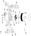
- a single-chamber sputter deposition apparatus 200 for forming such inorganic layers is illustrated schematically in Fig. 2 .
- the apparatus 200 includes a vacuum chamber 205 having a substrate stage 210 onto which one or more glass substrates 212 can be mounted, and a mask stage 220, which can be used to mount shadow masks 222 for patterned deposition of an inorganic layer onto a defined region of a substrate.
- the chamber 205 is equipped with a vacuum port 240 for controlling the interior pressure, as well as a water cooling port 250 and a gas inlet port 260.
- the vacuum chamber can be cryo-pumped (CTI-8200/Helix; MA, USA) and is capable of operating at pressures suitable for both evaporation processes ( ⁇ 10 -6 Torr) and RF sputter deposition processes ( ⁇ 10 -3 Torr).
- multiple evaporation fixtures 280 each having an optional corresponding shadow mask 222 for evaporating material onto a glass substrate 212 are connected via conductive leads 282 to a respective power supply 290.
- a starting material 200 to be evaporated can be placed into each fixture 280.
- Thickness monitors 286 can be integrated into a feedback control loop including a controller 293 and a control station 295 in order to affect control of the amount of material deposited.
- each of the evaporation fixtures 280 are outfitted with a pair of copper leads 282 to provide DC current at an operational power of about 80-180 Watts.
- the effective fixture resistance will generally be a function of its geometry, which will determine the precise current and wattage.
- An RF sputter gun 300 having a sputter target 310 is also provided for forming a layer of inorganic material (e.g., metal oxide, nitride, carbide or boride) on a glass substrate.
- the RF sputter gun 300 is connected to a control station 395 via an RF power supply 390 and feedback controller 393.
- a water-cooled cylindrical RF sputtering gun (Onyx-3TM, Angstrom Sciences, Pa) can be positioned within the chamber 105.
- Suitable RF deposition conditions include 50-150 W forward power ( ⁇ 1 W reflected power), which corresponds to a typical deposition rate of about ⁇ 5 ⁇ /second (Advanced Energy, Co, USA).
- the sputtering rate can vary between 0.1 and 10 angstroms per second, for example.
- the deposition temperature, processing pressure and/or deposition time utilized to form the layer of inorganic material may be controlled.
- the deposition time may be controlled to a time in the range from about 1 minute to about 600 minutes, from about 10 minutes to about 600 minutes, from about 30 minutes to about 500 minutes, from about 100 minutes to about 400 minutes, from about 200 minutes to about 300 minutes, and all ranges and sub-ranges therebetween.
- the pressure at which the layer of inorganic material is formed or the processing pressure may be controlled to between about 0. 1mTorr and 100 Torr, from about 0. 1mTorr to about 100 mTorr and all ranges and sub-ranges therebetween.
- the temperature at which the layer of inorganic material is formed may be controlled to a temperature less than about 300 °C.
- one, two or three of the processing conditions of deposition time, pressure and deposition temperature may be controlled.
- deposition temperature it is noted that in some embodiments, the deposition time does not need to be limited where the deposition temperature is maintained at less than about 300 °C. For example, at such temperatures, the deposition process may continue for several minutes to several hours depending on the type of deposition process utilized. For some sputtering processes, the deposition time may last several hours when the deposition temperature is controlled to less than about 300 °C. At these temperatures, the compressive stress generated in the glass substrate (and any corresponding central tension present in the central region of the glass substrate) is not significantly affected.
- Total deposition time includes the time at which the glass substrate is exposed to deposition temperatures, including in deposition recipes in which deposition is interrupted such that the glass substrate is no longer exposed to deposition temperatures (e.g., by removing the glass substrate from a deposition chamber or otherwise cooling the deposition chamber to temperatures below about 300 °C).
- the time during which the glass substrate is not exposed to deposition temperatures is not included in the total deposition time. It is believed that the adverse effect to the chemical strengthening of the glass substrate is due, at least in part, to the diffusion promoted within the glass substrate as a result of the elevated deposition temperatures.
- the elevated deposition temperatures increase ion mobility in the glass substrate and thus, can cause the larger ions present at the surface of the glass substrate to layer to migrate, thus adversely affecting the compressive stress in the surface of the glass substrate.
- the inorganic layer may comprise a metal oxide layer, a metal nitride layer, a metal carbide layer or a metal boride layer.
- Example metals for such an oxide, nitride, carbide or boride layer include boron, aluminum, silicon, titanium, vanadium, chromium, yttrium, zirconium, niobium, molybdenum, tin, hafnium, tantalum and tungsten.
- Non-limiting example inorganic layers include aluminum oxide and zirconium oxide layers.
- a thickness of the inorganic layer can range from 10 nm to 3 microns.
- the average inorganic layer thickness can be about 10, 20, 50, 100, 200, 300, 400, 500, 600, 700, 800, 900, 1000, 1500, 2000 nm, 2500 nm, 3000 nm and all ranges and sub-ranges therebetween.
- the inorganic layer can have a hardness that is greater than (e.g., at least 10% greater than) the hardness of the substrate.
- the inorganic layer hardness can be at least 10, 20, 30, 40 or 50% greater than the substrate hardness.
- An example inorganic layer can have a Berkovich indenter hardness of at least 9 GPa.
- the inorganic layer can be under a state of compressive stress. As mentioned herein, in some instances, the compressive stress of the inorganic layer is independent of the compressive stress of the underlying glass substrate and/or of the effects to the compressive stress of the underlying glass substrate due to the process utilized to form the inorganic layer.
- the properties of the inorganic layer may be altered depending on the temperature(s) at which it is formed or deposited on the glass substrate. For example, when layers such as the inorganic layer are deposited at high temperatures, impurities that may be found in such layers or in the precursor materials utilized to form the layers may be driven off. The higher temperature(s) may also cause any voids in the layer to fill, which can lead to a more dense film. This is because the atoms deposited onto the glass substrate to form the layer (e.g., the inorganic layer) have greater surface mobility and can move to fill in such voids.
- the atoms deposited onto the glass substrate to form the layer have less mobility and therefore do not as readily fill voids in the formed layer.
- the resulting layer formed at lower temperatures is therefore less dense.
- the resulting inorganic layer still imparts the requisite scratch resistance or other properties, while the glass substrate retains its strength due to chemical strengthening.
- the inorganic layer can be CTE-matched with the chemically-strengthened glass substrate.
- the inorganic layer has a coefficient of thermal expansion that differs from the coefficient of thermal expansion of the glass substrate by at most 10%, e.g., the CTE difference is less than 10, 5, 2 or 1%.
- a scratch-resistant glass substrate may possess an array of properties, which may include low weight, high impact resistance, and high optical transparency.
- the optical properties of the inorganic layer can be tailored to minimize scattering and absorption of light, which can result in a high optical-quality glass article.
- the inorganic layer can be optically clear (e.g., water clear) and optically transparent.
- the inorganic layer can have a refractive index within the visible spectrum of less than about 3, e.g., from about 1.4 to 2, and a reflectance within the visible spectrum of less than 40%, e.g., less than 40, 30, 20, 10 or 5%.
- the inorganic layer can transmit 95% or more of incident light, e.g., at least 95, 96, 97, 98 or 99%.
- the inorganic layer can be substantially free of scratches, including microductile scratches.
- the loading cycle applied during scratch-resistance testing typically gives rise to three different response regimes.
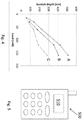
- the scratch pattern made on a glass surface as a function of applied load is shown schematically in Fig. 3 .
- Arrow A in Fig. 3 indicates the direction of scratching.
- the first regime is the micro-ductile regime (I), which corresponds to plastic deformation under the indenter 400 and the appearance of a permanent groove 410. In this first regime, sub-surface lateral cracks may also appear.
- a characteristic of the micro-ductile regime is the absence of damage or debris on either side of the groove 410.
- the second regime (II) which is encountered when the load increases, is called the micro-cracking regime.
- Chip and fragment 420 formations occur in the micro-cracking regime as a consequence of the intersection of lateral cracks with the surface. Radial (chevron) cracks 425 may also form in the micro-cracking regime. Such cracking can dramatically affect the optical transparency of the glass.
- the third regime (III) is termed the micro-abrasive regime, and is characterized by the formation of bulk debris 430.
- thin aluminum oxide layers were deposited via RF magnetron sputtering from an aluminum oxide target onto chemically-strengthened glass substrates.
- the substrate temperature was held between 100 and 300°C during the deposition and the final oxide layer thickness was about 200 nm.
- the deposition rate varied between 0.01 and 1 nm/sec.
- FIG. 4 A plot of scratch depth versus applied load is shown in Fig. 4 for (A) an un-chemically-strengthened glass substrate, (B) a chemically-strengthened glass substrate, and (C) a chemically-strengthened glass substrate having an inorganic layer formed over the tested surface of the substrate. Compared to the chemically-strengthened glass substrate without the inorganic protective layer, the addition of the inorganic protective layer reduced the scratch depth by as much as 25%.
- the formation of the inorganic layer of a surface of the glass substrate can reduce the scratch depth in such a sample (compared to an otherwise equivalent but unprotected glass substrate) by at least 10%, e.g., greater than 10, 20, 30, 40 or 50%.
- the glass article comprises a chemically-strengthened glass substrate and an inorganic, optically-transparent layer formed over a majority of one major surface of the substrate.
- the inorganic layer can substantially enhance the scratch resistance of the glass surface while maintaining the overall optical clarity of the article.
- Glass articles that may benefit from scratch resistance include military and civilian optics, including watch crystals, scanner windows at grocery stores, scanner windows on photocopiers, and LCD screen protectors, hard disk memory surfaces, piston rings in engines, machine tools, and other moving and sliding components.
- military and civilian optics including watch crystals, scanner windows at grocery stores, scanner windows on photocopiers, and LCD screen protectors, hard disk memory surfaces, piston rings in engines, machine tools, and other moving and sliding components.
- a mobile electronic device comprising a cover plate, at least a portion of which is transparent, is also disclosed.
- Such mobile electronic devices include, but are not limited to, mobile communication devices such as personal data assistants, mobile telephones, pagers, watches, radios, laptop computers and notebooks, and the like.
- a "cover plate” refers to a glass sheet or window that covers a visual display. At least a portion of the cover plate is transparent to allow viewing of the display.
- the cover plate may to some extent be resistant to shock, breakage, and scratching and finds application in those electronic devices where a window having high surface strength, hardness, and scratch resistance is desirable.
- the cover plate is touch sensitive.
- Mobile telephone 500 includes a cover plate 510 comprising a scratch-resistant, chemically-strengthened glass as described herein.
- cover plate 510 serves as a display window.
- a sheet of down-drawn glass can be cut to the desired shape and size.
- the glass sheet may be strengthened by ion exchange, and then provided with an inorganic, scratch-resistant layer over an exposed surface of the glass.
- the cover plate may then be joined to the body of the mobile electronic device using an adhesive or other means known in the art.
- a cover plate for a device such as, but not limited to, the mobile electronic devices described above as well as non-electronic watches and other like, is also provided.
- the cover plate may be formed from any of the glass compositions disclosed herein above.
- Ranges can be expressed herein as from “about” one particular value, and/or to “about” another particular value. When such a range is expressed, examples include from the one particular value and/or to the other particular value. Similarly, when values are expressed as approximations, by use of the antecedent "about,” it will be understood that the particular value forms another aspect. It will be further understood that the endpoints of each of the ranges are significant both in relation to the other endpoint, and independently of the other endpoint.
- Example 1 Four samples each were prepared according to Example 1 and Comparative Example 2.
- the four samples according to Example 1 were prepared by providing a chemically strengthened glass substrate having opposing major surfaces and depositing an inorganic layer on one surface comprising aluminum nitride via ion beam sputtering process.
- the resulting inorganic layer formed on each of the four samples according to Example 1 had a thickness of about 1.175 ⁇ m.
- the deposition temperature was maintained at about 160 °C and the pressure was maintained at 0. 588 mTorr.
- the inorganic layer was sputtered from a target in the presence of argon flowed at a rate of about 75 sccm, with DC power supplied at 3.9 kW.
- the ion beam was generated at a power in the range from about 0.224kW to about 0.196kW using a mixture of nitrogen and argon gases.
- Comparative Example 2 Four samples each of Comparative Example 2 were prepared by providing four chemically-strengthened glass substrates having the same compressive stress and compressive stress layer thicknesses as the chemically strengthened glass substrates utilized in the samples of Example 1.
- Example 1 and Comparative Example 2 were scratched at four different loads using a Berkovich indenter.
- the side of the glass substrate including the inorganic layer was scratched.
- the width and depth of the scratch on each of the samples were measured and are provided in Table 1.
- Table 1 Scratch loads and width and depth measurements.
- Example 1 Sample Width ( ⁇ m) Depth (nm) Width Reduction Depth Reduction Example 1 1 (160mN load) 4.42 145 12% 23% Comparative Example 2 1 (160mN load) 5.05 189 Example 1 2 (120 mN load) 3.71 130 22% 20% Comparative Example 2 2 (120 mN load) 4.74 163 Example 1 3 (60mN load) 2.45 65 26% 40% Comparative Example 2 3 (60mN load) 3.33 108 Example 1 4 (30mN load) 0.95 33 57% 45% Comparative Example 2 4 (30mN load) 2.21 60
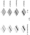
- Fig. 6 shows an atomic force microscopy (AFM) of the samples of Example 1 and Comparative Example 2, after each sample was scratched.
- AFM atomic force microscopy
- references herein refer to a component being “configured” or “adapted to” function in a particular way.
- such a component is “configured” or “adapted to” embody a particular property, or function in a particular manner, where such recitations are structural recitations as opposed to recitations of intended use.
- the references herein to the manner in which a component is “configured” or “adapted to” denotes an existing physical condition of the component and, as such, is to be taken as a definite recitation of the structural characteristics of the component.
Abstract
Description
- This application claims the benefit of priority under 35 U.S.C. § 119 of
U.S. Provisional Application Serial No. 61/709,334 filed on October 3, 2012 - The present disclosure relates generally to scratch-resistant glass articles, and more particularly to glass substrates having a scratch-resistant layer formed over a major surface of the substrate.
- Scratches are a concern for glass cover applications in hand held devices and other devices such as monitors and other displays. Scratches increase the scattering of light and can reduce the brightness and contrast of images and text that is presented on such screens. Further, in the device-off state, scratches can make the display look hazy, marred and unattractive. In particular for displays and handheld devices, scratch resistance can be an important attribute.
- Scratches can be characterized by their depth as well as their width. Deep scratches extend at least 2 microns into the surface of the material, and wide scratches are more than 2 microns wide. Due to the physical extent of the scratch, fragmentation or chipping typically accompanies deep and/or wide scratches. In brittle solids, though, such as glass substrates, the resistance to deep and wide scratches can be improved through optimization of glass chemistry, i.e., glass composition.
- On the other hand, scratches can also be shallow and/or narrow. Shallow scratches are characterized by a depth of less than 2 microns, and narrow scratches are characterized by a width of less than 2 microns. Scratches at these dimensional scales are sometimes described as "microductile" scratches. In displays and handheld devices, where a glass cover can be formed from an oxide glass, a large fraction of the scratches accumulated during use are believed to be microductile scratches. Though microductile scratches are not typically associated with large volumes of fragmented or chipped material, microductile scratches can adversely affect the optical properties of a glass cover. Further, in contrast to the larger, "heavy" scratches, microductile scratches are not easily prevented through modification of the glass chemistry.
- The formation of microductile scratches can be attenuated by adjusting the hardness of the surface that is being scratched. Harder surfaces typically are more resistant to microductile scratching. While oxide glasses that form the glass substrates used in many glass covers typically have hardness values in the range of 6 to 9 GPa, as disclosed herein, the propensity of microductile scratch formation can be dramatically decreased by forming a hard surface layer on the oxide glass where the surface layer has a hardness value greater than 9 GPa.
- In view of the foregoing, it would be desirable to provide a hard, scratch-resistant coating that can be applied to rigid glass covers that is economical, optically transparent and physically and chemically compatible with the underlying glass sheet.
- Disclosed herein are methods for forming a scratch-resistant glass article. An embodiment of the method comprises providing a chemically-strengthened glass substrate having opposing major surfaces, and while heating the glass substrate to a temperature less than 500°C, forming an inorganic, optically-transparent layer over a majority of a first major surface. By limiting the temperature of the substrate to less than 500°C or less than 300°C during formation of the inorganic layer, the stress distribution profile within the chemically-strengthened glass can be preserved.
- The inorganic layer can be formed using reactive or non-reactive sputtering, though other physical vapor deposition or chemical vapor deposition processes can be used. Suitable process times for forming the inorganic layer, which can range in total thickness from 10 nm to 3 microns, can range from 1 minute to several hours. The glass substrate can be substantially planar and can have a thickness ranging from about 100 microns to 5 mm.
- In embodiments the inorganic layer is a contiguous, uninterrupted layer formed over a major surface of the substrate. The inorganic layer may be formed in direct contact with the substrate or, alternatively, one or more layers such as stress-relief layers, anti-reflective layer or adhesion-promoting layers may be formed between the inorganic layer and the substrate.
- A scratch-resistant glass article formed using the disclosed methods comprises a chemically-strengthened glass substrate having opposing major surfaces, and an inorganic, optically-transparent layer formed over a majority of a first major surface of the substrate.
- The inorganic layer may comprise an oxide layer such as an aluminum oxide layer or a zirconium oxide layer, though other transition metal oxides may be used. Further, the inorganic layer may also comprise a metal nitride, a metal carbide and/or a metal boride. Example metals for an oxide, nitride, carbide or boride inorganic layer include boron, aluminum, silicon, titanium, vanadium, chromium, yttrium, zirconium, niobium, molybdenum, tin, hafnium, tantalum and tungsten.
- The inorganic layer can have a hardness that is greater than (e.g., at least 10% greater than) the hardness of the substrate. For example, the inorganic layer can have a Berkovich indenter hardness of at least 9 GPa. The inorganic layer can be under a state of compressive stress.
- The glass substrate can be used, for example, as cover glass in a variety of different devices, including touch screen and passive displays. As such, the inorganic layer can be optically clear (e.g., water clear) and transparent. In embodiments, the inorganic layer has a refractive index over the visible spectrum of less than about 3, e.g., from about 1.4 and 2, and a maximum reflectance over the visible spectrum of less than 40%. The inorganic layer can be substantially free of scratches, including microductile scratches.
- Additional features and advantages of the invention will be set forth in the detailed description which follows, and in part will be readily apparent to those skilled in the art from that description or recognized by practicing the invention as described herein, including the detailed description which follows, the claims, as well as the appended drawings.
- It is to be understood that both the foregoing general description and the following detailed description present embodiments of the invention, and are intended to provide an overview or framework for understanding the nature and character of the invention as it is claimed. The accompanying drawings are included to provide a further understanding of the invention, and are incorporated into and constitute a part of this specification. The drawings illustrate various embodiments of the invention and together with the description serve to explain the principles and operations of the invention.
-
-
Fig. 1 is a schematic of a scratch-resistant inorganic layer formed over a major surface of a glass substrate; -
Fig. 2 is a schematic diagram of a single chamber sputter tool for forming inorganic, scratch-resistant layers on glass substrates; -
Fig. 3 is a schematic showing scratch formation in a glass surface under monotonic loading cycle; -
Fig. 4 is a plot of scratch depth versus load for (A) an as-formed alkali aluminosilicate glass substrate, (B) a chemically-strengthened alkali aluminosilicate glass substrate, and (C) an aluminum oxide-coated, chemically-strengthened alkali aluminosilicate glass substrate; and -
Fig. 5 is a top view of a mobile electronic device having a cover plate formed of a scratch-resistant glass according to various embodiments. -
Fig. 6 illustrates the scratch depth and width reduction of glass substrates according to one or more embodiments in comparison to bare glass substrates. - A method for forming a scratch-resistant glass article comprises providing a chemically-strengthened glass substrate having opposing major surfaces, and forming an inorganic, optically-transparent layer over a majority of a first major surface. To avoid adversely affect the chemical strengthening of the substrate, the act of forming comprises heating the glass substrate to a maximum temperature of 500°C. The temperature of the substrate during the act of forming the inorganic layer can range from about -200°C to 500°C. In embodiments, the substrate temperature is maintained at a temperature between about room temperature and 500°C, e.g., at a temperature of less than 500°C or less than 300°C during the formation of the inorganic layer.
- The methods disclosed herein address the adverse effect of the chemical strengthening of the glass substrate. The adverse effect on the chemical strengthening of the glass substrate should be distinguished from any adverse or beneficial effect on the properties of the inorganic layer due to process conditions. In one or more embodiments, the adverse effect on the chemical strengthening of the glass substrate may include relaxation of the compressive stress generated in the glass substrate by a chemical strengthening process, as will be discussed in greater detail herein.
- A scratch-
resistant glass article 100 comprising an inorganic layer 110 formed over a glass substrate 120 is shown inFig. 1 . - The glass substrate itself may be provided using a variety of different processes. For instance, example glass substrate forming methods include float processes and down-draw processes such as fusion draw and slot draw.
- In the float glass method, a sheet of glass that may be characterized by smooth surfaces and uniform thickness is made by floating molten glass on a bed of molten metal, typically tin. In an example process, molten glass that is fed onto the surface of the molten tin bed forms a floating ribbon. As the glass ribbon flows along the tin bath, the temperature is gradually decreased until a solid glass sheet can be lifted from the tin onto rollers. Once off the bath, the glass sheet can be cooled further and annealed to reduce internal stress.
- Down-draw processes produce glass sheets having a uniform thickness that possess surfaces that are relatively pristine. Because the strength of the glass surface is controlled by the amount and size of surface flaws, a pristine surface that has had minimal contact has a higher initial strength. When this high strength glass is then chemically-strengthened, the resultant strength can be higher than that of a surface that has been a lapped and polished. Down-drawn glass may be drawn to a thickness of less than about 2 mm. In addition, down drawn glass has a very flat, smooth surface that can be used in its final application without costly grinding and polishing.
- The fusion draw process, for example, uses a drawing tank that has a channel for accepting molten glass raw material. The channel has weirs that are open at the top along the length of the channel on both sides of the channel. When the channel fills with molten material, the molten glass overflows the weirs. Due to gravity, the molten glass flows down the outside surfaces of the drawing tank. These outside surfaces extend down and inwardly so that they join at an edge below the drawing tank. The two flowing glass surfaces join at this edge to fuse and form a single flowing sheet. The fusion draw method offers the advantage that, because the two glass films flowing over the channel fuse together, neither outside surface of the resulting glass sheet comes in contact with any part of the apparatus. Thus, the surface properties of the fusion drawn glass sheet are not affected by such contact.
- The slot draw method is distinct from the fusion draw method. Here the molten raw material glass is provided to a drawing tank. The bottom of the drawing tank has an open slot with a nozzle that extends the length of the slot. The molten glass flows through the slot/nozzle and is drawn downward as a continuous sheet and into an annealing region. The slot draw process can provide a thinner sheet than the fusion draw process because only a single sheet is drawn through the slot, rather than two sheets being fused together.
- The chemically-strengthened glass substrate, in some embodiments, may be batched with 0-2 mol.% of at least one fining agent selected from a group that includes Na2SO4, NaCl, NaF, NaBr, K2SO4, KCl, KF, KBr, and SnO2.
- Once formed, glass substrates may be chemically strengthened by an ion exchange process. In this process, typically by immersion of the glass substrate into a molten salt bath for a predetermined period of time, ions at or near the surface of the glass are exchanged for larger metal ions from the salt bath. In one embodiment, the temperature of the molten salt bath is about 430°C and the predetermined time period is about eight hours. The incorporation of the larger ions into the glass strengthens the substrate by creating a compressive stress in a near surface region. A corresponding tensile stress is induced within a central region of the glass to balance the compressive stress.
- In one example embodiment, sodium ions in the chemically-strengthened glass can be replaced by potassium ions from the molten bath, though other alkali metal ions having larger atomic radii, such as rubidium or cesium, can replace smaller alkali metal ions in the glass. According to particular embodiments, smaller alkali metal ions in the glass can be replaced by Ag+ ions. Similarly, other alkali metal salts such as, but not limited to, sulfates, halides, and the like may be used in the ion exchange process.
- The replacement of smaller ions by larger ions at a temperature below that at which the glass network can relax produces a distribution of ions across the surface of the glass that results in a stress profile. The larger volume of the incoming ion produces a compressive stress (CS) on the surface and tension (central tension, or CT) in the center of the glass. The compressive stress is related to the central tension by the following relationship:

- In one embodiment, a chemically-strengthened glass sheet can have a surface compressive stress of at least 300 MPa, e.g., at least 400, 450, 500, 550, 600, 650, 700, 750 or 800 MPa, a depth of layer at least about 20 µm (e.g., at least about 20, 25, 30, 35, 40, 45, or 50 µm) and/or a central tension greater than 40 MPa (e.g., greater than 40, 45, or 50 MPa) but less than 100 MPa (e.g., less than 100, 95, 90, 85, 80, 75, 70, 65, 60, or 55 MPa).
- Example ion-exchangeable glasses that may be used as the glass substrate are alkali aluminosilicate glasses or alkali aluminoborosilicate glasses, though other glass compositions are contemplated. As used herein, "ion exchangeable" means that a glass is capable of exchanging cations located at or near the surface of the glass with cations of the same valence that are either larger or smaller in size. One example glass composition comprises SiO2, B2O3 and Na2O, where (SiO2 + B2O3) ≥ 66 mol.%, and Na2O ≥ 9 mol.%. In an embodiment, the glass substrate includes at least 6 wt.% aluminum oxide. In a further embodiment, a glass substrate includes one or more alkaline earth oxides, such that a content of alkaline earth oxides is at least 5 wt.%. Suitable glass compositions, in some embodiments, further comprise at least one of K2O, MgO, and CaO. In a particular embodiment, the glass substrate can comprise 61-75 mol.% SiO2; 7-15 mol.% Al2O3; 0-12 mol.% B2O3; 9-21 mol.% Na2O; 0-4 mol.% K2O; 0-7 mol.% MgO; and 0-3 mol.% CaO.
- A further example glass composition suitable for the glass substrate comprises: 60-70 mol.% SiO2; 6-14 mol.% Al2O3; 0-15 mol.% B2O3; 0-15 mol.% Li2O; 0-20 mol.% Na2O; 0-10 mol.% K2O; 0-8 mol.% MgO; 0-10 mol.% CaO; 0-5 mol.% ZrO2; 0-1 mol.% SnO2; 0-1 mol.% CeO2; less than 50 ppm As2O3; and less than 50 ppm Sb2O3; where 12 mol.% ≤ (Li2O + Na2O + K2O) ≤ 20 mol.% and 0 mol.% ≤ (MgO + CaO) ≤ 10 mol.%.
- A still further example glass composition comprises: 63.5-66.5 mol.% SiO2; 8-12 mol.% Al2O3; 0-3 mol.% B2O3; 0-5 mol.% Li2O; 8-18 mol.% Na2O; 0-5 mol.% K2O; 1-7 mol.% MgO; 0-2.5 mol.% CaO; 0-3 mol.% ZrO2; 0.05-0.25 mol.% SnO2; 0.05-0.5 mol.% CeO2; less than 50 ppm AS2O3; and less than 50 ppm Sb2O3; where 14 mol.% ≤ (Li2O + Na2O + K2O) ≤ 18 mol.% and 2 mol.% ≤ (MgO + CaO) ≤ 7 mol.%.
- In a particular embodiment, an alkali aluminosilicate glass comprises alumina, at least one alkali metal and, in some embodiments, greater than 50 mol.% SiO2, in other embodiments at least 58 mol.% SiO2, and in still other embodiments at least 60 mol.% SiO2, wherein the ratio


- In another embodiment, an alkali aluminosilicate glass comprises, consists essentially of, or consists of: 61-75 mol.% SiO2; 7-15 mol.% Al2O3; 0-12 mol.% B2O3; 9-21 mol.% Na2O; 0-4 mol.% K2O; 0-7 mol.% MgO; and 0-3 mol.% CaO.
- In yet another embodiment, an alkali aluminosilicate glass substrate comprises, consists essentially of, or consists of: 60-70 mol.% SiO2; 6-14 mol.% Al2O3; 0-15 mol.% B2O3; 0-15 mol.% Li2O; 0-20 mol.% Na2O; 0-10 mol.% K2O; 0-8 mol.% MgO; 0-10 mol.% CaO; 0-5 mol.% ZrO2; 0-1 mol.% SnO2; 0-1 mol.% CeO2; less than 50 ppm As2O3; and less than 50 ppm Sb2O3; wherein 12 mol.% ≤ Li2O + Na2O + K2O ≤ 20 mol.% and 0 mol.% ≤ MgO + CaO ≤ 10 mol.%.
- In still another embodiment, an alkali aluminosilicate glass comprises, consists essentially of, or consists of: 64-68 mol.% SiO2; 12-16 mol.% Na2O; 8-12 mol.% Al2O3; 0-3 mol.% B2O3; 2-5 mol.% K2O; 4-6 mol.% MgO; and 0-5 mol.% CaO, wherein: 66 mol.% ≤ SiO2 + B2O3 + CaO ≤ 69 mol.%; Na2O + K2O + B2O3 + MgO + CaO + SrO > 10 mol.%; 5 mol.% ≤ MgO + CaO + SrO ≤ 8 mol.%; (Na2O + B2O3) - Al2O3 ≤ 2 mol.%; 2 mol.% ≤ Na2O - Al2O3 ≤ 6 mol.%; and 4 mol.% ≤ (Na2O + K2O) - Al2O3 ≤ 10 mol.%.
- The glass substrate can have a thickness ranging from about 100 microns to 5 mm. Example substrate thicknesses range from 100 microns to 500 microns, e.g., 100, 200, 300, 400 or 500 microns. Further example substrate thicknesses range from 500 microns to 1000 microns, e.g., 500, 600, 700, 800, 900 or 1000 microns. The glass substrate may have a thickness greater than 1 mm, e.g., about 2, 3, 4, or 5 mm.
- The inorganic layers can be formed by chemical vapor deposition (e.g., plasma enhanced chemical vapor deposition), physical vapor deposition (e.g., sputter deposition or laser ablation) or thermal evaporation of a suitable starting material directly onto a glass substrate. Sputtering processes may include reactive sputtering or non-reactive sputtering. A single-chamber
sputter deposition apparatus 200 for forming such inorganic layers is illustrated schematically inFig. 2 . - The
apparatus 200 includes avacuum chamber 205 having asubstrate stage 210 onto which one ormore glass substrates 212 can be mounted, and amask stage 220, which can be used to mountshadow masks 222 for patterned deposition of an inorganic layer onto a defined region of a substrate. Thechamber 205 is equipped with avacuum port 240 for controlling the interior pressure, as well as awater cooling port 250 and agas inlet port 260. The vacuum chamber can be cryo-pumped (CTI-8200/Helix; MA, USA) and is capable of operating at pressures suitable for both evaporation processes (∼ 10-6 Torr) and RF sputter deposition processes (∼ 10-3 Torr). - As shown in
Fig. 2 ,multiple evaporation fixtures 280, each having an optionalcorresponding shadow mask 222 for evaporating material onto aglass substrate 212 are connected via conductive leads 282 to arespective power supply 290. A startingmaterial 200 to be evaporated can be placed into eachfixture 280. Thickness monitors 286 can be integrated into a feedback control loop including acontroller 293 and acontrol station 295 in order to affect control of the amount of material deposited. - In an example system, each of the
evaporation fixtures 280 are outfitted with a pair of copper leads 282 to provide DC current at an operational power of about 80-180 Watts. The effective fixture resistance will generally be a function of its geometry, which will determine the precise current and wattage. - An
RF sputter gun 300 having asputter target 310 is also provided for forming a layer of inorganic material (e.g., metal oxide, nitride, carbide or boride) on a glass substrate. TheRF sputter gun 300 is connected to acontrol station 395 via anRF power supply 390 andfeedback controller 393. For sputtering inorganic layers, a water-cooled cylindrical RF sputtering gun (Onyx-3™, Angstrom Sciences, Pa) can be positioned within the chamber 105. Suitable RF deposition conditions include 50-150 W forward power (< 1 W reflected power), which corresponds to a typical deposition rate of about ∼ 5 Å/second (Advanced Energy, Co, USA). In embodiments, the sputtering rate can vary between 0.1 and 10 angstroms per second, for example. - To avoid adversely affect the chemical strengthening of the glass substrate, the deposition temperature, processing pressure and/or deposition time utilized to form the layer of inorganic material may be controlled. In one or more embodiments, the deposition time may be controlled to a time in the range from about 1 minute to about 600 minutes, from about 10 minutes to about 600 minutes, from about 30 minutes to about 500 minutes, from about 100 minutes to about 400 minutes, from about 200 minutes to about 300 minutes, and all ranges and sub-ranges therebetween. In one variant, the pressure at which the layer of inorganic material is formed or the processing pressure may be controlled to between about 0. 1mTorr and 100 Torr, from about 0. 1mTorr to about 100 mTorr and all ranges and sub-ranges therebetween. In another variant, the temperature at which the layer of inorganic material is formed may be controlled to a temperature less than about 300 °C.
- In one or more embodiments, one, two or three of the processing conditions of deposition time, pressure and deposition temperature may be controlled. With respect to deposition temperature, it is noted that in some embodiments, the deposition time does not need to be limited where the deposition temperature is maintained at less than about 300 °C. For example, at such temperatures, the deposition process may continue for several minutes to several hours depending on the type of deposition process utilized. For some sputtering processes, the deposition time may last several hours when the deposition temperature is controlled to less than about 300 °C. At these temperatures, the compressive stress generated in the glass substrate (and any corresponding central tension present in the central region of the glass substrate) is not significantly affected.
- When deposition temperatures of 300 °C and above (e.g., 400 °C and above or even 500 °C and above) are utilized, the deposition time may need to be limited to a few minutes or even a few seconds before the chemical strengthening of the glass substrate begins to be adversely affected. The adverse effect may be seen even when the total deposition time is a few minutes or a few seconds. Total deposition time includes the time at which the glass substrate is exposed to deposition temperatures, including in deposition recipes in which deposition is interrupted such that the glass substrate is no longer exposed to deposition temperatures (e.g., by removing the glass substrate from a deposition chamber or otherwise cooling the deposition chamber to temperatures below about 300 °C). The time during which the glass substrate is not exposed to deposition temperatures is not included in the total deposition time. It is believed that the adverse effect to the chemical strengthening of the glass substrate is due, at least in part, to the diffusion promoted within the glass substrate as a result of the elevated deposition temperatures. The elevated deposition temperatures increase ion mobility in the glass substrate and thus, can cause the larger ions present at the surface of the glass substrate to layer to migrate, thus adversely affecting the compressive stress in the surface of the glass substrate.
- The inorganic layer may comprise a metal oxide layer, a metal nitride layer, a metal carbide layer or a metal boride layer. Example metals for such an oxide, nitride, carbide or boride layer include boron, aluminum, silicon, titanium, vanadium, chromium, yttrium, zirconium, niobium, molybdenum, tin, hafnium, tantalum and tungsten. Non-limiting example inorganic layers include aluminum oxide and zirconium oxide layers.
- A thickness of the inorganic layer can range from 10 nm to 3 microns. For example, the average inorganic layer thickness can be about 10, 20, 50, 100, 200, 300, 400, 500, 600, 700, 800, 900, 1000, 1500, 2000 nm, 2500 nm, 3000 nm and all ranges and sub-ranges therebetween.
- The inorganic layer can have a hardness that is greater than (e.g., at least 10% greater than) the hardness of the substrate. For instance, the inorganic layer hardness can be at least 10, 20, 30, 40 or 50% greater than the substrate hardness. An example inorganic layer can have a Berkovich indenter hardness of at least 9 GPa. The inorganic layer can be under a state of compressive stress. As mentioned herein, in some instances, the compressive stress of the inorganic layer is independent of the compressive stress of the underlying glass substrate and/or of the effects to the compressive stress of the underlying glass substrate due to the process utilized to form the inorganic layer.
- The properties of the inorganic layer may be altered depending on the temperature(s) at which it is formed or deposited on the glass substrate. For example, when layers such as the inorganic layer are deposited at high temperatures, impurities that may be found in such layers or in the precursor materials utilized to form the layers may be driven off. The higher temperature(s) may also cause any voids in the layer to fill, which can lead to a more dense film. This is because the atoms deposited onto the glass substrate to form the layer (e.g., the inorganic layer) have greater surface mobility and can move to fill in such voids. On the other hand, when the surface of the glass substrate is cold or unheated, the atoms deposited onto the glass substrate to form the layer (e.g., the inorganic layer) have less mobility and therefore do not as readily fill voids in the formed layer. The resulting layer formed at lower temperatures is therefore less dense. As will be discussed, although lower temperatures are utilized to form the inorganic layer of the embodiments described herein, the resulting inorganic layer still imparts the requisite scratch resistance or other properties, while the glass substrate retains its strength due to chemical strengthening.
- The inorganic layer can be CTE-matched with the chemically-strengthened glass substrate. In embodiments, the inorganic layer has a coefficient of thermal expansion that differs from the coefficient of thermal expansion of the glass substrate by at most 10%, e.g., the CTE difference is less than 10, 5, 2 or 1%.
- According to various embodiments, a scratch-resistant glass substrate may possess an array of properties, which may include low weight, high impact resistance, and high optical transparency.
- The optical properties of the inorganic layer can be tailored to minimize scattering and absorption of light, which can result in a high optical-quality glass article. In applications where the glass substrate is used as display cover glass, the inorganic layer can be optically clear (e.g., water clear) and optically transparent. For example, the inorganic layer can have a refractive index within the visible spectrum of less than about 3, e.g., from about 1.4 to 2, and a reflectance within the visible spectrum of less than 40%, e.g., less than 40, 30, 20, 10 or 5%. For instance, the inorganic layer can transmit 95% or more of incident light, e.g., at least 95, 96, 97, 98 or 99%. The inorganic layer can be substantially free of scratches, including microductile scratches.
- The loading cycle applied during scratch-resistance testing typically gives rise to three different response regimes. The scratch pattern made on a glass surface as a function of applied load is shown schematically in
Fig. 3 . Arrow A inFig. 3 indicates the direction of scratching. The first regime is the micro-ductile regime (I), which corresponds to plastic deformation under theindenter 400 and the appearance of apermanent groove 410. In this first regime, sub-surface lateral cracks may also appear. A characteristic of the micro-ductile regime is the absence of damage or debris on either side of thegroove 410. The second regime (II), which is encountered when the load increases, is called the micro-cracking regime. Chip and fragment 420 formations occur in the micro-cracking regime as a consequence of the intersection of lateral cracks with the surface. Radial (chevron) cracks 425 may also form in the micro-cracking regime. Such cracking can dramatically affect the optical transparency of the glass. The third regime (III) is termed the micro-abrasive regime, and is characterized by the formation ofbulk debris 430. - In experiments with oxide coatings, for example, a marked improvement in the scratch resistance toward microductile scratches was achieved for inorganic layer-coated chemically-strengthened glass substrates in comparison with non-chemically-strengthened and chemically-strengthened glass of the same base composition.
- In one set of experiments, thin aluminum oxide layers were deposited via RF magnetron sputtering from an aluminum oxide target onto chemically-strengthened glass substrates. The substrate temperature was held between 100 and 300°C during the deposition and the final oxide layer thickness was about 200 nm. The deposition rate varied between 0.01 and 1 nm/sec.
- An increase in scratch resistance was correlated to a reduction in the scratch depth for the protected glass substrate. As measured using a diamond-tipped Berkovich indenter, the scratch depth for the glass substrate having the inorganic protective layer was significantly reduced. A plot of scratch depth versus applied load is shown in
Fig. 4 for (A) an un-chemically-strengthened glass substrate, (B) a chemically-strengthened glass substrate, and (C) a chemically-strengthened glass substrate having an inorganic layer formed over the tested surface of the substrate. Compared to the chemically-strengthened glass substrate without the inorganic protective layer, the addition of the inorganic protective layer reduced the scratch depth by as much as 25%. By way of example, the formation of the inorganic layer of a surface of the glass substrate can reduce the scratch depth in such a sample (compared to an otherwise equivalent but unprotected glass substrate) by at least 10%, e.g., greater than 10, 20, 30, 40 or 50%. - In addition to the disclosed method, also disclosed is a scratch-resistant glass article made using the method. The glass article comprises a chemically-strengthened glass substrate and an inorganic, optically-transparent layer formed over a majority of one major surface of the substrate. The inorganic layer can substantially enhance the scratch resistance of the glass surface while maintaining the overall optical clarity of the article.
- Technologies that incorporate glass articles that may benefit from scratch resistance include military and civilian optics, including watch crystals, scanner windows at grocery stores, scanner windows on photocopiers, and LCD screen protectors, hard disk memory surfaces, piston rings in engines, machine tools, and other moving and sliding components.
- A mobile electronic device comprising a cover plate, at least a portion of which is transparent, is also disclosed. Such mobile electronic devices include, but are not limited to, mobile communication devices such as personal data assistants, mobile telephones, pagers, watches, radios, laptop computers and notebooks, and the like. As used herein, a "cover plate" refers to a glass sheet or window that covers a visual display. At least a portion of the cover plate is transparent to allow viewing of the display. The cover plate may to some extent be resistant to shock, breakage, and scratching and finds application in those electronic devices where a window having high surface strength, hardness, and scratch resistance is desirable. In one embodiment, the cover plate is touch sensitive.
- A schematic representation of a top view of a mobile telephone is shown in
Fig. 5 .Mobile telephone 500 includes acover plate 510 comprising a scratch-resistant, chemically-strengthened glass as described herein. Inmobile telephone 500,cover plate 510 serves as a display window. During formation of the cover plate, a sheet of down-drawn glass can be cut to the desired shape and size. Before or after sizing the cover plate, the glass sheet may be strengthened by ion exchange, and then provided with an inorganic, scratch-resistant layer over an exposed surface of the glass. The cover plate may then be joined to the body of the mobile electronic device using an adhesive or other means known in the art. - A cover plate for a device such as, but not limited to, the mobile electronic devices described above as well as non-electronic watches and other like, is also provided. The cover plate may be formed from any of the glass compositions disclosed herein above.
- As used herein, the singular forms "a," "an" and "the" include plural referents unless the context clearly dictates otherwise. Thus, for example, reference to a "layer" includes examples having two or more such "layers" unless the context clearly indicates otherwise.
- Ranges can be expressed herein as from "about" one particular value, and/or to "about" another particular value. When such a range is expressed, examples include from the one particular value and/or to the other particular value. Similarly, when values are expressed as approximations, by use of the antecedent "about," it will be understood that the particular value forms another aspect. It will be further understood that the endpoints of each of the ranges are significant both in relation to the other endpoint, and independently of the other endpoint.
- Unless otherwise expressly stated, it is in no way intended that any method set forth herein be construed as requiring that its steps be performed in a specific order. Accordingly, where a method claim does not actually recite an order to be followed by its steps or it is not otherwise specifically stated in the claims or descriptions that the steps are to be limited to a specific order, it is no way intended that any particular order be inferred.
- Various embodiments will be further clarified by the following examples.
- Four samples each were prepared according to Example 1 and Comparative Example 2. The four samples according to Example 1 were prepared by providing a chemically strengthened glass substrate having opposing major surfaces and depositing an inorganic layer on one surface comprising aluminum nitride via ion beam sputtering process. The resulting inorganic layer formed on each of the four samples according to Example 1 had a thickness of about 1.175µm. The deposition temperature was maintained at about 160 °C and the pressure was maintained at 0. 588 mTorr.
- The inorganic layer was sputtered from a target in the presence of argon flowed at a rate of about 75 sccm, with DC power supplied at 3.9 kW. The ion beam was generated at a power in the range from about 0.224kW to about 0.196kW using a mixture of nitrogen and argon gases.
- Four samples each of Comparative Example 2 were prepared by providing four chemically-strengthened glass substrates having the same compressive stress and compressive stress layer thicknesses as the chemically strengthened glass substrates utilized in the samples of Example 1.
- Each of the samples of Example 1 and Comparative Example 2 were scratched at four different loads using a Berkovich indenter. For the samples of Example 1, the side of the glass substrate including the inorganic layer was scratched. The width and depth of the scratch on each of the samples were measured and are provided in Table 1.
Table 1: Scratch loads and width and depth measurements. Sample Width (µm) Depth (nm) Width Reduction Depth Reduction Example 1 1 (160mN load) 4.42 145 12% 23% Comparative Example 2 1 (160mN load) 5.05 189 Example 1 2 (120 mN load) 3.71 130 22% 20% Comparative Example 2 2 (120 mN load) 4.74 163 Example 1 3 (60mN load) 2.45 65 26% 40% Comparative Example 2 3 (60mN load) 3.33 108 Example 1 4 (30mN load) 0.95 33 57% 45% Comparative Example 2 4 (30mN load) 2.21 60 -
Fig. 6 shows an atomic force microscopy (AFM) of the samples of Example 1 and Comparative Example 2, after each sample was scratched. As can be seen, there is significant reduction in scratch depth and width in the samples that included in the inorganic layer formed on the glass substrate, even with such layer was formed at temperatures below about 300 °C. The chemical strengthening of the glass substrates according to Example 1 was also maintained or, in other words, was not adversely affected. - It is also noted that recitations herein refer to a component being "configured" or "adapted to" function in a particular way. In this respect, such a component is "configured" or "adapted to" embody a particular property, or function in a particular manner, where such recitations are structural recitations as opposed to recitations of intended use. More specifically, the references herein to the manner in which a component is "configured" or "adapted to" denotes an existing physical condition of the component and, as such, is to be taken as a definite recitation of the structural characteristics of the component.
- While various features, elements or steps of particular embodiments may be disclosed using the transitional phrase "comprising," it is to be understood that alternative embodiments, including those that may be described using the transitional phrases "consisting" or "consisting essentially of," are implied. Thus, for example, implied alternative embodiments to a glass substrate that comprises a glass material include embodiments where a glass substrate consists of a glass material and embodiments where a glass substrate consists essentially of a glass material.
It will be apparent to those skilled in the art that various modifications and variations can be made to the present disclosure without departing from the spirit and scope of the invention. Since modifications combinations, sub-combinations and variations of the disclosed embodiments incorporating the spirit and substance of the invention may occur to persons skilled in the art, the invention should be construed to include everything within the scope of the appended claims and their equivalents. - Embodiments of the invention include the following:
- [1] A method for forming a scratch-resistant glass article comprising:
- providing a glass substrate having opposing major surfaces; and
- forming an inorganic, optically-transparent layer over a majority of a first major surface, wherein the forming comprises heating the glass substrate to a temperature of less than 500°C and the glass substrate comprises chemically-strengthened glass.
- [2] The method according to [1], wherein the forming comprises reactive or non-reactive sputtering, e-beam evaporation, chemical vapor deposition or plasma enhanced chemical vapor deposition.
- [3] The method according to [1], wherein the forming comprises heating the glass substrate to a temperature less than about 300°C.
- [4] The method according to [1], wherein the inorganic layer is formed using a deposition time of between about 1 and 600 min.
- [5] The method according to [1], wherein the inorganic layer is formed using a processing pressure of between about 0.1mTorr and 100 Torr.
- [6] The method according to [1], wherein the inorganic layer has a thickness ranging from about 10 nm to 3 microns.
- [7] The method according to [1], wherein the inorganic layer is a contiguous layer.
- [8] The method according to [1], wherein the inorganic layer is formed in direct physical contact with the glass substrate.
- [9] The method according to [1], wherein one or more of an adhesion-promoting layer, anti-reflective layer and a stress-reduction layer are formed between the glass substrate and the inorganic layer.
- [10] The method according to [1], wherein the glass substrate has a thickness ranging from about 100 microns to 5 mm.
- [11] A scratch-resistant glass article, comprising
a glass substrate having opposing major surfaces; and
a low-temperature-deposited inorganic, optically-transparent layer formed over a majority of a first major surface, wherein the glass substrate comprises chemically-strengthened glass,
wherein the scratch-resistant glass article exhibits a scratch depth reduction, when scratched using a Berkovich indenter and a load of up to about 160mN, of at least 20%, when compared to a glass substrate without the low-temperature-deposited inorganic, optically-transparent layer provided over a majority of a first major surface. - [12] The scratch-resistant glass article of [11], further exhibiting a scratch width reduction, when scratched using a Berkovich indenter and a load of up to about 160mN, of at least 20%, when compared to a glass substrate without the low-temperature-deposited inorganic, optically-transparent layer provided over a majority of a first major surface.
- [13] The article according to [11], wherein the inorganic layer comprises a metal oxide, a metal nitride, a metal carbide, a metal boride, or a combination thereof.
- [14] The article according to [13], wherein the metal is selected from the group consisting of B, Al, Si, Ti, V, Cr, Y, Zr, Nb, Mo, Sn, Hf, Ta and W.
- [15] The article according to [11], wherein the inorganic layer has a Berkovich indenter hardness of at least 9 GPa.
- [16] The article according to [11], wherein the inorganic layer has a hardness that is at least 10 % greater than a hardness of the glass substrate.
- [17] The article according to [11], wherein the inorganic layer has a thickness ranging from about 10 nm to 3 microns.
- [18] The article according to [11], wherein the inorganic layer is a contiguous layer.
- [19] The article according to [11], wherein the inorganic layer is formed in direct physical contact with the glass substrate.
- [20] The article according to [11], wherein one or more of an anti-reflective layer and a stress-reduction layer are formed between the glass substrate and the inorganic layer.
- [21] The article according to [11], wherein the glass substrate has a thickness ranging from about 100 microns to 5 mm.
- [22] The article according to [11], wherein the first major surface is substantially planar.
- [23] The article according to [11], wherein the inorganic layer is water clear.
- [24] The article according to [11], wherein the inorganic layer has a refractive index of less than about 3 at visible wavelengths.
- [25] The article according to [11], wherein the inorganic layer has a refractive index between about 1.4 and 2 at visible wavelengths.
- [26] The article according to [11], wherein the inorganic layer has a reflectance of less than about 40% at visible wavelengths.
- [27] The article according to [11], wherein the inorganic layer is under a state of compressive stress.
- [28] The article according to [11], where the inorganic layer is substantially free of microductile scratches.
Claims (15)
- A scratch-resistant glass article, comprisinga glass substrate having opposing major surfaces; anda low-temperature-deposited inorganic, optically-transparent layer formed over a majority of a first major surface, wherein the glass substrate comprises chemically-strengthened glass,wherein the scratch-resistant glass article exhibits a scratch depth reduction, when scratched using a Berkovich indenter and a load of up to about 160mN, of at least 20%, when compared to a glass substrate without the low-temperature-deposited inorganic, optically-transparent layer provided over a majority of a first major surface.
- The scratch-resistant glass article of claim 1, further exhibiting a scratch width reduction, when scratched using a Berkovich indenter and a load of up to about 160mN, of at least 20%, when compared to a glass substrate without the low-temperature-deposited inorganic, optically-transparent layer provided over a majority of a first major surface.
- The scratch-resistant glass article according to claim 1 or claim 2, wherein the inorganic layer comprises a metal oxide, a metal nitride, a metal carbide, a metal boride, or a combination thereof.
- The scratch-resistant glass article according to claim 3, wherein the metal is selected from the group consisting of B, Al, Si, Ti, V, Cr, Y, Zr, Nb, Mo, Sn, Hf, Ta and W.
- The scratch-resistant glass article according to any of claims 1 to 4, wherein the inorganic layer has a Berkovich indenter hardness of at least 9 GPa.
- The scratch-resistant glass article according to any of claims 1 to 5, wherein the inorganic layer has a hardness that is at least 10 % greater than a hardness of the glass substrate.
- The scratch-resistant glass article according to any of claims 1 to 6, wherein the inorganic layer has a thickness ranging from about 10 nm to 3 microns.
- The scratch-resistant glass article according to any of claims 1 to 7, wherein the inorganic layer is a contiguous layer.
- The scratch-resistant glass article according to any of claims 1 to 8, wherein the inorganic layer is formed in direct physical contact with the glass substrate.
- The scratch-resistant glass article according to any of claims 1 to 8, wherein one or more of an anti-reflective layer and a stress-reduction layer are formed between the glass substrate and the inorganic layer.
- The scratch-resistant glass article according to any of claims 1 to 10, wherein the glass substrate has a thickness ranging from about 100 microns to 5 mm.
- The scratch-resistant glass article according to any of claims 1 to 11, wherein the first major surface is substantially planar.
- The scratch-resistant glass article according to any of claims 1 to 12, wherein the inorganic layer has a refractive index of less than about 3 at visible wavelengths.
- The scratch-resistant glass article according to claim 13, wherein the inorganic layer has a refractive index between about 1.4 and 2 at visible wavelengths.
- The scratch-resistant glass article according to any of claims 1 to 14, wherein the inorganic layer has a reflectance of less than about 40% at visible wavelengths.
Applications Claiming Priority (3)
| Application Number | Priority Date | Filing Date | Title |
|---|---|---|---|
| US201261709334P | 2012-10-03 | 2012-10-03 | |
| EP13776901.4A EP2903825B1 (en) | 2012-10-03 | 2013-10-01 | Physical vapor deposited layers for protection of glass surfaces |
| PCT/US2013/062825 WO2014055489A1 (en) | 2012-10-03 | 2013-10-01 | Physical vapor deposited layers for protection of glass surfaces |
Related Parent Applications (2)
| Application Number | Title | Priority Date | Filing Date |
|---|---|---|---|
| EP13776901.4A Division-Into EP2903825B1 (en) | 2012-10-03 | 2013-10-01 | Physical vapor deposited layers for protection of glass surfaces |
| EP13776901.4A Division EP2903825B1 (en) | 2012-10-03 | 2013-10-01 | Physical vapor deposited layers for protection of glass surfaces |
Publications (1)
| Publication Number | Publication Date |
|---|---|
| EP3919271A1 true EP3919271A1 (en) | 2021-12-08 |
Family
ID=49356515
Family Applications (2)
| Application Number | Title | Priority Date | Filing Date |
|---|---|---|---|
| EP13776901.4A Active EP2903825B1 (en) | 2012-10-03 | 2013-10-01 | Physical vapor deposited layers for protection of glass surfaces |
| EP21177942.6A Pending EP3919271A1 (en) | 2012-10-03 | 2013-10-01 | Physical vapor deposited layers for protection of glass surfaces |
Family Applications Before (1)
| Application Number | Title | Priority Date | Filing Date |
|---|---|---|---|
| EP13776901.4A Active EP2903825B1 (en) | 2012-10-03 | 2013-10-01 | Physical vapor deposited layers for protection of glass surfaces |
Country Status (7)
| Country | Link |
|---|---|
| US (2) | US9751799B2 (en) |
| EP (2) | EP2903825B1 (en) |
| JP (2) | JP6525878B2 (en) |
| KR (2) | KR20190119188A (en) |
| CN (1) | CN104736339B (en) |
| TW (1) | TWI606986B (en) |
| WO (1) | WO2014055489A1 (en) |
Families Citing this family (24)
| Publication number | Priority date | Publication date | Assignee | Title |
|---|---|---|---|---|
| US20130127202A1 (en) * | 2011-11-23 | 2013-05-23 | Shandon Dee Hart | Strengthened Glass and Glass Laminates Having Asymmetric Impact Resistance |
| US9366784B2 (en) | 2013-05-07 | 2016-06-14 | Corning Incorporated | Low-color scratch-resistant articles with a multilayer optical film |
| US9359261B2 (en) | 2013-05-07 | 2016-06-07 | Corning Incorporated | Low-color scratch-resistant articles with a multilayer optical film |
| US9110230B2 (en) | 2013-05-07 | 2015-08-18 | Corning Incorporated | Scratch-resistant articles with retained optical properties |
| US9684097B2 (en) | 2013-05-07 | 2017-06-20 | Corning Incorporated | Scratch-resistant articles with retained optical properties |
| US9703011B2 (en) | 2013-05-07 | 2017-07-11 | Corning Incorporated | Scratch-resistant articles with a gradient layer |
| EP3027572B1 (en) | 2013-08-01 | 2018-03-07 | Corning Incorporated | Methods and apparatus providing a substrate having a coating with an elastic modulus gradient |
| JP6378884B2 (en) * | 2014-01-24 | 2018-08-22 | 株式会社アルバック | Deposition method |
| US9719165B2 (en) | 2014-03-19 | 2017-08-01 | Blue Wave Semiconductors, Inc. | Method of making ceramic glass |
| US9335444B2 (en) | 2014-05-12 | 2016-05-10 | Corning Incorporated | Durable and scratch-resistant anti-reflective articles |
| US11267973B2 (en) | 2014-05-12 | 2022-03-08 | Corning Incorporated | Durable anti-reflective articles |
| DE102014108059B4 (en) * | 2014-06-06 | 2016-07-07 | Schott Ag | Process for producing a cover glass element, in particular for displays of mobile electronic devices and cover glass produced according to the method |
| US9790593B2 (en) | 2014-08-01 | 2017-10-17 | Corning Incorporated | Scratch-resistant materials and articles including the same |
| KR102591067B1 (en) | 2015-09-14 | 2023-10-18 | 코닝 인코포레이티드 | Anti-reflective product with high light transmittance and scratch resistance |
| EP3482237A2 (en) | 2016-07-11 | 2019-05-15 | Corning Incorporated | Coatings of non-planar substrates and methods for the production thereof |
| CN109690373B (en) * | 2016-07-15 | 2022-06-10 | 康宁股份有限公司 | Optical waveguide article having a laminated structure and method of forming the same |
| KR20230037667A (en) * | 2016-12-30 | 2023-03-16 | 코닝 인코포레이티드 | Coated articles with optical coatings having residual compressive stress |
| TWI779037B (en) * | 2017-05-26 | 2022-10-01 | 美商康寧公司 | Glass, glass-ceramic and ceramic articles with protective coatings having hardness and toughness |
| KR102040489B1 (en) * | 2017-11-06 | 2019-11-05 | 한국원자력연구원 | Silver mirror and manufacturing mehtod for the same |
| KR102591065B1 (en) | 2018-08-17 | 2023-10-19 | 코닝 인코포레이티드 | Inorganic oxide articles with thin, durable anti-reflective structures |
| CN109678361A (en) * | 2019-01-16 | 2019-04-26 | 南京航空航天大学 | A kind of preparation method of the alkali silicate glass of containing transition metal |
| US11282867B2 (en) * | 2019-10-10 | 2022-03-22 | Chengdu Boe Optoelectronics Technology Co., Ltd. | Manufacturing method of display substrate motherboard, and display device |
| US20220011478A1 (en) | 2020-07-09 | 2022-01-13 | Corning Incorporated | Textured region of a substrate to reduce specular reflectance incorporating surface features with an elliptical perimeter or segments thereof, and method of making the same |
| CN115369356B (en) * | 2022-08-15 | 2023-10-24 | 河南平原光电有限公司 | Manufacturing method of laser transmission and reflection dual-purpose reticle |
Citations (5)
| Publication number | Priority date | Publication date | Assignee | Title |
|---|---|---|---|---|
| EP1024953A1 (en) * | 1997-10-24 | 2000-08-09 | Agfa-Gevaert | Use of glass laminate as a substrate in semiconductor devices |
| US20050129934A1 (en) * | 2003-12-15 | 2005-06-16 | Guardian Industries Corp. | Scratch resistant coated glass article resistant fluoride-based etchant(s) |
| US20100151210A1 (en) * | 2007-05-14 | 2010-06-17 | Narutoshi Shimatani | Laminated glass for window and glass window member |
| US20120107558A1 (en) * | 2010-11-01 | 2012-05-03 | Shari Elizabeth Koval | Transparent substrate having durable hydrophobic/oleophobic surface |
| EP2782753A1 (en) * | 2011-11-23 | 2014-10-01 | Corning Incorporated | Strengthened glass and glass laminates having asymmetric impact resistance |
Family Cites Families (52)
| Publication number | Priority date | Publication date | Assignee | Title |
|---|---|---|---|---|
| GB1286516A (en) * | 1968-12-10 | 1972-08-23 | Brockway Glass Co Inc | Method of strengthening glass and increasing the scratch resistance of the surface thereof |
| US3751238A (en) * | 1970-02-25 | 1973-08-07 | Corning Glass Works | Method of chemically strengthening a silicate article containing soda |
| AU616736B2 (en) * | 1988-03-03 | 1991-11-07 | Asahi Glass Company Limited | Amorphous oxide film and article having such film thereon |
| US5605609A (en) | 1988-03-03 | 1997-02-25 | Asahi Glass Company Ltd. | Method for forming low refractive index film comprising silicon dioxide |
| JP2676938B2 (en) * | 1988-10-21 | 1997-11-17 | 旭硝子株式会社 | Bar code reader protection plate and bar code reader |
| JP2601546B2 (en) * | 1988-10-21 | 1997-04-16 | 旭硝子株式会社 | Method for producing glass substrate with scratch-resistant protective film |
| US5190792A (en) * | 1989-09-27 | 1993-03-02 | International Business Machines Corporation | High-throughput, low-temperature process for depositing oxides |
| US5268217A (en) * | 1990-09-27 | 1993-12-07 | Diamonex, Incorporated | Abrasion wear resistant coated substrate product |
| US5637353A (en) | 1990-09-27 | 1997-06-10 | Monsanto Company | Abrasion wear resistant coated substrate product |
| JP2837005B2 (en) * | 1991-05-20 | 1998-12-14 | ホーヤ株式会社 | Glass for chemical strengthening |
| US5487920A (en) * | 1994-04-19 | 1996-01-30 | The Boc Group, Inc. | Process for plasma-enhanced chemical vapor deposition of anti-fog and anti-scratch coatings onto various substrates |
| DE4432235A1 (en) | 1994-09-10 | 1996-03-14 | Bayerische Motoren Werke Ag | Scratch-resistant coating on a thermally resistant substrate and process for its production |
| JPH08119675A (en) * | 1994-10-25 | 1996-05-14 | Nippon Soda Co Ltd | Stabilized glass with transparent electrically conductive film |
| TW366367B (en) | 1995-01-26 | 1999-08-11 | Ibm | Sputter deposition of hydrogenated amorphous carbon film |
| EP0757020B1 (en) | 1995-02-10 | 2001-06-20 | Asahi Glass Company Ltd. | Scratch-resistant glass |
| JPH09208264A (en) * | 1996-01-31 | 1997-08-12 | Nippon Sheet Glass Co Ltd | Glass top for copying machine |
| EP1017874B1 (en) | 1997-07-01 | 2002-02-20 | E.I. Du Pont De Nemours And Company | Colorless diamond-like carbon coatings |
| US6120908A (en) | 1997-09-08 | 2000-09-19 | Elf Atochem North America, Inc. | Strengthening flat glass by edge coating |
| IT1304301B1 (en) | 1998-09-25 | 2001-03-15 | Antonio Lupi S P A | MANUFACTURING PROCESS OF GLASS TOPS WITH PROPERTY SCRATCHABLE PROPERTIES AND GLASS TOPS SO PRODUCED |
| AUPP740798A0 (en) * | 1998-11-30 | 1998-12-24 | Sola International Holdings Ltd | Customised coated lens |
| US6572935B1 (en) | 1999-03-13 | 2003-06-03 | The Regents Of The University Of California | Optically transparent, scratch-resistant, diamond-like carbon coatings |
| US6420032B1 (en) | 1999-03-17 | 2002-07-16 | General Electric Company | Adhesion layer for metal oxide UV filters |
| US6447891B1 (en) | 1999-05-03 | 2002-09-10 | Guardian Industries Corp. | Low-E coating system including protective DLC |
| JP2001176056A (en) * | 1999-12-16 | 2001-06-29 | Hitachi Ltd | Magnetic disk and magnetic recording device |
| US6945097B2 (en) * | 2002-04-10 | 2005-09-20 | Mts Systems Corporation | Characteristic strain and fracture resistance for scratch independently of indenter geometry |
| KR100885083B1 (en) | 2002-09-14 | 2009-02-25 | 쇼오트 아게 | Method for producing layers and layer systems and coated substrate |
| DE10342397B4 (en) * | 2003-09-13 | 2008-04-03 | Schott Ag | Transparent protective layer for a body and its use |
| US7387816B2 (en) * | 2003-12-15 | 2008-06-17 | Guardian Industries Corp. | Scratch resistant coated glass article including layer(s) resistant to fluoride-based etchant(s), and method of making article using combustion CVD |
| US7566481B2 (en) | 2003-12-15 | 2009-07-28 | Guardian Industries Corp. | Method of making scratch resistant coated glass article including layer(s) resistant to fluoride-based etchant(s) |
| US7879202B2 (en) * | 2003-12-15 | 2011-02-01 | Guardian Industries Corp. | Scratch resistant coated glass article including carbide layer(s) resistant to fluoride-based etchant(s) |
| JP4938214B2 (en) * | 2003-12-24 | 2012-05-23 | 富士電機株式会社 | Method for manufacturing magnetic recording medium |
| JP2005190700A (en) * | 2003-12-24 | 2005-07-14 | Asahi Glass Co Ltd | Substrate with transparent conductive film and its manufacturing method |
| JP4479528B2 (en) | 2004-07-27 | 2010-06-09 | 富士電機デバイステクノロジー株式会社 | Method of plating on glass substrate, method of manufacturing disk substrate for magnetic recording medium using the plating method, and method of manufacturing perpendicular magnetic recording medium |
| US7846492B2 (en) | 2006-04-27 | 2010-12-07 | Guardian Industries Corp. | Photocatalytic window and method of making same |
| US20080014466A1 (en) | 2006-07-11 | 2008-01-17 | Ronghua Wei | Glass with scratch-resistant coating |
| US7645487B2 (en) | 2006-07-20 | 2010-01-12 | Guardian Industries Corp. | Heat treatable coated article with zinc-doped zirconium based layer(s) in coating |
| US8115326B2 (en) * | 2006-11-30 | 2012-02-14 | Corning Incorporated | Flexible substrates having a thin-film barrier |
| CN100471985C (en) | 2006-12-06 | 2009-03-25 | 浙江星星光电薄膜技术有限公司 | Making process for cellphone window protecting screen |
| US7666511B2 (en) * | 2007-05-18 | 2010-02-23 | Corning Incorporated | Down-drawable, chemically strengthened glass for cover plate |
| JP4576638B2 (en) | 2007-05-30 | 2010-11-10 | 住友電工ハードメタル株式会社 | Surface coated cutting tool |
| KR20090042479A (en) | 2007-10-26 | 2009-04-30 | 황영미 | Sol-gel type nano-coating material for glass and ceramics |
| KR101385262B1 (en) * | 2008-04-29 | 2014-04-16 | 에이전시 포 사이언스, 테크놀로지 앤드 리서치 | Inorganic graded barrier film and methods for their manufacture |
| DE102008054139B4 (en) * | 2008-10-31 | 2010-11-11 | Schott Ag | Glass or glass-ceramic substrate with scratch-resistant coating, its use and process for its preparation |
| EP2899170B1 (en) | 2008-11-07 | 2016-08-31 | Nitto Denko Corporation | Transparent substrate and method for production thereof |
| EP2202209A1 (en) | 2008-12-23 | 2010-06-30 | Arkema Vlissingen B.V. | Scratch masking coating for glass containers |
| JP5406615B2 (en) | 2009-07-15 | 2014-02-05 | 日東電工株式会社 | Transparent film and surface protective film using the film |
| CN102574370B (en) * | 2009-10-22 | 2014-11-12 | 日东电工株式会社 | Transparent substrate |
| JP5459122B2 (en) * | 2010-07-15 | 2014-04-02 | 旭硝子株式会社 | Display device |
| CN201785308U (en) * | 2010-09-01 | 2011-04-06 | 洛阳新晶润工程玻璃有限公司 | Low radiation coated glass with hard surface |
| TWM410663U (en) | 2010-12-07 | 2011-09-01 | E Pin Optical Industry Co Ltd | Inspection mirror adjustment structure and its laser scanning device |
| CN102529209A (en) * | 2011-12-19 | 2012-07-04 | 林嘉宏 | Enhanced protection type toughened low-radiation coated glass and manufacturing process thereof |
| JP2013249216A (en) * | 2012-05-30 | 2013-12-12 | Asahi Glass Co Ltd | Chemically strengthened glass with touch sensor, and display device |
-
2013
- 2013-09-30 TW TW102135384A patent/TWI606986B/en active
- 2013-10-01 US US14/043,354 patent/US9751799B2/en active Active
- 2013-10-01 JP JP2015535730A patent/JP6525878B2/en active Active
- 2013-10-01 KR KR1020197030128A patent/KR20190119188A/en not_active Application Discontinuation
- 2013-10-01 WO PCT/US2013/062825 patent/WO2014055489A1/en active Application Filing
- 2013-10-01 EP EP13776901.4A patent/EP2903825B1/en active Active
- 2013-10-01 KR KR1020157011554A patent/KR102034815B1/en active IP Right Grant
- 2013-10-01 EP EP21177942.6A patent/EP3919271A1/en active Pending
- 2013-10-01 CN CN201380052140.7A patent/CN104736339B/en active Active
-
2017
- 2017-08-21 US US15/681,639 patent/US10730788B2/en active Active
-
2019
- 2019-02-25 JP JP2019031320A patent/JP6771607B2/en active Active
Patent Citations (5)
| Publication number | Priority date | Publication date | Assignee | Title |
|---|---|---|---|---|
| EP1024953A1 (en) * | 1997-10-24 | 2000-08-09 | Agfa-Gevaert | Use of glass laminate as a substrate in semiconductor devices |
| US20050129934A1 (en) * | 2003-12-15 | 2005-06-16 | Guardian Industries Corp. | Scratch resistant coated glass article resistant fluoride-based etchant(s) |
| US20100151210A1 (en) * | 2007-05-14 | 2010-06-17 | Narutoshi Shimatani | Laminated glass for window and glass window member |
| US20120107558A1 (en) * | 2010-11-01 | 2012-05-03 | Shari Elizabeth Koval | Transparent substrate having durable hydrophobic/oleophobic surface |
| EP2782753A1 (en) * | 2011-11-23 | 2014-10-01 | Corning Incorporated | Strengthened glass and glass laminates having asymmetric impact resistance |
Also Published As
| Publication number | Publication date |
|---|---|
| JP6771607B2 (en) | 2020-10-21 |
| CN104736339A (en) | 2015-06-24 |
| US10730788B2 (en) | 2020-08-04 |
| US9751799B2 (en) | 2017-09-05 |
| US20140093711A1 (en) | 2014-04-03 |
| EP2903825B1 (en) | 2021-09-22 |
| US20170369363A1 (en) | 2017-12-28 |
| JP2015536892A (en) | 2015-12-24 |
| KR20190119188A (en) | 2019-10-21 |
| EP2903825A1 (en) | 2015-08-12 |
| JP2019135206A (en) | 2019-08-15 |
| CN104736339B (en) | 2018-05-15 |
| TW201422550A (en) | 2014-06-16 |
| WO2014055489A1 (en) | 2014-04-10 |
| TWI606986B (en) | 2017-12-01 |
| JP6525878B2 (en) | 2019-06-05 |
| KR102034815B1 (en) | 2019-10-21 |
| KR20150065830A (en) | 2015-06-15 |
Similar Documents
| Publication | Publication Date | Title |
|---|---|---|
| US10730788B2 (en) | Physical vapor deposited layers for protection of glass surfaces | |
| EP2903823B1 (en) | Surface-modified glass substrate | |
| US20230303432A1 (en) | Scratch-resistant laminates with retained optical properties | |
| US11697614B2 (en) | Articles with patterned coatings | |
| US20190039946A1 (en) | Glass-film laminates with controlled failure strength | |
| EP3044177B1 (en) | Fracture-resistant layered-substrates and articles including the same | |
| WO2015031428A2 (en) | Laminates with a polymeric scratch resistant layer |
Legal Events
| Date | Code | Title | Description |
|---|---|---|---|
| PUAI | Public reference made under article 153(3) epc to a published international application that has entered the european phase |
Free format text: ORIGINAL CODE: 0009012 |
|
| STAA | Information on the status of an ep patent application or granted ep patent |
Free format text: STATUS: THE APPLICATION HAS BEEN PUBLISHED |
|
| AC | Divisional application: reference to earlier application |
Ref document number: 2903825 Country of ref document: EP Kind code of ref document: P |
|
| AK | Designated contracting states |
Kind code of ref document: A1 Designated state(s): AL AT BE BG CH CY CZ DE DK EE ES FI FR GB GR HR HU IE IS IT LI LT LU LV MC MK MT NL NO PL PT RO RS SE SI SK SM TR |
|
| B565 | Issuance of search results under rule 164(2) epc |
Effective date: 20211108 |
|
| STAA | Information on the status of an ep patent application or granted ep patent |
Free format text: STATUS: REQUEST FOR EXAMINATION WAS MADE |
|
| 17P | Request for examination filed |
Effective date: 20220429 |
|
| RBV | Designated contracting states (corrected) |
Designated state(s): AL AT BE BG CH CY CZ DE DK EE ES FI FR GB GR HR HU IE IS IT LI LT LU LV MC MK MT NL NO PL PT RO RS SE SI SK SM TR |