EP3919164A1 - Mixing systems having disk assemblies and mixing method - Google Patents
Mixing systems having disk assemblies and mixing method Download PDFInfo
- Publication number
- EP3919164A1 EP3919164A1 EP21177709.9A EP21177709A EP3919164A1 EP 3919164 A1 EP3919164 A1 EP 3919164A1 EP 21177709 A EP21177709 A EP 21177709A EP 3919164 A1 EP3919164 A1 EP 3919164A1
- Authority
- EP
- European Patent Office
- Prior art keywords
- mixing system
- mixer housing
- additive
- floor
- disks
- Prior art date
- Legal status (The legal status is an assumption and is not a legal conclusion. Google has not performed a legal analysis and makes no representation as to the accuracy of the status listed.)
- Granted
Links
Images




























Classifications
-
- E—FIXED CONSTRUCTIONS
- E02—HYDRAULIC ENGINEERING; FOUNDATIONS; SOIL SHIFTING
- E02F—DREDGING; SOIL-SHIFTING
- E02F3/00—Dredgers; Soil-shifting machines
- E02F3/04—Dredgers; Soil-shifting machines mechanically-driven
- E02F3/88—Dredgers; Soil-shifting machines mechanically-driven with arrangements acting by a sucking or forcing effect, e.g. suction dredgers
- E02F3/8816—Mobile land installations
-
- B—PERFORMING OPERATIONS; TRANSPORTING
- B28—WORKING CEMENT, CLAY, OR STONE
- B28C—PREPARING CLAY; PRODUCING MIXTURES CONTAINING CLAY OR CEMENTITIOUS MATERIAL, e.g. PLASTER
- B28C5/00—Apparatus or methods for producing mixtures of cement with other substances, e.g. slurries, mortars, porous or fibrous compositions
- B28C5/42—Apparatus specially adapted for being mounted on vehicles with provision for mixing during transport
- B28C5/4282—Apparatus specially adapted for being mounted on vehicles with provision for mixing during transport with moving mixing tools in a stationary container
-
- B—PERFORMING OPERATIONS; TRANSPORTING
- B01—PHYSICAL OR CHEMICAL PROCESSES OR APPARATUS IN GENERAL
- B01F—MIXING, e.g. DISSOLVING, EMULSIFYING OR DISPERSING
- B01F23/00—Mixing according to the phases to be mixed, e.g. dispersing or emulsifying
- B01F23/50—Mixing liquids with solids
- B01F23/53—Mixing liquids with solids using driven stirrers
-
- B—PERFORMING OPERATIONS; TRANSPORTING
- B01—PHYSICAL OR CHEMICAL PROCESSES OR APPARATUS IN GENERAL
- B01F—MIXING, e.g. DISSOLVING, EMULSIFYING OR DISPERSING
- B01F23/00—Mixing according to the phases to be mixed, e.g. dispersing or emulsifying
- B01F23/50—Mixing liquids with solids
- B01F23/56—Mixing liquids with solids by introducing solids in liquids, e.g. dispersing or dissolving
-
- B—PERFORMING OPERATIONS; TRANSPORTING
- B01—PHYSICAL OR CHEMICAL PROCESSES OR APPARATUS IN GENERAL
- B01F—MIXING, e.g. DISSOLVING, EMULSIFYING OR DISPERSING
- B01F27/00—Mixers with rotary stirring devices in fixed receptacles; Kneaders
- B01F27/05—Stirrers
- B01F27/07—Stirrers characterised by their mounting on the shaft
- B01F27/071—Fixing of the stirrer to the shaft
-
- B—PERFORMING OPERATIONS; TRANSPORTING
- B01—PHYSICAL OR CHEMICAL PROCESSES OR APPARATUS IN GENERAL
- B01F—MIXING, e.g. DISSOLVING, EMULSIFYING OR DISPERSING
- B01F27/00—Mixers with rotary stirring devices in fixed receptacles; Kneaders
- B01F27/05—Stirrers
- B01F27/11—Stirrers characterised by the configuration of the stirrers
- B01F27/115—Stirrers characterised by the configuration of the stirrers comprising discs or disc-like elements essentially perpendicular to the stirrer shaft axis
-
- B—PERFORMING OPERATIONS; TRANSPORTING
- B01—PHYSICAL OR CHEMICAL PROCESSES OR APPARATUS IN GENERAL
- B01F—MIXING, e.g. DISSOLVING, EMULSIFYING OR DISPERSING
- B01F27/00—Mixers with rotary stirring devices in fixed receptacles; Kneaders
- B01F27/05—Stirrers
- B01F27/11—Stirrers characterised by the configuration of the stirrers
- B01F27/115—Stirrers characterised by the configuration of the stirrers comprising discs or disc-like elements essentially perpendicular to the stirrer shaft axis
- B01F27/1151—Stirrers characterised by the configuration of the stirrers comprising discs or disc-like elements essentially perpendicular to the stirrer shaft axis with holes on the surface
-
- B—PERFORMING OPERATIONS; TRANSPORTING
- B01—PHYSICAL OR CHEMICAL PROCESSES OR APPARATUS IN GENERAL
- B01F—MIXING, e.g. DISSOLVING, EMULSIFYING OR DISPERSING
- B01F27/00—Mixers with rotary stirring devices in fixed receptacles; Kneaders
- B01F27/05—Stirrers
- B01F27/11—Stirrers characterised by the configuration of the stirrers
- B01F27/115—Stirrers characterised by the configuration of the stirrers comprising discs or disc-like elements essentially perpendicular to the stirrer shaft axis
- B01F27/1152—Stirrers characterised by the configuration of the stirrers comprising discs or disc-like elements essentially perpendicular to the stirrer shaft axis with separate elements other than discs fixed on the discs, e.g. vanes fixed on the discs
-
- B—PERFORMING OPERATIONS; TRANSPORTING
- B01—PHYSICAL OR CHEMICAL PROCESSES OR APPARATUS IN GENERAL
- B01F—MIXING, e.g. DISSOLVING, EMULSIFYING OR DISPERSING
- B01F27/00—Mixers with rotary stirring devices in fixed receptacles; Kneaders
- B01F27/05—Stirrers
- B01F27/11—Stirrers characterised by the configuration of the stirrers
- B01F27/115—Stirrers characterised by the configuration of the stirrers comprising discs or disc-like elements essentially perpendicular to the stirrer shaft axis
- B01F27/1155—Stirrers characterised by the configuration of the stirrers comprising discs or disc-like elements essentially perpendicular to the stirrer shaft axis with interconnected discs, forming open frameworks or cages
-
- B—PERFORMING OPERATIONS; TRANSPORTING
- B01—PHYSICAL OR CHEMICAL PROCESSES OR APPARATUS IN GENERAL
- B01F—MIXING, e.g. DISSOLVING, EMULSIFYING OR DISPERSING
- B01F27/00—Mixers with rotary stirring devices in fixed receptacles; Kneaders
- B01F27/60—Mixers with rotary stirring devices in fixed receptacles; Kneaders with stirrers rotating about a horizontal or inclined axis
- B01F27/73—Mixers with rotary stirring devices in fixed receptacles; Kneaders with stirrers rotating about a horizontal or inclined axis with rotary discs
-
- B—PERFORMING OPERATIONS; TRANSPORTING
- B01—PHYSICAL OR CHEMICAL PROCESSES OR APPARATUS IN GENERAL
- B01F—MIXING, e.g. DISSOLVING, EMULSIFYING OR DISPERSING
- B01F27/00—Mixers with rotary stirring devices in fixed receptacles; Kneaders
- B01F27/60—Mixers with rotary stirring devices in fixed receptacles; Kneaders with stirrers rotating about a horizontal or inclined axis
- B01F27/73—Mixers with rotary stirring devices in fixed receptacles; Kneaders with stirrers rotating about a horizontal or inclined axis with rotary discs
- B01F27/731—Mixers with rotary stirring devices in fixed receptacles; Kneaders with stirrers rotating about a horizontal or inclined axis with rotary discs with two or more parallel shafts provided with perpendicularly mounted discs, e.g. lens shaped, one against the other on each shaft and in circumferential contact with the discs on the other shafts, e.g. for cleaning
-
- B—PERFORMING OPERATIONS; TRANSPORTING
- B01—PHYSICAL OR CHEMICAL PROCESSES OR APPARATUS IN GENERAL
- B01F—MIXING, e.g. DISSOLVING, EMULSIFYING OR DISPERSING
- B01F33/00—Other mixers; Mixing plants; Combinations of mixers
- B01F33/26—Mixers with an endless belt for transport of the material, e.g. in layers or with mixing means above or at the end of the belt
-
- B—PERFORMING OPERATIONS; TRANSPORTING
- B01—PHYSICAL OR CHEMICAL PROCESSES OR APPARATUS IN GENERAL
- B01F—MIXING, e.g. DISSOLVING, EMULSIFYING OR DISPERSING
- B01F33/00—Other mixers; Mixing plants; Combinations of mixers
- B01F33/50—Movable or transportable mixing devices or plants
- B01F33/502—Vehicle-mounted mixing devices
- B01F33/5021—Vehicle-mounted mixing devices the vehicle being self-propelled, e.g. truck mounted, provided with a motor, driven by tracks
-
- B—PERFORMING OPERATIONS; TRANSPORTING
- B01—PHYSICAL OR CHEMICAL PROCESSES OR APPARATUS IN GENERAL
- B01F—MIXING, e.g. DISSOLVING, EMULSIFYING OR DISPERSING
- B01F33/00—Other mixers; Mixing plants; Combinations of mixers
- B01F33/50—Movable or transportable mixing devices or plants
- B01F33/502—Vehicle-mounted mixing devices
- B01F33/5023—Vehicle-mounted mixing devices the vehicle being a trailer which is hand moved or coupled to self-propelling vehicles
-
- B—PERFORMING OPERATIONS; TRANSPORTING
- B01—PHYSICAL OR CHEMICAL PROCESSES OR APPARATUS IN GENERAL
- B01F—MIXING, e.g. DISSOLVING, EMULSIFYING OR DISPERSING
- B01F35/00—Accessories for mixers; Auxiliary operations or auxiliary devices; Parts or details of general application
- B01F35/50—Mixing receptacles
- B01F35/51—Mixing receptacles characterised by their material
-
- B—PERFORMING OPERATIONS; TRANSPORTING
- B01—PHYSICAL OR CHEMICAL PROCESSES OR APPARATUS IN GENERAL
- B01F—MIXING, e.g. DISSOLVING, EMULSIFYING OR DISPERSING
- B01F35/00—Accessories for mixers; Auxiliary operations or auxiliary devices; Parts or details of general application
- B01F35/50—Mixing receptacles
- B01F35/53—Mixing receptacles characterised by the configuration of the interior, e.g. baffles for facilitating the mixing of components
-
- B—PERFORMING OPERATIONS; TRANSPORTING
- B01—PHYSICAL OR CHEMICAL PROCESSES OR APPARATUS IN GENERAL
- B01F—MIXING, e.g. DISSOLVING, EMULSIFYING OR DISPERSING
- B01F35/00—Accessories for mixers; Auxiliary operations or auxiliary devices; Parts or details of general application
- B01F35/71—Feed mechanisms
- B01F35/717—Feed mechanisms characterised by the means for feeding the components to the mixer
- B01F35/71705—Feed mechanisms characterised by the means for feeding the components to the mixer using belts
-
- B—PERFORMING OPERATIONS; TRANSPORTING
- B01—PHYSICAL OR CHEMICAL PROCESSES OR APPARATUS IN GENERAL
- B01F—MIXING, e.g. DISSOLVING, EMULSIFYING OR DISPERSING
- B01F35/00—Accessories for mixers; Auxiliary operations or auxiliary devices; Parts or details of general application
- B01F35/71—Feed mechanisms
- B01F35/717—Feed mechanisms characterised by the means for feeding the components to the mixer
- B01F35/71775—Feed mechanisms characterised by the means for feeding the components to the mixer using helical screws
-
- B—PERFORMING OPERATIONS; TRANSPORTING
- B01—PHYSICAL OR CHEMICAL PROCESSES OR APPARATUS IN GENERAL
- B01F—MIXING, e.g. DISSOLVING, EMULSIFYING OR DISPERSING
- B01F35/00—Accessories for mixers; Auxiliary operations or auxiliary devices; Parts or details of general application
- B01F35/75—Discharge mechanisms
- B01F35/754—Discharge mechanisms characterised by the means for discharging the components from the mixer
- B01F35/7548—Discharge mechanisms characterised by the means for discharging the components from the mixer using tilting or pivoting means for emptying the mixing receptacle
-
- B—PERFORMING OPERATIONS; TRANSPORTING
- B28—WORKING CEMENT, CLAY, OR STONE
- B28C—PREPARING CLAY; PRODUCING MIXTURES CONTAINING CLAY OR CEMENTITIOUS MATERIAL, e.g. PLASTER
- B28C5/00—Apparatus or methods for producing mixtures of cement with other substances, e.g. slurries, mortars, porous or fibrous compositions
- B28C5/003—Methods for mixing
-
- B—PERFORMING OPERATIONS; TRANSPORTING
- B28—WORKING CEMENT, CLAY, OR STONE
- B28C—PREPARING CLAY; PRODUCING MIXTURES CONTAINING CLAY OR CEMENTITIOUS MATERIAL, e.g. PLASTER
- B28C5/00—Apparatus or methods for producing mixtures of cement with other substances, e.g. slurries, mortars, porous or fibrous compositions
- B28C5/08—Apparatus or methods for producing mixtures of cement with other substances, e.g. slurries, mortars, porous or fibrous compositions using driven mechanical means affecting the mixing
- B28C5/10—Mixing in containers not actuated to effect the mixing
- B28C5/12—Mixing in containers not actuated to effect the mixing with stirrers sweeping through the materials, e.g. with incorporated feeding or discharging means or with oscillating stirrers
- B28C5/1238—Mixing in containers not actuated to effect the mixing with stirrers sweeping through the materials, e.g. with incorporated feeding or discharging means or with oscillating stirrers for materials flowing continuously through the mixing device and with incorporated feeding or discharging devices
-
- E—FIXED CONSTRUCTIONS
- E02—HYDRAULIC ENGINEERING; FOUNDATIONS; SOIL SHIFTING
- E02F—DREDGING; SOIL-SHIFTING
- E02F3/00—Dredgers; Soil-shifting machines
- E02F3/04—Dredgers; Soil-shifting machines mechanically-driven
- E02F3/88—Dredgers; Soil-shifting machines mechanically-driven with arrangements acting by a sucking or forcing effect, e.g. suction dredgers
- E02F3/90—Component parts, e.g. arrangement or adaptation of pumps
-
- E—FIXED CONSTRUCTIONS
- E02—HYDRAULIC ENGINEERING; FOUNDATIONS; SOIL SHIFTING
- E02F—DREDGING; SOIL-SHIFTING
- E02F3/00—Dredgers; Soil-shifting machines
- E02F3/04—Dredgers; Soil-shifting machines mechanically-driven
- E02F3/88—Dredgers; Soil-shifting machines mechanically-driven with arrangements acting by a sucking or forcing effect, e.g. suction dredgers
- E02F3/90—Component parts, e.g. arrangement or adaptation of pumps
- E02F3/902—Component parts, e.g. arrangement or adaptation of pumps for modifying the concentration of the dredged material, e.g. relief valves preventing the clogging of the suction pipe
-
- E—FIXED CONSTRUCTIONS
- E02—HYDRAULIC ENGINEERING; FOUNDATIONS; SOIL SHIFTING
- E02F—DREDGING; SOIL-SHIFTING
- E02F7/00—Equipment for conveying or separating excavated material
- E02F7/06—Delivery chutes or screening plants or mixing plants mounted on dredgers or excavators
Definitions
- the field of the disclosure relates to mixing systems and, in particular, mixing systems that include a disk assembly for mixing and processing materials.
- Hydro-excavation vacuum systems direct pressurized water to an excavation site while removing cut earthen material and water (i.e., spoil material) by a vacuum system.
- the spoil material is removed by entraining the spoil material in an airstream generated by the vacuum system.
- Spoil material can vary in moisture content and structure (e.g., clay clumps, sand, silt, rocks, and the like) and may have various consistencies.
- the spoils are solid-like, with a thickened consistency.
- the spoils may have a higher moisture content and may be classified as a liquid.
- Liquid spoils are relatively expensive to dispose compared to solid spoil material. Tightened environmental regulations impose restricted disposal protocols for liquid waste. For example, liquid spoil material must be disposed of at designated waste treatment facilities and/or disposal stations that are properly equipped to process liquid waste. Furthermore, transporting liquid spoil material from the excavation site to a designated disposal location may present considerable challenges and requires specific equipment to prevent leakage of the liquid waste during transportation.
- At least some spoil processing methods convert high moisture content spoil material into a material with a thickened, solid-like consistency.
- a solidifying additive e.g., any additive that causes the mixture to thicken and/or increase in viscosity
- the spoil material is typically transferred to a separate mixing tank where the additive is mixed with the spoils.
- the mixing system has a mixer housing, an inlet for introducing material into the mixer housing, and a plurality of disk assemblies disposed in the mixer housing.
- the mixer housing has a closed floor, front wall and first and second sidewalls.
- the mixer housing has a longitudinal axis that extends through the front wall and a discharge end of the mixer housing.
- the inlet is disposed toward the front wall of the mixer housing.
- Each disk assembly includes a rotatable shaft that extends from the first sidewall to the second sidewall and a plurality of disks connected to the rotatable shaft that rotate with the shaft.
- the mixing system has a discharge for discharging material from the mixer housing. The discharge is disposed toward the discharge end of the mixer housing.
- the mixing system has a first section for mixing an additive into the slurry and a second section for removing larger sized material from the slurry.
- the first section includes a first section housing having a first section floor. The first section floor does not have an outlet formed therein from which material is removed from the mixing system.
- the first section includes one or more disk assemblies disposed in the first section housing. The disks rotate to mix additive into the slurry.
- the second section includes a second section housing including an inclined floor that angles downward from a mixing system discharge toward the first section floor.
- the second section includes one or more disk assemblies disposed in the second section housing. The disks are arranged to propel material from the first section, into the second section and through the discharge.
- the mixing system comprises a mixer housing having a front wall, a discharge opposite the front wall, and a floor that extends from the front wall to the discharge.
- a slurry is added to the mixer housing.
- a solidifying additive is also added to the mixer housing.
- a plurality of disks disposed in the mixer housing are rotated to mix the solidifying additive into the slurry.
- the disks have fingers or lobes that extend radially outward from a central axis of the disk.
- the solidifying additive causes the slurry to aggregate into particles.
- the disks cause a portion of the aggregated particles to be propelled toward the discharge and at least a portion of the slurry to be propelled toward the front wall.
- the mixing system 100 is suitable for processing spoil material (also referred to herein as "spoils") such as slurries generated during hydro vacuum excavation. While the system 100 is shown and described for processing spoil material generated during hydro vacuum excavation, it should be understood that the mixing system may be used to mix or convey other materials (e.g., solids generated during processing of drilling fluids).
- spoil material also referred to herein as "spoils”
- the mixing system may be used to mix or convey other materials (e.g., solids generated during processing of drilling fluids).
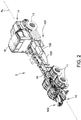
- the mixing system 100 is supported by a mobile hydro excavation vacuum apparatus 2.
- An example mobile hydro excavation vacuum apparatus may include on-board processing (e.g., liquid-solid separation) of earthen material generated during excavation such as the apparatus shown and described in U.S. Patent Publication No. 2019/0015766 , entitled “Cyclonic Separation Systems and Hydro Excavation Vacuum Apparatus Incorporating Same", which is incorporated herein by reference for all relevant and consistent purposes.
- the hydro excavation vacuum apparatus 2 is an example apparatus and the mixing system 100 may be used on other hydro excavation vacuum machines.
- the mixing system 100 may also be used on reclaimer systems (i.e., systems used for vacuuming and/or processing earthen material, but which do not include excavating functionality).
- Suitable apparatus also include apparatus which store and/or process drill cuttings.
- the mixing system 100 is shown and described as being supported by a mobile apparatus, in other embodiments the mixing system 100 is stationary (e.g., at a fixed location where materials are processed and the system 100 is secured by a supporting frame).
- the illustrated hydro excavation vacuum apparatus 2 includes a high pressure excavation and vacuum system 4, a separation system 6, and a dewatering system 8.
- the hydro excavation vacuum apparatus 2 includes a chassis 10 which support the various components of the mixing system 100. Wheels 11 are connected to the chassis 10 to transport the hydro excavation vacuum apparatus 2.
- the hydro excavation vacuum apparatus 2 may be self-propelled (e.g., the hydro excavation vacuum apparatus 2 includes a dedicated motor that propels the apparatus) or in some embodiments, the hydro excavation vacuum apparatus 2 may be adapted to be towed by a separate vehicle.
- the hydro excavation vacuum apparatus 2 may include a tongue and/or hitch coupler to connect to a separate towing vehicle.
- the hydro excavation vacuum apparatus 2 includes a rear 12, a front 14, and a longitudinal axis A 2 that extends through the front 14 and the rear 12 of the hydro excavation vacuum apparatus 2.
- the hydro excavation vacuum apparatus 2 includes a cab 16 arranged near the front 14.
- the mixing system 100 is supported by the chassis 10 substantially near the rear 12.
- the hydro excavation vacuum apparatus 2 is used to excavate a site by directing high pressure water to cut earthen material.
- the spoils including cut earthen material and water, is removed by a vacuum system 4 and processed on board of the hydro excavation vacuum apparatus 2 by the separation system 6 and the dewatering system 8 which are described further below.
- Spoil material that is processed may include, and without limitation, rocks, cut earthen material (e.g., small particulate such as sand to larger pieces of earth that are cut loose by the jet of high pressure water), and water used during excavation.
- the spoil material may have various ratios of liquid and solid materials such that spoil material that is processed has a wide-range of properties, e.g., consistencies, viscosities, and amounts of water.
- the terms used herein for material such as, for example, "spoils,” “spoil material,” “cut earthen material,” “earthen slurry”, and “water,” should not be considered in a limiting sense unless stated otherwise.
- the hydro excavation vacuum apparatus 2 includes a wand 20 that is used to direct pressurized water W towards earthen material at the excavation site, in order to cut the earthen material.
- the wand 20 is connected to an excavation fluid pump 22 that supplies water to the wand 20 (e.g., at a pressure of, for example, at least about 500 psi).
- the vacuum system 4 of the hydro excavation vacuum apparatus 2 is used to remove spoil material from the excavation site.
- the vacuum system 4 includes a boom 26 that is capable of rotating about the hydro excavation vacuum apparatus 2 to arrange the boom 26 in proximity to the excavation site, such that the boom 26 is enabled to remove spoil material.
- the boom 26 includes a flexible portion that may be manipulated by an operator to direct the vacuum suction toward the excavation site.
- the vacuum system 4 acts to entrain the cut earth and the water used to excavate the site in a stream of air.
- a blower or vacuum pump 28 pulls a vacuum through the boom 26 to entrain the material in the airstream. Air is discharged from the blower 28 after the material is removed from the air stream.
- the airstream having water and cut earth entrained therein is pulled through the boom 26 and through a series of conduits and is pulled into a separation vessel 30 which removes at least a portion of cut earthen material and water from the airstream.
- Air exits one or more separation vessel air outlets and is introduced into cyclones 32 to remove additional spoil material (e.g., water, small solids such as sand, low density particles such as sticks and grass, and the like) not separated in the separation vessel 30.
- Material that collects in the bottom of the cyclones 32 is conveyed by a cyclone discharge pump or, alternatively, is gravity fed to the dewatering system 8 described below.
- an airlock receives material from the separation vessel 30 and discharges the material through an airlock outlet.
- the hydro excavation vacuum apparatus 2 may process the spoil material to separate water from the excavated spoil material.
- the spoil material may be introduced into the dewatering system 8 to separate the spoil material into the solid fraction (which may have a semi-liquid quality) and the liquid fraction.
- the solid fraction may be further processed by the mixing system 100 on board the hydro excavation vacuum apparatus 2.
- the mixing system 100 processes the solid fraction to thicken the material until the solid fraction reaches the desired state (e.g., until the solid fraction may be classified as a "solid" for disposal purposes).
- the dewatering system 8 includes a pre-screen 40 that first engages material discharged from the outlet of the airlock (not shown).
- the pre-screen 40 has a plurality of slats with openings formed between slats through which material falls.
- the pre-screen 40 may have relatively large openings (e.g., at least about 0.5 inches) such that relatively large material is prevented from passing through the pre-screen 40.
- the pre-screen 40 may be adapted to withstand the impact of large stones and earthen material that are capable of being removed by the vacuum system 4.
- Example screens include screens that may be referred to by those of skill in the art as a "grizzly screener" or simply "grizzly.”
- the pre-screen 40 may vibrate or, as in other embodiments, does not vibrate.
- the dewatering system 8 includes a vibratory screen (not shown) that separates material that passes through the pre-screen 40 by size.
- the vibratory screen 42 has openings with a size smaller than the size of the openings of the pre-screen 40 (e.g., less than 250 micron).
- the vibratory screen 42 may be part of a shaker assembly 44 (more commonly referred to as a "shaker") that includes vibratory motors 46 that cause the screen to vibrate. As the screen vibrates, effluent falls through openings within the vibratory screen and particles that do not pass through the openings migrate to the discharge end 48 of the dewatering system 8.
- Liquid that passes through the vibratory screen 42 collects in a catchpan (not shown) and may be conveyed by a return water pump to a fluid storage and supply system.
- the dewatering system 8 includes additional or alternative separation devices such as flat wire belt conveyors, centrifuges, hydrocyclones or the like.
- Spoil material that reaches the discharge end 48 of the dewatering system 8 is introduced to the mixing system 100 as discussed in further detail herein.
- the spoil material that reaches the discharge end 48 of the dewatering system 8 falls into a bin (not shown) and then the bin may then be used to transport the spoil material to the mixing system 100.
- the spoil material that reaches the discharge end 48 of the dewatering system 8 may be transported to the mixing system 100 using a conveyor or any other suitable method.
- spoil material may be introduced to the mixing system 100 without first being processed in a dewatering system 8.
- the spoil material may be introduced to the mixing system 100 after the separation system 6 removes at least a portion of the cut earthen material and water from the air stream.
- spoil material that reaches the discharge end 48 of the dewatering system 8 i.e., the "solid-fraction" discharged from the shaker assembly 44
- the mixing system 100 may have a moisture-content and consistency that prevents the spoil material from being disposed using protocols suitable for spoils that have been classified as "solid", i.e., spoils having appropriate thickness and consistency.
- the appropriate thickness and consistency may alternatively be considered “stackable” or have properties quantifiable by the slump test or paint filter test described below.
- the consistency of the material may vary depending on the type of soil being processed.
- additive may selectively be added to the mixing system 100 depending on the consistency of the spoil material.
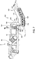
- the mixing system 100 includes a mixer housing 102 having a floor 104, a front wall 106, and a first sidewall 108 and a second sidewall 110.
- the front wall 106, the first sidewall 108 and the second sidewall 110 extend generally perpendicular to the floor 104.
- the front wall 106 extends, generally perpendicular to and between the first sidewall 108 and the second sidewall 110.
- the first sidewall 108 and the second sidewall 110 are generally parallel to each other and are disposed on opposite sides of the floor 104.
- the floor 104 of the mixing system 100 may be "closed", i.e., generally the floor 104 does not include outlets for material processed within the mixing system 100 other than openings for clean-outs and the like and/or a single discharge disposed toward the discharge end of the system 100.
- the mixing system 100 includes an inlet 112 for introducing earthen material into the mixer housing 102.
- the inlet 112 is disposed toward the front wall 106 of the mixer housing 102.
- the mixer housing 102 includes a cover 114 which defines at least a portion of the inlet 112. In other embodiments, the inlet 112 is defined between the first sidewall 108 and the second sidewall 110.
- the cover 114 extends generally perpendicular to and between the first and second sidewalls 108, 110.
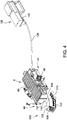
- the mixing system 100 includes an additive feed system 120 for adding a solidifying additive to the mixing system 100.
- the additive feed system 120 includes a feed vessel 122 that holds and stores a solidifying additive.
- the feed vessel 122 is coupled to the chassis 10 of the hydro excavation vacuum apparatus 2 in proximity to the cab 16.
- the additive feed system 120 further comprises an additive discharge 124 at which the solidifying additive is added to the mixing system 100.
- the additive discharge 124 includes a tube 126 which extends between the feed vessel 122 and the inlet 112 of the mixer housing 102.
- the tube 126 is flexible and extends generally along the chassis 10 ( Figures 1 and 2 ).
- the tube 126 includes a flexible auger 128 which is operably connected to a feed motor 129 ( Figure 6 ).
- the auger 128 is at least partially disposed within the tube 126 and the feed vessel 122.
- the flexible auger 128 may bend and flex with the tube 126.
- the feed motor 129 rotates the flexible auger 128 such that a metered amount of solidifying additive is conveyed from the feed vessel 122 along the tube 126 to the additive discharge 124 and is introduced into the mixer housing 102.
- the feed motor 129 may be coupled to a controller including a user interface which allows an operator to control and/or adjust the amount of additive introduced to the mixing system 100.
- the additive discharge 124 is disposed above the inlet 112 of the mixer housing 102. Accordingly, additive is introduced into the mixer housing 102 from the additive discharge 124 through the inlet 112 of the mixer housing 102.
- the solidifying additive may be any suitable additive that solidifies (e.g., thickens and/or agglomerates) the earthen material. Generally, the additive when mixed with the earthen material enables the earthen material to better hold it shape.
- the additive may include, for example and without limitation, lime, cement, bentonite, and suitable combinations thereof.
- various test and/or standards may be employed to classify earthen material as either a solid or a liquid, for disposal purposes.
- these tests quantify the slump and/or stackability of the discharged material.
- slump tests may be outlined in ASTM C 143 entitled “Standard Test Method for Slump of Hydraulic-cement Concrete", AASSHTO T 119 entitled “Slump of Hydraulic Cement Concrete”, or EPA SW-846 Test Method 9095B entitled “Paint Filter Liquids Test”, which are incorporated herein by reference for all relevant and consistent purposes.
- Other fluidic tests may be used to determine the liquidity of the earthen material.
- the solidifying additive thickens the spoil material such that it meets a criteria provided by the aforementioned tests, such the earthen material may be classified as solid and may be disposed of without restricted liquid spoil disposal protocols.
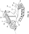
- the mixing system 100 further includes a vane assembly 134 ( Figures 8-9 ), also referred to herein as a "diffuser", arranged in proximity to the additive discharge 124 for spreading and/or diffusing the additive before the additive is introduced into the mixer housing 102.
- the illustrated diffuser 134 is an example and other diffuser designs may be used unless stated otherwise.
- the vane assembly 134 includes a plurality of vanes 136 which direct the additive from the additive discharge 124 and disperse the additive laterally across the inlet 112.
- the vanes 136 are arranged such that spaces between adjacent vanes 136 is smaller, in an area in proximity to the additive discharge 124, while the spaces between adjacent vanes 136 increases in a direction away from the additive discharge 124.
- the vane assembly 134 further includes a back plate 138 and an optional lower louver 140 ( Figure 12 ).
- the back plate 138 and the lower louver 140 direct additive in a forward direction, away from the front wall 106.
- the back plate 138 is eliminated and the front wall 106 of the mixer housing 102 acts as a back plate.
- the vane assembly 134 is coupled to the front wall 106 using any suitable methods, for example, rivets, bolts, and/or welding connections.
- the vane assembly 134 may be formed integrally with the front wall 106.
- the mixing system 100 includes a first shield plate 142 ( Figure 7 ).
- the first shield plate 142 has an inner surface 142a and an exterior surface 142b.
- the first shield plate 142 extends in front of the vanes 136, such that the inner surface 142a faces that vanes 136 and the exterior surface 142b (i.e., the opposite surface) faces away from the vanes 136.
- the first shield plate 142 is generally parallel to the front wall 106.
- the additive discharge 124 is arranged between the back plate 138 and the first shield plate 142, such that the additive passes through the vane assembly 134 between the first shield plate 142 and the back plate 138 before contacting the first disk assembly 156a described below.
- the first shield plate 142 may also extend in front of the lower louver 140.
- the inner surface 142a of the first shield plate 142 limits how far forward the additive first engages the disk assembly 156a.
- the additive discharge 124 includes a cap 144 ( Figure 12 ) that is rotationally coupled to the tube 126.
- the cap 144 may be hinged to the tube 126.
- the cap 144 covers the additive discharge 124 when additive is not introduced into the mixing system 100 and rotates out of the way by additive pushed by additive exiting the tube 126 during additive addition.
- the additive feed system 120 may further include a screen (not shown) that prevents large chunks of additive from entering the mixer housing 102.
- the mixing system 100 also includes a spoil material feed system 146 for adding spoil material (e.g., an earthen slurry) to the mixing system 100.
- the spoil material feed system 146 includes the dewatering system 8 (also referred to herein a shaker system) of the hydro excavation vacuum apparatus 2.
- the spoil material feed system 146 includes a solid fraction spoil material discharge 148 ( Figure 7 ), e.g., the discharge end 48 of the dewatering system 8, at which the solid fraction of the spoil material is added to the mixer housing 102.
- the spoil material discharge 148 is disposed in proximity to the inlet 112.
- the mixing system 100 includes a second shield plate 150 in proximity to the spoil material discharge 148 of the spoil material feed system 146 to direct spoil material into the mixing system 100.
- the spoil material discharge 148 is arranged between the exterior surface 142b of the first shield plate 142 and the second shield plate 150, such that spoil material passes between the first shield plate 142 and the second shield plate 150 before engaging the first disk assembly 156a.
- the second shield plate 150 may be a flexible material, for example rubber, which allows the second shield plate 150 to flex and bend while absorbing the vibrations of the dewatering system 8.
- the second shield plate 150 directs spoil material toward the mixing system 100 at the inlet 112.
- the first shield plate 142 separates the additive discharge 124 and the earthen material discharge 148, preventing mixing of the additive and the spoil material as they are both introduced into the mixer housing 102.
- the additive discharge 124 is disposed rearward to the spoil material discharge 148 relative to the longitudinal axis X 100 of the mixing system 100. In other words, the additive is added to the mixer housing 102 closer to the front wall 106, compared to the spoil material.
- the mixing system 100 includes a flow path P 102 that extends generally from the front wall 106 towards a mixer discharge end 152 of the mixer housing 102.
- the path P 102 may extend generally along a longitudinal axis Y 100 of the mixing system 100 which extends from the front wall 106 to the mixer discharge end 152 of the mixer housing 102.
- the mixer housing 102 includes a mixer discharge 154 for discharging material.
- the mixer discharge 154 is disposed toward the discharge end 152 of the mixer housing 102.
- the mixing system 100 includes a plurality of disk assemblies 156 (numbered from first disk assembly 156a to seventh disk assembly 156g)) disposed within the mixer housing 102.
- Each disk assembly 156 includes a rotatable shaft 158 (numbered from first rotatable shaft 158a to seventh rotatable shaft 158g) that extends from the first sidewall 108 to the second sidewall 110.
- Each of the rotatable shafts 158 includes a shaft axis X 158 about which the rotatable shaft 158 rotates.
- Each of the shaft axes X 158 of the plurality of rotatable shafts 158 is generally parallel to the other axes X 158 .
- Each disk assembly 156 includes a plurality of disks 160 connected to the each of the rotatable shafts 158.
- the plurality of disks 160 are each coupled to the rotatable shafts 158, such that rotations of the rotatable shafts 158 result in rotation of the plurality of disks 160.
- the disks 160 rotate in a direction such that the upper portion of each disk 160 rotates toward the discharge 154 of the mixing system 100 and the bottom portion of each disk rotates toward the front wall 106 of the mixing system 100.
- the disks 160 act collectively to mix the spoil material (e.g., the solid fraction discharged from the dewatering system 8) and the solidifying additive in a lower portion of the mixing system 100 (e.g., below the shaft axis X 158 ) and carry larger, thickened material in the upper section of the mixing system 100 (e.g., above the shaft axis X 158 and/or above the disks 160).
- the solidifying additive may be metered into the mixing system 100 at a desired rate (or even not at all if the spoil material is sufficiently solid). The larger chunks of material do not fall through the disks 160 and are carried by the disks 160 to the discharge 150. Smaller, more fluidic material falls through the disks 160 and mixes with additive.
- a discharge scraper 132 ( Figure 11 and 12 ) is positioned at the discharge 154 of the mixing system 100 which promotes separation of material from the disks 160 at the discharge 154.
- the discharge scraper 132 includes one or more prongs 133 which extend, generally perpendicularly, from the second section floor 178 to at least the common plane P 182 such that a prong 133 is disposed between adjacent disks 160.
- the disk assemblies 156 are divided into a first plurality 172 of disk assemblies 156 and a second plurality 182 of disk assemblies 156 (which may be referred to herein as a "first set 172" and "second set 182", respectively). At least a portion of the disks of the first set 172 of disk assemblies 156 are aligned such that a common plane P 172 runs through the shafts 158 of the first set 172 of disk assemblies 156. In addition, a least a portion of the disks of the second set 182 of disk assemblies are aligned such that a common plane P 182 runs through the shafts 158 of the second set 182 of disk assemblies.
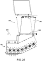
- the mixing system 100 and housing 102 is divided into a first section 162 and a second section 164.
- the first section 162 includes a first section housing 166 having a first section floor 168.
- the first section 162 generally does not include an outlet formed therein from which material is removed from the mixing system 100 (e.g., other than a hatch or other opening that may be selectively opened and closed to provide access to the first section 162 for performing an operation, such as a cleaning or repairing operation).
- the first set 172 of disk assemblies 156 is arranged within the first section 162 of the mixing system.
- the second section 164 of the housing 102 includes a second section housing 176 including an inclined floor 178 (also referred to herein as the second section floor 178) angled downward from the mixing system discharge 154 toward the first section floor 168.
- the second set 182 of disk assemblies is arranged within the second section 164.
- Disks 160 of each disk assembly 156 each has fingers 174 that extend radially outward from a disk central axis Y 160 of the disks 160 ( Figure 19 ). Each finger 174 includes a distal fingertip 175. The disks 160 have a radius R 160 that extends between the disk central axis Y 160 to the distal fingertips 175. As shown in the illustrated embodiment, the disks 160 are identical. In other embodiments, at least some disks 160 have a different size or shape than other disks of the mixing system 100.
- the first set 172 of disk assemblies 156 includes at least one, at least two, or at least three rotatable shafts 158 that extend between the first sidewall 108 and the second sidewall 110, above the first section floor 168. At least three, at least four or at least five disks 160 are connected to each of the rotatable shafts 158 within the first section housing 166.
- the second set 182 of disk assemblies includes at least one, at least two or at least three rotatable shafts 158 that extend from the first sidewall 108 to the second sidewall 110 with at least three, at least four or at least five disks 160 being connected to each of the rotatable shafts 158 within the second section housing 176.
- the spacing between disks, number of disks per row, number of rows and the size of the disks of the first and second assemblies 162, 164 as described and shown herein are exemplary and other spacing, number of disks, number of rows and the size of the disks may be used unless stated differently (e.g., depending on desired size of agglomerated materials, size of mixer and the like).
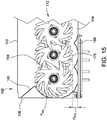
- the disks 160 of the first set 172 of disk assemblies is arranged in proximity to the first section floor 168.
- the disks 160 are arranged such that the distal fingertips 175 are a distance of H 175 relative to the first section floor 168.
- the distance H 175 may be less than 0.5 times the radius R 160 of the disk 160 ( Figure 15 ) or, as in other embodiments, less than 0.33 times the radius R 160 of the disk 160, less than 0.25 times the radius R 160 of the disk 160 or less than 0.1 times the radius R 160 of the disk 160 ( Figure 14 ).
- the distal fingertips 175 may reach and/or touch the first section floor 168.
- the first and second sets 172, 182 of disk assemblies 156 are arranged to propel material from the first section 162 into the second section 164 and through the mixing system discharge 154.
- the disks 160 propel the material generally along the path P 102 from the front wall 106 to the discharge end 152. In the view depicted on Figure 13 , the disks rotate in a clockwise direction to propel the material along path P 102 .
- the mixing system discharge 154 is the only outlet of the mixing system 100 through which processed material is discharged. At least a portion of the aggregated particles in the slurry are conveyed by the disks 160 to the discharge 154 and at least a portion of the slurry falls through the disks 160.
- the disks 160 cause a portion of the aggregated particles to be propelled toward the discharge and at least a portion of the slurry to be propelled toward the front wall.
- the portion that falls to the second section floor 178 may flow down the second section floor 178 and returns to the first section housing 166.
- the first section floor 168 and the second section floor 178 are connected together at the first section floor second end 168b and the second section floor first end 178a.
- the first section floor 168 and the second section floor 178 may be hinged and clamped together, may be formed integrally, or may be welded or fastened together in any other suitable manner.
- the second section floor 178 extends from the first section floor 168 at an angle ⁇ .
- the angle ⁇ may be between 5° and 60° or, as in other embodiments, between 5° to 45°, or between 5° and 30°. In yet other embodiments the angle is 0°.
- the first section floor 168 and the second section floor 178 may be arranged at any appropriate angle ⁇ that enables the mixing system 100 to function as described herein.
- the mixing system 100 is not divided into separate first and second sections that are angled relative to each other the disks are aligned such that a common plane runs through each of the shafts of the disk assembly.
- the mixing system 100 may be parallel to the ground ( Figure 20B ) or sloped upward toward its discharge end ( Figure 20C ).
- the mixing system 100 has a consistent width W 104 with the width of the first section 162 being approximately the same as a width of the second section 164. In some other embodiments, the width changes and/or tapers along the length of the system 100.
- the first section floor 168 includes a plurality of baffles 184 arranged in-between adjacent rotatable shafts 158.
- the baffles 184 are triangular in shape and extend upwards from the first section floor 168.
- the baffles 184 include a first surface 184a and a second surface 184b that directs spoil material and additive towards the disk assembly 156.
- the first and second surfaces 184a, 184b may be concaved.
- the baffles 184 extend substantially between the first sidewall 108 and second sidewall 110 and are generally parallel with the rotatable shafts 158.
- the baffles 184 prevent material from settling in space in-between adjacent rotatable shafts 158 that cannot be reached by the fingers 174 of the disks 160.
- the second section floor 178 does not include the baffles 184.
- the second section floor 178 serves to direct more fluidic earthen material downwards towards the first section 162.
- the baffles 184 are coupled to the first section floor 168 using bolts or other suitable fasteners or are integral with the first section floor 168.
- the plurality of disks 160 are arranged, along the length of the rotatable shaft 158 such that there is a distance L 160 between adjacent disks 160.
- the disks 160 are equally spaced along the length of the shaft 158, and a spacer 186 is disposed onto the shaft 158 between adjacent disks 160.
- the spacer 186 acts to maintain the arrangement of the plurality of disks 160 along the rotatable shaft 158.
- the first and second sets 172, 182 of disk assemblies 156 include additional components, such as washers, that maintain the distance L 160 between the disks 160 arranged on the rotatable shafts 158.
- each of the plurality of disks 160 includes a central portion 188 and a plurality of the fingers 174 that extend radially outward from the central portion 188.
- the central portion 188 defines a disk opening 190 and the rotatable shaft 158 is disposed within this disk opening 190.
- a boundary 192 of the disk opening 190 is sized and shaped to mate with an outer surface of the rotatable shaft 158.
- the disk opening 190 is defined by a hexagonal boundary 192 and the rotatable shaft 158 includes a corresponding hexagonal shape which mates with the hexagonal boundary 192 of the disk opening 190.
- the plurality of disks 160 and the rotatable shafts 158 include retaining features, such as keyed features and/or an alignment pin that is used to couple the plurality of disks 160 to the rotatable shafts 158.
- the plurality of disks 160 are coupled to the rotatable shaft 158 using a friction fit, i.e., the disks are press and/or shrink fit onto the rotatable shaft 158.
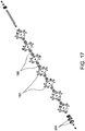
- One of more disks 160 may include a disk scraper 194 coupled to a distal portion of the finger 174 ( Figure 16 ).
- the disk scrapers 194 may be coupled to the fingers 174 using bolts or any other suitable methods.
- the disk scrapers 194 may be used to cut or break up the spoil material and/or the additive.
- the disk scrapers 194 may also scrape spoil material and additive that is disposed on the first section floor 168.
- the disks 160 adjacent to the discharge scraper 132 do not include disk scrapers 194 to allow the fingers 175 to pass between the prongs 133.
- the plurality of rotatable shafts 158 are operably coupled with at least one disk motor 196 ( Figure 8 ).
- the disk motor 196 rotates each of the rotatable shafts 158 ( Figure 12 ), and likewise the disks 160, about the shaft axis X 158 .
- the rotatable shafts 158 includes a drive section 198 ( Figure 8 ) that extends through an aperture formed on at least one of the first sidewall 108 and/or the second sidewall 110, such that the drive section 198 extends outside of the mixer housing 102 and may be operably connected to at least one of the disk motors 196.
- a first motor 202 is coupled at least one of the drive sections 198 of a rotatable shaft 158.
- the second section 164 includes a second motor 208 that is operably coupled to at least one of the drive sections 198 of the shafts 158.
- Adjacent rotatable shafts 158 of each section 162, 164 are operably coupled together using chains 206 (not shown) connected between sprockets 204 disposed on the drive sections 198 of the shafts 158.
- the first and the second motors 202, 208 may be used to control the rotational speeds of the first and second sets 172, 182 of disk assemblies 156, independently.
- the first motor 202 rotates the first set 172 at a first speed and the second motor 208 rotates the second set 182 at a second speed, different from the first speed.
- the first speed is less than the second speed.
- the first motor 202 rotates the rotatable shafts 158 of the first set 172 of disk assemblies 156 in the range of 100 - 200 revolutions per minute (rpm) and the second motor 208 rotates the rotatable shafts 158 of the second set 182 of disk assemblies 156 in the range of 0-300 rpm.
- the first and second motors 202, 208 are hydraulic motors that may be connected in series or in parallel. Each of the first and second motors 202 and 208 includes a torque arm 209 to support the first and second motors 202 and 208.
- the first and second motors 202, 208 may be connected to a controller including a user interface that enables an operator to control and adjust the rotational speeds to of the first and second sets 172, 182 of disk assemblies 156 independent of one another.
- the mixing system 100 may include any number of disk motors 196 enabling control of the rotational speeds of each of the disk assemblies 156.
- the aperture and/or the drive sections 198 which extends through the apertures on the mixer housing 102 may include sealing components which prevent leakage of the earthen material.
- the mixing system 100 may be operated to selectively add additive to the spoil material.
- the spoil material that enters the mixing system 100 is of sufficient quality (e.g., moisture content and/or thickness) that additive need not be added.
- the additive system 120 is not operated (e.g., motor 129 is not powered) and additive is not added to the mixing system 100. Spoil material is conveyed through the system 100 without additive being introduced into the system 100.
- the additive feed system 120 is operated and additive is added to the mixer system 100 with spoil material. Both the additive and the spoil material are introduced into mixer housing 102 into the first section 162 and onto the first disk assembly 156a.
- the additive discharge 124 is disposed rearward to the spoil material discharge 148 along the longitudinal axis X 100 , such that the additive reaches the disks 160, closer toward the front wall 106, compared to where the spoil material reaches the disks 160.
- the additive may pass through the spaces between the disks 160 and fall onto first section floor 168 or contact spoil material riding of the disks 160.
- the mixing of the additive and the earthen material generally occurs within the first section 162, below the common plane P 172 .
- the additive causes the spoil material to thicken and aggregate into particles which are carried toward the second section 164. In the second section 164, larger material continues to be carried by the disks 160 and moves toward the mixing system discharge 154. Smaller material falls to the second section floor 178 and may move toward the first section 162 to be further mixed with additive.
- the additive feed system 300 includes a feed vessel 302 for adding additive to the mixer housing 102.
- the additive feed system 300 includes an additive discharge 304 at which additive is added to the mixer housing 102.
- the additive discharge is disposed above the inlet 112.
- the additive feed system 300 also includes a conveyor 306 for conveying additive from the feed vessel 302 to the first section 162.
- the feed vessel 302 is supported, at least in part, by the mixer housing 102.
- the feed vessel 302 is supported above the mixer housing 102, such that the additive discharge 304 is disposed above the inlet 112.
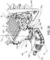
- FIG. 24-48 Another embodiment of the mixing system 100 is shown in Figures 24-48 .
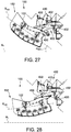
- the illustrated embodiment of the mixing system 100 is configured to tilt such that the angle ⁇ 400 ( Figure 26 ) between the longitudinal axis X 100 of the mixer housing 102 and the horizontal axis A x may be changed.
- the mixing system 100 includes a tilt assembly 400 ( Figure 24 ).
- the tilt assembly 400 enables the mixing system 100 to rotate about a tilt axis A 400 , such that the longitudinal axis X 100 of the mixer housing 102 may be selectively tilted relative to the horizontal axis A x .
- the horizontal axis A x is generally parallel to the ground and to the longitudinal axis A 2 ( Figure 1 ) of the vehicle 2.
- the tilt assembly 400 includes a first mount 402 ( Figure 26 ) and a second mount 404 ( Figure 44 ).
- the first and second mounts 402, 404 are connected (e.g., fixedly connected) to a frame (e.g., chassis) of the hydro excavation vacuum apparatus 2.
- the first mount 402 and second mount 404 are arranged opposite each other with one mount being arranged on each side of the mixing system 100.
- the second mount 404 may be substantially similar to the first mount 402 and include similar components to the first mount 402 as described below.
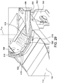
- the mixing system 100 includes an upper frame 406 ( Figure 29 ) and a lower frame 502. As described in more detail below, the lower frame 502 rotates relative to the upper frame 406 about a swivel axis Y 100 (i.e., the upper frame 406 and lower frame 502 are rotationally coupled).
- the upper frame 406 forms the inlet 112 of the mixing system 100.
- the lower frame 502 is connected to the mixer housing 102.
- the upper frame 406 ( Figure 26 ) is pivotally connected to the first mount 402 at a first joint 420.
- the mixing system 100 and the upper frame 406 may be selectively tilted about a tilt axis A 400 that extends through the first joint 420.
- the upper frame 406 is also pivotally connected to the second mount 404 ( Figure 44 ) at a second joint 421. Accordingly, the mixing system 100 and the upper frame 406 may rotate about the first joint 420 and the second joint 421 about the tilt axis A 400 which extends through both of the first joint 420 and the second joint 421.
- the tilt assembly 400 includes an arm 430 and an adjustment rod 432 (or simply "rod").
- the arm 430 is connected (e.g., rigidly connected) to the upper frame 406.
- the arm 430 is pivotally connected to the rod 432.
- the arm 430 may selectively translate along the rod 432 at a first end 452 of the arm 430 along a rod axis A 432 .
- the rod 432 is pivotally connected to the first mount 402.
- the rod 432 is threaded.
- the arm 430 is connected to a socket 442 by a mounting bolt 450.
- the socket 442 has a through-hole through which the threaded rod 432 passes.
- the socket 442 may move along the rod 432 by repositioning first and second nuts 444, 446 that are disposed on each side of the socket 442. Moving the arm 430 along the rod 432 selectively tilts the mixing system 100 about the tilt axis A 400 ( Figure 24 ) .
- a second rod 425 is pivotally connected to the second mount 404 and a second arm 431.
- the second arm 431 is rigidly connected to the upper frame 406.
- the second arm 431 is movable along the second rod 425, similar to the description provided above for the rod 432, the arm 430, and the first mount 402.
- the second mount 404, second rod 425, and second arm 431 are eliminated and the tilt assembly only includes a first mount 402, first arm 430 and first rod 432.
- the first and second arms 430, 431 may be moved along the respective rods 432, 425 at their first ends 452, 454 to selectively tilt the mixing system 100 in one of a plurality of tilted positions.
- the mixing system 100 may be selectively tilted about the tilt axis A 400 ( Figure 24 ) such that a tilt angle ⁇ 400 between the longitudinal axis X 100 and the horizontal axis A x may be selectively increased or decreased as shown in Figures 26-28 .
- angle ⁇ 400 By changing angle ⁇ 400 , the angle at which material is expelled through the discharge end 152 of the mixing system 100 also changes.
- the tilt assembly 400 may include one or more actuators (e.g., hydraulic or pneumatic cylinders or linear actuators).
- actuators may be substituted for the first and second rods 425, 432.
- rigid links maybe substituted for the first and second rods 425, 432.
- the mixing system 100 is configured to swivel about a swivel axis Y 100 .
- the mixing system 100 includes a swivel assembly 500 that enables the mixing system 100 to rotate about the swivel axis Y 100 .
- the upper frame 406 is rotationally connected to the lower frame 502 which is connected to the mixer housing 102.
- the lower frame 502 and the mixer housing 102 may be selectively rotated about the swivel axis Y 100 by the swivel assembly 500.
- the lower frame 502 is connected to at least one of the first sidewall 108, the second sidewall 110, and/or the cover 114.
- First and second sets of bearings 516, 518 enable the lower frame 502 to move relative to the upper frame 406.
- the first set of bearings 516 extend within a raceway 522. Inner surfaces of upper and lower collars 524, 526 ( Figure 25 ) of the upper frame 406 help define the raceway 522.
- the first set of bearings 516 support the weight of the mixing system 100.
- the second set of bearings 518 contact the lower collar 526 and facilitate rotational movement of the lower frame 502 relative to the upper frame 406.
- the lower frame 502 includes L-brackets 530 ( Figure 30 ) which secure the lower frame 502 to the upper frame 406.
- the L-brackets 530 may be removed to facilitate assembly or disassembly of the lower frame 502 to the upper frame 406.
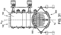
- the mixer housing 102 may be rotated about the swivel axis Y 100 to selectively position the longitudinal axis X 100 of the mixing system 100 and the discharge end 152 relative to the longitudinal axis A 2 ( Figure 1 ) of the vehicle 2.
- the mixer housing 102 may be rotated such that the discharge end 152 is aligned with the axis A 2 ( Figure 31 ) or the mixer housing 102 may be rotated to position the discharge end 152 on either side of the axis A 2 ( Figures 32 and 33 ).
- the mixer housing 102 may be rotated manually by an operator, e.g., an operator may push on the mixer housing 102 to rotate the mixer housing 102.
- a motor may be used to rotate the mixer housing 102.
- a locking mechanism (not shown) may be used to secure the rotational position of the mixing system 100 by coupling together the upper frame 406 and the lower frame 502.
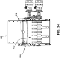
- the mixing system 100 includes a distribution assembly 600, shown in Figures 34-42 .
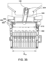
- the distribution assembly 600 distributes solidifying additive across the width W 104 ( Figure 35 ) of the mixer housing 102 to spread and/or distribute the solidification additive as it is introduced into the mixer housing 102.
- the distribution assembly 600 may be positioned such that solidifying additive is introduced onto the first disk assembly 156a ( Figure 12 ).
- the distribution assembly 600 may be used as an alternative to the vane assembly 134 ( Figure 9 ).
- the distribution assembly 600 includes a housing 602 ( Figure 38 ) defining a chamber 606 therein.
- the housing 602 extends from a first end 608 ( Figure 37 ) to a second end 610.
- the distribution assembly 600 includes a first mounting plate 612 and a second mounting plate 614.
- the distribution assembly 600 includes a neck 618 having in inlet 616 for receiving solidifying additive.
- Solidifying additive is delivered to the distribution assembly 600 using the tube 126 ( Figure 36 ) and the flexible auger 128 ( Figure 6 ), as described above.
- a distal end 624 ( Figure 36 ) of the tube 126 may include tubing 626 (e.g., flexible tubing) which connects to the neck 618 of the distribution assembly 600.
- the tubing 626 may be flexible and have the ability to rotate and/or flex with the movement of the mixer system 100, such that the solidifying additive may be delivered to the distribution system 600 independent of the position of the mixing system 100.
- the tubing 626 delivers solidification additive to the distribution assembly 600 while the mixing system 100 may be selectively rotated about the swivel axis Y 100 ( Figure 24 ) and/or tilted about the tilt axis A 400 .
- the tubing 626 sits within a linkage 635 which guides the tubing 626 toward the neck 618 of the distribution assembly 600.
- a chute is connected to the tubing 126 and the distribution assembly 600 to guide material from the tube 126 to the distribution assembly 600.
- the distribution system 600 is generally shown as a screw auger.
- the system includes a screw 630 connected to a shaft 640.
- the screw 630 and shaft 640 rotate within the chamber 606.
- the screw 630 is a dual ended screw including a first screw portion 632 and a second screw portion 634.
- the first screw portion 632 is a first handed screw (i.e., the first screw portion has flightings in a first direction)
- the second screw portion 634 is a second handed screw (i.e., the second screw portion 634 has flightings in a second direction that is opposite the first direction) such that the solidification additive moves in opposite directions.
- Rotations of the screw 630 convey the solidifying additive outwards, away from the inlet 616, towards the first end 608 ( Figure 35 ) and the second end 610.
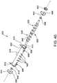
- the distribution assembly 600 includes a first end cap 642 and a second end cap 644 each including an aperture 646 formed therein.
- the end caps 642, 644 each support a bearing 648 disposed within the aperture 646.
- the aperture 646 is sized and shaped to receive the shaft 640 and the bearing 648 enables the screw 630 to rotate.
- the shaft 640 extends outward from the housing 602 through each aperture 646.
- the shaft 640 is coupled to a drive gear 652 such that the shaft 640 may be operably coupled to a drive motor using suitable mechanisms, such as drive chain and/or sprockets.
- the shaft 640 may be operably coupled to at least one of the disk motors 196 ( Figure 8 ) using a chain connected between the drive gear 652 and sprockets 204.
- a designated hydraulic and/or electric motor (not shown) is operably coupled to the shaft 140 which drives the rotations of screw 630.
- the housing 602 also includes outlets 662, 668 which allows the solidifying additive within the chamber 606 to exit the chamber 606 and fall into the mixer housing 102 and onto the first disk assembly 156a and/or onto the lower louver 140.
- a first set of outlets 662 each have a generally oval shape. Alternatively, each of the outlets of the first set 662 may be generally circular in shape.
- a second set of outlets 668 is disposed near the first end 608 and the second end 610 of the housing 602.
- the second set of outlets 668 are generally triangular in shape and allow the remainder of the solidification additive that did not pass through the outlets of the first set 662 to exit the chamber 606 and fall into the mixer housing 102.
- the distribution assembly 600 may include any suitable number of outlets having any suitable arrangement allowing the solidification additive to exit the chamber 606 to disperse over the width W 104 ( Figure 35 ) of the mixer housing 102 as the additive material is conveyed towards the first and second ends 608, 610.
- the distribution assembly 600 is removably coupled to the mixing housing 102 such that an operator may readily detach the distribution assembly 600 for cleaning or clearing of the distribution assembly 600.
- the distribution assembly 600 may detach and be reattached using suitable fasteners such as clips and/or pins 669 ( Figure 37 ), allowing an operator to toollessly detach and/or reattach the distribution assembly 600.
- At least one of the first or second mounting plates 612, 614 includes a first locking aperture 670 ( Figure 40 ) that may be aligned with a second locking aperture 672 ( Figure 42 ) on the mixer housing 102. Pins 669 may be received in the first and second locking apertures 670, 672 to mount and attached the distribution assembly 600 to the mixer housing 102.
- the distribution assembly 600 may include a screw that is a single handed screw having flightings in a single direction.
- the inlet 616 may be positioned at one either the first end or the second end 608, 610 and the singlehanded screw conveys solidification additive introduced into the inlet 616, across the width W 102 ( Figure 35 ) of the mixer housing 102.
- the mixing system 100 includes an adjustable floor assembly 700 as shown in Figures 43-48 .
- the adjustable floor assembly 700 includes a floor 702 (e.g., closed floor) which may be similar to floor 104 ( Figure 7 ).
- the adjustable floor assembly 700 enables the floor 702 of the mixer housing 102 to be selectively lowered and/or raised relative to the disk assemblies 156.
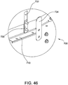
- the floor 702 is connected to a first sub-floor bracket 704 ( Figure 44 ) and a second sub-floor bracket 706.
- Each of the first and second sub-floor brackets 704, 706 includes a panel 708 and a flange 710 extending perpendicularly from the panel 708.
- the panel 708 is parallel to the first and second sidewalls 108, 110 and is perpendicular to the floor 702.
- the first and second sub-floor brackets 704, 706 are arranged such that the panels 708 are within the mixer housing 102 adjacent to an internal surface 709 of each of the first and second sidewalls 108, 110.
- One or more mounting arms 712 are coupled to each of the first and second sub-floor brackets 704, 706.
- the mounting arms 712 extend upward from the flange 710 such that the mounting arms 712 are generally parallel to the panel 708.
- the mounting arms 712 are arranged external to the mixer housing 102 adjacent to an external surface 711 of the mixer housing 102.
- a first end of at least one actuator 714 is coupled to the first and second sidewalls 108, 110.
- the mounting arm 712 includes a rib 716 which is coupled to a second end of the actuator 714.
- the actuator 714 transmits a force to move the floor 702 upward and downward.
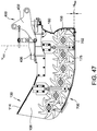
- the actuator 714 may be used to adjust the distance between the floor 702 and the disk assembly 156 ( Figures 47-48 ).
- the floor 702 is a distance H 700 from the distal fingertips 175 of the disks 160.
- This distance H 700 may be decreased ( Figure 47 ) such that the disks 160 contact the floor 702 or may be increased ( Figure 48 ) to provide more clearance between the floor 702 and the disks 160.
- Adjusting the vertical position of the floor 702 relative to the disk assemblies allows for changes in the mixing characteristics and/or for a cleaning or clearing operation to be performed. For example, moving the floor 702 away from the disks 160 ( Figure 48 ) provides a clearance between the floor 702 and the disk assembly 156 to clear out debris, such as sticks, plugs, rocks, or any other similar debris. Additionally, the disk assembly 156 may be run (rotated) in reverse to assist in a clearing operation.
- a lower edge 724 of the first and second sidewalls 108, 110 is displaced from the floor 702 creating a gap 726 ( Figure 45 ) therebetween.
- the panels 708 have a height that is sufficient to cover the gap 726. Additionally, the panels 708 may have a scalloped edge 728 ( Figure 44 ) that provides a clearance to prevent the panels 708 from interfering with the disk assemblies 156. Accordingly, the adjustable floor assembly 700 is closed, regardless of the vertical position of the floor 702, preventing spoil material from exiting the mixer housing 102.
- a bearing surface is disposed between the housing side panels 108, 110 and the floor panels 708.
- guides 730 are coupled to the first and second sub-floor brackets 704, 706 ( Figure 44 ) and extend outward from the panel 708.
- the first and second sidewalls 108, 110 include a slot 732 that is sized to receive at least a portion of the guide 730.
- the plurality of guides 730 and the slots 732 maintain the alignment of the floor 702 as it is caused to move vertically by the actuators 714.
- the guides 730 may include a cover plate 734, which may be arranged external to the mixer housing 102 and is coupled to the guide 730 using a suitable fasteners, such as bolts.
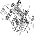
- FIG. 49-55 Another embodiment of the mixing system 100 is shown in Figures 49-55 .
- the illustrated embodiment of the mixing system 100 may be substantially the same as the mixing system 100 described above with respect to Figures 24-48 , except as described below.
- the disk assemblies 156 of the illustrated mixing system 100 each include a plurality of lobed disks 160 mounted on the rotatable shafts 158. When assembled on shaft 158, the lobed disks 160 are each positioned in contact with at least one adjacent disk 160 on the same shaft 158 to substantially close any gaps between the disks 160. In other embodiments, the lobed disks 160 may be spaced from adjacent disks 160 on the same shaft 158 such that gaps (not shown) are defined between adjacent disks 160.
- the disk 160 in the illustrated embodiment has an oval profile defining a major axis M 1 and a minor axis M 2 .
- the disk 160 includes a hub 802, a center bore 804 defined within the hub, spokes 806, and a rim 808.
- the rim 808 defines two lobes 810 of the disk 160 at opposed ends of the disk along the major axis M 1 .
- the center bore 804 has a generally hexagonal shape and is sized to receive one of the rotatable shafts 158 axially (i.e., into the page in Figure 53 ) therethrough.
- the spokes 806 radiate outward from the hub 802 to the rim 808 and define a plurality of openings 812 therebetween.
- the openings 812 provide an extra level of mixing for spoil material (e.g., such as clay chunks) that may become at least partially contained within the disks 160 during operation.
- the disks 160 do not define openings 812 between the hub 802 and the rim 808.
- the rim 808 of the illustrated disk 160 includes an outer surface 814.
- the outer surface 814 defines a timing notch 816 therein.
- the timing notch 816 is defined in the rim 808 at a position along the minor axis M 2 of the disk 160.
- the timing notch 816 facilitates orienting the disk 160 on the rotatable shaft 158 in accordance with a desired arrangement of the disk assemblies 156.
- the disk assemblies 156 each include a number of disk pairs with the two disks of each pair being oriented in alignment with each other on the rotatable shaft 158.
- the disk pairs are oriented or "timed”, on the shafts 158 to be angularly offset from an adjacent disk pair, such that the disk assemblies 156 have an arrangement defined by opposed helixes along the rotatable shaft 158.
- a first group of disks 160a of the rear disk assembly 156a includes disk pairs that are offset from each of the other disk pairs in the group of disks 160a (i.e., the lobes 810 of the disks 160a shift about the shaft 158 as they progress from a first end (not shown) of the rotatable shaft 158 at the first housing sidewall 108 to a central disk pair 818 in a first rotational direction such as the clockwise direction as viewed in Figure 50 ).
- a second group of disks 160b on the rear disk assembly 156a includes disk pairs that are offset from adjacent disk pairs such that the lobes 810 shift in a second, opposite, rotational direction (i.e., the counter-clockwise direction in Figure 50 ) as the pairs progress from the central disk pair 818 to the second end 159 of the rotatable shaft 158 at the second housing sidewall 110.
- a similar timing of the disks 160 on the disk assemblies 156 is also shown with respect to the embodiment illustrated in Figure 59 , as described in greater detail below.
- more than two disks 160 may be aligned (3, 4, 5 or more aligned in a group).
- each disk 160 is not aligned with an adjacent disk 160 but is angularly offset from adjacent disks 160.
- each disk assembly 156 including an end disk 160 positioned at the second ends 159 of the rotatable shafts 158.
- the illustrated end disks 160 are each positionally aligned along the flow path P 102 .
- the remaining disks 160 shown in Figure 50 are removed for clarity in Figure 52 , though it should be understood that the positional relationship described with respect to the illustrated end disks 160 of adjacent disk assemblies 156 in Figure 52 is the same for the remaining disks 160 of the disk assemblies 156.
- the end disks 160 are offset by an angle ⁇ from the positionally aligned end disks 160 of adjacent disk assemblies 156.
- the first end disk 160 of the fifth disk assembly 156e and the first end disk 160 of the sixth disk assembly 156f are oriented on their corresponding rotatable shaft 158 such that the angle ⁇ (defined by the intersection of the major axes M 1 of the end disks 160) is approximately 90 degrees.
- the rotatable shafts 158 are each connected to one another by a plurality of drive chains 820 that synchronize the rotational speed of each of the rotatable shafts 158.
- the illustrated orientation or "timing" of the end disks 160 relative to the adjacent end disks 160 prevents material from being pinched between the disk assemblies 156 by maintaining the same size of the gaps 822 ( Figure 52 ) defined between the positionally aligned disks 160 as the disk assemblies 156 are rotated.
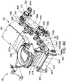
- Figures 56-60 illustrate another embodiment of a mixing system 100.
- the mixing system 100 of Figures 56-60 is substantially the same as the mixing system 100 of Figures 49-55 except that, in the illustrated embodiment, the mixing system 100 includes alternative disk assemblies 156 having trilobed disks 160 and a plurality of floor inserts 824 attached to the floor 702.
- the trilobed disks 160 are shaped to have a Reuleaux triangle profile having three lobes 810.
- a longitudinal axis M 3 of the trilobed disk 160 is defined extending through one of the lobes 810 and an opposed point directly between the other two lobes 810.
- the trilobed disks include a hub 802 defining a central bore 804 and a plurality of spokes 806 radiating out from the hub 802 to the rim 808.
- the spokes 806, rim 808, and hub 802 collectively define a plurality of openings 812 extending through the disks 160 though, as described above with respect to the bilobed disks 160, in other embodiments the disks 160 do not include the openings 812.
- Timing notches 816 are defined in an outer surface 814 of the trilobed disks 160.
- the trilobed disks 160 are positioned in direct contact on the disk assembly shaft 140 and are angularly offset in pairs.
- the trilobed disks 160 are oriented on the shaft 140, or "timed", to define an opposed helix shape of the disk assembly 156.
- the trilobed disks 160 have a relatively smaller rotational profile. Accordingly, in the illustrated embodiment, inserts 824 are provided to support the spoil material above the floor 702 and reduce the open space between the disks 160 and the spoil material. In the illustrated embodiment, the inserts 824 are metal plates supported by legs attached to the floor 702 or front wall 106 of the mixer housing 102. In other embodiments, an alternative housing may be used with the trilobed disks 160 that has a reduced clearance between the floor 702 and the disk 160. In further embodiments, a floor adjustment assembly, similar to the floor adjustment assemblies described with respect to Figures 43-48 or Figures 49-55 may be provided to adjust the position of the floor 702 relative to the rotatable shafts 158.
- each disk assembly 156 including an end disk 160 positioned at the second ends 826 of the rotatable shafts 158.
- the illustrated end disks 160 are each positionally aligned along the flow path P 102 .
- the remaining disks 160 shown in Figure 56 are removed for clarity, though it should be understood that the positional relationship described with respect to the illustrated end disks 160 of adjacent disk assemblies 156 in Figure 57 is the same for the remaining disks 160 of the disk assemblies 156.
- the end disks 160 are oriented in parallel, or "timed at zero degrees offset" from the positionally aligned end disks 160 of adjacent disk assemblies 156.
- a first end disk 160 of the first disk assembly 156b is oriented on the corresponding rotatable shaft 158 such that the longitudinal axis M 3 of the first end disk 160 is parallel to the longitudinal axis M 3 of a second end disk 160 on a second adjacent disk assembly 156c.
- the illustrated orientation or "timing" of the trilobed disks 160 relative to the adjacent disk assemblies 156 maintains the same size of the gaps 822 defined between the positionally aligned disks 160 as the disk assemblies 156 are rotated at the same velocity.
- the mixer housing 102 further includes a drive system 828 including two motors 202, 208 that are operable to drive rotation of the rotatable shafts 158.
- a first motor 202 is attached to the fifth rotatable shaft 158e and a second motor 208 is attached to the second rotatable shaft 158b.
- a support arm 830 is attached to the first housing sidewall 108 and extends therefrom to connect to a pair of torque arms 832.
- the torque arms 832 support the motors 202, 208 on the mixer housing 102 and inhibit rotation of the motor housings 834 relative to the rotatable shafts 158.
- the drive system 828 further includes a plurality of drive chains 820 and sprockets 836 connecting the rotatable shafts 158.
- at least one sprocket 836 is attached to each rotatable shaft 158.
- the drive chains 820 connect the sprockets 836 between adjacent rotatable shafts 158 to synchronize rotation of the shafts 158.
- the sprockets 836 in the illustrated embodiment are each similarly sized such that actuation of the motors 202, 208 causes each of the rotatable shafts 158 to rotate at approximately the same rotational velocity and maintain the spacing of the gaps 822 between the disk assemblies 156 ( Figure 52 ) during rotation.
- Synchronizing rotation of the shafts 158 also prevents the disk assemblies 156 from interfering with or obstructing rotation of adjacent disk assemblies 156.
- at least one of the sprockets 836 may have a different size and/or a different number of teeth from another one of the sprockets 836 to impart a different rotational velocity on one of the shafts 158.
- the drive system 828 may include only one motor or more than two motors.
- the drive system 828 is any suitable drive system 828 that is operable to drive rotation of the rotatable shafts 158.
- the drive system 828 is a spur gear drive system that includes one or more spur gears (not shown).
- the mixer housing 102 further includes a distribution assembly 600 that is substantially the same as the distribution assembly 600 shown and described with respect to Figures 37-42 .
- the drive system 828 also includes an additive drive system 838 for driving a drive gear 652 of the distribution assembly 600.
- the additive drive system 838 includes a sprocket 840 attached to the first rotatable shaft 158a, the drive gear 652 of the distribution assembly 600, and a drive chain 842 connecting the sprocket 840 to the drive gear 652.
- a tensioner 844 is connected to the drive chain 842 to maintain tension in the drive chain 842 during operation.
- the tensioner 844 includes a tensioning arm 846, a sprocket 848 attached on the tensioning arm 846 and engaged with the drive chain 842, and a biasing element 850.
- the biasing element 850 biases the tensioning arm 846 and the sprocket 848 away from the drive gear 652 and the sprocket 840.
- similar tensioners 844 and/or other known tensioners may be provided to maintain tension in each of the drive chains 820 on the rotatable shafts 158.
- the illustrated mixing system 100 further includes an alternative adjustable floor assembly 700 that enables the floor 702 of the mixer housing 102 to be selectively lowered and/or raised relative to the disk assemblies 156.
- lowering the floor 702 may enable a clean out operation to remove various debris (e.g., sticks, plugs, rocks, etc.) that may accumulate on the floor.
- the floor 702 may be moved to provide additional clearance for mixing the spoil material and/or to accommodate different sized disk assemblies 156.
- the adjustable floor assembly 700 is substantially the same as the adjustable floor assembly 700, shown and described with respect to Figures 43-48 , except as described below.
- the adjustable floor assembly 700 of Figure 49 includes a single actuator 852 and a linkage assembly 854 that connects the actuator 852 to the floor 702.
- the linkage assembly 854 is configured to translate movement of the actuator 852 into vertical movement of the floor 702.
- Figure 54 is a side view of the mixing system 100 with the floor 702 in the raised position and Figure 55 is a side view that shows the floor 702 in the lowered position. Additional components are removed in Figure 55 to show features of the adjustable floor assembly 700.
- the actuator 852 is a hydraulic actuator that includes a cylinder 856 ( Figure 55 ) and a piston 858. In other embodiments, any suitable actuator may be used.
- the cylinder 856 is attached to the outer cover 114 and configured to be pressurized to extend and retract the piston 858 from the cylinder 856.
- Other actuators such as linear actuators or any mechanically driven actuator may alternatively be used.
- the piston 858 is in an extended position relative to the cylinder 856 when the floor 702 is in the raised position ( Figure 54 ) and is retracted when the floor 702 is in the lowered position ( Figure 55 ).
- the linkage assembly 854 includes a pivot bracket 860 connected to the piston 858 of the actuator 852.
- the pivot bracket 860 defines a slot 862 that receives a projection 864 of the piston 858 therein.
- the linkage assembly 854 further includes, a connecting shaft 866, first, second, and third arms 868, 870, 872, and first, second, and third linkages 874, 876, 878.
- the linkages 874, 876, 878 have a selectively adjustable length to achieve a desired range of motion of the linkages 874, 876, 878.
- the connecting shaft 866 is rotatable within bearings 880 ( Figure 49 ) attached to the cover 114.
- the pivot bracket 860 is attached to and rotates with the connecting shaft 866 about a first center axis C 1 extending through the connecting shaft 866 (into the page in Figure 55 ).
- the first and second arms 868, 870 are each attached to the connecting shaft 866 and positioned outward from the first housing sidewall 108.
- the first linkage 874 is pivotably attached to the first arm 868 and is connected to a first mounting arm 882 attached to the floor 702 by a first clevis and tang connector 886.
- the second linkage 876 is pivotably attached to the second arm 870 and the third arm 872.
- the third arm 872 is pivotably attached to the first housing sidewall 108.
- a mounting bracket 888 is attached to the second sidewall 110 and the third arm 872 is connected to the mounting bracket 888 by a pin connector 890 extending through the mounting bracket 888 and third arm 872.
- the third arm 872 is configured to rotate around a second center axis C 2 extending through the pin connector 890 (into the page in Figure 55 ).
- the third arm 872 includes a first prong 892 and a second prong 894 each extending radially outward from the pin connector 890.
- the second linkage 876 is pivotably attached to the third arm 872 at the first prong 892 and the third linkage 878 is pivotably attached to the third arm 872 at the second prong 894.
- the second prong 894 is angularly offset from the first prong 892 such that the generally lateral movement of the first prong 892 by the second linkage 876 is translated into generally vertical movement of the second prong 894 and the third linkage 878.
- the third linkage 878 is also connected to a second mounting arm 884 by a second clevis and tang connector 896.
- the second mounting arm 884 is attached to the floor 702.
- the floor 702 also includes guides 730 which maintain the alignment of the floor 702 during raising and lowering of the floor 702 in substantially the same manner as described above with respect to guides 730 shown in Figure 44 .
- the linkage assembly 854 also includes additional arms and linkages on the opposed side of the mixing system 100 (shown partially in Figure 9 ) that are arranged to connect the actuator 852 to the floor 702 in substantially the same manner as described herein with respect to the first through third linkages 874, 876, 878 and the first through third arms 868, 870, 872.
- the circumferential rotation of the second arm 870 moves the second linkage 876 (e.g., to the left of the page as shown in Figure 54 ), thereby rotating the third arm 872 around the second center axis C 2 (e.g., in the clockwise direction as shown in Figure 54 ).
- the second linkage 876 moves the first prong 892 of the third arm laterally (e.g., to the left of the page in Figure 54 ) which moves the second prong 894 generally vertically downward. Movement of the second prong 894 lowers the third linkage 878 and the second mounting arm 884.
- the pivotable connections between the first, second, and third linkages 874, 876, 878 and the guides 730 facilitate maintaining alignment of the floor 702 with the first housing sidewall 108 between the raised and lowered positions and restrict lateral movement of the floor 702.
- Figures 60-64 show another embodiment of a mixing system 100.
- the mixing system 100 is substantially the same as the mixing system 100, described above with respect to Figures 24-48 , except as described below.
- the mixing system 100 includes a mixer housing 102 and a conveyor assembly 900 pivotally attached to the mixer housing 102.
- the conveyor assembly 900 is configured to carry material within the mixer housing 102 in either a forward direction (i.e., from the front wall 106 towards the discharge end 152) or in an opposite reverse direction.
- the disks 160 mix and at least partially solidified spoil material in the mixer and convey the solidified spoil material to the discharge end 152.
- an additional drive to move the spoil material within the mixer housing 102 may be desirable.
- the spoil material may include fine grain particles, such as sand, that are not easily carried by the disks 160.
- the mixing system 100 may operate in a "pass through" mode, in which the spoil material is conveyed through the mixer housing 102 with only a small amount or no additive mixed in.
- the conveyor assembly 900 facilitates moving the material within the mixer housing 102 to the discharge end 152.
- the conveyor assembly 900 may be used to clear obstructions in the mixer housing (such as rocks or gravel) that may otherwise become impacted into the floor and cause the disks 160 to become mechanically bound.
- the conveyor assembly 900 is a belt conveyor that includes a conveyor housing 902, a belt 904, and conveyor shafts 906 rotatably connected to the conveyor housing 902 operable to drive movement of the belt 904 around the conveyor shafts 906.
- the conveyor housing 902 includes a first sidewall 908 and a second sidewall 910 ( Figure 61 ).
- a pivot bar 912 extends between and connects the first and second sidewalls 908, 910 of the conveyor housing 902.
- a pair of bosses 914 extend longitudinally outward from the front wall 106 of the mixer housing 102 and the pivot bar 912 extends through apertures 916 ( Figure 61 ) defined in the bosses 914.
- bearings are provided between the pivot bar 912 and the bosses 914 to reduce wear resulting from friction at an interface between the pivot bar 912 and the bosses 914.
- the illustrated configuration of the pivot bar 912, the bosses 914 and the conveyor housing 902 enables the conveyor assembly 900 to pivot relative to the mixer housing 102.
- the mixer housing 102 includes a drive system 828 ( Figure 60 ) that includes a first, or lower, group 161 of rotatable shafts 158 (numbered 158a-158c) and a second, or upper, group 163 of rotatable shafts 158 (numbered 158d-158f).
- a first motor 202 is operably connected, via drive chains 820, to drive the first group 161 of rotatable shafts 158 and a second motor 208 is operably connected, via drive chains 820, to drive the second group 163 of rotatable shafts 158.
- the rotatable shafts 158 are separated into different drive groups 161, 163 to facilitate operating the different groups of shafts at different rotational velocities.
- the second group 163 of rotatable shafts 158 may be rotated at a higher rotational velocity than the first group 161 to keep spoil material moving upwards towards the discharge end 152.
- the first group 161 and the second group 163 may be operated in opposing rotational directions simultaneously.
- the drive systems 828 of Figures 51 and 60 may alternatively be used on any of the mixing systems 100 described herein.
- the conveyor assembly 900 also includes a conveyor motor 918 operably engaged with at least one of the conveyor shafts 906 to rotate the conveyor shafts 906.
- the conveyor assembly 900 includes a front conveyor shaft 906a and a rear conveyor shaft 906b ( Figure 62 ).
- the conveyor motor 918 drives rotation of the rear conveyor shaft 906b to move the belt 904 on the shafts 906.
- the conveyor housing 902 includes an anti-rotational mount 920 ( Figure 60 ) attaching a motor housing 922 of the conveyor motor 918 to the first conveyor housing sidewall 908.
- the anti-rotational mount 920 inhibits rotation of the motor housing 922 relative to the conveyor housing 902.
- the belt 904 is a smooth conveyor belt (i.e., the belt has a substantially smooth surface that contacts the spoil material during use).
- the belt 904 may include any suitable conveyor belt having any known belt features (e.g., protruding ribs, treads, etc.) for engaging the spoil material.
- the mixer housing 102 further includes at least one laterally extending flange 924 that is positioned to contact and engage the belt 904 during operation.
- the flange 924 contacts and seals against the belt 904 during operation to prevent, or at least substantially inhibit, spoil material within the housing from moving laterally beyond the flange 924.
- the flange 924 defines a generally arched concave contour and engages the belt 904 to define a generally arched convex contour of the belt 904 between the conveyor shafts 906.
- the flange 924 may be shaped in any manner that enables the mixer housing 102 to function as described herein.
- the housing 102 includes a first laterally extending flange (not shown) protruding laterally outward from a bottom of the first housing sidewall 108 and a second lateral flange 924 protruding laterally outward from a bottom of the second housing sidewall 110.
- at least one of the flanges 924 may protrude laterally inward (i.e., toward the disks 160) from at least one of the housing sidewalls.
- a plurality of triangular gussets 926 are provided to support and inhibit bending or deformation of the flanges 924.
- the flange 924 is formed of a metal material.
- the flange 924 is formed of a lubricant impregnated wear material.
- a strip (not shown) formed of a wear resistant metal or wear resistant material such as, but not limited to, ultra high molecular weight polyethylene, nylon, etc. may be provided on the flange 924.
- the conveyor housing 902 includes a belt tensioning assembly 928 that controls tension and prevents slipping of the belt 904.
- the belt tensioning assembly 928 includes a tensioner shaft 930 rotatably received within a bearing element 932.
- a plurality of pulleys 934 are attached along the tensioner shaft 930 and are configured to rotate therewith. The pulleys 934 contact and engage a lower section 904b of the belt to apply a downward force on the belt 904.
- the bearing element 932 is slidably received in a mount 936 attached to the conveyor housing 902.
- a biasing assembly 938 ( Figure 63 ) is attached to the conveyor housing 902 and includes a biasing element 940 that biases the bearing element 932 downward within the mount 936.
- the biasing element 940 is a compression spring, though in other embodiments, any suitable biasing element may be used.
- the biasing assembly 938 may be selectively adjustable and/or positionable to adjust the belt 904 tension.
- the mixer housing 102 further includes at least one actuator 942 attached to the mixer housing 102 that is configured to attach to the conveyor housing 902.
- a first actuator 942a is mounted on the first mixer housing sidewall 108 ( Figure 60 ) and a second actuator 942b is mounted on the second mixer housing sidewall 110.
- the actuators 942 each include clevis and tang connectors 944 that connect to corresponding mounts 937 on the conveyor housing 902.
- the actuators 942 are linearly extendable to move the conveyor assembly 900 between a raised position (shown in Figure 63 ), and a lowered position (shown in Figure 64 ).
- the flanges 924 contact and engage the belt 904 ( Figure 61 ) along substantially the entire length of the belt 904 between the conveyor shafts 906.
- the actuators 942 are extended, pivoting a front end 952 of the conveyor housing 902 about the pivot bar 912 and lowering a rear end 950 of the conveyor housing 902 relative to the mixer housing 102.
- a gap 948 is defined between the mixer housing 102 and the conveyor housing 902 at the discharge end 152 of the mixing system 100.
- the conveyor assembly 900 is moved to the lowered configuration to perform a clean out operation of the mixing system 100, in which the conveyor belt 904 is optionally run and any trapped debris or other materials may be removed from the mixer housing 102.
- Figures 65-68 show another embodiment of a mixing system 100.
- the mixing system 100 is substantially the same as the mixing system 100, described above with respect to Figures 24-48 , except as described below.
- the mixing system 100 includes a mixer housing 102 and a flexible floor assembly 1000 removably attached to the mixer housing 102.
- the flexible floor assembly 1000 includes a floor 1002 formed from a flexibly resilient material, such as rubber.
- the floor extends between a first end 1004 attached to the front wall 106 of the mixer housing 102 to a second end 1006.
- the second end 1006 is attached to mixer housing 102 proximate the discharge end 152 by a pair of clamps 1008, 1010.
- the pair of clamps 1008, 1010 include a first clamp 1008 and a second clamp 1010.
- the first clamp 1008 is mounted on a first flange (not shown) extending outward from the first sidewall 108 of the mixer housing 102.
- the second clamp 1010 is mounted on a second flange 924 extending outward from the second sidewall 110.
- the clamps 1008, 1010 apply a tensioning force to the floor 1002 to tightly secure the floor 1002 to the mixer housing 102.
- the clamps 1008, 1010 are also adjustable to release the second end 1006 of the floor 1002 from the mixer housing 102. When the clamps 1008, 1010 are released the floor 1002 is attached to the mixer housing 102 only at the first end 1004 of the floor 1002.
- the flexible floor assembly 1000 enables at least partial toolless detachment of the floor 1002 from the mixer housing 102.
- toolless detachment of the floor 1002 may be desirable to perform routine cleaning and maintenance on internal components of the mixer housing 102 and/or during operations in which processing spoil material in the mixing system 100 is not desired.
- the flexible resilience of the floor 1002 resists denting or other deformations when processing hardened spoil material or other hardened debris, such as large rocks or stones.
- the floor 1002 is generally rectangular and covers a lower end 1012 of the mixer housing 102 to contain the spoil material within the mixer housing 102.
- the first end 1004 of the floor 1002 is attached to the front wall 106 ( Figure 65 ) by a mounting bracket 1014.
- a plurality of fasteners 1016 extend through apertures (not shown) defined within the mounting bracket 1014 and tightly press the mounting bracket 1014 against the floor 1002 to secure the floor 1002 to the front wall 106.
- the first end 1004 of the floor 1002 may define apertures (not shown), through which the fasteners 1016 also extend.
- a clamping bracket 1018 is attached to the floor 1002 near the second floor end 1006.
- the floor 1002 includes a first side 1020 and a second side 1022 and the clamping bracket 1018 extends across the floor 1002 from the first side 1020 to the second side 1022.
- the clamping bracket 1018 includes a first plate 1024 and a second plate 1026 and the floor 1002 is positioned between the first plate 1024 and the second plate 1026.
- the plates 1024, 1026 each define a plurality of apertures (not shown) through which a plurality of fasteners 1028 extend.
- the floor 1002 also defines a plurality of apertures (similar to apertures 1112, shown in Figure 71 ) through which the fasteners 1028 extend.
- the clamping bracket 1018 includes a single plate (not shown) that is secured to floor 1002.
- the clamping bracket 1018 includes a first hook end 1030, or "hook,” that extends outward from the first side 1020 of the floor 1002 and a second hook end 1032, or “hook,” that extends outward from the second side 1022 of the floor 1002.
- the hook ends 1030, 1032 each define recesses 1034 for receiving at least a portion of the first clamp 1008 and the second clamp 1010 ( Figure 65 ).
- the recess 1034 receives a latch 1036 of the second clamp 1010.
- the first clamp 1008 ( Figure 65 ) also includes a latch (not shown) and is configured to engage the first hook end 1030 ( Figure 67 ) in substantially the same manner as described herein with respect to the second clamp 1010 and the second hook end 1032.
- the tensioning force provided by the clamp 1010 seals the floor 1002 against the flange 924 to prevent leakage of spoil material from the mixer housing 102.
- the clamp 1010 is an over center clamping device that includes a bracket 1038, a handle 1040, and the latch 1036.
- the latch 1036 is a U-bolt, though any suitable latch may be used in other embodiments.
- the bracket 1038 is attached to the flange 924 of the mixer housing 102.
- the handle 1040 is pivotably connected to the bracket 1038 by a pivot joint 1042 extending through the handle 1040 and the bracket 1038.
- the handle 1040 is rotatable relative to the bracket 1038 about the pivot joint 1042 and the latch 1036 is threadably attached to the handle 1040 to move within the recess 1034 in response to rotation of the handle 1040.
- the clamp 1010 is in a stowed position in which the latch 1036 applies the tensioning force to the clamping bracket 1018.
- the clamp 1010 may be transitioned to a released position (not shown) by rotation the handle 1040 about the pivot joint 1042 (e.g., in the counter-clockwise direction in Figure 68 ) to move the latch 1036 out of the recess 1034 and release the second end 1006 ( Figure 67 ) of the floor 1002 from the mixer housing 102.
- the latch 1036 includes threads 1044 and fasteners 1046 which adjustably secure the latch 1036 to the handle 1040.
- adjustment of the fasteners 1046 on the threads 1044 of the latch 1036 allows for movement of the latch 1036 relative to the handle 1040 to adjust the tensioning force applied on the floor 1002.
- the clamp 1010 includes a lock (not shown) for rotationally securing the handle 1040 in position relative to the bracket 1038.
- any other suitable clamping device may be used to secure the floor 1002 to the mixer housing 102.
- the first end 1004 ( Figure 66 ) of the floor 1002 may be secured to the mixer housing 102 by additional clamps (not shown) in substantially the same manner as described herein with respect to the second end 1006.
- Figures 69-71 show another embodiment of a mixing system 100.
- the mixing system 100 is substantially the same as the mixing system 100, described above with respect to Figures 65-68 , except as described below.
- the mixing system 100 includes a flexible floor assembly 1000 that is substantially the same as the flexible floor assembly 1000 described above with respect to Figures 65-68 , except that, in the illustrated embodiment, the floor 1002 includes a pair of longitudinally extending ribs 1102, 1104 that engage and seal against the mixer housing 102.
- the ribs 1102, 1104 include a first rib 1102 positioned adjacent to and inward from the first side 1020 of the floor 1002 and a second rib 1104 positioned adjacent to and inward from the second side 1022 of the floor 1002.
- the floor 1002 includes an outer surface 1106 oriented to face away from the mixer housing 102 ( Figure 69 ) and an opposed inner surface 1108.
- the ribs 1102, 1104 each have a trapezoidal profile projecting outwards from the inner surface 1108 that defines a "V-shaped" recess 1110 for receiving portions of the respective sidewalls 108, 110 of the mixer housing 102 ( Figure 69 ) therein.
- the ribs 1102, 1104 of the illustrated embodiment contact the respective sidewalls 108, 110 of the mixer housing and seal against the mixer housing sidewalls 108, 110 when the floor 1002 is tensioned (e.g., via the clamps 1008, 1010 shown and described with respect to Figure 68 ) to prevent leakage of spoil material from the mixer housing 102.
- the ribs 1102, 1104 deflect inwardly on the recesses 1110 and seal around the mixer housing sidewalls 108, 110.
- the ribs 1102, 1104 may have any shape that enables the ribs 1102, 1104 to seal against the mixer housing 102 ( Figure 69 ) as described herein.
- the mixer housing 102 does not include the flange 924, shown in Figure 68 and the ribs 1102, 1104 each seal against the first and second mixer housing sidewalls 108, 110.
- the mixer housing 102 may include at least one flange 924 ( Figure 68 ) and the ribs 1102, 1104 may be positioned on the floor 1002 to accommodate the flange.
- flanges (not shown) of the mixer housing 102 may also contact the floor 1002 laterally outwards and/or laterally inwards from the ribs 1102, 1104.
- the floor 1002 may include only one rib 1102 at one of the sides 1020, 1022.
- the floor 1002 may contact and seal against a flange (similar to flange 924 shown in Figure 68 ) at the side of the floor 1002 that does not include a rib 1102.
- the ribs 1102, 1104 each extend longitudinally along the inner surface 1108 between the first and second ends 1004, 1006 of the floor 1002.
- the ribs 1102, 1104 from the apertures 1112 proximate the second end 1006 of the floor 1002 to a front portion 1114 of the floor 1002 which extends around the front wall 106 of the mixer housing 102 ( Figure 69 ).
- the ribs 1102, 1104 may each extend continuously from the first end 1004 to the second end 1006 of the floor 1002.
- the ribs 1102, 1104 are bonded to the inner surface 1108 of the floor 1002 and are formed from a flexibly resilient material, such as rubber.
- the ribs 1102, 1104 may be attached to the floor 1002 according to any suitable known method.
- the ribs 1102, 1104 are unitarily formed with the floor 1002.
- FIGs 72-76 show another embodiment of a hydro excavation apparatus 2.
- the illustrated hydro excavation apparatus 2 is substantially the same as the hydro excavation apparatus 2 described above with respect to Figures 1 and 2 except as described below.
- the hydro excavation apparatus 2 includes a cab 16 and a truck 18 having a truck body 19.
- the hydro excavation apparatus 2 further includes vessel positioning assembly 2000 that is operable to move the feed vessel 122 laterally (i.e., generally perpendicular of the longitudinal axis A 2 ) with respect to the truck body 19.
- the vessel positioning assembly 2000 is operable to move the feed vessel 122 between an extended position (shown in Figure 72 ) and a retracted, or stowed, position (shown in Figure 73 ).
- the feed vessel 122 when the feed vessel 122 is in the extended position, the feed vessel 122 is positioned outside of a lateral profile of the truck body 19 and an upper end 2002 of the feed vessel 122 is exposed to facilitate filling an additive through an opening 2004 ( Figure 74 ) defined in the upper end 2002.
- the feed vessel 122 when the feed vessel 122 is in the stowed position, the feed vessel 122 is positioned entirely within the lateral profile of the truck 18. That is, no portion of the feed vessel 122 extends laterally beyond the sides of the truck body 19 when the feed vessel 122 is in the stowed position.
- the vessel positioning assembly 2000 enables filling the feed vessel 122 in the extended position and enables transport of the feed vessel 122 in compliance with common trucking regulations, which often tightly restrict any lateral extensions from the truck 18, when the feed vessel 122 is in the stowed position.
- the flexible tube 126 shown in Figure 72
- the flexible auger 128 shown in Figure 6
- feed vessel 122 includes a first end wall 2006 defining an outlet 2008 configured for connection with the tube 126 ( Figure 73 ).
- First and second sidewalls 2012, 2014 extend from the first end wall 2006 to a second end wall 2016.
- the sidewalls 2012, 2014 each include a tapered portion 2018 that tapers inward towards a lower end 2044 of the feed vessel 122.
- the tapered portions 2018 are configured to direct additive towards the auger 128 (shown in Figure 6 ).
- Steps 2022 extend outward from the first sidewall 2012 to provide access to the truck 18 when the feed vessel 122 is in the stowed position.
- the feed vessel 122 further includes a rim 2020 that defines an opening 2004 in the upper end 2002 of the feed vessel 122.
- the rim 2020 extends between the first and second end walls 2006, 2016 and between the first and second sidewalls 2012, 2014.
- the opening 2004 extends approximately a full length of the feed vessel 122.
- the size of the opening 2004 in the illustrated embodiment facilitates filling the feed vessel 122 with an additive by various external filling attachments.
- the truck 18 includes a lid (now shown) that seals against the rim 2020 and closes the opening 2004 ( Figure 74 ) of the feed vessel 122 when the vessel positioning assembly 2000 is in the stowed position.
- the lid is included in a mounting frame 2036 ( Figure 75 ) of the vessel positioning assembly 2000.
- the lid (not shown) is movably attached to the feed vessel 122 to allow for selectively covering the opening 2004.
- the vessel positioning assembly 2000 includes a pair of actuators 2024 and a pair of four-bar linkages 2026 that connect the feed vessel 122 to the chassis 10 (shown in Figure 2 ).
- the actuators 2024 are each coupled to at least one of the corresponding linkages 2036, 2038, 2040, 2042 ( Figure 75 ).
- the actuators 2024 each include a cylinder 2028 and a piston 2030 that is selectively extendable from the cylinder to move the feed vessel 122 between the extended and stowed positions.
- the actuators 2024 are hydraulic actuators, though in other embodiments pneumatic, electromechanical, or any other suitable actuators may be used.
- the actuators 2024 may be controllable via an operator control panel (not shown).
- the operator control panel is positioned on the truck 18 at a location near the feed vessel 122.
- the operator control panel is positioned immediately adjacent to the hopper.
- the operator control panel is provided in the cab 16 to enable a driver to selectively control the position of the feed vessel 122.
- One or more audible and/or visual indicators may also be provided in the cab 16 or on the truck 18 to indicate whether the feed vessel 122 is in the extended position or stowed position.
- a warning light and/or an audible alarm may be triggered in the cab 16 when the feed vessel 122 is in the extended position.
- the feed vessel 122 includes a feed motor 2032 attached to the second sidewall 2014 by a motor mount 2046.
- the feed motor 2032 is configured to operably connect to an auger drive shaft 2034 via one or more drive chains (not shown).
- the auger drive shaft 2034 rotates the flexible auger 128 such that a metered amount of solidifying additive is conveyed from the feed vessel 122 along the tube 126.
- the four-bar linkage 2026 includes a mounting frame 2036, a bracket 2038 attached to the second end wall 2016, and first and second linkages 2040, 2042 each pivotably connected to the mounting frame 2036 and the bracket 2038.
- the mounting frame 2036 is configured for attachment to the chassis 10 ( Figure 2 ). In other embodiments, the mounting frame 2036 may be integrally formed with the chassis 10.
- the mounting bracket 2038 extends laterally from the second end wall 2016 and outward (i.e., to the left of the page in Figure 75 ) of the second sidewall 2012.
- the second linkage 2042 extends between first end 2048 positioned at a distal end 2050 of the mounting frame 2036, and a second end 2052 pivotably connected to the bracket 2038.
- the cylinder 2028 is pivotably mounted on the mounting frame 2036 and a distal end 2054 of the piston 2030 is pivotably attached to the second linkage 2042 between the first and second ends 2048, 2052.
- the piston 2030 may be pivotably attached to the bracket 2038 or the first linkage 2040.
- the vessel positioning assembly 2000 also includes a locking mechanism (not shown) for securing the feed vessel 122 in the stowed position.
- the locking mechanism includes a pin connector that secures the feed vessel 122 in position on the mounting frame 2036.
- the mixing system of the present disclosure has several advantages.
- the mixing system processes spoils onboard of the mobile vacuum apparatus and the spoils do not need to be transported from the mobile vacuum apparatus to a separate system for further processing.
- the mixing system processes the spoil material to transform the slurry into a material having a consistency such that the material may hold its shape and may be classified as a solid.
- the mixing system includes a first section and a second section, the mixing system is capable of thoroughly mixing a solidifying additive with the spoil material and conveying the earthen material to a discharge end of the mixing system.
- the earthen material discharged from the mixing system includes a material that may be categorized as a solid for disposal purposes.
- the solidifying additive is introduced onto the first disk assembly behind the spoil material which allows the solidifying additive to fall toward the floor of the housing where more fluidic material is disposed.
- the mixing system includes a diffuser (e.g., vanes) or distribution assembly (e.g., screw auger), the diffuser or distribution assembly more evenly distributes the additive on the disk assembly.
- the mixer housing may be selectively rotated about a swivel axis, such that the discharge end of the mixing system may be selectively positioned to control the location of material discharged from the mixing system or the mixing system may be moved to a "stowed" or travel position.
- the mixing system includes a tilting assembly
- the mixer housing may be selectively tilted relative to the ground to adjust the angle of the mixer housing floor.
- the mixing system includes an adjustable floor assembly
- the floor may be selectively moved vertically to position the floor towards and/or away from the disk assembly.
- the adjustable floor assembly includes a linkage system to lower the floor, a single actuator may be used to move the floor.
- the mixing system includes lobed disks
- different spoil materials such as clay for example
- the mixing system includes a conveyor assembly
- the conveyor may be used to remove various debris during clean out and process fine grain spoil material, such as sand for example.
- the flexible resilience of the floor may resist denting or other deformations when processing hardened spoil material or other hardened debris, such as large rocks or stones.
- the flexible floor includes ribs
- the ribs may provide a tight seal against sidewalls of the mixer housing to prevent leakage of spoil material.
- the hydro excavation assembly includes a feed vessel positioning assembly
- the additive feed vessel may be moved within a lateral profile of a vehicle for transport and out to an extended position for filling the feed vessel.
- the terms “about,” “substantially,” “essentially” and “approximately” when used in conjunction with ranges of dimensions, concentrations, temperatures or other physical or chemical properties or characteristics is meant to cover variations that may exist in the upper and/or lower limits of the ranges of the properties or characteristics, including, for example, variations resulting from rounding, measurement methodology or other statistical variation.
Landscapes
- Engineering & Computer Science (AREA)
- Chemical & Material Sciences (AREA)
- Chemical Kinetics & Catalysis (AREA)
- Structural Engineering (AREA)
- Mechanical Engineering (AREA)
- Mining & Mineral Resources (AREA)
- Civil Engineering (AREA)
- General Engineering & Computer Science (AREA)
- Dispersion Chemistry (AREA)
- Mixers Of The Rotary Stirring Type (AREA)
- Preparation Of Clay, And Manufacture Of Mixtures Containing Clay Or Cement (AREA)
Abstract
Description
- This application claims the benefit of
U.S. Provisional Patent Application No. 63/035,453, filed June 5, 2020 U.S. Provisional Patent Application No. 63/118,193, filed November 25, 2020 U.S. Provisional Patent Application No. 63/201,163, filed April 15, 2021 - The field of the disclosure relates to mixing systems and, in particular, mixing systems that include a disk assembly for mixing and processing materials.
- Hydro-excavation vacuum systems direct pressurized water to an excavation site while removing cut earthen material and water (i.e., spoil material) by a vacuum system. The spoil material is removed by entraining the spoil material in an airstream generated by the vacuum system. Spoil material can vary in moisture content and structure (e.g., clay clumps, sand, silt, rocks, and the like) and may have various consistencies. In some cases the spoils are solid-like, with a thickened consistency. In some cases, the spoils may have a higher moisture content and may be classified as a liquid.
- Liquid spoils are relatively expensive to dispose compared to solid spoil material. Tightened environmental regulations impose restricted disposal protocols for liquid waste. For example, liquid spoil material must be disposed of at designated waste treatment facilities and/or disposal stations that are properly equipped to process liquid waste. Furthermore, transporting liquid spoil material from the excavation site to a designated disposal location may present considerable challenges and requires specific equipment to prevent leakage of the liquid waste during transportation.
- At least some spoil processing methods convert high moisture content spoil material into a material with a thickened, solid-like consistency. Conventionally, a solidifying additive (e.g., any additive that causes the mixture to thicken and/or increase in viscosity) is mixed with the high-moisture spoil material to create a more solid-like material. The spoil material is typically transferred to a separate mixing tank where the additive is mixed with the spoils.
- A need exists for mixing systems that are capable of processing excavated spoil material by thickening the material to allow the material to be disposed of by protocols established for disposal of solid waste.
- This section is intended to introduce the reader to various aspects of art that may be related to various aspects of the disclosure, which are described and/or claimed below. This discussion is believed to be helpful in providing the reader with background information to facilitate a better understanding of the various aspects of the present disclosure. Accordingly, it should be understood that these statements are to be read in this light, and not as admissions of prior art.
- One aspect of the present disclosure is directed toward a mixing system. The mixing system has a mixer housing, an inlet for introducing material into the mixer housing, and a plurality of disk assemblies disposed in the mixer housing. The mixer housing has a closed floor, front wall and first and second sidewalls. The mixer housing has a longitudinal axis that extends through the front wall and a discharge end of the mixer housing. The inlet is disposed toward the front wall of the mixer housing. Each disk assembly includes a rotatable shaft that extends from the first sidewall to the second sidewall and a plurality of disks connected to the rotatable shaft that rotate with the shaft. The mixing system has a discharge for discharging material from the mixer housing. The discharge is disposed toward the discharge end of the mixer housing.
- Another aspect of the present disclosure is directed toward a mixing system for adding an additive to a slurry. The mixing system has a first section for mixing an additive into the slurry and a second section for removing larger sized material from the slurry. The first section includes a first section housing having a first section floor. The first section floor does not have an outlet formed therein from which material is removed from the mixing system. The first section includes one or more disk assemblies disposed in the first section housing. The disks rotate to mix additive into the slurry. The second section includes a second section housing including an inclined floor that angles downward from a mixing system discharge toward the first section floor. The second section includes one or more disk assemblies disposed in the second section housing. The disks are arranged to propel material from the first section, into the second section and through the discharge.
- Another aspect of the present disclosure is directed toward a method for aggregating a slurry in a mixing system. The mixing system comprises a mixer housing having a front wall, a discharge opposite the front wall, and a floor that extends from the front wall to the discharge. A slurry is added to the mixer housing. A solidifying additive is also added to the mixer housing. A plurality of disks disposed in the mixer housing are rotated to mix the solidifying additive into the slurry. The disks have fingers or lobes that extend radially outward from a central axis of the disk. The solidifying additive causes the slurry to aggregate into particles. The disks cause a portion of the aggregated particles to be propelled toward the discharge and at least a portion of the slurry to be propelled toward the front wall.
- Various refinements exist of the features noted in relation to the above-mentioned aspects of the present disclosure. Further features may also be incorporated in the above-mentioned aspects of the present disclosure as well. These refinements and additional features may exist individually or in any combination. For instance, various features discussed below in relation to any of the illustrated embodiments of the present disclosure may be incorporated into any of the above-described aspects of the present disclosure, alone or in any combination.
-
-
Figure 1 is a perspective view of a mixing system supported by a mobile vacuum apparatus that includes a vacuum system, a separation system, and a dewatering system; -
Figure 2 is a perspective view of the mixing system supported by the mobile vacuum apparatus with the vacuum system, the separation system, and the dewatering system removed from the mobile vacuum apparatus; -
Figure 3A is a schematic of water and air flow in the mobile vacuum apparatus; -
Figure 3B is a detailed schematic view of a wand and wand nozzle; -
Figure 4 is a perspective view of the mixing system, an additive feed system, and the dewatering system; -
Figure 5 is a perspective view of the mixing system and the additive feed system; -
Figure 6 is a side view of a feed vessel of the additive feed system; -
Figure 7 is a side view of the mixing system and the dewatering system; -
Figure 8 is a perspective view of the mixing system showing an additive discharge of the additive feed system at which additive is added to the mixing system; -
Figure 9 is a detailed view of a vane assembly and the additive discharge of the additive feed system at which additive is added to the mixing system; -
Figure 10 is a perspective view of the mixing system and spoil material feed system for adding spoil material to the mixing system; -
Figure 11 is a rear view of the mixing system showing a mixer discharge; -
Figure 12 is a perspective view of the mixing system; -
Figure 13 is a side view of the mixing system; -
Figure 14 is a detailed side view of the mixing system; -
Figure 15 is a detailed side view of another embodiment of a mixing system with the disk assembly arranged at a second distance from the floor; -
Figure 16 is a perspective view of a row of disks mounted to a rotatable shaft of the disk assembly; -
Figure 17 is a perspective assembly view of the row of disks and rotatable shaft; -
Figure 18 is a perspective view of a disk; -
Figure 19 is a side view of the disk; -
Figure 20A is a side view of the mixing system; -
Figure 20B is a side view of another embodiment of a mixing system; -
Figure 20C is a side view of yet another embodiment of a mixing system; -
Figure 21A is a perspective view of the mixing system and another embodiment of an additive feed system; -
Figure 21B is a perspective view of the mixing system and the additive feed system ofFigure 21A ; -
Figure 22 is a side view of the example additive feed system ofFigure 21A ; -
Figure 23 is a side view of the mixing system showing the points of addition of solidifying additive and spoil material; -
Figure 24 is a perspective view of another embodiment of a mixing system; -
Figure 25 is a detailed view of a tilt assembly of the mixing system; -
Figure 26 is a side view of the mixing system showing a mixer housing tilted in a first tilted position; -
Figure 27 is a side view of the mixing system showing a mixer housing tilted in a second tilted position; -
Figure 28 is a side view of the mixing system showing a mixer housing tilted in a third tilted position; -
Figure 29 is a detailed perspective view of a swivel assembly of the mixing system; -
Figure 30 is a perspective view of the swivel assembly; -
Figure 31 is a top view of the mixing system showing the mixer housing rotated in a first position; -
Figure 32 is a top view of the mixing system showing the mixer housing rotated in a second position; -
Figure 33 is a top view of the mixing system showing the mixer housing rotated in a third position; -
Figure 34 is a front view of the mixing system showing a distribution assembly; -
Figure 35 is a detailed view of the mixing system showing the distribution assembly; -
Figure 36 is a side view of the mixing system showing the distribution assembly with a sidewall removed; -
Figure 37 is a perspective view of the distribution assembly; -
Figure 38 is a top view of the distribution assembly; -
Figure 39 is a bottom view of the distribution assembly; -
Figure 40 is an assembly view of the distribution assembly; -
Figure 41 is a side view of the mixer system with the distribution assembly attached to the mixer housing with a sidewall removed; -
Figure 42 is a side view of the mixer system with the distribution assembly detached from the mixer housing with a sidewall removed; -
Figure 43 is a perspective view of the mixer system showing an adjustable floor assembly; -
Figure 44 is an assembly view of the mixer system; -
Figure 45 is a side view of the adjustable floor assembly; -
Figure 46 is a detailed view of the of the adjustable floor assembly; -
Figure 47 is a side view of the mixer system with a sidewall removed showing the adjustable floor assembly positioned at a first location; and -
Figure 48 is a view of the mixer system with a sidewall removed showing the adjustable floor assembly positioned at a second location; -
Figure 49 is a perspective view of another embodiment of a mixing system; -
Figure 50 is a perspective view of the mixing system with a sidewall removed; -
Figure 51 is another perspective view of the mixing system with torque arms and tilt assembly removed; -
Figure 52 is a side view of the mixing system with a sidewall removed; -
Figure 53 is a side view of another embodiment of a disk of the mixing system; -
Figure 54 is a side view of the mixing system showing another embodiment of an adjustable floor assembly in a raised position; -
Figure 55 is another side view of the mixing system showing the adjustable floor assembly in a lowered position; -
Figure 56 is a perspective view of another embodiment of a mixing system with a sidewall removed; -
Figure 57 is a side view of the mixing system with a sidewall removed; -
Figure 58 is a side view of another embodiment of a disk of the mixing system; -
Figure 59 is a perspective view of another embodiment of a disk assembly; -
Figure 60 is a perspective view of another embodiment of a mixing system; -
Figure 61 is an assembly view of the mixing system; -
Figure 62 is a perspective view of the mixing system with a sidewall removed; -
Figure 63 is a side view of the mixing system with the conveyor assembly in a raised position; -
Figure 64 is another side view of the mixing system with the conveyor assembly in a lowered position; -
Figure 65 is a perspective view of another embodiment of a mixing system; -
Figure 66 is a rear perspective view of the mixing system; -
Figure 67 is a perspective view of a portion of a floor of the mixing system; -
Figure 68 is a perspective view of a portion of the mixing system; -
Figure 69 is a side view of another embodiment of a mixing system; -
Figure 70 is a sectional view of a portion of the mixing system taken along the line A-A, shown inFigure 69 ; -
Figure 71 is a perspective view of a floor of the mixing system; -
Figure 72 is a perspective view of another embodiment of a mobile vacuum apparatus that includes a feed vessel of the additive feed system in an extended position; -
Figure 73 is a perspective view of the mobile vacuum apparatus with the feed vessel in the stowed position; -
Figure 74 is a perspective view of a feed vessel positioning assembly for moving the feed vessel between the extended and stowed position; -
Figure 75 is a side view of the feed vessel positioning assembly in the extended position; and -
Figure 76 is a side view of the feed vessel positioning assembly in the stowed position. - Corresponding reference characters indicate corresponding parts throughout the drawings.
- Provisions of the present disclosure relate to mixing
systems 100 for processing materials. Themixing system 100 is suitable for processing spoil material (also referred to herein as "spoils") such as slurries generated during hydro vacuum excavation. While thesystem 100 is shown and described for processing spoil material generated during hydro vacuum excavation, it should be understood that the mixing system may be used to mix or convey other materials (e.g., solids generated during processing of drilling fluids). - In the illustrated embodiment, the
mixing system 100 is supported by a mobile hydroexcavation vacuum apparatus 2. An example mobile hydro excavation vacuum apparatus may include on-board processing (e.g., liquid-solid separation) of earthen material generated during excavation such as the apparatus shown and described inU.S. Patent Publication No. 2019/0015766 , entitled "Cyclonic Separation Systems and Hydro Excavation Vacuum Apparatus Incorporating Same", which is incorporated herein by reference for all relevant and consistent purposes. The hydroexcavation vacuum apparatus 2 is an example apparatus and themixing system 100 may be used on other hydro excavation vacuum machines. Themixing system 100 may also be used on reclaimer systems (i.e., systems used for vacuuming and/or processing earthen material, but which do not include excavating functionality). Suitable apparatus also include apparatus which store and/or process drill cuttings. Further, while themixing system 100 is shown and described as being supported by a mobile apparatus, in other embodiments themixing system 100 is stationary (e.g., at a fixed location where materials are processed and thesystem 100 is secured by a supporting frame). - The illustrated hydro
excavation vacuum apparatus 2 includes a high pressure excavation andvacuum system 4, aseparation system 6, and adewatering system 8. The hydroexcavation vacuum apparatus 2 includes achassis 10 which support the various components of themixing system 100.Wheels 11 are connected to thechassis 10 to transport the hydroexcavation vacuum apparatus 2. The hydroexcavation vacuum apparatus 2 may be self-propelled (e.g., the hydroexcavation vacuum apparatus 2 includes a dedicated motor that propels the apparatus) or in some embodiments, the hydroexcavation vacuum apparatus 2 may be adapted to be towed by a separate vehicle. For example, the hydroexcavation vacuum apparatus 2 may include a tongue and/or hitch coupler to connect to a separate towing vehicle. The hydroexcavation vacuum apparatus 2 includes a rear 12, a front 14, and a longitudinal axis A2 that extends through the front 14 and the rear 12 of the hydroexcavation vacuum apparatus 2. The hydroexcavation vacuum apparatus 2 includes acab 16 arranged near the front 14. Themixing system 100 is supported by thechassis 10 substantially near the rear 12. - The hydro
excavation vacuum apparatus 2 is used to excavate a site by directing high pressure water to cut earthen material. The spoils, including cut earthen material and water, is removed by avacuum system 4 and processed on board of the hydroexcavation vacuum apparatus 2 by theseparation system 6 and thedewatering system 8 which are described further below. Spoil material that is processed may include, and without limitation, rocks, cut earthen material (e.g., small particulate such as sand to larger pieces of earth that are cut loose by the jet of high pressure water), and water used during excavation. The spoil material may have various ratios of liquid and solid materials such that spoil material that is processed has a wide-range of properties, e.g., consistencies, viscosities, and amounts of water. The terms used herein for material such as, for example, "spoils," "spoil material," "cut earthen material," "earthen slurry", and "water," should not be considered in a limiting sense unless stated otherwise. - In reference to
Figures 3A and 3B , the hydroexcavation vacuum apparatus 2 includes awand 20 that is used to direct pressurized water W towards earthen material at the excavation site, in order to cut the earthen material. Thewand 20 is connected to anexcavation fluid pump 22 that supplies water to the wand 20 (e.g., at a pressure of, for example, at least about 500 psi). - The
vacuum system 4 of the hydroexcavation vacuum apparatus 2 is used to remove spoil material from the excavation site. Thevacuum system 4 includes aboom 26 that is capable of rotating about the hydroexcavation vacuum apparatus 2 to arrange theboom 26 in proximity to the excavation site, such that theboom 26 is enabled to remove spoil material. Theboom 26 includes a flexible portion that may be manipulated by an operator to direct the vacuum suction toward the excavation site. - The
vacuum system 4 acts to entrain the cut earth and the water used to excavate the site in a stream of air. A blower orvacuum pump 28 pulls a vacuum through theboom 26 to entrain the material in the airstream. Air is discharged from theblower 28 after the material is removed from the air stream. - The airstream having water and cut earth entrained therein is pulled through the
boom 26 and through a series of conduits and is pulled into aseparation vessel 30 which removes at least a portion of cut earthen material and water from the airstream. Air exits one or more separation vessel air outlets and is introduced intocyclones 32 to remove additional spoil material (e.g., water, small solids such as sand, low density particles such as sticks and grass, and the like) not separated in theseparation vessel 30. Material that collects in the bottom of thecyclones 32 is conveyed by a cyclone discharge pump or, alternatively, is gravity fed to thedewatering system 8 described below. In some embodiments, an airlock receives material from theseparation vessel 30 and discharges the material through an airlock outlet. - The hydro
excavation vacuum apparatus 2 may process the spoil material to separate water from the excavated spoil material. The spoil material may be introduced into thedewatering system 8 to separate the spoil material into the solid fraction (which may have a semi-liquid quality) and the liquid fraction. As described in further detail herein, the solid fraction may be further processed by themixing system 100 on board the hydroexcavation vacuum apparatus 2. Themixing system 100 processes the solid fraction to thicken the material until the solid fraction reaches the desired state (e.g., until the solid fraction may be classified as a "solid" for disposal purposes). - With reference to
Figure 4 , thedewatering system 8 includes a pre-screen 40 that first engages material discharged from the outlet of the airlock (not shown). The pre-screen 40 has a plurality of slats with openings formed between slats through which material falls. The pre-screen 40 may have relatively large openings (e.g., at least about 0.5 inches) such that relatively large material is prevented from passing through the pre-screen 40. The pre-screen 40 may be adapted to withstand the impact of large stones and earthen material that are capable of being removed by thevacuum system 4. Example screens include screens that may be referred to by those of skill in the art as a "grizzly screener" or simply "grizzly." The pre-screen 40 may vibrate or, as in other embodiments, does not vibrate. - The
dewatering system 8 includes a vibratory screen (not shown) that separates material that passes through the pre-screen 40 by size. The vibratory screen 42 has openings with a size smaller than the size of the openings of the pre-screen 40 (e.g., less than 250 micron). The vibratory screen 42 may be part of a shaker assembly 44 (more commonly referred to as a "shaker") that includesvibratory motors 46 that cause the screen to vibrate. As the screen vibrates, effluent falls through openings within the vibratory screen and particles that do not pass through the openings migrate to the discharge end 48 of thedewatering system 8. Liquid that passes through the vibratory screen 42 collects in a catchpan (not shown) and may be conveyed by a return water pump to a fluid storage and supply system. In other embodiments, thedewatering system 8 includes additional or alternative separation devices such as flat wire belt conveyors, centrifuges, hydrocyclones or the like. - Spoil material that reaches the discharge end 48 of the
dewatering system 8 is introduced to themixing system 100 as discussed in further detail herein. In other embodiments, the spoil material that reaches the discharge end 48 of thedewatering system 8 falls into a bin (not shown) and then the bin may then be used to transport the spoil material to themixing system 100. In some other example embodiments, the spoil material that reaches the discharge end 48 of thedewatering system 8 may be transported to themixing system 100 using a conveyor or any other suitable method. - In other embodiments, spoil material may be introduced to the
mixing system 100 without first being processed in adewatering system 8. For example, the spoil material may be introduced to themixing system 100 after theseparation system 6 removes at least a portion of the cut earthen material and water from the air stream. - As mentioned previously, spoil material that reaches the discharge end 48 of the dewatering system 8 (i.e., the "solid-fraction" discharged from the shaker assembly 44) and that enters the
mixing system 100 may have a moisture-content and consistency that prevents the spoil material from being disposed using protocols suitable for spoils that have been classified as "solid", i.e., spoils having appropriate thickness and consistency. The appropriate thickness and consistency may alternatively be considered "stackable" or have properties quantifiable by the slump test or paint filter test described below. The consistency of the material may vary depending on the type of soil being processed. In some embodiments and as further described below, additive may selectively be added to themixing system 100 depending on the consistency of the spoil material. - In reference to
Figures 4 and5 , themixing system 100 includes amixer housing 102 having afloor 104, afront wall 106, and afirst sidewall 108 and asecond sidewall 110. Thefront wall 106, thefirst sidewall 108 and thesecond sidewall 110, extend generally perpendicular to thefloor 104. Thefront wall 106 extends, generally perpendicular to and between thefirst sidewall 108 and thesecond sidewall 110. Thefirst sidewall 108 and thesecond sidewall 110 are generally parallel to each other and are disposed on opposite sides of thefloor 104. - In accordance with embodiments of the present disclosure, the
floor 104 of themixing system 100 may be "closed", i.e., generally thefloor 104 does not include outlets for material processed within themixing system 100 other than openings for clean-outs and the like and/or a single discharge disposed toward the discharge end of thesystem 100. - The
mixing system 100 includes aninlet 112 for introducing earthen material into themixer housing 102. Theinlet 112 is disposed toward thefront wall 106 of themixer housing 102. Themixer housing 102 includes acover 114 which defines at least a portion of theinlet 112. In other embodiments, theinlet 112 is defined between thefirst sidewall 108 and thesecond sidewall 110. Thecover 114 extends generally perpendicular to and between the first andsecond sidewalls - The
mixing system 100 includes anadditive feed system 120 for adding a solidifying additive to themixing system 100. Theadditive feed system 120 includes afeed vessel 122 that holds and stores a solidifying additive. Thefeed vessel 122 is coupled to thechassis 10 of the hydroexcavation vacuum apparatus 2 in proximity to thecab 16. - The
additive feed system 120 further comprises anadditive discharge 124 at which the solidifying additive is added to themixing system 100. Theadditive discharge 124 includes atube 126 which extends between thefeed vessel 122 and theinlet 112 of themixer housing 102. Thetube 126 is flexible and extends generally along the chassis 10 (Figures 1 and2 ). Thetube 126 includes aflexible auger 128 which is operably connected to a feed motor 129 (Figure 6 ). Theauger 128 is at least partially disposed within thetube 126 and thefeed vessel 122. Theflexible auger 128 may bend and flex with thetube 126. Thefeed motor 129 rotates theflexible auger 128 such that a metered amount of solidifying additive is conveyed from thefeed vessel 122 along thetube 126 to theadditive discharge 124 and is introduced into themixer housing 102. Thefeed motor 129 may be coupled to a controller including a user interface which allows an operator to control and/or adjust the amount of additive introduced to themixing system 100. Theadditive discharge 124 is disposed above theinlet 112 of themixer housing 102. Accordingly, additive is introduced into themixer housing 102 from theadditive discharge 124 through theinlet 112 of themixer housing 102. - The solidifying additive may be any suitable additive that solidifies (e.g., thickens and/or agglomerates) the earthen material. Generally, the additive when mixed with the earthen material enables the earthen material to better hold it shape. The additive may include, for example and without limitation, lime, cement, bentonite, and suitable combinations thereof.
- As is known to persons skilled in the art, various test and/or standards may be employed to classify earthen material as either a solid or a liquid, for disposal purposes. In some example embodiments, these tests quantify the slump and/or stackability of the discharged material. For example and without limitation, slump tests may be outlined in ASTM C 143 entitled "Standard Test Method for Slump of Hydraulic-cement Concrete", AASSHTO T 119 entitled "Slump of Hydraulic Cement Concrete", or EPA SW-846 Test Method 9095B entitled "Paint Filter Liquids Test", which are incorporated herein by reference for all relevant and consistent purposes. Other fluidic tests may be used to determine the liquidity of the earthen material. In some embodiments, after mixing, the solidifying additive thickens the spoil material such that it meets a criteria provided by the aforementioned tests, such the earthen material may be classified as solid and may be disposed of without restricted liquid spoil disposal protocols.
- The
mixing system 100 further includes a vane assembly 134 (Figures 8-9 ), also referred to herein as a "diffuser", arranged in proximity to theadditive discharge 124 for spreading and/or diffusing the additive before the additive is introduced into themixer housing 102. The illustrateddiffuser 134 is an example and other diffuser designs may be used unless stated otherwise. - The
vane assembly 134 includes a plurality ofvanes 136 which direct the additive from theadditive discharge 124 and disperse the additive laterally across theinlet 112. Thevanes 136 are arranged such that spaces betweenadjacent vanes 136 is smaller, in an area in proximity to theadditive discharge 124, while the spaces betweenadjacent vanes 136 increases in a direction away from theadditive discharge 124. Thevane assembly 134 further includes aback plate 138 and an optional lower louver 140 (Figure 12 ). Theback plate 138 and thelower louver 140 direct additive in a forward direction, away from thefront wall 106. In some example embodiments, theback plate 138 is eliminated and thefront wall 106 of themixer housing 102 acts as a back plate. Thevane assembly 134 is coupled to thefront wall 106 using any suitable methods, for example, rivets, bolts, and/or welding connections. In some example embodiments, thevane assembly 134 may be formed integrally with thefront wall 106. - The
mixing system 100 includes a first shield plate 142 (Figure 7 ). Thefirst shield plate 142 has aninner surface 142a and anexterior surface 142b. Thefirst shield plate 142 extends in front of thevanes 136, such that theinner surface 142a faces thatvanes 136 and theexterior surface 142b (i.e., the opposite surface) faces away from thevanes 136. Thefirst shield plate 142 is generally parallel to thefront wall 106. Theadditive discharge 124 is arranged between theback plate 138 and thefirst shield plate 142, such that the additive passes through thevane assembly 134 between thefirst shield plate 142 and theback plate 138 before contacting thefirst disk assembly 156a described below. Thefirst shield plate 142 may also extend in front of thelower louver 140. Theinner surface 142a of thefirst shield plate 142 limits how far forward the additive first engages thedisk assembly 156a. - The
additive discharge 124 includes a cap 144 (Figure 12 ) that is rotationally coupled to thetube 126. Thecap 144 may be hinged to thetube 126. Thecap 144 covers theadditive discharge 124 when additive is not introduced into themixing system 100 and rotates out of the way by additive pushed by additive exiting thetube 126 during additive addition. Theadditive feed system 120 may further include a screen (not shown) that prevents large chunks of additive from entering themixer housing 102. - The
mixing system 100 also includes a spoilmaterial feed system 146 for adding spoil material (e.g., an earthen slurry) to themixing system 100. In this illustrated embodiment, the spoilmaterial feed system 146 includes the dewatering system 8 (also referred to herein a shaker system) of the hydroexcavation vacuum apparatus 2. The spoilmaterial feed system 146 includes a solid fraction spoil material discharge 148 (Figure 7 ), e.g., the discharge end 48 of thedewatering system 8, at which the solid fraction of the spoil material is added to themixer housing 102. Thespoil material discharge 148 is disposed in proximity to theinlet 112. - Referring again to
Figure 7 , themixing system 100 includes asecond shield plate 150 in proximity to thespoil material discharge 148 of the spoilmaterial feed system 146 to direct spoil material into themixing system 100. Thespoil material discharge 148 is arranged between theexterior surface 142b of thefirst shield plate 142 and thesecond shield plate 150, such that spoil material passes between thefirst shield plate 142 and thesecond shield plate 150 before engaging thefirst disk assembly 156a. Thesecond shield plate 150 may be a flexible material, for example rubber, which allows thesecond shield plate 150 to flex and bend while absorbing the vibrations of thedewatering system 8. - The
second shield plate 150 directs spoil material toward themixing system 100 at theinlet 112. Thefirst shield plate 142 separates theadditive discharge 124 and theearthen material discharge 148, preventing mixing of the additive and the spoil material as they are both introduced into themixer housing 102. Theadditive discharge 124 is disposed rearward to thespoil material discharge 148 relative to the longitudinal axis X100 of themixing system 100. In other words, the additive is added to themixer housing 102 closer to thefront wall 106, compared to the spoil material. - Referring now to
Figures 12-13 , themixing system 100 includes a flow path P102 that extends generally from thefront wall 106 towards amixer discharge end 152 of themixer housing 102. The path P102 may extend generally along a longitudinal axis Y100 of themixing system 100 which extends from thefront wall 106 to themixer discharge end 152 of themixer housing 102. Themixer housing 102 includes amixer discharge 154 for discharging material. Themixer discharge 154 is disposed toward thedischarge end 152 of themixer housing 102. - The
mixing system 100 includes a plurality of disk assemblies 156 (numbered fromfirst disk assembly 156a toseventh disk assembly 156g)) disposed within themixer housing 102. Eachdisk assembly 156 includes a rotatable shaft 158 (numbered from firstrotatable shaft 158a to seventhrotatable shaft 158g) that extends from thefirst sidewall 108 to thesecond sidewall 110. Each of therotatable shafts 158 includes a shaft axis X158 about which therotatable shaft 158 rotates. Each of the shaft axes X158 of the plurality ofrotatable shafts 158 is generally parallel to the other axes X158. Eachdisk assembly 156 includes a plurality ofdisks 160 connected to the each of therotatable shafts 158. The plurality ofdisks 160 are each coupled to therotatable shafts 158, such that rotations of therotatable shafts 158 result in rotation of the plurality ofdisks 160. Thedisks 160 rotate in a direction such that the upper portion of eachdisk 160 rotates toward thedischarge 154 of themixing system 100 and the bottom portion of each disk rotates toward thefront wall 106 of themixing system 100. - Without being bound to any particular theory, the
disks 160 act collectively to mix the spoil material (e.g., the solid fraction discharged from the dewatering system 8) and the solidifying additive in a lower portion of the mixing system 100 (e.g., below the shaft axis X158) and carry larger, thickened material in the upper section of the mixing system 100 (e.g., above the shaft axis X158 and/or above the disks 160). The solidifying additive may be metered into themixing system 100 at a desired rate (or even not at all if the spoil material is sufficiently solid). The larger chunks of material do not fall through thedisks 160 and are carried by thedisks 160 to thedischarge 150. Smaller, more fluidic material falls through thedisks 160 and mixes with additive. This material aggregates into larger material and is conveyed upward on thedisks 160 and toward thedischarge 154. A discharge scraper 132 (Figure 11 and12 ) is positioned at thedischarge 154 of themixing system 100 which promotes separation of material from thedisks 160 at thedischarge 154. Thedischarge scraper 132 includes one ormore prongs 133 which extend, generally perpendicularly, from thesecond section floor 178 to at least the common plane P182 such that aprong 133 is disposed betweenadjacent disks 160. - Referring now to
Figure 13 , thedisk assemblies 156 are divided into afirst plurality 172 ofdisk assemblies 156 and asecond plurality 182 of disk assemblies 156 (which may be referred to herein as a "first set 172" and "second set 182", respectively). At least a portion of the disks of thefirst set 172 ofdisk assemblies 156 are aligned such that a common plane P172 runs through theshafts 158 of thefirst set 172 ofdisk assemblies 156. In addition, a least a portion of the disks of thesecond set 182 of disk assemblies are aligned such that a common plane P182 runs through theshafts 158 of thesecond set 182 of disk assemblies. - In the illustrated embodiment, the
mixing system 100 andhousing 102 is divided into afirst section 162 and asecond section 164. Thefirst section 162 includes afirst section housing 166 having afirst section floor 168. Thefirst section 162 generally does not include an outlet formed therein from which material is removed from the mixing system 100 (e.g., other than a hatch or other opening that may be selectively opened and closed to provide access to thefirst section 162 for performing an operation, such as a cleaning or repairing operation). Thefirst set 172 ofdisk assemblies 156 is arranged within thefirst section 162 of the mixing system. - The
second section 164 of thehousing 102 includes asecond section housing 176 including an inclined floor 178 (also referred to herein as the second section floor 178) angled downward from themixing system discharge 154 toward thefirst section floor 168. Thesecond set 182 of disk assemblies is arranged within thesecond section 164. -
Disks 160 of eachdisk assembly 156 each hasfingers 174 that extend radially outward from a disk central axis Y160 of the disks 160 (Figure 19 ). Eachfinger 174 includes adistal fingertip 175. Thedisks 160 have a radius R160 that extends between the disk central axis Y160 to thedistal fingertips 175. As shown in the illustrated embodiment, thedisks 160 are identical. In other embodiments, at least somedisks 160 have a different size or shape than other disks of themixing system 100. - In this illustrated embodiment, the
first set 172 ofdisk assemblies 156 includes at least one, at least two, or at least threerotatable shafts 158 that extend between thefirst sidewall 108 and thesecond sidewall 110, above thefirst section floor 168. At least three, at least four or at least fivedisks 160 are connected to each of therotatable shafts 158 within thefirst section housing 166. Thesecond set 182 of disk assemblies includes at least one, at least two or at least threerotatable shafts 158 that extend from thefirst sidewall 108 to thesecond sidewall 110 with at least three, at least four or at least fivedisks 160 being connected to each of therotatable shafts 158 within thesecond section housing 176. The spacing between disks, number of disks per row, number of rows and the size of the disks of the first andsecond assemblies - Referring now to
Figures 14 and15 , thedisks 160 of thefirst set 172 of disk assemblies is arranged in proximity to thefirst section floor 168. Thedisks 160 are arranged such that thedistal fingertips 175 are a distance of H175 relative to thefirst section floor 168. The distance H175 may be less than 0.5 times the radius R160 of the disk 160 (Figure 15 ) or, as in other embodiments, less than 0.33 times the radius R160 of thedisk 160, less than 0.25 times the radius R160 of thedisk 160 or less than 0.1 times the radius R160 of the disk 160 (Figure 14 ). In some embodiments, thedistal fingertips 175 may reach and/or touch thefirst section floor 168. - The first and
second sets disk assemblies 156 are arranged to propel material from thefirst section 162 into thesecond section 164 and through themixing system discharge 154. Thedisks 160 propel the material generally along the path P102 from thefront wall 106 to thedischarge end 152. In the view depicted onFigure 13 , the disks rotate in a clockwise direction to propel the material along path P102. Themixing system discharge 154 is the only outlet of themixing system 100 through which processed material is discharged. At least a portion of the aggregated particles in the slurry are conveyed by thedisks 160 to thedischarge 154 and at least a portion of the slurry falls through thedisks 160. More specifically, thedisks 160 cause a portion of the aggregated particles to be propelled toward the discharge and at least a portion of the slurry to be propelled toward the front wall. The portion that falls to thesecond section floor 178 may flow down thesecond section floor 178 and returns to thefirst section housing 166. - The
first section floor 168 and thesecond section floor 178 are connected together at the first section floorsecond end 168b and the second section floorfirst end 178a. Thefirst section floor 168 and thesecond section floor 178 may be hinged and clamped together, may be formed integrally, or may be welded or fastened together in any other suitable manner. - The
second section floor 178 extends from thefirst section floor 168 at an angle α. The angle α may be between 5° and 60° or, as in other embodiments, between 5° to 45°, or between 5° and 30°. In yet other embodiments the angle is 0°. In other example embodiments, thefirst section floor 168 and thesecond section floor 178 may be arranged at any appropriate angle α that enables themixing system 100 to function as described herein. Referring now toFigures 20B-C , in other example embodiments, themixing system 100 is not divided into separate first and second sections that are angled relative to each other the disks are aligned such that a common plane runs through each of the shafts of the disk assembly. Themixing system 100 may be parallel to the ground (Figure 20B ) or sloped upward toward its discharge end (Figure 20C ). - Referring now to the embodiment illustrated in
Figure 12 , themixing system 100 has a consistent width W104 with the width of thefirst section 162 being approximately the same as a width of thesecond section 164. In some other embodiments, the width changes and/or tapers along the length of thesystem 100. - Referring now to
Figures 14 and15 , in the illustrated embodiment, thefirst section floor 168 includes a plurality ofbaffles 184 arranged in-between adjacentrotatable shafts 158. Thebaffles 184 are triangular in shape and extend upwards from thefirst section floor 168. Thebaffles 184 include afirst surface 184a and asecond surface 184b that directs spoil material and additive towards thedisk assembly 156. In some example embodiments, the first andsecond surfaces baffles 184 extend substantially between thefirst sidewall 108 andsecond sidewall 110 and are generally parallel with therotatable shafts 158. Thebaffles 184 prevent material from settling in space in-between adjacentrotatable shafts 158 that cannot be reached by thefingers 174 of thedisks 160. In this illustrated embodiment, thesecond section floor 178 does not include thebaffles 184. Thesecond section floor 178 serves to direct more fluidic earthen material downwards towards thefirst section 162. Thebaffles 184 are coupled to thefirst section floor 168 using bolts or other suitable fasteners or are integral with thefirst section floor 168. - In reference to
Figures 16-19 , the plurality ofdisks 160 are arranged, along the length of therotatable shaft 158 such that there is a distance L160 betweenadjacent disks 160. Thedisks 160 are equally spaced along the length of theshaft 158, and aspacer 186 is disposed onto theshaft 158 betweenadjacent disks 160. Thespacer 186 acts to maintain the arrangement of the plurality ofdisks 160 along therotatable shaft 158. In some embodiments, the first andsecond sets disk assemblies 156 include additional components, such as washers, that maintain the distance L160 between thedisks 160 arranged on therotatable shafts 158. - Referring now to
Figures 18 and19 , each of the plurality ofdisks 160 includes acentral portion 188 and a plurality of thefingers 174 that extend radially outward from thecentral portion 188. Thecentral portion 188 defines adisk opening 190 and therotatable shaft 158 is disposed within thisdisk opening 190. Aboundary 192 of thedisk opening 190 is sized and shaped to mate with an outer surface of therotatable shaft 158. Thedisk opening 190 is defined by ahexagonal boundary 192 and therotatable shaft 158 includes a corresponding hexagonal shape which mates with thehexagonal boundary 192 of thedisk opening 190. - In some other example embodiments, the plurality of
disks 160 and therotatable shafts 158 include retaining features, such as keyed features and/or an alignment pin that is used to couple the plurality ofdisks 160 to therotatable shafts 158. In some example embodiments, the plurality ofdisks 160 are coupled to therotatable shaft 158 using a friction fit, i.e., the disks are press and/or shrink fit onto therotatable shaft 158. - One of
more disks 160 may include adisk scraper 194 coupled to a distal portion of the finger 174 (Figure 16 ). Thedisk scrapers 194 may be coupled to thefingers 174 using bolts or any other suitable methods. Thedisk scrapers 194 may be used to cut or break up the spoil material and/or the additive. Thedisk scrapers 194 may also scrape spoil material and additive that is disposed on thefirst section floor 168. Thedisks 160 adjacent to thedischarge scraper 132 do not includedisk scrapers 194 to allow thefingers 175 to pass between theprongs 133. - The plurality of
rotatable shafts 158 are operably coupled with at least one disk motor 196 (Figure 8 ). Thedisk motor 196 rotates each of the rotatable shafts 158 (Figure 12 ), and likewise thedisks 160, about the shaft axis X158. Therotatable shafts 158 includes a drive section 198 (Figure 8 ) that extends through an aperture formed on at least one of thefirst sidewall 108 and/or thesecond sidewall 110, such that thedrive section 198 extends outside of themixer housing 102 and may be operably connected to at least one of thedisk motors 196. - In the
first section 162 of themixing system 100, afirst motor 202 is coupled at least one of thedrive sections 198 of arotatable shaft 158. Thesecond section 164 includes asecond motor 208 that is operably coupled to at least one of thedrive sections 198 of theshafts 158. Adjacentrotatable shafts 158 of eachsection sprockets 204 disposed on thedrive sections 198 of theshafts 158. - The first and the
second motors second sets disk assemblies 156, independently. In some example embodiments, thefirst motor 202 rotates thefirst set 172 at a first speed and thesecond motor 208 rotates thesecond set 182 at a second speed, different from the first speed. In some example embodiments, the first speed is less than the second speed. In some embodiments, thefirst motor 202 rotates therotatable shafts 158 of thefirst set 172 ofdisk assemblies 156 in the range of 100 - 200 revolutions per minute (rpm) and thesecond motor 208 rotates therotatable shafts 158 of thesecond set 182 ofdisk assemblies 156 in the range of 0-300 rpm. - In this illustrated embodiment, the first and
second motors second motors torque arm 209 to support the first andsecond motors second motors second sets disk assemblies 156 independent of one another. In other embodiments, themixing system 100 may include any number ofdisk motors 196 enabling control of the rotational speeds of each of thedisk assemblies 156. The aperture and/or thedrive sections 198 which extends through the apertures on themixer housing 102 may include sealing components which prevent leakage of the earthen material. - The
mixing system 100 may be operated to selectively add additive to the spoil material. In some instances, the spoil material that enters themixing system 100 is of sufficient quality (e.g., moisture content and/or thickness) that additive need not be added. In such instances, theadditive system 120 is not operated (e.g.,motor 129 is not powered) and additive is not added to themixing system 100. Spoil material is conveyed through thesystem 100 without additive being introduced into thesystem 100. When it is desired to add additive, theadditive feed system 120 is operated and additive is added to themixer system 100 with spoil material. Both the additive and the spoil material are introduced intomixer housing 102 into thefirst section 162 and onto thefirst disk assembly 156a. As described previously, theadditive discharge 124 is disposed rearward to thespoil material discharge 148 along the longitudinal axis X100, such that the additive reaches thedisks 160, closer toward thefront wall 106, compared to where the spoil material reaches thedisks 160. The additive may pass through the spaces between thedisks 160 and fall ontofirst section floor 168 or contact spoil material riding of thedisks 160. The mixing of the additive and the earthen material generally occurs within thefirst section 162, below the common plane P172. As described previously, the additive causes the spoil material to thicken and aggregate into particles which are carried toward thesecond section 164. In thesecond section 164, larger material continues to be carried by thedisks 160 and moves toward themixing system discharge 154. Smaller material falls to thesecond section floor 178 and may move toward thefirst section 162 to be further mixed with additive. - Another embodiment of an
additive feed system 300 is shown inFigures 21A, 21B , and22 . Theadditive feed system 300 includes afeed vessel 302 for adding additive to themixer housing 102. Theadditive feed system 300 includes anadditive discharge 304 at which additive is added to themixer housing 102. The additive discharge is disposed above theinlet 112. Theadditive feed system 300 also includes aconveyor 306 for conveying additive from thefeed vessel 302 to thefirst section 162. Thefeed vessel 302 is supported, at least in part, by themixer housing 102. Thefeed vessel 302 is supported above themixer housing 102, such that theadditive discharge 304 is disposed above theinlet 112. - Another embodiment of the
mixing system 100 is shown inFigures 24-48 . The illustrated embodiment of themixing system 100 is configured to tilt such that the angle α400 (Figure 26 ) between the longitudinal axis X100 of themixer housing 102 and the horizontal axis Ax may be changed. Themixing system 100 includes a tilt assembly 400 (Figure 24 ). Thetilt assembly 400 enables themixing system 100 to rotate about a tilt axis A400, such that the longitudinal axis X100 of themixer housing 102 may be selectively tilted relative to the horizontal axis Ax. The horizontal axis Ax is generally parallel to the ground and to the longitudinal axis A2 (Figure 1 ) of thevehicle 2. Thetilt assembly 400 includes a first mount 402 (Figure 26 ) and a second mount 404 (Figure 44 ). The first andsecond mounts excavation vacuum apparatus 2. Thefirst mount 402 andsecond mount 404 are arranged opposite each other with one mount being arranged on each side of themixing system 100. Thesecond mount 404 may be substantially similar to thefirst mount 402 and include similar components to thefirst mount 402 as described below. - The
mixing system 100 includes an upper frame 406 (Figure 29 ) and alower frame 502. As described in more detail below, thelower frame 502 rotates relative to theupper frame 406 about a swivel axis Y100 (i.e., theupper frame 406 andlower frame 502 are rotationally coupled). Theupper frame 406 forms theinlet 112 of themixing system 100. Thelower frame 502 is connected to themixer housing 102. - The upper frame 406 (
Figure 26 ) is pivotally connected to thefirst mount 402 at a first joint 420. Themixing system 100 and theupper frame 406 may be selectively tilted about a tilt axis A400 that extends through the first joint 420. Theupper frame 406 is also pivotally connected to the second mount 404 (Figure 44 ) at asecond joint 421. Accordingly, themixing system 100 and theupper frame 406 may rotate about the first joint 420 and the second joint 421 about the tilt axis A400 which extends through both of the first joint 420 and thesecond joint 421. - Referring now to
Figure 25 , thetilt assembly 400 includes anarm 430 and an adjustment rod 432 (or simply "rod"). Thearm 430 is connected (e.g., rigidly connected) to theupper frame 406. Thearm 430 is pivotally connected to therod 432. Thearm 430 may selectively translate along therod 432 at afirst end 452 of thearm 430 along a rod axis A432. Therod 432 is pivotally connected to thefirst mount 402. Therod 432 is threaded. Thearm 430 is connected to asocket 442 by a mountingbolt 450. Thesocket 442 has a through-hole through which the threadedrod 432 passes. Thesocket 442 may move along therod 432 by repositioning first andsecond nuts socket 442. Moving thearm 430 along therod 432 selectively tilts themixing system 100 about the tilt axis A400 (Figure 24 ) . - Referring now to
Figure 44 , asecond rod 425 is pivotally connected to thesecond mount 404 and asecond arm 431. Thesecond arm 431 is rigidly connected to theupper frame 406. Thesecond arm 431 is movable along thesecond rod 425, similar to the description provided above for therod 432, thearm 430, and thefirst mount 402. In some embodiments, thesecond mount 404,second rod 425, andsecond arm 431 are eliminated and the tilt assembly only includes afirst mount 402,first arm 430 andfirst rod 432. - The first and
second arms 430, 431 (Figures 25 and44 ) may be moved along therespective rods mixing system 100 in one of a plurality of tilted positions. Specifically, themixing system 100 may be selectively tilted about the tilt axis A400 (Figure 24 ) such that a tilt angle α400 between the longitudinal axis X100 and the horizontal axis Ax may be selectively increased or decreased as shown inFigures 26-28 . By changing angle α400, the angle at which material is expelled through thedischarge end 152 of themixing system 100 also changes. - In some embodiments, the
tilt assembly 400 may include one or more actuators (e.g., hydraulic or pneumatic cylinders or linear actuators). For example, actuators may be substituted for the first andsecond rods second rods - In some embodiments and as shown in
Figures 29-33 , themixing system 100 is configured to swivel about a swivel axis Y100. Themixing system 100 includes aswivel assembly 500 that enables themixing system 100 to rotate about the swivel axis Y100. As mentioned above, theupper frame 406 is rotationally connected to thelower frame 502 which is connected to themixer housing 102. Thelower frame 502 and themixer housing 102 may be selectively rotated about the swivel axis Y100 by theswivel assembly 500. - With reference to
Figures 29 and30 , thelower frame 502 is connected to at least one of thefirst sidewall 108, thesecond sidewall 110, and/or thecover 114. First and second sets ofbearings lower frame 502 to move relative to theupper frame 406. The first set ofbearings 516 extend within araceway 522. Inner surfaces of upper andlower collars 524, 526 (Figure 25 ) of theupper frame 406 help define theraceway 522. The first set ofbearings 516 support the weight of themixing system 100. The second set ofbearings 518 contact thelower collar 526 and facilitate rotational movement of thelower frame 502 relative to theupper frame 406. Thelower frame 502 includes L-brackets 530 (Figure 30 ) which secure thelower frame 502 to theupper frame 406. The L-brackets 530 may be removed to facilitate assembly or disassembly of thelower frame 502 to theupper frame 406. - The
mixer housing 102 may be rotated about the swivel axis Y100 to selectively position the longitudinal axis X100 of themixing system 100 and thedischarge end 152 relative to the longitudinal axis A2 (Figure 1 ) of thevehicle 2. Themixer housing 102 may be rotated such that thedischarge end 152 is aligned with the axis A2 (Figure 31 ) or themixer housing 102 may be rotated to position thedischarge end 152 on either side of the axis A2 (Figures 32 and33 ). - The
mixer housing 102 may be rotated manually by an operator, e.g., an operator may push on themixer housing 102 to rotate themixer housing 102. In some embodiments, a motor may be used to rotate themixer housing 102. A locking mechanism (not shown) may be used to secure the rotational position of themixing system 100 by coupling together theupper frame 406 and thelower frame 502. - The
mixing system 100 includes adistribution assembly 600, shown inFigures 34-42 . Thedistribution assembly 600 distributes solidifying additive across the width W104 (Figure 35 ) of themixer housing 102 to spread and/or distribute the solidification additive as it is introduced into themixer housing 102. Thedistribution assembly 600 may be positioned such that solidifying additive is introduced onto thefirst disk assembly 156a (Figure 12 ). Thedistribution assembly 600 may be used as an alternative to the vane assembly 134 (Figure 9 ). - The
distribution assembly 600 includes a housing 602 (Figure 38 ) defining achamber 606 therein. Thehousing 602 extends from a first end 608 (Figure 37 ) to asecond end 610. Thedistribution assembly 600 includes afirst mounting plate 612 and asecond mounting plate 614. Thedistribution assembly 600 includes aneck 618 having ininlet 616 for receiving solidifying additive. - Solidifying additive is delivered to the
distribution assembly 600 using the tube 126 (Figure 36 ) and the flexible auger 128 (Figure 6 ), as described above. In some embodiments, a distal end 624 (Figure 36 ) of thetube 126 may include tubing 626 (e.g., flexible tubing) which connects to theneck 618 of thedistribution assembly 600. Thetubing 626 may be flexible and have the ability to rotate and/or flex with the movement of themixer system 100, such that the solidifying additive may be delivered to thedistribution system 600 independent of the position of themixing system 100. For example, thetubing 626 delivers solidification additive to thedistribution assembly 600 while themixing system 100 may be selectively rotated about the swivel axis Y100 (Figure 24 ) and/or tilted about the tilt axis A400. Thetubing 626 sits within alinkage 635 which guides thetubing 626 toward theneck 618 of thedistribution assembly 600. In other embodiments, a chute is connected to thetubing 126 and thedistribution assembly 600 to guide material from thetube 126 to thedistribution assembly 600. - With reference to
Figure 40 , thedistribution system 600 is generally shown as a screw auger. The system includes ascrew 630 connected to ashaft 640. Thescrew 630 andshaft 640 rotate within thechamber 606. Thescrew 630 is a dual ended screw including afirst screw portion 632 and asecond screw portion 634. Thefirst screw portion 632 is a first handed screw (i.e., the first screw portion has flightings in a first direction) and thesecond screw portion 634 is a second handed screw (i.e., thesecond screw portion 634 has flightings in a second direction that is opposite the first direction) such that the solidification additive moves in opposite directions. Rotations of thescrew 630 convey the solidifying additive outwards, away from theinlet 616, towards the first end 608 (Figure 35 ) and thesecond end 610. - The
distribution assembly 600 includes afirst end cap 642 and asecond end cap 644 each including anaperture 646 formed therein. The end caps 642, 644 each support abearing 648 disposed within theaperture 646. Theaperture 646 is sized and shaped to receive theshaft 640 and thebearing 648 enables thescrew 630 to rotate. Theshaft 640 extends outward from thehousing 602 through eachaperture 646. Theshaft 640 is coupled to adrive gear 652 such that theshaft 640 may be operably coupled to a drive motor using suitable mechanisms, such as drive chain and/or sprockets. Theshaft 640 may be operably coupled to at least one of the disk motors 196 (Figure 8 ) using a chain connected between thedrive gear 652 andsprockets 204. In other embodiments, a designated hydraulic and/or electric motor (not shown) is operably coupled to theshaft 140 which drives the rotations ofscrew 630. - Referring now to
Figure 37 , thehousing 602 also includesoutlets chamber 606 to exit thechamber 606 and fall into themixer housing 102 and onto thefirst disk assembly 156a and/or onto thelower louver 140. A first set ofoutlets 662 each have a generally oval shape. Alternatively, each of the outlets of thefirst set 662 may be generally circular in shape. - A second set of
outlets 668 is disposed near thefirst end 608 and thesecond end 610 of thehousing 602. The second set ofoutlets 668 are generally triangular in shape and allow the remainder of the solidification additive that did not pass through the outlets of thefirst set 662 to exit thechamber 606 and fall into themixer housing 102. Thedistribution assembly 600 may include any suitable number of outlets having any suitable arrangement allowing the solidification additive to exit thechamber 606 to disperse over the width W104 (Figure 35 ) of themixer housing 102 as the additive material is conveyed towards the first and second ends 608, 610. - With reference to
Figures 41 and 42 , thedistribution assembly 600 is removably coupled to the mixinghousing 102 such that an operator may readily detach thedistribution assembly 600 for cleaning or clearing of thedistribution assembly 600. Thedistribution assembly 600 may detach and be reattached using suitable fasteners such as clips and/or pins 669 (Figure 37 ), allowing an operator to toollessly detach and/or reattach thedistribution assembly 600. At least one of the first or second mountingplates Figure 40 ) that may be aligned with a second locking aperture 672 (Figure 42 ) on themixer housing 102.Pins 669 may be received in the first andsecond locking apertures distribution assembly 600 to themixer housing 102. - In some alternative embodiments, the
distribution assembly 600 may include a screw that is a single handed screw having flightings in a single direction. Theinlet 616 may be positioned at one either the first end or thesecond end inlet 616, across the width W102 (Figure 35 ) of themixer housing 102. - In some embodiments, the
mixing system 100 includes anadjustable floor assembly 700 as shown inFigures 43-48 . Theadjustable floor assembly 700 includes a floor 702 (e.g., closed floor) which may be similar to floor 104 (Figure 7 ). Theadjustable floor assembly 700 enables thefloor 702 of themixer housing 102 to be selectively lowered and/or raised relative to thedisk assemblies 156. - The
floor 702 is connected to a first sub-floor bracket 704 (Figure 44 ) and asecond sub-floor bracket 706. Each of the first and secondsub-floor brackets panel 708 and aflange 710 extending perpendicularly from thepanel 708. Thepanel 708 is parallel to the first andsecond sidewalls floor 702. The first and secondsub-floor brackets panels 708 are within themixer housing 102 adjacent to aninternal surface 709 of each of the first andsecond sidewalls - One or more mounting arms 712 (
Figure 45 ) are coupled to each of the first and secondsub-floor brackets arms 712 extend upward from theflange 710 such that the mountingarms 712 are generally parallel to thepanel 708. The mountingarms 712 are arranged external to themixer housing 102 adjacent to anexternal surface 711 of themixer housing 102. A first end of at least oneactuator 714 is coupled to the first andsecond sidewalls arm 712 includes arib 716 which is coupled to a second end of theactuator 714. Theactuator 714 transmits a force to move thefloor 702 upward and downward. Theactuator 714 may be used to adjust the distance between thefloor 702 and the disk assembly 156 (Figures 47-48 ). Thefloor 702 is a distance H700 from thedistal fingertips 175 of thedisks 160. This distance H700 may be decreased (Figure 47 ) such that thedisks 160 contact thefloor 702 or may be increased (Figure 48 ) to provide more clearance between thefloor 702 and thedisks 160. Adjusting the vertical position of thefloor 702 relative to the disk assemblies allows for changes in the mixing characteristics and/or for a cleaning or clearing operation to be performed. For example, moving thefloor 702 away from the disks 160 (Figure 48 ) provides a clearance between thefloor 702 and thedisk assembly 156 to clear out debris, such as sticks, plugs, rocks, or any other similar debris. Additionally, thedisk assembly 156 may be run (rotated) in reverse to assist in a clearing operation. - As the
actuator 714 drives thefloor 702 downward, alower edge 724 of the first andsecond sidewalls floor 702 creating a gap 726 (Figure 45 ) therebetween. Thepanels 708 have a height that is sufficient to cover thegap 726. Additionally, thepanels 708 may have a scalloped edge 728 (Figure 44 ) that provides a clearance to prevent thepanels 708 from interfering with thedisk assemblies 156. Accordingly, theadjustable floor assembly 700 is closed, regardless of the vertical position of thefloor 702, preventing spoil material from exiting themixer housing 102. In some embodiments, a bearing surface is disposed between thehousing side panels floor panels 708. - Referring now to
Figure 46 , guides 730 are coupled to the first and secondsub-floor brackets 704, 706 (Figure 44 ) and extend outward from thepanel 708. The first andsecond sidewalls slot 732 that is sized to receive at least a portion of theguide 730. The plurality ofguides 730 and theslots 732 maintain the alignment of thefloor 702 as it is caused to move vertically by theactuators 714. Theguides 730 may include acover plate 734, which may be arranged external to themixer housing 102 and is coupled to theguide 730 using a suitable fasteners, such as bolts. - Another embodiment of the
mixing system 100 is shown inFigures 49-55 . The illustrated embodiment of themixing system 100 may be substantially the same as themixing system 100 described above with respect toFigures 24-48 , except as described below. - Referring to
Figure 50 , thedisk assemblies 156 of the illustratedmixing system 100 each include a plurality oflobed disks 160 mounted on therotatable shafts 158. When assembled onshaft 158, thelobed disks 160 are each positioned in contact with at least oneadjacent disk 160 on thesame shaft 158 to substantially close any gaps between thedisks 160. In other embodiments, thelobed disks 160 may be spaced fromadjacent disks 160 on thesame shaft 158 such that gaps (not shown) are defined betweenadjacent disks 160. Referring toFigure 53 , thedisk 160 in the illustrated embodiment has an oval profile defining a major axis M1 and a minor axis M2. Thedisk 160 includes ahub 802, a center bore 804 defined within the hub,spokes 806, and arim 808. Therim 808 defines twolobes 810 of thedisk 160 at opposed ends of the disk along the major axis M1. The center bore 804 has a generally hexagonal shape and is sized to receive one of therotatable shafts 158 axially (i.e., into the page inFigure 53 ) therethrough. Thespokes 806 radiate outward from thehub 802 to therim 808 and define a plurality ofopenings 812 therebetween. Theopenings 812 provide an extra level of mixing for spoil material (e.g., such as clay chunks) that may become at least partially contained within thedisks 160 during operation. In other embodiments, thedisks 160 do not defineopenings 812 between thehub 802 and therim 808. - The
rim 808 of the illustrateddisk 160 includes anouter surface 814. Theouter surface 814 defines atiming notch 816 therein. In particular, in the illustrated embodiment thetiming notch 816 is defined in therim 808 at a position along the minor axis M2 of thedisk 160. Thetiming notch 816 facilitates orienting thedisk 160 on therotatable shaft 158 in accordance with a desired arrangement of thedisk assemblies 156. For example, referring back toFigure 50 , in the illustrated embodiment, thedisk assemblies 156 each include a number of disk pairs with the two disks of each pair being oriented in alignment with each other on therotatable shaft 158. - In the illustrated embodiment, the disk pairs are oriented or "timed", on the
shafts 158 to be angularly offset from an adjacent disk pair, such that thedisk assemblies 156 have an arrangement defined by opposed helixes along therotatable shaft 158. In particular, a first group ofdisks 160a of therear disk assembly 156a includes disk pairs that are offset from each of the other disk pairs in the group ofdisks 160a (i.e., thelobes 810 of thedisks 160a shift about theshaft 158 as they progress from a first end (not shown) of therotatable shaft 158 at thefirst housing sidewall 108 to acentral disk pair 818 in a first rotational direction such as the clockwise direction as viewed inFigure 50 ). A second group ofdisks 160b on therear disk assembly 156a includes disk pairs that are offset from adjacent disk pairs such that thelobes 810 shift in a second, opposite, rotational direction (i.e., the counter-clockwise direction inFigure 50 ) as the pairs progress from thecentral disk pair 818 to thesecond end 159 of therotatable shaft 158 at thesecond housing sidewall 110. A similar timing of thedisks 160 on thedisk assemblies 156 is also shown with respect to the embodiment illustrated inFigure 59 , as described in greater detail below. In other embodiments, more than twodisks 160 may be aligned (3, 4, 5 or more aligned in a group). In yet other embodiments, eachdisk 160 is not aligned with anadjacent disk 160 but is angularly offset fromadjacent disks 160. - Referring now to
Figure 52 , in the illustrated embodiment sixdisk assemblies 156a-156f are shown with eachdisk assembly 156 including anend disk 160 positioned at the second ends 159 of therotatable shafts 158. Theillustrated end disks 160 are each positionally aligned along the flow path P102. The remainingdisks 160 shown inFigure 50 are removed for clarity inFigure 52 , though it should be understood that the positional relationship described with respect to theillustrated end disks 160 ofadjacent disk assemblies 156 inFigure 52 is the same for the remainingdisks 160 of thedisk assemblies 156. - In the illustrated embodiment, the
end disks 160 are offset by an angle α from the positionally alignedend disks 160 ofadjacent disk assemblies 156. To illustrate, thefirst end disk 160 of thefifth disk assembly 156e and thefirst end disk 160 of thesixth disk assembly 156f are oriented on their correspondingrotatable shaft 158 such that the angle α (defined by the intersection of the major axes M1 of the end disks 160) is approximately 90 degrees. Additionally, as shown inFigure 51 and described in greater detail below, in the illustrated embodiment, therotatable shafts 158 are each connected to one another by a plurality ofdrive chains 820 that synchronize the rotational speed of each of therotatable shafts 158. The illustrated orientation or "timing" of theend disks 160 relative to theadjacent end disks 160 prevents material from being pinched between thedisk assemblies 156 by maintaining the same size of the gaps 822 (Figure 52 ) defined between the positionally aligneddisks 160 as thedisk assemblies 156 are rotated. -
Figures 56-60 illustrate another embodiment of amixing system 100. Themixing system 100 ofFigures 56-60 is substantially the same as themixing system 100 ofFigures 49-55 except that, in the illustrated embodiment, themixing system 100 includesalternative disk assemblies 156 havingtrilobed disks 160 and a plurality of floor inserts 824 attached to thefloor 702. - Referring to
Figure 58 , in the illustrated embodiment thetrilobed disks 160 are shaped to have a Reuleaux triangle profile having threelobes 810. A longitudinal axis M3 of thetrilobed disk 160 is defined extending through one of thelobes 810 and an opposed point directly between the other twolobes 810. The trilobed disks include ahub 802 defining acentral bore 804 and a plurality ofspokes 806 radiating out from thehub 802 to therim 808. Thespokes 806,rim 808, andhub 802, collectively define a plurality ofopenings 812 extending through thedisks 160 though, as described above with respect to thebilobed disks 160, in other embodiments thedisks 160 do not include theopenings 812. Timingnotches 816 are defined in anouter surface 814 of thetrilobed disks 160. As shown inFigure 59 , in the illustrated embodiment, thetrilobed disks 160 are positioned in direct contact on thedisk assembly shaft 140 and are angularly offset in pairs. Thetrilobed disks 160 are oriented on theshaft 140, or "timed", to define an opposed helix shape of thedisk assembly 156. - Referring to
Figure 57 , compared with thebilobed disks 160 shown inFigure 52 , thetrilobed disks 160 have a relatively smaller rotational profile. Accordingly, in the illustrated embodiment, inserts 824 are provided to support the spoil material above thefloor 702 and reduce the open space between thedisks 160 and the spoil material. In the illustrated embodiment, theinserts 824 are metal plates supported by legs attached to thefloor 702 orfront wall 106 of themixer housing 102. In other embodiments, an alternative housing may be used with thetrilobed disks 160 that has a reduced clearance between thefloor 702 and thedisk 160. In further embodiments, a floor adjustment assembly, similar to the floor adjustment assemblies described with respect toFigures 43-48 orFigures 49-55 may be provided to adjust the position of thefloor 702 relative to therotatable shafts 158. - In the illustrated embodiment five
disk assemblies 156 are shown with eachdisk assembly 156 including anend disk 160 positioned at the second ends 826 of therotatable shafts 158. Theillustrated end disks 160 are each positionally aligned along the flow path P102. The remainingdisks 160 shown inFigure 56 are removed for clarity, though it should be understood that the positional relationship described with respect to theillustrated end disks 160 ofadjacent disk assemblies 156 inFigure 57 is the same for the remainingdisks 160 of thedisk assemblies 156. - In the illustrated embodiment, the
end disks 160 are oriented in parallel, or "timed at zero degrees offset" from the positionally alignedend disks 160 ofadjacent disk assemblies 156. In particular, afirst end disk 160 of thefirst disk assembly 156b is oriented on the correspondingrotatable shaft 158 such that the longitudinal axis M3 of thefirst end disk 160 is parallel to the longitudinal axis M3 of asecond end disk 160 on a secondadjacent disk assembly 156c. The illustrated orientation or "timing" of thetrilobed disks 160 relative to theadjacent disk assemblies 156 maintains the same size of thegaps 822 defined between the positionally aligneddisks 160 as thedisk assemblies 156 are rotated at the same velocity. - Referring back to
Figure 49 , in the illustrated embodiment, themixer housing 102 further includes adrive system 828 including twomotors rotatable shafts 158. In particular, afirst motor 202 is attached to the fifthrotatable shaft 158e and asecond motor 208 is attached to the secondrotatable shaft 158b. Asupport arm 830 is attached to thefirst housing sidewall 108 and extends therefrom to connect to a pair oftorque arms 832. Thetorque arms 832 support themotors mixer housing 102 and inhibit rotation of themotor housings 834 relative to therotatable shafts 158. - The
drive system 828 further includes a plurality ofdrive chains 820 andsprockets 836 connecting therotatable shafts 158. In particular, at least onesprocket 836 is attached to eachrotatable shaft 158. Thedrive chains 820 connect thesprockets 836 between adjacentrotatable shafts 158 to synchronize rotation of theshafts 158. In particular, thesprockets 836 in the illustrated embodiment are each similarly sized such that actuation of themotors rotatable shafts 158 to rotate at approximately the same rotational velocity and maintain the spacing of thegaps 822 between the disk assemblies 156 (Figure 52 ) during rotation. Synchronizing rotation of theshafts 158 also prevents thedisk assemblies 156 from interfering with or obstructing rotation ofadjacent disk assemblies 156. In other embodiments, at least one of thesprockets 836 may have a different size and/or a different number of teeth from another one of thesprockets 836 to impart a different rotational velocity on one of theshafts 158. In further embodiments, thedrive system 828 may include only one motor or more than two motors. In yet further embodiments, thedrive system 828 is anysuitable drive system 828 that is operable to drive rotation of therotatable shafts 158. For example, and without limitation, in one alternative embodiment, thedrive system 828 is a spur gear drive system that includes one or more spur gears (not shown). - Referring to
Figure 51 , in the illustrated embodiment, themixer housing 102 further includes adistribution assembly 600 that is substantially the same as thedistribution assembly 600 shown and described with respect toFigures 37-42 . Thedrive system 828 also includes anadditive drive system 838 for driving adrive gear 652 of thedistribution assembly 600. Theadditive drive system 838 includes asprocket 840 attached to the firstrotatable shaft 158a, thedrive gear 652 of thedistribution assembly 600, and adrive chain 842 connecting thesprocket 840 to thedrive gear 652. A tensioner 844 is connected to thedrive chain 842 to maintain tension in thedrive chain 842 during operation. The tensioner 844 includes a tensioning arm 846, asprocket 848 attached on the tensioning arm 846 and engaged with thedrive chain 842, and abiasing element 850. The biasingelement 850 biases the tensioning arm 846 and thesprocket 848 away from thedrive gear 652 and thesprocket 840. In other embodiments, similar tensioners 844 and/or other known tensioners may be provided to maintain tension in each of thedrive chains 820 on therotatable shafts 158. - Referring back to
Figure 49 , the illustratedmixing system 100 further includes an alternativeadjustable floor assembly 700 that enables thefloor 702 of themixer housing 102 to be selectively lowered and/or raised relative to thedisk assemblies 156. In particular, lowering thefloor 702 may enable a clean out operation to remove various debris (e.g., sticks, plugs, rocks, etc.) that may accumulate on the floor. Additionally, thefloor 702 may be moved to provide additional clearance for mixing the spoil material and/or to accommodate differentsized disk assemblies 156. - The
adjustable floor assembly 700 is substantially the same as theadjustable floor assembly 700, shown and described with respect toFigures 43-48 , except as described below. For example, in contrast withadjustable floor assembly 700 shown inFigures 43-48 , theadjustable floor assembly 700 ofFigure 49 includes asingle actuator 852 and alinkage assembly 854 that connects theactuator 852 to thefloor 702. Thelinkage assembly 854 is configured to translate movement of theactuator 852 into vertical movement of thefloor 702. -
Figure 54 is a side view of themixing system 100 with thefloor 702 in the raised position andFigure 55 is a side view that shows thefloor 702 in the lowered position. Additional components are removed inFigure 55 to show features of theadjustable floor assembly 700. In the illustrated embodiment, theactuator 852 is a hydraulic actuator that includes a cylinder 856 (Figure 55 ) and apiston 858. In other embodiments, any suitable actuator may be used. Thecylinder 856 is attached to theouter cover 114 and configured to be pressurized to extend and retract thepiston 858 from thecylinder 856. Other actuators such as linear actuators or any mechanically driven actuator may alternatively be used. In the illustrated embodiment, thepiston 858 is in an extended position relative to thecylinder 856 when thefloor 702 is in the raised position (Figure 54 ) and is retracted when thefloor 702 is in the lowered position (Figure 55 ). - As shown in
Figure 55 , thelinkage assembly 854 includes apivot bracket 860 connected to thepiston 858 of theactuator 852. In particular, thepivot bracket 860 defines aslot 862 that receives aprojection 864 of thepiston 858 therein. Thelinkage assembly 854 further includes, a connectingshaft 866, first, second, andthird arms third linkages linkages linkages - In the illustrated embodiment, the connecting
shaft 866 is rotatable within bearings 880 (Figure 49 ) attached to thecover 114. Thepivot bracket 860 is attached to and rotates with the connectingshaft 866 about a first center axis C1 extending through the connecting shaft 866 (into the page inFigure 55 ). The first andsecond arms shaft 866 and positioned outward from thefirst housing sidewall 108. Thefirst linkage 874 is pivotably attached to thefirst arm 868 and is connected to afirst mounting arm 882 attached to thefloor 702 by a first clevis andtang connector 886. Thesecond linkage 876 is pivotably attached to thesecond arm 870 and thethird arm 872. Thethird arm 872 is pivotably attached to thefirst housing sidewall 108. In particular, a mountingbracket 888 is attached to thesecond sidewall 110 and thethird arm 872 is connected to the mountingbracket 888 by apin connector 890 extending through the mountingbracket 888 andthird arm 872. Thethird arm 872 is configured to rotate around a second center axis C2 extending through the pin connector 890 (into the page inFigure 55 ). - In the illustrated embodiment, the
third arm 872 includes afirst prong 892 and asecond prong 894 each extending radially outward from thepin connector 890. Thesecond linkage 876 is pivotably attached to thethird arm 872 at thefirst prong 892 and thethird linkage 878 is pivotably attached to thethird arm 872 at thesecond prong 894. In the illustrated embodiment, thesecond prong 894 is angularly offset from thefirst prong 892 such that the generally lateral movement of thefirst prong 892 by thesecond linkage 876 is translated into generally vertical movement of thesecond prong 894 and thethird linkage 878. Thethird linkage 878 is also connected to asecond mounting arm 884 by a second clevis andtang connector 896. Thesecond mounting arm 884 is attached to thefloor 702. Thefloor 702 also includesguides 730 which maintain the alignment of thefloor 702 during raising and lowering of thefloor 702 in substantially the same manner as described above with respect toguides 730 shown inFigure 44 . It should be understood that thelinkage assembly 854 also includes additional arms and linkages on the opposed side of the mixing system 100 (shown partially inFigure 9 ) that are arranged to connect theactuator 852 to thefloor 702 in substantially the same manner as described herein with respect to the first throughthird linkages third arms - Referring to
Figure 54 , to move thefloor 702 from the raised position to the lowered position (Figure 55 ), thepiston 858 is retracted into thecylinder 856, thereby causing thepivot bracket 860 to rotate circumferentially around the first center axis C1 and rotating the connectingshaft 866 about the first center axis C1. Rotation of the connectingshaft 866 also rotates thefirst arm 868 and thesecond arm 870 circumferentially around the first center axis C1 of the connecting shaft 866 (e.g., in the clockwise direction as shown inFigure 54 ). The circumferential rotation of thefirst arm 868 lowers thefirst linkage 874 relative to thefirst housing sidewall 108, thereby lowering the first mountingarm 882. The circumferential rotation of thesecond arm 870 moves the second linkage 876 (e.g., to the left of the page as shown inFigure 54 ), thereby rotating thethird arm 872 around the second center axis C2 (e.g., in the clockwise direction as shown inFigure 54 ). In particular, thesecond linkage 876 moves thefirst prong 892 of the third arm laterally (e.g., to the left of the page inFigure 54 ) which moves thesecond prong 894 generally vertically downward. Movement of thesecond prong 894 lowers thethird linkage 878 and thesecond mounting arm 884. The pivotable connections between the first, second, andthird linkages guides 730 facilitate maintaining alignment of thefloor 702 with thefirst housing sidewall 108 between the raised and lowered positions and restrict lateral movement of thefloor 702. -
Figures 60-64 show another embodiment of amixing system 100. Themixing system 100 is substantially the same as themixing system 100, described above with respect toFigures 24-48 , except as described below. In the illustrated embodiment, themixing system 100 includes amixer housing 102 and aconveyor assembly 900 pivotally attached to themixer housing 102. Theconveyor assembly 900 is configured to carry material within themixer housing 102 in either a forward direction (i.e., from thefront wall 106 towards the discharge end 152) or in an opposite reverse direction. - As described above, during normal operation, the
disks 160 mix and at least partially solidified spoil material in the mixer and convey the solidified spoil material to thedischarge end 152. However, during some operations, an additional drive to move the spoil material within themixer housing 102 may be desirable. For example, in some such operations, the spoil material may include fine grain particles, such as sand, that are not easily carried by thedisks 160. Additionally, in some operations, themixing system 100 may operate in a "pass through" mode, in which the spoil material is conveyed through themixer housing 102 with only a small amount or no additive mixed in. For such operations, theconveyor assembly 900 facilitates moving the material within themixer housing 102 to thedischarge end 152. Additionally, theconveyor assembly 900 may be used to clear obstructions in the mixer housing (such as rocks or gravel) that may otherwise become impacted into the floor and cause thedisks 160 to become mechanically bound. - In the illustrated embodiment, the
conveyor assembly 900 is a belt conveyor that includes aconveyor housing 902, abelt 904, and conveyor shafts 906 rotatably connected to theconveyor housing 902 operable to drive movement of thebelt 904 around the conveyor shafts 906. Theconveyor housing 902 includes afirst sidewall 908 and a second sidewall 910 (Figure 61 ). Apivot bar 912 extends between and connects the first andsecond sidewalls conveyor housing 902. A pair ofbosses 914 extend longitudinally outward from thefront wall 106 of themixer housing 102 and thepivot bar 912 extends through apertures 916 (Figure 61 ) defined in thebosses 914. In some embodiments, bearings (not shown) are provided between thepivot bar 912 and thebosses 914 to reduce wear resulting from friction at an interface between thepivot bar 912 and thebosses 914. As described in greater detail below, the illustrated configuration of thepivot bar 912, thebosses 914 and theconveyor housing 902 enables theconveyor assembly 900 to pivot relative to themixer housing 102. - In the illustrated embodiment, the
mixer housing 102 includes a drive system 828 (Figure 60 ) that includes a first, or lower,group 161 of rotatable shafts 158 (numbered 158a-158c) and a second, or upper,group 163 of rotatable shafts 158 (numbered 158d-158f). Afirst motor 202 is operably connected, viadrive chains 820, to drive thefirst group 161 ofrotatable shafts 158 and asecond motor 208 is operably connected, viadrive chains 820, to drive thesecond group 163 ofrotatable shafts 158. That is, unlike thedrive system 828 described above with respect toFigure 51 , in the illustrated embodiment therotatable shafts 158 are separated intodifferent drive groups second group 163 ofrotatable shafts 158 may be rotated at a higher rotational velocity than thefirst group 161 to keep spoil material moving upwards towards thedischarge end 152. In another operation, thefirst group 161 and thesecond group 163 may be operated in opposing rotational directions simultaneously. Moreover, it should be understood that thedrive systems 828 ofFigures 51 and60 may alternatively be used on any of the mixingsystems 100 described herein. - The
conveyor assembly 900 also includes aconveyor motor 918 operably engaged with at least one of the conveyor shafts 906 to rotate the conveyor shafts 906. In the illustrated embodiment, theconveyor assembly 900 includes afront conveyor shaft 906a and arear conveyor shaft 906b (Figure 62 ). Theconveyor motor 918 drives rotation of therear conveyor shaft 906b to move thebelt 904 on the shafts 906. Theconveyor housing 902 includes an anti-rotational mount 920 (Figure 60 ) attaching amotor housing 922 of theconveyor motor 918 to the firstconveyor housing sidewall 908. Theanti-rotational mount 920 inhibits rotation of themotor housing 922 relative to theconveyor housing 902. - Referring to
Figure 61 , in the illustrated embodiment, thebelt 904 is a smooth conveyor belt (i.e., the belt has a substantially smooth surface that contacts the spoil material during use). In other embodiments, thebelt 904 may include any suitable conveyor belt having any known belt features (e.g., protruding ribs, treads, etc.) for engaging the spoil material. - The
mixer housing 102 further includes at least one laterally extendingflange 924 that is positioned to contact and engage thebelt 904 during operation. In particular, theflange 924 contacts and seals against thebelt 904 during operation to prevent, or at least substantially inhibit, spoil material within the housing from moving laterally beyond theflange 924. In the illustrated embodiment, theflange 924 defines a generally arched concave contour and engages thebelt 904 to define a generally arched convex contour of thebelt 904 between the conveyor shafts 906. In other embodiments, theflange 924 may be shaped in any manner that enables themixer housing 102 to function as described herein. - In the illustrated embodiment, the
housing 102 includes a first laterally extending flange (not shown) protruding laterally outward from a bottom of thefirst housing sidewall 108 and a secondlateral flange 924 protruding laterally outward from a bottom of thesecond housing sidewall 110. In other embodiments, at least one of theflanges 924 may protrude laterally inward (i.e., toward the disks 160) from at least one of the housing sidewalls. A plurality oftriangular gussets 926 are provided to support and inhibit bending or deformation of theflanges 924. In the illustrated embodiment, theflange 924 is formed of a metal material. In other embodiments, theflange 924 is formed of a lubricant impregnated wear material. In further embodiments, a strip (not shown) formed of a wear resistant metal or wear resistant material such as, but not limited to, ultra high molecular weight polyethylene, nylon, etc. may be provided on theflange 924. - In the illustrated embodiment, the
conveyor housing 902 includes abelt tensioning assembly 928 that controls tension and prevents slipping of thebelt 904. Referring toFigure 62 , thebelt tensioning assembly 928 includes atensioner shaft 930 rotatably received within abearing element 932. A plurality ofpulleys 934 are attached along thetensioner shaft 930 and are configured to rotate therewith. Thepulleys 934 contact and engage alower section 904b of the belt to apply a downward force on thebelt 904. As shown inFigure 63 , thebearing element 932 is slidably received in amount 936 attached to theconveyor housing 902. A biasing assembly 938 (Figure 63 ) is attached to theconveyor housing 902 and includes a biasingelement 940 that biases thebearing element 932 downward within themount 936. In the illustrated embodiment, the biasingelement 940 is a compression spring, though in other embodiments, any suitable biasing element may be used. In some embodiments, the biasingassembly 938 may be selectively adjustable and/or positionable to adjust thebelt 904 tension. - Referring back to
Figure 61 , themixer housing 102 further includes at least one actuator 942 attached to themixer housing 102 that is configured to attach to theconveyor housing 902. In the illustrated embodiment, afirst actuator 942a is mounted on the first mixer housing sidewall 108 (Figure 60 ) and asecond actuator 942b is mounted on the secondmixer housing sidewall 110. The actuators 942 each include clevis andtang connectors 944 that connect tocorresponding mounts 937 on theconveyor housing 902. The actuators 942 are linearly extendable to move theconveyor assembly 900 between a raised position (shown inFigure 63 ), and a lowered position (shown inFigure 64 ). - Referring to
Figure 63 , in the raised, or operating, position, theflanges 924 contact and engage the belt 904 (Figure 61 ) along substantially the entire length of thebelt 904 between the conveyor shafts 906. To move theconveyor assembly 900 to the lowered position, the actuators 942 are extended, pivoting afront end 952 of theconveyor housing 902 about thepivot bar 912 and lowering arear end 950 of theconveyor housing 902 relative to themixer housing 102. In particular, as shown inFigure 64 , in the lowered position, agap 948 is defined between themixer housing 102 and theconveyor housing 902 at thedischarge end 152 of themixing system 100. In some operations, theconveyor assembly 900 is moved to the lowered configuration to perform a clean out operation of themixing system 100, in which theconveyor belt 904 is optionally run and any trapped debris or other materials may be removed from themixer housing 102. -
Figures 65-68 show another embodiment of amixing system 100. Themixing system 100 is substantially the same as themixing system 100, described above with respect toFigures 24-48 , except as described below. Referring toFigure 65 , in the illustrated embodiment, themixing system 100 includes amixer housing 102 and aflexible floor assembly 1000 removably attached to themixer housing 102. Theflexible floor assembly 1000 includes afloor 1002 formed from a flexibly resilient material, such as rubber. The floor extends between afirst end 1004 attached to thefront wall 106 of themixer housing 102 to asecond end 1006. Thesecond end 1006 is attached tomixer housing 102 proximate thedischarge end 152 by a pair ofclamps clamps first clamp 1008 and asecond clamp 1010. Thefirst clamp 1008 is mounted on a first flange (not shown) extending outward from thefirst sidewall 108 of themixer housing 102. Thesecond clamp 1010 is mounted on asecond flange 924 extending outward from thesecond sidewall 110. Theclamps floor 1002 to tightly secure thefloor 1002 to themixer housing 102. Theclamps second end 1006 of thefloor 1002 from themixer housing 102. When theclamps floor 1002 is attached to themixer housing 102 only at thefirst end 1004 of thefloor 1002. - The
flexible floor assembly 1000 enables at least partial toolless detachment of thefloor 1002 from themixer housing 102. For example, toolless detachment of thefloor 1002 may be desirable to perform routine cleaning and maintenance on internal components of themixer housing 102 and/or during operations in which processing spoil material in themixing system 100 is not desired. Additionally, the flexible resilience of thefloor 1002 resists denting or other deformations when processing hardened spoil material or other hardened debris, such as large rocks or stones. - Referring to
Figure 66 , in the illustrated embodiment, thefloor 1002 is generally rectangular and covers alower end 1012 of themixer housing 102 to contain the spoil material within themixer housing 102. Thefirst end 1004 of thefloor 1002 is attached to the front wall 106 (Figure 65 ) by a mountingbracket 1014. A plurality offasteners 1016 extend through apertures (not shown) defined within the mountingbracket 1014 and tightly press the mountingbracket 1014 against thefloor 1002 to secure thefloor 1002 to thefront wall 106. In some embodiments, thefirst end 1004 of thefloor 1002 may define apertures (not shown), through which thefasteners 1016 also extend. - Referring to
Figure 67 , in the illustrated embodiment, aclamping bracket 1018 is attached to thefloor 1002 near thesecond floor end 1006. Thefloor 1002 includes afirst side 1020 and asecond side 1022 and theclamping bracket 1018 extends across thefloor 1002 from thefirst side 1020 to thesecond side 1022. Theclamping bracket 1018 includes afirst plate 1024 and asecond plate 1026 and thefloor 1002 is positioned between thefirst plate 1024 and thesecond plate 1026. Theplates fasteners 1028 extend. Thefloor 1002 also defines a plurality of apertures (similar toapertures 1112, shown inFigure 71 ) through which thefasteners 1028 extend. Thefasteners 1028 tightly press thefloor 1002 between thefirst plate 1024 and thesecond plate 1026 to secure theclamping bracket 1018 in position on thefloor 1002. In other embodiments, theclamping bracket 1018 includes a single plate (not shown) that is secured tofloor 1002. - In the illustrated embodiment, the
clamping bracket 1018 includes afirst hook end 1030, or "hook," that extends outward from thefirst side 1020 of thefloor 1002 and asecond hook end 1032, or "hook," that extends outward from thesecond side 1022 of thefloor 1002. The hook ends 1030, 1032 each define recesses 1034 for receiving at least a portion of thefirst clamp 1008 and the second clamp 1010 (Figure 65 ). In particular, referring toFigure 68 , therecess 1034 receives alatch 1036 of thesecond clamp 1010. The first clamp 1008 (Figure 65 ) also includes a latch (not shown) and is configured to engage the first hook end 1030 (Figure 67 ) in substantially the same manner as described herein with respect to thesecond clamp 1010 and thesecond hook end 1032. - Referring to
Figure 68 , the tensioning force provided by theclamp 1010 seals thefloor 1002 against theflange 924 to prevent leakage of spoil material from themixer housing 102. In the illustrated embodiment, theclamp 1010 is an over center clamping device that includes abracket 1038, ahandle 1040, and thelatch 1036. In the illustrated embodiment, thelatch 1036 is a U-bolt, though any suitable latch may be used in other embodiments. Thebracket 1038 is attached to theflange 924 of themixer housing 102. Thehandle 1040 is pivotably connected to thebracket 1038 by a pivot joint 1042 extending through thehandle 1040 and thebracket 1038. Thehandle 1040 is rotatable relative to thebracket 1038 about the pivot joint 1042 and thelatch 1036 is threadably attached to thehandle 1040 to move within therecess 1034 in response to rotation of thehandle 1040. As illustrated inFigure 68 , theclamp 1010 is in a stowed position in which thelatch 1036 applies the tensioning force to theclamping bracket 1018. Theclamp 1010 may be transitioned to a released position (not shown) by rotation thehandle 1040 about the pivot joint 1042 (e.g., in the counter-clockwise direction inFigure 68 ) to move thelatch 1036 out of therecess 1034 and release the second end 1006 (Figure 67 ) of thefloor 1002 from themixer housing 102. - In the illustrated embodiment, the
latch 1036 includesthreads 1044 andfasteners 1046 which adjustably secure thelatch 1036 to thehandle 1040. In particular, adjustment of thefasteners 1046 on thethreads 1044 of thelatch 1036 allows for movement of thelatch 1036 relative to thehandle 1040 to adjust the tensioning force applied on thefloor 1002. In some embodiments, theclamp 1010 includes a lock (not shown) for rotationally securing thehandle 1040 in position relative to thebracket 1038. In other embodiments, any other suitable clamping device may be used to secure thefloor 1002 to themixer housing 102. In yet further embodiments, the first end 1004 (Figure 66 ) of thefloor 1002 may be secured to themixer housing 102 by additional clamps (not shown) in substantially the same manner as described herein with respect to thesecond end 1006. -
Figures 69-71 show another embodiment of amixing system 100. Themixing system 100 is substantially the same as themixing system 100, described above with respect toFigures 65-68 , except as described below. In particular, referring toFigures 69 and 70 , in the illustrated embodiment, themixing system 100 includes aflexible floor assembly 1000 that is substantially the same as theflexible floor assembly 1000 described above with respect toFigures 65-68 , except that, in the illustrated embodiment, thefloor 1002 includes a pair of longitudinally extendingribs mixer housing 102. - Referring to
Figure 70 , in the illustrated embodiment, theribs first rib 1102 positioned adjacent to and inward from thefirst side 1020 of thefloor 1002 and asecond rib 1104 positioned adjacent to and inward from thesecond side 1022 of thefloor 1002. Thefloor 1002 includes anouter surface 1106 oriented to face away from the mixer housing 102 (Figure 69 ) and an opposedinner surface 1108. Theribs inner surface 1108 that defines a "V-shaped"recess 1110 for receiving portions of therespective sidewalls Figure 69 ) therein. As a result, theribs respective sidewalls mixer housing sidewalls floor 1002 is tensioned (e.g., via theclamps Figure 68 ) to prevent leakage of spoil material from themixer housing 102. In some embodiments, as thefloor 1002 is tensioned, theribs recesses 1110 and seal around themixer housing sidewalls ribs ribs Figure 69 ) as described herein. - In the illustrated embodiment, the
mixer housing 102 does not include theflange 924, shown inFigure 68 and theribs mixer housing sidewalls mixer housing 102 may include at least one flange 924 (Figure 68 ) and theribs floor 1002 to accommodate the flange. For example, in some such embodiments, flanges (not shown) of the mixer housing 102 (Figure 69 ) may also contact thefloor 1002 laterally outwards and/or laterally inwards from theribs floor 1002 may include only onerib 1102 at one of thesides floor 1002 may contact and seal against a flange (similar toflange 924 shown inFigure 68 ) at the side of thefloor 1002 that does not include arib 1102. - Referring to
Figure 71 , in the illustrated embodiment, theribs inner surface 1108 between the first andsecond ends floor 1002. In particular, theribs apertures 1112 proximate thesecond end 1006 of thefloor 1002 to afront portion 1114 of thefloor 1002 which extends around thefront wall 106 of the mixer housing 102 (Figure 69 ). In other embodiments, theribs first end 1004 to thesecond end 1006 of thefloor 1002. In the illustrated embodiment, theribs inner surface 1108 of thefloor 1002 and are formed from a flexibly resilient material, such as rubber. In other embodiments, theribs floor 1002 according to any suitable known method. For example, and without limitation, in some embodiments theribs floor 1002. -
Figures 72-76 show another embodiment of ahydro excavation apparatus 2. The illustratedhydro excavation apparatus 2 is substantially the same as thehydro excavation apparatus 2 described above with respect toFigures 1 and2 except as described below. In particular, thehydro excavation apparatus 2 includes acab 16 and atruck 18 having a truck body 19. However, in the illustrated embodiment, thehydro excavation apparatus 2 further includesvessel positioning assembly 2000 that is operable to move thefeed vessel 122 laterally (i.e., generally perpendicular of the longitudinal axis A2) with respect to the truck body 19. In particular, thevessel positioning assembly 2000 is operable to move thefeed vessel 122 between an extended position (shown inFigure 72 ) and a retracted, or stowed, position (shown inFigure 73 ). - Referring to
Figure 72 , when thefeed vessel 122 is in the extended position, thefeed vessel 122 is positioned outside of a lateral profile of the truck body 19 and anupper end 2002 of thefeed vessel 122 is exposed to facilitate filling an additive through an opening 2004 (Figure 74 ) defined in theupper end 2002. Referring toFigure 73 , when thefeed vessel 122 is in the stowed position, thefeed vessel 122 is positioned entirely within the lateral profile of thetruck 18. That is, no portion of thefeed vessel 122 extends laterally beyond the sides of the truck body 19 when thefeed vessel 122 is in the stowed position. Accordingly, thevessel positioning assembly 2000 enables filling thefeed vessel 122 in the extended position and enables transport of thefeed vessel 122 in compliance with common trucking regulations, which often tightly restrict any lateral extensions from thetruck 18, when thefeed vessel 122 is in the stowed position. Moreover, the flexible tube 126 (shown inFigure 72 ) and the flexible auger 128 (shown inFigure 6 ) allow thefeed vessel 122 to provide the additive to themixer housing 102 when thefeed vessel 122 is in either the extended position or the stowed position. - Referring to
Figure 74 , in the illustrated embodiment, feedvessel 122 includes afirst end wall 2006 defining anoutlet 2008 configured for connection with the tube 126 (Figure 73 ). First andsecond sidewalls first end wall 2006 to asecond end wall 2016. Thesidewalls portion 2018 that tapers inward towards alower end 2044 of thefeed vessel 122. Thetapered portions 2018 are configured to direct additive towards the auger 128 (shown inFigure 6 ).Steps 2022 extend outward from thefirst sidewall 2012 to provide access to thetruck 18 when thefeed vessel 122 is in the stowed position. - The
feed vessel 122 further includes arim 2020 that defines anopening 2004 in theupper end 2002 of thefeed vessel 122. Therim 2020 extends between the first andsecond end walls second sidewalls opening 2004 extends approximately a full length of thefeed vessel 122. The size of theopening 2004 in the illustrated embodiment facilitates filling thefeed vessel 122 with an additive by various external filling attachments. Referring back toFigure 72 , in the illustrated embodiment thetruck 18 includes a lid (now shown) that seals against therim 2020 and closes the opening 2004 (Figure 74 ) of thefeed vessel 122 when thevessel positioning assembly 2000 is in the stowed position. In some embodiments, the lid is included in a mounting frame 2036 (Figure 75 ) of thevessel positioning assembly 2000. In other embodiments, the lid (not shown) is movably attached to thefeed vessel 122 to allow for selectively covering theopening 2004. - In the illustrated embodiment, the
vessel positioning assembly 2000 includes a pair ofactuators 2024 and a pair of four-bar linkages 2026 that connect thefeed vessel 122 to the chassis 10 (shown inFigure 2 ). Theactuators 2024 are each coupled to at least one of thecorresponding linkages Figure 75 ). Theactuators 2024 each include a cylinder 2028 and apiston 2030 that is selectively extendable from the cylinder to move thefeed vessel 122 between the extended and stowed positions. In the illustrated embodiment theactuators 2024 are hydraulic actuators, though in other embodiments pneumatic, electromechanical, or any other suitable actuators may be used. Theactuators 2024 may be controllable via an operator control panel (not shown). Referring back toFigure 72 , in some embodiments, the operator control panel is positioned on thetruck 18 at a location near thefeed vessel 122. For example, in some such embodiments the operator control panel is positioned immediately adjacent to the hopper. In another embodiment, the operator control panel is provided in thecab 16 to enable a driver to selectively control the position of thefeed vessel 122. One or more audible and/or visual indicators (not shown) may also be provided in thecab 16 or on thetruck 18 to indicate whether thefeed vessel 122 is in the extended position or stowed position. For example, and without limitation, in some embodiments, a warning light and/or an audible alarm may be triggered in thecab 16 when thefeed vessel 122 is in the extended position. - Referring to
Figure 75 , in the illustrated embodiment thefeed vessel 122 includes afeed motor 2032 attached to thesecond sidewall 2014 by amotor mount 2046. Thefeed motor 2032 is configured to operably connect to anauger drive shaft 2034 via one or more drive chains (not shown). Theauger drive shaft 2034 rotates theflexible auger 128 such that a metered amount of solidifying additive is conveyed from thefeed vessel 122 along thetube 126. - In the illustrated embodiment, the four-
bar linkage 2026 includes a mountingframe 2036, abracket 2038 attached to thesecond end wall 2016, and first andsecond linkages frame 2036 and thebracket 2038. The mountingframe 2036 is configured for attachment to the chassis 10 (Figure 2 ). In other embodiments, the mountingframe 2036 may be integrally formed with thechassis 10. In the illustrated embodiment, the mountingbracket 2038 extends laterally from thesecond end wall 2016 and outward (i.e., to the left of the page inFigure 75 ) of thesecond sidewall 2012. Thesecond linkage 2042 extends betweenfirst end 2048 positioned at adistal end 2050 of the mountingframe 2036, and asecond end 2052 pivotably connected to thebracket 2038. The cylinder 2028 is pivotably mounted on the mountingframe 2036 and adistal end 2054 of thepiston 2030 is pivotably attached to thesecond linkage 2042 between the first andsecond ends piston 2030 may be pivotably attached to thebracket 2038 or thefirst linkage 2040. - During operation, to move the
feed vessel 122 from the extended position (shown inFigure 75 ) to the stowed position (shown inFigure 76 ), thepiston 2030 is retracted into the cylinder 2028, thereby rotating the first andsecond linkages 2040, 2042 (e.g., in a clockwise direction as shown inFigure 75 ) and pivoting thefeed vessel 122 laterally inward and upwards towards the mountingframe 2036. The illustrated configuration of theactuator 2024 and the four-bar linkages 2026 facilitates maintaining the orientation of thefeed vessel 122 as thefeed vessel 122 is moved between the extended and stowed positions. In some embodiments, thevessel positioning assembly 2000 also includes a locking mechanism (not shown) for securing thefeed vessel 122 in the stowed position. For example, and without limitation, in some embodiments, the locking mechanism includes a pin connector that secures thefeed vessel 122 in position on the mountingframe 2036. - Compared to conventional mixing systems for processing spoil material, the mixing system of the present disclosure has several advantages. In embodiments wherein the mixing system is supported by a mobile vacuum apparatus, the mixing system processes spoils onboard of the mobile vacuum apparatus and the spoils do not need to be transported from the mobile vacuum apparatus to a separate system for further processing. The mixing system processes the spoil material to transform the slurry into a material having a consistency such that the material may hold its shape and may be classified as a solid. In embodiments wherein the mixing system includes a first section and a second section, the mixing system is capable of thoroughly mixing a solidifying additive with the spoil material and conveying the earthen material to a discharge end of the mixing system. The earthen material discharged from the mixing system includes a material that may be categorized as a solid for disposal purposes. In embodiments wherein an additive discharge is disposed rearward to a spoil material discharge, the solidifying additive is introduced onto the first disk assembly behind the spoil material which allows the solidifying additive to fall toward the floor of the housing where more fluidic material is disposed. In embodiments wherein the mixing system includes a diffuser (e.g., vanes) or distribution assembly (e.g., screw auger), the diffuser or distribution assembly more evenly distributes the additive on the disk assembly. In embodiments wherein the mixing system includes the swivel assembly, the mixer housing may be selectively rotated about a swivel axis, such that the discharge end of the mixing system may be selectively positioned to control the location of material discharged from the mixing system or the mixing system may be moved to a "stowed" or travel position. In embodiments wherein the mixing system includes a tilting assembly, the mixer housing may be selectively tilted relative to the ground to adjust the angle of the mixer housing floor. In embodiments wherein the mixing system includes an adjustable floor assembly, the floor may be selectively moved vertically to position the floor towards and/or away from the disk assembly. In embodiments wherein the adjustable floor assembly includes a linkage system to lower the floor, a single actuator may be used to move the floor. In embodiments wherein the mixing system includes lobed disks, different spoil materials, such as clay for example, may be more easily processed. In embodiments wherein the mixing system includes a conveyor assembly, the conveyor may be used to remove various debris during clean out and process fine grain spoil material, such as sand for example. In embodiments where the mixing system includes a flexible floor, the flexible resilience of the floor may resist denting or other deformations when processing hardened spoil material or other hardened debris, such as large rocks or stones. In embodiments where the flexible floor includes ribs, the ribs may provide a tight seal against sidewalls of the mixer housing to prevent leakage of spoil material. In embodiments wherein the hydro excavation assembly includes a feed vessel positioning assembly, the additive feed vessel may be moved within a lateral profile of a vehicle for transport and out to an extended position for filling the feed vessel.
- As used herein, the terms "about," "substantially," "essentially" and "approximately" when used in conjunction with ranges of dimensions, concentrations, temperatures or other physical or chemical properties or characteristics is meant to cover variations that may exist in the upper and/or lower limits of the ranges of the properties or characteristics, including, for example, variations resulting from rounding, measurement methodology or other statistical variation.
- When introducing elements of the present disclosure or the embodiment(s) thereof, the articles "a," "an," "the," and "said" are intended to mean that there are one or more of the elements. The terms "comprising," "including," "containing," and "having" are intended to be inclusive and mean that there may be additional elements other than the listed elements. The use of terms indicating a particular orientation (e.g., "top," "bottom," "side," etc.) is for convenience of description and does not require any particular orientation of the item described.
- As various changes could be made in the above constructions and methods without departing from the scope of the disclosure, it is intended that all matter contained in the above description and shown in the accompanying drawing[s] shall be interpreted as illustrative and not in a limiting sense.
-
- Clause 1. A mixing system comprising:
- a mixer housing having a closed floor, front wall and first and second sidewalls, the mixer housing having a longitudinal axis that extends through the front wall and a discharge end of the mixer housing;
- an inlet for introducing material into the mixer housing, the inlet being disposed toward the front wall of the mixer housing;
- a plurality of disk assemblies disposed within the mixer housing, each disk assembly comprising:
- a rotatable shaft that extends from the first sidewall to the second sidewall; and
- a plurality of disks connected to the rotatable shaft that rotate with the shaft; and
- a discharge for discharging material from the mixer housing, the discharge being disposed toward the discharge end of the mixer housing.
-
Clause 2. The mixing system as set forth in clause 1 wherein each disk comprises a central portion and plurality of fingers that extend radially outward from the central portion. - Clause 3. The mixing system as set forth in clause 1 or
clause 2 comprising an additive feed system, the additive feed system comprising a feed vessel for adding additive to the mixer housing. -
Clause 4. The mixing system as set forth in clause 3 wherein the additive feed system comprises an additive discharge at which additive is added to the mixer housing, the mixing system comprising a spoil material feed system for adding spoil material to the mixer housing, the spoil material feed system comprising a spoil material discharge at which spoil material is added to the mixer housing, the additive discharge being disposed rearward to the spoil material discharge relative to the longitudinal axis. - Clause 5. The mixing system as set forth in any one of clauses 1 to 4 wherein:
- the mixing housing is divided into a first section and a second section that angles upward relative to the first section; and
- the disk assembly is divided into a first set of disk assemblies disposed within the first section and a second set of disk assemblies disposed in the second section.
-
Clause 6. The mixing system as set forth in clause 5 wherein:- the first set of disk assemblies comprises at least one, at least two or at least three rotatable shafts that extend from the first sidewall to the second sidewall with at least three, at least four or at least five disks being connected to each of the shafts; and
- the second set of disk assemblies comprises at least one, at least two or at least three rotatable shafts that extend from the first sidewall to the second sidewall with at least three, at least four or at least five disks being connected to each of the shafts.
- Clause 7. The mixing system as set forth in clause 5 or
clause 6 wherein the second section angles upward relative to the first section at an angle from 5° to 60°, from 5° to 45°, from 5° and 30° or the angle is 0°. -
Clause 8. The mixing system as set forth in any one of clauses 1 to 5 wherein the disks are aligned such that a common plane runs through the shafts of the disk assemblies. - Clause 9. The mixing system as set forth in any one of clauses 1 to 8 wherein the discharge is the only outlet of the mixing system through which material is discharged.
-
Clause 10. The mixing system as set forth in any one of clauses 1 to 9 comprising a distribution assembly for distributing solidification additive across a width of the mixing system. -
Clause 11. The mixing system as set forth inclause 10 wherein the distribution assembly is a screw auger. -
Clause 12. The mixing system as set forth in any one of clauses 1 to 11 comprising an adjustable floor assembly for adjusting the distance between the closed floor and the plurality of disks. - Clause 13. The mixing system as set forth in
clause 12 wherein the adjustable floor assembly comprises a panel and a flange that extends perpendicularly from the panel, the panel and flange being moveable relative to a sidewall of the mixing system. -
Clause 14. The mixing system as set forth inclause 12 wherein the adjustable floor assembly comprises an actuator and a rotatable shaft connected to the actuator, and wherein movement of the actuator rotates the rotatable shaft to move the closed floor. - Clause 15. The mixing system as set forth in clause 1 wherein each disk comprises a rim defining two or more lobes.
-
Clause 16. The mixing system as set forth in clause 15, wherein the rims each define two lobes and the disks have an oval profile. - Clause 17. The mixing system as set forth in clause 15, wherein the rims each define three lobes and the disks are each shaped as a Reuleaux triangle.
-
Clause 18. The mixing system as set forth in any one of clauses 15 to 17 wherein at least some disks of each disk assembly are angularly offset from other disks of the disk assembly and the disks define an opposed helical shape. - Clause 19. The mixing system as set forth in any one of clauses 1 to 18 comprising a conveyor assembly for moving material within the mixer housing, wherein the closed floor is a belt of the conveyor assembly.
-
Clause 20. The mixing system as set forth in clause 19, wherein the conveyor assembly is pivotably connected to the mixer housing. - Clause 21. The mixing system as set forth in clause 19 or
clause 20, wherein the mixer housing includes a flange that contacts and seals against the belt. -
Clause 22. The mixing system as set forth in clause 1, wherein the closed floor is formed from a flexibly resilient material and is releasably attached to the mixer housing. - Clause 23. The mixing system as set forth in
clause 22 further comprising at least one clamp attached to the mixer housing, the at least one clamp configured to apply tension to the floor and secure the floor to the mixer housing. -
Clause 24. The mixing system as set forth inclause 22 or claim 23, wherein the closed floor includes at least one rib that contacts one of the first and second sidewalls. - Clause 25. A mobile vacuum apparatus for removing a slurry from a site, the mobile vacuum apparatus comprising:
- a chassis which supports the mixing system of any one of clauses 1 to 24;
- a truck body mounted on the chassis;
- wheels connected to the chassis to transport the mobile vacuum apparatus;
- a boom that removes material from the site by vacuum; and
- a vacuum pump downstream of the boom for generating a vacuum in the boom.
-
Clause 26. The mobile vacuum apparatus as set forth in clause 25 further comprising:- a feed vessel for adding additive to the mixer housing, the feed vessel defining an opening for introducing additive into the feed vessel; and
- a feed vessel positioning system for moving the feed vessel between an extended position in which the feed vessel is at least partially positioned outside of lateral profile of the truck body and a stowed position in which the feed vessel is positioned within the lateral profile of the truck body.
- Clause 27. The mobile vacuum apparatus as set forth in
clause 26, wherein the feed vessel is positioned entirely within the lateral profile of the truck body in the stowed position. -
Clause 28. The mobile vacuum apparatus as set forth in any one of clauses 25 to 27 wherein the mixing system comprises a swivel assembly that enables the mixing system to swivel about a swivel axis, the swivel assembly being connected to the chassis. - Clause 29. The mobile vacuum apparatus as set forth in
clause 28 wherein the swivel assembly comprises a lower frame, upper frame and one or more bearings that enable the lower frame to move relative to the upper frame, the upper frame being connected to the chassis. -
Clause 30. The mobile vacuum apparatus as set forth in any one of clauses 25 to 29 comprising a tilt assembly connected to the chassis that enables the mixing system to rotate about a tilt axis. - Clause 31. The mobile vacuum apparatus as set forth in
clause 30 wherein the tilt assembly comprises:- an adjustment rod; and
- an arm connected to a frame of the mixing system and connected to the adjustment rod, the arm being selectively moveable along the adjustment rod to adjust the tilt of the mixing system.
-
Clause 32. The mobile vacuum apparatus as set forth in clause 31 wherein the tilt assemble comprises an actuator that tilts the mixing system. - Clause 33. The mobile vacuum apparatus as set forth in any one of clauses 25 to 32 wherein the mobile vacuum apparatus comprises a wand for directing pressurized water toward an excavation site to excavate earthen material from the site.
- Clause 34. The mobile vacuum apparatus as set forth in any one of clauses 25 to 33 wherein the mobile vacuum apparatus supports an additive feed system for adding additive to the mixer housing.
- Clause 35. A mixing system for adding an additive to a slurry, the mixing system comprising:
- a first section for mixing an additive into a slurry, the first section comprising:
- a first section housing having a first section floor, the first section floor not having an outlet formed therein from which material is removed from the mixing system; and
- one or more disk assemblies disposed in the first section housing, the disks rotating to mix additive into the slurry; and
- a second section for removing larger sized material from the slurry, the second section comprising:
- a second section housing comprising an inclined floor that angles downward from a mixing system discharge toward the first section floor; and
- one or more disk assemblies disposed in the second section housing;
- a first section for mixing an additive into a slurry, the first section comprising:
- Clause 36. The mixing system as set forth in clause 35 wherein the mixing system discharge of the second section is the only mixing system outlet of the mixing system for discharging material.
- Clause 37. The mixing system as set forth in clause 35 or clause 36 comprising an additive feed system, the additive feed system comprising:
- a feed vessel for adding additive to the first section; and
- a conveyor for conveying additive from the feed vessel to the first section.
- Clause 38. The mixing system as set forth in any one of clauses 35 to 37 wherein the second section angles upward relative to the first section at an angle from 5° to 60°, from 5° to 45°, from 5° and 30° or the angle is 0°.
- Clause 39. A mobile vacuum apparatus for removing a slurry from a site, the mobile vacuum apparatus comprising:
- a chassis which supports the mixing system of any one of clauses 35 to 38;
- wheels connected to the chassis to transport the mobile vacuum apparatus;
- a boom that removes material from the site by vacuum; and
- a vacuum pump downstream of the boom for generating a vacuum in the boom.
-
Clause 40. A method for aggregating a slurry in a mixing system, the mixing system comprising a mixer housing having a front wall, a discharge opposite the front wall, and a floor that extends from the front wall to the discharge, the method comprising:- adding a slurry to the mixer housing;
- adding a solidifying additive to mixer housing; and
- rotating a plurality of disks disposed in the mixer housing to mix the solidifying additive into the slurry, the disks having fingers or lobes that extend radially outward from a central axis of the disk, the solidifying additive causing the slurry to aggregate into particles, wherein the disks cause a portion of the aggregated particles to be propelled toward the discharge and at least a portion of the slurry to be propelled toward the front wall.
- Clause 41. The method as set forth in
clause 40 wherein the mixer housing is divided into a first section and a second section angled upward relative to the first section, the method comprising:- rotating a first plurality of disks disposed in the first section to mix the solidifying additive into the slurry, the plurality of having fingers or lobes that extend radially outward from a central axis of the disk;
- conveying at least a portion of the slurry and aggregated particles to the second section of the mixing system; and
- rotating a second plurality of disks disposed in the second section, the disks having fingers or lobes that extend radially outward from a central axis of the disk, wherein at least a portion of the particles in the slurry are conveyed by the disks to the discharge and at least a portion of the slurry falls through the disks to a second section floor, the portion that falls to the second section floor traveling down the floor and returning to the first section.
- Clause 42. The method as set forth in
clause 40 or clause 41 wherein the solidifying additive is cement. - Clause 43. The method as set forth in any one of
clauses 40 to 42 wherein no material is discharged from an outlet other than the discharge.
Claims (15)
- A mixing system comprising:a mixer housing having a closed floor, front wall and first and second sidewalls, the mixer housing having a longitudinal axis that extends through the front wall and a discharge end of the mixer housing;an inlet for introducing material into the mixer housing, the inlet being disposed toward the front wall of the mixer housing;a plurality of disk assemblies disposed within the mixer housing, each disk assembly comprising:a rotatable shaft that extends from the first sidewall to the second sidewall; anda plurality of disks connected to the rotatable shaft that rotate with the shaft; anda discharge for discharging material from the mixer housing, the discharge being disposed toward the discharge end of the mixer housing.
- The mixing system as set forth in claim 1 wherein each disk comprises a central portion and plurality of fingers that extend radially outward from the central portion.
- The mixing system as set forth in claim 1 or claim 2 comprising an additive feed system, the additive feed system comprising a feed vessel for adding solidifying additive to the mixer housing.
- The mixing system as set forth in claim 3 wherein the additive feed system comprises an additive discharge at which additive is added to the mixer housing, the mixing system comprising a spoil material feed system for adding spoil material to the mixer housing, the spoil material feed system comprising a spoil material discharge at which spoil material is added to the mixer housing, the additive discharge being disposed rearward to the spoil material discharge relative to the longitudinal axis.
- The mixing system as set forth in any one of claims 1 to 4 wherein:the mixing housing is divided into a first section and a second section that angles upward relative to the first section; andthe disk assembly is divided into a first set of disk assemblies disposed within the first section and a second set of disk assemblies disposed in the second section.
- The mixing system as set forth in any one of claims 1 to 5 wherein the mixing system is configured to mix material with solidifying additive and convey the material to the discharge, the discharge being the only outlet of the mixing system through which material is discharged.
- The mixing system as set forth in any one of claims 1 to 6 comprising an adjustable floor assembly for adjusting the distance between the closed floor and the plurality of disks.
- The mixing system as set forth in any one of claims 1 to 7 wherein each disk comprises a rim defining two or more lobes.
- The mixing system as set forth in any one of claims 1 to 8 comprising a conveyor assembly for moving material within the mixer housing, wherein the closed floor is a belt of the conveyor assembly.
- The mixing system as set forth in any one of claims 1 to 9, wherein the closed floor is formed from a flexibly resilient material and is releasably attached to the mixer housing.
- A mobile vacuum apparatus for removing a slurry from a site, the mobile vacuum apparatus comprising:a chassis which supports the mixing system of any one of claims 1 to 10;a truck body mounted on the chassis;wheels connected to the chassis to transport the mobile vacuum apparatus;a wand for directing pressurized water toward the site to excavate earthen material from the site;a boom that removes material from the site by vacuum; anda vacuum pump downstream of the boom for generating a vacuum in the boom.
- The mobile vacuum apparatus as set forth in claim 11 further comprising:a feed vessel for adding additive to the mixer housing, the feed vessel defining an opening for introducing additive into the feed vessel; anda feed vessel positioning system for moving the feed vessel between an extended position in which the feed vessel is at least partially positioned outside of lateral profile of the truck body and a stowed position in which the feed vessel is positioned within the lateral profile of the truck body.
- The mobile vacuum apparatus as set forth in claim 11 or claim 12 wherein the mixing system comprises a swivel assembly that enables the mixing system to swivel about a swivel axis, the swivel assembly being connected to the chassis.
- The mobile vacuum apparatus as set forth in any one of claims 11 to 13 comprising a tilt assembly connected to the chassis that enables the mixing system to rotate about a tilt axis.
- A method for aggregating a slurry in a mixing system, the mixing system comprising a mixer housing having a front wall, a discharge opposite the front wall, and a floor that extends from the front wall to the discharge, the method comprising:adding a slurry to the mixer housing;adding a solidifying additive to mixer housing; androtating a plurality of disks disposed in the mixer housing to mix the solidifying additive into the slurry, the disks having fingers or lobes that extend radially outward from a central axis of the disk, the solidifying additive causing the slurry to aggregate into particles, wherein the disks cause a portion of the aggregated particles to be propelled toward the discharge and at least a portion of the slurry to be propelled toward the front wall.
Applications Claiming Priority (3)
| Application Number | Priority Date | Filing Date | Title |
|---|---|---|---|
| US202063035453P | 2020-06-05 | 2020-06-05 | |
| US202063118193P | 2020-11-25 | 2020-11-25 | |
| US202163201163P | 2021-04-15 | 2021-04-15 |
Publications (2)
| Publication Number | Publication Date |
|---|---|
| EP3919164A1 true EP3919164A1 (en) | 2021-12-08 |
| EP3919164B1 EP3919164B1 (en) | 2026-03-25 |
Family
ID=76283590
Family Applications (1)
| Application Number | Title | Priority Date | Filing Date |
|---|---|---|---|
| EP21177709.9A Active EP3919164B1 (en) | 2020-06-05 | 2021-06-04 | Mixing systems having disk assemblies and mixing method |
Country Status (4)
| Country | Link |
|---|---|
| US (2) | US11890782B2 (en) |
| EP (1) | EP3919164B1 (en) |
| AU (1) | AU2021203624B2 (en) |
| CA (1) | CA3120680A1 (en) |
Cited By (1)
| Publication number | Priority date | Publication date | Assignee | Title |
|---|---|---|---|---|
| US20240173892A1 (en) * | 2020-06-05 | 2024-05-30 | Vermeer Manufacturing Company | Mixing systems having disk assemblies |
Families Citing this family (1)
| Publication number | Priority date | Publication date | Assignee | Title |
|---|---|---|---|---|
| US20250360472A1 (en) * | 2024-05-21 | 2025-11-27 | Vermeer Manufacturing Company | Mixing systems having roller assemblies |
Citations (4)
| Publication number | Priority date | Publication date | Assignee | Title |
|---|---|---|---|---|
| US2145374A (en) * | 1936-06-10 | 1939-01-31 | Salerni Edoardo Michele | Apparatus for subjecting gases to the action of liquids |
| US2397818A (en) * | 1944-11-06 | 1946-04-02 | American Anode Inc | Method and apparatus for concentrating colloidal dispersions |
| US20190015766A1 (en) | 2017-07-14 | 2019-01-17 | Vermeer Manufacturing Company | Cyclonic Separation Systems And Hydro Excavation Vacuum Apparatus Incorporating Same |
| CN210145867U (en) * | 2019-05-24 | 2020-03-17 | 常熟市明一无纺机械有限公司 | Multi-roller mixer for coconut fiber mattress |
Family Cites Families (67)
| Publication number | Priority date | Publication date | Assignee | Title |
|---|---|---|---|---|
| US617197A (en) | 1899-01-03 | Screen | ||
| DE409844C (en) * | 1922-06-20 | 1925-02-12 | Farbenfab Vorm Bayer F & Co | Device for bringing about an intimate mixture between gases and liquids |
| US2156333A (en) | 1937-03-06 | 1939-05-02 | Cross Roy | Cleaning oil well drilling fluids |
| US2225973A (en) | 1938-08-24 | 1940-12-24 | Clarence J Brown | Rotary mud treatment process |
| US2576283A (en) | 1944-07-28 | 1951-11-27 | Sun Oil Co | Process of separating shale cuttings from drilling mud containing plastering agents |
| US3090602A (en) * | 1957-05-06 | 1963-05-21 | Johns Manville | Continuous dry blender |
| US2919898A (en) | 1957-08-16 | 1960-01-05 | Phillips Petroleum Co | Treatment of well drilling mud |
| US3289775A (en) | 1963-07-24 | 1966-12-06 | Gulf Oil Corp | Apparatus and method for treating drilling mud |
| US3766997A (en) | 1973-03-02 | 1973-10-23 | Exxon Production Research Co | Method and apparatus for treating a drilling fluid |
| AT363985B (en) | 1978-09-12 | 1981-09-10 | Krause Ulrich | DEVICE FOR TREATING AND DISPENSING BITUMINOUS SLAVES DURING THE DRIVE THROUGH THE INSTALLATION SITE |
| US4509696A (en) | 1982-08-30 | 1985-04-09 | Chemfix Technologies, Inc. | Method for treating liquid and semi-solid organic waste materials |
| US4560281A (en) | 1984-04-16 | 1985-12-24 | Foundry Automation, Inc. | Foundry apparatus for mixing sand with binder |
| US4634535A (en) | 1985-03-25 | 1987-01-06 | Lott W Gerald | Drilling mud cleaning method and apparatus |
| DE3519349A1 (en) | 1985-05-30 | 1986-12-04 | IKA-Maschinenbau Janke & Kunkel GmbH & Co KG, 7812 Bad Krozingen | KNEADING MACHINE |
| SU1456208A1 (en) * | 1986-12-02 | 1989-02-07 | Мелитопольский Институт Механизации Сельского Хозяйства | Mixer |
| US4882054A (en) | 1988-08-22 | 1989-11-21 | Derrick Manufacturing Corporation | Vibratory screening machine with tiltable screen frame and adjustable discharge weir |
| US5295317A (en) | 1992-09-17 | 1994-03-22 | Perrott Kenneth W | Apparatus for excavating earthen material by evacuation of same |
| US5236093A (en) | 1992-11-13 | 1993-08-17 | Weyerhaeuser Company | Rate control overflow system for disk screens |
| US5358738A (en) | 1993-03-31 | 1994-10-25 | Sawka Craig S | Method and apparatus for painting the surfaces of wood chips |
| US5450966A (en) | 1993-08-26 | 1995-09-19 | Bulk Handling Systems, Inc. | Multi-stage disc screen for classifying material by size |
| US6213227B1 (en) | 1994-02-17 | 2001-04-10 | M-I, L.L.C. | Oil and gas well cuttings disposal system with continous vacuum operation for sequentially filling disposal tanks |
| SE503674C2 (en) * | 1994-11-28 | 1996-07-29 | Flaekt Ab | Device for mixing particulate matter and liquid |
| SE508868C2 (en) * | 1997-03-17 | 1998-11-09 | Flaekt Ab | Device for mixing particulate matter and liquid |
| US6250478B1 (en) | 1999-02-08 | 2001-06-26 | C P Manufacturing Inc. | Stepped disc screens of unequal inclination angles for conveying and grading recycling materials |
| DE19942402C1 (en) | 1999-09-06 | 2001-07-05 | Albert Zubraegel Maschb Gmbh | Screening device for bulk goods |
| US6470605B1 (en) | 1999-11-16 | 2002-10-29 | John William Gilman | Earth reduction tool |
| US6517733B1 (en) | 2000-07-11 | 2003-02-11 | Vermeer Manufacturing Company | Continuous flow liquids/solids slurry cleaning, recycling and mixing system |
| FR2815650B1 (en) | 2000-10-19 | 2003-01-17 | Saliou Claude | MACHINE FOR THE TREATMENT OF LAND AND SIMILAR MATERIALS |
| US6988568B2 (en) | 2000-11-27 | 2006-01-24 | Lynn Allan Buckner | Vacuum boring and mud recovery system |
| US6453584B1 (en) | 2000-11-27 | 2002-09-24 | Lynn Allen Buckner | Continuous vacuum, separator, dispensing system |
| US6551655B2 (en) * | 2001-03-02 | 2003-04-22 | Amadas Industries, Inc. | Systems, methods, and apparatuses for application of liquid additives to materials |
| US6460706B1 (en) | 2001-06-15 | 2002-10-08 | Cp Manufacturing | Disc screen apparatus with air manifold |
| US7004332B2 (en) | 2001-11-21 | 2006-02-28 | Cp Manufacturing, Inc. | Articulating disc screen apparatus for recyclable materials |
| US7306057B2 (en) | 2002-01-18 | 2007-12-11 | Varco I/P, Inc. | Thermal drill cuttings treatment with weir system |
| US20030136747A1 (en) | 2002-01-18 | 2003-07-24 | Wood Bradford Russell | Soil cleaning systems and methods |
| US20050242003A1 (en) | 2004-04-29 | 2005-11-03 | Eric Scott | Automatic vibratory separator |
| US8172740B2 (en) | 2002-11-06 | 2012-05-08 | National Oilwell Varco L.P. | Controlled centrifuge systems |
| US7690445B2 (en) | 2003-11-07 | 2010-04-06 | Racional Energy & Environment Co. | Oil contaminated substrate treatment method and apparatus |
| WO2005054623A1 (en) | 2003-12-01 | 2005-06-16 | Clean Cut Technologies Inc. | An apparatus and process for removing liquids from drill cuttings |
| CA2479443C (en) | 2004-08-16 | 2009-04-21 | Victor Pobihushchy | Vacuum truck solids handling apparatus |
| US7234252B2 (en) | 2004-10-25 | 2007-06-26 | Jarnecke Dennis R | Method and apparatus for beneficiating soils during vacuum excavation |
| EP1776999A1 (en) * | 2005-10-21 | 2007-04-25 | Abb Research Ltd. | A mixing device |
| US8118172B2 (en) | 2005-11-16 | 2012-02-21 | National Oilwell Varco L.P. | Shale shakers with cartridge screen assemblies |
| US20070163927A1 (en) | 2006-01-05 | 2007-07-19 | M-I L.L.C. | Vapor extracting and separator cleaning apparatus |
| US20070278012A1 (en) | 2006-05-31 | 2007-12-06 | Donald Roy Smith | Apparatus for separating solids from liquids |
| US8613360B2 (en) | 2006-09-29 | 2013-12-24 | M-I L.L.C. | Shaker and degasser combination |
| US20100196129A1 (en) | 2007-06-04 | 2010-08-05 | Buckner Lynn A | Mobile vacuum excavation process |
| US8695804B2 (en) | 2007-09-04 | 2014-04-15 | Greystone, Inc. | Sand dewatering device and method |
| US8561803B2 (en) | 2008-07-07 | 2013-10-22 | Derrick Corporation | Method and apparatuses for screening |
| US9073104B2 (en) | 2008-08-14 | 2015-07-07 | National Oilwell Varco, L.P. | Drill cuttings treatment systems |
| GB2478150A (en) | 2010-02-26 | 2011-08-31 | Yorkshire Water Services Ltd | A material recycling apparatus for processing trench arisings |
| DE102010023268A1 (en) | 2010-06-09 | 2011-12-15 | Backers Maschinenbau Gmbh | Star screen for use in screen star, has resilient fingers and scraper attached to one of fingers, where length of scraper corresponds to half of length or shorter to length of respective finger |
| WO2012037301A2 (en) | 2010-09-15 | 2012-03-22 | M-I L.L.C. | Return fluid separator |
| US20130075344A1 (en) | 2011-09-18 | 2013-03-28 | Patrick D. Wade | Methods and Systems for Processing Dredge Spoils |
| US9079188B2 (en) | 2011-11-04 | 2015-07-14 | Flowback Fluids Llc | System and method for separating drill cuttings from drilling fluids |
| DE202011108467U1 (en) | 2011-11-30 | 2013-03-01 | Doppstadt Familienholding Gmbh | Siebstern, especially for a star screen |
| US9662599B2 (en) | 2013-01-08 | 2017-05-30 | The Charles Machine Works, Inc. | Drilling fluid reclaimer |
| WO2016022544A1 (en) | 2014-08-04 | 2016-02-11 | Vac-Tron Equipment, Llc | Method and system to manufacture native soil flowable fill |
| US9651307B2 (en) | 2015-02-26 | 2017-05-16 | Superior Industries, Inc. | System, methods, and apparatus for aggregate dewatering |
| CA2937341C (en) | 2015-07-28 | 2023-10-03 | Douglas G. Pullman | Mixing apparatus and system |
| DE102015115175A1 (en) | 2015-09-09 | 2017-03-09 | Max Wild Gmbh | Bohrflüssigkeitsregenerierungsvorrichtung |
| US11111743B2 (en) | 2016-03-03 | 2021-09-07 | Recover Energy Services Inc. | Gas tight shale shaker for enhanced drilling fluid recovery and drilled solids washing |
| EP3263229B1 (en) | 2016-06-27 | 2023-06-07 | Bollegraaf Patents and Brands B.V. | Disc for a separating screen conveyor and separating screen conveyor including such a disc |
| WO2018119307A1 (en) | 2016-12-22 | 2018-06-28 | NW Polymers | Modular star for grading, cleaning, and transporting produce |
| US11753351B1 (en) * | 2018-03-22 | 2023-09-12 | Kooima Ag, Inc. | Loader-mountable compost turning apparatus |
| US11890782B2 (en) * | 2020-06-05 | 2024-02-06 | Vermeer Manufacturing Company | Mixing systems having disk assemblies |
| US20220412044A1 (en) * | 2021-06-29 | 2022-12-29 | Vermeer Manufacturing Company | Additive dosing assemblies and hydro excavation vacuum apparatus incorporating same |
-
2021
- 2021-05-28 US US17/334,221 patent/US11890782B2/en active Active
- 2021-06-02 CA CA3120680A patent/CA3120680A1/en active Pending
- 2021-06-03 AU AU2021203624A patent/AU2021203624B2/en active Active
- 2021-06-04 EP EP21177709.9A patent/EP3919164B1/en active Active
-
2023
- 2023-12-19 US US18/545,608 patent/US12208539B2/en active Active
Patent Citations (4)
| Publication number | Priority date | Publication date | Assignee | Title |
|---|---|---|---|---|
| US2145374A (en) * | 1936-06-10 | 1939-01-31 | Salerni Edoardo Michele | Apparatus for subjecting gases to the action of liquids |
| US2397818A (en) * | 1944-11-06 | 1946-04-02 | American Anode Inc | Method and apparatus for concentrating colloidal dispersions |
| US20190015766A1 (en) | 2017-07-14 | 2019-01-17 | Vermeer Manufacturing Company | Cyclonic Separation Systems And Hydro Excavation Vacuum Apparatus Incorporating Same |
| CN210145867U (en) * | 2019-05-24 | 2020-03-17 | 常熟市明一无纺机械有限公司 | Multi-roller mixer for coconut fiber mattress |
Cited By (2)
| Publication number | Priority date | Publication date | Assignee | Title |
|---|---|---|---|---|
| US20240173892A1 (en) * | 2020-06-05 | 2024-05-30 | Vermeer Manufacturing Company | Mixing systems having disk assemblies |
| US12208539B2 (en) * | 2020-06-05 | 2025-01-28 | Vermeer Manufacturing Company | Mixing systems and methods including disk assemblies |
Also Published As
| Publication number | Publication date |
|---|---|
| US12208539B2 (en) | 2025-01-28 |
| US20240173892A1 (en) | 2024-05-30 |
| CA3120680A1 (en) | 2021-12-05 |
| AU2021203624A1 (en) | 2021-12-23 |
| US11890782B2 (en) | 2024-02-06 |
| AU2021203624B2 (en) | 2023-04-20 |
| EP3919164B1 (en) | 2026-03-25 |
| US20210379797A1 (en) | 2021-12-09 |
Similar Documents
| Publication | Publication Date | Title |
|---|---|---|
| US12208539B2 (en) | Mixing systems and methods including disk assemblies | |
| US11850769B1 (en) | Volumetric concrete mixing system, equipment, and method | |
| CA3041566C (en) | Shaker assemblies having a vibratory screen clamping system | |
| US10683178B2 (en) | Systems and methods for processing earthen slurries | |
| KR100711935B1 (en) | Soil improver | |
| CN110344851A (en) | A kind of coal mine roadway slip casting injection apparatus | |
| CA2584476A1 (en) | Adjustable conveyor system | |
| US20050161539A1 (en) | Flow facilitator for a spreader assembly | |
| US6447238B1 (en) | Truck trailer with movable tailgate assembly | |
| EP4653622A2 (en) | Mixing systems having roller assemblies | |
| EP2082098A2 (en) | Excavation device | |
| JP3628885B2 (en) | Mud solidification processing equipment | |
| CA1333584C (en) | Screening machine | |
| JP2000008407A (en) | Foreign matter removal device and soil improvement device equipped therewith | |
| JP2002086009A (en) | Dehydrated cake pulverizing system and movable mixing and grinding machine | |
| CN214992844U (en) | Crawler-type road dam building machine | |
| CN214459372U (en) | Engineering material mixing device | |
| US20260021978A1 (en) | Loading system | |
| US20070204489A1 (en) | Earthmoving device with materials handling improvements | |
| DE8322702U1 (en) | DEVICE FOR RECEIVING AND PROMOTING PROTECTED HEALTH | |
| AU2008100371A4 (en) | Machine for dispensing and spreading cement and the like | |
| JPH04504153A (en) | Road surface regeneration device | |
| CA2306609A1 (en) | Apparatus for spreading granular material, especially for the treatment of roads | |
| JP2002194767A (en) | Self-propelled soil improving machine and mixer thereof |
Legal Events
| Date | Code | Title | Description |
|---|---|---|---|
| PUAI | Public reference made under article 153(3) epc to a published international application that has entered the european phase |
Free format text: ORIGINAL CODE: 0009012 |
|
| STAA | Information on the status of an ep patent application or granted ep patent |
Free format text: STATUS: REQUEST FOR EXAMINATION WAS MADE |
|
| 17P | Request for examination filed |
Effective date: 20210604 |
|
| AK | Designated contracting states |
Kind code of ref document: A1 Designated state(s): AL AT BE BG CH CY CZ DE DK EE ES FI FR GB GR HR HU IE IS IT LI LT LU LV MC MK MT NL NO PL PT RO RS SE SI SK SM TR |
|
| B565 | Issuance of search results under rule 164(2) epc |
Effective date: 20211022 |
|
| STAA | Information on the status of an ep patent application or granted ep patent |
Free format text: STATUS: EXAMINATION IS IN PROGRESS |
|
| 17Q | First examination report despatched |
Effective date: 20230208 |
|
| REG | Reference to a national code |
Ref country code: DE Free format text: PREVIOUS MAIN CLASS: B01F0003120000 Ref country code: DE Ref legal event code: R079 Ref document number: 602021050475 Country of ref document: DE Free format text: PREVIOUS MAIN CLASS: B01F0003120000 Ipc: B01F0023530000 |
|
| GRAP | Despatch of communication of intention to grant a patent |
Free format text: ORIGINAL CODE: EPIDOSNIGR1 |
|
| STAA | Information on the status of an ep patent application or granted ep patent |
Free format text: STATUS: GRANT OF PATENT IS INTENDED |
|
| RIC1 | Information provided on ipc code assigned before grant |
Ipc: B01F 23/53 20220101AFI20251103BHEP Ipc: B01F 23/50 20220101ALI20251103BHEP Ipc: B01F 27/07 20220101ALI20251103BHEP Ipc: B01F 27/1151 20220101ALI20251103BHEP Ipc: B01F 27/1152 20220101ALI20251103BHEP Ipc: B01F 27/115 20220101ALI20251103BHEP Ipc: B01F 27/73 20220101ALI20251103BHEP Ipc: B01F 33/502 20220101ALI20251103BHEP Ipc: B01F 35/51 20220101ALI20251103BHEP Ipc: B01F 35/53 20220101ALI20251103BHEP Ipc: B01F 35/71 20220101ALI20251103BHEP Ipc: B01F 35/75 20220101ALI20251103BHEP Ipc: E02F 7/06 20060101ALI20251103BHEP Ipc: E02F 3/88 20060101ALI20251103BHEP Ipc: E02F 3/90 20060101ALI20251103BHEP |
|
| INTG | Intention to grant announced |
Effective date: 20251117 |
|
| GRAS | Grant fee paid |
Free format text: ORIGINAL CODE: EPIDOSNIGR3 |
|
| GRAA | (expected) grant |
Free format text: ORIGINAL CODE: 0009210 |
|
| STAA | Information on the status of an ep patent application or granted ep patent |
Free format text: STATUS: THE PATENT HAS BEEN GRANTED |
|
| AK | Designated contracting states |
Kind code of ref document: B1 Designated state(s): AL AT BE BG CH CY CZ DE DK EE ES FI FR GB GR HR HU IE IS IT LI LT LU LV MC MK MT NL NO PL PT RO RS SE SI SK SM TR |
|
| REG | Reference to a national code |
Ref country code: CH Ref legal event code: F10 Free format text: ST27 STATUS EVENT CODE: U-0-0-F10-F00 (AS PROVIDED BY THE NATIONAL OFFICE) Effective date: 20260325 Ref country code: GB Ref legal event code: FG4D |
|
| REG | Reference to a national code |
Ref country code: DE Ref legal event code: R096 Ref document number: 602021050475 Country of ref document: DE |
|
| REG | Reference to a national code |
Ref country code: IE Ref legal event code: FG4D |
|
| REG | Reference to a national code |
Ref country code: NL Ref legal event code: FP |