EP3919036B1 - Heart rehabilitation assistance device and heart rehabilitation assistance method - Google Patents
Heart rehabilitation assistance device and heart rehabilitation assistance method Download PDFInfo
- Publication number
- EP3919036B1 EP3919036B1 EP20749386.7A EP20749386A EP3919036B1 EP 3919036 B1 EP3919036 B1 EP 3919036B1 EP 20749386 A EP20749386 A EP 20749386A EP 3919036 B1 EP3919036 B1 EP 3919036B1
- Authority
- EP
- European Patent Office
- Prior art keywords
- subject
- unit
- heart
- drive unit
- load torque
- Prior art date
- Legal status (The legal status is an assumption and is not a legal conclusion. Google has not performed a legal analysis and makes no representation as to the accuracy of the status listed.)
- Active
Links
Images




Classifications
-
- A—HUMAN NECESSITIES
- A61—MEDICAL OR VETERINARY SCIENCE; HYGIENE
- A61B—DIAGNOSIS; SURGERY; IDENTIFICATION
- A61B5/00—Measuring for diagnostic purposes; Identification of persons
- A61B5/22—Ergometry; Measuring muscular strength or the force of a muscular blow
- A61B5/221—Ergometry, e.g. by using bicycle type apparatus
- A61B5/222—Ergometry, e.g. by using bicycle type apparatus combined with detection or measurement of physiological parameters, e.g. heart rate
-
- A—HUMAN NECESSITIES
- A63—SPORTS; GAMES; AMUSEMENTS
- A63B—APPARATUS FOR PHYSICAL TRAINING, GYMNASTICS, SWIMMING, CLIMBING, OR FENCING; BALL GAMES; TRAINING EQUIPMENT
- A63B21/00—Exercising apparatus for developing or strengthening the muscles or joints of the body by working against a counterforce, with or without measuring devices
- A63B21/00181—Exercising apparatus for developing or strengthening the muscles or joints of the body by working against a counterforce, with or without measuring devices comprising additional means assisting the user to overcome part of the resisting force, i.e. assisted-active exercising
-
- A—HUMAN NECESSITIES
- A63—SPORTS; GAMES; AMUSEMENTS
- A63B—APPARATUS FOR PHYSICAL TRAINING, GYMNASTICS, SWIMMING, CLIMBING, OR FENCING; BALL GAMES; TRAINING EQUIPMENT
- A63B21/00—Exercising apparatus for developing or strengthening the muscles or joints of the body by working against a counterforce, with or without measuring devices
- A63B21/005—Exercising apparatus for developing or strengthening the muscles or joints of the body by working against a counterforce, with or without measuring devices using electromagnetic or electric force-resisters
- A63B21/0058—Exercising apparatus for developing or strengthening the muscles or joints of the body by working against a counterforce, with or without measuring devices using electromagnetic or electric force-resisters using motors
-
- A—HUMAN NECESSITIES
- A63—SPORTS; GAMES; AMUSEMENTS
- A63B—APPARATUS FOR PHYSICAL TRAINING, GYMNASTICS, SWIMMING, CLIMBING, OR FENCING; BALL GAMES; TRAINING EQUIPMENT
- A63B22/00—Exercising apparatus specially adapted for conditioning the cardio-vascular system, for training agility or co-ordination of movements
- A63B22/06—Exercising apparatus specially adapted for conditioning the cardio-vascular system, for training agility or co-ordination of movements with support elements performing a rotating cycling movement, i.e. a closed path movement
-
- A—HUMAN NECESSITIES
- A63—SPORTS; GAMES; AMUSEMENTS
- A63B—APPARATUS FOR PHYSICAL TRAINING, GYMNASTICS, SWIMMING, CLIMBING, OR FENCING; BALL GAMES; TRAINING EQUIPMENT
- A63B22/00—Exercising apparatus specially adapted for conditioning the cardio-vascular system, for training agility or co-ordination of movements
- A63B22/06—Exercising apparatus specially adapted for conditioning the cardio-vascular system, for training agility or co-ordination of movements with support elements performing a rotating cycling movement, i.e. a closed path movement
- A63B22/0605—Exercising apparatus specially adapted for conditioning the cardio-vascular system, for training agility or co-ordination of movements with support elements performing a rotating cycling movement, i.e. a closed path movement performing a circular movement, e.g. ergometers
-
- A—HUMAN NECESSITIES
- A63—SPORTS; GAMES; AMUSEMENTS
- A63B—APPARATUS FOR PHYSICAL TRAINING, GYMNASTICS, SWIMMING, CLIMBING, OR FENCING; BALL GAMES; TRAINING EQUIPMENT
- A63B24/00—Electric or electronic controls for exercising apparatus of preceding groups; Controlling or monitoring of exercises, sportive games, training or athletic performances
- A63B24/0062—Monitoring athletic performances, e.g. for determining the work of a user on an exercise apparatus, the completed jogging or cycling distance
-
- A—HUMAN NECESSITIES
- A63—SPORTS; GAMES; AMUSEMENTS
- A63B—APPARATUS FOR PHYSICAL TRAINING, GYMNASTICS, SWIMMING, CLIMBING, OR FENCING; BALL GAMES; TRAINING EQUIPMENT
- A63B24/00—Electric or electronic controls for exercising apparatus of preceding groups; Controlling or monitoring of exercises, sportive games, training or athletic performances
- A63B24/0087—Electric or electronic controls for exercising apparatus of groups A63B21/00 - A63B23/00, e.g. controlling load
-
- G—PHYSICS
- G16—INFORMATION AND COMMUNICATION TECHNOLOGY [ICT] SPECIALLY ADAPTED FOR SPECIFIC APPLICATION FIELDS
- G16H—HEALTHCARE INFORMATICS, i.e. INFORMATION AND COMMUNICATION TECHNOLOGY [ICT] SPECIALLY ADAPTED FOR THE HANDLING OR PROCESSING OF MEDICAL OR HEALTHCARE DATA
- G16H20/00—ICT specially adapted for therapies or health-improving plans, e.g. for handling prescriptions, for steering therapy or for monitoring patient compliance
- G16H20/30—ICT specially adapted for therapies or health-improving plans, e.g. for handling prescriptions, for steering therapy or for monitoring patient compliance relating to physical therapies or activities, e.g. physiotherapy, acupressure or exercising
-
- A—HUMAN NECESSITIES
- A61—MEDICAL OR VETERINARY SCIENCE; HYGIENE
- A61H—PHYSICAL THERAPY APPARATUS, e.g. DEVICES FOR LOCATING OR STIMULATING REFLEX POINTS IN THE BODY; ARTIFICIAL RESPIRATION; MASSAGE; BATHING DEVICES FOR SPECIAL THERAPEUTIC OR HYGIENIC PURPOSES OR SPECIFIC PARTS OF THE BODY
- A61H1/00—Apparatus for passive exercising; Vibrating apparatus; Chiropractic devices, e.g. body impacting devices, external devices for briefly extending or aligning unbroken bones
- A61H1/02—Stretching or bending or torsioning apparatus for exercising
- A61H1/0214—Stretching or bending or torsioning apparatus for exercising by rotating cycling movement
-
- A—HUMAN NECESSITIES
- A61—MEDICAL OR VETERINARY SCIENCE; HYGIENE
- A61H—PHYSICAL THERAPY APPARATUS, e.g. DEVICES FOR LOCATING OR STIMULATING REFLEX POINTS IN THE BODY; ARTIFICIAL RESPIRATION; MASSAGE; BATHING DEVICES FOR SPECIAL THERAPEUTIC OR HYGIENIC PURPOSES OR SPECIFIC PARTS OF THE BODY
- A61H2201/00—Characteristics of apparatus not provided for in the preceding codes
- A61H2201/12—Driving means
- A61H2201/1207—Driving means with electric or magnetic drive
- A61H2201/1215—Rotary drive
-
- A—HUMAN NECESSITIES
- A61—MEDICAL OR VETERINARY SCIENCE; HYGIENE
- A61H—PHYSICAL THERAPY APPARATUS, e.g. DEVICES FOR LOCATING OR STIMULATING REFLEX POINTS IN THE BODY; ARTIFICIAL RESPIRATION; MASSAGE; BATHING DEVICES FOR SPECIAL THERAPEUTIC OR HYGIENIC PURPOSES OR SPECIFIC PARTS OF THE BODY
- A61H2201/00—Characteristics of apparatus not provided for in the preceding codes
- A61H2201/12—Driving means
- A61H2201/1253—Driving means driven by a human being, e.g. hand driven
- A61H2201/1261—Driving means driven by a human being, e.g. hand driven combined with active exercising of the patient
-
- A—HUMAN NECESSITIES
- A61—MEDICAL OR VETERINARY SCIENCE; HYGIENE
- A61H—PHYSICAL THERAPY APPARATUS, e.g. DEVICES FOR LOCATING OR STIMULATING REFLEX POINTS IN THE BODY; ARTIFICIAL RESPIRATION; MASSAGE; BATHING DEVICES FOR SPECIAL THERAPEUTIC OR HYGIENIC PURPOSES OR SPECIFIC PARTS OF THE BODY
- A61H2201/00—Characteristics of apparatus not provided for in the preceding codes
- A61H2201/14—Special force transmission means, i.e. between the driving means and the interface with the user
- A61H2201/1436—Special crank assembly
-
- A—HUMAN NECESSITIES
- A61—MEDICAL OR VETERINARY SCIENCE; HYGIENE
- A61H—PHYSICAL THERAPY APPARATUS, e.g. DEVICES FOR LOCATING OR STIMULATING REFLEX POINTS IN THE BODY; ARTIFICIAL RESPIRATION; MASSAGE; BATHING DEVICES FOR SPECIAL THERAPEUTIC OR HYGIENIC PURPOSES OR SPECIFIC PARTS OF THE BODY
- A61H2201/00—Characteristics of apparatus not provided for in the preceding codes
- A61H2201/16—Physical interface with patient
- A61H2201/1602—Physical interface with patient kind of interface, e.g. head rest, knee support or lumbar support
- A61H2201/164—Feet or leg, e.g. pedal
-
- A—HUMAN NECESSITIES
- A61—MEDICAL OR VETERINARY SCIENCE; HYGIENE
- A61H—PHYSICAL THERAPY APPARATUS, e.g. DEVICES FOR LOCATING OR STIMULATING REFLEX POINTS IN THE BODY; ARTIFICIAL RESPIRATION; MASSAGE; BATHING DEVICES FOR SPECIAL THERAPEUTIC OR HYGIENIC PURPOSES OR SPECIFIC PARTS OF THE BODY
- A61H2201/00—Characteristics of apparatus not provided for in the preceding codes
- A61H2201/50—Control means thereof
- A61H2201/5023—Interfaces to the user
- A61H2201/5043—Displays
-
- A—HUMAN NECESSITIES
- A61—MEDICAL OR VETERINARY SCIENCE; HYGIENE
- A61H—PHYSICAL THERAPY APPARATUS, e.g. DEVICES FOR LOCATING OR STIMULATING REFLEX POINTS IN THE BODY; ARTIFICIAL RESPIRATION; MASSAGE; BATHING DEVICES FOR SPECIAL THERAPEUTIC OR HYGIENIC PURPOSES OR SPECIFIC PARTS OF THE BODY
- A61H2230/00—Measuring physical parameters of the user
- A61H2230/04—Heartbeat characteristics, e.g. E.G.C., blood pressure modulation
- A61H2230/045—Heartbeat characteristics, e.g. E.G.C., blood pressure modulation used as a control parameter for the apparatus
-
- A—HUMAN NECESSITIES
- A61—MEDICAL OR VETERINARY SCIENCE; HYGIENE
- A61H—PHYSICAL THERAPY APPARATUS, e.g. DEVICES FOR LOCATING OR STIMULATING REFLEX POINTS IN THE BODY; ARTIFICIAL RESPIRATION; MASSAGE; BATHING DEVICES FOR SPECIAL THERAPEUTIC OR HYGIENIC PURPOSES OR SPECIFIC PARTS OF THE BODY
- A61H2230/00—Measuring physical parameters of the user
- A61H2230/04—Heartbeat characteristics, e.g. E.G.C., blood pressure modulation
- A61H2230/06—Heartbeat rate
- A61H2230/065—Heartbeat rate used as a control parameter for the apparatus
-
- A—HUMAN NECESSITIES
- A61—MEDICAL OR VETERINARY SCIENCE; HYGIENE
- A61H—PHYSICAL THERAPY APPARATUS, e.g. DEVICES FOR LOCATING OR STIMULATING REFLEX POINTS IN THE BODY; ARTIFICIAL RESPIRATION; MASSAGE; BATHING DEVICES FOR SPECIAL THERAPEUTIC OR HYGIENIC PURPOSES OR SPECIFIC PARTS OF THE BODY
- A61H2230/00—Measuring physical parameters of the user
- A61H2230/20—Blood composition characteristics
- A61H2230/205—Blood composition characteristics partial CO2-value
- A61H2230/206—Blood composition characteristics partial CO2-value used as a control parameter for the apparatus
-
- A—HUMAN NECESSITIES
- A61—MEDICAL OR VETERINARY SCIENCE; HYGIENE
- A61H—PHYSICAL THERAPY APPARATUS, e.g. DEVICES FOR LOCATING OR STIMULATING REFLEX POINTS IN THE BODY; ARTIFICIAL RESPIRATION; MASSAGE; BATHING DEVICES FOR SPECIAL THERAPEUTIC OR HYGIENIC PURPOSES OR SPECIFIC PARTS OF THE BODY
- A61H2230/00—Measuring physical parameters of the user
- A61H2230/20—Blood composition characteristics
- A61H2230/207—Blood composition characteristics partial O2-value
- A61H2230/208—Blood composition characteristics partial O2-value used as a control parameter for the apparatus
-
- A—HUMAN NECESSITIES
- A61—MEDICAL OR VETERINARY SCIENCE; HYGIENE
- A61H—PHYSICAL THERAPY APPARATUS, e.g. DEVICES FOR LOCATING OR STIMULATING REFLEX POINTS IN THE BODY; ARTIFICIAL RESPIRATION; MASSAGE; BATHING DEVICES FOR SPECIAL THERAPEUTIC OR HYGIENIC PURPOSES OR SPECIFIC PARTS OF THE BODY
- A61H2230/00—Measuring physical parameters of the user
- A61H2230/60—Muscle strain, i.e. measured on the user, e.g. Electromyography [EMG]
- A61H2230/605—Muscle strain, i.e. measured on the user, e.g. Electromyography [EMG] used as a control parameter for the apparatus
-
- A—HUMAN NECESSITIES
- A63—SPORTS; GAMES; AMUSEMENTS
- A63B—APPARATUS FOR PHYSICAL TRAINING, GYMNASTICS, SWIMMING, CLIMBING, OR FENCING; BALL GAMES; TRAINING EQUIPMENT
- A63B22/00—Exercising apparatus specially adapted for conditioning the cardio-vascular system, for training agility or co-ordination of movements
- A63B2022/0094—Exercising apparatus specially adapted for conditioning the cardio-vascular system, for training agility or co-ordination of movements for active rehabilitation, e.g. slow motion devices
-
- A—HUMAN NECESSITIES
- A63—SPORTS; GAMES; AMUSEMENTS
- A63B—APPARATUS FOR PHYSICAL TRAINING, GYMNASTICS, SWIMMING, CLIMBING, OR FENCING; BALL GAMES; TRAINING EQUIPMENT
- A63B22/00—Exercising apparatus specially adapted for conditioning the cardio-vascular system, for training agility or co-ordination of movements
- A63B22/06—Exercising apparatus specially adapted for conditioning the cardio-vascular system, for training agility or co-ordination of movements with support elements performing a rotating cycling movement, i.e. a closed path movement
- A63B22/0605—Exercising apparatus specially adapted for conditioning the cardio-vascular system, for training agility or co-ordination of movements with support elements performing a rotating cycling movement, i.e. a closed path movement performing a circular movement, e.g. ergometers
- A63B2022/0635—Exercising apparatus specially adapted for conditioning the cardio-vascular system, for training agility or co-ordination of movements with support elements performing a rotating cycling movement, i.e. a closed path movement performing a circular movement, e.g. ergometers specially adapted for a particular use
- A63B2022/0652—Exercising apparatus specially adapted for conditioning the cardio-vascular system, for training agility or co-ordination of movements with support elements performing a rotating cycling movement, i.e. a closed path movement performing a circular movement, e.g. ergometers specially adapted for a particular use for cycling in a recumbent position
-
- A—HUMAN NECESSITIES
- A63—SPORTS; GAMES; AMUSEMENTS
- A63B—APPARATUS FOR PHYSICAL TRAINING, GYMNASTICS, SWIMMING, CLIMBING, OR FENCING; BALL GAMES; TRAINING EQUIPMENT
- A63B24/00—Electric or electronic controls for exercising apparatus of preceding groups; Controlling or monitoring of exercises, sportive games, training or athletic performances
- A63B24/0062—Monitoring athletic performances, e.g. for determining the work of a user on an exercise apparatus, the completed jogging or cycling distance
- A63B2024/0065—Evaluating the fitness, e.g. fitness level or fitness index
-
- A—HUMAN NECESSITIES
- A63—SPORTS; GAMES; AMUSEMENTS
- A63B—APPARATUS FOR PHYSICAL TRAINING, GYMNASTICS, SWIMMING, CLIMBING, OR FENCING; BALL GAMES; TRAINING EQUIPMENT
- A63B24/00—Electric or electronic controls for exercising apparatus of preceding groups; Controlling or monitoring of exercises, sportive games, training or athletic performances
- A63B24/0087—Electric or electronic controls for exercising apparatus of groups A63B21/00 - A63B23/00, e.g. controlling load
- A63B2024/0093—Electric or electronic controls for exercising apparatus of groups A63B21/00 - A63B23/00, e.g. controlling load the load of the exercise apparatus being controlled by performance parameters, e.g. distance or speed
-
- A—HUMAN NECESSITIES
- A63—SPORTS; GAMES; AMUSEMENTS
- A63B—APPARATUS FOR PHYSICAL TRAINING, GYMNASTICS, SWIMMING, CLIMBING, OR FENCING; BALL GAMES; TRAINING EQUIPMENT
- A63B71/00—Games or sports accessories not covered in groups A63B1/00 - A63B69/00
- A63B71/06—Indicating or scoring devices for games or players, or for other sports activities
- A63B71/0619—Displays, user interfaces and indicating devices, specially adapted for sport equipment, e.g. display mounted on treadmills
- A63B71/0622—Visual, audio or audio-visual systems for entertaining, instructing or motivating the user
- A63B2071/0638—Displaying moving images of recorded environment, e.g. virtual environment
- A63B2071/0644—Displaying moving images of recorded environment, e.g. virtual environment with display speed of moving landscape controlled by the user's performance
-
- A—HUMAN NECESSITIES
- A63—SPORTS; GAMES; AMUSEMENTS
- A63B—APPARATUS FOR PHYSICAL TRAINING, GYMNASTICS, SWIMMING, CLIMBING, OR FENCING; BALL GAMES; TRAINING EQUIPMENT
- A63B2220/00—Measuring of physical parameters relating to sporting activity
- A63B2220/50—Force related parameters
- A63B2220/54—Torque
-
- A—HUMAN NECESSITIES
- A63—SPORTS; GAMES; AMUSEMENTS
- A63B—APPARATUS FOR PHYSICAL TRAINING, GYMNASTICS, SWIMMING, CLIMBING, OR FENCING; BALL GAMES; TRAINING EQUIPMENT
- A63B2225/00—Miscellaneous features of sport apparatus, devices or equipment
- A63B2225/20—Miscellaneous features of sport apparatus, devices or equipment with means for remote communication, e.g. internet or the like
-
- A—HUMAN NECESSITIES
- A63—SPORTS; GAMES; AMUSEMENTS
- A63B—APPARATUS FOR PHYSICAL TRAINING, GYMNASTICS, SWIMMING, CLIMBING, OR FENCING; BALL GAMES; TRAINING EQUIPMENT
- A63B2225/00—Miscellaneous features of sport apparatus, devices or equipment
- A63B2225/50—Wireless data transmission, e.g. by radio transmitters or telemetry
-
- A—HUMAN NECESSITIES
- A63—SPORTS; GAMES; AMUSEMENTS
- A63B—APPARATUS FOR PHYSICAL TRAINING, GYMNASTICS, SWIMMING, CLIMBING, OR FENCING; BALL GAMES; TRAINING EQUIPMENT
- A63B2230/00—Measuring physiological parameters of the user
- A63B2230/04—Measuring physiological parameters of the user heartbeat characteristics, e.g. ECG, blood pressure modulations
- A63B2230/045—Measuring physiological parameters of the user heartbeat characteristics, e.g. ECG, blood pressure modulations used as a control parameter for the apparatus
-
- A—HUMAN NECESSITIES
- A63—SPORTS; GAMES; AMUSEMENTS
- A63B—APPARATUS FOR PHYSICAL TRAINING, GYMNASTICS, SWIMMING, CLIMBING, OR FENCING; BALL GAMES; TRAINING EQUIPMENT
- A63B2230/00—Measuring physiological parameters of the user
- A63B2230/04—Measuring physiological parameters of the user heartbeat characteristics, e.g. ECG, blood pressure modulations
- A63B2230/06—Measuring physiological parameters of the user heartbeat characteristics, e.g. ECG, blood pressure modulations heartbeat rate only
- A63B2230/062—Measuring physiological parameters of the user heartbeat characteristics, e.g. ECG, blood pressure modulations heartbeat rate only used as a control parameter for the apparatus
-
- A—HUMAN NECESSITIES
- A63—SPORTS; GAMES; AMUSEMENTS
- A63B—APPARATUS FOR PHYSICAL TRAINING, GYMNASTICS, SWIMMING, CLIMBING, OR FENCING; BALL GAMES; TRAINING EQUIPMENT
- A63B2230/00—Measuring physiological parameters of the user
- A63B2230/04—Measuring physiological parameters of the user heartbeat characteristics, e.g. ECG, blood pressure modulations
- A63B2230/06—Measuring physiological parameters of the user heartbeat characteristics, e.g. ECG, blood pressure modulations heartbeat rate only
- A63B2230/065—Measuring physiological parameters of the user heartbeat characteristics, e.g. ECG, blood pressure modulations heartbeat rate only within a certain range
- A63B2230/067—Measuring physiological parameters of the user heartbeat characteristics, e.g. ECG, blood pressure modulations heartbeat rate only within a certain range used as a control parameter for the apparatus
-
- A—HUMAN NECESSITIES
- A63—SPORTS; GAMES; AMUSEMENTS
- A63B—APPARATUS FOR PHYSICAL TRAINING, GYMNASTICS, SWIMMING, CLIMBING, OR FENCING; BALL GAMES; TRAINING EQUIPMENT
- A63B2230/00—Measuring physiological parameters of the user
- A63B2230/20—Measuring physiological parameters of the user blood composition characteristics
- A63B2230/205—P-CO2, i.e. partial CO2 value
-
- A—HUMAN NECESSITIES
- A63—SPORTS; GAMES; AMUSEMENTS
- A63B—APPARATUS FOR PHYSICAL TRAINING, GYMNASTICS, SWIMMING, CLIMBING, OR FENCING; BALL GAMES; TRAINING EQUIPMENT
- A63B2230/00—Measuring physiological parameters of the user
- A63B2230/20—Measuring physiological parameters of the user blood composition characteristics
- A63B2230/207—P-O2, i.e. partial O2 value
- A63B2230/208—P-O2, i.e. partial O2 value used as a control parameter for the apparatus
-
- A—HUMAN NECESSITIES
- A63—SPORTS; GAMES; AMUSEMENTS
- A63B—APPARATUS FOR PHYSICAL TRAINING, GYMNASTICS, SWIMMING, CLIMBING, OR FENCING; BALL GAMES; TRAINING EQUIPMENT
- A63B2230/00—Measuring physiological parameters of the user
- A63B2230/40—Measuring physiological parameters of the user respiratory characteristics
- A63B2230/405—Measuring physiological parameters of the user respiratory characteristics used as a control parameter for the apparatus
-
- A—HUMAN NECESSITIES
- A63—SPORTS; GAMES; AMUSEMENTS
- A63B—APPARATUS FOR PHYSICAL TRAINING, GYMNASTICS, SWIMMING, CLIMBING, OR FENCING; BALL GAMES; TRAINING EQUIPMENT
- A63B2230/00—Measuring physiological parameters of the user
- A63B2230/40—Measuring physiological parameters of the user respiratory characteristics
- A63B2230/42—Measuring physiological parameters of the user respiratory characteristics rate
-
- A—HUMAN NECESSITIES
- A63—SPORTS; GAMES; AMUSEMENTS
- A63B—APPARATUS FOR PHYSICAL TRAINING, GYMNASTICS, SWIMMING, CLIMBING, OR FENCING; BALL GAMES; TRAINING EQUIPMENT
- A63B2230/00—Measuring physiological parameters of the user
- A63B2230/40—Measuring physiological parameters of the user respiratory characteristics
- A63B2230/43—Composition of exhaled air
- A63B2230/433—Composition of exhaled air partial CO2 value
- A63B2230/435—Composition of exhaled air partial CO2 value used as a control parameter for the apparatus
-
- A—HUMAN NECESSITIES
- A63—SPORTS; GAMES; AMUSEMENTS
- A63B—APPARATUS FOR PHYSICAL TRAINING, GYMNASTICS, SWIMMING, CLIMBING, OR FENCING; BALL GAMES; TRAINING EQUIPMENT
- A63B2230/00—Measuring physiological parameters of the user
- A63B2230/60—Measuring physiological parameters of the user muscle strain, i.e. measured on the user
- A63B2230/605—Measuring physiological parameters of the user muscle strain, i.e. measured on the user used as a control parameter for the apparatus
-
- A—HUMAN NECESSITIES
- A63—SPORTS; GAMES; AMUSEMENTS
- A63B—APPARATUS FOR PHYSICAL TRAINING, GYMNASTICS, SWIMMING, CLIMBING, OR FENCING; BALL GAMES; TRAINING EQUIPMENT
- A63B71/00—Games or sports accessories not covered in groups A63B1/00 - A63B69/00
- A63B71/06—Indicating or scoring devices for games or players, or for other sports activities
- A63B71/0619—Displays, user interfaces and indicating devices, specially adapted for sport equipment, e.g. display mounted on treadmills
- A63B71/0622—Visual, audio or audio-visual systems for entertaining, instructing or motivating the user
Definitions
- the present invention relates to a heart rehabilitation support technology for supporting functional recovery of a subject's heart after a cardiovascular disease treatment.
- Heart rehabilitation is defined as multi-aspect intervention that is aimed at recovering and maintaining a heart disease patient's optimum physical, mental, and social conditions, suppressing the progress of underlying arteriosclerosis, and further reducing a morbidity rate and a death rate.
- heart rehabilitation The purposes of such heart rehabilitation are to: firstly correct physical and mental deconditioning (increase exercise tolerability); secondly implement coronary risk factor correction and secondary prevention (long-term prognosis improvement); and thirdly achieve social life support of good quality and enhance QOL (Quality of Life) (comfortable life).
- an interprofessional collaboration team performs exercise therapy, patient education, and counseling on the basis of medical evaluation.
- an exercise therapy apparatus for stably calculating an AT (Anaerobic Threshold: anaerobic threshold or anaerobic metabolism threshold) which is an index for exercise tolerability, when the subject undergoes an exercise load test which also uses inhaled gas analysis by using an ergometer (see PTL 3).
- AT Anaerobic Threshold: anaerobic threshold or anaerobic metabolism threshold
- the heart rehabilitation by gradually imparting the load to the circulatory system by using the ergometer has not been sufficient enough to achieve the functional recovery of the heart in a natural state even under monitor surveillance without imposing an excessive load on the heart by reflecting the subject's intention as much as possible while the subject is pedaling the ergometer.
- the aforementioned PTL 1 judges the subject's heart moving state on the basis of electrocardiac information and exercise amount information; however, it only judges the subject's heart moving state, while monitoring whether too much load is being imposed on the heart or not, merely from the subject's behavior history and heart condition.
- the aforementioned PTL 2 is designed to measure the electrocardiogram of the subject while having the exercise load by using the ergometer; however, the input box is just provided on the ergometer's side wirelessly from the subject's body in order to avoid noise superposition within the input box and enhance the waveform quality of electrocardiogram waveforms.
- the aforementioned PTL 3 is only designed to estimate an oxygen intake amount per minute and a carbon dioxide emission per minute during a lamp load period after the elapse of a warming-up period in order to calculate the stable anaerobic threshold (AT) regardless of the subject.
- the present invention was devised in consideration of the above-described circumstances and proposes a heart rehabilitation support apparatus and a storage medium comprising instructions which, when executed, cause a heart rehabilitation support apparatus to carry out the steps of a heart rehabilitation support method capable of performing exercise for functional recovery of a heart by maintaining the load imposed on the subject's heart always in an optimum state.
- a heart rehabilitation support apparatus according to claim 1 and a storage medium according to claim 4.
- the heart rehabilitation support apparatus can perform the exercise for the functional recovery of the heart while always adjusting the exercise load in the optimum state according to the subject's heart condition without letting the subject excessively increase the exercise load according to the pedaling motion of the instrument.
- the present invention further includes an exhalation detection unit that detects a concentration of carbon dioxides contained in an exhaled gas of the subject, wherein the optimum torque adjustment unit adjusts the hybrid ratio of the voluntary control by the voluntary control unit and the autonomous control by the autonomous control unit on the basis of detection and measurement results by the cardiac condition detection unit, the arterial blood measurement unit, and the exhalation detection unit.
- the heart rehabilitation support apparatus can adjust the hybrid ratio of the voluntary control and the autonomous control on the basis of a combination of the detection results of the subject's heart rate and electrocardiogram change and the measurement results of the subject's pulse rate and blood oxygen saturation degree by judging the degree of exercise intensity according to the anaerobic metabolism threshold of the subject on the basis of the detection result of the concentration of the carbon dioxides contained in the subject's exhaled gas.
- the voluntary control unit and the autonomous control unit are designed to respectively control the load torque of the drive unit so that the heart rate of the subject is always maintained within an appropriate range.
- the heart rehabilitation support apparatus performs the control: to decrease the pedal rotation frequency at the same time as increasing the load torque of the drive unit when the subject's own heart rate is about to exceed the appropriate range while the subject is performing the pedaling motion; and on the other hand, to increase the crank rotational frequency at the same time as decreasing the load torque of the drive unit when the subject's heart rate is about to fall below the appropriate range.
- the subject can perform the exercise for the functional recovery of their heart unconsciously without letting their heart rate excessively increase or decrease.
- the present invention further includes a synchronous video display unit that is provided within a field of vision of the subject in the seated state at the instrument and displays a video which changes in synchronization with the pedaling motion of the subject.
- a synchronous video display unit that is provided within a field of vision of the subject in the seated state at the instrument and displays a video which changes in synchronization with the pedaling motion of the subject.
- the present invention as described above can implement the heart rehabilitation support apparatus and the storage medium comprising instructions which, when executed, cause a heart rehabilitation support apparatus to carry out the steps of the heart rehabilitation support method capable of performing the exercise for the functional recovery of the heart by maintaining the load imposed on the subject's heart always in an optimum state.
- Fig. 1 illustrates a heart rehabilitation support apparatus 1 as a whole according to this embodiment and the heart rehabilitation support apparatus 1 is designed to support functional recovery of a subject's heart after a cardiovascular disease treatment by using a recumbent-type bicycle ergometer 2 which imparts an arbitrary exercise load according to a pedaling motion of a subject in a seated state, a biological activity detection unit 3 which detects the subject's biological activities, and a motion assisting unit 4 which assists the subject's pedaling motion.
- a recumbent-type bicycle ergometer 2 which imparts an arbitrary exercise load according to a pedaling motion of a subject in a seated state
- a biological activity detection unit 3 which detects the subject's biological activities
- a motion assisting unit 4 which assists the subject's pedaling motion.
- the bicycle ergometer 2 includes: a saddle part 5 for the subject to be seated on, pedals 6 for pedaling by the subject; a crank 7 to which the pedals are attached; a drive unit 8 that imparts load torque as the exercise load upon rotations of the crank 7 according to the subject's pedaling motion; and a display unit 9 that displays the exercise load and exercise time as well as a rotation position and rotational speed of the crank 7.
- the biological activity detection unit 3 includes, as illustrated in Fig. 2 , a cardiac condition detection unit 10 that detects the subject's heart rate and electrocardiogram changes, and an arterial blood measurement unit 11 that measures the subject's pulse rate and blood oxygen saturation degree.
- the motion assisting unit 4 includes: a biological signal detection unit 12 that detects a biological signal from the subject's lower limb parts; a voluntary control unit 13 that performs voluntary control of the load torque of the drive unit 8 for the bicycle ergometer 2 so as to generate running torque and a rotational speed of the crank 7 according to the subject's intention on the basis of the biological signal detected by the biological signal detection unit 12; an autonomous control unit 14 that performs autonomous control of the load torque of the drive unit 8 so as to generate assisting power for the subject's pedaling motion on the basis of a rotation angle of the crank 7; and an optimum torque adjustment unit 15 that adjusts a hybrid ratio of the voluntary control by the voluntary control unit 13 and the autonomous control by the autonomous control unit 14 on the basis of the detection and measurement results by the cardiac condition detection unit 10 and the arterial blood measurement unit 11 for the biological activity detection unit 3.
- the display unit (synchronous video display unit) 9 for the bicycle ergometer 2 is provided within a field of vision of the subject in a state of being seated on the bicycle ergometer 2 and is designed to display a video which changes in synchronization with the pedaling motion of the subject in accordance with the control by the motion assisting unit 4.
- the subject can continuously perform the exercise for the functional recovery of their heart in a positive mood (by recognizing a sense of accomplishment) while experiencing, through a visual check, an exercise amount (a state of progress) by the pedaling motion.
- the bicycle ergometer 2 includes, as illustrated in Fig. 3 : a drive unit 9 ( Fig. 1 ) that imparts an assisting force to the subject (the force to generate the running torque which acts on the crank 7); a power amplification unit 20 that drives the drive unit 9; and a crank rotation state detection unit 21 that detects the running torque, the rotational speed, and the rotation angle of the crank 7.
- the motion assisting unit 4 includes: a joint angle estimation unit 22 that estimates an angular displacement ⁇ of each joint of the subject (corresponding to each of a knee joint and a hip joint) on the basis of the rotation angle of the crank 7; a biological signal detection unit 12 ( Fig. 1 ) that detects a muscle potential (biological signal) according to muscle strength generated by the subject; and a relative force detection unit 23 that detects a relative force ( ⁇ F) which acts on the motion assisting unit 4, that is, a force which is relatively defined by the relation between the force generated by the drive unit 8 and the subject's muscle strength.
- a joint angle estimation unit 22 that estimates an angular displacement ⁇ of each joint of the subject (corresponding to each of a knee joint and a hip joint) on the basis of the rotation angle of the crank 7
- a biological signal detection unit 12 Fig. 1
- a relative force detection unit 23 that detects a relative force ( ⁇ F) which acts on the motion assisting unit 4, that is, a force which is relatively defined by the
- the motion assisting unit 4 in this embodiment controls the assisting force by using a bio-electrical signal (BES: Bio-Electrical Signal) that is a command signal as a biological signal from an upper central nervous system, which is generated in the form of an electric potential on a muscle surface via a spinal cord.
- BES Bio-Electrical Signal
- the motion assisting unit 4 includes a control apparatus 24 that controls driving of the drive unit 8 through the power amplification unit 20.
- the control apparatus 24 includes a driving torque estimation unit 25, a joint torque estimation unit 26, a muscle torque estimation unit 27, a data input unit 28, a data storage unit 29, a calibration unit 30, a parameter identification unit 31, a control unit (including the voluntary control unit 13, the autonomous control unit 14, and the optimum torque adjustment unit 15 mentioned earlier) 32, a data output unit 33, a condition quantification unit 34, and a signal processing unit 35.
- the driving torque estimation unit 25 estimates driving torque (Te) generated by the drive unit 8. For example, it is possible to apply a device which estimates the driving torque (Te) by detecting an electric current value supplied to the drive unit 8 and multiplying this electric current value by a torque constant specific to the drive unit 8.
- the joint torque estimation unit 26 estimates a joint moment ( ⁇ T) around each joint of the subject from the difference between a value obtained by multiplying relative force data ( ⁇ F) detected by the relative force detection unit 23 by a preset constant and the driving torque estimation data (Te). Since a resultant force of the driving torque (Te) of the drive unit 8 and muscle torque (Tm) of the subject acts as a joint moment ( ⁇ T) on the subject's legs, it enables the subject to move their legs with smaller muscle strength than the case where the subject does not perform the pedaling motion.
- the muscle torque estimation unit 27 estimates the muscle torque (Tm) by the subject's muscle strength on the basis of the driving torque estimation data (Te) estimated by the driving torque estimation unit 25 and the joint moment estimation data ( ⁇ T) which is estimated by the joint torque estimation unit 26.
- the muscle torque (Tm) is found in order to enable parameter identification even under the circumstance where the subject generates the muscle strength; and it is advantageous for the case where the parameter identification is performed when the subject is in a motion state.
- the data input unit 28 is an input interface for detection data from the various kinds of detection units for the motion assisting unit 4 and estimation data from the various kinds of estimation units.
- the data storage unit 29 stores data which are required for various kinds of arithmetic processing by the control apparatus 24.
- the parameter identification unit 31 is configured so that: a target motion equation is configured in a computing environment by using a motion equation (Mi) and known parameters (Pk) which are read from the data storage unit 29; and a driving torque estimated value (Te), a joint torque estimated value ( ⁇ T), and a joint angle ⁇ from the data input unit 28 can be applied to that motion equation.
- a target motion equation is configured in a computing environment by using a motion equation (Mi) and known parameters (Pk) which are read from the data storage unit 29; and a driving torque estimated value (Te), a joint torque estimated value ( ⁇ T), and a joint angle ⁇ from the data input unit 28 can be applied to that motion equation.
- the motion equation (Mi) is to configure a motion equation of the entire system composed of the motion assisting unit 4 and the subject; and on the other hand, the known parameters (Pk) are composed of dynamics parameters such as weights of the respective parts of the motion assisting unit 4, moment of inertia around the joints, a viscosity coefficient, and a Coulomb's friction coefficient.
- the parameter identification unit 31 executes the arithmetic processing in consideration of driving torque estimation data (T'), joint data ( ⁇ ) and joint moment data ( ⁇ T), and further the muscle torque (Tm) which have been read; identifies unknown dynamics parameters (Pu) such as the weights of the respective parts of the subject, the moment of inertia around each joint, the viscosity coefficient, and the Coulomb's friction coefficient; and repeats the identification a plurality of number of times (for example, 10 times), averages the parameters, and sends them to the control unit 32.
- T' driving torque estimation data
- ⁇ joint data
- ⁇ T joint moment data
- Tm muscle torque
- the calibration unit 30 reads a ratio (Tm/EMG) of the estimated muscle torque (Tm) to a muscle potential (EMG) from the data input unit 28 and a specified set gain (Gs) from the data storage unit 29; and if the set gain (Gs) is outside a permissible error range (Ea), the calibration unit 30 calculates corrected muscle potential data (EMG') by correcting the muscle potential data (EMG) and thereby causes a ratio (Tm/EMG') of the muscle torque (Tm) to the corrected muscle potential (EMG') to become substantially equal to the set gain (Gs).
- the control unit 32 is configured to be capable of reading control method data (Ci) from the data storage unit 29, the driving torque estimated value (Te), the joint torque estimated value ( ⁇ T), and the joint angle ⁇ from the data input unit 28, an identification parameter (Pi) from the parameter identification unit 31, and the corrected muscle potential (EMG') from the calibration unit 30.
- control unit 32 configures a specified control means in the computing environment by using the control method data (Ci) and reflects the driving torque estimated value (Te), the joint torque estimated value ( ⁇ T), the joint angle ⁇ , the identification parameter (Pi), and the muscle potential (EMG') in this control means, thereby making it possible to send out a control signal Ur for controlling driving of the drive unit 8.
- the data output unit 33 is an output interface for transmitting the control signal Ur from the control unit 32 to the power amplification unit 20.
- the power amplification unit 20 is to drive the drive unit 8 according to the control signal Ur from the data output unit 28.
- the motion assisting unit 4 is designed to control the assisting force based on impedance adjustments so as to solve natural control hindrances attributable to restrictions by physical properties of the apparatus itself, that is, viscoelasticity around the joints and the inertia of the crank 7. Specifically speaking, the motion assisting unit 4 enhances an assisting rate for the waling motion and reduces a sense of discomfort felt by the subject by calculating parameters for the joints and compensating for the moment of inertia, the viscosity, and the elasticity by using an actuator of the drive unit 8.
- the motion assisting unit 4 can indirectly change and adjust properties of the subject by changing properties of the entire system which is constituted by the unit itself plus the subject. For example, it becomes possible to demonstrate the ability, which the subject originally has, to perform agile motions such as reflexes to the maximum extent by adjusting the driving torque so that any influence by inertia terms and viscous friction terms of the entire system can be suppressed. Furthermore, it is also possible to suppress any influence by inertia terms and viscous friction terms of the subject themselves and cause the subject to walk faster than their original cycle and perform motions more smoothly (with less viscous frictions) than before wearing the unit.
- the motion assisting unit 4 in a state attached to the subject can cause the parameter identification unit 31 to identify the dynamics parameters specific to the subject and cause the control apparatus 24 to control the drive unit 8 on the basis of the motion equation to which the identified dynamics parameters are applied, so that it is possible to exhibit the advantageous effects according to the control method used by the control apparatus 24 regardless of variation factors such as individual differences between subjects and the relevant subject's physical condition.
- the drive unit 8 can be controlled by the control apparatus 24 on the basis of the motion equation to which the muscle torque (Tm) estimated by the muscle torque estimation unit 27 is also applied, the dynamics parameters can be identified even in the state where the muscle strength is generated from the subject; and the above-described advantageous effects can be exhibited without requiring the subject wait during waiting time to identify the dynamics parameters.
- the calibration unit 30 which adjusts a mutual gain between the muscle potential (EMG) detected by the biological signal detection unit 12 and the muscle torque (Tm) detected by the muscle torque estimation unit 27 so that the mutual gain becomes the set gain (Gs) which is previously set, it is possible to prevent the situation where poor sensitivity or excessive sensitivity may occur in the detection result from the biological signal detection unit 12.
- the motion assisting unit 4 in this embodiment can perform calibration even in the state where the muscle strength is generated from the subject; and does not require the subject to wait during the waiting time to perform the calibration.
- the condition quantification unit 34 for the control apparatus 24 converts an activity state of the musculoskeletal system and a transmission state of the peripheral nervous system around the joints to quantitative musculoskeletal system data and nervous system data on the basis of a muscle potential signal and a neural transmission signal as well as physical quantities around the joints which are supplied from the control unit 32.
- the physical quantities around the joints include, for example: results of the parameter identification of at least one or more of the muscle strength which occur at muscles and skeleton, an articular range of motion, movable speed, and reaction rate of each joint, autonomous control properties with respect to disturbances, and the moment of inertia, mass, and center of gravity of the crank; impedance adjustment results (viscous property by frictions) of the joint system including flexor muscles and extensor muscles; and electric physical quantity (command signal).
- the signal processing unit 35 has a wireless communication function and transmits the musculoskeletal system data and the nervous system data, which are supplied from the control unit 32, to a data terminal device (which is not illustrated in the drawing) via a communication network.
- a data terminal device With the data terminal device, the musculoskeletal system data and the nervous system data are integrally managed with respect to each subject by an administrative server and are designed to be used for medical treatments and treatment methods.
- the drive unit 8 imparts the driving force to assist the subject's voluntary motions and the driven state of the drive unit 8 is reflected in the musculoskeletal system data and the nervous system data, so that it becomes possible, on the basis of the above-reflected results, to quantitatively evaluate to what degree the voluntary control will influence an active state of the subject's musculoskeletal system and a connection state of the subject's central nervous system and peripheral nervous system.
- control unit 32 performs voluntary control of the load torque of the drive unit 8 for the bicycle ergometer 2 to generate the running torque and the rotational speed of the crank 7 according to the subject's intention and performs autonomous control of the load torque of the drive unit 8 for the bicycle ergometer 2 to generate the assisting power for the subject's pedaling motion as described later. Then, the control unit 32 is designed to control the pedaling motion by adjusting the hybrid ratio of the voluntary control and the autonomous control on the basis of the outputs from the biological activity detection unit 3 so as to not increase the subject's exercise load excessively.
- the biological activity detection unit 3 includes, as means for detecting the subject's biological information as illustrated in Fig. 4 , a plurality of biological electrode groups 40 as an electrocardiogram sensor and a respiratory sensor, and a pulse oximeter 41 as an SpO2 sensor.
- the plurality of biological electrode groups 40 are attached to the subject's right and left wrists, left ankle, and precordial region and electromotive forces of the subject's heart at these attached regions are input as electric signals to the electrocardiac signal generation unit 42.
- the pulse oximeter 41 emits red light and/or infrared light, lets them transmit through a patient's specified region (such as a fingertip or a toe), and finds a ratio of oxygenated hemoglobin to total hemoglobin in arterial blood on the basis of the transmitted light (reflected light); and measures arterial oxygen saturation (SpO2 value) and a pulse rate by detecting changes in absorbance in synchronization with pulses of the arterial blood.
- a patient's specified region such as a fingertip or a toe
- SpO2 value arterial oxygen saturation
- the heart rate measurement unit 43 identifies the position of a ORS wave in the subject's electrocardiogram according to the electrocardiac signal obtained from the electrocardiac signal generation unit 42 and calculates an average value of a heart beat interval (R-R interval) of the subject in immediate several seconds on the basis of the position of the identified ORS wave. Then, the heart rate measurement unit 43 calculates the subject's heart rate on the basis of the average value of the heart beat interval (R-R interval) and generates data indicating the heart rate.
- the SpO2 extraction unit 44 extracts data indicating the measurement result of the arterial oxygen saturation on the basis of outputs from the pulse oximeter 41.
- the pulse rate extraction unit 45 extracts data indicating the pulse rate on the basis of the outputs from the pulse oximeter 41.
- the waveform display control unit 46 obtains waveform information representing the subject's electrocardiographic waveform and SpO2 waveform by applying specified display processing including synchronization processing to an electrocardiac signal, which is input from the electrocardiac signal generation unit 42, and an output signal which is input from the pulse oximeter 41; and outputs the waveform information to the display unit 9 for the bicycle ergometer 2.
- the biological activity detection unit 3 inputs the subject's heart rate and electrocardiogram changes, which are obtained from the electrocardiac signal generation unit 42 and the heart rate measurement unit 43 as the cardiac condition detection unit 10, and the subject's pulse rate and blood oxygen saturation degree, which are obtained from the SpO2 extraction unit 44 and the pulse rate extraction unit 45 as the arterial blood measurement unit 11, to the optimum torque adjustment unit 15 for the motion assisting unit 4.
- the motion assisting unit 4 can adjust the hybrid ratio of the voluntary control and the autonomous control on the basis of the subject's heart rate and electrocardiogram changes and the subject's pulse rate and blood oxygen saturation degree.
- the motion assisting unit 4 performs the voluntary control of the load torque of the drive unit 8 so as to generate the running torque and the rotational speed of the crank 7 according to the subject's intention and performs the autonomous control of the load torque of the drive unit 8 so as to generate the assisting power for the subject's pedaling motion on the basis of the rotation angle of the crank 7.
- the motion assisting unit 4 adjusts the hybrid ratio of the voluntary control and the autonomous control with respect to the load torque of the drive unit 8 on the basis of the subject's heart rate and electrocardiogram changes and the subject's pulse rate and blood oxygen saturation degree which are obtained from the biological activity detection unit 3; and can thereby perform the exercise for the functional recovery of the heart while always adjusting the exercise load to an optimum state according to the subject's heart condition without letting the subject excessively increase the exercise load according to the pedaling motion of the bicycle ergometer 2.
- the motion assisting unit 4 controls the load torque of the drive unit 8, by means of the voluntary control and the autonomous control respectively, so that the subject's heart rate is always maintained within an appropriate range. Therefore, when the subject is performing the pedaling motion and their own heart rate is about to exceed the appropriate range, the motion assisting unit 4 can perform the control to increase the load torque of the drive unit 8 and reduce the pedal rotation frequency at the same time; and when the subject's own heart rate is about to fall below the appropriate range, the motion assisting unit 4 can perform the control to decrease the load torque of the drive unit 8 and increase the crank rotational frequency at the same time.
- the subject can do exercise for the functional recovery of their heart without making the heart rate increase or decrease excessively unconsciously.
- the aforementioned embodiment has described the case where the biological activity detection unit 3 having the configuration illustrated in Fig. 4 is applied; however, the present invention is not limited to this example and a concentration of carbon dioxides contained in the subject's exhaled gas may be detected and the detection result may be added to the adjustments of the hybrid ratio of the voluntary control and the autonomous control.
- a biological activity detection unit 50 includes a respiratory signal generation unit 51 and respiration rate measurement unit 52 for detecting the subject's respiration rate, and an exhalation detection unit 53 for detecting the concentration of carbon dioxides contained in the exhaled gas of each breath of the subject.
- the respiratory signal generation unit 51 passes a small high-frequency current between the biological electrode groups 40 which are attached to the right and left sides of the precordial region, measures an electric potential difference between them, and generates a respiratory signal by recognizing movements of the subject's thorax as changes in impedance of the thorax on the basis of the measurement results.
- the respiration rate measurement unit 52 measures the subject's respiration rate on the basis of the respiratory signal obtained from the respiratory signal generation unit 51 and generates data indicating the respiration rate.
- the waveform display control unit 46 obtains waveform information representing the subject's respiration waveform by applying specified display processing including synchronization processing to the respiratory signal, which is input from the respiratory signal generation unit 51, and outputs the waveform information to the display unit 9 for the bicycle ergometer 2.
- anaerobic metabolism threshold (AT: Anaerobic Threshold) which is a change point at which oxygen supply to the muscles makes a transition from a sufficient state to an insufficient state.
- the anaerobic metabolism threshold corresponds to the upper limit exercise intensity of aerobic exercise because it means that the oxygen is sufficient; and coincides with a physiological change point where, for example, an increase in an amount of carbon dioxide emission exceeds an increase in an amount of oxygen intake.
- the biological activity detection unit 50 detects the carbon dioxides contained in the subject's exhaled gas, so that the motion assisting unit 4 thereby judges the degree of the exercise intensity according to the subject's anaerobic metabolism threshold and adjusts the hybrid ratio of the voluntary control and the autonomous control together with the subject's heart rate and electrocardiogram changes and the subject's pulse rate and blood oxygen saturation degree.
- this embodiment has described the case where the bicycle ergometer as illustrated in Fig. 1 is applied as the instrument for imparting an arbitrary exercise load to the subject; however, the present invention is not limited to this example and stationary-type or elliptical (cross-trainer) type bicycle ergometers other than the recumbent type may be used or a rowing machine and/or a treadmill may be further applied as long as the functional recovery of the subject's heart after the cardiovascular disease treatment can be supported by the subject's exercise.
- stationary-type or elliptical (cross-trainer) type bicycle ergometers other than the recumbent type may be used or a rowing machine and/or a treadmill may be further applied as long as the functional recovery of the subject's heart after the cardiovascular disease treatment can be supported by the subject's exercise.
Landscapes
- Health & Medical Sciences (AREA)
- General Health & Medical Sciences (AREA)
- Physical Education & Sports Medicine (AREA)
- Life Sciences & Earth Sciences (AREA)
- Biophysics (AREA)
- Cardiology (AREA)
- Public Health (AREA)
- Vascular Medicine (AREA)
- Engineering & Computer Science (AREA)
- Medical Informatics (AREA)
- Orthopedic Medicine & Surgery (AREA)
- Physics & Mathematics (AREA)
- Primary Health Care (AREA)
- Epidemiology (AREA)
- Molecular Biology (AREA)
- Physiology (AREA)
- Pathology (AREA)
- Biomedical Technology (AREA)
- Heart & Thoracic Surgery (AREA)
- Electromagnetism (AREA)
- Surgery (AREA)
- Animal Behavior & Ethology (AREA)
- Veterinary Medicine (AREA)
- Rehabilitation Tools (AREA)
- Measuring Pulse, Heart Rate, Blood Pressure Or Blood Flow (AREA)
- Measurement Of The Respiration, Hearing Ability, Form, And Blood Characteristics Of Living Organisms (AREA)
- Measurement And Recording Of Electrical Phenomena And Electrical Characteristics Of The Living Body (AREA)
Description
- The present invention relates to a heart rehabilitation support technology for supporting functional recovery of a subject's heart after a cardiovascular disease treatment.
- Heart rehabilitation is defined as multi-aspect intervention that is aimed at recovering and maintaining a heart disease patient's optimum physical, mental, and social conditions, suppressing the progress of underlying arteriosclerosis, and further reducing a morbidity rate and a death rate.
- The purposes of such heart rehabilitation are to: firstly correct physical and mental deconditioning (increase exercise tolerability); secondly implement coronary risk factor correction and secondary prevention (long-term prognosis improvement); and thirdly achieve social life support of good quality and enhance QOL (Quality of Life) (comfortable life). In order to achieve these purposes, an interprofessional collaboration team performs exercise therapy, patient education, and counseling on the basis of medical evaluation.
- As the heart rehabilitation by the exercise therapy, there has been conventionally proposed a monitoring system for gradually imparting a load to a circulatory system under monitor surveillance by using, for example, a treadmill or a bicycle ergometer.
- As a conventional technology, there has been proposed a heart rehabilitation support information system for reducing human medical resources by measuring an electrocardiogram of a subject after an acute heart disease event treatment, analyzing a cardiac voltage, and creating exercise amount information (see PTL 1).
- Moreover, there is proposed an exercise load test system designed so that when a subject pedals an ergometer, swaying of the subject's body is hardly directly transmitted to an electrocardiogram measurement input box which is attached to a lumbar part (see PTL 2).
- Furthermore, there is proposed an exercise therapy apparatus for stably calculating an AT (Anaerobic Threshold: anaerobic threshold or anaerobic metabolism threshold) which is an index for exercise tolerability, when the subject undergoes an exercise load test which also uses inhaled gas analysis by using an ergometer (see PTL 3).
-
- PTL 1:
Japanese Patent Application Laid-Open (Kokai) Publication No. 2016-158711 - PTL 2:
Japanese Unexamined Patent Application Publication (Translation of PCT Application) No. 2016-22112 - PTL 3:
Japanese Unexamined Patent Application Publication (Translation of PCT Application) No. 2018-134294 - PTL 4:
US2011/082397A1 proposes a system and method for improving motor function with assisted exercise - Meanwhile, the heart rehabilitation by gradually imparting the load to the circulatory system by using the ergometer has not been sufficient enough to achieve the functional recovery of the heart in a natural state even under monitor surveillance without imposing an excessive load on the heart by reflecting the subject's intention as much as possible while the subject is pedaling the ergometer.
- The
aforementioned PTL 1 judges the subject's heart moving state on the basis of electrocardiac information and exercise amount information; however, it only judges the subject's heart moving state, while monitoring whether too much load is being imposed on the heart or not, merely from the subject's behavior history and heart condition. - Moreover, the
aforementioned PTL 2 is designed to measure the electrocardiogram of the subject while having the exercise load by using the ergometer; however, the input box is just provided on the ergometer's side wirelessly from the subject's body in order to avoid noise superposition within the input box and enhance the waveform quality of electrocardiogram waveforms. - Furthermore, the
aforementioned PTL 3 is only designed to estimate an oxygen intake amount per minute and a carbon dioxide emission per minute during a lamp load period after the elapse of a warming-up period in order to calculate the stable anaerobic threshold (AT) regardless of the subject. - Specifically speaking, according to the descriptions of the
aforementioned PTL 1 toPTL 3, they are not sufficient for the practical use in order to perform the heart rehabilitation with a sense of security while pedaling and reflecting the subject's own intention as much as possible without becoming conscious of their own heart condition. - The present invention was devised in consideration of the above-described circumstances and proposes a heart rehabilitation support apparatus and a storage medium comprising instructions which, when executed, cause a heart rehabilitation support apparatus to carry out the steps of a heart rehabilitation support method capable of performing exercise for functional recovery of a heart by maintaining the load imposed on the subject's heart always in an optimum state.
- In order to solve the above-described problems, there is provided according to the present invention is a heart rehabilitation support apparatus according to
claim 1 and a storage medium according toclaim 4. - As a result, the heart rehabilitation support apparatus can perform the exercise for the functional recovery of the heart while always adjusting the exercise load in the optimum state according to the subject's heart condition without letting the subject excessively increase the exercise load according to the pedaling motion of the instrument.
- Also, the present invention further includes an exhalation detection unit that detects a concentration of carbon dioxides contained in an exhaled gas of the subject, wherein the optimum torque adjustment unit adjusts the hybrid ratio of the voluntary control by the voluntary control unit and the autonomous control by the autonomous control unit on the basis of detection and measurement results by the cardiac condition detection unit, the arterial blood measurement unit, and the exhalation detection unit.
- Accordingly, the heart rehabilitation support apparatus can adjust the hybrid ratio of the voluntary control and the autonomous control on the basis of a combination of the detection results of the subject's heart rate and electrocardiogram change and the measurement results of the subject's pulse rate and blood oxygen saturation degree by judging the degree of exercise intensity according to the anaerobic metabolism threshold of the subject on the basis of the detection result of the concentration of the carbon dioxides contained in the subject's exhaled gas.
- Furthermore, according to the present invention, the voluntary control unit and the autonomous control unit are designed to respectively control the load torque of the drive unit so that the heart rate of the subject is always maintained within an appropriate range. Specially speaking, the heart rehabilitation support apparatus performs the control: to decrease the pedal rotation frequency at the same time as increasing the load torque of the drive unit when the subject's own heart rate is about to exceed the appropriate range while the subject is performing the pedaling motion; and on the other hand, to increase the crank rotational frequency at the same time as decreasing the load torque of the drive unit when the subject's heart rate is about to fall below the appropriate range. As a result, the subject can perform the exercise for the functional recovery of their heart unconsciously without letting their heart rate excessively increase or decrease.
- Furthermore, the present invention further includes a synchronous video display unit that is provided within a field of vision of the subject in the seated state at the instrument and displays a video which changes in synchronization with the pedaling motion of the subject. As a result, with the heart rehabilitation support apparatus, the subject can continuously perform the exercise for the functional recovery of their heart in a positive mood (by recognizing a sense of accomplishment) while experiencing, through a visual check, an exercise amount (a state of progress) by the pedaling motion.
- The present invention as described above can implement the heart rehabilitation support apparatus and the storage medium comprising instructions which, when executed, cause a heart rehabilitation support apparatus to carry out the steps of the heart rehabilitation support method capable of performing the exercise for the functional recovery of the heart by maintaining the load imposed on the subject's heart always in an optimum state.
-
-
Fig. 1 is a schematic diagram illustrating an overall configuration of a heart rehabilitation support apparatus according to this embodiment; -
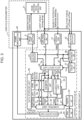
Fig. 2 is a block diagram illustrating the configuration of a biological activity detection unit and a motion assisting unit; -
Fig. 3 is a block diagram illustrating an internal configuration of the motion assisting unit; -
Fig. 4 is a block diagram illustrating the configuration of a biological activity detection unit according to this embodiment; and -
Fig. 5 is a block diagram illustrating the configuration of the biological activity detection unit according to another embodiment. - An embodiment of the present invention will be explained below in detail with reference to the drawings.
-
Fig. 1 illustrates a heartrehabilitation support apparatus 1 as a whole according to this embodiment and the heartrehabilitation support apparatus 1 is designed to support functional recovery of a subject's heart after a cardiovascular disease treatment by using a recumbent-type bicycle ergometer 2 which imparts an arbitrary exercise load according to a pedaling motion of a subject in a seated state, a biologicalactivity detection unit 3 which detects the subject's biological activities, and amotion assisting unit 4 which assists the subject's pedaling motion. - The
bicycle ergometer 2 includes: asaddle part 5 for the subject to be seated on, pedals 6 for pedaling by the subject; acrank 7 to which the pedals are attached; adrive unit 8 that imparts load torque as the exercise load upon rotations of thecrank 7 according to the subject's pedaling motion; and adisplay unit 9 that displays the exercise load and exercise time as well as a rotation position and rotational speed of thecrank 7. - The biological
activity detection unit 3 includes, as illustrated inFig. 2 , a cardiaccondition detection unit 10 that detects the subject's heart rate and electrocardiogram changes, and an arterialblood measurement unit 11 that measures the subject's pulse rate and blood oxygen saturation degree. - The
motion assisting unit 4 includes: a biologicalsignal detection unit 12 that detects a biological signal from the subject's lower limb parts; avoluntary control unit 13 that performs voluntary control of the load torque of thedrive unit 8 for thebicycle ergometer 2 so as to generate running torque and a rotational speed of thecrank 7 according to the subject's intention on the basis of the biological signal detected by the biologicalsignal detection unit 12; anautonomous control unit 14 that performs autonomous control of the load torque of thedrive unit 8 so as to generate assisting power for the subject's pedaling motion on the basis of a rotation angle of thecrank 7; and an optimumtorque adjustment unit 15 that adjusts a hybrid ratio of the voluntary control by thevoluntary control unit 13 and the autonomous control by theautonomous control unit 14 on the basis of the detection and measurement results by the cardiaccondition detection unit 10 and the arterialblood measurement unit 11 for the biologicalactivity detection unit 3. - Furthermore, the display unit (synchronous video display unit) 9 for the
bicycle ergometer 2 is provided within a field of vision of the subject in a state of being seated on thebicycle ergometer 2 and is designed to display a video which changes in synchronization with the pedaling motion of the subject in accordance with the control by themotion assisting unit 4. - Consequently, the subject can continuously perform the exercise for the functional recovery of their heart in a positive mood (by recognizing a sense of accomplishment) while experiencing, through a visual check, an exercise amount (a state of progress) by the pedaling motion.
- In the heart
rehabilitation support apparatus 1, thebicycle ergometer 2 includes, as illustrated inFig. 3 : a drive unit 9 (Fig. 1 ) that imparts an assisting force to the subject (the force to generate the running torque which acts on the crank 7); apower amplification unit 20 that drives thedrive unit 9; and a crank rotationstate detection unit 21 that detects the running torque, the rotational speed, and the rotation angle of thecrank 7. - The
motion assisting unit 4 includes: a jointangle estimation unit 22 that estimates an angular displacement θ of each joint of the subject (corresponding to each of a knee joint and a hip joint) on the basis of the rotation angle of thecrank 7; a biological signal detection unit 12 (Fig. 1 ) that detects a muscle potential (biological signal) according to muscle strength generated by the subject; and a relativeforce detection unit 23 that detects a relative force (ΔF) which acts on themotion assisting unit 4, that is, a force which is relatively defined by the relation between the force generated by thedrive unit 8 and the subject's muscle strength. - The
motion assisting unit 4 in this embodiment controls the assisting force by using a bio-electrical signal (BES: Bio-Electrical Signal) that is a command signal as a biological signal from an upper central nervous system, which is generated in the form of an electric potential on a muscle surface via a spinal cord. - Furthermore, the
motion assisting unit 4 includes a control apparatus 24 that controls driving of thedrive unit 8 through thepower amplification unit 20. The control apparatus 24 includes a drivingtorque estimation unit 25, a joint torque estimation unit 26, a muscletorque estimation unit 27, adata input unit 28, adata storage unit 29, acalibration unit 30, aparameter identification unit 31, a control unit (including thevoluntary control unit 13, theautonomous control unit 14, and the optimumtorque adjustment unit 15 mentioned earlier) 32, adata output unit 33, a condition quantification unit 34, and asignal processing unit 35. - The driving
torque estimation unit 25 estimates driving torque (Te) generated by thedrive unit 8. For example, it is possible to apply a device which estimates the driving torque (Te) by detecting an electric current value supplied to thedrive unit 8 and multiplying this electric current value by a torque constant specific to thedrive unit 8. - The joint torque estimation unit 26 estimates a joint moment (ΔT) around each joint of the subject from the difference between a value obtained by multiplying relative force data (ΔF) detected by the relative
force detection unit 23 by a preset constant and the driving torque estimation data (Te). Since a resultant force of the driving torque (Te) of thedrive unit 8 and muscle torque (Tm) of the subject acts as a joint moment (ΔT) on the subject's legs, it enables the subject to move their legs with smaller muscle strength than the case where the subject does not perform the pedaling motion. - The muscle
torque estimation unit 27 estimates the muscle torque (Tm) by the subject's muscle strength on the basis of the driving torque estimation data (Te) estimated by the drivingtorque estimation unit 25 and the joint moment estimation data (ΔT) which is estimated by the joint torque estimation unit 26. Incidentally, the muscle torque (Tm) is found in order to enable parameter identification even under the circumstance where the subject generates the muscle strength; and it is advantageous for the case where the parameter identification is performed when the subject is in a motion state. - The
data input unit 28 is an input interface for detection data from the various kinds of detection units for themotion assisting unit 4 and estimation data from the various kinds of estimation units. Thedata storage unit 29 stores data which are required for various kinds of arithmetic processing by the control apparatus 24. - The
parameter identification unit 31 is configured so that: a target motion equation is configured in a computing environment by using a motion equation (Mi) and known parameters (Pk) which are read from thedata storage unit 29; and a driving torque estimated value (Te), a joint torque estimated value (ΔT), and a joint angle θ from thedata input unit 28 can be applied to that motion equation. - Under this circumstance, the motion equation (Mi) is to configure a motion equation of the entire system composed of the
motion assisting unit 4 and the subject; and on the other hand, the known parameters (Pk) are composed of dynamics parameters such as weights of the respective parts of themotion assisting unit 4, moment of inertia around the joints, a viscosity coefficient, and a Coulomb's friction coefficient. - The parameter identification unit 31: executes the arithmetic processing in consideration of driving torque estimation data (T'), joint data (θ) and joint moment data (ΔT), and further the muscle torque (Tm) which have been read; identifies unknown dynamics parameters (Pu) such as the weights of the respective parts of the subject, the moment of inertia around each joint, the viscosity coefficient, and the Coulomb's friction coefficient; and repeats the identification a plurality of number of times (for example, 10 times), averages the parameters, and sends them to the
control unit 32. - The
calibration unit 30 reads a ratio (Tm/EMG) of the estimated muscle torque (Tm) to a muscle potential (EMG) from thedata input unit 28 and a specified set gain (Gs) from thedata storage unit 29; and if the set gain (Gs) is outside a permissible error range (Ea), thecalibration unit 30 calculates corrected muscle potential data (EMG') by correcting the muscle potential data (EMG) and thereby causes a ratio (Tm/EMG') of the muscle torque (Tm) to the corrected muscle potential (EMG') to become substantially equal to the set gain (Gs). - As a result, it is possible to prevent the situation where identification accuracy of the subject's unknown parameters (Pu) may degrade; and it is also possible to prevent the situation where the assisting force generated by the
drive unit 8 may become excessively small or excessively large. - The
control unit 32 is configured to be capable of reading control method data (Ci) from thedata storage unit 29, the driving torque estimated value (Te), the joint torque estimated value (ΔT), and the joint angle θ from thedata input unit 28, an identification parameter (Pi) from theparameter identification unit 31, and the corrected muscle potential (EMG') from thecalibration unit 30. - Furthermore, the
control unit 32 configures a specified control means in the computing environment by using the control method data (Ci) and reflects the driving torque estimated value (Te), the joint torque estimated value (ΔT), the joint angle θ, the identification parameter (Pi), and the muscle potential (EMG') in this control means, thereby making it possible to send out a control signal Ur for controlling driving of thedrive unit 8. - The
data output unit 33 is an output interface for transmitting the control signal Ur from thecontrol unit 32 to thepower amplification unit 20. Thepower amplification unit 20 is to drive thedrive unit 8 according to the control signal Ur from thedata output unit 28. - Furthermore, the
motion assisting unit 4 is designed to control the assisting force based on impedance adjustments so as to solve natural control hindrances attributable to restrictions by physical properties of the apparatus itself, that is, viscoelasticity around the joints and the inertia of thecrank 7. Specifically speaking, themotion assisting unit 4 enhances an assisting rate for the waling motion and reduces a sense of discomfort felt by the subject by calculating parameters for the joints and compensating for the moment of inertia, the viscosity, and the elasticity by using an actuator of thedrive unit 8. - Consequently, the
motion assisting unit 4 can indirectly change and adjust properties of the subject by changing properties of the entire system which is constituted by the unit itself plus the subject. For example, it becomes possible to demonstrate the ability, which the subject originally has, to perform agile motions such as reflexes to the maximum extent by adjusting the driving torque so that any influence by inertia terms and viscous friction terms of the entire system can be suppressed. Furthermore, it is also possible to suppress any influence by inertia terms and viscous friction terms of the subject themselves and cause the subject to walk faster than their original cycle and perform motions more smoothly (with less viscous frictions) than before wearing the unit. - Furthermore, the
motion assisting unit 4 in a state attached to the subject can cause theparameter identification unit 31 to identify the dynamics parameters specific to the subject and cause the control apparatus 24 to control thedrive unit 8 on the basis of the motion equation to which the identified dynamics parameters are applied, so that it is possible to exhibit the advantageous effects according to the control method used by the control apparatus 24 regardless of variation factors such as individual differences between subjects and the relevant subject's physical condition. - Furthermore, since the
drive unit 8 can be controlled by the control apparatus 24 on the basis of the motion equation to which the muscle torque (Tm) estimated by the muscletorque estimation unit 27 is also applied, the dynamics parameters can be identified even in the state where the muscle strength is generated from the subject; and the above-described advantageous effects can be exhibited without requiring the subject wait during waiting time to identify the dynamics parameters. - Since the
calibration unit 30 which adjusts a mutual gain between the muscle potential (EMG) detected by the biologicalsignal detection unit 12 and the muscle torque (Tm) detected by the muscletorque estimation unit 27 so that the mutual gain becomes the set gain (Gs) which is previously set, it is possible to prevent the situation where poor sensitivity or excessive sensitivity may occur in the detection result from the biologicalsignal detection unit 12. - As a result, it is possible to prevent the situation where the identification accuracy of the subject's dynamics parameters may degrade; and it is also possible to prevent the situation where the assisting force generated by the
drive unit 8 may become excessively small or excessively large. Additionally, themotion assisting unit 4 in this embodiment: can perform calibration even in the state where the muscle strength is generated from the subject; and does not require the subject to wait during the waiting time to perform the calibration. - Since at least either one of gravity compensation and inertia compensation which use the dynamics parameters identified by the
parameter identification unit 31 can be applied to the control apparatus 24, it is possible to prevent the situation where the weight of the apparatus itself may become a burden on the subject; and it is possible to prevent the inertia of the apparatus itself from giving a sense of discomfort to the subject when the apparatus operates. - The condition quantification unit 34 for the control apparatus 24 converts an activity state of the musculoskeletal system and a transmission state of the peripheral nervous system around the joints to quantitative musculoskeletal system data and nervous system data on the basis of a muscle potential signal and a neural transmission signal as well as physical quantities around the joints which are supplied from the
control unit 32. - The physical quantities around the joints include, for example: results of the parameter identification of at least one or more of the muscle strength which occur at muscles and skeleton, an articular range of motion, movable speed, and reaction rate of each joint, autonomous control properties with respect to disturbances, and the moment of inertia, mass, and center of gravity of the crank; impedance adjustment results (viscous property by frictions) of the joint system including flexor muscles and extensor muscles; and electric physical quantity (command signal).
- The
signal processing unit 35 has a wireless communication function and transmits the musculoskeletal system data and the nervous system data, which are supplied from thecontrol unit 32, to a data terminal device (which is not illustrated in the drawing) via a communication network. With the data terminal device, the musculoskeletal system data and the nervous system data are integrally managed with respect to each subject by an administrative server and are designed to be used for medical treatments and treatment methods. - Accordingly, the
drive unit 8 imparts the driving force to assist the subject's voluntary motions and the driven state of thedrive unit 8 is reflected in the musculoskeletal system data and the nervous system data, so that it becomes possible, on the basis of the above-reflected results, to quantitatively evaluate to what degree the voluntary control will influence an active state of the subject's musculoskeletal system and a connection state of the subject's central nervous system and peripheral nervous system. - Incidentally, the
control unit 32 performs voluntary control of the load torque of thedrive unit 8 for thebicycle ergometer 2 to generate the running torque and the rotational speed of thecrank 7 according to the subject's intention and performs autonomous control of the load torque of thedrive unit 8 for thebicycle ergometer 2 to generate the assisting power for the subject's pedaling motion as described later. Then, thecontrol unit 32 is designed to control the pedaling motion by adjusting the hybrid ratio of the voluntary control and the autonomous control on the basis of the outputs from the biologicalactivity detection unit 3 so as to not increase the subject's exercise load excessively. - The biological
activity detection unit 3 includes, as means for detecting the subject's biological information as illustrated inFig. 4 , a plurality ofbiological electrode groups 40 as an electrocardiogram sensor and a respiratory sensor, and apulse oximeter 41 as an SpO2 sensor. The plurality ofbiological electrode groups 40 are attached to the subject's right and left wrists, left ankle, and precordial region and electromotive forces of the subject's heart at these attached regions are input as electric signals to the electrocardiacsignal generation unit 42. - The pulse oximeter 41: emits red light and/or infrared light, lets them transmit through a patient's specified region (such as a fingertip or a toe), and finds a ratio of oxygenated hemoglobin to total hemoglobin in arterial blood on the basis of the transmitted light (reflected light); and measures arterial oxygen saturation (SpO2 value) and a pulse rate by detecting changes in absorbance in synchronization with pulses of the arterial blood.
- The heart
rate measurement unit 43 identifies the position of a ORS wave in the subject's electrocardiogram according to the electrocardiac signal obtained from the electrocardiacsignal generation unit 42 and calculates an average value of a heart beat interval (R-R interval) of the subject in immediate several seconds on the basis of the position of the identified ORS wave. Then, the heartrate measurement unit 43 calculates the subject's heart rate on the basis of the average value of the heart beat interval (R-R interval) and generates data indicating the heart rate. - The
SpO2 extraction unit 44 extracts data indicating the measurement result of the arterial oxygen saturation on the basis of outputs from thepulse oximeter 41. The pulserate extraction unit 45 extracts data indicating the pulse rate on the basis of the outputs from thepulse oximeter 41. - The waveform display control unit 46: obtains waveform information representing the subject's electrocardiographic waveform and SpO2 waveform by applying specified display processing including synchronization processing to an electrocardiac signal, which is input from the electrocardiac
signal generation unit 42, and an output signal which is input from thepulse oximeter 41; and outputs the waveform information to thedisplay unit 9 for thebicycle ergometer 2. - Accordingly, the biological
activity detection unit 3 inputs the subject's heart rate and electrocardiogram changes, which are obtained from the electrocardiacsignal generation unit 42 and the heartrate measurement unit 43 as the cardiaccondition detection unit 10, and the subject's pulse rate and blood oxygen saturation degree, which are obtained from theSpO2 extraction unit 44 and the pulserate extraction unit 45 as the arterialblood measurement unit 11, to the optimumtorque adjustment unit 15 for themotion assisting unit 4. - Consequently, the
motion assisting unit 4 can adjust the hybrid ratio of the voluntary control and the autonomous control on the basis of the subject's heart rate and electrocardiogram changes and the subject's pulse rate and blood oxygen saturation degree. - With the heart
rehabilitation support apparatus 1 in this embodiment having the above-described configuration, while the subject uses thebicycle ergometer 2 and performs the pedaling motion in the seated state, themotion assisting unit 4 performs the voluntary control of the load torque of thedrive unit 8 so as to generate the running torque and the rotational speed of thecrank 7 according to the subject's intention and performs the autonomous control of the load torque of thedrive unit 8 so as to generate the assisting power for the subject's pedaling motion on the basis of the rotation angle of thecrank 7. - Under this circumstance, the motion assisting unit 4: adjusts the hybrid ratio of the voluntary control and the autonomous control with respect to the load torque of the
drive unit 8 on the basis of the subject's heart rate and electrocardiogram changes and the subject's pulse rate and blood oxygen saturation degree which are obtained from the biologicalactivity detection unit 3; and can thereby perform the exercise for the functional recovery of the heart while always adjusting the exercise load to an optimum state according to the subject's heart condition without letting the subject excessively increase the exercise load according to the pedaling motion of thebicycle ergometer 2. - Furthermore, the
motion assisting unit 4 controls the load torque of thedrive unit 8, by means of the voluntary control and the autonomous control respectively, so that the subject's heart rate is always maintained within an appropriate range. Therefore, when the subject is performing the pedaling motion and their own heart rate is about to exceed the appropriate range, themotion assisting unit 4 can perform the control to increase the load torque of thedrive unit 8 and reduce the pedal rotation frequency at the same time; and when the subject's own heart rate is about to fall below the appropriate range, themotion assisting unit 4 can perform the control to decrease the load torque of thedrive unit 8 and increase the crank rotational frequency at the same time. - As a result, the subject can do exercise for the functional recovery of their heart without making the heart rate increase or decrease excessively unconsciously.
- Incidentally, the aforementioned embodiment has described the case where the biological
activity detection unit 3 having the configuration illustrated inFig. 4 is applied; however, the present invention is not limited to this example and a concentration of carbon dioxides contained in the subject's exhaled gas may be detected and the detection result may be added to the adjustments of the hybrid ratio of the voluntary control and the autonomous control. - Referring to
Fig. 5 , a biologicalactivity detection unit 50 includes a respiratorysignal generation unit 51 and respirationrate measurement unit 52 for detecting the subject's respiration rate, and an exhalation detection unit 53 for detecting the concentration of carbon dioxides contained in the exhaled gas of each breath of the subject. - The respiratory
signal generation unit 51 passes a small high-frequency current between thebiological electrode groups 40 which are attached to the right and left sides of the precordial region, measures an electric potential difference between them, and generates a respiratory signal by recognizing movements of the subject's thorax as changes in impedance of the thorax on the basis of the measurement results. - The respiration
rate measurement unit 52 measures the subject's respiration rate on the basis of the respiratory signal obtained from the respiratorysignal generation unit 51 and generates data indicating the respiration rate. The waveformdisplay control unit 46 obtains waveform information representing the subject's respiration waveform by applying specified display processing including synchronization processing to the respiratory signal, which is input from the respiratorysignal generation unit 51, and outputs the waveform information to thedisplay unit 9 for thebicycle ergometer 2. - The exhalation detection unit 53 includes: a gas sensor 57 composed of a light-emitting
unit 55 which emits infrared light to a passage for making the subject's respiratory air flow through amouthpiece 54 held between the subject's teeth, and a light-receivingunit 56 which receives the infrared light emitted by the light-emittingunit 55; and ameasurement unit 58 that measures the concentration of carbon dioxides contained in the subject's exhaled gas on the basis of an electric signal which is output from the gas sensor. - Generally, when the subject does exercise to gradually increase the exercise intensity, the degree of exercise intensity is judged with reference to an anaerobic metabolism threshold (AT: Anaerobic Threshold) which is a change point at which oxygen supply to the muscles makes a transition from a sufficient state to an insufficient state. Specifically speaking, the anaerobic metabolism threshold: corresponds to the upper limit exercise intensity of aerobic exercise because it means that the oxygen is sufficient; and coincides with a physiological change point where, for example, an increase in an amount of carbon dioxide emission exceeds an increase in an amount of oxygen intake.
- Accordingly, with the heart
rehabilitation support apparatus 1, the biologicalactivity detection unit 50 detects the carbon dioxides contained in the subject's exhaled gas, so that themotion assisting unit 4 thereby judges the degree of the exercise intensity according to the subject's anaerobic metabolism threshold and adjusts the hybrid ratio of the voluntary control and the autonomous control together with the subject's heart rate and electrocardiogram changes and the subject's pulse rate and blood oxygen saturation degree. - Consequently, with the heart
rehabilitation support apparatus 1, the subject can do the exercise for the functional recovery of the heart by always adjusting the exercise load to the optimum state according to the subject's heart condition without excessively increasing the exercise load according to the pedaling motion of thebicycle ergometer 2. - Furthermore, this embodiment has described the case where the bicycle ergometer as illustrated in
Fig. 1 is applied as the instrument for imparting an arbitrary exercise load to the subject; however, the present invention is not limited to this example and stationary-type or elliptical (cross-trainer) type bicycle ergometers other than the recumbent type may be used or a rowing machine and/or a treadmill may be further applied as long as the functional recovery of the subject's heart after the cardiovascular disease treatment can be supported by the subject's exercise. -
- 1:
- heart rehabilitation support apparatus
- 2:
- bicycle ergometer
- 3, 50:
- biological activity detection unit
- 4:
- motion assisting unit
- 5:
- saddle part
- 6:
- pedals
- 7:
- crank
- 8:
- drive unit
- 9:
- display unit
- 10:
- cardiac condition detection unit
- 11:
- arterial blood measurement unit
- 12:
- biological signal detection unit
- 13:
- voluntary control unit
- 14:
- autonomous control unit
- 15:
- optimum torque adjustment unit
- 20:
- power amplification unit
- 21:
- crank rotation state detection unit
- 22:
- joint angle estimation unit
- 23:
- relative force detection unit
- 24:
- control apparatus
- 25:
- driving torque estimation unit
- 26:
- joint torque estimation unit
- 27:
- muscle torque estimation unit
- 28:
- data input unit
- 29:
- data storage unit
- 30:
- calibration unit
- 31:
- parameter identification unit
- 32:
- control unit
- 33:
- data output unit
- 34:
- condition quantification unit
- 35:
- signal processing unit
- 40:
- bioelectrode
- 41:
- pulse oximeter
- 42:
- electrocardiac signal generation unit
- 43:
- heart rate measurement unit
- 44:
- SpO2 extraction unit
- 45:
- pulse rate extraction unit
- 46:
- waveform display control unit
- 51:
- respiratory signal generation unit
- 52:
- respiration rate measurement unit
- 53:
- exhalation detection unit
- 54:
- mouthpiece
- 55:
- light-emitting unit
- 56:
- light-receiving unit
- 57:
- gas sensor
- 58:
- measurement unit
Claims (6)
- A heart rehabilitation support apparatus (1) for supporting functional recovery of a heart of a subject after a cardiovascular disease treatment by using an instrument configured to impart an arbitrary exercise load according to a pedaling motion of the subject in a seated state, the heart rehabilitation support apparatus comprising:a drive unit (8) that imparts load torque as the exercise load upon rotation of a crank to which pedals to be pushed by the subject is attached in the instrument;a biological signal detection unit (3) that detects a biological signal from lower limb parts of the subject;a cardiac condition detection unit (10) that detects a heart rate and an electrocardiogram change of the subject;a voluntary control unit (13) that performs voluntary control of the load torque of the drive unit so as to generate running torque and a rotational speed according to an intention of the subject on the basis of the biological signal detected by the biological signal detection unit;an autonomous control unit (14) that performs autonomous control of the load torque of the drive unit so as to generate assisting power for the pedaling motion of the subject on the basis of a rotation angle of the crank;an arterial blood measurement unit (11) that measures a pulse rate and a blood oxygen saturation degree of the subject; andan optimum torque adjustment unit (15) that adjusts a hybrid ratio of the voluntary control by the voluntary control unit and the autonomous control by the autonomous control unit on the basis of detection and measurement results by the cardiac condition detection unit and the arterial blood measurement unit;wherein the voluntary control unit and the autonomous control unit are respectively configured to control the load torque of the drive unit so that the heart rate of the subject is always maintained within an appropriate range;wherein the heart rehabilitation support apparatus is configured to decrease a pedal rotation frequency at the same time as increasing the load torque of the drive unit when the subject's heart rate is about to exceed the appropriate range while the subject is performing the pedaling motion; andwherein the heart rehabilitation support apparatus is configured to increase a crank rotational frequency at the same time as decreasing the load torque of the drive unit when the subject's heart rate is about to fall below the appropriate range.
- The heart rehabilitation support apparatus according to claim 1, further comprising an exhalation detection unit (53) that detects a concentration of carbon dioxides contained in an exhaled gas of the subject,
wherein the optimum torque adjustment unit adjusts the hybrid ratio of the voluntary control by the voluntary control unit and the autonomous control by the autonomous control unit on the basis of detection and measurement results by the cardiac condition detection unit, the arterial blood measurement unit, and the exhalation detection unit. - The heart rehabilitation support apparatus according to any one of claims 1 or 2, further comprising a synchronous video display unit (9) that is provided within a field of vision of the subject in the seated state at the instrument and displays a video which changes in synchronization with the pedaling motion of the subject.
- A storage medium comprising instructions which, when executed, cause a heart rehabilitation support apparatus according to claim 1 to carry out the steps of a heart rehabilitation support method for supporting functional recovery of a heart of a subject after a cardiovascular disease treatment, the method including the steps of:
imparting load torque as the exercise load upon rotation of a crank to which pedals to be pushed by the subject is attached in the instrument,performing voluntary control of the load torque of the drive unit on the basis of a biological signal detected from lower limb parts of the subject so as to generate running torque and a rotational speed according to an intention of the subject;performing autonomous control of the load torque of the drive unit on the basis of a rotation angle of the crank so as to generate assisting power for the pedaling motion of the subject, andadjusting a hybrid ratio of the voluntary control and the autonomous control on the basis of detection results of a heart rate and an electrocardiogram change of the subject and measurement results of a pulse rate and a blood oxygen saturation degree of the subject;performing the voluntary control and the autonomous control of the load torque of the drive unit so that the heart rate of the subject is always maintained within an appropriate range;decreasing a pedal rotation frequency at the same time as increasing the load torque of the drive unit when the subject's heart rate is about to exceed the appropriate range while the subject is performing the pedaling motion; andincreasing a crank rotational frequency at the same time as decreasing the load torque of the drive unit when the subject's heart rate is about to fall below the appropriate range. - The storage medium according to claim 4,
wherein the method further includes adjusting the hybrid ratio of the voluntary control and the autonomous control on the basis of a detection result of a concentration of carbon dioxides contained in an exhaled gas of the subject, the detection results of the heart rate and the electrocardiogram change of the subject, and the measurement results of the pulse rate and the blood oxygen saturation degree of the subject. - The storage medium according to any one of claims 4 or 5,
wherein the method further includes displaying a video which changes in synchronization with the pedaling motion of the subject within a field of vision of the subject in the seated state at the instrument.
Applications Claiming Priority (2)
| Application Number | Priority Date | Filing Date | Title |
|---|---|---|---|
| JP2019014243A JP7181801B2 (en) | 2019-01-30 | 2019-01-30 | Cardiac rehabilitation support device and its control program |
| PCT/JP2020/003561 WO2020158904A1 (en) | 2019-01-30 | 2020-01-30 | Heart rehabilitation assistance device and heart rehabilitation assistance method |
Publications (3)
| Publication Number | Publication Date |
|---|---|
| EP3919036A1 EP3919036A1 (en) | 2021-12-08 |
| EP3919036A4 EP3919036A4 (en) | 2022-10-12 |
| EP3919036B1 true EP3919036B1 (en) | 2024-12-25 |
Family
ID=71841048
Family Applications (1)
| Application Number | Title | Priority Date | Filing Date |
|---|---|---|---|
| EP20749386.7A Active EP3919036B1 (en) | 2019-01-30 | 2020-01-30 | Heart rehabilitation assistance device and heart rehabilitation assistance method |
Country Status (4)
| Country | Link |
|---|---|
| US (1) | US12472402B2 (en) |
| EP (1) | EP3919036B1 (en) |
| JP (1) | JP7181801B2 (en) |
| WO (1) | WO2020158904A1 (en) |
Families Citing this family (43)
| Publication number | Priority date | Publication date | Assignee | Title |
|---|---|---|---|---|
| US12029940B2 (en) | 2019-03-11 | 2024-07-09 | Rom Technologies, Inc. | Single sensor wearable device for monitoring joint extension and flexion |
| US11801423B2 (en) | 2019-05-10 | 2023-10-31 | Rehab2Fit Technologies, Inc. | Method and system for using artificial intelligence to interact with a user of an exercise device during an exercise session |
| US11904207B2 (en) | 2019-05-10 | 2024-02-20 | Rehab2Fit Technologies, Inc. | Method and system for using artificial intelligence to present a user interface representing a user's progress in various domains |
| US11833393B2 (en) | 2019-05-15 | 2023-12-05 | Rehab2Fit Technologies, Inc. | System and method for using an exercise machine to improve completion of an exercise |
| US11071597B2 (en) | 2019-10-03 | 2021-07-27 | Rom Technologies, Inc. | Telemedicine for orthopedic treatment |
| US12224052B2 (en) | 2019-10-03 | 2025-02-11 | Rom Technologies, Inc. | System and method for using AI, machine learning and telemedicine for long-term care via an electromechanical machine |
| US11955221B2 (en) | 2019-10-03 | 2024-04-09 | Rom Technologies, Inc. | System and method for using AI/ML to generate treatment plans to stimulate preferred angiogenesis |
| US12087426B2 (en) | 2019-10-03 | 2024-09-10 | Rom Technologies, Inc. | Systems and methods for using AI ML to predict, based on data analytics or big data, an optimal number or range of rehabilitation sessions for a user |
| US11955220B2 (en) | 2019-10-03 | 2024-04-09 | Rom Technologies, Inc. | System and method for using AI/ML and telemedicine for invasive surgical treatment to determine a cardiac treatment plan that uses an electromechanical machine |
| US20230245750A1 (en) | 2019-10-03 | 2023-08-03 | Rom Technologies, Inc. | Systems and methods for using elliptical machine to perform cardiovascular rehabilitation |
| US12605613B2 (en) | 2022-05-04 | 2026-04-21 | Rom Technologies, Inc. | Systems and methods for using smart exercise devices to perform cardiovascular rehabilitation |
| US11756666B2 (en) | 2019-10-03 | 2023-09-12 | Rom Technologies, Inc. | Systems and methods to enable communication detection between devices and performance of a preventative action |
| US11923065B2 (en) | 2019-10-03 | 2024-03-05 | Rom Technologies, Inc. | Systems and methods for using artificial intelligence and machine learning to detect abnormal heart rhythms of a user performing a treatment plan with an electromechanical machine |
| US12347543B2 (en) | 2019-10-03 | 2025-07-01 | Rom Technologies, Inc. | Systems and methods for using artificial intelligence to implement a cardio protocol via a relay-based system |
| US11961603B2 (en) | 2019-10-03 | 2024-04-16 | Rom Technologies, Inc. | System and method for using AI ML and telemedicine to perform bariatric rehabilitation via an electromechanical machine |
| US11955222B2 (en) | 2019-10-03 | 2024-04-09 | Rom Technologies, Inc. | System and method for determining, based on advanced metrics of actual performance of an electromechanical machine, medical procedure eligibility in order to ascertain survivability rates and measures of quality-of-life criteria |
| US12555667B2 (en) | 2019-10-03 | 2026-02-17 | Rom Technologies, Inc. | Systems and methods for using AI/ML and for cardiac and pulmonary treatment via an electromechanical machine related to urologic disorders and antecedents and sequelae of certain urologic surgeries |
| US11955223B2 (en) | 2019-10-03 | 2024-04-09 | Rom Technologies, Inc. | System and method for using artificial intelligence and machine learning to provide an enhanced user interface presenting data pertaining to cardiac health, bariatric health, pulmonary health, and/or cardio-oncologic health for the purpose of performing preventative actions |
| US12020800B2 (en) | 2019-10-03 | 2024-06-25 | Rom Technologies, Inc. | System and method for using AI/ML and telemedicine to integrate rehabilitation for a plurality of comorbid conditions |
| US11830601B2 (en) | 2019-10-03 | 2023-11-28 | Rom Technologies, Inc. | System and method for facilitating cardiac rehabilitation among eligible users |
| US12548656B2 (en) | 2019-10-03 | 2026-02-10 | Rom Technologies, Inc. | System and method for an enhanced patient user interface displaying real-time measurement information during a telemedicine session |
| US12230381B2 (en) | 2019-10-03 | 2025-02-18 | Rom Technologies, Inc. | System and method for an enhanced healthcare professional user interface displaying measurement information for a plurality of users |
| US12020799B2 (en) | 2019-10-03 | 2024-06-25 | Rom Technologies, Inc. | Rowing machines, systems including rowing machines, and methods for using rowing machines to perform treatment plans for rehabilitation |
| US12176089B2 (en) | 2019-10-03 | 2024-12-24 | Rom Technologies, Inc. | System and method for using AI ML and telemedicine for cardio-oncologic rehabilitation via an electromechanical machine |
| US12230382B2 (en) | 2019-10-03 | 2025-02-18 | Rom Technologies, Inc. | Systems and methods for using artificial intelligence and machine learning to predict a probability of an undesired medical event occurring during a treatment plan |
| US12420143B1 (en) | 2019-10-03 | 2025-09-23 | Rom Technologies, Inc. | System and method for enabling residentially-based cardiac rehabilitation by using an electromechanical machine and educational content to mitigate risk factors and optimize user behavior |
| US12469587B2 (en) | 2019-10-03 | 2025-11-11 | Rom Technologies, Inc. | Systems and methods for assigning healthcare professionals to remotely monitor users performing treatment plans on electromechanical machines |
| US11915816B2 (en) | 2019-10-03 | 2024-02-27 | Rom Technologies, Inc. | Systems and methods of using artificial intelligence and machine learning in a telemedical environment to predict user disease states |
| US12380984B2 (en) | 2019-10-03 | 2025-08-05 | Rom Technologies, Inc. | Systems and methods for using artificial intelligence and machine learning to generate treatment plans having dynamically tailored cardiac protocols for users to manage a state of an electromechanical machine |
| US11887717B2 (en) | 2019-10-03 | 2024-01-30 | Rom Technologies, Inc. | System and method for using AI, machine learning and telemedicine to perform pulmonary rehabilitation via an electromechanical machine |
| US11915815B2 (en) | 2019-10-03 | 2024-02-27 | Rom Technologies, Inc. | System and method for using artificial intelligence and machine learning and generic risk factors to improve cardiovascular health such that the need for additional cardiac interventions is mitigated |
| US12062425B2 (en) | 2019-10-03 | 2024-08-13 | Rom Technologies, Inc. | System and method for implementing a cardiac rehabilitation protocol by using artificial intelligence and standardized measurements |
| US11826613B2 (en) | 2019-10-21 | 2023-11-28 | Rom Technologies, Inc. | Persuasive motivation for orthopedic treatment |
| US12367960B2 (en) | 2020-09-15 | 2025-07-22 | Rom Technologies, Inc. | System and method for using AI ML and telemedicine to perform bariatric rehabilitation via an electromechanical machine |
| US20240286005A1 (en) * | 2020-11-25 | 2024-08-29 | Saga Holographic, Inc. | Exercise apparatus with integrated holographic display |
| JP7642359B2 (en) | 2020-12-17 | 2025-03-10 | フクダ電子株式会社 | Drive control device, exercise load device, cardiopulmonary exercise load test device, and cardiac rehabilitation device |
| JP6990333B1 (en) | 2021-05-14 | 2022-02-03 | 株式会社ファンケル | Optimal exercise intensity estimation method, training method, exercise instruction device, and optimal exercise intensity estimation system |
| JP7303595B1 (en) | 2021-11-25 | 2023-07-05 | 株式会社CaTe | Program, information processing device, and information processing method |
| US12551744B2 (en) * | 2022-08-04 | 2026-02-17 | University Of Florida Research Foundation, Incorporated | Method, apparatus, and system for motorized rehabilitative cycling |
| US20240399210A1 (en) * | 2023-06-02 | 2024-12-05 | Metabrain Technology Pte. Ltd. | Cardiopulmonary rehabilitation assistance system |
| CN116943096A (en) * | 2023-07-21 | 2023-10-27 | 深圳市美林医疗器械科技有限公司 | A kind of rehabilitation management exercise method |
| WO2025220094A1 (en) * | 2024-04-16 | 2025-10-23 | 三菱電機エンジニアリング株式会社 | Exercise load control device and exercise load control method |
| JP7553739B1 (en) * | 2024-04-18 | 2024-09-18 | 株式会社ファンケル | PULSE RATE ESTIMATION METHOD, TRAINING METHOD, EXERCISE INSTRUCTION DEVICE, AND PULSE RATE ESTIMATION SYSTEM |
Family Cites Families (21)
| Publication number | Priority date | Publication date | Assignee | Title |
|---|---|---|---|---|
| US4463764A (en) * | 1981-09-29 | 1984-08-07 | Medical Graphics Corporation | Cardiopulmonary exercise system |
| JP3929230B2 (en) | 2000-04-26 | 2007-06-13 | 三菱電機エンジニアリング株式会社 | Exercise therapy equipment |
| JP2003231491A (en) * | 2002-02-08 | 2003-08-19 | Sunstar Eng Inc | Power-assisted bicycle providing aerobic exercise |
| JP4178186B2 (en) * | 2003-08-21 | 2008-11-12 | 国立大学法人 筑波大学 | Wearable motion assist device, control method for wearable motion assist device, and control program |
| JP4200492B2 (en) * | 2004-03-11 | 2008-12-24 | 国立大学法人 筑波大学 | Wearable motion assist device |
| JP4178187B2 (en) * | 2005-01-26 | 2008-11-12 | 国立大学法人 筑波大学 | Wearable motion assist device and control program |
| JP4138814B2 (en) * | 2006-04-06 | 2008-08-27 | 本田技研工業株式会社 | Exercise management system |
| JP2009015449A (en) | 2007-07-02 | 2009-01-22 | Sony Corp | Biological information sharing system, biological information expression device, and biological information expression method |
| US8562488B2 (en) * | 2009-10-05 | 2013-10-22 | The Cleveland Clinic Foundation | Systems and methods for improving motor function with assisted exercise |
| US8177688B2 (en) * | 2009-10-12 | 2012-05-15 | Madonna Rehabilitation Hospital | Rehabilitation and exercise machine |
| GB2485216A (en) * | 2010-11-08 | 2012-05-09 | Ultra Motor Ltd | Electric pedal cycle with exercise program |
| CA2828420C (en) * | 2011-03-02 | 2018-05-01 | University Of Tsukuba | Gait training device and gait training system |
| TWI458521B (en) * | 2012-10-19 | 2014-11-01 | Ind Tech Res Inst | Smart bike and operation method thereof |
| US9675512B2 (en) * | 2013-03-14 | 2017-06-13 | Elwha Llc | Leg locomotion devices |
| JP2016016233A (en) * | 2014-07-10 | 2016-02-01 | 国立大学法人 筑波大学 | Biosignal measurement device, biosignal measurement method, body-worn movement assist device, and movement assist method |
| US20160023081A1 (en) * | 2014-07-16 | 2016-01-28 | Liviu Popa-Simil | Method and accessories to enhance riding experience on vehicles with human propulsion |
| JP5786072B1 (en) * | 2014-07-18 | 2015-09-30 | 嗣久 波多野 | Exercise test system |
| JP6601609B2 (en) | 2015-02-27 | 2019-11-06 | 国立大学法人京都大学 | Cardiac rehabilitation support information system |
| WO2016178393A1 (en) * | 2015-05-01 | 2016-11-10 | Cyberdyne株式会社 | Model-animal functional-improvement evaluation apparatus and nerve-cell culturing apparatus |
| US11298284B2 (en) | 2017-02-10 | 2022-04-12 | Woodway Usa, Inc. | Motorized recumbent therapeutic and exercise device |
| JP6805022B2 (en) | 2017-02-23 | 2020-12-23 | 三菱電機エンジニアリング株式会社 | Exercise therapy equipment and methods for identifying anaerobic thresholds |
-
2019
- 2019-01-30 JP JP2019014243A patent/JP7181801B2/en active Active
-
2020
- 2020-01-30 WO PCT/JP2020/003561 patent/WO2020158904A1/en not_active Ceased
- 2020-01-30 EP EP20749386.7A patent/EP3919036B1/en active Active
- 2020-01-30 US US17/425,537 patent/US12472402B2/en active Active
Also Published As
| Publication number | Publication date |
|---|---|
| WO2020158904A1 (en) | 2020-08-06 |
| JP7181801B2 (en) | 2022-12-01 |
| US20220118315A1 (en) | 2022-04-21 |
| US12472402B2 (en) | 2025-11-18 |
| EP3919036A4 (en) | 2022-10-12 |
| EP3919036A1 (en) | 2021-12-08 |
| JP2020120910A (en) | 2020-08-13 |
Similar Documents
| Publication | Publication Date | Title |
|---|---|---|
| US12472402B2 (en) | Heart rehabilitation support apparatus and heart rehabilitation support method | |
| JP6742196B2 (en) | Life activity detection device and life activity detection system | |
| EP2519905B1 (en) | Biofeedback for program guidance in pulmonary rehabilitation | |
| CN111013104B (en) | Respiratory muscle training system under exercise state and method of using the same | |
| EP3202320B1 (en) | System for reliably coordinating musculoskeletal and cardiovascular hemodynamics | |
| US8608622B2 (en) | Systems and methods for improving motor function with assisted exercise | |
| CN102695490B (en) | Systems and methods for improving motor function using assisted exercise | |
| JP2009516565A (en) | Walking exercise equipment including exercise prescription function | |
| KR20110118879A (en) | Active rehabilitation device and system | |
| JP7333537B2 (en) | Program, information processing device, and information processing method | |
| Basla et al. | Enhancing walking efficiency of adolescents with neurological impairments using an exosuit for ambulatory activities of daily living | |
| Hollmann et al. | Methods for measurement of physical fitness and training recommendations in studies on humans | |
| US20250339733A1 (en) | Information processing apparatus, method, and system | |
| RU2844825C1 (en) | Method for assessing and correcting the functional state of a person (versions) and a system for implementing said method | |
| US20250090404A1 (en) | Function improvement assistance apparatus and function improvement assistance method | |
| Ajayi | On treadmill automation and physiological control systems | |
| JP2025115427A (en) | Information processing device, method, program, and system | |
| WO2025220304A1 (en) | Pulse rate estimation method, training method, exercise instruction device, and pulse rate estimation system | |
| Weng | Monitoring and Control of the Cardiovascular System During Indoor Exercise | |
| Krogshede | Statistical Parametric Mapping: SEMG analysis of shoulder muscle | |
| Annoni | THE IMPACT OF PHYSICAL FITNESS AND PHYSICAL ACTIVITY LEVEL ON BIOMECHANICAL AND METABOLIC PARAMETERS OF TREADMILL WALKING IN NORMAL-WEIGHT AND OBESE YOUNG ADULTS. |
Legal Events
| Date | Code | Title | Description |
|---|---|---|---|
| STAA | Information on the status of an ep patent application or granted ep patent |
Free format text: STATUS: THE INTERNATIONAL PUBLICATION HAS BEEN MADE |
|
| PUAI | Public reference made under article 153(3) epc to a published international application that has entered the european phase |
Free format text: ORIGINAL CODE: 0009012 |
|
| STAA | Information on the status of an ep patent application or granted ep patent |
Free format text: STATUS: REQUEST FOR EXAMINATION WAS MADE |
|
| 17P | Request for examination filed |
Effective date: 20210816 |
|
| AK | Designated contracting states |
Kind code of ref document: A1 Designated state(s): AL AT BE BG CH CY CZ DE DK EE ES FI FR GB GR HR HU IE IS IT LI LT LU LV MC MK MT NL NO PL PT RO RS SE SI SK SM TR |
|
| DAV | Request for validation of the european patent (deleted) | ||
| DAX | Request for extension of the european patent (deleted) | ||
| A4 | Supplementary search report drawn up and despatched |
Effective date: 20220909 |
|
| RIC1 | Information provided on ipc code assigned before grant |
Ipc: A63B 21/00 20060101ALI20220905BHEP Ipc: A61B 5/1455 20060101ALI20220905BHEP Ipc: A61B 5/091 20060101ALI20220905BHEP Ipc: A61B 5/024 20060101ALI20220905BHEP Ipc: A61H 1/02 20060101AFI20220905BHEP |
|
| STAA | Information on the status of an ep patent application or granted ep patent |
Free format text: STATUS: EXAMINATION IS IN PROGRESS |
|
| 17Q | First examination report despatched |
Effective date: 20240301 |
|
| GRAP | Despatch of communication of intention to grant a patent |
Free format text: ORIGINAL CODE: EPIDOSNIGR1 |
|
| STAA | Information on the status of an ep patent application or granted ep patent |
Free format text: STATUS: GRANT OF PATENT IS INTENDED |
|
| INTG | Intention to grant announced |
Effective date: 20240925 |
|
| GRAS | Grant fee paid |
Free format text: ORIGINAL CODE: EPIDOSNIGR3 |
|
| GRAA | (expected) grant |
Free format text: ORIGINAL CODE: 0009210 |
|
| STAA | Information on the status of an ep patent application or granted ep patent |
Free format text: STATUS: THE PATENT HAS BEEN GRANTED |
|
| AK | Designated contracting states |
Kind code of ref document: B1 Designated state(s): AL AT BE BG CH CY CZ DE DK EE ES FI FR GB GR HR HU IE IS IT LI LT LU LV MC MK MT NL NO PL PT RO RS SE SI SK SM TR |
|
| REG | Reference to a national code |
Ref country code: GB Ref legal event code: FG4D |
|
| REG | Reference to a national code |
Ref country code: CH Ref legal event code: EP |
|
| REG | Reference to a national code |
Ref country code: DE Ref legal event code: R096 Ref document number: 602020043681 Country of ref document: DE |
|
| REG | Reference to a national code |
Ref country code: IE Ref legal event code: FG4D |
|
| REG | Reference to a national code |
Ref country code: LT Ref legal event code: MG9D |
|
| PG25 | Lapsed in a contracting state [announced via postgrant information from national office to epo] |
Ref country code: HR Free format text: LAPSE BECAUSE OF FAILURE TO SUBMIT A TRANSLATION OF THE DESCRIPTION OR TO PAY THE FEE WITHIN THE PRESCRIBED TIME-LIMIT Effective date: 20241225 |
|
| PG25 | Lapsed in a contracting state [announced via postgrant information from national office to epo] |
Ref country code: FI Free format text: LAPSE BECAUSE OF FAILURE TO SUBMIT A TRANSLATION OF THE DESCRIPTION OR TO PAY THE FEE WITHIN THE PRESCRIBED TIME-LIMIT Effective date: 20241225 |
|
| PG25 | Lapsed in a contracting state [announced via postgrant information from national office to epo] |
Ref country code: BG Free format text: LAPSE BECAUSE OF FAILURE TO SUBMIT A TRANSLATION OF THE DESCRIPTION OR TO PAY THE FEE WITHIN THE PRESCRIBED TIME-LIMIT Effective date: 20241225 |
|
| PG25 | Lapsed in a contracting state [announced via postgrant information from national office to epo] |
Ref country code: NO Free format text: LAPSE BECAUSE OF FAILURE TO SUBMIT A TRANSLATION OF THE DESCRIPTION OR TO PAY THE FEE WITHIN THE PRESCRIBED TIME-LIMIT Effective date: 20250325 |
|
| PG25 | Lapsed in a contracting state [announced via postgrant information from national office to epo] |
Ref country code: LV Free format text: LAPSE BECAUSE OF FAILURE TO SUBMIT A TRANSLATION OF THE DESCRIPTION OR TO PAY THE FEE WITHIN THE PRESCRIBED TIME-LIMIT Effective date: 20241225 Ref country code: GR Free format text: LAPSE BECAUSE OF FAILURE TO SUBMIT A TRANSLATION OF THE DESCRIPTION OR TO PAY THE FEE WITHIN THE PRESCRIBED TIME-LIMIT Effective date: 20250326 |
|
| PG25 | Lapsed in a contracting state [announced via postgrant information from national office to epo] |
Ref country code: RS Free format text: LAPSE BECAUSE OF FAILURE TO SUBMIT A TRANSLATION OF THE DESCRIPTION OR TO PAY THE FEE WITHIN THE PRESCRIBED TIME-LIMIT Effective date: 20250325 |
|
| REG | Reference to a national code |
Ref country code: NL Ref legal event code: MP Effective date: 20241225 |
|
| PG25 | Lapsed in a contracting state [announced via postgrant information from national office to epo] |
Ref country code: NL Free format text: LAPSE BECAUSE OF FAILURE TO SUBMIT A TRANSLATION OF THE DESCRIPTION OR TO PAY THE FEE WITHIN THE PRESCRIBED TIME-LIMIT Effective date: 20241225 |
|
| REG | Reference to a national code |
Ref country code: AT Ref legal event code: MK05 Ref document number: 1753579 Country of ref document: AT Kind code of ref document: T Effective date: 20241225 |
|
| PG25 | Lapsed in a contracting state [announced via postgrant information from national office to epo] |
Ref country code: SM Free format text: LAPSE BECAUSE OF FAILURE TO SUBMIT A TRANSLATION OF THE DESCRIPTION OR TO PAY THE FEE WITHIN THE PRESCRIBED TIME-LIMIT Effective date: 20241225 |
|
| PG25 | Lapsed in a contracting state [announced via postgrant information from national office to epo] |
Ref country code: PL Free format text: LAPSE BECAUSE OF FAILURE TO SUBMIT A TRANSLATION OF THE DESCRIPTION OR TO PAY THE FEE WITHIN THE PRESCRIBED TIME-LIMIT Effective date: 20241225 |
|
| PG25 | Lapsed in a contracting state [announced via postgrant information from national office to epo] |
Ref country code: ES Free format text: LAPSE BECAUSE OF FAILURE TO SUBMIT A TRANSLATION OF THE DESCRIPTION OR TO PAY THE FEE WITHIN THE PRESCRIBED TIME-LIMIT Effective date: 20241225 |
|
| PG25 | Lapsed in a contracting state [announced via postgrant information from national office to epo] |
Ref country code: IS Free format text: LAPSE BECAUSE OF FAILURE TO SUBMIT A TRANSLATION OF THE DESCRIPTION OR TO PAY THE FEE WITHIN THE PRESCRIBED TIME-LIMIT Effective date: 20250425 |
|
| PG25 | Lapsed in a contracting state [announced via postgrant information from national office to epo] |
Ref country code: PT Free format text: LAPSE BECAUSE OF FAILURE TO SUBMIT A TRANSLATION OF THE DESCRIPTION OR TO PAY THE FEE WITHIN THE PRESCRIBED TIME-LIMIT Effective date: 20250428 |
|
| PG25 | Lapsed in a contracting state [announced via postgrant information from national office to epo] |
Ref country code: EE Free format text: LAPSE BECAUSE OF FAILURE TO SUBMIT A TRANSLATION OF THE DESCRIPTION OR TO PAY THE FEE WITHIN THE PRESCRIBED TIME-LIMIT Effective date: 20241225 |
|
| PG25 | Lapsed in a contracting state [announced via postgrant information from national office to epo] |
Ref country code: RO Free format text: LAPSE BECAUSE OF FAILURE TO SUBMIT A TRANSLATION OF THE DESCRIPTION OR TO PAY THE FEE WITHIN THE PRESCRIBED TIME-LIMIT Effective date: 20241225 Ref country code: AT Free format text: LAPSE BECAUSE OF FAILURE TO SUBMIT A TRANSLATION OF THE DESCRIPTION OR TO PAY THE FEE WITHIN THE PRESCRIBED TIME-LIMIT Effective date: 20241225 |
|
| PG25 | Lapsed in a contracting state [announced via postgrant information from national office to epo] |
Ref country code: SK Free format text: LAPSE BECAUSE OF FAILURE TO SUBMIT A TRANSLATION OF THE DESCRIPTION OR TO PAY THE FEE WITHIN THE PRESCRIBED TIME-LIMIT Effective date: 20241225 |
|
| PG25 | Lapsed in a contracting state [announced via postgrant information from national office to epo] |
Ref country code: CZ Free format text: LAPSE BECAUSE OF FAILURE TO SUBMIT A TRANSLATION OF THE DESCRIPTION OR TO PAY THE FEE WITHIN THE PRESCRIBED TIME-LIMIT Effective date: 20241225 |
|
| REG | Reference to a national code |
Ref country code: CH Ref legal event code: PL |
|
| PG25 | Lapsed in a contracting state [announced via postgrant information from national office to epo] |
Ref country code: SE Free format text: LAPSE BECAUSE OF FAILURE TO SUBMIT A TRANSLATION OF THE DESCRIPTION OR TO PAY THE FEE WITHIN THE PRESCRIBED TIME-LIMIT Effective date: 20241225 |
|
| PG25 | Lapsed in a contracting state [announced via postgrant information from national office to epo] |
Ref country code: LU Free format text: LAPSE BECAUSE OF NON-PAYMENT OF DUE FEES Effective date: 20250130 Ref country code: MC Free format text: LAPSE BECAUSE OF FAILURE TO SUBMIT A TRANSLATION OF THE DESCRIPTION OR TO PAY THE FEE WITHIN THE PRESCRIBED TIME-LIMIT Effective date: 20241225 |
|
| REG | Reference to a national code |
Ref country code: DE Ref legal event code: R097 Ref document number: 602020043681 Country of ref document: DE |
|
| PG25 | Lapsed in a contracting state [announced via postgrant information from national office to epo] |
Ref country code: DK Free format text: LAPSE BECAUSE OF FAILURE TO SUBMIT A TRANSLATION OF THE DESCRIPTION OR TO PAY THE FEE WITHIN THE PRESCRIBED TIME-LIMIT Effective date: 20241225 |
|
| PG25 | Lapsed in a contracting state [announced via postgrant information from national office to epo] |
Ref country code: BE Free format text: LAPSE BECAUSE OF NON-PAYMENT OF DUE FEES Effective date: 20250131 |
|
| PG25 | Lapsed in a contracting state [announced via postgrant information from national office to epo] |
Ref country code: CH Free format text: LAPSE BECAUSE OF NON-PAYMENT OF DUE FEES Effective date: 20250131 |
|
| REG | Reference to a national code |
Ref country code: BE Ref legal event code: MM Effective date: 20250131 |
|
| PLBE | No opposition filed within time limit |
Free format text: ORIGINAL CODE: 0009261 |
|
| STAA | Information on the status of an ep patent application or granted ep patent |
Free format text: STATUS: NO OPPOSITION FILED WITHIN TIME LIMIT |
|
| 26N | No opposition filed |
Effective date: 20250926 |
|
| PG25 | Lapsed in a contracting state [announced via postgrant information from national office to epo] |
Ref country code: FR Free format text: LAPSE BECAUSE OF NON-PAYMENT OF DUE FEES Effective date: 20250225 |
|
| PG25 | Lapsed in a contracting state [announced via postgrant information from national office to epo] |
Ref country code: IE Free format text: LAPSE BECAUSE OF NON-PAYMENT OF DUE FEES Effective date: 20250130 |
|
| PGFP | Annual fee paid to national office [announced via postgrant information from national office to epo] |
Ref country code: GB Payment date: 20260119 Year of fee payment: 7 |
|
| PGFP | Annual fee paid to national office [announced via postgrant information from national office to epo] |
Ref country code: DE Payment date: 20260122 Year of fee payment: 7 |
|
| PGFP | Annual fee paid to national office [announced via postgrant information from national office to epo] |
Ref country code: IT Payment date: 20260126 Year of fee payment: 7 |