EP3919010B1 - Chirurgische zugangsvorrichtung mit verstellbarem kanülenabschnitt - Google Patents
Chirurgische zugangsvorrichtung mit verstellbarem kanülenabschnitt Download PDFInfo
- Publication number
- EP3919010B1 EP3919010B1 EP21177618.2A EP21177618A EP3919010B1 EP 3919010 B1 EP3919010 B1 EP 3919010B1 EP 21177618 A EP21177618 A EP 21177618A EP 3919010 B1 EP3919010 B1 EP 3919010B1
- Authority
- EP
- European Patent Office
- Prior art keywords
- circular
- ridges
- adjustable
- circular ridges
- adjacent
- Prior art date
- Legal status (The legal status is an assumption and is not a legal conclusion. Google has not performed a legal analysis and makes no representation as to the accuracy of the status listed.)
- Active
Links
Images


Classifications
-
- A—HUMAN NECESSITIES
- A61—MEDICAL OR VETERINARY SCIENCE; HYGIENE
- A61B—DIAGNOSIS; SURGERY; IDENTIFICATION
- A61B17/00—Surgical instruments, devices or methods
- A61B17/34—Trocars; Puncturing needles
- A61B17/3417—Details of tips or shafts, e.g. grooves, expandable, bendable; Multiple coaxial sliding cannulas, e.g. for dilating
- A61B17/3421—Cannulas
-
- A—HUMAN NECESSITIES
- A61—MEDICAL OR VETERINARY SCIENCE; HYGIENE
- A61B—DIAGNOSIS; SURGERY; IDENTIFICATION
- A61B17/00—Surgical instruments, devices or methods
- A61B17/34—Trocars; Puncturing needles
- A61B17/3417—Details of tips or shafts, e.g. grooves, expandable, bendable; Multiple coaxial sliding cannulas, e.g. for dilating
-
- A—HUMAN NECESSITIES
- A61—MEDICAL OR VETERINARY SCIENCE; HYGIENE
- A61B—DIAGNOSIS; SURGERY; IDENTIFICATION
- A61B17/00—Surgical instruments, devices or methods
- A61B17/28—Surgical forceps
- A61B17/29—Forceps for use in minimally invasive surgery
- A61B2017/2901—Details of shaft
- A61B2017/2905—Details of shaft flexible
-
- A—HUMAN NECESSITIES
- A61—MEDICAL OR VETERINARY SCIENCE; HYGIENE
- A61B—DIAGNOSIS; SURGERY; IDENTIFICATION
- A61B17/00—Surgical instruments, devices or methods
- A61B17/28—Surgical forceps
- A61B17/29—Forceps for use in minimally invasive surgery
- A61B2017/2901—Details of shaft
- A61B2017/2908—Multiple segments connected by articulations
-
- A—HUMAN NECESSITIES
- A61—MEDICAL OR VETERINARY SCIENCE; HYGIENE
- A61B—DIAGNOSIS; SURGERY; IDENTIFICATION
- A61B17/00—Surgical instruments, devices or methods
- A61B17/34—Trocars; Puncturing needles
- A61B17/3417—Details of tips or shafts, e.g. grooves, expandable, bendable; Multiple coaxial sliding cannulas, e.g. for dilating
- A61B17/3421—Cannulas
- A61B2017/3443—Cannulas with means for adjusting the length of a cannula
Definitions
- the present disclosure relates to a surgical access device. More particularly, the present disclosure relates to surgical access devices having adjustable cannula portions.
- Endoscopic and laparoscopic minimally invasive procedures have been used for introducing medical devices inside a patient and for viewing portions of the patient's anatomy.
- a surgeon may insert a rigid or flexible endoscope inside the patient to physically engage with the anatomical site.
- a trocar assembly typically includes a cannula and an obturator.
- the cannula remains in place for use during the laparoscopic procedure, and the obturator includes a tip for penetrating body tissue.
- endoscopic surgical procedures surgery is performed in any hollow organ or tissue of the body through a small incision or through a narrow endoscopic tube (e.g., a cannula) inserted through a small entrance wound in the skin.
- endoscopic procedures surgical operations in the abdomen are performed through small incisions (usually about 0.5 to about 1.5 cm). Laparoscopic and endoscopic procedures often require the surgeon to act on organs, tissues, and vessels at varying distances from the incision.
- an adjustable trocar assembly that is configured to provide flexibility of depth within a surgical site.
- the present invention provides an adjustable trocar assembly as claimed in claim 1 appended hereto, the assembly including a housing configured to facilitate insertion of one or more surgical tools into a patient's body and an elongated tubular member extending distally from the housing and defining a longitudinal axis. Further embodiments are defined by the dependent claims.
- the elongated tubular member includes a channel configured to facilitate passage of surgical instruments through the elongated tubular member, an adjustable portion configured to facilitate axial movement of the elongated tubular member, a collar of fixed diameter, and a rim of fixed diameter equal to the diameter of the collar.
- the adjustable portion is defined by a plurality of adjacent circular ridges centered along the longitudinal axis of the elongated tubular member.
- Each circular ridge of the plurality of circular ridges is operably coupled to one or more adjacent circular ridges of the plurality of circular ridges by a flexible material interconnecting adjacent circular ridges.
- the collar may be positioned along the elongated tubular member where the channel transitions into the adjustable portion and the rim is disposed on the distal end of the adjustable portion.
- a small portion of excess material defines a fold in each circular ridge of the plurality of circular ridges.
- the fold is configured to collapse inward and facilitate partial insertion of one circular ridge of the plurality of circular ridges into a proximally adjacent circular ridge of the plurality of circular ridges.
- each circular ridge of the plurality of circular ridges may be configured to be inserted into the distal end of the proximally adjacent circular ridge of the plurality of circular ridges, and the distal end of each circular ridge of the plurality of circular ridges may be configured to receive the proximal end of the distally adjacent circular ridge of the plurality of circular ridges when in a retracted state.
- each circular ridge of the plurality of circular ridges may be configured to be separated from the proximal end of the distally adjacent circular ridge of the plurality of circular ridges by a length of a fold when in an extended state.
- the collar and the rim may be made from a rigid material.
- Each pair of adj acent circular ridges may interact independently from all other non-adjacent circular ridges, such that the adjustable portion can be partially extended or partially retracted.
- Adjacent circular ridges of the plurality of circular ridges are interconnected by a layer of thin and flexible material.
- the method includes introducing one or more surgical tools into a channel defined by an elongated tubular member, wherein the elongated tubular member includes a plurality of adjacent circular ridges coupled to one another by a flexible material defining an adjustable portion, and wherein a collar of fixed diameter and a rim of fixed diameter cooperate to ensure that axial uniformity is maintained along the adjustable portion of the elongated tubular member.
- the method further includes moving the one or more surgical tools through the channel and the adjustable portion until the distal ends of the one or more surgical tools engage the rim of the adjustable portion.
- the method may further include extending the adjustable portion toward a target site in a patient's body by exerting a force on the rim in the distal direction until the separation between the distal ends of at least one pair of adj acent of circular ridges, of the plurality of circular ridges, is increased. Additionally, the method includes retracting the adjustable portion away from the target site in the patient's body by exerting a force on the rim in the proximal direction, until at the proximal end of at least one circular ridge of the plurality of circular ridges is partially inserted into the distal end of an adjacent circular ridge of the plurality of circular ridges.
- distal refers to that portion of the instrument, or component thereof which is farther from the user while the term “proximal” refers to that portion of the instrument or component thereof which is closer to the user.
- the surgical access device includes a trocar assembly which may be employed during surgery (e.g., laparoscopic surgery) and may, in various aspects, provide for the sealed access of laparoscopic surgical instruments into an insufflated body cavity, such as the abdominal cavity.
- the step of the present disclosure includes a cannula and an obturator insertable therethrough.
- the cannula and obturator are separate components but are capable of being selectively connected together.
- the obturator may be inserted into and through the cannula until the handle of the obturator engages, e.g., selectively locks into, a proximal housing of the cannula.
- the trocar assembly is employed to tunnel through an anatomical structure, e.g., the abdominal wall, either by making a new passage through the structure or by passing through an existing opening through the structure.
- the obturator is removed, leaving the cannula in place in the structure, e.g., in the incision created by the trocar assembly.
- the proximal housing of the cannula may include seals or valves that prevent the escape of insufflation gases from the body cavity, while also allowing surgical instruments to be inserted into the body cavity. Further details of a surgical access device including a cannula and an obturator are described in U.S. Patent No. 10,022,149 to Holsten et al., issued on July 17, 2018 , and U.S. Patent Application Publication No. 2018/0085145 to Okoniewski et al., filed on November 13, 2017 .
- the adjustable trocar assembly 100 includes a cannula 200, and an obturator 300.
- the obturator 300 is insertable through a channel 210 defined by an elongated tubular member 220 of cannula 200, which defines a longitudinal axis X-X. Additionally, obturator 300 is selectively engageable with or attachable to cannula 200. More particularly, a proximal portion 302 of obturator 300 is selectively engageable with or attachable to a proximal portion or housing 202 of cannula 200.
- a distal end 310 of obturator 300 is advanced into tissue "T" to create or enlarge an incision or opening in tissue "T” ( FIGS. 4A-C ).
- a distal end 230 of cannula 200 can be used to create or enlarge an opening in tissue "T," without the use of an obturator, for instance.
- the adjustable portion 400 of the present disclosure is positionable on cannula 200, and is configured to provide a wider range of motion in which cannula 200 can be extended or retracted with respect to the tissue "T.”
- the adjustable portion 400 is comprised of a plurality of adjacent concentric circular ridges 410 centered along the longitudinal axis X-X of the elongated tubular member 220. Adj acent concentric circular ridges 410 of elongated tubular member 220 are interconnected by a thin layer of flexible material that defines an internal surface 420 and an external surface 430.
- Each of the plurality of circular ridges 410 includes a proximal end 410a and a distal end 410b such that the radius of the proximal end 410a is less than the radius of the radius of the distal end 410b, as can be seen in FIG. 3D .
- the difference in radius corresponds to a difference in circumference between the proximal end 410a and the distal end 410b, and creates a tapering effect along the external surface 430 between adjacent ridges 400, as can be seen in FIGS 3A-3C .
- each of the plurality of circular ridges 410 allows for the proximal end 410a to be partially inserted into the proximally adjacent circular ridge 410, such that the minimum axial radius of the internal surface 420 never decreases below the radius of the proximal end 410a.
- the tapering effect ensures that a minimum axial radius exists along the internal surface 420 of the adjustable portion 400 regardless of whether adjustable portion 400 is retracted, extended, or unaltered, as can be seen in FIGS 3A-3C .
- adjustable portion 400 has a uniform inner and outer diameter.
- this axial uniformity along internal surface 420 allows for any standard sized obturator 300 to be inserted through channel 210 regardless of whether the adjustable portion 400 is retracted, extended, or unaltered.
- each circular ridge of the plurality of circular ridges 410 includes a fold 415 made of a small portion of excess material from the thin and flexible material used to interconnect adjacent circular ridges 410.
- the internal surface 420 of the fold 415 is configured to fold/collapse in on itself between the adjacent circular ridges 410 when the adjustable portion 400 is compressed/retracted, as shown in FIGS. 2A and 3A .
- the fold 415 is configured to unfold and to extend distally outward to increase the separation between adjacent circular ridges 410.
- the adjustable trocar assembly 100 is inserted through a patient's abdominal wall to provide the obturator 300 with access to area being targeted for treatment.
- obturator 300 may need to be inserted farther into the body cavity.
- the length of obturator 300 being used will also vary according to this need and the length of the channel 210 through which obturator 300 is inserted will also need to be variable.
- the surgeon would need to remove the cannula in use and replace it with a longer cannula.
- Adjustable portion 400 provides benefit of variable length without a need to exchange one cannula for another, and without adding any risk of complications to the procedure. Instead of removing one piece of equipment from the patient's body and inserting another, the adjustable portion 400 of the elongated tubular member 220 can simply be extended as needed. Additionally, the variable length of adjustable portion 400 can be easily adjusted to match the thickness of a patient's tissue layer(s).
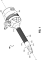
- FIG. 1 shows another aspect of the adjustable trocar assembly 100, where the elongated tubular member 220 further includes a collar 215 positioned along the elongated tubular member 220 at the point where the channel 210 transitions into the adjustable portion 400 of elongated tubular member 220, and a rim 225 positioned at the distal end of the elongated member 220. Together the collar 215 and rim 225 cooperate to ensure that axial uniformity is maintained along the elongated tubular member 220. Unlike the retractable and extendable circular ridges 410 positioned in between the collar 215 and the rim 225, the collar 215 and rim 225 are rigid structures that cannot extend or retract. Instead, both the collar 215 and the rim 225 define rings of equal radii configured to ensure that a minimum axial radius throughout the length of adjustable portion 400.
- each of the plurality of circular ridges 410 is configured to be partially inserted into the distal end 410b of the proximally adjacent circular ridge 410, and that the distal end 410b of each of the plurality of circular ridges 410 is configured to receive the proximal end 410a of the distally adjacent circular ridge 410 when in the retracted state.
- the rigidity of collar 215 allows the collar 215 to act as a brace that can receive the proximal end 410a of the proximal-most circular ridge 410 of the adjustable portion 400.
- the second most proximal circular ridge 410 can then receive the proximal end 410a of the third most proximal circular ridge 410 and so on until eventually all of the adjacent circular ridges 410 have been partially inserted and the adjustable portion 400 is in a fully retracted state.
- the tapering effect between adjacent circular ridges 410 requires an initial rigid form to support the first partial insertion of one ridge 410 into another.
- the collar 215 provides that initial rigid support structure that is relied upon by all subsequent adjacent circular ridges 410.
- the collar 215 defines the minimum axial radius and by extension ensures axial uniformity along the elongated tubular member 220.
- the rim 225 disposed on the distal end of elongated member 220 acts as a brace for the final circular ridge 410 and provides a well-defined stopping point that can independently maintain its shape and rigid form.
- rim 225 ensures that the distal-most circular ridge 410 maintains its shape and as such also ensures axial uniformity along the elongated tubular member 220. Additionally, the rim 225 acts as a guide for any surgical instruments inserted therethrough by ensuring that upon exiting the rim said surgical instruments are facing in the direction of the area being targeted for treatment.
- a semi-rigid material can also be used to interconnect the plurality of circular ridges 410, such that each pair of adjacent circular ridges 410 can interact completely independently of all other non-adjacent circular ridges 410 comprising the adjustable portion 400. This independence can facilitate partial extension and retraction of the adjustable portion 400, regardless of the rigidity of the collar 215.
Landscapes
- Health & Medical Sciences (AREA)
- Surgery (AREA)
- Life Sciences & Earth Sciences (AREA)
- Biomedical Technology (AREA)
- Nuclear Medicine, Radiotherapy & Molecular Imaging (AREA)
- Engineering & Computer Science (AREA)
- Pathology (AREA)
- Heart & Thoracic Surgery (AREA)
- Medical Informatics (AREA)
- Molecular Biology (AREA)
- Animal Behavior & Ethology (AREA)
- General Health & Medical Sciences (AREA)
- Public Health (AREA)
- Veterinary Medicine (AREA)
- Surgical Instruments (AREA)
Claims (6)
- Einstellbare Trokaranordnung (100), umfassend:ein Gehäuse (202), das so konfiguriert ist, dass es das Einführen eines oder mehrerer chirurgischer Werkzeuge in den Körper eines Patienten erleichtert; undein langgestrecktes röhrenförmiges Element (220), das sich distal von dem Gehäuse erstreckt und eine Längsachse definiert, wobei das langgestreckte röhrenförmige Element einschließt:einen Kanal (210), der so konfiguriert ist, dass er den Durchgang von chirurgischen Instrumenten durch das langgestreckte röhrenförmige Element erleichtert;einen einstellbaren Abschnitt (400), der so konfiguriert ist, dass er die axiale Ausdehnung oder das axiale Zurückziehen des langgestreckten röhrenförmigen Elements erleichtert, wobei der einstellbare Abschnitt durch eine Vielzahl benachbarter ausfahrbarer und zurückziehbarer kreisförmiger Stege (410) definiert ist, die entlang der Längsachse des langgestreckten röhrenförmigen Elements zentriert sind, wobei jeder der kreisförmigen Stege (410) ein proximales Ende (41 0a) und ein distales Ende (41 0b) einschließt, wobei der Radius des proximalen Endes kleiner ist als der Radius des distalen Endes, um einen Verjüngungseffekt entlang einer Außenfläche (430) zwischen benachbarten Rippen zu erzeugen, um zu ermöglichen, dass das proximale Ende (410a) teilweise in den proximal benachbarten kreisförmigen Steg (410) eingeführt wird, so dass der minimale axiale Radius der Innenfläche (420) des rohrförmigen Elements niemals unter den Radius des proximalen Endes (410a) jedes kreisförmigen Stegs (410) abnimmt;einen Kragen (215) mit festem Durchmesser; undeinen Rand (225) mit festem Durchmesser, der gleich dem Durchmesser des Kragens ist; dadurch gekennzeichnet, dass jeder der kreisförmigen Stege (410) des einstellbaren Abschnitts mit einem oder mehreren benachbarten kreisförmigen Stegen der Vielzahl von kreisförmigen Stegen durch ein flexibles Material, das benachbarte kreisförmige Stege miteinander verbindet, funktionsfähig gekoppelt ist, wobei jeder kreisförmige Steg eine Falte (415) aufweist, die durch einen Überschuss eines kleinen Abschnitts des flexiblen Materials gebildet wird, wobei die Falte so konfiguriert ist, dass sie zwischen benachbarten kreisförmigen Stegen nach innen kollabiert, um ein teilweises Einführen eines kreisförmigen Stegs in einen benachbarten kreisförmigen Steg während des Zurückziehens des einstellbaren Abschnitts (400) zu erleichtern.
- Einstellbare Trokaranordnung nach Anspruch 1, wobei der Kragen (215) entlang des länglichen röhrenförmigen Elements (220) positioniert ist, wo der Kanal (210) in den einstellbaren Abschnitt (400) übergeht, und der Rand (225) an dem distalen Ende des einstellbaren Abschnitts angeordnet ist.
- Einstellbare Trokaranordnung nach einem der vorhergehenden Ansprüche, wobei das proximale Ende (410a) jedes kreisförmigen Steges (410) der Vielzahl von kreisförmigen Stegen so konfiguriert ist, dass es in das distale Ende (410b) des proximal benachbarten kreisförmigen Steges der Vielzahl von kreisförmigen Stegen eingeführt wird, und das distale Ende (410b) jedes kreisförmigen Steges der Vielzahl von kreisförmigen Stegen so konfiguriert ist, dass es das proximale Ende (410a) des distal benachbarten kreisförmigen Steges der Vielzahl von kreisförmigen Stegen aufnimmt, wenn es sich in einem zurückgezogenen Zustand befindet.
- Einstellbare Trokaranordnung nach Anspruch 3, wobei das distale Ende (410b) jedes kreisförmigen Steges (410) der Vielzahl von kreisförmigen Stegen so konfiguriert ist, dass es von dem proximalen Ende (410a) des distal benachbarten kreisförmigen Steges der Vielzahl von kreisförmigen Stegen durch eine Länge der Falte (415) getrennt ist, wenn es sich in einem ausgefahrenen Zustand befindet.
- Einstellbare Trokaranordnung nach Anspruch 2, wobei der Kragen (215) und der Rand (225) aus einem starren Material hergestellt sind.
- Einstellbare Trokaranordnung nach Anspruch 5, wobei jedes Paar benachbarter kreisförmiger Stege (410) durch ein halbstarres Material miteinander verbunden ist, so dass jedes Paar in der Lage ist, unabhängig von allen anderen nicht benachbarten kreisförmigen Stegen zu interagieren, so dass der einstellbare Abschnitt teilweise ausgefahren oder teilweise eingezogen werden kann.
Applications Claiming Priority (2)
| Application Number | Priority Date | Filing Date | Title |
|---|---|---|---|
| US202063034698P | 2020-06-04 | 2020-06-04 | |
| US17/320,370 US20210378703A1 (en) | 2020-06-04 | 2021-05-14 | Surgical access device including adjustable cannula portion |
Publications (2)
| Publication Number | Publication Date |
|---|---|
| EP3919010A1 EP3919010A1 (de) | 2021-12-08 |
| EP3919010B1 true EP3919010B1 (de) | 2024-12-11 |
Family
ID=76269661
Family Applications (1)
| Application Number | Title | Priority Date | Filing Date |
|---|---|---|---|
| EP21177618.2A Active EP3919010B1 (de) | 2020-06-04 | 2021-06-03 | Chirurgische zugangsvorrichtung mit verstellbarem kanülenabschnitt |
Country Status (2)
| Country | Link |
|---|---|
| US (1) | US20210378703A1 (de) |
| EP (1) | EP3919010B1 (de) |
Families Citing this family (1)
| Publication number | Priority date | Publication date | Assignee | Title |
|---|---|---|---|---|
| US11583315B2 (en) * | 2020-11-09 | 2023-02-21 | Covidien Lp | Surgical access device including variable length cannula |
Family Cites Families (10)
| Publication number | Priority date | Publication date | Assignee | Title |
|---|---|---|---|---|
| US8945058B2 (en) * | 2006-11-22 | 2015-02-03 | Applied Medical Resources Corporation | Trocar cannula with atraumatic tip |
| CA2631274A1 (en) * | 2007-05-18 | 2008-11-18 | Tyco Healthcare Group Lp | Flexible cannula with associated seal |
| US8517932B2 (en) * | 2009-12-11 | 2013-08-27 | Ethicon Endo-Surgery, Inc. | Methods and devices for providing access through tissue to a surgical site |
| US8414483B2 (en) * | 2009-12-11 | 2013-04-09 | Ethicon Endo-Surgery, Inc. | Methods and devices for providing access into a body cavity |
| DE102010044106A1 (de) * | 2010-11-18 | 2012-05-24 | Siemens Aktiengesellschaft | Instrumentensystem |
| US8491545B2 (en) * | 2011-08-25 | 2013-07-23 | Ethicon Endo-Surgery, Inc. | Surgical access device with adjustable cannula |
| US8496632B2 (en) * | 2011-08-25 | 2013-07-30 | Ethicon Endo-Surgery, Inc. | Surgical access device with adjustable cannula |
| EP2900153B1 (de) | 2012-09-28 | 2018-05-30 | Covidien LP | Optisches trokaranzeigesystem und vorrichtung |
| AU2016263013B2 (en) | 2015-05-15 | 2020-05-07 | Covidien Lp | Surgical access device |
| US10939937B2 (en) * | 2017-06-29 | 2021-03-09 | Ethicon Llc | Trocar with oblique needle insertion port and perpendicular seal latch |
-
2021
- 2021-05-14 US US17/320,370 patent/US20210378703A1/en active Pending
- 2021-06-03 EP EP21177618.2A patent/EP3919010B1/de active Active
Also Published As
| Publication number | Publication date |
|---|---|
| EP3919010A1 (de) | 2021-12-08 |
| US20210378703A1 (en) | 2021-12-09 |
Similar Documents
| Publication | Publication Date | Title |
|---|---|---|
| US8435174B2 (en) | Methods and devices for accessing a body cavity | |
| EP2502589B1 (de) | Zugang mit integrierter aufrollbarer Hülse | |
| EP0537758B1 (de) | Vorrichtung zum Festhalten von Gewebe zum Gebrauch mit Kanüle oder Trokar | |
| EP2630929B1 (de) | Wundschutz mit mehreren Teilen | |
| US8257251B2 (en) | Methods and devices for providing access into a body cavity | |
| US8414483B2 (en) | Methods and devices for providing access into a body cavity | |
| US8357088B2 (en) | Methods and devices for providing access into a body cavity | |
| EP2455023B1 (de) | Dichtungsanschluss mit anpassbarer Höhe | |
| CA3015089C (en) | Tools and methods for vaginal access | |
| JP6407977B2 (ja) | 生まれつきの開口用のアクセス器具 | |
| EP2324782A1 (de) | Anschlussbefestigungsvorrichtung | |
| EP2455027A2 (de) | Portalanordnung mit einstellbarer Höhe | |
| CN104717931B (zh) | 光学套管针可视化系统及设备 | |
| US10646690B2 (en) | Flexible surgical sheath and multi-part insertion cannula | |
| EP2166955B1 (de) | Vorrichtungen zum durchdringen einer anatomischen wand | |
| EP2465448A2 (de) | Integraler Schaumzugang | |
| US20210228198A1 (en) | Surgical access device with adjustable length | |
| EP0589452A1 (de) | Einrichtung zum Festhalten von Gewebe für den Gebrauch mit einer Kanülen- oder Trokareinheit | |
| EP3919010A1 (de) | Chirurgische zugangsvorrichtung mit verstellbarem kanülenabschnitt | |
| EP3957260A1 (de) | Flexible kanüle mit selektiver steifigkeit | |
| BR102012021227B1 (pt) | Portal de acesso único para videocirurgia | |
| WO2011072100A2 (en) | Methods and devices for providing access into a body cavity |
Legal Events
| Date | Code | Title | Description |
|---|---|---|---|
| PUAI | Public reference made under article 153(3) epc to a published international application that has entered the european phase |
Free format text: ORIGINAL CODE: 0009012 |
|
| STAA | Information on the status of an ep patent application or granted ep patent |
Free format text: STATUS: THE APPLICATION HAS BEEN PUBLISHED |
|
| AK | Designated contracting states |
Kind code of ref document: A1 Designated state(s): AL AT BE BG CH CY CZ DE DK EE ES FI FR GB GR HR HU IE IS IT LI LT LU LV MC MK MT NL NO PL PT RO RS SE SI SK SM TR |
|
| B565 | Issuance of search results under rule 164(2) epc |
Effective date: 20211004 |
|
| STAA | Information on the status of an ep patent application or granted ep patent |
Free format text: STATUS: REQUEST FOR EXAMINATION WAS MADE |
|
| 17P | Request for examination filed |
Effective date: 20220607 |
|
| RBV | Designated contracting states (corrected) |
Designated state(s): AL AT BE BG CH CY CZ DE DK EE ES FI FR GB GR HR HU IE IS IT LI LT LU LV MC MK MT NL NO PL PT RO RS SE SI SK SM TR |
|
| STAA | Information on the status of an ep patent application or granted ep patent |
Free format text: STATUS: EXAMINATION IS IN PROGRESS |
|
| 17Q | First examination report despatched |
Effective date: 20220915 |
|
| GRAP | Despatch of communication of intention to grant a patent |
Free format text: ORIGINAL CODE: EPIDOSNIGR1 |
|
| STAA | Information on the status of an ep patent application or granted ep patent |
Free format text: STATUS: GRANT OF PATENT IS INTENDED |
|
| RIC1 | Information provided on ipc code assigned before grant |
Ipc: A61B 17/29 20060101ALN20240620BHEP Ipc: A61B 17/34 20060101AFI20240620BHEP |
|
| INTG | Intention to grant announced |
Effective date: 20240703 |
|
| GRAS | Grant fee paid |
Free format text: ORIGINAL CODE: EPIDOSNIGR3 |
|
| GRAA | (expected) grant |
Free format text: ORIGINAL CODE: 0009210 |
|
| STAA | Information on the status of an ep patent application or granted ep patent |
Free format text: STATUS: THE PATENT HAS BEEN GRANTED |
|
| AK | Designated contracting states |
Kind code of ref document: B1 Designated state(s): AL AT BE BG CH CY CZ DE DK EE ES FI FR GB GR HR HU IE IS IT LI LT LU LV MC MK MT NL NO PL PT RO RS SE SI SK SM TR |
|
| REG | Reference to a national code |
Ref country code: GB Ref legal event code: FG4D |
|
| REG | Reference to a national code |
Ref country code: CH Ref legal event code: EP |
|
| REG | Reference to a national code |
Ref country code: IE Ref legal event code: FG4D |
|
| REG | Reference to a national code |
Ref country code: DE Ref legal event code: R096 Ref document number: 602021023131 Country of ref document: DE |
|
| REG | Reference to a national code |
Ref country code: LT Ref legal event code: MG9D |
|
| PG25 | Lapsed in a contracting state [announced via postgrant information from national office to epo] |
Ref country code: HR Free format text: LAPSE BECAUSE OF FAILURE TO SUBMIT A TRANSLATION OF THE DESCRIPTION OR TO PAY THE FEE WITHIN THE PRESCRIBED TIME-LIMIT Effective date: 20241211 |
|
| PG25 | Lapsed in a contracting state [announced via postgrant information from national office to epo] |
Ref country code: FI Free format text: LAPSE BECAUSE OF FAILURE TO SUBMIT A TRANSLATION OF THE DESCRIPTION OR TO PAY THE FEE WITHIN THE PRESCRIBED TIME-LIMIT Effective date: 20241211 |
|
| PG25 | Lapsed in a contracting state [announced via postgrant information from national office to epo] |
Ref country code: BG Free format text: LAPSE BECAUSE OF FAILURE TO SUBMIT A TRANSLATION OF THE DESCRIPTION OR TO PAY THE FEE WITHIN THE PRESCRIBED TIME-LIMIT Effective date: 20241211 |
|
| REG | Reference to a national code |
Ref country code: NL Ref legal event code: MP Effective date: 20241211 |
|
| PG25 | Lapsed in a contracting state [announced via postgrant information from national office to epo] |
Ref country code: ES Free format text: LAPSE BECAUSE OF FAILURE TO SUBMIT A TRANSLATION OF THE DESCRIPTION OR TO PAY THE FEE WITHIN THE PRESCRIBED TIME-LIMIT Effective date: 20241211 |
|
| PG25 | Lapsed in a contracting state [announced via postgrant information from national office to epo] |
Ref country code: NO Free format text: LAPSE BECAUSE OF FAILURE TO SUBMIT A TRANSLATION OF THE DESCRIPTION OR TO PAY THE FEE WITHIN THE PRESCRIBED TIME-LIMIT Effective date: 20250311 |
|
| PG25 | Lapsed in a contracting state [announced via postgrant information from national office to epo] |
Ref country code: LV Free format text: LAPSE BECAUSE OF FAILURE TO SUBMIT A TRANSLATION OF THE DESCRIPTION OR TO PAY THE FEE WITHIN THE PRESCRIBED TIME-LIMIT Effective date: 20241211 Ref country code: GR Free format text: LAPSE BECAUSE OF FAILURE TO SUBMIT A TRANSLATION OF THE DESCRIPTION OR TO PAY THE FEE WITHIN THE PRESCRIBED TIME-LIMIT Effective date: 20250312 |
|
| PG25 | Lapsed in a contracting state [announced via postgrant information from national office to epo] |
Ref country code: RS Free format text: LAPSE BECAUSE OF FAILURE TO SUBMIT A TRANSLATION OF THE DESCRIPTION OR TO PAY THE FEE WITHIN THE PRESCRIBED TIME-LIMIT Effective date: 20250311 |
|
| PG25 | Lapsed in a contracting state [announced via postgrant information from national office to epo] |
Ref country code: NL Free format text: LAPSE BECAUSE OF FAILURE TO SUBMIT A TRANSLATION OF THE DESCRIPTION OR TO PAY THE FEE WITHIN THE PRESCRIBED TIME-LIMIT Effective date: 20241211 |
|
| REG | Reference to a national code |
Ref country code: AT Ref legal event code: MK05 Ref document number: 1749739 Country of ref document: AT Kind code of ref document: T Effective date: 20241211 |
|
| PG25 | Lapsed in a contracting state [announced via postgrant information from national office to epo] |
Ref country code: SM Free format text: LAPSE BECAUSE OF FAILURE TO SUBMIT A TRANSLATION OF THE DESCRIPTION OR TO PAY THE FEE WITHIN THE PRESCRIBED TIME-LIMIT Effective date: 20241211 |
|
| PG25 | Lapsed in a contracting state [announced via postgrant information from national office to epo] |
Ref country code: PL Free format text: LAPSE BECAUSE OF FAILURE TO SUBMIT A TRANSLATION OF THE DESCRIPTION OR TO PAY THE FEE WITHIN THE PRESCRIBED TIME-LIMIT Effective date: 20241211 |
|
| PG25 | Lapsed in a contracting state [announced via postgrant information from national office to epo] |
Ref country code: IS Free format text: LAPSE BECAUSE OF FAILURE TO SUBMIT A TRANSLATION OF THE DESCRIPTION OR TO PAY THE FEE WITHIN THE PRESCRIBED TIME-LIMIT Effective date: 20250411 |
|
| PG25 | Lapsed in a contracting state [announced via postgrant information from national office to epo] |
Ref country code: PT Free format text: LAPSE BECAUSE OF FAILURE TO SUBMIT A TRANSLATION OF THE DESCRIPTION OR TO PAY THE FEE WITHIN THE PRESCRIBED TIME-LIMIT Effective date: 20250411 |
|
| PG25 | Lapsed in a contracting state [announced via postgrant information from national office to epo] |
Ref country code: EE Free format text: LAPSE BECAUSE OF FAILURE TO SUBMIT A TRANSLATION OF THE DESCRIPTION OR TO PAY THE FEE WITHIN THE PRESCRIBED TIME-LIMIT Effective date: 20241211 |
|
| PG25 | Lapsed in a contracting state [announced via postgrant information from national office to epo] |
Ref country code: AT Free format text: LAPSE BECAUSE OF FAILURE TO SUBMIT A TRANSLATION OF THE DESCRIPTION OR TO PAY THE FEE WITHIN THE PRESCRIBED TIME-LIMIT Effective date: 20241211 Ref country code: RO Free format text: LAPSE BECAUSE OF FAILURE TO SUBMIT A TRANSLATION OF THE DESCRIPTION OR TO PAY THE FEE WITHIN THE PRESCRIBED TIME-LIMIT Effective date: 20241211 |
|
| PG25 | Lapsed in a contracting state [announced via postgrant information from national office to epo] |
Ref country code: SK Free format text: LAPSE BECAUSE OF FAILURE TO SUBMIT A TRANSLATION OF THE DESCRIPTION OR TO PAY THE FEE WITHIN THE PRESCRIBED TIME-LIMIT Effective date: 20241211 |
|
| PG25 | Lapsed in a contracting state [announced via postgrant information from national office to epo] |
Ref country code: CZ Free format text: LAPSE BECAUSE OF FAILURE TO SUBMIT A TRANSLATION OF THE DESCRIPTION OR TO PAY THE FEE WITHIN THE PRESCRIBED TIME-LIMIT Effective date: 20241211 |
|
| PG25 | Lapsed in a contracting state [announced via postgrant information from national office to epo] |
Ref country code: IT Free format text: LAPSE BECAUSE OF FAILURE TO SUBMIT A TRANSLATION OF THE DESCRIPTION OR TO PAY THE FEE WITHIN THE PRESCRIBED TIME-LIMIT Effective date: 20241211 |
|
| PG25 | Lapsed in a contracting state [announced via postgrant information from national office to epo] |
Ref country code: SE Free format text: LAPSE BECAUSE OF FAILURE TO SUBMIT A TRANSLATION OF THE DESCRIPTION OR TO PAY THE FEE WITHIN THE PRESCRIBED TIME-LIMIT Effective date: 20241211 |
|
| REG | Reference to a national code |
Ref country code: DE Ref legal event code: R097 Ref document number: 602021023131 Country of ref document: DE |
|
| PG25 | Lapsed in a contracting state [announced via postgrant information from national office to epo] |
Ref country code: DK Free format text: LAPSE BECAUSE OF FAILURE TO SUBMIT A TRANSLATION OF THE DESCRIPTION OR TO PAY THE FEE WITHIN THE PRESCRIBED TIME-LIMIT Effective date: 20241211 |
|
| PLBE | No opposition filed within time limit |
Free format text: ORIGINAL CODE: 0009261 |
|
| STAA | Information on the status of an ep patent application or granted ep patent |
Free format text: STATUS: NO OPPOSITION FILED WITHIN TIME LIMIT |
|
| REG | Reference to a national code |
Ref country code: CH Ref legal event code: L10 Free format text: ST27 STATUS EVENT CODE: U-0-0-L10-L00 (AS PROVIDED BY THE NATIONAL OFFICE) Effective date: 20251022 |
|
| 26N | No opposition filed |
Effective date: 20250912 |
|
| REG | Reference to a national code |
Ref country code: DE Ref legal event code: R119 Ref document number: 602021023131 Country of ref document: DE |
|
| REG | Reference to a national code |
Ref country code: CH Ref legal event code: H13 Free format text: ST27 STATUS EVENT CODE: U-0-0-H10-H13 (AS PROVIDED BY THE NATIONAL OFFICE) Effective date: 20260127 |
|
| PG25 | Lapsed in a contracting state [announced via postgrant information from national office to epo] |
Ref country code: MC Free format text: LAPSE BECAUSE OF FAILURE TO SUBMIT A TRANSLATION OF THE DESCRIPTION OR TO PAY THE FEE WITHIN THE PRESCRIBED TIME-LIMIT Effective date: 20241211 |
|
| PG25 | Lapsed in a contracting state [announced via postgrant information from national office to epo] |
Ref country code: LU Free format text: LAPSE BECAUSE OF NON-PAYMENT OF DUE FEES Effective date: 20250603 |
|
| GBPC | Gb: european patent ceased through non-payment of renewal fee |
Effective date: 20250603 |
|
| REG | Reference to a national code |
Ref country code: BE Ref legal event code: MM Effective date: 20250630 |
|
| PG25 | Lapsed in a contracting state [announced via postgrant information from national office to epo] |
Ref country code: GB Free format text: LAPSE BECAUSE OF NON-PAYMENT OF DUE FEES Effective date: 20250603 |
|
| PG25 | Lapsed in a contracting state [announced via postgrant information from national office to epo] |
Ref country code: DE Free format text: LAPSE BECAUSE OF NON-PAYMENT OF DUE FEES Effective date: 20260101 Ref country code: IE Free format text: LAPSE BECAUSE OF NON-PAYMENT OF DUE FEES Effective date: 20250603 |
|
| PG25 | Lapsed in a contracting state [announced via postgrant information from national office to epo] |
Ref country code: BE Free format text: LAPSE BECAUSE OF NON-PAYMENT OF DUE FEES Effective date: 20250630 |
|
| PG25 | Lapsed in a contracting state [announced via postgrant information from national office to epo] |
Ref country code: FR Free format text: LAPSE BECAUSE OF NON-PAYMENT OF DUE FEES Effective date: 20250630 |
|
| PG25 | Lapsed in a contracting state [announced via postgrant information from national office to epo] |
Ref country code: CH Free format text: LAPSE BECAUSE OF NON-PAYMENT OF DUE FEES Effective date: 20250630 |