EP3918591B1 - Demonstrationsvorrichtung für photochrome linsen - Google Patents
Demonstrationsvorrichtung für photochrome linsen Download PDFInfo
- Publication number
- EP3918591B1 EP3918591B1 EP19702867.3A EP19702867A EP3918591B1 EP 3918591 B1 EP3918591 B1 EP 3918591B1 EP 19702867 A EP19702867 A EP 19702867A EP 3918591 B1 EP3918591 B1 EP 3918591B1
- Authority
- EP
- European Patent Office
- Prior art keywords
- light source
- housing
- interior
- heating device
- optical article
- Prior art date
- Legal status (The legal status is an assumption and is not a legal conclusion. Google has not performed a legal analysis and makes no representation as to the accuracy of the status listed.)
- Active
Links
Images


Classifications
-
- G—PHYSICS
- G01—MEASURING; TESTING
- G01M—TESTING STATIC OR DYNAMIC BALANCE OF MACHINES OR STRUCTURES; TESTING OF STRUCTURES OR APPARATUS, NOT OTHERWISE PROVIDED FOR
- G01M11/00—Testing of optical apparatus; Testing structures by optical methods not otherwise provided for
- G01M11/02—Testing optical properties
- G01M11/0285—Testing optical properties by measuring material or chromatic transmission properties
-
- G—PHYSICS
- G09—EDUCATION; CRYPTOGRAPHY; DISPLAY; ADVERTISING; SEALS
- G09B—EDUCATIONAL OR DEMONSTRATION APPLIANCES; APPLIANCES FOR TEACHING, OR COMMUNICATING WITH, THE BLIND, DEAF OR MUTE; MODELS; PLANETARIA; GLOBES; MAPS; DIAGRAMS
- G09B23/00—Models for scientific, medical, or mathematical purposes, e.g. full-sized devices for demonstration purposes
- G09B23/06—Models for scientific, medical, or mathematical purposes, e.g. full-sized devices for demonstration purposes for physics
- G09B23/22—Models for scientific, medical, or mathematical purposes, e.g. full-sized devices for demonstration purposes for physics for optics
Definitions
- the present disclosure relates generally to a demonstration device for demonstrating one or more characteristics of optical articles, and more particularly, to a demonstration device for demonstrating thermally-reversible characteristics of optical articles having a photochromic material.
- the optical article may be subjected to a treatment to enhance the overall performance and function of the optical article.
- treatments include the formation of one or more coatings on a surface of an optical substrate.
- the coating could include one or more photochromic materials.
- Optical articles having a photochromic material are configured to transition from an unactivated, or substantially colorless state, to an activated, or colored state in response to exposure to certain wavelengths of electromagnetic radiation (or "actinic radiation").
- actinic radiation electromagnetic radiation
- photochromic compound(s) in such photochromic materials are reversibly transformed from the activated (colored) state, back to the unactivated (colorless) state.
- the reversible transformation of a photochromic compound from the unactivated (colorless) state to the activated (colored) state is faster than the transformation from the activated (colored) state to the unactivated (colorless) state.
- an ultraviolet light source can be used to activate the photochromic compound(s) and transform the lens from a colorless state to a colored state.
- This transformation occurs relatively quickly (e.g., 5 to 30 seconds) such that the transformative effect can be easily and quickly demonstrated.
- the reverse transformation from the colored state to the colorless state cannot be demonstrated as easily due to slower kinetics of switching from the activated state to the unactivated state (e.g., 2 to 7 minutes). Therefore, it would be desirable to provide a device and/or method for increasing a rate of the reverse transformation of the photochromic lens from the colored state to the colorless state.
- WO2016/209236 A1 relates to an inspection unit for photochromic lenses having a housing defining an interior and at least one ultraviolet light source providing ultraviolet radiation into the housing interior.
- An inspection platform is movable into and out of the housing interior via at least one slide assembly.
- the inspection platform includes a light table having a translucent viewing area and at least one inspection light source located under the translucent viewing area.
- WO2016/209236 A1 does not disclose a portion of the sidewall being transparent to allow viewing of the housing interior from the outside of the housing through the sidewall nor does it foresee that the inspection unit includes a heating device configured to heat at least a portion of the interior of the housing.
- the demonstration device includes a housing defining an interior, an inspection platform within the interior of the housing configured for supporting at least a portion of the optical article, at least one ultraviolet light source configured to radiate ultraviolet light into the interior of the housing, at least one inspection light source configured to illuminate at least a portion of the interior of the housing, and at least one heating device configured to heat at least a portion of the interior of the housing.
- the at least one heating device has at least one heat source and at least one fan.
- the at least one heat source may be an electric heating element thermally connected to a heat exchanger.
- the at least one heating device may be configured to maintain a temperature within the interior of the housing at a temperature in the range of 27 °C to 45 °C, such as in the range of 27 °C to 37 °C.
- the at least one heating device may be convection heating device, a conduction heating device, or a radiation heating device.
- At least one control device may be operatively connected to at least one of the ultraviolet light source, the inspection light source, or the heating device.
- the control device may control at least one of an activation of the ultraviolet light source, an intensity of the ultraviolet light source, an activation of the inspection light source, an intensity of the inspection light source, an activation of the heating device, or a temperature of the heating device.
- the control device may be operatively connected to an input device configured for controlling operation of at least one of the ultraviolet light source, the inspection light source, or the heating device.
- the housing may have a first portion defining the interior of the housing and a second portion receiving at least one of the ultraviolet light source, the inspection light source, or the heating device. At least a portion of the first portion of the housing is transparent. The at least one ultraviolet light source may be movable between the first portion and the second portion of the housing. The housing may have a door for enclosing the interior of the housing.
- the inspection platform may have a transparent or translucent viewing stand.
- the viewing stand may be movable relative to the housing.
- the at least one inspection light source may be configured to illuminate a side surface or a bottom surface of the viewing stand.
- the present invention also relates to a method of demonstrating at least one thermally-reversible characteristic of an optical article having at least one photochromic material as set forth in appended independent claim 12. Some specific variants of the method are presented in appended dependent claims 13 and 14.
- the method includes receiving the optical article within an interior of a housing of a demonstration device, irradiating at least a portion of the optical article with ultraviolet light from an ultraviolet light source to activate a photochromic compound in the photochromic material associated with the optical article, and heating at least a portion of the interior using at least one heating device to unactivate the photochromic compound.
- the method may further include illuminating at least a portion of the interior using an inspection light source.
- the method may further include controlling at least one of an activation of the ultraviolet light source, an intensity of the ultraviolet light source, an activation of the inspection light source, an intensity of the inspection light source, an activation of the heating device, or a temperature of the heating device using at least one control device.
- ranges or ratios disclosed herein are to be understood to encompass the beginning and ending values and any and all subranges or subratios subsumed therein.
- a stated range or ratio of "1 to 10" should be considered to include any and all subranges or subratios between (and inclusive of) the minimum value of 1 and the maximum value of 10; that is, all subranges or subratios beginning with a minimum value of 1 or more and ending with a maximum value of 10 or less.
- the ranges and/or ratios disclosed herein represent the average values over the specified range and/or ratio.
- At least one of is synonymous with “one or more of'.
- the phrase “at least one of A, B, or C” means any one of A, B, or C, or any combination of any two or more of A, B, or C.
- "at least one of A, B, and C” includes A alone; or B alone; or C alone; or A and B; or A and C; or B and C; or all of A, B, and C.
- perpendicular or substantially perpendicular mean a relative angle as between two objects at their real or theoretical intersection is from 85° to 90°, or from 87° to 90°, or from 88° to 90°, or from 89° to 90°, or from 89.5° to 90°, or from 89.75° to 90°, or from 89.9° to 90°, inclusive of the recited values.
- optical element means pertaining to or associated with light and/or vision.
- the optical element, article or device can be chosen from ophthalmic elements, articles, and devices, display elements, articles, and devices, windows, and mirrors.
- ophthalmic means pertaining to or associated with the eye and vision.
- ophthalmic articles or elements include corrective and non-corrective lenses, including single vision or multi-vision lenses, which may be either segmented or non-segmented multi-vision lenses (such as, but not limited to, bifocal lenses, trifocal lenses and progressive lenses), as well as other elements used to correct, protect, or enhance (cosmetically or otherwise) vision, including without limitation, contact lenses, intra-ocular lenses, magnifying lenses, and protective lenses or visors.
- lens and “lenses” mean and encompass at least individual lenses, lens pairs, partially formed (or semi-finished) lenses, fully formed (or finished) lenses, and lens blanks.
- photochromic coating and “photochromic film” include thermally-reversible photochromic materials and compounds.
- thermally-reversible photochromic compounds/materials as used herein means compounds/materials capable of converting from a first state, for example a "colorless state”, to a second state, for example a “colored state”, in response to actinic radiation, and reverting back to the first state in response to thermal energy.
- actinic radiation means electromagnetic radiation that is capable of causing a response in a material, such as, but not limited to, transforming a photochromic material from one form or state to another as will be discussed in further detail herein.
- ultraviolet means electromagnetic radiation having a wavelength in the range of 100 nm to less than 380 nm.
- UV means ultraviolet, such as ultraviolet radiation.
- communication may refer to the reception, receipt, transmission, transfer, provision, and/or the like, of information (e.g., data, signals, messages, instructions, commands, and/or the like).
- information e.g., data, signals, messages, instructions, commands, and/or the like.
- GUI graphical user interface
- a demonstration device 100 is shown in accordance with some examples or aspects of the present disclosure.
- the demonstration device 100 is configured for demonstrating at least one thermally-reversible characteristic of a photochromic optical article, such as an optical article 200 having at least one photochromic material, as described herein.
- the demonstration device 100 may be configured as a portable device particularly suitable for use in an office environment.
- the demonstration device 100 can be configured as a portable, table-top device for use in a doctor's office or an eye-care store to demonstrate thermally-reversible characteristics of photochromic optical articles 200.
- the optical article 200 can be selected from ophthalmic articles or elements, display articles or elements, windows, mirrors, active liquid crystal cell articles or elements, and passive liquid crystal cell articles or elements.
- ophthalmic articles or elements include, but are not limited to, corrective and non-corrective lenses, including single vision or multi-vision lenses, which can be either segmented or non-segmented multi-vision lenses (such as, but not limited to, bifocal lenses, trifocal lenses, and progressive lenses), as well as other elements used to correct, protect, or enhance (cosmetically or otherwise) vision, including without limitation, contact lenses, intra-ocular lenses, magnifying lenses, and protective lenses or visors.
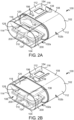
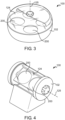
- FIGS. 1-5 show various examples of a demonstration device 100 having various shapes. For ease of description, the demonstration device 100 shown in FIGS. 1-2B will be described in detail.
- the optical article 200 has a forward or top surface 202, a rearward or bottom surface 204, and a side surface 206 extending between the top surface 202 and the bottom surface 204.
- the optical article 200 is an ophthalmic lens
- the bottom surface 204 is opposed to the eye of an individual wearing the optical article 200
- the side surface 206 typically resides within a supportive frame
- the top surface 202 faces incident light (not shown) at least a portion of which passes through the optical article 200 and into the individual's eye.
- the optical article 200 has at least one photochromic material configured to transition from an unactivated, or substantially colorless state, to an activated, or colored state in response to exposure to actinic radiation.
- the photochromic material may be applied to at least one surface of the optical article 200 in a coating or a film. Alternatively, or in addition, the photochromic material may be incorporated into the body of the optical article 200, such as by imbibition or prior to casting the optical article 200.
- t he demonstration device 100 includes a housing 102 having a sidewall 104 defining a hollow interior 106.
- the housing 102 at least partially encloses the components of the demonstration device 100. Some components of the demonstration device 100 may be completely enclosed within the housing 102, as discussed herein.
- the housing 102 may be of any suitable rigid material, such as plastic or metal.
- At least a portion of the sidewall 104 is transparent to allow viewing of the housing interior 106 from the outside of the housing 102 through the sidewall 104.
- the housing 102 includes a plurality of sides, including a top side 108 opposite a bottom side 110 with a pair of lateral sides 112, a front side 114 (shown in FIG. 2A ), and a rear side 116 (shown in FIG. 2A ) connected to each of the top side 108 and the bottom side 110.
- the housing 102 is monolithically formed as a single, integral part.
- the housing 102 is formed from a plurality of discrete parts that are removably or non-removably combined together.
- the housing 102 shown in FIGS. 1-2B has a substantially oval cross-section in a longitudinal cross plane, the housing 102 may have any other shape.
- the housing 102 may have a substantially circular cross-sectional shape.
- the housing 102 may have a substantially rectangular cross-sectional shape, such as shown in FIG. 5 .
- the housing 102 may have at least one opening 118 providing access to the interior 106.
- the opening 118 may be formed in one or more of the sides of the housing 102.
- the opening 118 may be enclosed by a cover panel or door 120.
- the door 120 may be movable between an open position, where the opening 118 is at least partially uncovered to provide access to the interior 106, and a closed position, where the opening 118 is closed to enclose the interior 106.
- the door 120 may be mounted on a hinge 122 to allow movement between the open position and the closed position.
- the door 120 may be configured for sliding movement relative to one or more sides of the housing 102.
- the housing 102 may have a first portion 102a and a second portion 102b.
- the first and second portions 102a, 102b may be removably or non-removably connected together.
- the interior 106 may be defined by one of the first portion 102a or the second portion 102b, while the other of the first portion 102 and the second portion 102b receives the components of the demonstration device 100 for demonstrating at least one thermally-reversible characteristic of an optical article 200 having at least one photochromic material, as discussed herein.
- At least one of the first portion 102a and the second portion 102b may be made from a transparent material.
- transparent means permitting visible light to pass through without diffusing or scattering the light.
- the door 120 may be provided on at least one of the first portion 102a and the second portion 102b.
- the inspection platform 124 may be movable relative to the housing 102, such as by being slidable and/or rotatable relative to the housing 102.
- the inspection platform 124 may be rotatable relative to the housing 102 about an axis 125
- the demonstration device 100 has at least one inspection light source 134 configured for illuminating at least a portion of the interior of the housing 102.
- the at least one inspection light source 134 may be positioned between the lower interior surface 130 of the housing 102 and the viewing stand 128 such that the light emitted from at least one inspection light source 130 passes through the transparent or translucent material of the viewing stand 128 to illuminate the optical article 200.
- the at least one inspection light source 134 may be placed on a side of the viewing stand 128 to illuminate the viewing stand 128 from at least one of its edges.
- the at least one inspection light source 134 may be configured for emitting one or more of wavelengths of visible light.
- the demonstration device 100 has at least one UV light source 136 configured to radiate ultraviolet light into the interior 106 of the housing 102.
- the at least one UV light source 136 may be configured for activating the photochromic compound(s) in the photochromic material of the optical article 200 due to exposure to actinic radiation emitted by the at least one UV light source 136.
- the at least one UV light source 136 may be configured for emitting electromagnetic radiation within the ultraviolet spectrum, such as electromagnetic radiation having wavelength in the range of 365-415 nm.
- the at least one UV light source 124 may have one or more UV emitters, such as one or more conventional UV lamps and/or one or more UV light-emitting diodes (LEDs).
- the at least one UV light source 124 may be a plurality of 1W 8Type UV LEDs.
- the at least one UV light source 136 may be fixedly or non-movably mounted on the housing 102. In other examples or aspects, at least one UV light source 136 may be movable relative to the housing 102. For example, as shown in FIG. 1 , the at least one UV light source 136 may be mounted to a movable frame 138 that is movable between a first position and a second position relative to the housing 102.
- the movable frame 138 may be positioned such that at least one UV light source 136 may be configured to irradiate at least a portion of the inspection platform 124, while, in the second position, the movable frame 138 is moved such that at least one UV light source 136 does not irradiate the inspection platform 124.
- the at least one UV light source 136 may be moved to the first position in order to activate the photochromic material of the optical article 200 supported on the inspection platform 124.
- the at least one UV light source 136 may be moved to the second position to allow for easier viewing of the optical article 200 as the photochromic material transitions from the activated state to an unactivated state.
- the movable frame 138 may be slidably movable relative to the housing 102 in a direction of arrow A in FIG. 1 .
- the movable frame 138 may be configured to slidably move the at least one UV light source 136 from the first portion 102a of the housing 102 toward the second portion 102b.
- the movable frame 138 may be rotatably movable relative to the housing 102.
- the movable frame 138 may have a gripping element 139 (shown in FIGS. 2A-2B ) for manually moving the frame 138 between the first and second positions.
- the movable frame 138 may have a motorized mechanism for moving the frame 138 between the first and second positions via a control element, such as a button, actuating one or more electric motors.
- the demonstration device 100 has at least one heating device 140 configured to heat at least a portion of the interior 106 of the housing 102.
- the at least one heating device 140 is configured to increase the temperature of the optical article 200 within the interior 106 of the housing 102 relative to ambient temperature surrounding the housing 102 in order to speed up the reverse transformation process of the photochromic compound(s) in the photochromic material from the activated (colored) state back to the unactivated (colorless) state.
- kinetics of the reverse transformation of the photochromic compound(s) from the activated to unactivated state increase with an increase in temperature.
- the at least one heating device 140 may be configured to maintain a predetermined temperature within the interior 106 of the housing 102.
- the at least one heating device 140 may be configured to maintain the interior 102 at a temperature in the range of 27 °C to 45 °C, for example in the range of 27 °C to 37 °C.
- the at least one heating device 140 may be at least one of a conductive heating device, a convective heating device, or a radiative heating device.
- the at least one heating device 140 has at least one heat source 142 and at least one fan 144.
- the at least one heat source 142 may be an electric heating element 146 thermally connected to a heat exchanger 148.
- the at least one fan 144 is configured to force air across the heat exchanger 148. Movement of air across the heat exchanger 148 heats the air.
- the at least one heat source 142 may be a cartridge heater configured for operating on a 12V DC power circuit.
- the cartridge heater may have a power of 40W.
- the at least one fan 144 may be a pair of fans, such as a pair of axial fans.
- the axial fans may have a diameter of 40 mm.
- the at least one heating device 140 may be an infrared heating device, such as an infrared heating lamp.
- temperature of the heated air in the interior 106 of the housing 102 may be controlled by controlling the number and speed of the fans 144 and the number and output of the heating elements 146.
- a temperature control element 150 such as a thermistor, may be provided for actuating at least one of the heating elements 146 and the fans 144. In some examples or aspects, the temperature control element 150 may be a 100 Kohm thermistor.
- the demonstration device 100 has at least one control device 152 operatively connected to at least one of the UV light source 136, the inspection light source 134, or the heating device 140.
- a single control device 152 may be configured to control each of the UV light source 136, the inspection light source 134, and the heating device 140.
- separate control devices 152 may be provided for each of the UV light source 136, the inspection light source 134, and the heating device 140.
- the at least one control device 152 may be configured to control at least one of an activation of the UV light source 136 or an intensity of the UV light source 136.
- the at least one control device 152 may be a microprocessor controller, such as an iOS Nano microprocessor controller.
- the at least one control device 152 may be configured for pulse width modulated (PWM) operation, wherein analog operation of at least one of the UV light source 136, the inspection light source 134, or the heating device 140 can be achieved using digital control signals.
- the at least one control device 152 may be configured for continuously modulated control of at least one of the UV light source 136, the inspection light source 134, or the heating device 140.
- the at least one control device 152 may have a proportional-integral-derivative PID controller.
- the user input device 154 includes an electronic visual display
- such visual display can be configured for receiving user input for controlling the operation of at least one of the UV light source 136, the inspection light source 134, or the heating device 140, and for communicating status information about an operating status or condition of the operation of at least one of the UV light source 136, the inspection light source 134, or the heating device 140.
- the user input device 154 may be an LCD touchscreen used to input commands to control operation of at least one of the UV light source 136, the inspection light source 134, or the heating device 140.
- One or more optical articles 200 are received within the interior 106 of the housing 102.
- the one or more optical articles 200 may be received within the interior 106 of the housing 102 by moving the door 120 from the closed position to an open position in order to provide an opening for inserting the one or more optical articles 200 into the interior 106 of the housing 102.
- Each optical article 200 may be supported by at least one surface thereof on the inspection platform.
- the bottom surface 204 of each optical article 200 may be supported on the support surface 132 of the viewing stand 128.
- the door 120 may be closed to enclose the housing 102.
- the at least one inspection light source 134 may be activated in order to illuminate the optical article 200 such that the reversible transformation of color due to activation/inactivation of the photochromic compound(s) in the photochromic material of the optical article 200 can be visually observed.
- Activation of the at least one inspection light source 134 may be controlled by the at least one control device 152, such as by receiving user input to activate the at least one inspection light source 134 on the user input device 154.
- Intensity of the at least one inspection light source 134 may be controlled by the at least one control device 152 in a similar manner.
- At least a portion of the optical article 200 having the photochromic material is irradiated with electromagnetic energy of appropriate wavelength to cause activation.
- Such irradiation of the optical article 200 is performed by activating the at least one UV light source 136.
- Activation of the at least one UV light source 136 may be controlled by the at least one control device 152, such as by receiving user input to activate the at least one UV light source 136 on the user input device 154.
- the user may activate the at least one UV light source 136 and set a duration of time during which the at least one UV light source 136 is to be active.
- activation time may be between 5 seconds to 30 seconds, depending on the intensity of the at least one UV light source 136 and/or the type of photochromic compound(s) in the photochromic material of the optical article 200.
- Intensity of the at least one UV light source 134 may be controlled by the at least one control device 152 in a similar manner.
- the at least one inspection light source 134 may be active or inactive while the at least one UV light source 136 is active.
- the at least one UV light source 136 may be moved to the first position such that the at least one UV light source 136 is positioned to irradiate at least a portion of the optical article 200 on the inspection platform 124. In this manner, the at least one UV light source 136 activates the photochromic material on the optical article 200 supported on the inspection platform 124. Upon activation of the photochromic compound, the at least one UV light source 136 may be moved to the second position to allow for easier viewing of the optical article 200.
- the temperature in the interior 106 of the housing 102 is controlled to be within the predetermined range.
- the increased temperature in the interior 106 of the housing 102 speeds up the reversible transition from the active (colored) state to inactive (colorless) state of the photochromic compound(s) in the photochromic material of the optical article 200.
- Such heating of the interior 106 of the housing 102, and thereby heating of the photochromic compound(s) in the photochromic material of the optical article 200 is performed by activating the at least one heating device 140.
- Activation of the at least one at least one heating device 140 may be controlled by the at least one control device 152, such as by receiving user input to activate the at least one at least one heating device 140 on the user input device 154.
- the user may activate the at least one at least one heating device 140 and set a duration of time during which the at least one at least one heating device 140 is to be active.
- Temperature of the at least one at least one heating device 140, or a desired temperature within the interior 106 of the housing 102 may be controlled by the at least one control device 152 in a similar manner.
- the at least one heating device 140 may be activated after deactivating the at least one UV light source 136.
- the at least one heating device 140 may be activated upon placement of the optical article 200 in the interior 106 of the housing 102.
- the increased temperature in the interior 106 of the housing 102 speeds up the reversible transformation of the photochromic compound(s) in the photochromic material of the optical article 200. from the active (colored) state to inactive (colorless) state.
Landscapes
- Physics & Mathematics (AREA)
- General Physics & Mathematics (AREA)
- Engineering & Computer Science (AREA)
- Pure & Applied Mathematics (AREA)
- Optics & Photonics (AREA)
- Mathematical Analysis (AREA)
- Mathematical Optimization (AREA)
- Mathematical Physics (AREA)
- Algebra (AREA)
- Business, Economics & Management (AREA)
- Computational Mathematics (AREA)
- Educational Administration (AREA)
- Educational Technology (AREA)
- Theoretical Computer Science (AREA)
- Chemical & Material Sciences (AREA)
- Analytical Chemistry (AREA)
- Investigating Materials By The Use Of Optical Means Adapted For Particular Applications (AREA)
- Testing Resistance To Weather, Investigating Materials By Mechanical Methods (AREA)
Claims (14)
- Demonstrationsvorrichtung (100) zum Demonstrieren mindestens einer thermisch umkehrbaren Eigenschaft eines optischen Erzeugnisses (200), das mindestens ein phototropes Material aufweist, wobei die Demonstrationsvorrichtung (100) Folgendes umfasst:ein Gehäuse (102) mit einer Seitenwand (104), die einen Innenraum (106) definiert;eine Prüfplattform (124) im Innenraum des Gehäuses (102), die zum Tragen zumindest eines Abschnitts des optischen Erzeugnisses (200) konfiguriert ist;mindestens eine Ultraviolett-Lichtquelle (136), die konfiguriert ist, ultraviolettes Licht in den Innenraum (106) des Gehäuses (102) abzustrahlen; undmindestens eine Prüflichtquelle (134), die konfiguriert ist, zumindest einen Abschnitt des Innenraums (106) des Gehäuses (102) zu beleuchten; dadurch gekennzeichnet, dasszumindest ein Abschnitt der Seitenwand (104) durchsichtig ist, um das Betrachten des Gehäuseinnenraums (106) von außerhalb des Gehäuses (102) durch die Seitenwand (104) zu ermöglichen;wobei die Demonstrationsvorrichtung ferner mindestens eine Heizvorrichtung (140) umfasst, die konfiguriert ist, zumindest einen Abschnitt des Innenraums (106) des Gehäuses (102) zu erwärmen, wobei die mindestens eine Heizvorrichtung (140) mindestens eine Wärmequelle (142) und mindestens einen Lüfter (144) umfasst.
- Demonstrationsvorrichtung (100) nach Anspruch 1, wobei die mindestens eine Wärmequelle (142) ein elektrisches Heizelement (146) ist, das mit einem Wärmetauscher (148) wärmetechnisch verbunden ist.
- Demonstrationsvorrichtung (100) nach einem der Ansprüche 1 oder 2, wobei die mindestens eine Heizvorrichtung (140) konfiguriert ist, eine Temperatur im Innenraum (106) des Gehäuses (102) bei einer Temperatur im Bereich von 27 °C bis 45 °C, vorzugsweise bei einer Temperatur im Bereich von 27 °C bis 37 °C aufrechtzuerhalten.
- Demonstrationsvorrichtung (100) nach einem der Ansprüche 1-3, die ferner mindestens eine Steuervorrichtung (152) umfasst, die mit der Ultraviolett-Lichtquelle (136) und/oder der Prüflichtquelle (134) und/oder der Heizvorrichtung (140) betriebstechnisch verbunden ist.
- Demonstrationsvorrichtung (100) nach Anspruch 4, wobei die Steuervorrichtung (152) eine Aktivierung der Ultraviolett-Lichtquelle (136) und/oder eine Intensität der Ultraviolett-Lichtquelle (136) und/oder eine Aktivierung der Prüflichtquelle (134) und/oder eine Intensität der Prüflichtquelle (134) und/oder eine Aktivierung der Heizvorrichtung (140) und/oder eine Temperatur der Heizvorrichtung (140) steuert.
- Demonstrationsvorrichtung (100) nach einem der Ansprüche 1-5, wobei das Gehäuse (102) einen ersten Abschnitt (102a), der den Innenraum (106) des Gehäuses (102) definiert, und einen zweiten Abschnitt (102b), der die Ultraviolett-Lichtquelle (136) und/oder die Prüflichtquelle (134) und/oder die Heizvorrichtung (140) aufnimmt, umfasst.
- Demonstrationsvorrichtung (100) nach Anspruch 6, wobei zumindest ein Abschnitt des ersten Abschnitts (102a) des Gehäuses (102) durchsichtig ist.
- Demonstrationsvorrichtung (100) nach Anspruch 6 oder 7, wobei die mindestens eine Ultraviolett-Lichtquelle (136) zwischen dem ersten Abschnitt (102a) und dem zweiten Abschnitt (102b) des Gehäuses (102) beweglich ist.
- Demonstrationsvorrichtung (100) nach einem der Ansprüche 1-8, wobei das Gehäuse (102) eine Tür (120) zum Verschließen des Innenraumes (106) des Gehäuses (102) umfasst.
- Demonstrationsvorrichtung (100) nach einem der Ansprüche 1-9, wobei die Prüfplattform (124) einen durchsichtigen oder lichtdurchlässigen Betrachtungssockel (128) umfasst.
- Demonstrationsvorrichtung (100) nach Anspruch 10, wobei die mindestens eine Prüflichtquelle (134) konfiguriert ist, eine Seitenfläche oder eine Bodenfläche des Betrachtungssockels (128) zu beleuchten.
- Verfahren zum Demonstrieren mindestens einer thermisch umkehrbaren Eigenschaft eines optischen Erzeugnisses (200), das mindestens ein phototropes Material aufweist, wobei das Verfahren Folgendes umfasst:Aufnehmen des optischen Erzeugnisses (200) in einem Innenraum (106) eines Gehäuses (102) einer Demonstrationsvorrichtung (100);Bestrahlen zumindest eines Abschnitts des optischen Erzeugnisses (200) mit ultraviolettem Licht von einer Ultraviolett-Lichtquelle (136), um eine phototrope Verbindung in dem phototropen Material auf dem optischen Erzeugnis (200) zu aktivieren; dadurch gekennzeichnet, dasszumindest ein Abschnitt einer Seitenwand (104) des Gehäuses (102) durchsichtig ist, um das Betrachten des Gehäuseinnenraums (106) von außerhalb des Gehäuses (102) durch die Seitenwand (104) zu ermöglichen;wobei das Verfahren ferner das Erwärmen zumindest eines Abschnitts des Innenraums (106) unter Verwendung mindestens einer Heizvorrichtung (140), die mindestens eine Wärmequelle (142) und mindestens einen Lüfter (144) umfasst, um die phototrope Verbindung zu deaktivieren, umfasst.
- Verfahren nach Anspruch 12, das ferner das Beleuchten zumindest eines Abschnitts des Innenraums (106) unter Verwendung einer Prüflichtquelle (134) umfasst.
- Verfahren nach Anspruch 12 oder 13, das ferner das Steuern einer Aktivierung der Ultraviolett-Lichtquelle (136) und/oder einer Intensität der Ultraviolett-Lichtquelle (136) und/oder einer Aktivierung der Prüflichtquelle (134) und/oder einer Intensität der Prüflichtquelle (134) und/oder einer Aktivierung der Heizvorrichtung (140) und/oder einer Temperatur der Heizvorrichtung (140) unter Verwendung mindestens einer Steuervorrichtung umfasst.
Applications Claiming Priority (1)
| Application Number | Priority Date | Filing Date | Title |
|---|---|---|---|
| PCT/EP2019/052336 WO2020156669A1 (en) | 2019-01-31 | 2019-01-31 | Demonstration device for photochromic lenses |
Publications (2)
| Publication Number | Publication Date |
|---|---|
| EP3918591A1 EP3918591A1 (de) | 2021-12-08 |
| EP3918591B1 true EP3918591B1 (de) | 2024-10-02 |
Family
ID=65276163
Family Applications (1)
| Application Number | Title | Priority Date | Filing Date |
|---|---|---|---|
| EP19702867.3A Active EP3918591B1 (de) | 2019-01-31 | 2019-01-31 | Demonstrationsvorrichtung für photochrome linsen |
Country Status (4)
| Country | Link |
|---|---|
| US (1) | US12217623B2 (de) |
| EP (1) | EP3918591B1 (de) |
| CN (1) | CN113366551B (de) |
| WO (1) | WO2020156669A1 (de) |
Families Citing this family (6)
| Publication number | Priority date | Publication date | Assignee | Title |
|---|---|---|---|---|
| CN113366551B (zh) * | 2019-01-31 | 2024-04-02 | 光学转变有限公司 | 用于光致变色镜片的演示装置 |
| US11741853B2 (en) * | 2019-05-14 | 2023-08-29 | Johnson & Johnson Vision Care, Inc. | Light-sensitive photochromic contact lens demonstration devices and related methods |
| EP4330949A1 (de) * | 2021-04-29 | 2024-03-06 | Transitions Optical, Ltd. | Demonstrationseinheit für photochrome linsen |
| CN113539030A (zh) * | 2021-07-22 | 2021-10-22 | 北京师范大学 | 一种多功能光学实验装置 |
| MX2024001335A (es) * | 2021-07-30 | 2024-02-14 | Transitions Optical Ltd | Dispositivo de caracterizacion para lente fotocromica con gradiente. |
| GB2625806A (en) * | 2022-12-23 | 2024-07-03 | Light Trace Photonics Ltd | Housing for accommodating a photonic integrated circuit chip |
Family Cites Families (19)
| Publication number | Priority date | Publication date | Assignee | Title |
|---|---|---|---|---|
| ATE18306T1 (de) * | 1982-05-13 | 1986-03-15 | Zeiss Carl Fa | Vorrichtung zur schnellen demonstration der wirkung phototroper objekte. |
| US6056421A (en) * | 1995-08-25 | 2000-05-02 | Michael Brian Johnson | Architectural lighting devices with photosensitive lens |
| US5989462A (en) * | 1997-07-31 | 1999-11-23 | Q2100, Inc. | Method and composition for producing ultraviolent blocking lenses |
| FR2907548B1 (fr) * | 2006-10-18 | 2009-01-16 | Essilor Int | Visualisation du pouvoir reflechissant de rayonnement ultraviolet d'un verre de lunettes |
| WO2010015990A2 (en) | 2008-08-07 | 2010-02-11 | Koninklijke Philips Electronics N.V. | Lighting device with dynamic light effects |
| US7688431B1 (en) * | 2009-04-09 | 2010-03-30 | Younger Mfg. Co. | Dispersion demonstrator for eyewear lenses |
| US8304747B2 (en) * | 2009-09-10 | 2012-11-06 | Xerox Corporation | Sensors and methods for determining whether an item has been exposed to an environmental condition |
| FR3006089B1 (fr) * | 2013-05-23 | 2015-05-22 | Essilor Int | Demonstrateur des qualites d'un materiau de verre de lunettes |
| US9798458B2 (en) * | 2013-10-02 | 2017-10-24 | The Joan and Irwin Jacobs Technion-Cornell Innovation Institute | Methods, systems, and apparatuses for accurate measurement and real-time feedback of solar ultraviolet exposure |
| JP2017524393A (ja) | 2014-05-28 | 2017-08-31 | パープルサン インコーポレイテッド | 紫外線照射のフォトクロミック検出 |
| US10718687B2 (en) * | 2015-06-25 | 2020-07-21 | Transitions Optical, Inc. | Inspection unit for photochromic ophthalmic lenses |
| JP6111313B1 (ja) * | 2015-11-04 | 2017-04-05 | 協和界面科学株式会社 | 防曇性評価装置および防曇性評価方法 |
| US10369243B2 (en) * | 2015-12-07 | 2019-08-06 | Diversey, Inc. | Photochromic indicator and a method of documenting decontamination of an object using a photochromic indicator |
| CN109476100A (zh) | 2016-07-15 | 2019-03-15 | 光学转变有限公司 | 用于用光致变色涂料精确涂布眼科透镜的方法和装置 |
| BR112019012186B1 (pt) * | 2016-12-30 | 2022-11-22 | Transitions Optical, Ltd | Método para a determinação das características ao ar livre de um artigo ótico fotocrômico, método e sistema para a seleção de um artigo ótico fotocrômico |
| CN111670350B (zh) * | 2017-12-28 | 2022-06-10 | 光学转变有限公司 | 用于测量隐形眼镜的光学特性的方法和系统 |
| US11422089B2 (en) * | 2017-12-28 | 2022-08-23 | Transitions Optical, Ltd. | Method for measuring optical characteristics of a transparent article |
| CN113366551B (zh) * | 2019-01-31 | 2024-04-02 | 光学转变有限公司 | 用于光致变色镜片的演示装置 |
| EP4330949A1 (de) * | 2021-04-29 | 2024-03-06 | Transitions Optical, Ltd. | Demonstrationseinheit für photochrome linsen |
-
2019
- 2019-01-31 CN CN201980090852.5A patent/CN113366551B/zh active Active
- 2019-01-31 US US17/427,245 patent/US12217623B2/en active Active
- 2019-01-31 WO PCT/EP2019/052336 patent/WO2020156669A1/en not_active Ceased
- 2019-01-31 EP EP19702867.3A patent/EP3918591B1/de active Active
Also Published As
| Publication number | Publication date |
|---|---|
| US12217623B2 (en) | 2025-02-04 |
| CN113366551A (zh) | 2021-09-07 |
| EP3918591A1 (de) | 2021-12-08 |
| US20220122485A1 (en) | 2022-04-21 |
| CN113366551B (zh) | 2024-04-02 |
| WO2020156669A1 (en) | 2020-08-06 |
Similar Documents
| Publication | Publication Date | Title |
|---|---|---|
| EP3918591B1 (de) | Demonstrationsvorrichtung für photochrome linsen | |
| US10444800B2 (en) | System for protecting headset components from sunlight | |
| KR102927325B1 (ko) | 협대역 시스템에서 조작된 조사 패턴을 생성하기 위한 방법 및 시스템 | |
| CN106794054B (zh) | 技工用聚合装置 | |
| EP3314240B1 (de) | Inspektionseinheit für photochrome brillengläser | |
| US20230005389A1 (en) | Light-sensitive photochromic contact lens demonstration devices and related methods | |
| EP1525868B1 (de) | Integriertes Untersuchungslicht für einen Inkubator | |
| KR20250137163A (ko) | 필터 및 광 기기 | |
| WO2020046298A1 (en) | Myopia inhibition apparatus and ocular method | |
| WO2018055418A1 (en) | Illuminated eyewear device | |
| US20240210273A1 (en) | Photochromic Lens Demonstration Unit | |
| KR20240035935A (ko) | 면도 유닛 및 이를 포함하는 전기 면도기 | |
| KR102306417B1 (ko) | 시각적 스트레스 검사 장치 | |
| US10401004B2 (en) | Head-mounted type lighting device | |
| CN111650162B (zh) | 光致变色玻璃的光色性能检测方法及检测装置 | |
| KR20240040865A (ko) | 제스처 인식 사용자 인터페이스 스마트 조명장치 | |
| JP6608362B2 (ja) | 光治療プラットフォームシステム | |
| CN221858410U (zh) | 一种近视防控仪的光源调节机构 | |
| KR20240152556A (ko) | 다기능 광원을 구비한 탈착식 휴대용 램프 | |
| JP2022153204A (ja) | 紫外線殺菌装置 | |
| KR20240129492A (ko) | 컨트롤 패널 및 이를 포함하는 가전 기기, 가전 기기 제어 방법 | |
| CN118665516A (zh) | 一种用于驾驶室光环境人因工程效应的调光控制装置 | |
| KR20220154961A (ko) | 체온 측정가능한 거울 |
Legal Events
| Date | Code | Title | Description |
|---|---|---|---|
| STAA | Information on the status of an ep patent application or granted ep patent |
Free format text: STATUS: UNKNOWN |
|
| STAA | Information on the status of an ep patent application or granted ep patent |
Free format text: STATUS: THE INTERNATIONAL PUBLICATION HAS BEEN MADE |
|
| PUAI | Public reference made under article 153(3) epc to a published international application that has entered the european phase |
Free format text: ORIGINAL CODE: 0009012 |
|
| STAA | Information on the status of an ep patent application or granted ep patent |
Free format text: STATUS: REQUEST FOR EXAMINATION WAS MADE |
|
| 17P | Request for examination filed |
Effective date: 20210816 |
|
| AK | Designated contracting states |
Kind code of ref document: A1 Designated state(s): AL AT BE BG CH CY CZ DE DK EE ES FI FR GB GR HR HU IE IS IT LI LT LU LV MC MK MT NL NO PL PT RO RS SE SI SK SM TR |
|
| DAV | Request for validation of the european patent (deleted) | ||
| DAX | Request for extension of the european patent (deleted) | ||
| STAA | Information on the status of an ep patent application or granted ep patent |
Free format text: STATUS: EXAMINATION IS IN PROGRESS |
|
| 17Q | First examination report despatched |
Effective date: 20230113 |
|
| P01 | Opt-out of the competence of the unified patent court (upc) registered |
Effective date: 20230516 |
|
| GRAP | Despatch of communication of intention to grant a patent |
Free format text: ORIGINAL CODE: EPIDOSNIGR1 |
|
| STAA | Information on the status of an ep patent application or granted ep patent |
Free format text: STATUS: GRANT OF PATENT IS INTENDED |
|
| INTG | Intention to grant announced |
Effective date: 20240528 |
|
| GRAS | Grant fee paid |
Free format text: ORIGINAL CODE: EPIDOSNIGR3 |
|
| GRAA | (expected) grant |
Free format text: ORIGINAL CODE: 0009210 |
|
| STAA | Information on the status of an ep patent application or granted ep patent |
Free format text: STATUS: THE PATENT HAS BEEN GRANTED |
|
| AK | Designated contracting states |
Kind code of ref document: B1 Designated state(s): AL AT BE BG CH CY CZ DE DK EE ES FI FR GB GR HR HU IE IS IT LI LT LU LV MC MK MT NL NO PL PT RO RS SE SI SK SM TR |
|
| REG | Reference to a national code |
Ref country code: GB Ref legal event code: FG4D |
|
| REG | Reference to a national code |
Ref country code: CH Ref legal event code: EP |
|
| REG | Reference to a national code |
Ref country code: IE Ref legal event code: FG4D |
|
| REG | Reference to a national code |
Ref country code: DE Ref legal event code: R096 Ref document number: 602019059684 Country of ref document: DE |
|
| REG | Reference to a national code |
Ref country code: LT Ref legal event code: MG9D |
|
| REG | Reference to a national code |
Ref country code: NL Ref legal event code: MP Effective date: 20241002 |
|
| REG | Reference to a national code |
Ref country code: AT Ref legal event code: MK05 Ref document number: 1729055 Country of ref document: AT Kind code of ref document: T Effective date: 20241002 |
|
| PG25 | Lapsed in a contracting state [announced via postgrant information from national office to epo] |
Ref country code: NL Free format text: LAPSE BECAUSE OF FAILURE TO SUBMIT A TRANSLATION OF THE DESCRIPTION OR TO PAY THE FEE WITHIN THE PRESCRIBED TIME-LIMIT Effective date: 20241002 |
|
| PG25 | Lapsed in a contracting state [announced via postgrant information from national office to epo] |
Ref country code: NL Free format text: LAPSE BECAUSE OF FAILURE TO SUBMIT A TRANSLATION OF THE DESCRIPTION OR TO PAY THE FEE WITHIN THE PRESCRIBED TIME-LIMIT Effective date: 20241002 |
|
| PG25 | Lapsed in a contracting state [announced via postgrant information from national office to epo] |
Ref country code: PT Free format text: LAPSE BECAUSE OF FAILURE TO SUBMIT A TRANSLATION OF THE DESCRIPTION OR TO PAY THE FEE WITHIN THE PRESCRIBED TIME-LIMIT Effective date: 20250203 Ref country code: HR Free format text: LAPSE BECAUSE OF FAILURE TO SUBMIT A TRANSLATION OF THE DESCRIPTION OR TO PAY THE FEE WITHIN THE PRESCRIBED TIME-LIMIT Effective date: 20241002 Ref country code: IS Free format text: LAPSE BECAUSE OF FAILURE TO SUBMIT A TRANSLATION OF THE DESCRIPTION OR TO PAY THE FEE WITHIN THE PRESCRIBED TIME-LIMIT Effective date: 20250202 |
|
| PGFP | Annual fee paid to national office [announced via postgrant information from national office to epo] |
Ref country code: DE Payment date: 20250129 Year of fee payment: 7 |
|
| PG25 | Lapsed in a contracting state [announced via postgrant information from national office to epo] |
Ref country code: FI Free format text: LAPSE BECAUSE OF FAILURE TO SUBMIT A TRANSLATION OF THE DESCRIPTION OR TO PAY THE FEE WITHIN THE PRESCRIBED TIME-LIMIT Effective date: 20241002 |
|
| PG25 | Lapsed in a contracting state [announced via postgrant information from national office to epo] |
Ref country code: BG Free format text: LAPSE BECAUSE OF FAILURE TO SUBMIT A TRANSLATION OF THE DESCRIPTION OR TO PAY THE FEE WITHIN THE PRESCRIBED TIME-LIMIT Effective date: 20241002 |
|
| PG25 | Lapsed in a contracting state [announced via postgrant information from national office to epo] |
Ref country code: ES Free format text: LAPSE BECAUSE OF FAILURE TO SUBMIT A TRANSLATION OF THE DESCRIPTION OR TO PAY THE FEE WITHIN THE PRESCRIBED TIME-LIMIT Effective date: 20241002 |
|
| PG25 | Lapsed in a contracting state [announced via postgrant information from national office to epo] |
Ref country code: NO Free format text: LAPSE BECAUSE OF FAILURE TO SUBMIT A TRANSLATION OF THE DESCRIPTION OR TO PAY THE FEE WITHIN THE PRESCRIBED TIME-LIMIT Effective date: 20250102 |
|
| PG25 | Lapsed in a contracting state [announced via postgrant information from national office to epo] |
Ref country code: AT Free format text: LAPSE BECAUSE OF FAILURE TO SUBMIT A TRANSLATION OF THE DESCRIPTION OR TO PAY THE FEE WITHIN THE PRESCRIBED TIME-LIMIT Effective date: 20241002 Ref country code: LV Free format text: LAPSE BECAUSE OF FAILURE TO SUBMIT A TRANSLATION OF THE DESCRIPTION OR TO PAY THE FEE WITHIN THE PRESCRIBED TIME-LIMIT Effective date: 20241002 Ref country code: GR Free format text: LAPSE BECAUSE OF FAILURE TO SUBMIT A TRANSLATION OF THE DESCRIPTION OR TO PAY THE FEE WITHIN THE PRESCRIBED TIME-LIMIT Effective date: 20250103 |
|
| PG25 | Lapsed in a contracting state [announced via postgrant information from national office to epo] |
Ref country code: PL Free format text: LAPSE BECAUSE OF FAILURE TO SUBMIT A TRANSLATION OF THE DESCRIPTION OR TO PAY THE FEE WITHIN THE PRESCRIBED TIME-LIMIT Effective date: 20241002 Ref country code: CZ Free format text: LAPSE BECAUSE OF FAILURE TO SUBMIT A TRANSLATION OF THE DESCRIPTION OR TO PAY THE FEE WITHIN THE PRESCRIBED TIME-LIMIT Effective date: 20241002 |
|
| PGFP | Annual fee paid to national office [announced via postgrant information from national office to epo] |
Ref country code: FR Payment date: 20250127 Year of fee payment: 7 |
|
| PGFP | Annual fee paid to national office [announced via postgrant information from national office to epo] |
Ref country code: IT Payment date: 20250121 Year of fee payment: 7 |
|
| PG25 | Lapsed in a contracting state [announced via postgrant information from national office to epo] |
Ref country code: RS Free format text: LAPSE BECAUSE OF FAILURE TO SUBMIT A TRANSLATION OF THE DESCRIPTION OR TO PAY THE FEE WITHIN THE PRESCRIBED TIME-LIMIT Effective date: 20250102 |
|
| PG25 | Lapsed in a contracting state [announced via postgrant information from national office to epo] |
Ref country code: SM Free format text: LAPSE BECAUSE OF FAILURE TO SUBMIT A TRANSLATION OF THE DESCRIPTION OR TO PAY THE FEE WITHIN THE PRESCRIBED TIME-LIMIT Effective date: 20241002 |
|
| REG | Reference to a national code |
Ref country code: DE Ref legal event code: R097 Ref document number: 602019059684 Country of ref document: DE |
|
| PG25 | Lapsed in a contracting state [announced via postgrant information from national office to epo] |
Ref country code: DK Free format text: LAPSE BECAUSE OF FAILURE TO SUBMIT A TRANSLATION OF THE DESCRIPTION OR TO PAY THE FEE WITHIN THE PRESCRIBED TIME-LIMIT Effective date: 20241002 |
|
| PG25 | Lapsed in a contracting state [announced via postgrant information from national office to epo] |
Ref country code: EE Free format text: LAPSE BECAUSE OF FAILURE TO SUBMIT A TRANSLATION OF THE DESCRIPTION OR TO PAY THE FEE WITHIN THE PRESCRIBED TIME-LIMIT Effective date: 20241002 |
|
| PG25 | Lapsed in a contracting state [announced via postgrant information from national office to epo] |
Ref country code: RO Free format text: LAPSE BECAUSE OF FAILURE TO SUBMIT A TRANSLATION OF THE DESCRIPTION OR TO PAY THE FEE WITHIN THE PRESCRIBED TIME-LIMIT Effective date: 20241002 |
|
| PG25 | Lapsed in a contracting state [announced via postgrant information from national office to epo] |
Ref country code: SK Free format text: LAPSE BECAUSE OF FAILURE TO SUBMIT A TRANSLATION OF THE DESCRIPTION OR TO PAY THE FEE WITHIN THE PRESCRIBED TIME-LIMIT Effective date: 20241002 |
|
| PLBE | No opposition filed within time limit |
Free format text: ORIGINAL CODE: 0009261 |
|
| STAA | Information on the status of an ep patent application or granted ep patent |
Free format text: STATUS: NO OPPOSITION FILED WITHIN TIME LIMIT |
|
| REG | Reference to a national code |
Ref country code: CH Ref legal event code: PL |
|
| PG25 | Lapsed in a contracting state [announced via postgrant information from national office to epo] |
Ref country code: SE Free format text: LAPSE BECAUSE OF FAILURE TO SUBMIT A TRANSLATION OF THE DESCRIPTION OR TO PAY THE FEE WITHIN THE PRESCRIBED TIME-LIMIT Effective date: 20241002 |
|
| 26N | No opposition filed |
Effective date: 20250703 |
|
| PG25 | Lapsed in a contracting state [announced via postgrant information from national office to epo] |
Ref country code: LU Free format text: LAPSE BECAUSE OF NON-PAYMENT OF DUE FEES Effective date: 20250131 Ref country code: MC Free format text: LAPSE BECAUSE OF FAILURE TO SUBMIT A TRANSLATION OF THE DESCRIPTION OR TO PAY THE FEE WITHIN THE PRESCRIBED TIME-LIMIT Effective date: 20241002 |
|
| GBPC | Gb: european patent ceased through non-payment of renewal fee |
Effective date: 20250131 |
|
| PG25 | Lapsed in a contracting state [announced via postgrant information from national office to epo] |
Ref country code: GB Free format text: LAPSE BECAUSE OF NON-PAYMENT OF DUE FEES Effective date: 20250131 Ref country code: BE Free format text: LAPSE BECAUSE OF NON-PAYMENT OF DUE FEES Effective date: 20250131 |
|
| PG25 | Lapsed in a contracting state [announced via postgrant information from national office to epo] |
Ref country code: CH Free format text: LAPSE BECAUSE OF NON-PAYMENT OF DUE FEES Effective date: 20250131 |
|
| REG | Reference to a national code |
Ref country code: BE Ref legal event code: MM Effective date: 20250131 |
|
| PG25 | Lapsed in a contracting state [announced via postgrant information from national office to epo] |
Ref country code: IE Free format text: LAPSE BECAUSE OF NON-PAYMENT OF DUE FEES Effective date: 20250131 |