EP3918355B1 - Knotenfehlerdetektion und -auflösung in verteilten datenbanken - Google Patents
Knotenfehlerdetektion und -auflösung in verteilten datenbanken Download PDFInfo
- Publication number
- EP3918355B1 EP3918355B1 EP20749510.2A EP20749510A EP3918355B1 EP 3918355 B1 EP3918355 B1 EP 3918355B1 EP 20749510 A EP20749510 A EP 20749510A EP 3918355 B1 EP3918355 B1 EP 3918355B1
- Authority
- EP
- European Patent Office
- Prior art keywords
- nodes
- node
- fully connected
- connected component
- failure
- Prior art date
- Legal status (The legal status is an assumption and is not a legal conclusion. Google has not performed a legal analysis and makes no representation as to the accuracy of the status listed.)
- Active
Links
Images


Classifications
-
- G—PHYSICS
- G01—MEASURING; TESTING
- G01R—MEASURING ELECTRIC VARIABLES; MEASURING MAGNETIC VARIABLES
- G01R31/00—Arrangements for testing electric properties; Arrangements for locating electric faults; Arrangements for electrical testing characterised by what is being tested not provided for elsewhere
- G01R31/08—Locating faults in cables, transmission lines, or networks
-
- H—ELECTRICITY
- H04—ELECTRIC COMMUNICATION TECHNIQUE
- H04L—TRANSMISSION OF DIGITAL INFORMATION, e.g. TELEGRAPHIC COMMUNICATION
- H04L69/00—Network arrangements, protocols or services independent of the application payload and not provided for in the other groups of this subclass
- H04L69/40—Network arrangements, protocols or services independent of the application payload and not provided for in the other groups of this subclass for recovering from a failure of a protocol instance or entity, e.g. service redundancy protocols, protocol state redundancy or protocol service redirection
-
- G—PHYSICS
- G06—COMPUTING OR CALCULATING; COUNTING
- G06F—ELECTRIC DIGITAL DATA PROCESSING
- G06F11/00—Error detection; Error correction; Monitoring
- G06F11/07—Responding to the occurrence of a fault, e.g. fault tolerance
- G06F11/16—Error detection or correction of the data by redundancy in hardware
- G06F11/18—Error detection or correction of the data by redundancy in hardware using passive fault-masking of the redundant circuits
- G06F11/181—Eliminating the failing redundant component
-
- G—PHYSICS
- G06—COMPUTING OR CALCULATING; COUNTING
- G06F—ELECTRIC DIGITAL DATA PROCESSING
- G06F16/00—Information retrieval; Database structures therefor; File system structures therefor
- G06F16/20—Information retrieval; Database structures therefor; File system structures therefor of structured data, e.g. relational data
- G06F16/27—Replication, distribution or synchronisation of data between databases or within a distributed database system; Distributed database system architectures therefor
-
- H—ELECTRICITY
- H04—ELECTRIC COMMUNICATION TECHNIQUE
- H04L—TRANSMISSION OF DIGITAL INFORMATION, e.g. TELEGRAPHIC COMMUNICATION
- H04L12/00—Data switching networks
- H04L12/02—Details
- H04L12/16—Arrangements for providing special services to substations
- H04L12/18—Arrangements for providing special services to substations for broadcast or conference, e.g. multicast
- H04L12/1863—Arrangements for providing special services to substations for broadcast or conference, e.g. multicast comprising mechanisms for improved reliability, e.g. status reports
- H04L12/1877—Measures taken prior to transmission
-
- H—ELECTRICITY
- H04—ELECTRIC COMMUNICATION TECHNIQUE
- H04L—TRANSMISSION OF DIGITAL INFORMATION, e.g. TELEGRAPHIC COMMUNICATION
- H04L41/00—Arrangements for maintenance, administration or management of data switching networks, e.g. of packet switching networks
- H04L41/06—Management of faults, events, alarms or notifications
- H04L41/0631—Management of faults, events, alarms or notifications using root cause analysis; using analysis of correlation between notifications, alarms or events based on decision criteria, e.g. hierarchy, tree or time analysis
-
- H—ELECTRICITY
- H04—ELECTRIC COMMUNICATION TECHNIQUE
- H04L—TRANSMISSION OF DIGITAL INFORMATION, e.g. TELEGRAPHIC COMMUNICATION
- H04L41/00—Arrangements for maintenance, administration or management of data switching networks, e.g. of packet switching networks
- H04L41/06—Management of faults, events, alarms or notifications
- H04L41/0686—Additional information in the notification, e.g. enhancement of specific meta-data
-
- H—ELECTRICITY
- H04—ELECTRIC COMMUNICATION TECHNIQUE
- H04L—TRANSMISSION OF DIGITAL INFORMATION, e.g. TELEGRAPHIC COMMUNICATION
- H04L43/00—Arrangements for monitoring or testing data switching networks
- H04L43/08—Monitoring or testing based on specific metrics, e.g. QoS, energy consumption or environmental parameters
- H04L43/0805—Monitoring or testing based on specific metrics, e.g. QoS, energy consumption or environmental parameters by checking availability
- H04L43/0811—Monitoring or testing based on specific metrics, e.g. QoS, energy consumption or environmental parameters by checking availability by checking connectivity
-
- G—PHYSICS
- G06—COMPUTING OR CALCULATING; COUNTING
- G06F—ELECTRIC DIGITAL DATA PROCESSING
- G06F2201/00—Indexing scheme relating to error detection, to error correction, and to monitoring
- G06F2201/80—Database-specific techniques
Definitions
- a system for detecting malicious gray-hole nodes in a mobile ad hoc network comprising a group of nodes is disclosed.
- the processor at a first node in the plurality of nodes can be configured to resolve a failure in the distributed database system by: identifying a suspicious node in the plurality of nodes, broadcasting a first list of suspicious nodes to neighbor nodes in the plurality of nodes, receiving a second list of suspicious nodes from at least one other neighbor node, determining whether the first node is in a winning fully connected component of the distributed database based on the connectivity information, in response to determining that the first node is in the winning fully connected component of the plurality of nodes, continuing to operate the first node, and in response to determining that the first node is not in the winning fully connected component of the plurality of nodes, failing the first node to resolve the failure.
- the suspicious node can be a node in the plurality of nodes that is no longer connected to the first node as a result of the failure in the distributed database system.
- the first list of suspicious nodes can include the suspicious node.
- the neighbor node can be nodes in the plurality of nodes that remain directly connected to the first node after the network failure.
- the winning fully connected component can include more than half of the nodes in the plurality of nodes and each node in the winning fully connected component is directly connected to each other node in the winning fully connected component.
- a distributed database system includes multiple nodes that store fragments of data and/or metadata of a distributed database. All of the nodes in the distributed database system are connected directly to each other in a manner such that they can communicate with each other. However, there can be instances when one or more nodes in the distributed database system experience interruptions in communication due to network failure. These interruptions in communication can be due to a failed communication link between two or more nodes or due to a failure of one or more nodes. These failures can be resolved by identifying which nodes are still connected directly to each other, identifying the largest group of directly connected nodes, and failing the nodes that aren't part of that group as explained in greater detail below.
- a distributed database system can include two types of nodes - transaction engine (TE) nodes that provide a user access to the distributed database, and storage manager (SM) nodes that maintain respective disk archives of the entire distributed database. While each storage manager node normally stores a copy of the entire distributed database, a single transaction engine node may contain only the portion of the distributed database necessary to support transactions being performed at that transaction engine node at that time.
- TE transaction engine
- SM storage manager
- Each node in the distributed database system has its own processor, memory, and communications interface(s) and can communicate directly with every other node in the distributed database system through a database system network. Communications between any two nodes can include transmitting serialized messages.
- the serialized messages can follow the Transmission Control Protocol (TCP) or any other suitable messaging protocol.
- TCP Transmission Control Protocol
- Each node in the distributed database system has a unique identifier (e.g., a lexicographic id) and stores a list of every other node, by unique identifier, in the distributed database system. Each node uses this list to track the status of every transaction engine node and storage manager node in the distributed database system. In addition, each node may track every database transaction and the locations of every database record (i.e., which nodes store which data fragments). The nodes may store this node and transaction information in respective copies of a master catalog that contains metadata about the distributed database system and is replicated across all nodes in the database. A new node receives a copy of the master catalog from another node, called an entry node, when it joins the distributed database system.
- a unique identifier e.g., a lexicographic id
- Tracking database transactions and the locations database fragments helps the distributed database system maintain Atomicity, Consistency, Isolation, and Durability - commonly known as ACID properties - in order to ensure accuracy, completeness, and integrity of the data in the distributed database.
- Each node in the distributed database system transmits "heartbeat" messages to every other node in the distributed database system at frequent intervals. For instance, each node sends heartbeat messages to every other node every second or couple of seconds . (Optionally, a node that receives a heartbeat message can transmit an acknowledgement message to the node that transmitted the heartbeat message.) If there is no interruption in communication, every node in the distributed database system continues to send heartbeat messages directly to and receive heartbeat messages directly from every other node in the distributed database system. However, a network failure can interrupt such communication. A node that detects an interruption in communication (e.g., not receiving a heartbeat message within a predetermined amount of time from another node) initiates a failure resolution protocol to resolve the network failure.
- a failure resolution protocol to resolve the network failure.
- the nodes in a distributed database regroup themselves in response to a network failure and fail themselves if they are not part of the largest fully connected group of nodes of majority size with the lowest lexicographical id ordering. If the largest fully connected group includes fewer than half the nodes in the distributed database system, then all of the nodes may fail themselves. Failing disconnected or partially connected nodes reduces the possibility that some or all of the database may become invalid.
- the failure resolution processes can be carried out in a leaderless fashion without blocking or aborting ongoing database transactions.
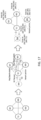
- FIG. 1 illustrates a process 100 of resolving network failures. Any node in a distributed database system can initiate this process 100 in response to detecting a network failure (e.g., failure to receive a heartbeat message from another node within a predetermined period).
- a network failure e.g., failure to receive a heartbeat message from another node within a predetermined period.
- a first node detects a network failure and initiates the failure resolution process 100 by creating a list of "suspect nodes," i.e., nodes that the first node suspects to have failed.
- the suspect list of the first node is a list of nodes that meet one or both of the following conditions: (a) the first node hasn't received a heartbeat message from those nodes within a predetermined timeout interval (e.g., pingTimeout seconds); and (b) the operating system has closed the connection(s) between the first node and the other node(s).
- a predetermined timeout interval e.g., pingTimeout seconds
- the first node's suspect list includes every other node in the distributed database system, the first node may fail itself to at least partially resolve the network failure.
- the first node i.e., the node that initiated process 100
- the neighbor nodes receive this suspect list and broadcast their own suspect lists to their neighbors.
- the neighbor nodes' suspect lists may be identical to or different from the first node's suspect list depending on the nature of the network failure.
- the first node receives the suspect lists from its neighbor nodes and uses them and its own suspect list to construct a connectivity graph.
- the connectivity graph shows which nodes in the distributed database system the first node is actually directly connected to (i.e., which nodes are actually the first node's neighbor nodes).
- the other nodes also construct connectivity graphs. Depending on the nature of the network failure, these connectivity graphs may be the same as or different than the first node's connectivity graph. Similarly, each connectivity graph may be the complement of the corresponding node's suspect list.
- Each node uses its connectivity graph to identify groups of nodes that remain directly connected to each other after the network failure. Each group of directly connected nodes is called a "fully connected component.” In a fully connected component, each node continues to communicate with every other node within the fully connected component after the network failure. Once each node has identified the fully connected components within the distributed database system, it determines whether it is part of the "winning fully connected component" (110). If it is not part of a fully connected component, each node fails itself to resolve the network failure (112). If it is part of the winning fully connected component, it continues to operate (114).
- a winning fully connected component can but does not have to include all the data in the database (e.g., it does not have to include a storage manager node).
- the procedure doesn't account for the types of nodes that form a winning fully connected component. (In some cases, though, the process can be modified to pay attention to the type of nodes in the fully connected components when determining the winning fully connected component.) If the winning fully connected component doesn't include all the data in the distributed database, then the user may intervene to ensure proper operation.
- Each node can determine whether it is part of the winning fully connected component as follows. First, each node may determine if it is part of a fully connected component based on its connectivity graph. If not, it fails itself. But if a node is part of a fully connected component (or possibly more than one fully connected component), it determines the sizes of its fully connected component(s) based on its connectivity graph. If a node determines that it's not part of the largest fully connected component (based on its connectivity graph and information that each node stores about the other nodes in the distributed database system), it fails itself (112). If a node is part of the largest fully connected component, and that fully connected component contains more than half the total number of nodes in the distributed database system prior to the network failure, the node remains operational (114). This fully connected component is called the "winning fully connected component" because, at the end of the failure resolution process 100, it contains all of the operational nodes in the distributed database system.
- a node determines that there are two or more fully connected components that are the same size, each with more than half the nodes in the distributed database, and that are larger than all of the other fully connected components, it implements a tie-breaking process to identify the winning fully connected component.
- the tie-breaking process may include sorting the nodes in each fully connected component by the nodes' unique identifiers. Once the unique identifiers are sorted, the node picks the winning fully connected component based on a lexicographic ordering of the unique identifiers. For example, the node may pick the fully connected component with the lowest node id following a common prefix as the winning fully connected component.
- the failure resolution process illustrated in FIG. 1 has several differences and advantages over other processes for resolving failures in distributed databases. To start, unlike blocking processes, the failure resolution process illustrated in FIG. 1 evicts one or more nodes in the distributed database after a network failure to restore full, complete connectivity. Blocking is undesirable because it could roll back updates that are made to the data in the distributed database. Unlike other methodologies, the processes described herein does not include any sort of blocking mechanism.
- the failure resolution process illustrated in FIG. 1 does not require or use a leader node.
- other methodologies for resolving failures in a distributed database implement a strong leadership model. Basically, this methodology uses a leader node to make a failure resolution decision. Unlike this leader-based methodology, the processes described herein does not have a leader node that makes failure resolution decisions. Instead, as described above with respect to FIG. 1 , any node can start the failure resolution process, and each node determines whether to fail itself or remain operational as part of the process without instructions from a leader node.
- the non-blocking, leader-less failure resolution processes disclosed here can handle partial-connectivity network failures in a consistent manner.
- a network partition within a distributed database system can cause a node or a set of nodes to communicate with only a subset of nodes in the distributed database system.
- other processes apply a rotating leader model to make the leader and informers use explicit message acknowledgements.
- the process 100 does not let two or more disjoint groups of nodes (i.e., different fully connected components) stay up after a network failure event. To avoid trivial solutions (e.g., failing all of the nodes), the process 100 allows, where possible, a single group of nodes to stay up.
- process 100 may not necessarily cause the rest of the nodes to fail.
- Process 100 can also handle slow links (i.e., communication path between two or more nodes where the connectivity is slow) in addition to link failures. Put differently, process 100 treats slow links and link failures in the same manner.
- FIGS. 2-10 illustrate different types of network failures that can be resolved using the process 100 in FIG. 1 .
- FIG. 2 shows the classic failure case, where a network partition event splits a distributed database system 200 into two or more disjoint groups of fully connected nodes.
- the distributed database system 200 includes three transaction engine nodes TE1, TE2, and TE3 and two storage manager nodes SM1 and SM2, all of which are connected to each other.
- TE1 communicates with TE2 via link 212a
- TE2 communicates with TE3 via link 212d
- TE3 communicates with SM2 via link 212e
- SM2 communicates with SM1 via link 212f
- TE2 communicates with SM1 via link 212b
- TE2 communicates with SM1 via link 212c
- TE1 communicates with SM2 via link 212h
- TE3 communicates with SM1 via link 212j
- TE2 communicates with SM2 via link 212i.
- a network partition splits the chorus into two disjoint groups of nodes (two fully connected components 202' and 202'').
- the chorus or chorus group is the set of all nodes in the distributed database system.
- the first fully connected component 202' includes ⁇ TE1, TE2, SM1 ⁇
- the second fully connected component 202'' includes ⁇ TE3, SM2 ⁇ .
- the process 100 decides the first fully connected component 202' is the winning fully connected component 204' because it is larger than the second fully connected component 202" and includes more than half the nodes in the distributed database 200.
- the nodes ⁇ TE1, TE2, SM1 ⁇ in the winning fully connected component 204' stay up, and nodes TE3 and SM2 fail themselves in response to discovering that they aren't in the winning fully connected component 204'.
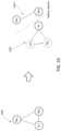
- FIG. 3 illustrates a distributed database system 300 with three nodes TE1, TE2, and SM1.
- three nodes TE1, TE2, and SM1 form a chorus group with TE1 communicating with TE2 via link 212a, TE2 communicating with SM1 via link 212b, and SM1 communicating with TE1 via link 212c.
- a failure of link 212a between TE1 and TE2 (or a network partition between the data centers of TE1 and TE2, assuming TE1 and TE2 are in different data centers) creates two fully connected components 202' ⁇ SM1, TE1 ⁇ and 202" ⁇ SM1, TE2 ⁇ , with partial connectivity for nodes TE1 and TE2.
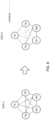
- FIG. 4 illustrates a distributed database system 400 with a chorus group of five nodes TE1, TE2, TE3, SM1, and SM2.
- two link failures occur: one between SM1 and SM2 (link 212f) and another one between SM2 and TE3 (link 212e).
- These failures yield fully connected components 402' ⁇ TE1, TE2, TE3, SM1 ⁇ , and 402" ⁇ TE1, TE2, SM2 ⁇ -node SM2 is partially connected to the other nodes, which remain connected directly to each other.
- the first fully connected component 402' ⁇ TE1, TE2, TE3, SM1 ⁇ is the winning fully connected component 404' because it includes more than half the nodes and is larger than the other winning fully connected component 402". Node SM2 fails, and the other nodes stay up.
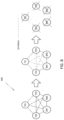
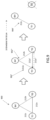
- FIG. 5 illustrates a five-node distributed database system 500 with a chorus group of five nodes TE1, TE2, TE3, SM1, and SM2 that experiences four link failures.
- the four link failures occur between TE1 and SM1 (link 212c), TE1 and SM2 (link 212h), TE2 and TE3 (link 212g), and TE3 and SM1 (link 212j).
- These failures yield several fully connected components, but only one with at least three nodes: ⁇ TE2, SM1, SM2 ⁇ , shown at right.
- Nodes TE1 and TE3 remain partially connected to the distributed database but cannot communicate directly with every other node in the distributed database.
- nodes TE1 and TE3 fail, thereby leaving ⁇ TE2, SM1, SM2 ⁇ as the winning fully connected component 404'.
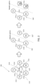
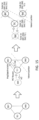
- FIG. 6 illustrates how the partial connectivity case of FIG. 5 cannot be addressed using a rotating leader model methodology.
- five nodes TE1, TE2, TE3, SM1, and SM2 form a group under Step 1 (left). In Step 1, all of these nodes can communicate with each other without interruption. However, as show in Step 2 (right), failures occur in the communication links between TE1 and SM1 (link 212c), TE1 and SM2 (link 212h), TE2 and TE3 (link 212g), and TE3 and SM1 (link 212j). These failures interrupt direct communication between TE1 and SM1, between TE1 and SM2, between TE2 and TE3, and between TE3 and SM1.
- SM1 is the current leader just prior to the network failure. Based on the rotating leader methodology following the link failures, SM1 continues to assume that it is the leader since it receives heartbeat messages from TE2 and SM2. TE1 rotates the leadership to TE2 because of the link failure between TE1 and SM1 (link 212c) owing to which TE1 does not receive heartbeat messages from SM1. In a similar fashion, TE3 rotates the leadership to TE1 because of the link failure between TE3 and SM1 (link 212j).
- SM1, TE2, and TE1 take leadership (not necessarily in that order) in quick succession, but TE1 is not connected to SM1 or SM2 so it doesn't even know whether SM1 is connected to SM2 or not. This rotating leadership makes it difficult to resolve the failure(s).
- leader-less failure resolution processes described herein handle all of these partial connectivity cases in a reliable fashion and thus are improvements over leader-based failure resolution methods.
- FIG. 7 illustrates a distributed database system 700 with a chorus group of five nodes that have three link failures: one between TE1 and SM1 (link 212c), another one between TE2 and TE3 (link 212g), and another one between SM1 and TE3 (link 212j).
- link failures yield fully connected components ⁇ TE1, TE2, SM2 ⁇ , ⁇ TE2, SM1, SM2 ⁇ , and ⁇ TE1, SM2, TE3 ⁇ ; nodes TE1 and TE2 are partially connected.
- Each of these three fully connected components includes more than half the number of nodes in the chorus group before the link failures. Further, these three fully connected majority groups are of the same size.
- the nodes implement a tie-breaking process, such as lexicographic ordering, to identify a winning fully connected component 704'.
- a tie-breaking process such as lexicographic ordering
- ⁇ TE2, SM1, SM2 ⁇ is the winning fully connected component 704' (decided by the tie-breaking process). Therefore, nodes TE1 and TE3 fail themselves to resolve the network failure.
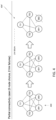
- FIG. 8 illustrates a distributed database system 800 chorus group of five nodes TE1, TE2, TE3, SM1, and SM2.
- five link failures occur: between TE1 and SM1 (link 212c), between TE1 and SM2 (link 212h), between TE2 and TE3 (link 212g), between TE2 and SM2 (link 212i), and between TE3 and SM1 (link 212j).
- there are five fully connected group of nodes following these failures each of which are of a size of two nodes. This is less than more than half the number of nodes in the chorus group before the link failures. Therefore, all of the nodes fail themselves since there are no fully connected majority group after the link failures.
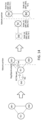
- FIG. 9 illustrates a special case of the partial connectivity, where a (unidirectional) link failure(s) permits a node or a set of nodes to communicate with a subset of other nodes in one direction but not the other.
- a (unidirectional) link failure(s) permits a node or a set of nodes to communicate with a subset of other nodes in one direction but not the other.
- three nodes TE1, TE2, and SM1 in the distributed database system 900 form a chorus group.
- TE1 and TE2 link 212a
- TE2 can send messages to TE1 (link 212a') but TE1 cannot send messages to TE2 (link 212a'').
- This unidirectional link failure (similar to the bidirectional link failure between TE1 and TE2) causes the creation of fully connected components 902' ⁇ TE1, SM1 ⁇ and 902" ⁇ TE2, SM1 ⁇ . Since the two sets of fully connected components are of the same size and include more than half the number of nodes (i.e., 2 of the 3 total nodes) that were up before the link failure, the nodes implement a tie-breaking process to determine the winning fully connected component 904'. In this example, ⁇ TE1, SM1 ⁇ is the winning fully connected component 904' (decided by the tie-breaking process presented above). Therefore, nodes TE1 and SM1 stay up and node TE2 fails itself.
- Case D The process 100 also ensures that a distributed database system should not split into multiple majority groups due to network failures during membership changes.
- a membership change refers to a new node joining the distributed database system or an existing node of the distributed database system leaving the distributed database system.
- FIG. 10 illustrates an example of case D.
- the chorus 1000 starts with three nodes TE1, SM1 and SM2.
- Two nodes TE2 and TE3 try to join the chorus 1000. While they are in the process of joining, a network partition happens, separating the distributed database into fully connected components 1002' ⁇ TE2, TE3, TE1 ⁇ and 1002" ⁇ SM1, SM2 ⁇ .
- Both groups can stay up because the members of group ⁇ TE2, TE3, TE1 ⁇ think that they are part of the chorus ⁇ TE2, TE3, TE1, SM1, SM2 ⁇ and so form a majority, and the members of group ⁇ SM1, SM2 ⁇ think that they are part of the chorus ⁇ TE1, SM1, SM2 ⁇ and so they also form a majority.
- the process 100 ensures that only one group stays up. Put differently, the process 100 ensures that both ⁇ TE2, TE3, TE1 ⁇ and ⁇ SM1, SM2 ⁇ do not stay up simultaneously.
- the failure resolution processes are leaderless processes.
- each node identifies its suspect list, exchanges connectivity information (its own and optionally that of other nodes) with other nodes, and then makes a failure resolution decision.
- the process makes the nodes communicate and exchange connectivity information in such a way that, upon the end of the communication phase of the process, each node should have enough connectivity information about other nodes in its partition to ensure that all nodes within a partition arrive at the same failure resolution decision(s). Any new network failure events that happen while the protocol is in progress causes all nodes to restart the protocol.
- an inventive failure resolution process can include two phases: phase 1, during which each node gathers information about the suspect lists/connectivity of other nodes; and phase 2, during which each node makes a failure resolution decision (e.g., to fail itself) based on the information it gathered during phase 1.
- each node participates in at most two rounds of coordinated broadcasts.
- These coordinated broadcasts of suspect list include exchanging the connectivity information/suspect lists among nodes within a partition.
- each node does one coordinated broadcast.
- each node does two coordinated broadcasts. Two rounds of coordinated broadcasts are enough for all nodes to agree on group membership change in cases A, B, and C.
- the chorus includes n fully connected nodes.
- a network failure event happens.
- Each node goes through the following protocol in order to resolve the network failure event.
- Each node prepares its suspect list (the suspect list could be an empty list, which can happen if a node is (or at least thinks it is) fully connected to all other nodes after the network failure event).
- Phase 1 Each node does (n-1) rounds of coordinated broadcasts in order to gather information about the suspect lists/connectivity of other nodes. In round 1, each node sends its suspect list to its neighbor nodes and waits until it receives the suspect lists of its neighbor nodes. In rounds 2 through (n-1), each node sends the suspect lists of other nodes that it received in the previous round to its neighbors and waits until it receives such information from its neighbors.
- Each node has now received the connectivity information of all other nodes in its partition (since the chorus includes n nodes, nodes doing (n-1) rounds of broadcasts the way described above ensures that each node obtains the connectivity information of all other nodes in its partition).
- Each node prepares the connectivity graph for its partition and finds a fully connected component of maximum size (or a maximum clique) of the connectivity graph. If there is more than one such fully connected component, then the node chooses one fully connected component as the winning fully connected component, decided by a tie-breaking process (e.g., based on the lexicographic order of unique identifiers for the nodes in the fully component). If the winning fully connected component size is at least (n / 2 + 1) and if the node is a member of the winning fully connected component, then the node decides to stay up (and exits the protocol); else, the node fails itself.
- a tie-breaking process e.g., based on the lexicographic order of unique identifiers for the nodes in
- Optimization 1 This is an optimization that is applicable in case of scenarios covered by case A (in the section above). This is based on the observation that if a network failure event divides a database into disjoint groups of fully connected nodes then the suspect lists of all nodes within a group/partition are going to be the same. For example, consider FIG. 2 . In FIG. 2 , nodes TE1, TE2, and SM1 suspect TE3 and SM2, and nodes TE3 and SM2 suspect TE1, TE2, and SM1.
- the node After the first round of coordinated broadcasts during phase 1, if the suspect list of a node matches with the suspect lists of all its neighbors, then the node can infer that (a) it is part of a fully connected component and (b) can identify the size of the fully connected component (which is equal to the chorus size minus the size of its suspect list). Therefore, all nodes can agree on membership change after the first round of broadcast during phase 1.
- Optimization 2 This is an optimization that is applicable mainly in cases B and C above and partly in case A.
- all nodes participate in (n-1) rounds of coordinated broadcasts. This makes each node aware of the connectivity information of all other nodes in its partition. But does each node really need to know the connectivity information of all other nodes in its partition in order to arrive at an optimal failure resolution decision?
- Category (M) includes nodes that suspect less than n / 2 other nodes; and category (N) includes nodes that suspect more than n / 2 nodes. Nodes that suspect more than n / 2 may fail themselves immediately rather than broadcast suspect lists because they cannot be part of a winning fully connected component.
- nodes TE2, SM1 and SM2 fall in category (M) and nodes TE1 and TE3 fall in category (N).
- category (M) does a node in category (M) need to know about the connectivity information of other nodes in category (M) in order to make an optimal failure resolution decision? Yes.
- a node in category (M) can form a fully connected component of size at least (n / 2 + 1) together with other nodes in category (M), and knowing about the connectivity information of other nodes in category (M) helps it identify (a) whether it is a part of a fully connected component of size at least (n / 2 + 1), (b) all fully connected components of size at least (n / 2 + 1), and (c) whether it is a part of the winning fully connected component. Does a node in category (M) need to know about the connectivity information of nodes in category (N) in order to make an optimal failure resolution decision? No.
- a node in category (M) can never form a fully connected component of size at least (n / 2 + 1) together with a node in category (N), which in turn is because nodes in category (N) suspect more than (n / 2) other nodes.
- category (N) does a node in category (N) need to know about the connectivity information of nodes in category (M) and category (N) in order to make an optimal failure resolution decision? No. This is because a node in category (N) suspects more than (n / 2) other nodes and so can never form a fully connected component of size at least (n / 2 + 1) with any other node(s). Making the connectivity information of all other nodes will help a node in category (N) know which other nodes will stay up but doesn't change the fact that that node cannot form a fully connected component of size at least (n / 2 + 1) with other nodes.
- Failing nodes in category (N) doesn't affect the connectivity between the nodes in category (M) (that is, nodes of category (M) do not become disconnected because of the failure of nodes of category (N)) because any two nodes in category (M) are either connected to each other directly or by another node of category (M). Thus, failing the category (N) nodes shouldn't affect the optimality of the failure resolution outcome.
- the optimization basically makes nodes of category (M) reach a consensus on the failure resolution outcome and makes the nodes of category (N) follow that outcome.
- each node that starts phase 1 is connected to at least (n / 2) other nodes, so the diameter of the connectivity graph (i.e., the maximum distance between any two nodes in the connectivity graph) is at most 2. Therefore, only two rounds of broadcasts are needed in order for each node that starts phase 1 to know about the connectivity of each other node that starts phase 1.
- the diameter of the connectivity graph is at most 2 because each node in phase 1 is connected to at least n / 2 other nodes, so any two nodes are separated by at most one node.
- Each node goes through the following protocol to resolve the network failure.
- Each node prepares its suspect list (note: the suspect list could be an empty list, which can happen if a node is (or thinks it is) fully connected to all other nodes after the network failure event).
- Phase 0 Each node checks if it suspects more than (n-1 / 2) other nodes. If so, the node fails itself. (Other nodes may hear about this failure while they are in phase 1. If so, those nodes restart the protocol and start from phase 0 again.)
- Phase 1 Each node sends its suspect list to its neighbor nodes and waits until it receives the suspect lists of its neighbor nodes. As mentioned above, if one or more of a node's neighbors have failed in phase 0, the node may hear about those failures while it is waiting for its neighbors' suspect lists. On hearing about any such failure(s), the node restarts the protocol and starts from phase 0 again. This cause other nodes to restart the protocol too. Similarly, if a neighbor node restarts the protocol, the nodes start from phase 0 again. Also, as mentioned above, this node does not start failover for any failed nodes at this stage (i.e., it keeps every node in its chorus for purposes of determining the winning fully connected component). This is true even for multiple rounds of phase 0.
- Each node checks if its suspect list is same as the suspect lists of all its neighbor nodes. If the node's suspect list matches the suspect lists of all its neighbor nodes, this indicates that the node is fully connected with its neighbor nodes. This scenario is covered in case A above (e.g., FIG. 2 ). Since each node that starts phase 1 is connected to at least (n / 2) other nodes, the node's neighbor list size can be at least (n / 2) (the node together with its neighbors form a group including at least (n / 2 + 1) nodes). The node decides to stay up and exits the protocol.
- the node's suspect list doesn't match with the suspect list of at least one of its neighbors: it indicates that the node is not fully connected with all other nodes in its partition. This scenario is covered in cases B and C above (e.g., FIGS. 3-9 ). Such a node cannot decide whether to stay up or not based on the information it has received in round 1. Therefore, it implements phase 1, round 2.
- Phase 1, round 2 Each node sends the suspect lists of other nodes that it received in round 1 to its neighbors and waits until it receives such the suspect lists of its neighbors' neighbors from its neighbors.
- Each node has now received the connectivity information of all other nodes in its partition.
- Each node prepares the connectivity graph for its partition and finds the largest fully connected component with at least (n / 2 + 1) nodes (or a maximum clique of size at least (n / 2 + 1)) of the connectivity graph. If there is more than one fully connected component (e.g., as in FIG. 7 ) then the node chooses one fully connected component as a winning fully connected component, decided by the tie-breaking process (e.g., lexicographic order) in order to make failure resolution deterministic. If the node is a member of the winning fully connected component then the node decides to stay up (and exits the protocol); else, the node fails itself.
- the tie-breaking process e.g., lexicographic order
- node failures may also happen while the nodes in the distributed database system are resolving a network failure.
- the protocol causes the nodes to restart from phase 0 while keeping the failed nodes as members of the chorus until phase 2 (by not running failover for the failed nodes, thereby stopping the remaining nodes from removing the failed nodes from their node lists).
- retaining the failed nodes as members of the chorus until phase 2 ensures correctness-the outcome of the failure resolution is a fully connected set having at least (n / 2 + 1) nodes, where n includes nodes that have failed, so there can be only one such set that stays up after phase 2.
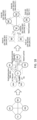
- FIG. 12 is a flowchart illustrating an optimized process 1200 to resolve network failures. Each node follows the same process, so the flowchart shows the process 1200 from the perspective of a single node.
- the process 1200 is detailed in terms of stages.
- Stage 0 The initial stage. At 1202, the node is fully connected to all other nodes in the chorus. Detection of suspect nodes, either locally or remotely, causes the node to move to stage 1.
- Stage 1 At 1210, the node waits one ping (heartbeat) cycle for additional ping (heartbeat) timeouts to happen, prepares its suspect list, consumes any suspect list messages it has received, and then enters stage 2.
- Stage 2 At 1220, the node checks if it suspects more than (n-1 / 2) other nodes (where n is the number of nodes in the chorus). If so, at 1299, the node fails itself. If not, the node checks if it has any new suspects since preparing its suspect list in stage 1. Also, the node checks if any of its neighbors have detected new suspects and so have restarted the protocol. Each node may assign a number, called protocolIterationNumber, for each iteration of the process 1200 that it runs. Each node sets this number in the suspect list messages that it sends and compares its local protocolIterationNumber with the protocolIterationNumber in the suspect lists that it receives from other nodes.
- protocolIterationNumber a number, called protocolIterationNumber
- a node determines that its protocolIterationNumber is lower than a neighbor's protocolIterationNumber, it determines that its neighbor has restarted the process and goes back to stage 1. Otherwise, the node enters stage 3. (If a node's protocolIterationNumber is higher than a neighbor's protocolIterationNumber, the node has restarted the protocol (possibly due to finding new suspects), which should cause the neighbor to restart the protocol too.)
- Stage 3 At 1230, the node broadcasts its round 1 suspect list to its neighbor nodes.
- the node may detect new suspects or may hear that one or more of its neighbors detected new suspects while it is waiting for round 1 suspect list messages at 1232. If so, the node stops waiting for any more responses, and goes back to stage 1.
- the nodes receives round 1 suspect list messages from all of its neighbor nodes. If the node does not receive responses from any of its neighbors in a timely manner (e.g., within a predetermined period), then at 1236, the node marks such neighbors as suspects and goes back to stage 1.
- the node If the node receives a round 1 suspect list with a higher protocolIterationNumber than its protocolIterationNumber, then at 1238, the node returns to the beginning of stage 1. On receiving round 1 responses from all of its neighbors, the node enters stage 4.
- Stage 4 At 1240, if the node's suspect list matches with the suspect lists of all its neighbors, then the node determines that it is fully connected with its neighbor nodes (e.g., as in FIG. 2 ). Since each node that starts stage 3 is connected to at least (n / 2) other nodes, the node's neighbor list size can be at least (n / 2) ( i.e., the node and its neighbors form a fully connected component or group including at least (n / 2 + 1 ) nodes). At 1201, the node decides to stay up, evicts the suspect nodes, and exits the process 1200.
- the node's suspect list doesn't match the suspect lists of at least one of its neighbors, then the node is not fully connected with all other nodes in its partition (e.g., as in FIGS. 3-9 ).
- the node cannot decide whether to stay up or fail based on the information it received in round 1, so the node enters stage 5, which involves broadcasting round 2 suspect list messages at 1250.
- Stage 5 At 1250, the node broadcasts its round 2 suspect list, which includes its original suspects plus its neighbor nodes' suspects, to its neighbor nodes and waits till it receives round 2 suspect list messages from all its neighbor nodes.
- the node may receive round 2 suspect list messages from the other nodes any time after it broadcasts its round 1 suspect list message at 1230. The node accumulates these round 2 suspect list messages.
- the node if a new network failure happens, if the node receives a round 1 message from another node, or if the node hears about the failure of another node, then the node goes back to stage 1. Upon going back to stage 1, the node discards all accumulated round 2 suspect list messages.
- the node distinguishes between these two types of messages based on the protocolIterationNumber in the round 1 and round 2 suspect list messages. Put differently, the messages based on the protocolIterationNumber include the protocolIterationNumber and the round number.
- the node upon receiving round 2 suspect list messages from all its neighbor nodes the node enters stage 6. If a new network event happens or if the node hears about the failure of another node after the node broadcasts its round 2 suspect list message, then the failure resolution decision may not be an optimal one. There are at least two possible cases: in case (a), the node has already received the round 2 message from the new suspect node or the failed node; and in case (b), the node has not received the round 2 message from the new suspect or from the failed node.
- the node could move on to stage 6, do the failure resolution for the current network event, and then handle the new network event by restarting the protocol, or go back to stage 1 (without resolving the current network event) and then restart the process 1200. (which would then resolve both the current and new network failures).
- the node does not receive round 2 message from the new suspect or the failed node, so the node goes back to stage 1. But there is no guarantee that the other nodes will also go back to stage 1 before completing stage 6 (because they may have received round 2 message from the new suspect or the failed node).
- the outcome of failure resolution could be sub-optimal (that is, the surviving set will be smaller than what it could have been, but there will still be only one surviving set) in this case. But moving this node to stage 1 does not stop other nodes from making progress because this node has already sent its round 2 message.
- Stage 6 the node prepares the connectivity graph for its partition and finds the largest fully connected component of size at least (n / 2 + 1) (or a maximum clique of size at least (n / 2 + 1) ) of the connectivity graph. If there is more than one such component then the node chooses one from among them, decided by the tie-breaking process, as a winning fully connected component. If the node is a member of the winning fully connected component, then at 1201, the node decides to stay up and evicts nodes that are not part of the winning fully connected component. If not, at 1299, the node fails itself.
- any node in the distributed database system can start the failure resolution protocol (e.g., process 1200 in FIG. 12 ) in response to detecting one or more suspect nodes. And any new network failure events that happen during the execution of a failure resolution protocol triggers a restart of the protocol.
- the nodes In order to enable nodes to detect whether a suspect list message (either round 1 or round 2) they receive belongs to the current invocation of the protocol or the following invocation due to the restart of the protocol (or even the previous invocation of the protocol in case of nodes that have restarted the protocol), the nodes associate a number, called protocolIterationNumber, with each invocation of the failure resolution protocol.
- Each node maintains its local protocolIterationNumber and sets this number in the suspect list messages that it sends, and each node compares its local protocolIterationNumber with the protocolIterationNumber in the suspect list messages that it receives. If the numbers match, the node infers that the suspect list message that it received corresponds to the current invocation of the protocol. If the protocolIterationNumber in the suspect list message that it received is higher than its own protocolIterationNumber, then the node infers that the sender has initiated a restart of the protocol (and so restarts the protocol). And if the protocolIterationNumber in the suspect list message that it received is lower than its own protocolIterationNumber, then the node infers that the sender is still running the previous iteration of the protocol and so ignores the message.
- Each node can maintains its local protocolIterationNumber in the following way:
- Unidirectional link failures such as case D presented above ( FIG. 10 ) can be resolved by handling them as bidirectional link failures (i.e., by making the nodes on both sides of a failed link suspect each other). For instance, consider two nodes-node A and node B-in a distributed database system. Assume that node A can send messages to node B, but node B cannot send messages to node A. Since A can send ping messages to node B but does not receive any acknowledgement message from node B, node A begins to suspect node B. At this point, node B does not yet suspect node A. However, since node A begins to suspect node B, it stops sending ping messages to node B. This causes node B to suspect node A, thereby converting a unidirectional link failure to a bidirectional link failure.
- a node sends a MsgPing message (e.g., ping message) and sets Node::lastPingTime for a particular node only if that node has acknowledged the previous MsgPing message.
- MsgPing message e.g., ping message
- Node::lastPingTime e.g., ping message
- a network partition splits the chorus into a majority group ⁇ SM1, SM2 ⁇ and a minority group ⁇ TE1 ⁇ . But the minority group ⁇ TE1 ⁇ together with new nodes ⁇ TE2, TE3 ⁇ forms a majority group ⁇ TE1, TE2, TE3 ⁇ , resulting in two "majority" groups ⁇ TE1, TE2, TE3 ⁇ and ⁇ SM1, SM2 ⁇ .
- this process may affect the availability of the system (depending on the number of nodes, odd or even, in the current chorus, number of nodes that are trying to join the chorus, number of nodes in the chorus that are aware of the new node(s) at the time of the network failure, etc.).
- This process can also piggyback on processes for requesting fragments of data in the distributed database (the originator sending available fragments, peers sending acknowledgments to the originator, and the originator sending the complete data to the requester) in order to make the current chorus members agree on a new node joining the chorus.
- This process involves the following change to the failure resolution process 1200 in FIG. 12 in order for nodes to agree on chorus size during the node join process:
- Nodes exchange their complete connectivity information (that is, their neighbor node lists together with their suspect node lists) during the round 1 and round 2 broadcasts.
- the nodes compare their suspect and neighbor node lists with their neighbors' suspect and neighbor node lists in response to receiving round 1/round 2 messages. If a node finds that its neighbor knows about n j nodes that it doesn't know about, then it increments its chorus size by n j and restarts the process.
- This process can ensure correctness: if a new node(s) cannot get into the node lists of all nodes in a chorus due to a network partition, then that new node(s) fails itself during failure resolution. If n is the number of nodes in a chorus and n j is the number of nodes that are trying to join the chorus at the same time but that cannot get into the node lists of all n nodes due to a network partition, then n j nodes (the new nodes) fail themselves while running the process irrespective of their partition. So a maximum of n nodes check if they are in a majority partition, after round 1, in order to decide whether to stay up or not.
- nodes in each partition run with a chorus size s ( n ⁇ s ⁇ n + n j ) and that there are a maximum of n nodes in the chorus after round 1, at most one partition can form a majority group, and that ensures correctness.
- a chorus includes nodes A, B, and C, and A is the chairman/leader of a fragment of the distributed database (e.g., fragment "master catalog").
- New nodes D and E try to join the chorus at the same time.
- Node A sends available messages for D and E to B and C.
- B and C don't receive ping messages from A, suspect A, and start the protocol.
- B and C haven't applied the available messages from A (yet), so start the protocol with chorus members ⁇ A, B, C ⁇ .
- B and C apply the available messages, send acknowledgment messages to A, and then the network split happens.
- the master catalog on D and E becomes complete, so A, D, and E start the protocol with chorus members ⁇ A, B, C, D, E ⁇ .
- Both groups ⁇ A, D, E ⁇ and ⁇ B,C ⁇ think that they can form a majority group.
- the following extension can prevent such a situation: After applying an available message (or after sending the master catalog to a new node, in the case of the chairman node), a node restarts the failure resolution protocol (if one is in progress), which causes the node to invalidate its cached suspect and neighbor lists and recompute them with a larger chorus size.
- FIGS. 13-18 illustrate some example failure scenarios and how the inventive failure resolution processes handle them.
- SM3 requests and receives the master catalog from TE1 (the chairman of the master catalog) and a network partition happens before TE1 sends MsgObjectAvailable (e.g., a message that tells the receiver node that the sender node is joining the distributed database system) to SM1 and SM2. All nodes, including SM3, start the resolution protocol. SM3 and TE1 suspect nodes SM1 and SM2, and SM1 and SM2 suspect TE1 (SM1 and SM2 don't know about SM3).
- MsgObjectAvailable e.g., a message that tells the receiver node that the sender node is joining the distributed database system
- SM3 fails because it is still in the process of joining the chorus (it hasn't received complete from TE1), TE1 fails (in phase 0) because it suspects two nodes in the chorus ⁇ SM1, SM2, SM3, TE1 ⁇ , and SM1 and SM2 stay up because they form a majority in the chorus ⁇ SM1, SM2, TE1 ⁇ .
- Scenario (B) A variation of scenario (A).
- a network partition happens separating the new node and the entry node (the originator of the master catalog) from the rest of the nodes.
- SM3 requests and receives the master catalog from TE1 (the chairman of the master catalog), SM1 receives MsgObjectAvailable from TE1, and a network partition happens before SM2 receives MsgObjectAvailable from TE1.
- SM3 fails because it is still in the process of joining the chorus (it hasn't received final confirmation of joining from TE1), TE1 and SM1 fail (in phase 0) because they suspect two nodes in the chorus ⁇ SM1, SM2, SM3, TE1 ⁇ .
- SM3 requests and receives the master catalog from TE1 (the chairman of the master catalog), SM1 receives MsgObjectAvailable from TE1, and a network partition separates SM2 from the rest of the nodes before SM2 receives MsgObjectAvailable from TE1.
- SM3 fails because it is still in the process of joining the chorus (it hasn't received complete from TE1).
- SM2 fails because it is in a minority partition in the chorus ⁇ SM1, SM2, TE1 ⁇ .
- TE1 and SM1 start the protocol, don't receive a (round 1) response from SM3, eventually suspect SM3, and then fail themselves.
- SM4 requests and receives the master catalog from TE1 (the chairman of the master catalog), SM1 and SM3 receive MsgObjectAvailable from TE1, and a network partition happens separating SM2 from the rest of the nodes.
- SM4 fails because it is still in the process of joining the chorus.
- SM2 fails because it is in a minority partition in the chorus ⁇ SM1, SM2, SM3, TE1 ⁇ .
- TE1, SM1, and SM3 stay up because they form a majority group in the chorus ⁇ SM1, SM2, SM3, SM4, TE1 ⁇ .
- the group ⁇ TE1, SM1, SM3 ⁇ was a majority in the original chorus ⁇ TE1, SM1, SM2, SM3 ⁇ and is still a majority in the new chorus ⁇ TE1, SM1, SM2, SM3, SM4 ⁇ .
- SM4 and SM5 request and receive the master catalog from TE1 (the chairman of the master catalog), SM1 and SM3 receive MsgObjectAvailable from TE1 for both SM4 and SM5, and a network partition separates SM2 from the rest of the nodes.
- SM4 and SM5 fail because they are still in the process of joining the chorus
- SM2 fails because it is in a minority group in the chorus ⁇ SM1, SM2, SM3, TE1 ⁇ .
- TE1, SM1, and SM3 also fail because they form a minority group in the chorus ⁇ SM1, SM2, SM3, SM4, SM5, TE1 ⁇ .
- the nodes TE1, SM1, and SM3 that stayed up in scenario (H) fail here because there are two nodes trying to join the chorus, which causes these nodes to become a minority group in the new chorus.
- a chorus with n nodes can tolerate a network partition that separates a maximum of (n - (n / 2 + 1)) nodes from the rest of the nodes in the chorus (or the simultaneous failure of up to (n - (n / 2 + 1 )) nodes in the chorus) and still stay up. If a single node is trying to join the chorus, the chorus can tolerate the separation of (n - (n / 2 + 1) - 1) nodes and still stay up if n is odd. For a single new node, the chorus can tolerate the separation of (n - (n / 2 + 1)) nodes and still stay up if n is even.
- TABLE 1 summarizes the failure tolerance of a chorus for various number of nodes in the chorus (n) and various of number of nodes ( n j ) that are trying to join the chorus at the same time: In the TABLE 1 below, there are n j nodes trying to join the chorus at the same time and at least one node in the majority partition has received MsgObjectAvailable for all n j nodes.
- the chorus failure tolerance in this configuration is zero, so a network partition (or any node failure) while a new node is joining (with at least one of the nodes receiving MsgObjectAvailable) causes the entire chorus to fail.
- Scenario A is not captured by TABLE 1 because none of the nodes in the majority group in Scenario A received MsgObjectAvailable.
- the chorus failure tolerance in Scenario H is one. Since the chorus has a single node in the minority partition, the chorus stays up.
- the chorus failure tolerance in this configuration is zero, so a network partition while the nodes are joining causes the entire chorus to fail.
- the present section discusses handling one or more node failures (or shutdowns) while a distributed database system is resolving a network failure.
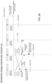
- the process of resolving a network failure event involves nodes exchanging failure detection messages, nodes deciding whether to stay up or not based on the exchanged messages, and the nodes that decide to stay up running failover for the suspect nodes. This process is illustrated in FIG. 19 .
- the chorus includes members ⁇ A, B, C, D ⁇ .
- a network partition separates ⁇ A, B, C ⁇ from D.
- Nodes A, B, and C suspect node D exchange failure detection messages, decide to stay up, and run failover for D.
- Node D suspects nodes A, B, and C starts the failure resolution protocol, and fails itself.
- node failures cause neighbors of the failed nodes to start (or restart) the failure resolution protocol, agree on evicting the failed nodes, and evict the failed nodes from the chorus. If node failures happen while a distributed database system is in the process of resolving a network failure event, the failed nodes may show up as new suspects for the neighbors of the failed nodes. This can cause the neighbors to restart the protocol. Therefore, there is no special mechanism to handle node failures during partition resolution. Instead, the processes described herein ensure that the nodes that start/restart the failure resolution protocol in response to node failures agree on chorus membership.
- the neighbors will restart the failure resolution process with an updated suspect list.
- This updated suspect list is the union of the suspect nodes caused by the network failure and the failed nodes. The neighbors will stay up if they form a majority group based on the updated suspect list.
- a network partition separates ⁇ A, B, C ⁇ from D, and node C fails while the nodes are exchanging messages. Nodes A and B restart the protocol upon suspecting C. A and B fail because they don't form a majority group in the chorus ⁇ A, B, C, D ⁇ .
- a node fails while the nodes are running failover (removing failed nodes from the chorus membership list), its neighbors may have started or completed failover for other suspect nodes. As a result, the neighbors may have removed one or more suspect nodes from their node lists, so the neighbors may not agree on chorus membership/chorus size upon start/restart of the protocol.
- the chorus includes members ⁇ A, B, C, D ⁇ .
- a network partition separates ⁇ A, B, C ⁇ from D.
- Nodes A, B, and C start the protocol, exchange failure detection messages, and decide to stay up.
- Node A, B, and C start failover for node D.
- node C fails. This causes A to suspect C and to start the node failure process with chorus ⁇ A, B, C ⁇ and suspect list ⁇ C ⁇ . It also causes B to start the node failure process with chorus ⁇ A, B, C, D ⁇ and suspect list ⁇ C, D ⁇ .
- a and B do not agree on chorus membership.
- n is the number of nodes in a majority partition
- f is the number of failed nodes
- e is the number of evicted nodes for which failover is being run
- the nodes in the partition will stay up if (n - f) ⁇ (s / 2 + 1) , where (n ⁇ s ⁇ n + e) .
- the process can be further extended as following: the nodes exchange their complete connectivity information (i.e., their neighbor node lists together with their suspect node lists) during rounds 1 and 2 of the broadcasts. Then the nodes compare their suspect and neighbor node lists with their neighbors' suspect and neighbor node lists. If a node finds that its neighbor knows about n j nodes that it doesn't know about, then it increments its chorus size by n j and restarts the process. Later, if the node's neighbor restarts the process by removing r j nodes from its chorus list, then the node decrements its chorus size by r j and restarts the process.
- each node can run the failure resolution process based on the chorus membership decided by that node's master catalog node list. The process ensures that all nodes arrive at a correct result as long as any nodes whose membership isn't agreed upon on are either failed before the process starts or failed during the process.
- n + n j be the number of nodes in a chorus.
- n is the number of nodes whose master catalog is complete
- n j is the sum of the number of failed nodes and the number of nodes that will fail (as in the node failure case; the master catalog of these nodes might or might not be complete at the time they failed) or the number of new nodes that will fail once they start the failure resolution protocol (as in the node join case; the master catalog of these nodes won't be complete at the time they fail).
- s be the size of the master catalog node list on nodes that participate in the failure resolution protocol: n ⁇ s ⁇ n+ n j . Note that s might not be the same on all nodes participating in the failure resolution protocol.
- nodes within a partition may conclude that they are not in a majority group. These nodes fail during stage 2 of the process ( FIG. 12 ), causing the rest of the nodes within that partition to restart the process. But if the rest of the nodes, on restart of the process, can conclude that they are in a majority group, then that can be enough to make that fully connected component the winning fully connected component .
- failure detection cannot be triggered. This is achieved by modifying the failure resolution process not to treat manually shut-down nodes as suspect nodes.
- a node On receiving a shutdown request from the admin layer, a node broadcasts a message node state (MsgNodeState) message indicating that it is shutting down (e.g., with node state NODE_STATE_SHUTTING_DOWN).
- An admin layer in a distributed database system is a layer of nodes via which a user can interact with the distributed database.
- the admin layer can track nodes in the distributed database system and can facilitate interaction between the user and the nodes in the distributed database system. For example, when a user wants to shut down a node, the user can give the shutdown command to the admin layer, which then sends the shutdown message to the node specified by the user.
- the process relies on at least one chorus member receiving this node state message from the node that is shutting down.
- a chorus includes nodes A, B, C, D, and E.
- the user shuts down node E and at about the same time a network partition separates ⁇ A, B ⁇ from ⁇ C, D ⁇ .
- a network partition separates ⁇ A, B ⁇ from ⁇ C, D ⁇ .
- node A starts the protocol with chorus ⁇ A, B, C, D, E ⁇ , suspect list ⁇ C, D ⁇ , and shutting-down node list ⁇ E ⁇ and sends a round 1 failure detection message to B.
- inventive concepts may be embodied as one or more methods, of which an example has been provided.
- the acts performed as part of the method may be ordered in any suitable way. Accordingly, embodiments may be constructed in which acts are performed in an order different than illustrated, which may include performing some acts simultaneously, even though shown as sequential acts in illustrative embodiments.
Landscapes
- Engineering & Computer Science (AREA)
- Theoretical Computer Science (AREA)
- Computer Networks & Wireless Communication (AREA)
- Signal Processing (AREA)
- General Physics & Mathematics (AREA)
- Physics & Mathematics (AREA)
- General Engineering & Computer Science (AREA)
- Databases & Information Systems (AREA)
- Computing Systems (AREA)
- Data Mining & Analysis (AREA)
- Environmental & Geological Engineering (AREA)
- Quality & Reliability (AREA)
- Computer Security & Cryptography (AREA)
- Hardware Redundancy (AREA)
- Locating Faults (AREA)
- Data Exchanges In Wide-Area Networks (AREA)
Claims (15)
- Verfahren (100; 1200) zum Beheben eines Fehlers in einer verteilten Datenbank (200; 300; 400; 500; 700; 800; 900), wobei die verteilte Datenbank eine Vielzahl von Knoten (TE1, TE2, TE3, SM1, SM2) enthält, wobei jeder Knoten in der Vielzahl von Knoten direkt mit jedem anderen Knoten in der Vielzahl von Knoten verbunden ist, wobei das Verfahren als Reaktion auf das Erfassen des Fehlers Folgendes umfasst:
an einem ersten Knoten in der Vielzahl von Knoten:Identifizieren (102; 1202, 1210) eines verdächtigen Knotens in der Vielzahl von Knoten, wobei der verdächtige Knoten ein Knoten in der Vielzahl von Knoten ist, der als Ergebnis des Fehlers nicht mehr mit dem ersten Knoten verbunden ist;Übertragen (104; 1230) einer ersten Liste verdächtiger Knoten an Nachbarknoten in der Vielzahl von Knoten, wobei die erste Liste verdächtiger Knoten den verdächtigen Knoten enthält, wobei die Nachbarknoten Knoten in der Vielzahl von Knoten sind, die nach dem Ausfall direkt mit dem ersten Knoten verbunden bleiben;Empfangen (1234) einer zweiten Liste verdächtiger Knoten von mindestens einem der Nachbarknoten;Bestimmen (106; 1240) von Konnektivitätsinformationen für die Vielzahl von Knoten, basierend mindestens teilweise auf der ersten Liste verdächtiger Knoten und der zweiten Liste verdächtiger Knoten;Bestimmen (110; 1260), ob der erste Knoten in einer gewinnenden vollständig verbundenen Komponente (204'; 304'; 404'; 704'; 904') der verteilten Datenbank ist, basierend auf den Konnektivitätsinformationen, wobei die gewinnende vollständig verbundene Komponente mehr als die Hälfte der Knoten in der Vielzahl von Knoten enthält und jeder Knoten in dem Knoten der gewinnenden vollständig verbundenen Komponente direkt mit jedem anderen Knoten in dem Knoten der gewinnenden vollständig verbundenen Komponente verbunden ist;als Reaktion auf das Bestimmen, dass der erste Knoten in der gewinnenden vollständig verbundenen Komponente der Vielzahl von Knoten ist, Weiterbetreiben (114; 1201) des ersten Knotens; undals Reaktion auf das Bestimmen, dass der erste Knoten nicht in der gewinnenden vollständig verbundenen Komponente der Vielzahl von Knoten ist, Ausfallenlassen (112; 1299) des ersten Knotens, um den Ausfall zu beheben. - Verfahren nach Anspruch 1, wobei das Senden der ersten Liste verdächtiger Knoten das Senden einer Protokolliterationsnummer enthält, die eine Iteration des vom ersten Knoten aufgerufenen Verfahrens angibt.
- Verfahren nach Anspruch 2, das ferner Folgendes umfasst:
Vergleichen der Protokolliterationsnummer mit einer Protokolliterationsnummer, die mit der zweiten Liste verdächtiger Knoten empfangen wurde. - Verfahren nach Anspruch 2, das ferner Folgendes umfasst:
Serialisieren der Protokolliterationsnummer als Teil eines Hauptkatalogs, wobei der Hauptkatalog eine Liste der Knoten in der Vielzahl von Knoten enthält. - Verfahren nach Anspruch 1, wobei das Bestimmen der Konnektivitätsinformationen am ersten Knoten ferner Folgendes umfasst:Bestimmen eines Konnektivitätsgraphen, basierend mindestens teilweise auf den Konnektivitätsinformationen; undIdentifizieren der gewinnenden vollständig verbundenen Komponente aus dem Konnektivitätsgraphen, und optional, wobei das Identifizieren der gewinnenden vollständig verbundenen Komponente das Bestimmen der gewinnenden vollständig verbundenen Komponente basierend auf einer Größe der gewinnenden vollständig verbundenen Komponente und einer Größe der Vielzahl von Knoten umfasst.
- Verfahren nach Anspruch 1, wobei das Bestimmen, ob der erste Knoten in der gewinnenden vollständig verbundenen Komponente ist, umfasst, an dem ersten Knoten die gewinnende vollständig verbundene Komponente basierend auf den Konnektivitätsinformationen zu identifizieren.
- Verfahren nach Anspruch 6, wobei das Identifizieren der gewinnenden vollständig verbundenen Komponente Folgendes umfasst:Bestimmen einer ersten vollständig verbundenen Komponente (202', 302', 402', 702', 902', 1002') der verteilten Datenbank basierend auf den Konnektivitätsinformationen, wobei jeder Knoten in der ersten vollständig verbundenen Komponente direkt mit jedem anderen Knoten in der ersten vollständig verbundenen Komponente verbunden ist;Bestimmen einer zweiten vollständig verbundenen Komponente (202", 302", 402", 702", 902", 1002") der verteilten Datenbank basierend auf den Konnektivitätsinformationen, wobei die zweite vollständig verbundene Komponente sich von der ersten vollständig verbundenen Komponente unterscheidet, wobei jeder Knoten in der zweiten vollständig verbundenen Komponente direkt mit jedem anderen Knoten in der zweiten vollständig verbundenen Komponente verbunden ist;Bestimmen, dass die erste vollständig verbundene Komponente (i) mehr Knoten als die zweite vollständig verbundene Komponente und (ii) mehr als die Hälfte der Knoten in der Vielzahl von Knoten enthält; undAuswählen der ersten vollständig verbundenen Komponente als die gewinnende vollständig verbundene Komponente.
- Verfahren nach Anspruch 6, wobei das Identifizieren der gewinnenden vollständig verbundenen Komponente Folgendes umfasst:Bestimmen einer ersten vollständig verbundenen Komponente der verteilten Datenbank basierend auf den Konnektivitätsinformationen, wobei jeder Knoten in der ersten vollständig verbundenen Komponente direkt mit jedem anderen Knoten in der ersten vollständig verbundenen Komponente verbunden ist;Bestimmen einer zweiten vollständig verbundenen Komponente der verteilten Datenbank basierend auf den Konnektivitätsinformationen, wobei die zweite vollständig verbundene Komponente sich von der ersten vollständig verbundenen Komponente unterscheidet, wobei jeder Knoten in der zweiten vollständig verbundenen Komponente direkt mit jedem anderen Knoten in der zweiten vollständig verbundenen Komponente verbunden ist;Bestimmen, dass die erste vollständig verbundene Komponente (i) dieselbe Anzahl von Knoten wie die zweite vollständig verbundene Komponente und (ii) mehr als die Hälfte der Knoten in der Vielzahl von Knoten enthält; undAuswählen der ersten vollständig verbundenen Komponente als die gewinnende vollständig verbundene Komponente basierend auf eindeutigen Kennungen der Knoten in der ersten vollständig verbundenen Komponente und der zweiten vollständig verbundenen Komponente.
- Verfahren nach Anspruch 1, das ferner Folgendes umfasst:
Übertragen (1250) der zweiten Liste verdächtiger Knoten von dem ersten Knoten zu mindestens einem Nachbarknoten. - Verfahren nach Anspruch 1, das ferner Folgendes umfasst:Aktualisieren der ersten Liste verdächtiger Knoten, basierend mindestens teilweise auf der zweiten Liste verdächtiger Knoten; undSenden der aktualisierten ersten Liste verdächtiger Knoten von dem ersten Knoten zu den Nachbarknoten.
- Verfahren nach Anspruch 1, wobei der erste Knoten weniger als die Hälfte der Vielzahl von Knoten als verdächtige Knoten identifiziert.
- Verfahren nach Anspruch 1, das ferner Folgendes umfasst:Identifizieren von mehr als der Hälfte der Vielzahl von Knoten als verdächtige Knoten an einem dritten Knoten in der Vielzahl von Knoten; undVerhindern, dass der dritte Knoten den Fehler behebt.
- Verfahren nach Anspruch 1, das ferner Folgendes umfasst:
Verhindern, dass ein dritter Knoten versucht, sich der Vielzahl von Knoten anzuschließen, als Reaktion auf die Erfassung des Fehlers. - Verfahren nach Anspruch 1, wobei der Fehler ein erster Fehler ist, der verdächtige Knoten ein erster verdächtiger Knoten ist, und ferner umfassend, an einem dritten Knoten in der Vielzahl von Knoten:Erfassen eines zweiten Fehlers in der verteilten Datenbank;Identifizieren eines zweiten verdächtigen Knotens in der Vielzahl von Knoten, wobei der zweite verdächtige Knoten ein Knoten in der Vielzahl von Knoten ist, der als Ergebnis des zweiten Fehlers nicht mehr direkt mit dem dritten Knoten verbunden ist;Senden einer dritten Liste verdächtiger Knoten an den ersten Knoten; undNeustarten des Verfahrens durch den ersten Knoten.
- Verteiltes Datenbanksystem (200; 300; 400; 500; 700; 800; 900), das Folgendes umfasst:eine Vielzahl von Knoten (TE1, TE2, TE3, SM1, SM2), wobei jeder Knoten in der Vielzahl von Knoten einen entsprechenden Prozessor und einen entsprechenden Speicher enthält und direkt mit jedem anderen Knoten in der Vielzahl von Knoten verbunden ist, wobei der Prozessor an einem ersten Knoten in der Vielzahl von Knoten dafür konfiguriert ist, einen Fehler in dem verteilten Datenbanksystem durch Folgendes zu beheben:Identifizieren eines verdächtigen Knotens in der Vielzahl von Knoten (102; 1202, 1210), wobei der verdächtige Knoten ein Knoten in der Vielzahl von Knoten ist, der als Ergebnis eines Fehlers in dem verteilten Datenbanksystem nicht mehr mit dem ersten Knoten verbunden ist;Senden (104; 1230) einer ersten Liste verdächtiger Knoten an Nachbarknoten in der Vielzahl von Knoten, wobei die erste Liste verdächtiger Knoten den verdächtigen Knoten enthält, wobei die Nachbarknoten Knoten in der Vielzahl von Knoten sind, die nach dem Ausfall direkt mit dem ersten Knoten verbunden bleiben;Empfangen (1234) einer zweiten Liste verdächtiger Knoten von mindestens einem der Nachbarknoten;Bestimmen (106; 1240) von Konnektivitätsinformationen für die Vielzahl von Knoten, basierend mindestens teilweise auf der ersten Liste verdächtiger Knoten und der zweiten Liste verdächtiger Knoten;Bestimmen (110; 1260), ob der erste Knoten in einer gewinnenden vollständig verbundenen Komponente (204'; 304'; 404'; 704'; 904') der verteilten Datenbank ist, basierend auf den Konnektivitätsinformationen, wobei die gewinnende vollständig verbundene Komponente mehr als die Hälfte der Knoten in der Vielzahl von Knoten enthält und jeder Knoten in dem Knoten der gewinnenden vollständig verbundenen Komponente direkt mit jedem anderen Knoten in dem Knoten der gewinnenden vollständig verbundenen Komponente verbunden ist;als Reaktion auf das Bestimmen, dass der erste Knoten in der gewinnenden vollständig verbundenen Komponente der Vielzahl von Knoten ist, Weiterbetreiben (114; 1201) des ersten Knotens; undals Reaktion auf das Bestimmen, dass der erste Knoten nicht in der gewinnenden vollständig verbundenen Komponente der Vielzahl von Knoten ist, Ausfallenlassen (112; 1299) des ersten Knotens, um den Ausfall zu beheben.
Priority Applications (1)
| Application Number | Priority Date | Filing Date | Title |
|---|---|---|---|
| EP25182408.2A EP4604502A3 (de) | 2019-02-01 | 2020-02-03 | Knotenfehlererkennung und -auflösung in verteilten datenbanken |
Applications Claiming Priority (2)
| Application Number | Priority Date | Filing Date | Title |
|---|---|---|---|
| US201962800009P | 2019-02-01 | 2019-02-01 | |
| PCT/US2020/016449 WO2020160557A1 (en) | 2019-02-01 | 2020-02-03 | Node failure detection and resolution in distributed databases |
Related Child Applications (1)
| Application Number | Title | Priority Date | Filing Date |
|---|---|---|---|
| EP25182408.2A Division EP4604502A3 (de) | 2019-02-01 | 2020-02-03 | Knotenfehlererkennung und -auflösung in verteilten datenbanken |
Publications (4)
| Publication Number | Publication Date |
|---|---|
| EP3918355A1 EP3918355A1 (de) | 2021-12-08 |
| EP3918355A4 EP3918355A4 (de) | 2022-10-26 |
| EP3918355B1 true EP3918355B1 (de) | 2025-06-25 |
| EP3918355C0 EP3918355C0 (de) | 2025-06-25 |
Family
ID=71842387
Family Applications (2)
| Application Number | Title | Priority Date | Filing Date |
|---|---|---|---|
| EP25182408.2A Pending EP4604502A3 (de) | 2019-02-01 | 2020-02-03 | Knotenfehlererkennung und -auflösung in verteilten datenbanken |
| EP20749510.2A Active EP3918355B1 (de) | 2019-02-01 | 2020-02-03 | Knotenfehlerdetektion und -auflösung in verteilten datenbanken |
Family Applications Before (1)
| Application Number | Title | Priority Date | Filing Date |
|---|---|---|---|
| EP25182408.2A Pending EP4604502A3 (de) | 2019-02-01 | 2020-02-03 | Knotenfehlererkennung und -auflösung in verteilten datenbanken |
Country Status (5)
| Country | Link |
|---|---|
| US (4) | US11500743B2 (de) |
| EP (2) | EP4604502A3 (de) |
| JP (2) | JP7595014B2 (de) |
| CN (2) | CN117929911A (de) |
| WO (1) | WO2020160557A1 (de) |
Families Citing this family (2)
| Publication number | Priority date | Publication date | Assignee | Title |
|---|---|---|---|---|
| EP4604502A3 (de) | 2019-02-01 | 2025-09-03 | NUODB Inc. | Knotenfehlererkennung und -auflösung in verteilten datenbanken |
| US11983170B2 (en) * | 2020-10-14 | 2024-05-14 | Oracle International Corporation | System and method for transaction continuity across failures in a scale-out database |
Family Cites Families (25)
| Publication number | Priority date | Publication date | Assignee | Title |
|---|---|---|---|---|
| US5884018A (en) * | 1997-01-28 | 1999-03-16 | Tandem Computers Incorporated | Method and apparatus for distributed agreement on processor membership in a multi-processor system |
| US7774469B2 (en) * | 1999-03-26 | 2010-08-10 | Massa Michael T | Consistent cluster operational data in a server cluster using a quorum of replicas |
| US7324438B1 (en) * | 2003-02-13 | 2008-01-29 | Cisco Technology, Inc. | Technique for nondisruptively recovering from a processor failure in a multi-processor flow device |
| US8549180B2 (en) * | 2004-10-22 | 2013-10-01 | Microsoft Corporation | Optimizing access to federation infrastructure-based resources |
| US7765186B1 (en) * | 2005-04-13 | 2010-07-27 | Progress Software Corporation | Update-anywhere replication of distributed systems |
| CN100591042C (zh) * | 2006-07-17 | 2010-02-17 | 华为技术有限公司 | 半分布式p2p网络流量管理方法、系统及设备 |
| WO2009122437A2 (en) * | 2008-03-31 | 2009-10-08 | Tata Consultancy Services Limited | Security in mobile ad hoc networks |
| JP2010182287A (ja) * | 2008-07-17 | 2010-08-19 | Steven C Kays | 適応型インテリジェント・デザイン |
| EP2350876A2 (de) * | 2008-10-03 | 2011-08-03 | Telefonaktiebolaget LM Ericsson (publ) | Überwachungsmechanismus für eine verteilte datenbank |
| WO2012000557A1 (en) | 2010-07-01 | 2012-01-05 | Telefonaktiebolaget Lm Ericsson (Publ) | Method and apparatus for dissemination of information between routers |
| CN102253269A (zh) * | 2011-06-07 | 2011-11-23 | 北京许继电气有限公司 | 基于云计算的电力实时数据一体化处理系统及设计方法 |
| US8842520B2 (en) * | 2011-09-12 | 2014-09-23 | Honeywell International Inc. | Apparatus and method for identifying optimal node placement to form redundant paths around critical nodes and critical links in a multi-hop network |
| US9501363B1 (en) | 2013-03-15 | 2016-11-22 | Nuodb, Inc. | Distributed database management system with node failure detection |
| US9553809B2 (en) * | 2013-04-16 | 2017-01-24 | Amazon Technologies, Inc. | Asymmetric packet flow in a distributed load balancer |
| US10313913B2 (en) * | 2013-05-09 | 2019-06-04 | Qualcomm Incorporated | Overload control and supervision for wireless devices |
| US10884869B2 (en) * | 2015-04-16 | 2021-01-05 | Nuodb, Inc. | Backup and restore in a distributed database utilizing consistent database snapshots |
| US10025344B2 (en) | 2015-04-21 | 2018-07-17 | The United States Of America As Represented By The Administrator Of Nasa | Self-stabilizing distributed symmetric-fault tolerant synchronization protocol |
| EP3150125B1 (de) * | 2015-09-29 | 2021-03-10 | Canon Kabushiki Kaisha | Bildverarbeitungsvorrichtung, verfahren zur steuerung der bildverarbeitungsvorrichtung und speichermedium |
| CN105429169A (zh) * | 2015-11-06 | 2016-03-23 | 天津市静海县邦得电力工程有限公司 | 一种分布式电源接入控制系统及故障分析方法 |
| CN105847278B (zh) * | 2016-05-03 | 2022-02-08 | 杭州盈飞驰科技有限公司 | 一种分布式自适应传输方法 |
| US10970305B2 (en) * | 2016-09-21 | 2021-04-06 | Venkatachary Srinivasan | Methods and systems of database cluster formation and management |
| US10417102B2 (en) * | 2016-09-30 | 2019-09-17 | Commvault Systems, Inc. | Heartbeat monitoring of virtual machines for initiating failover operations in a data storage management system, including virtual machine distribution logic |
| CN107330519A (zh) * | 2017-06-26 | 2017-11-07 | 西北工业大学 | 基于深度神经网络的故障定位方法 |
| WO2020113214A1 (en) * | 2018-11-30 | 2020-06-04 | Futurewei Technologies, Inc. | System and method to recover from link or node failure in a network |
| EP4604502A3 (de) | 2019-02-01 | 2025-09-03 | NUODB Inc. | Knotenfehlererkennung und -auflösung in verteilten datenbanken |
-
2020
- 2020-02-03 EP EP25182408.2A patent/EP4604502A3/de active Pending
- 2020-02-03 US US17/427,132 patent/US11500743B2/en active Active
- 2020-02-03 CN CN202311335678.0A patent/CN117929911A/zh active Pending
- 2020-02-03 JP JP2021545309A patent/JP7595014B2/ja active Active
- 2020-02-03 WO PCT/US2020/016449 patent/WO2020160557A1/en not_active Ceased
- 2020-02-03 CN CN202080015570.1A patent/CN113474666B/zh active Active
- 2020-02-03 EP EP20749510.2A patent/EP3918355B1/de active Active
-
2022
- 2022-10-24 US US18/048,971 patent/US11822441B2/en active Active
-
2023
- 2023-10-12 US US18/485,758 patent/US12158823B2/en active Active
-
2024
- 2024-11-25 US US18/958,451 patent/US20250086073A1/en active Pending
- 2024-11-25 JP JP2024204676A patent/JP2025031721A/ja active Pending
Also Published As
| Publication number | Publication date |
|---|---|
| US20250086073A1 (en) | 2025-03-13 |
| EP3918355A4 (de) | 2022-10-26 |
| US11500743B2 (en) | 2022-11-15 |
| EP4604502A3 (de) | 2025-09-03 |
| US20230078926A1 (en) | 2023-03-16 |
| CN117929911A (zh) | 2024-04-26 |
| WO2020160557A1 (en) | 2020-08-06 |
| EP3918355C0 (de) | 2025-06-25 |
| EP4604502A2 (de) | 2025-08-20 |
| US20240045776A1 (en) | 2024-02-08 |
| JP2022524931A (ja) | 2022-05-11 |
| CN113474666B (zh) | 2023-10-27 |
| EP3918355A1 (de) | 2021-12-08 |
| US12158823B2 (en) | 2024-12-03 |
| US11822441B2 (en) | 2023-11-21 |
| US20220147426A1 (en) | 2022-05-12 |
| CN113474666A (zh) | 2021-10-01 |
| JP7595014B2 (ja) | 2024-12-05 |
| JP2025031721A (ja) | 2025-03-07 |
Similar Documents
| Publication | Publication Date | Title |
|---|---|---|
| US20250086073A1 (en) | Node Failure Detection and Resolution in Distributed Databases | |
| US9268835B2 (en) | Data replication framework | |
| US8554762B1 (en) | Data replication framework | |
| US9448966B2 (en) | System and method for creating highly scalable high availability cluster in a massively parallel processing cluster of machines in a network | |
| EP2434729A2 (de) | Verfahren zur Bereitstellung des Zugriffs auf Datenelemente aus einem verteilten Speichersystem | |
| KR20040015223A (ko) | 클러스터형 컴퓨터 시스템의 자원 작용 수행 방법,클러스터형 컴퓨터 시스템 및 그의 수행을 위한 컴퓨터프로그램 | |
| CN114363350A (zh) | 一种服务治理系统及方法 | |
| US7240088B2 (en) | Node self-start in a decentralized cluster | |
| CN106294031A (zh) | 一种业务管理方法和存储控制器 | |
| US8321543B2 (en) | System and method for determining weak membership in set of computer nodes | |
| CN113987066B (zh) | 双可用区的容灾方法、装置、电子设备及存储介质 | |
| CN117459349A (zh) | 一种基于令牌环组网的物联网通讯方法 | |
| US20170004196A1 (en) | Data replication framework | |
| CN119728701B (zh) | 仲裁控制方法、产品、电子设备和存储介质 | |
| JP6100135B2 (ja) | フォールトトレラントシステム及びフォールトトレラントシステム制御方法 | |
| CN115905270B (zh) | 数据库中主用数据节点的确定方法、装置及存储介质 | |
| Ahsan et al. | A new fully-distributed arbitration-based membership protocol | |
| JP5449471B2 (ja) | 共有データに対する更新処理の同期処理方法、データ共有システムおよびデータ共有プログラム |
Legal Events
| Date | Code | Title | Description |
|---|---|---|---|
| STAA | Information on the status of an ep patent application or granted ep patent |
Free format text: STATUS: THE INTERNATIONAL PUBLICATION HAS BEEN MADE |
|
| PUAI | Public reference made under article 153(3) epc to a published international application that has entered the european phase |
Free format text: ORIGINAL CODE: 0009012 |
|
| STAA | Information on the status of an ep patent application or granted ep patent |
Free format text: STATUS: REQUEST FOR EXAMINATION WAS MADE |
|
| 17P | Request for examination filed |
Effective date: 20210726 |
|
| AK | Designated contracting states |
Kind code of ref document: A1 Designated state(s): AL AT BE BG CH CY CZ DE DK EE ES FI FR GB GR HR HU IE IS IT LI LT LU LV MC MK MT NL NO PL PT RO RS SE SI SK SM TR |
|
| DAV | Request for validation of the european patent (deleted) | ||
| DAX | Request for extension of the european patent (deleted) | ||
| A4 | Supplementary search report drawn up and despatched |
Effective date: 20220926 |
|
| RIC1 | Information provided on ipc code assigned before grant |
Ipc: H04L 69/40 20220101ALI20220920BHEP Ipc: H04L 43/0811 20220101ALI20220920BHEP Ipc: H04L 41/0686 20220101ALI20220920BHEP Ipc: H04L 12/18 20060101ALI20220920BHEP Ipc: G06F 16/27 20190101ALI20220920BHEP Ipc: G06F 11/18 20060101ALI20220920BHEP Ipc: G01R 31/08 20200101AFI20220920BHEP |
|
| P01 | Opt-out of the competence of the unified patent court (upc) registered |
Effective date: 20230520 |
|
| RAP3 | Party data changed (applicant data changed or rights of an application transferred) |
Owner name: NUODB INC. |
|
| GRAP | Despatch of communication of intention to grant a patent |
Free format text: ORIGINAL CODE: EPIDOSNIGR1 |
|
| STAA | Information on the status of an ep patent application or granted ep patent |
Free format text: STATUS: GRANT OF PATENT IS INTENDED |
|
| INTG | Intention to grant announced |
Effective date: 20250123 |
|
| GRAS | Grant fee paid |
Free format text: ORIGINAL CODE: EPIDOSNIGR3 |
|
| GRAA | (expected) grant |
Free format text: ORIGINAL CODE: 0009210 |
|
| STAA | Information on the status of an ep patent application or granted ep patent |
Free format text: STATUS: THE PATENT HAS BEEN GRANTED |
|
| AK | Designated contracting states |
Kind code of ref document: B1 Designated state(s): AL AT BE BG CH CY CZ DE DK EE ES FI FR GB GR HR HU IE IS IT LI LT LU LV MC MK MT NL NO PL PT RO RS SE SI SK SM TR |
|
| REG | Reference to a national code |
Ref country code: GB Ref legal event code: FG4D |
|
| REG | Reference to a national code |
Ref country code: CH Ref legal event code: EP |
|
| REG | Reference to a national code |
Ref country code: CH Ref legal event code: EP |
|
| REG | Reference to a national code |
Ref country code: IE Ref legal event code: FG4D |
|
| REG | Reference to a national code |
Ref country code: DE Ref legal event code: R096 Ref document number: 602020053334 Country of ref document: DE |
|
| U01 | Request for unitary effect filed |
Effective date: 20250625 |
|
| U07 | Unitary effect registered |
Designated state(s): AT BE BG DE DK EE FI FR IT LT LU LV MT NL PT RO SE SI Effective date: 20250701 |
|
| P04 | Withdrawal of opt-out of the competence of the unified patent court (upc) registered |
Free format text: CASE NUMBER: APP_30996/2025 Effective date: 20250627 |
|
| PG25 | Lapsed in a contracting state [announced via postgrant information from national office to epo] |
Ref country code: NO Free format text: LAPSE BECAUSE OF FAILURE TO SUBMIT A TRANSLATION OF THE DESCRIPTION OR TO PAY THE FEE WITHIN THE PRESCRIBED TIME-LIMIT Effective date: 20250925 Ref country code: GR Free format text: LAPSE BECAUSE OF FAILURE TO SUBMIT A TRANSLATION OF THE DESCRIPTION OR TO PAY THE FEE WITHIN THE PRESCRIBED TIME-LIMIT Effective date: 20250926 |
|
| PG25 | Lapsed in a contracting state [announced via postgrant information from national office to epo] |
Ref country code: HR Free format text: LAPSE BECAUSE OF FAILURE TO SUBMIT A TRANSLATION OF THE DESCRIPTION OR TO PAY THE FEE WITHIN THE PRESCRIBED TIME-LIMIT Effective date: 20250625 |
|
| PG25 | Lapsed in a contracting state [announced via postgrant information from national office to epo] |
Ref country code: RS Free format text: LAPSE BECAUSE OF FAILURE TO SUBMIT A TRANSLATION OF THE DESCRIPTION OR TO PAY THE FEE WITHIN THE PRESCRIBED TIME-LIMIT Effective date: 20250925 |
|
| PG25 | Lapsed in a contracting state [announced via postgrant information from national office to epo] |
Ref country code: IS Free format text: LAPSE BECAUSE OF FAILURE TO SUBMIT A TRANSLATION OF THE DESCRIPTION OR TO PAY THE FEE WITHIN THE PRESCRIBED TIME-LIMIT Effective date: 20251025 |
|
| PG25 | Lapsed in a contracting state [announced via postgrant information from national office to epo] |
Ref country code: SM Free format text: LAPSE BECAUSE OF FAILURE TO SUBMIT A TRANSLATION OF THE DESCRIPTION OR TO PAY THE FEE WITHIN THE PRESCRIBED TIME-LIMIT Effective date: 20250625 |
|
| PG25 | Lapsed in a contracting state [announced via postgrant information from national office to epo] |
Ref country code: CZ Free format text: LAPSE BECAUSE OF FAILURE TO SUBMIT A TRANSLATION OF THE DESCRIPTION OR TO PAY THE FEE WITHIN THE PRESCRIBED TIME-LIMIT Effective date: 20250625 |
|
| PG25 | Lapsed in a contracting state [announced via postgrant information from national office to epo] |
Ref country code: PL Free format text: LAPSE BECAUSE OF FAILURE TO SUBMIT A TRANSLATION OF THE DESCRIPTION OR TO PAY THE FEE WITHIN THE PRESCRIBED TIME-LIMIT Effective date: 20250625 |
|
| PG25 | Lapsed in a contracting state [announced via postgrant information from national office to epo] |
Ref country code: SK Free format text: LAPSE BECAUSE OF FAILURE TO SUBMIT A TRANSLATION OF THE DESCRIPTION OR TO PAY THE FEE WITHIN THE PRESCRIBED TIME-LIMIT Effective date: 20250625 |
|
| PG25 | Lapsed in a contracting state [announced via postgrant information from national office to epo] |
Ref country code: ES Free format text: LAPSE BECAUSE OF FAILURE TO SUBMIT A TRANSLATION OF THE DESCRIPTION OR TO PAY THE FEE WITHIN THE PRESCRIBED TIME-LIMIT Effective date: 20250625 |