EP3918304B1 - Method of aligning an optical device with the channel of a cartridge - Google Patents
Method of aligning an optical device with the channel of a cartridge Download PDFInfo
- Publication number
- EP3918304B1 EP3918304B1 EP19709112.7A EP19709112A EP3918304B1 EP 3918304 B1 EP3918304 B1 EP 3918304B1 EP 19709112 A EP19709112 A EP 19709112A EP 3918304 B1 EP3918304 B1 EP 3918304B1
- Authority
- EP
- European Patent Office
- Prior art keywords
- optical device
- channel
- cartridge
- output signal
- predefined
- Prior art date
- Legal status (The legal status is an assumption and is not a legal conclusion. Google has not performed a legal analysis and makes no representation as to the accuracy of the status listed.)
- Active
Links
- 230000003287 optical effect Effects 0.000 title claims description 201
- 238000000034 method Methods 0.000 title claims description 38
- 238000001914 filtration Methods 0.000 claims description 3
- 239000012530 fluid Substances 0.000 claims description 3
- 230000000712 assembly Effects 0.000 description 2
- 238000000429 assembly Methods 0.000 description 2
- 230000001419 dependent effect Effects 0.000 description 1
- 238000000684 flow cytometry Methods 0.000 description 1
- 238000009499 grossing Methods 0.000 description 1
- 238000012986 modification Methods 0.000 description 1
- 230000004048 modification Effects 0.000 description 1
Images


Classifications
-
- G—PHYSICS
- G01—MEASURING; TESTING
- G01N—INVESTIGATING OR ANALYSING MATERIALS BY DETERMINING THEIR CHEMICAL OR PHYSICAL PROPERTIES
- G01N21/00—Investigating or analysing materials by the use of optical means, i.e. using sub-millimetre waves, infrared, visible or ultraviolet light
- G01N21/01—Arrangements or apparatus for facilitating the optical investigation
- G01N21/03—Cuvette constructions
- G01N21/05—Flow-through cuvettes
-
- B—PERFORMING OPERATIONS; TRANSPORTING
- B01—PHYSICAL OR CHEMICAL PROCESSES OR APPARATUS IN GENERAL
- B01L—CHEMICAL OR PHYSICAL LABORATORY APPARATUS FOR GENERAL USE
- B01L3/00—Containers or dishes for laboratory use, e.g. laboratory glassware; Droppers
- B01L3/50—Containers for the purpose of retaining a material to be analysed, e.g. test tubes
- B01L3/502—Containers for the purpose of retaining a material to be analysed, e.g. test tubes with fluid transport, e.g. in multi-compartment structures
- B01L3/5027—Containers for the purpose of retaining a material to be analysed, e.g. test tubes with fluid transport, e.g. in multi-compartment structures by integrated microfluidic structures, i.e. dimensions of channels and chambers are such that surface tension forces are important, e.g. lab-on-a-chip
- B01L3/502715—Containers for the purpose of retaining a material to be analysed, e.g. test tubes with fluid transport, e.g. in multi-compartment structures by integrated microfluidic structures, i.e. dimensions of channels and chambers are such that surface tension forces are important, e.g. lab-on-a-chip characterised by interfacing components, e.g. fluidic, electrical, optical or mechanical interfaces
-
- G—PHYSICS
- G01—MEASURING; TESTING
- G01N—INVESTIGATING OR ANALYSING MATERIALS BY DETERMINING THEIR CHEMICAL OR PHYSICAL PROPERTIES
- G01N21/00—Investigating or analysing materials by the use of optical means, i.e. using sub-millimetre waves, infrared, visible or ultraviolet light
- G01N21/01—Arrangements or apparatus for facilitating the optical investigation
- G01N21/03—Cuvette constructions
- G01N21/0303—Optical path conditioning in cuvettes, e.g. windows; adapted optical elements or systems; path modifying or adjustment
-
- B—PERFORMING OPERATIONS; TRANSPORTING
- B01—PHYSICAL OR CHEMICAL PROCESSES OR APPARATUS IN GENERAL
- B01L—CHEMICAL OR PHYSICAL LABORATORY APPARATUS FOR GENERAL USE
- B01L2200/00—Solutions for specific problems relating to chemical or physical laboratory apparatus
- B01L2200/02—Adapting objects or devices to another
- B01L2200/025—Align devices or objects to ensure defined positions relative to each other
-
- B—PERFORMING OPERATIONS; TRANSPORTING
- B01—PHYSICAL OR CHEMICAL PROCESSES OR APPARATUS IN GENERAL
- B01L—CHEMICAL OR PHYSICAL LABORATORY APPARATUS FOR GENERAL USE
- B01L2300/00—Additional constructional details
- B01L2300/06—Auxiliary integrated devices, integrated components
- B01L2300/0609—Holders integrated in container to position an object
-
- B—PERFORMING OPERATIONS; TRANSPORTING
- B01—PHYSICAL OR CHEMICAL PROCESSES OR APPARATUS IN GENERAL
- B01L—CHEMICAL OR PHYSICAL LABORATORY APPARATUS FOR GENERAL USE
- B01L2300/00—Additional constructional details
- B01L2300/06—Auxiliary integrated devices, integrated components
- B01L2300/0627—Sensor or part of a sensor is integrated
- B01L2300/0654—Lenses; Optical fibres
-
- B—PERFORMING OPERATIONS; TRANSPORTING
- B01—PHYSICAL OR CHEMICAL PROCESSES OR APPARATUS IN GENERAL
- B01L—CHEMICAL OR PHYSICAL LABORATORY APPARATUS FOR GENERAL USE
- B01L2300/00—Additional constructional details
- B01L2300/06—Auxiliary integrated devices, integrated components
- B01L2300/0627—Sensor or part of a sensor is integrated
- B01L2300/0663—Whole sensors
-
- G—PHYSICS
- G01—MEASURING; TESTING
- G01N—INVESTIGATING OR ANALYSING MATERIALS BY DETERMINING THEIR CHEMICAL OR PHYSICAL PROPERTIES
- G01N2201/00—Features of devices classified in G01N21/00
- G01N2201/02—Mechanical
Definitions
- the present invention concerns a cartridge which has a channel and one or more elements which are configured to manipulate light in a predefined manner, which are located in a predefined position relative to the channel.
- an assembly which comprises a cartridge and an optical device; and a method of arranging the optical device with respect to the cartridge so that the optical device is aligned over the channel.
- Flow cytometers usually comprise an interrogation area which is typically a channel along which a sample will flow; and a laser which can emit a laser beam which is made incident on the sample flowing in the channel so that the sample can be analyzed.
- a critical requirement in flow cytometry is that the laser beam must be in alignment with the interrogation area (i.e. the laser beam must be incident on the interrogation area) otherwise the laser beam will fail to be incident on the sample in the interrogation area. Without proper alignment of the laser with the interrogation area, a sample passing through the interrogation area will not be properly illuminated by the laser beam emitted by the laser, resulting in a very weak optical response signal or worse still, no optical response signal at all; this ultimately results in failure to analyze the sample.
- Typical dimensions of the interrogation area and spot size of the laser beam are between 10 and 100 micrometers; the small dimensions of the laser beam spot size and the interrogation area makes alignment of the laser beam with the interrogation area even more difficult. This necessitates the need for a method to accurately align the laser beam with the interrogation area.
- the laser beam must be aligned with the interrogation area; in other words the laser must be moved so that the laser beam which it emits is incident on the interrogation area (typically a channel) of the new cartridge. This necessitates the need for a quick, uncomplicated method for aligning the laser beam with the interrogation area.
- US2005134850 discloses an optical alignment system for aligning a light beam with a core flow in a flow stream.
- the flow stream may have a sheath fluid and a core flow, where the core flow has a current position within the flow stream.
- a light source may be used to produce a light beam
- an optical element may be used to direct the light beam at the core flow.
- an actuator is provided for moving the optical element, light source and/or flow stream such that the light directed by the optical element is aligned with the current position of the core flow.
- the aim of the present invention are achieved by the method having the features recited in the independent claim, wherein the dependent claims recite optional features of preferred embodiments.
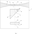
- Figure 1 shows a plan view of a cartridge 1 according to an embodiment of the present invention.
- the cartridge 1 comprises, a channel 1a along which a sample fluid can flow; the channel has a length 'L' and it extends along an axis 2a, referred to hereafter as the channel axis 2a.
- the channel axis 2a extends along the middle of the channel 1a.
- the channel 1a has a start 1b and an end 1c; typically, when in use a sample will be made flow in a direction from the start 1b of the channel 1a, along the length L of the channel 1a, to the end 1c of the channel 1a.
- the cartridge 1 further comprises one or more elements 3,4 which are configured to manipulate light in a predefined manner, and wherein said one or more elements 3,4 are located in a predefined position relative to the channel 1a.
- the cartridge 1 comprises a first element 3 and a second element 4.
- the first element 3 is located at a predefined distance, along a second axis 2b which is perpendicular to the channel axis 2a, from the channel 1a.
- the intersection of the channel axis 2a and the second axis 2b defines the centre 2c of the channel 1a.
- the first element 3 is substantially cuboid shaped; specifically in this example the first element 3 is defined by a cuboid-shaped cavity 3.
- the first element 3 has a substantially rectangular-shaped surface 3c (which is the floor of the cuboid-shaped cavity 3) and this substantially rectangular-shaped surface 3c is configured to reflect light. It should be noted that the first element 3 may have any suitable shape; for example the first element 3 may have any arbitrary shape which has a portion (or a side 3a,3b), which is positioned opposite to the channel 1a and which is orientated parallel to the channel 1a.
- the second element 4 is located at a predefined position along an axis which is parallel to the channel axis; in other words the second element 4 is located opposite to a predefined section of the channel axis 2a.
- the second element 4 is located opposite to the channel 1a.
- the second element 4 is substantially triangular-prism-shaped; specifically in this example the second element 4 is defined by a triangular-prism-shaped cavity 4.
- the second element 4 has a substantially triangular-shaped surface 4a (which is the floor of the triangular-prism-shaped cavity 4) and this substantially triangular-shaped surface 4a is configured to reflect light.
- the second element 4 is located opposite to the channel 1a.
- the second element 4 is orientated so that a first side 4b of the triangular-prism-shaped second element 4 is parallel to the channel axis 2a.
- a second side 4c of the of the triangular-prism-shaped second element 4 forms a predefined angle "x" with the first side 4b.
- the distance, along an axis parallel to the second axis 2b, between the first side 4b and the second side 4c is known.
- the distance, along an axis parallel to the second axis 2b, between the first side 4b and the second side 4c is known.
- the cartridge 1 of the present invention is not limited to requiring both a first and second element 3,4; on the contrary in another embodiment the cartridge 1 may comprise only the first element 3 (i.e. no second element 4).
- first and second elements 3,4 may take any suitable shape; the present invention is not limited to requiring that the first element be cuboid-shaped and that the second element be triangular-prism-shaped.
- the surface 4a of the triangular-prism-shaped second element 4 could be an equilateral triangular shape; an isosceles-triangular shape; or a right-angled triangular shape.
- said elements may be configured to manipulate light in any suitable manner, for example the elements could be configured to absorb light, reflect light, and/or scatter light; also in yet a further embodiment one or more of said elements may be configured to be auto-fluorescent.
- Figure 2 shows a side view of side view of an assembly 100 according to an embodiment of the present invention, which uses the cartridge 1 of Figure 1 .
- the assembly 100 comprises the cartridge 1 as shown in Figure 1 , and an optical device 5 which is configured such that it can be selectively operated to emit a light (in the form of a light beam).
- the optical device 5 is arranged such that the emitted light beam will be incident on the cartridge 1.
- the optical device 5 is arranged to emit light via a lens 6 which is provided in the optical device 5.
- the assembly 100 further comprises a means for moving the optical device with respect to the cartridge, or a means for moving said cartridge with respect to the optical device.
- the assembly 100 comprises a means for moving the optical device with respect to the cartridge, in the form of a carriage 9.
- the optical device 5 is mounted on the carriage 9, and the carriage can move so as to move the optical device with respect to the cartridge 1.
- the assembly 100 further comprises a sensor 12 which can receive light from said cartridge 1 (said light having been originally emitted by said optical device 5 and having being reflected by the cartridge back to the sensor 12).
- the sensor 12 can output a signal which is representative of the light which it receives.
- the sensor 12 is in the form of a photodiode 12; however it should be understood that the sensor 12 may take any suitable form.
- the assembly 100 of Figure 2 can be used to perform a method of arranging the optical device into a predefined position with respect to the cartridge, according to a further aspect of the present invention.
- the method comprises the steps of,
- the method comprises determining how to move the optical device so that it is aligned above any point which is on the channel axis 2a, between the start 1b and the end 1c of the channel; and then moving the optical device 5 so that it is aligned above any point which is on the channel axis 2a, between the start 1b and the end 1c of the channel.
- the cartridge 1 needs only comprise the first element 3 (i.e.
- the second element 4 is not necessary; thus the second element 4 is not an essential element of the cartridge 1 because alignment of the optical device above any point which is on the channel axis 2a, between the start 1b and the end 1c of the channel, will allow for the laser beam emitted by the optical device with the channel 1a to be incident on any sample under test, which flows in the channel).
- the method comprises determining how to move the optical device so that it is aligned above a point which is on the channel axis 2a, and is equal distance between the start 1b and the end 1c of the channel (in this case the centre of the channel 1a is the point 2c at which the channel axis 2a and the second axis 2b intersect); and then moving the optical device 5 so that it is aligned above said point which on the channel axis 2a, and is equal distance between the start 1b and the end 1c of the channel.
- the cartridge 1 must have at least the first and second elements 3,4.
- the optical device 5 will be moved using the carriage 9.
- the carriage 9 will have a stepper motor, so the optical device 5 will be moved, step-wise, from the starting position, over the cartridge 1 and over said first and second elements 3,4 on the cartridge.
- the movement of the optical device 5, from the starting position, over the cartridge 1 and over said first and second elements 3,4 on the cartridge, may be stopped at any point after the optical device has passed over the first and second elements 3,4.
- the starting position will be a predefined location on the cartridge 1, wherein the first and second elements 3,4 will be located between the starting position and the channel 1a; so when the optical device 5 is moved, it will be moved, from the starting position in the direction of the channel 1a so that it passes over the first and second elements 3,4 which are located between the starting position and the channel 1a. It should be noted that the optical device 5 is most preferably moved linearly from the starting position, over the first and second elements 3,4, in the direction of the channel 1a.
- the optical device 5 may be further moved to also pass over the channel 1a.
- the channel 1a will typically manipulate light which it receives from the optical device, so that output signal which represents light detected by the sensor at each position of the optical device 5 will also indicate at what position the optical device was aligned over the channel 1a.
- the channel 1a typically has such small dimensions, it is easy to mistake the change in the output signal of the sensor when the optical device 5 is aligned over the channel 1a, for noise.
- the cartridge 1 of the present invention is not limited to requiring both a first and second element 3,4; on the contrary in another embodiment the cartridge 1 may comprise only the first element 3 (i.e. no second element 4); in this case alignment of the optical device 5 over above a point (any point) which is on the channel axis 2a, between the start 1b and the end 1c of the channel 1a, can be achieved (i.e. the optical device will be positioned somewhere along the channel axis 2a; but may not necessarily be aligned the point 2c which is equal distance between the start 1b and the end 1c of the channel 1a).
- the optical device 5 can be successfully positioned above a point (any point) which is on the channel axis 2a, somewhere between the start 1b and the end 1c of the channel 1a.
- the cartridge is only required to have a second element 4 in order to be able to consistently align the optical device 5 over said point 2c which on the channel axis 2a, and is equal distance between the start 1b and the end 1c of the channel.
- Figure 3 provides an example of an output signal which is provided by the sensor 12 when the optical device 5 has been moved from the starting position, over the cartridge 1 and over said first and second elements 3,4 on the cartridge 1.
- the output signal represents light detected by the sensor 12 (e.g. the output signal represents the intensity of light received by the sensor 12) at each position of the optical device 5.
- recorded position of the optical device 5 is shown on the x-axis; and at each position for the optical device 5, the output signal represents light detected by the sensor 12 (e.g. the output signal represents the intensity of light received by the sensor 12) when the optical device 5 was located at that position.
- the first and second elements 3,4 are configured to manipulate light by reflection of light, it can be expected that when the output signal will show some changes when the optical device 5 was positioned over these elements 3,4, compared to the output signal when the optical device 5 was position over other parts of the cartridge 1 (it should be noted that the other parts of the cartridge 1 are not configured to manipulate light in the same manner as the first and second elements 3,4).
- the first and second elements 3,4 are configured to reflect light, when the optical device is positioned over the first and/or second elements 3,4 it can be expected that the level of light (e.g. the intensity of light) which the sensor 12 receives will increase (or for an element 3,4 which is designed to absorb light, it can be expected that the level of light (e.g.
- the position(s) along the x-axis, at which output signal show increased levels of light (e.g. increase in the intensity of light) received by the sensor 12, correspond to the position(s) at which the optical device 5 was aligned over the first and second 3,4 elements. Since the starting position is known, and the direction which the optical device was moved across the cartridge towards the cartridge is known (i.e. linear direction; the optical device is preferably moved linearly from the starting position, over the first and second elements 3,4, in the direction of the channel 1), it can be determined which of the elements 3,4, the optical device passed over the first.
- the optical device 5 was moved from the starting position, in a direction towards of the channel 1a, over the first element 3 first, and then over the second element 4.
- the first increase in the output signal which occurs between 1250 ⁇ m-1400 ⁇ m corresponds to when the optical device 5 was aligned over the first element 3
- the next increase in the output signal which occurs between 1950 ⁇ m-2750 ⁇ m corresponds to when the optical device 5 was aligned over the second element 4.
- the first element 3 is at a predefined distance from the channel 1a, and the position (i.e. between 1250mm-1400mm from the starting position) at which the optical device 5 is aligned over the first element 3 can be determined from the output signal, these aspects can be used to determine how to move the optical device 5 so that it is aligned above a point (any point) which is on the channel axis 2a, and which is between the start 1b and the end 1c of the channel 1a.
- the optical device 5 is moved back to an interim position, wherein the interim position is any position which is before the said determined position.
- the interim position is the starting position; however the interim position could be any other position which is located before the said determined position (in the direction of movement from the stating position to the determined position); for example the interim position could alternatively be a position which is between the starting position and the determined position.
- the interim position is a position which lies on an axis which intersects both the starting position and said determined position. Then the optical device is moved from the interim position (preferably starting position) to the position corresponding to said determined position (i.e.
- said optical device 5 is moved from said determined position, a distance corresponding to the predefined distance which the first element 3 is from the channel 1a, so that the optical device is aligned above a point (any point) which is on the channel axis 2a, and which is between the start 1b and the end 1c of the channel 1a.
- the optical device 5 is moved from its current position to the position corresponding to said determined position (i.e. the position determined from the output signal, at which the optical device 5 was aligned over the first element 3; which in this example shown in Figure 3 , is, either, 1250 ⁇ m from the starting position (if the predefined position of the first element 3 relative to the channel 1a, is measured from a first side 3a of the first element (the first side 3a being a side of the first element 3 over which the optical device first passes)); or, 1400 ⁇ m from the starting position (if the predefined position of the first element 3 relative to the channel 1a, is measured from a second side 3b of the first element 3 (the second side 3b being a side of the first element immediately before it has completed passing over the first element 3)); then said optical device 5 is moved from said determined position, a distance corresponding to the predefined distance which the first element 3 is from the channel 1a, so that the optical device is aligned above a point (any point) which is
- the distance from the current position which the optical device 5 occupies, to the said determined position i.e. the position determined from the output signal, at which the optical device 5 was aligned over the first element 3; which in this example shown in Figure 3 , is, either, 1250 ⁇ m from the starting position (if the predefined position of the first element 3 relative to the channel 1a, is measured from a first side 3a of the first element (the first side 3a being a side of the first element 3 over which the optical device first passes)); or, 1400 ⁇ m from the starting position (if the predefined position of the first element 3 relative to the channel 1a, is measured from a second side 3b of the first element 3 (the second side 3b being a side of the first element immediately before it has completed passing over the first element 3)), is determined.
- the said determined distance is subtracted from the predefined distance which the first element 3 is from the channel 1a, to provide a distance value; and then said optical device 5 is moved from said current position, a distance corresponding to the distance value, so that the optical device is aligned above a point (any point) which is on the channel axis 2a, and which is between the start 1b and the end 1c of the channel 1a.
- first, second and third embodiments the cartridge 1 is not required to have a second element 4 in order to align the optical device 5 above a point (any point) which is on the channel axis 2a, and which is between the start 1b and the end 1c of the channel 1a; only the first element 3 is necessary to implement these embodiments.
- further additional steps may be carried out, which require that the cartridge 1 have the second element 4, in order to further align the optical device 5 above a point 2c which is equal distance between the start 1b and the end 1c of the channel 1a.
- the optical device 5 can be aligned above a point 2c which is on the channel axis 2a, and is equal distance between the start 1b and the end 1c of the channel 1a.
- determining how to move the optical device 5 so that it is aligned above a point 2c which is equal distance between the start 1b and the end 1c of the channel 1a can be carried out a plurality of different ways, as will be described in more detail below.
- this can be used to determine how to move the optical device 5 along the channel axis 2a so that it is aligned above a point 2c which is equal distance between the start 1b and the end 1c of the channel 1a.
- the first element 3 is used to determine how to move the optical device 5 so that it is on the channel axis 2a
- the second element 4 is used to determine how to move the optical device along the channel axis 2a so that the optical device 5 is aligned above a point 2c, which is equal distance between the start 1b and the end 1c of the channel 1a.
- the part of the output signal which corresponds to when the optical device 5 was aligned over the second element 4 is used to determine the length of the triangular-shaped surface 4a of the second element 4 over which the optical device 5 passed; in this example at position 1950 ⁇ m the optical device 5 began to pass over the second element (i.e. the optical device 5 was aligned above the second side 4c of the second element 4); at position 2750 ⁇ m the optical device 5 was aligned above the first side 4b of the second element 4 (i.e. immediately before the optical device 5 had passed over the second element completely); therefore the length of the triangular-shaped surface 4a of second element 5 over which the optical device 5 passed was '800 ⁇ m' (i.e. 2750 ⁇ m-1950 ⁇ m).
- the first side 4b of the triangular-prism-shaped second element 4 is parallel to the channel axis 2a; and the second side 4c of the of the triangular-prism-shaped second element 4 forms a predefined angle "x" with the first side 4b; and since directly opposite to the start 1b of the channel 1a, the distance, along an axis parallel to the second axis 2b, between the first side 4b and the second side 4c, is known; and, directly opposite to the end 1c of the channel 1a, the distance, along an axis parallel to the second axis 2b, between the first side 4b and the second side 4c, is known; and given that the optical device was moved linearly from the starting position towards the channel; using the length of the triangular-shaped surface 4a of second element 4 over which the optical device passed (i.e.800 ⁇ m - which has been determined from the output signal) it can be determined how to move the optical device 5, along the channel axis 2a, in order to align the optical device 5 above the
- a predefined scaling factor is provided, wherein the scaling factor is a multiple which will convert the width of the portion of the output signal which corresponds to when the optical device was passing over the second element 4, to the physical length of the triangular-shaped surface 4a of second element 4.
- the scaling factor is a multiple which will convert the width of the portion of the output signal which corresponds to when the optical device was passing over the second element 4, to the physical length of the triangular-shaped surface 4a of second element 4.
- the first side 4b of the triangular-prism-shaped second element 4 is parallel to the channel axis 2a; and the second side 4c of the of the triangular-prism-shaped second element 4 forms a predefined angle "x" with the first side 4b; and since directly opposite to the start 1b of the channel 1a, the distance, along an axis parallel to the second axis 2b, between the first side 4b and the second side 4c, is known; and, directly opposite to the end 1c of the channel 1a, the distance, along an axis parallel to the second axis 2b, between the first side 4b and the second side 4c, is known; and given that the optical device was moved linearly from the starting position towards the channel; using the length of the triangular-shaped surface 4a of second element 4 over which the optical device passed (which has been determined by multiplying the measured width by the predefined scaling factor) it can be determined how to move the optical device 5, along the channel axis 2a, in order to align the optical device 5 above the point
- the scaling factor is determined in a calibration step, whereby the optical device 5 is passed over various, known, lengths of the triangular-shaped surface 4a, to obtain various output signals which have corresponding output signals with various widths; the mathematical relationship between the widths of the signal and the physical length of the triangular-shaped surface 4a can be determined. The inverse of this mathematical relationship can then be defined using the scaling factor, which can be multiplied by the width of an output signal obtained when the optical device 5 passes over the triangular-shaped surface 4a of second element 4, to provide the physical length of the triangular-shaped surface 4a.
- the method comprises determining the scaling factor based on the part of the output signal which is output from the sensor when the optical device 5 was over the first element 3.
- the length of the surface 3c over which the optical device passes is predefined (e.g. the distance between the first side 3a and second side 3b of the first element 3 is predefined (assuming the optical device will be moved over the surface 3c of the first element in a direction which is perpendicular to the channel axis 2a); in other words the distance between the first side 3a and second side 3b of the first element 3 is a priori known).
- the scaling factor may then be determined by measuring a width of the first part of the output signal which is output from the optical device when the optical device is positioned over the first element; so in the example shown in Figure 3 this would be done by measuring the width of the output signal which is between positions 1250 ⁇ m on the x-axis and the 1400 ⁇ m on the x-axis. And then dividing said predefined length of the surface 3c over which the optical device passes by the measured width (i.e. dividing the distance between the first side 3a and second side 3b of the first element 3, by the measured width to provide the scaling factor).
- the scaling factor is simply a multiple by which the width of parts of the output signal corresponding to when the optical device was positioned over the element, of can be multiplied so as to obtain physical dimension of the element.
- This scaling factor can then be used to determine, from the width of the optical signal which is output by the sensor when the optical device 5 is positioned over the second element 4, the length of the surface 4a of the second element 4 over which the optical device 5 passed; so in the example shown in Figure 3 this would be done by measuring the width of the output signal which is between positions 1950 ⁇ m on the x-axis and the 2750 ⁇ m on the x-axis, and then multiplying that width by the aforementioned scaling factor (which was determined from the first element 3) to provide the length of the surface 4a of the second element 4 over which the optical device 5 passed.
- a predefined part of the second element 4 is aligned with the start 1b of the channel, and wherein said predefined part of the second element has a predefined length of surface 4a between the first and second sides 4b,4c (This can be done, for example, by simply in a calibration step which comprise measuring the length of surface 4a between the first and second sides 4b,4c of the second element 4 at a position which is directly opposite the start 1b of the channel 1).
- the channel 1a has a predefined length 'L' (the predefined length 'L' of the channel may be determined in a calibration step for example, wherein the length of the channel 1a between the start 1b and end 1c is measured).
- the distance between the part of the triangular-shaped surface 4a over which the optical device 5 passed, and the predefined part of the second element 4 which is aligned with the start 1b of the channel 1a is determined; and based on said determined distance and the predefined length 'L' of the channel, determine how to move the optical device 5 along the channel axis 2a so that it is aligned above the point 2c which is equal distance between the start 1b and the end 1c of the channel 1a.
- first and second elements 3,4 are a predefined distance apart on the cartridge 1; this predefined distance is used to identify which increase in the output signal is caused by the first element 3 and which increase in the output signal is caused by the second element 4.
- this embodiment further comprises, identifying sections of the output signal which contain signals which are representative of manipulation of light, which are a distance (along the x-axis) apart which corresponds to the distance between the first and second elements on the cartridge.
- the output signal in Figure 3 it is known that the distance between the second side 3b of the first element 3 and the first side 4b of the second element 4 on the cartridge is 1350 ⁇ m; accordingly, referring to Figure 3 , it can be determined that the increase in the output signal which trails the position 2750 ⁇ m (on the x-axis) is due to the second element 4; and any increase in the output signal which occurs between position 1400 ⁇ m (on the x-axis) and the increase in the output signal which trails the position 2750 ⁇ m (on the x-axis) is noise.
- knowing the distance between the first and second elements 3,4 on the cartridge 1, facilitates a user enables a user to more reliably identify increases in the output signal due to the first and second elements 3,4; and thus also allows to more reliably identify increases in the output signal due to noise.
- the length of the surface of over which the optical device moves is the distance over said surface over which the optical device moves.
- the length of the surface 3c (rectangular-shaped surface 3c) of the first element 3 over which the optical device moves is the distance over said surface 3c (rectangular-shaped surface 3c) over which the optical device moves;
- the length of the surface 4a (triangular-shaped surface 4a) over which the optical device moves is the distance over said surface 4a (triangular-shaped surface 4a) over which the optical device moves.
- the method of present invention may further comprise the step of processing the output signal.
- the processed output signal (not the original output signal) is then used when performing the above-mentioned methods of the present invention.
- Processing the output signal may comprise one or more steps:
- processing the output signal may comprise, linearizing the output signal; and/or filtering the output signal.
- step of filtering said output signal may comprise smoothing said linearized signal using a finite impulse response filter.
- processing the output signal may comprise, adding data points to said output signal at points corresponding to positions where the sensor 12 failed to record the light which it received from said cartridge 1 and/or elements 3,4.
- said value of each data point is determined by interpolation of two data points on either side of said respective point corresponding to the respective position where the sensor failed to record the light which it received from said cartridge 1 and/or elements 3,4.
- processing the output signal may comprise, defining a gauge which represents an ideal shape of the output signal which is output from said sensor 12 when the optical device 5 passes over an element 3,4; and then identifying the portion of the output signal which best fits to that gauge as corresponding to when the optical device 5 was positioned over the corresponding element 3,4.
- processing the output signal comprises, defining a gauge for each respective element on the cartridge, which represents an ideal shape of the output signal which is output from said sensor 12 when the optical device 5 passes over that element; and then, for each gauge, identifying the portion of the output signal which best fits to that gauge as corresponding to when the optical device 5 was positioned over the corresponding element 3,4.
- the step of identifying the portion of the output signal which best fits to that gauge may comprise comparing the gauge with successive portions of the output signal, and identifying the portion of the output signal which best fits the gauge.
- the comparison between the gauge and the successive portions of the output signal may be carried out using auto-correlation or convolution.
Description
- The present invention concerns a cartridge which has a channel and one or more elements which are configured to manipulate light in a predefined manner, which are located in a predefined position relative to the channel. There is further provided an assembly which comprises a cartridge and an optical device; and a method of arranging the optical device with respect to the cartridge so that the optical device is aligned over the channel.
- Flow cytometers usually comprise an interrogation area which is typically a channel along which a sample will flow; and a laser which can emit a laser beam which is made incident on the sample flowing in the channel so that the sample can be analyzed. A critical requirement in flow cytometry is that the laser beam must be in alignment with the interrogation area (i.e. the laser beam must be incident on the interrogation area) otherwise the laser beam will fail to be incident on the sample in the interrogation area. Without proper alignment of the laser with the interrogation area, a sample passing through the interrogation area will not be properly illuminated by the laser beam emitted by the laser, resulting in a very weak optical response signal or worse still, no optical response signal at all; this ultimately results in failure to analyze the sample.
- Typical dimensions of the interrogation area and spot size of the laser beam are between 10 and 100 micrometers; the small dimensions of the laser beam spot size and the interrogation area makes alignment of the laser beam with the interrogation area even more difficult. This necessitates the need for a method to accurately align the laser beam with the interrogation area.
- When the interrogation area is provided in a replaceable cartridge this means that every time a new cartridge is provided in a flow cytometer, the laser beam must be aligned with the interrogation area; in other words the laser must be moved so that the laser beam which it emits is incident on the interrogation area (typically a channel) of the new cartridge. This necessitates the need for a quick, uncomplicated method for aligning the laser beam with the interrogation area.
-
US2005134850 discloses an optical alignment system for aligning a light beam with a core flow in a flow stream. The flow stream may have a sheath fluid and a core flow, where the core flow has a current position within the flow stream. A light source may be used to produce a light beam, and an optical element may be used to direct the light beam at the core flow. In some embodiments, an actuator is provided for moving the optical element, light source and/or flow stream such that the light directed by the optical element is aligned with the current position of the core flow. - Disadvantageously, existing methods for aligning the laser beam with the interrogation area, are complicated, and/or slow, and/or often fail to achieve accurate alignment. Furthermore, it follows that existing cartridges, and assemblies, are not designed to facilitate uncomplicated, and/or fast, and/or accurate alignment.
- It is an aim of the present invention to mitigate at least some of the disadvantages associated with existing methods, cartridges, and assemblies.
- According to the invention, the aim of the present invention are achieved by the method having the features recited in the independent claim, wherein the dependent claims recite optional features of preferred embodiments.
- The invention will be better understood with the aid of the description of an embodiment given by way of example and illustrated by the figures, in which:
-
Fig. 1 shows a plan view of a cartridge according to an embodiment of the present invention; -
Fig. 2 shows a side view of an assembly according to an embodiment of the present invention; -
Fig. 3 is an example of an output signal provided by the sensor in the assembly ofFig. 2 when the optical device is passed over the first and second elements of the cartridge. -
Figure 1 shows a plan view of acartridge 1 according to an embodiment of the present invention. Thecartridge 1 comprises, achannel 1a along which a sample fluid can flow; the channel has a length 'L' and it extends along anaxis 2a, referred to hereafter as thechannel axis 2a. Thechannel axis 2a extends along the middle of thechannel 1a. Thechannel 1a has astart 1b and anend 1c; typically, when in use a sample will be made flow in a direction from thestart 1b of thechannel 1a, along the length L of thechannel 1a, to theend 1c of thechannel 1a. - The
cartridge 1 further comprises one ormore elements more elements channel 1a. In this example thecartridge 1 comprises afirst element 3 and asecond element 4. Thefirst element 3 is located at a predefined distance, along asecond axis 2b which is perpendicular to thechannel axis 2a, from thechannel 1a. The intersection of thechannel axis 2a and thesecond axis 2b, defines thecentre 2c of thechannel 1a. In this example thefirst element 3 is substantially cuboid shaped; specifically in this example thefirst element 3 is defined by a cuboid-shaped cavity 3. Thus, thefirst element 3 has a substantially rectangular-shaped surface 3c (which is the floor of the cuboid-shaped cavity 3) and this substantially rectangular-shaped surface 3c is configured to reflect light. It should be noted that thefirst element 3 may have any suitable shape; for example thefirst element 3 may have any arbitrary shape which has a portion (or aside channel 1a and which is orientated parallel to thechannel 1a. - The
second element 4 is located at a predefined position along an axis which is parallel to the channel axis; in other words thesecond element 4 is located opposite to a predefined section of thechannel axis 2a. In this example it can be seen fromFigure 1 that thesecond element 4 is located opposite to thechannel 1a. In this example thesecond element 4 is substantially triangular-prism-shaped; specifically in this example thesecond element 4 is defined by a triangular-prism-shaped cavity 4. Thus thesecond element 4 has a substantially triangular-shaped surface 4a (which is the floor of the triangular-prism-shaped cavity 4) and this substantially triangular-shaped surface 4a is configured to reflect light. - As motioned the
second element 4 is located opposite to thechannel 1a. Thesecond element 4 is orientated so that afirst side 4b of the triangular-prism-shapedsecond element 4 is parallel to thechannel axis 2a. Asecond side 4c of the of the triangular-prism-shapedsecond element 4 forms a predefined angle "x" with thefirst side 4b. Directly opposite to thestart 1b of thechannel 1a, the distance, along an axis parallel to thesecond axis 2b, between thefirst side 4b and thesecond side 4c, is known. Likewise, directly opposite to theend 1c of thechannel 1a, the distance, along an axis parallel to thesecond axis 2b, between thefirst side 4b and thesecond side 4c, is known. - It should be understood that the
cartridge 1 of the present invention is not limited to requiring both a first andsecond element cartridge 1 may comprise only the first element 3 (i.e. no second element 4). - It should be understood that the first and
second elements surface 4a of the triangular-prism-shapedsecond element 4 could be an equilateral triangular shape; an isosceles-triangular shape; or a right-angled triangular shape. - It should also be understood that said elements may be configured to manipulate light in any suitable manner, for example the elements could be configured to absorb light, reflect light, and/or scatter light; also in yet a further embodiment one or more of said elements may be configured to be auto-fluorescent.
-
Figure 2 shows a side view of side view of anassembly 100 according to an embodiment of the present invention, which uses thecartridge 1 ofFigure 1 . - The
assembly 100 comprises thecartridge 1 as shown inFigure 1 , and anoptical device 5 which is configured such that it can be selectively operated to emit a light (in the form of a light beam). Theoptical device 5 is arranged such that the emitted light beam will be incident on thecartridge 1. In this example theoptical device 5 is arranged to emit light via alens 6 which is provided in theoptical device 5. - The
assembly 100 further comprises a means for moving the optical device with respect to the cartridge, or a means for moving said cartridge with respect to the optical device. In this example theassembly 100 comprises a means for moving the optical device with respect to the cartridge, in the form of acarriage 9. Theoptical device 5 is mounted on thecarriage 9, and the carriage can move so as to move the optical device with respect to thecartridge 1. - The
assembly 100 further comprises asensor 12 which can receive light from said cartridge 1 (said light having been originally emitted by saidoptical device 5 and having being reflected by the cartridge back to the sensor 12). Thesensor 12 can output a signal which is representative of the light which it receives. In this example thesensor 12 is in the form of aphotodiode 12; however it should be understood that thesensor 12 may take any suitable form. - The
assembly 100 ofFigure 2 can be used to perform a method of arranging the optical device into a predefined position with respect to the cartridge, according to a further aspect of the present invention. - The method comprises the steps of,
- operating the
optical device 5 to emit light which is incident on thecartridge 1; - moving the
optical device 5, from a starting position, over thecartridge 1 and over said first andsecond elements second elements - as the
optical device 5 is moved from said starting position, over thecartridge 1 and over said first andsecond elements optical device 5 relative to the starting position; - at each position for the optical device, detecting light using said
sensor 12 and outputting from the sensor 12 a signal which represents light detected by thesensor 12, so as to provide an output signal which represents light detected by the sensor at each position of theoptical device 5, and then - determining, from said output signal, the respective positions at which the
optical device 5 was aligned over said first andsecond elements - then determining how to move the optical device so that it is aligned above the
channel 1a using said determined positions and the predefined position of said first andsecond elements channel 1a; and then moving the optical device so that it is aligned above thechannel 1a. - With regards to the step of then determining how to move the optical device so that it is aligned above the
channel 1a, it should be understood that in some embodiments the method comprises determining how to move the optical device so that it is aligned above any point which is on thechannel axis 2a, between thestart 1b and theend 1c of the channel; and then moving theoptical device 5 so that it is aligned above any point which is on thechannel axis 2a, between thestart 1b and theend 1c of the channel. For such embodiments thecartridge 1 needs only comprise the first element 3 (i.e. thesecond element 4 is not necessary; thus thesecond element 4 is not an essential element of thecartridge 1 because alignment of the optical device above any point which is on thechannel axis 2a, between thestart 1b and theend 1c of the channel, will allow for the laser beam emitted by the optical device with thechannel 1a to be incident on any sample under test, which flows in the channel). - In other embodiments the method comprises determining how to move the optical device so that it is aligned above a point which is on the
channel axis 2a, and is equal distance between thestart 1b and theend 1c of the channel (in this case the centre of thechannel 1a is thepoint 2c at which thechannel axis 2a and thesecond axis 2b intersect); and then moving theoptical device 5 so that it is aligned above said point which on thechannel axis 2a, and is equal distance between thestart 1b and theend 1c of the channel. For such embodiments thecartridge 1 must have at least the first andsecond elements - In this example the
optical device 5 will be moved using thecarriage 9. Typically thecarriage 9 will have a stepper motor, so theoptical device 5 will be moved, step-wise, from the starting position, over thecartridge 1 and over said first andsecond elements optical device 5, from the starting position, over thecartridge 1 and over said first andsecond elements second elements cartridge 1, wherein the first andsecond elements channel 1a; so when theoptical device 5 is moved, it will be moved, from the starting position in the direction of thechannel 1a so that it passes over the first andsecond elements channel 1a. It should be noted that theoptical device 5 is most preferably moved linearly from the starting position, over the first andsecond elements channel 1a. - In one example the
optical device 5 may be further moved to also pass over thechannel 1a. In this case thechannel 1a will typically manipulate light which it receives from the optical device, so that output signal which represents light detected by the sensor at each position of theoptical device 5 will also indicate at what position the optical device was aligned over thechannel 1a. However, since thechannel 1a typically has such small dimensions, it is easy to mistake the change in the output signal of the sensor when theoptical device 5 is aligned over thechannel 1a, for noise. - As mentioned the
cartridge 1 of the present invention is not limited to requiring both a first andsecond element cartridge 1 may comprise only the first element 3 (i.e. no second element 4); in this case alignment of theoptical device 5 over above a point (any point) which is on thechannel axis 2a, between thestart 1b and theend 1c of thechannel 1a, can be achieved (i.e. the optical device will be positioned somewhere along thechannel axis 2a; but may not necessarily be aligned thepoint 2c which is equal distance between thestart 1b and theend 1c of thechannel 1a). Provided that thefirst element 3 extends along an axis which is parallel to thechannel axis 2a, and provided the length which thefirst element 3 extends along said axis is not greater than the length 'L' which thechannel 1a extends long thechannel axis 2a, then, using the present invention, theoptical device 5 can be successfully positioned above a point (any point) which is on thechannel axis 2a, somewhere between thestart 1b and theend 1c of thechannel 1a. The cartridge is only required to have asecond element 4 in order to be able to consistently align theoptical device 5 over saidpoint 2c which on thechannel axis 2a, and is equal distance between thestart 1b and theend 1c of the channel. -
Figure 3 provides an example of an output signal which is provided by thesensor 12 when theoptical device 5 has been moved from the starting position, over thecartridge 1 and over said first andsecond elements cartridge 1. The output signal represents light detected by the sensor 12 (e.g. the output signal represents the intensity of light received by the sensor 12) at each position of theoptical device 5. As shown inFigure 3 recorded position of theoptical device 5 is shown on the x-axis; and at each position for theoptical device 5, the output signal represents light detected by the sensor 12 (e.g. the output signal represents the intensity of light received by the sensor 12) when theoptical device 5 was located at that position. - Since the first and
second elements optical device 5 was positioned over theseelements optical device 5 was position over other parts of the cartridge 1 (it should be noted that the other parts of thecartridge 1 are not configured to manipulate light in the same manner as the first andsecond elements 3,4). In this example the first andsecond elements second elements sensor 12 receives will increase (or for anelement sensor 12 receives will decrease). Thus, the position(s) along the x-axis, at which output signal show increased levels of light (e.g. increase in the intensity of light) received by thesensor 12, correspond to the position(s) at which theoptical device 5 was aligned over the first and second 3,4 elements. Since the starting position is known, and the direction which the optical device was moved across the cartridge towards the cartridge is known (i.e. linear direction; the optical device is preferably moved linearly from the starting position, over the first andsecond elements elements optical device 5 was moved from the starting position, in a direction towards of thechannel 1a, over thefirst element 3 first, and then over thesecond element 4. Thus, as can be seen in the output signal ofFigure 3 , the first increase in the output signal which occurs between 1250µm-1400µm (i.e. between 1250µm-1400µm from the starting position), corresponds to when theoptical device 5 was aligned over thefirst element 3; and the next increase in the output signal which occurs between 1950µm-2750µm (i.e. between 1950µm-2750µm from the starting position) corresponds to when theoptical device 5 was aligned over thesecond element 4. - Since the
first element 3 is at a predefined distance from thechannel 1a, and the position (i.e. between 1250mm-1400mm from the starting position) at which theoptical device 5 is aligned over thefirst element 3 can be determined from the output signal, these aspects can be used to determine how to move theoptical device 5 so that it is aligned above a point (any point) which is on thechannel axis 2a, and which is between thestart 1b and theend 1c of thechannel 1a. - For example, in a first embodiment the
optical device 5 is moved back to an interim position, wherein the interim position is any position which is before the said determined position. Most preferably the interim position is the starting position; however the interim position could be any other position which is located before the said determined position (in the direction of movement from the stating position to the determined position); for example the interim position could alternatively be a position which is between the starting position and the determined position. Most preferably the interim position is a position which lies on an axis which intersects both the starting position and said determined position. Then the optical device is moved from the interim position (preferably starting position) to the position corresponding to said determined position (i.e. the position determined from the output signal, at which theoptical device 5 was aligned over thefirst element 3; which in this example shown inFigure 3 , is, either, 1250µm from the starting position (if the predefined position of thefirst element 3 relative to thechannel 1a, is measured from afirst side 3a of the first element (thefirst side 3a being a side of thefirst element 3 over which the optical device first passes)); or, 1400µm from the starting position (if the predefined position of thefirst element 3 relative to thechannel 1a, is measured from asecond side 3b of the first element 3 (thesecond side 3b being a side of the first element immediately before it has completed passing over the first element 3)). Then saidoptical device 5 is moved from said determined position, a distance corresponding to the predefined distance which thefirst element 3 is from thechannel 1a, so that the optical device is aligned above a point (any point) which is on thechannel axis 2a, and which is between thestart 1b and theend 1c of thechannel 1a. - In a second embodiment, for example the
optical device 5 is moved from its current position to the position corresponding to said determined position (i.e. the position determined from the output signal, at which theoptical device 5 was aligned over thefirst element 3; which in this example shown inFigure 3 , is, either, 1250µm from the starting position (if the predefined position of thefirst element 3 relative to thechannel 1a, is measured from afirst side 3a of the first element (thefirst side 3a being a side of thefirst element 3 over which the optical device first passes)); or, 1400µm from the starting position (if the predefined position of thefirst element 3 relative to thechannel 1a, is measured from asecond side 3b of the first element 3 (thesecond side 3b being a side of the first element immediately before it has completed passing over the first element 3)); then saidoptical device 5 is moved from said determined position, a distance corresponding to the predefined distance which thefirst element 3 is from thechannel 1a, so that the optical device is aligned above a point (any point) which is on thechannel axis 2a, and which is between thestart 1b and theend 1c of thechannel 1a. - In a third embodiment the distance from the current position which the
optical device 5 occupies, to the said determined position (i.e. the position determined from the output signal, at which theoptical device 5 was aligned over thefirst element 3; which in this example shown inFigure 3 , is, either, 1250µm from the starting position (if the predefined position of thefirst element 3 relative to thechannel 1a, is measured from afirst side 3a of the first element (thefirst side 3a being a side of thefirst element 3 over which the optical device first passes)); or, 1400µm from the starting position (if the predefined position of thefirst element 3 relative to thechannel 1a, is measured from asecond side 3b of the first element 3 (thesecond side 3b being a side of the first element immediately before it has completed passing over the first element 3)), is determined. Then the said determined distance is subtracted from the predefined distance which thefirst element 3 is from thechannel 1a, to provide a distance value; and then saidoptical device 5 is moved from said current position, a distance corresponding to the distance value, so that the optical device is aligned above a point (any point) which is on thechannel axis 2a, and which is between thestart 1b and theend 1c of thechannel 1a. - It should be noted that in the afore mentioned, first, second and third embodiments the
cartridge 1 is not required to have asecond element 4 in order to align theoptical device 5 above a point (any point) which is on thechannel axis 2a, and which is between thestart 1b and theend 1c of thechannel 1a; only thefirst element 3 is necessary to implement these embodiments. As will be subsequently described, further additional steps may be carried out, which require that thecartridge 1 have thesecond element 4, in order to further align theoptical device 5 above apoint 2c which is equal distance between thestart 1b and theend 1c of thechannel 1a. Thus using both the first and second elements theoptical device 5 can be aligned above apoint 2c which is on thechannel axis 2a, and is equal distance between thestart 1b and theend 1c of thechannel 1a. - It should be understood that determining how to move the
optical device 5 so that it is aligned above apoint 2c which is equal distance between thestart 1b and theend 1c of thechannel 1a can be carried out a plurality of different ways, as will be described in more detail below. - With regards to the part of the output signal which corresponds to when the
optical device 5 was aligned over the second element 4 (i.e. between 1950µm-2750µm from the starting position), this can be used to determine how to move theoptical device 5 along thechannel axis 2a so that it is aligned above apoint 2c which is equal distance between thestart 1b and theend 1c of thechannel 1a. Thus thefirst element 3 is used to determine how to move theoptical device 5 so that it is on thechannel axis 2a, and thesecond element 4 is used to determine how to move the optical device along thechannel axis 2a so that theoptical device 5 is aligned above apoint 2c, which is equal distance between thestart 1b and theend 1c of thechannel 1a. - The part of the output signal which corresponds to when the
optical device 5 was aligned over thesecond element 4 is used to determine the length of the triangular-shapedsurface 4a of thesecond element 4 over which theoptical device 5 passed; in this example at position 1950µm theoptical device 5 began to pass over the second element (i.e. theoptical device 5 was aligned above thesecond side 4c of the second element 4); at position 2750µm theoptical device 5 was aligned above thefirst side 4b of the second element 4 (i.e. immediately before theoptical device 5 had passed over the second element completely); therefore the length of the triangular-shapedsurface 4a ofsecond element 5 over which theoptical device 5 passed was '800µm' (i.e. 2750µm-1950µm). Since thefirst side 4b of the triangular-prism-shapedsecond element 4 is parallel to thechannel axis 2a; and thesecond side 4c of the of the triangular-prism-shapedsecond element 4 forms a predefined angle "x" with thefirst side 4b; and since directly opposite to thestart 1b of thechannel 1a, the distance, along an axis parallel to thesecond axis 2b, between thefirst side 4b and thesecond side 4c, is known; and, directly opposite to theend 1c of thechannel 1a, the distance, along an axis parallel to thesecond axis 2b, between thefirst side 4b and thesecond side 4c, is known; and given that the optical device was moved linearly from the starting position towards the channel; using the length of the triangular-shapedsurface 4a ofsecond element 4 over which the optical device passed (i.e.800µm - which has been determined from the output signal) it can be determined how to move theoptical device 5, along thechannel axis 2a, in order to align theoptical device 5 above thepoint 2c which is equal distance between thestart 1b and theend 1c of thechannel 1a. Then theoptical device 5 is moved, along thechannel axis 2a, to align theoptical device 5 above thepoint 2c which is equal distance between thestart 1b and theend 1c of thechannel 1a. - In a further embodiment a predefined scaling factor is provided, wherein the scaling factor is a multiple which will convert the width of the portion of the output signal which corresponds to when the optical device was passing over the
second element 4, to the physical length of the triangular-shapedsurface 4a ofsecond element 4. For example, considering the output signal shown inFigure 3 , the width of the portion of the output signal between 1950µm on the x-axis and 2750µm on the x-axis is measured; then this measured width is multiplied by the predefined scaling factor to obtain the length of the triangular-shapedsurface 4a ofsecond element 4 over which theoptical device 5 passed. Since thefirst side 4b of the triangular-prism-shapedsecond element 4 is parallel to thechannel axis 2a; and thesecond side 4c of the of the triangular-prism-shapedsecond element 4 forms a predefined angle "x" with thefirst side 4b; and since directly opposite to thestart 1b of thechannel 1a, the distance, along an axis parallel to thesecond axis 2b, between thefirst side 4b and thesecond side 4c, is known; and, directly opposite to theend 1c of thechannel 1a, the distance, along an axis parallel to thesecond axis 2b, between thefirst side 4b and thesecond side 4c, is known; and given that the optical device was moved linearly from the starting position towards the channel; using the length of the triangular-shapedsurface 4a ofsecond element 4 over which the optical device passed (which has been determined by multiplying the measured width by the predefined scaling factor) it can be determined how to move theoptical device 5, along thechannel axis 2a, in order to align theoptical device 5 above thepoint 2c which is equal distance between thestart 1b and theend 1c of thechannel 1a. Then theoptical device 5 is moved, along thechannel axis 2a, to align theoptical device 5 above thepoint 2c which is equal distance between thestart 1b and theend 1c of thechannel 1a. - Typically, the scaling factor is determined in a calibration step, whereby the
optical device 5 is passed over various, known, lengths of the triangular-shapedsurface 4a, to obtain various output signals which have corresponding output signals with various widths; the mathematical relationship between the widths of the signal and the physical length of the triangular-shapedsurface 4a can be determined. The inverse of this mathematical relationship can then be defined using the scaling factor, which can be multiplied by the width of an output signal obtained when theoptical device 5 passes over the triangular-shapedsurface 4a ofsecond element 4, to provide the physical length of the triangular-shapedsurface 4a. - In a further embodiment the method comprises determining the scaling factor based on the part of the output signal which is output from the sensor when the
optical device 5 was over thefirst element 3. In this embodiment the length of thesurface 3c over which the optical device passes is predefined (e.g. the distance between thefirst side 3a andsecond side 3b of thefirst element 3 is predefined (assuming the optical device will be moved over thesurface 3c of the first element in a direction which is perpendicular to thechannel axis 2a); in other words the distance between thefirst side 3a andsecond side 3b of thefirst element 3 is a priori known). The scaling factor may then be determined by measuring a width of the first part of the output signal which is output from the optical device when the optical device is positioned over the first element; so in the example shown inFigure 3 this would be done by measuring the width of the output signal which is between positions 1250µm on the x-axis and the 1400µm on the x-axis. And then dividing said predefined length of thesurface 3c over which the optical device passes by the measured width (i.e. dividing the distance between thefirst side 3a andsecond side 3b of thefirst element 3, by the measured width to provide the scaling factor). Thus the scaling factor is simply a multiple by which the width of parts of the output signal corresponding to when the optical device was positioned over the element, of can be multiplied so as to obtain physical dimension of the element. This scaling factor can then be used to determine, from the width of the optical signal which is output by the sensor when theoptical device 5 is positioned over thesecond element 4, the length of thesurface 4a of thesecond element 4 over which theoptical device 5 passed; so in the example shown inFigure 3 this would be done by measuring the width of the output signal which is between positions 1950µm on the x-axis and the 2750µm on the x-axis, and then multiplying that width by the aforementioned scaling factor (which was determined from the first element 3) to provide the length of thesurface 4a of thesecond element 4 over which theoptical device 5 passed. - In a further embodiment a predefined part of the
second element 4 is aligned with thestart 1b of the channel, and wherein said predefined part of the second element has a predefined length ofsurface 4a between the first andsecond sides surface 4a between the first andsecond sides second element 4 at a position which is directly opposite thestart 1b of the channel 1). Thechannel 1a has a predefined length 'L' (the predefined length 'L' of the channel may be determined in a calibration step for example, wherein the length of thechannel 1a between thestart 1b and end 1c is measured). The distance between the part of the triangular-shapedsurface 4a over which theoptical device 5 passed, and the predefined part of thesecond element 4 which is aligned with thestart 1b of thechannel 1a is determined; and based on said determined distance and the predefined length 'L' of the channel, determine how to move theoptical device 5 along thechannel axis 2a so that it is aligned above thepoint 2c which is equal distance between thestart 1b and theend 1c of thechannel 1a. - In a further embodiment the first and
second elements cartridge 1; this predefined distance is used to identify which increase in the output signal is caused by thefirst element 3 and which increase in the output signal is caused by thesecond element 4. Thus this embodiment further comprises, identifying sections of the output signal which contain signals which are representative of manipulation of light, which are a distance (along the x-axis) apart which corresponds to the distance between the first and second elements on the cartridge. For example, referring to the output signal inFigure 3 , it is known that the distance between thesecond side 3b of thefirst element 3 and thefirst side 4b of thesecond element 4 on the cartridge is 1350µm; accordingly, referring toFigure 3 , it can be determined that the increase in the output signal which trails the position 2750µm (on the x-axis) is due to thesecond element 4; and any increase in the output signal which occurs between position 1400µm (on the x-axis) and the increase in the output signal which trails the position 2750µm (on the x-axis) is noise. Thus, knowing the distance between the first andsecond elements cartridge 1, facilitates a user enables a user to more reliably identify increases in the output signal due to the first andsecond elements - It should be noted that in the above description, the length of the surface of over which the optical device moves, is the distance over said surface over which the optical device moves. So, for example, the length of the
surface 3c (rectangular-shapedsurface 3c) of thefirst element 3 over which the optical device moves is the distance over saidsurface 3c (rectangular-shapedsurface 3c) over which the optical device moves; likewise, the length of thesurface 4a (triangular-shapedsurface 4a) over which the optical device moves is the distance over saidsurface 4a (triangular-shapedsurface 4a) over which the optical device moves. - It should be noted that the method of present invention may further comprise the step of processing the output signal. In such a case, preferably the processed output signal (not the original output signal) is then used when performing the above-mentioned methods of the present invention. Processing the output signal may comprise one or more steps:
- For example, processing the output signal may comprise, linearizing the output signal; and/or filtering the output signal. For example the step of filtering said output signal, may comprise smoothing said linearized signal using a finite impulse response filter.
- For example, processing the output signal may comprise, adding data points to said output signal at points corresponding to positions where the
sensor 12 failed to record the light which it received from saidcartridge 1 and/orelements cartridge 1 and/orelements - For example, processing the output signal may comprise, defining a gauge which represents an ideal shape of the output signal which is output from said
sensor 12 when theoptical device 5 passes over anelement optical device 5 was positioned over thecorresponding element sensor 12 when theoptical device 5 passes over that element; and then, for each gauge, identifying the portion of the output signal which best fits to that gauge as corresponding to when theoptical device 5 was positioned over thecorresponding element - Various modifications and variations to the described embodiments of the invention will be apparent to those skilled in the art without departing from the scope of the invention as defined in the appended claims. Although the invention has been described in connection with specific preferred embodiments, it should be understood that the invention as claimed should not be unduly limited to such specific embodiment
Claims (15)
- A method of arranging an optical device into a predefined position with respect to a cartridge (1), using an assembly (100) which comprises, a cartridge (1) comprising a channel (1a) along which a sample fluid can flow, one or more elements (3,4) which are configured to manipulate light in a predefined manner, and wherein said one or more elements (3, 4) are located in a predefined position relative to the channel (1a); an optical device (5) which is configured such that it can be selectively operated to emit light which is incident on the cartridge (1); a means for moving the optical device (5) with respect to the cartridge (1), or a means for moving said cartridge (1) with respect to the optical device (5); and a sensor (12) which can receive light from said cartridge (1), said light having been emitted by said optical device (5), and which can output a signal which is representative of the light which it receives, the method comprising the steps of,operating the optical device (5) to emit light which is incident on the cartridge (1);moving the optical device (5), from a starting position, over the cartridge (1) and over said one or more elements (3,4) on the cartridge (1);as the optical device (5) is moved from said starting position, over the cartridge (1) and over said one or more elements (3,4) on the cartridge (1), recording the position of the optical device (5) relative to the starting position;at each position for the optical device (5), detecting light using said sensor (12) and outputting from the sensor (12) a signal which represents light detected by the sensor (12), so as to provide an output signal which represents light detected by the sensor (12) at each position of the optical device (5);determining, from said output signal, the position at which the optical device (5) was aligned over said one or more elements (3,4);characterized in that the method further comprises the steps of, using said determined position and the predefined position of the one or more elements (3,4) relative to the channel (1a), to determine how to move the optical device (5) so that it is aligned above the channel (1a);moving the optical device (5) so that it is aligned above the channel (1a).
- A method according to claim 1 wherein the method comprises using said determined position and the predefined position of the one or more elements (3, 4) relative to the channel (1a) to determine how to move the optical device (5) so that it is aligned above a point which is on a channel axis (2a), between a start (1b) and the end (1c) of the channel (1a); and moving the optical device (5) so that it is aligned above said point which is on said channel axis (2a), between said start (1b) and said end (1c) of the channel (1a).
- The method according to claim 2 wherein the method comprises using said determined position and the predefined position of the element relative to the channel (1a) to determine how to move the optical device (5) so that it is aligned above a point (2c) which is both, on the channel axis (2a), and at equal distance between the start (1b) and the end (1c) of the channel (1a); and moving the optical device (5) so that it is aligned above said point (2c).
- A method according to any one of claims 1-3, wherein the step of moving the optical device (5) so that it is aligned above the channel (1a) comprises,moving said optical device (5) back to an interim position which is before the determined position;moving said optical device (5) from said interim position to the position corresponding to said determined position;moving said optical device (5) from said determined position to a distance corresponding to the predefined distance between one of said one or more elements (3, 4) and the centre of the channel (1a), so that the optical device (5) is aligned above the channel (1a).
- A method according to claim 4 wherein said interim position is said starting position.
- A method according to any one of claims 1-3, wherein the step of moving the optical device (5) so that it is aligned above the channel (1a) comprises,moving said optical device (5) from its current position to the position corresponding to said determined position;moving said optical device (5) from said determined position to a distance corresponding to the predefined distance between one of the one or more elements (3, 4) and the centre of the channel (1a) so that the optical device (5) it is aligned above the channel (1a).
- A method according to any one of claims 1-3, wherein, when the current position of the optical device is positioned between one of the one or more elements (3, 4) and the channel (1a), the steps of using said determined position and the predefined position of the one or more elements (3, 4) relative to the channel (1a) to determine how to move the optical device (5) so that it is aligned above the centre of the channel (1a), and then moving the optical device (5) so that it is aligned above the channel (1a), comprises,determining the distance from the current position of the said optical device (5) to said determined position;subtracting said determined distance from the predefined distance between said one of the one or more elements (3, 4) and the centre of the channel (1a) to provide a distance value;moving said optical device (5) from said current position to a distance corresponding to the distance value so that the optical device (5) is aligned above the centre of the channel (1a).
- A method according to any one of claims 1-5 wherein the one or more element (3, 4) comprises a first element (3) which is at a predefined distance from the channel (1a), wherein the method comprises the steps of,operating the optical device (5) to emit light which is incident on the cartridge (1);moving the optical device (5), from a starting position, over the cartridge (1) and over said first element (3) on the cartridge (1);as the optical device (5) is moved from said starting position, over the cartridge (1) and over the first element (3) on the cartridge (1), recording the position of the optical device (5) relative to the starting position;at each position for the optical device (5), detecting light using said sensor (12) and outputting from the sensor (12) a signal which represents light detected by the sensor (12), so as to provide an output signal which represents light detected by the sensor at each position of the optical device (5);identifying a first part of the output signal which was output from the sensor (12), wherein said first part of the output signal is a part of the output signal which was output from the sensor (12) when the optical device (5) was at a position at which the optical device (5) was positioned over said first element (3);determining, from said identified first part of the output signal, the position at which the optical device (5) was aligned over said first element (3);using said determined position and the predefined position of the first element (3) relative to the channel (1a), to determine how to move the optical device (5) so that it is aligned above an axis of the channel (1a);moving the optical device (5) so that it is aligned above the axis of the channel (1a).
- A method according to claim 8, wherein the one or more elements (3, 4) further comprises a second element (4) which comprises a triangular surface (4a) having a first side (4b) parallel to the channel (1a), and wherein the method further comprises the steps of,moving the optical device (5) over the second element (4) along an axis (2b) perpendicular to the axis (2a) of the channel (1a) on the cartridge (1);as the optical device (5) is moved over the second element (4) on the cartridge (1), recording the position of the optical device (5) relative to the starting position;identifying a second part of the output signal, wherein said second part of the output signal is a part of the output signal which was output from the sensor (12) when the optical device (5) was at a position at which the optical device (5) was positioned over said second element (4);determining, from said identified second part of the output signal, the length of the triangular surface (4a) of the second element (4) over which the optical device (5) passed;using said determined length of the triangular surface (4a) to determine how to move the optical device (5) so that it is aligned above a point (2c) which is at equal distance between a start (1b) of the channel (1a) and an end (1c) of the channel (1a);moving the optical device (5) so that it is aligned above said point.
- A method according to any one of claim 9 wherein the first and second elements (3, 4) are apart from each other at a predefined distance on the cartridge (1), and wherein the method comprises the steps of identifying the first and second parts of the output signal based on said predefined distance by identifying two sections of the output signal which are representative of the light manipulated by the first and second elements (3, 4) and which are separated by a distance corresponding to said predefined distance between the first and second elements (3, 4) on the cartridge (1).
- A method according to claim 9 or 10, wherein the step of determining, from said identified second part of the output signal, the length of the triangular surface (4a) of the second element (4) over which the optical device (5) passed comprises,measuring the width of the second part of the output signal; andmultiplying the measured width by a scaling factor, wherein the scaling factor is a multiple which defines the mathematical relationship between the width of a part of the output signal, and the length of the triangular surface (4a) of the second element (4) over which the optical device (5) passed.
- A method according to claim 11, wherein the first element (3) comprises a surface (3c) having a predefined length, over which the optical device (5) moves; and wherein the method further comprises the step of determining said scaling factor, bymeasuring the width of the first part of the output signal;dividing the predefined length by the measured width to obtain the scaling factor.
- A method according to any one of claims claim 9 -12, wherein the length of the channel (1a) is predefined, and wherein the first side (4b) of the triangular surface (4a) parallel to the channel (1a) is positioned at a predefined distance from the channel (1a) and the triangular surface (4a) has a second side (4c) forming a predefined angle (x) with the first side (4b), wherein the distance between the first side (4b) and the second side (4c) along an axis perpendicular to the channel (1a) and passing by the start end (1b) of the channel (1a) is predefined, wherein the step of using said determined length of the triangular surface (4a) to determine how to move the optical device (5) so that it is aligned above a point (2c) which is at equal distance between a start (1b) of the channel (1a) and an end (1c) of the channel (1a), comprises, using said determined length of the surface, and said predefined angle to determine which part of the second element (4) the optical device (5) passed over; using the said predefined distance between the first side (4b) and the second side (4c) of the second element (4) along the axis perpendicular to the channel (1a) and passing by the start end (1b) of the channel (1a) to determine the distance the optical device (5) is from the start (1b) of the channel (1a); using the predefined length of the channel (1a) and the determined distance the optical device (5) is from the start (1b) of the channel (1a) to determine how to far to move the optical device (5) to said point (2c) which is at equal distance between the start (1b) of the channel (1a) and the end (1c) of the channel (1a).
- A method according to any one of the preceding claims, wherein the method further comprises processing the output signal.
- A method according to claim 14 wherein the step of processing the output signal comprises,linearizing the output signal;and filtering the output signal.
Applications Claiming Priority (1)
| Application Number | Priority Date | Filing Date | Title |
|---|---|---|---|
| PCT/IB2019/050792 WO2020157544A1 (en) | 2019-01-31 | 2019-01-31 | A cartridge comprising a channel for a fluid sample, an assembly comprising the cartridge and a method of aligning an optical device with the channel of the cartridge |
Publications (2)
| Publication Number | Publication Date |
|---|---|
| EP3918304A1 EP3918304A1 (en) | 2021-12-08 |
| EP3918304B1 true EP3918304B1 (en) | 2023-08-23 |
Family
ID=65685850
Family Applications (1)
| Application Number | Title | Priority Date | Filing Date |
|---|---|---|---|
| EP19709112.7A Active EP3918304B1 (en) | 2019-01-31 | 2019-01-31 | Method of aligning an optical device with the channel of a cartridge |
Country Status (6)
| Country | Link |
|---|---|
| US (1) | US20220107262A1 (en) |
| EP (1) | EP3918304B1 (en) |
| JP (1) | JP7258160B2 (en) |
| CN (1) | CN113316715B (en) |
| ES (1) | ES2963450T3 (en) |
| WO (1) | WO2020157544A1 (en) |
Family Cites Families (21)
| Publication number | Priority date | Publication date | Assignee | Title |
|---|---|---|---|---|
| JPS61114146A (en) * | 1984-11-09 | 1986-05-31 | Hitachi Ltd | Optical analysis instrument |
| US5997121A (en) * | 1995-12-14 | 1999-12-07 | Xerox Corporation | Sensing system for detecting presence of an ink container and level of ink therein |
| JP3687015B2 (en) * | 1996-05-31 | 2005-08-24 | アークレイ株式会社 | Sample analyzer and sample analysis method |
| US6460962B1 (en) * | 1996-06-24 | 2002-10-08 | Xerox Corporation | Ink jet printer with sensing system for identifying various types of printhead cartridges |
| US6970245B2 (en) * | 2000-08-02 | 2005-11-29 | Honeywell International Inc. | Optical alignment detection system |
| US7016022B2 (en) * | 2000-08-02 | 2006-03-21 | Honeywell International Inc. | Dual use detectors for flow cytometry |
| US7215425B2 (en) * | 2000-08-02 | 2007-05-08 | Honeywell International Inc. | Optical alignment for flow cytometry |
| US7345758B2 (en) * | 2001-05-17 | 2008-03-18 | Cytopeia | Apparatus for analyzing and sorting biological particles |
| US7023007B2 (en) * | 2001-07-17 | 2006-04-04 | Caliper Life Sciences, Inc. | Methods and systems for alignment of detection optics |
| DE10319182B4 (en) * | 2003-04-29 | 2008-06-12 | Carl Zeiss Jena Gmbh | Method and arrangement for determining the focus position when imaging a sample |
| DE10361058B3 (en) * | 2003-12-22 | 2005-09-08 | Basf Coatings Ag | Highly accurate flow-oriented multi-angle reflectance sensor |
| JP2006266870A (en) * | 2005-03-24 | 2006-10-05 | Citizen Watch Co Ltd | Device for detecting position |
| CN101663576B (en) * | 2005-04-12 | 2012-05-23 | 卡钳生命科学股份有限公司 | Compact optical detection system for a microfluidic devices |
| JP5026090B2 (en) * | 2007-01-09 | 2012-09-12 | 浜松ホトニクス株式会社 | Immunochromatographic test piece measuring device |
| DK2391451T3 (en) * | 2009-02-02 | 2018-10-15 | Opko Diagnostics Llc | STRUCTURES FOR MANAGING LIGHT INTERACTION WITH MICROFLUIDIC DEVICES |
| US20100220315A1 (en) * | 2009-02-27 | 2010-09-02 | Beckman Coulter, Inc. | Stabilized Optical System for Flow Cytometry |
| US9103760B2 (en) * | 2012-06-09 | 2015-08-11 | E. I. Spectra, Llc | Fluorescence flow cytometry device and method |
| US20170227447A1 (en) * | 2014-08-06 | 2017-08-10 | Beckman Coulter, Inc. | Evaluation of multi-peak events using a flow cytometer |
| KR102287272B1 (en) * | 2014-12-04 | 2021-08-06 | 삼성전자주식회사 | Test Apparatus and Control Method thereof |
| EP3250907A4 (en) * | 2015-01-26 | 2018-08-29 | Bacterioscan Ltd. | Laser-scatter measurement instrument having carousel-based fluid sample arrangement |
| US10475953B2 (en) * | 2015-04-24 | 2019-11-12 | Shimadzu Corporation | Optical analyzer and method for producing the same |
-
2019
- 2019-01-31 JP JP2021544548A patent/JP7258160B2/en active Active
- 2019-01-31 WO PCT/IB2019/050792 patent/WO2020157544A1/en unknown
- 2019-01-31 CN CN201980089751.6A patent/CN113316715B/en active Active
- 2019-01-31 EP EP19709112.7A patent/EP3918304B1/en active Active
- 2019-01-31 ES ES19709112T patent/ES2963450T3/en active Active
- 2019-01-31 US US17/424,200 patent/US20220107262A1/en active Pending
Also Published As
| Publication number | Publication date |
|---|---|
| ES2963450T3 (en) | 2024-03-27 |
| US20220107262A1 (en) | 2022-04-07 |
| CN113316715A (en) | 2021-08-27 |
| WO2020157544A1 (en) | 2020-08-06 |
| CN113316715B (en) | 2024-03-15 |
| EP3918304A1 (en) | 2021-12-08 |
| JP7258160B2 (en) | 2023-04-14 |
| JP2022522331A (en) | 2022-04-18 |
Similar Documents
| Publication | Publication Date | Title |
|---|---|---|
| EP1612532B1 (en) | Optical noninvasive pressure sensor | |
| CN100501320C (en) | Optical alignment detection system | |
| US7873488B2 (en) | On-site calibration method and object for chromatic point sensors | |
| US9046349B2 (en) | Method and device for contactless determination of the thickness of a web of material, including correction of the alignment error | |
| JP2006524831A (en) | Method and set-up for determining the focal position when imaging a sample | |
| JP3308230B2 (en) | Maintaining device and method for maintaining target separation distance between object of main optical system and optical output stage | |
| CN111670345A (en) | Method and device for detecting the focal position of a laser beam | |
| KR102227433B1 (en) | Apparatus and Method for High-Accuracy Optical Particle Measuring using Laser Power Scanning | |
| KR101538612B1 (en) | Target holding jig and measurement device | |
| JP2018537295A (en) | Method for determining the reference focal position of a laser beam | |
| EP3918304B1 (en) | Method of aligning an optical device with the channel of a cartridge | |
| CN113195148B (en) | Method for detecting the working area of a production plant and production plant for producing a production component from a powder material | |
| JP2018517147A (en) | Apparatus and method for determining characteristics of a laser beam | |
| KR20140137303A (en) | Gap measurement device | |
| GB2541636A (en) | System and method for the determination of a position of a pipettor needle | |
| KR20220125160A (en) | Apparatus and method for inspecting change of reflective light, and film thickness measuring apparatus | |
| JP2006322820A (en) | Method and device of measuring displacement of actuator | |
| EP0258588B1 (en) | Optical surface-measuring device | |
| US5875024A (en) | Method of adjusting a laser doppler anemometer | |
| KR101428925B1 (en) | Width Measuring Device and Method using Laser | |
| JP2006112964A (en) | Optical sensor device | |
| KR101546906B1 (en) | Method for position detection and optical alignment of microhole | |
| JP6093509B2 (en) | Scale meander detection device and track error detection device | |
| CN117686186A (en) | Galvanometer performance detection system, method and storage medium | |
| JP2006250696A (en) | Rod-like body measurement method |
Legal Events
| Date | Code | Title | Description |
|---|---|---|---|
| STAA | Information on the status of an ep patent application or granted ep patent |
Free format text: STATUS: UNKNOWN |
|
| STAA | Information on the status of an ep patent application or granted ep patent |
Free format text: STATUS: THE INTERNATIONAL PUBLICATION HAS BEEN MADE |
|
| PUAI | Public reference made under article 153(3) epc to a published international application that has entered the european phase |
Free format text: ORIGINAL CODE: 0009012 |
|
| STAA | Information on the status of an ep patent application or granted ep patent |
Free format text: STATUS: REQUEST FOR EXAMINATION WAS MADE |
|
| 17P | Request for examination filed |
Effective date: 20210608 |
|
| AK | Designated contracting states |
Kind code of ref document: A1 Designated state(s): AL AT BE BG CH CY CZ DE DK EE ES FI FR GB GR HR HU IE IS IT LI LT LU LV MC MK MT NL NO PL PT RO RS SE SI SK SM TR |
|
| DAV | Request for validation of the european patent (deleted) | ||
| DAX | Request for extension of the european patent (deleted) | ||
| GRAP | Despatch of communication of intention to grant a patent |
Free format text: ORIGINAL CODE: EPIDOSNIGR1 |
|
| STAA | Information on the status of an ep patent application or granted ep patent |
Free format text: STATUS: GRANT OF PATENT IS INTENDED |
|
| INTG | Intention to grant announced |
Effective date: 20230404 |
|
| GRAS | Grant fee paid |
Free format text: ORIGINAL CODE: EPIDOSNIGR3 |
|
| GRAA | (expected) grant |
Free format text: ORIGINAL CODE: 0009210 |
|
| STAA | Information on the status of an ep patent application or granted ep patent |
Free format text: STATUS: THE PATENT HAS BEEN GRANTED |
|
| AK | Designated contracting states |
Kind code of ref document: B1 Designated state(s): AL AT BE BG CH CY CZ DE DK EE ES FI FR GB GR HR HU IE IS IT LI LT LU LV MC MK MT NL NO PL PT RO RS SE SI SK SM TR |
|
| REG | Reference to a national code |
Ref country code: GB Ref legal event code: FG4D |
|
| REG | Reference to a national code |
Ref country code: CH Ref legal event code: EP |
|
| REG | Reference to a national code |
Ref country code: DE Ref legal event code: R096 Ref document number: 602019035548 Country of ref document: DE |
|
| REG | Reference to a national code |
Ref country code: IE Ref legal event code: FG4D |
|
| REG | Reference to a national code |
Ref country code: SE Ref legal event code: TRGR |
|
| REG | Reference to a national code |
Ref country code: NL Ref legal event code: FP |
|
| REG | Reference to a national code |
Ref country code: LT Ref legal event code: MG9D |
|
| REG | Reference to a national code |
Ref country code: AT Ref legal event code: MK05 Ref document number: 1603146 Country of ref document: AT Kind code of ref document: T Effective date: 20230823 |
|
| PG25 | Lapsed in a contracting state [announced via postgrant information from national office to epo] |
Ref country code: GR Free format text: LAPSE BECAUSE OF FAILURE TO SUBMIT A TRANSLATION OF THE DESCRIPTION OR TO PAY THE FEE WITHIN THE PRESCRIBED TIME-LIMIT Effective date: 20231124 |
|
| PG25 | Lapsed in a contracting state [announced via postgrant information from national office to epo] |
Ref country code: IS Free format text: LAPSE BECAUSE OF FAILURE TO SUBMIT A TRANSLATION OF THE DESCRIPTION OR TO PAY THE FEE WITHIN THE PRESCRIBED TIME-LIMIT Effective date: 20231223 |
|
| PG25 | Lapsed in a contracting state [announced via postgrant information from national office to epo] |
Ref country code: RS Free format text: LAPSE BECAUSE OF FAILURE TO SUBMIT A TRANSLATION OF THE DESCRIPTION OR TO PAY THE FEE WITHIN THE PRESCRIBED TIME-LIMIT Effective date: 20230823 Ref country code: PT Free format text: LAPSE BECAUSE OF FAILURE TO SUBMIT A TRANSLATION OF THE DESCRIPTION OR TO PAY THE FEE WITHIN THE PRESCRIBED TIME-LIMIT Effective date: 20231226 Ref country code: NO Free format text: LAPSE BECAUSE OF FAILURE TO SUBMIT A TRANSLATION OF THE DESCRIPTION OR TO PAY THE FEE WITHIN THE PRESCRIBED TIME-LIMIT Effective date: 20231123 Ref country code: LV Free format text: LAPSE BECAUSE OF FAILURE TO SUBMIT A TRANSLATION OF THE DESCRIPTION OR TO PAY THE FEE WITHIN THE PRESCRIBED TIME-LIMIT Effective date: 20230823 Ref country code: LT Free format text: LAPSE BECAUSE OF FAILURE TO SUBMIT A TRANSLATION OF THE DESCRIPTION OR TO PAY THE FEE WITHIN THE PRESCRIBED TIME-LIMIT Effective date: 20230823 Ref country code: IS Free format text: LAPSE BECAUSE OF FAILURE TO SUBMIT A TRANSLATION OF THE DESCRIPTION OR TO PAY THE FEE WITHIN THE PRESCRIBED TIME-LIMIT Effective date: 20231223 Ref country code: HR Free format text: LAPSE BECAUSE OF FAILURE TO SUBMIT A TRANSLATION OF THE DESCRIPTION OR TO PAY THE FEE WITHIN THE PRESCRIBED TIME-LIMIT Effective date: 20230823 Ref country code: GR Free format text: LAPSE BECAUSE OF FAILURE TO SUBMIT A TRANSLATION OF THE DESCRIPTION OR TO PAY THE FEE WITHIN THE PRESCRIBED TIME-LIMIT Effective date: 20231124 Ref country code: FI Free format text: LAPSE BECAUSE OF FAILURE TO SUBMIT A TRANSLATION OF THE DESCRIPTION OR TO PAY THE FEE WITHIN THE PRESCRIBED TIME-LIMIT Effective date: 20230823 Ref country code: AT Free format text: LAPSE BECAUSE OF FAILURE TO SUBMIT A TRANSLATION OF THE DESCRIPTION OR TO PAY THE FEE WITHIN THE PRESCRIBED TIME-LIMIT Effective date: 20230823 |
|
| PG25 | Lapsed in a contracting state [announced via postgrant information from national office to epo] |
Ref country code: PL Free format text: LAPSE BECAUSE OF FAILURE TO SUBMIT A TRANSLATION OF THE DESCRIPTION OR TO PAY THE FEE WITHIN THE PRESCRIBED TIME-LIMIT Effective date: 20230823 |
|
| PGFP | Annual fee paid to national office [announced via postgrant information from national office to epo] |
Ref country code: NL Payment date: 20240119 Year of fee payment: 6 |
|
| REG | Reference to a national code |
Ref country code: ES Ref legal event code: FG2A Ref document number: 2963450 Country of ref document: ES Kind code of ref document: T3 Effective date: 20240327 |