EP3917802B1 - Container lashing gear monitoring system - Google Patents
Container lashing gear monitoring system Download PDFInfo
- Publication number
- EP3917802B1 EP3917802B1 EP20748336.3A EP20748336A EP3917802B1 EP 3917802 B1 EP3917802 B1 EP 3917802B1 EP 20748336 A EP20748336 A EP 20748336A EP 3917802 B1 EP3917802 B1 EP 3917802B1
- Authority
- EP
- European Patent Office
- Prior art keywords
- sensors
- strain
- containers
- stress
- monitoring
- Prior art date
- Legal status (The legal status is an assumption and is not a legal conclusion. Google has not performed a legal analysis and makes no representation as to the accuracy of the status listed.)
- Active
Links
Images


Classifications
-
- G—PHYSICS
- G01—MEASURING; TESTING
- G01L—MEASURING FORCE, STRESS, TORQUE, WORK, MECHANICAL POWER, MECHANICAL EFFICIENCY, OR FLUID PRESSURE
- G01L5/00—Apparatus for, or methods of, measuring force, work, mechanical power, or torque, specially adapted for specific purposes
- G01L5/04—Apparatus for, or methods of, measuring force, work, mechanical power, or torque, specially adapted for specific purposes for measuring tension in flexible members, e.g. ropes, cables, wires, threads, belts or bands
- G01L5/10—Apparatus for, or methods of, measuring force, work, mechanical power, or torque, specially adapted for specific purposes for measuring tension in flexible members, e.g. ropes, cables, wires, threads, belts or bands using electrical means
- G01L5/105—Apparatus for, or methods of, measuring force, work, mechanical power, or torque, specially adapted for specific purposes for measuring tension in flexible members, e.g. ropes, cables, wires, threads, belts or bands using electrical means using electro-optical means
-
- B—PERFORMING OPERATIONS; TRANSPORTING
- B60—VEHICLES IN GENERAL
- B60P—VEHICLES ADAPTED FOR LOAD TRANSPORTATION OR TO TRANSPORT, TO CARRY, OR TO COMPRISE SPECIAL LOADS OR OBJECTS
- B60P7/00—Securing or covering of load on vehicles
- B60P7/06—Securing of load
- B60P7/08—Securing to the vehicle floor or sides
- B60P7/0823—Straps; Tighteners
- B60P7/0861—Measuring or identifying the tension in the securing element
-
- B—PERFORMING OPERATIONS; TRANSPORTING
- B63—SHIPS OR OTHER WATERBORNE VESSELS; RELATED EQUIPMENT
- B63B—SHIPS OR OTHER WATERBORNE VESSELS; EQUIPMENT FOR SHIPPING
- B63B79/00—Monitoring properties or operating parameters of vessels in operation
- B63B79/10—Monitoring properties or operating parameters of vessels in operation using sensors, e.g. pressure sensors, strain gauges or accelerometers
-
- B—PERFORMING OPERATIONS; TRANSPORTING
- B63—SHIPS OR OTHER WATERBORNE VESSELS; RELATED EQUIPMENT
- B63B—SHIPS OR OTHER WATERBORNE VESSELS; EQUIPMENT FOR SHIPPING
- B63B79/00—Monitoring properties or operating parameters of vessels in operation
- B63B79/40—Monitoring properties or operating parameters of vessels in operation for controlling the operation of vessels, e.g. monitoring their speed, routing or maintenance schedules
-
- G—PHYSICS
- G01—MEASURING; TESTING
- G01B—MEASURING LENGTH, THICKNESS OR SIMILAR LINEAR DIMENSIONS; MEASURING ANGLES; MEASURING AREAS; MEASURING IRREGULARITIES OF SURFACES OR CONTOURS
- G01B11/00—Measuring arrangements characterised by the use of optical techniques
- G01B11/16—Measuring arrangements characterised by the use of optical techniques for measuring the deformation in a solid, e.g. optical strain gauge
- G01B11/165—Measuring arrangements characterised by the use of optical techniques for measuring the deformation in a solid, e.g. optical strain gauge by means of a grating deformed by the object
-
- G—PHYSICS
- G01—MEASURING; TESTING
- G01D—MEASURING NOT SPECIALLY ADAPTED FOR A SPECIFIC VARIABLE; ARRANGEMENTS FOR MEASURING TWO OR MORE VARIABLES NOT COVERED IN A SINGLE OTHER SUBCLASS; TARIFF METERING APPARATUS; MEASURING OR TESTING NOT OTHERWISE PROVIDED FOR
- G01D5/00—Mechanical means for transferring the output of a sensing member; Means for converting the output of a sensing member to another variable where the form or nature of the sensing member does not constrain the means for converting; Transducers not specially adapted for a specific variable
- G01D5/26—Mechanical means for transferring the output of a sensing member; Means for converting the output of a sensing member to another variable where the form or nature of the sensing member does not constrain the means for converting; Transducers not specially adapted for a specific variable characterised by optical transfer means, i.e. using infrared, visible, or ultraviolet light
- G01D5/32—Mechanical means for transferring the output of a sensing member; Means for converting the output of a sensing member to another variable where the form or nature of the sensing member does not constrain the means for converting; Transducers not specially adapted for a specific variable characterised by optical transfer means, i.e. using infrared, visible, or ultraviolet light with attenuation or whole or partial obturation of beams of light
- G01D5/34—Mechanical means for transferring the output of a sensing member; Means for converting the output of a sensing member to another variable where the form or nature of the sensing member does not constrain the means for converting; Transducers not specially adapted for a specific variable characterised by optical transfer means, i.e. using infrared, visible, or ultraviolet light with attenuation or whole or partial obturation of beams of light the beams of light being detected by photocells
- G01D5/353—Mechanical means for transferring the output of a sensing member; Means for converting the output of a sensing member to another variable where the form or nature of the sensing member does not constrain the means for converting; Transducers not specially adapted for a specific variable characterised by optical transfer means, i.e. using infrared, visible, or ultraviolet light with attenuation or whole or partial obturation of beams of light the beams of light being detected by photocells influencing the transmission properties of an optical fibre
- G01D5/35306—Mechanical means for transferring the output of a sensing member; Means for converting the output of a sensing member to another variable where the form or nature of the sensing member does not constrain the means for converting; Transducers not specially adapted for a specific variable characterised by optical transfer means, i.e. using infrared, visible, or ultraviolet light with attenuation or whole or partial obturation of beams of light the beams of light being detected by photocells influencing the transmission properties of an optical fibre using an interferometer arrangement
- G01D5/35309—Mechanical means for transferring the output of a sensing member; Means for converting the output of a sensing member to another variable where the form or nature of the sensing member does not constrain the means for converting; Transducers not specially adapted for a specific variable characterised by optical transfer means, i.e. using infrared, visible, or ultraviolet light with attenuation or whole or partial obturation of beams of light the beams of light being detected by photocells influencing the transmission properties of an optical fibre using an interferometer arrangement using multiple waves interferometer
- G01D5/35316—Mechanical means for transferring the output of a sensing member; Means for converting the output of a sensing member to another variable where the form or nature of the sensing member does not constrain the means for converting; Transducers not specially adapted for a specific variable characterised by optical transfer means, i.e. using infrared, visible, or ultraviolet light with attenuation or whole or partial obturation of beams of light the beams of light being detected by photocells influencing the transmission properties of an optical fibre using an interferometer arrangement using multiple waves interferometer using a Bragg gratings
-
- G—PHYSICS
- G01—MEASURING; TESTING
- G01L—MEASURING FORCE, STRESS, TORQUE, WORK, MECHANICAL POWER, MECHANICAL EFFICIENCY, OR FLUID PRESSURE
- G01L1/00—Measuring force or stress, in general
- G01L1/24—Measuring force or stress, in general by measuring variations of optical properties of material when it is stressed, e.g. by photoelastic stress analysis using infrared, visible light, ultraviolet
- G01L1/242—Measuring force or stress, in general by measuring variations of optical properties of material when it is stressed, e.g. by photoelastic stress analysis using infrared, visible light, ultraviolet the material being an optical fibre
- G01L1/246—Measuring force or stress, in general by measuring variations of optical properties of material when it is stressed, e.g. by photoelastic stress analysis using infrared, visible light, ultraviolet the material being an optical fibre using integrated gratings, e.g. Bragg gratings
-
- G—PHYSICS
- G01—MEASURING; TESTING
- G01L—MEASURING FORCE, STRESS, TORQUE, WORK, MECHANICAL POWER, MECHANICAL EFFICIENCY, OR FLUID PRESSURE
- G01L5/00—Apparatus for, or methods of, measuring force, work, mechanical power, or torque, specially adapted for specific purposes
- G01L5/04—Apparatus for, or methods of, measuring force, work, mechanical power, or torque, specially adapted for specific purposes for measuring tension in flexible members, e.g. ropes, cables, wires, threads, belts or bands
- G01L5/10—Apparatus for, or methods of, measuring force, work, mechanical power, or torque, specially adapted for specific purposes for measuring tension in flexible members, e.g. ropes, cables, wires, threads, belts or bands using electrical means
- G01L5/103—Apparatus for, or methods of, measuring force, work, mechanical power, or torque, specially adapted for specific purposes for measuring tension in flexible members, e.g. ropes, cables, wires, threads, belts or bands using electrical means using sensors fixed at one end of the flexible member
-
- B—PERFORMING OPERATIONS; TRANSPORTING
- B60—VEHICLES IN GENERAL
- B60P—VEHICLES ADAPTED FOR LOAD TRANSPORTATION OR TO TRANSPORT, TO CARRY, OR TO COMPRISE SPECIAL LOADS OR OBJECTS
- B60P7/00—Securing or covering of load on vehicles
- B60P7/06—Securing of load
- B60P7/13—Securing freight containers or forwarding containers on vehicles
-
- B—PERFORMING OPERATIONS; TRANSPORTING
- B63—SHIPS OR OTHER WATERBORNE VESSELS; RELATED EQUIPMENT
- B63B—SHIPS OR OTHER WATERBORNE VESSELS; EQUIPMENT FOR SHIPPING
- B63B25/00—Load-accommodating arrangements, e.g. stowing, trimming; Vessels characterised thereby
- B63B25/28—Load-accommodating arrangements, e.g. stowing, trimming; Vessels characterised thereby for deck loads
- B63B2025/285—Means for securing deck containers against unwanted movements
Definitions
- This disclosure relates generally to monitoring systems for restraints, and more particularly, to a tension monitoring system for lashing gear applied to containers on container vessels.
- FIG. 1 shows a container vessel that has experienced container movement (and likely losses) as a result of improperly-tensioned lashing gear.
- Containers can get loose for several reasons, including routine flexing of ship structure, bad weather, poor workmanship in loading and securing containers on borard.
- a container ship has several thousand containers stacked on top of each other multi-row configuration. This configuration makes container monitoring difficult.
- the only effective way to monitor containers is by manually checking them at certain intervals during the sailing voyage period.
- WO 2005/075286 A1 discloses a method for monitoring the rigging of a sailing vessel.
- the method comprises a step for measuring elongation, wherein the elongation of at least part of a stay is measured.
- the invention furthermore relates to a stay provided with elongation-measuring means, such as an optical fibre for example, to a measuring device comprising elongation-measuring means which can be fastened to a stay, as well as to the use of the data which is obtained by the method for monitoring the rigging of a sailing vessel.
- US 2018/319312 A1 discloses an automatic tension sensing and control system for cargo restraints comprises a load binder, a tension sensor, an actuator coupled to the load binder, and a control module.
- the control module receives signals from the sensor and can command the actuator to tighten or slacken the load binder.
- the system can also include an annunciator and an information storage and retrieval system.
- US 2003/074978 A1 discloses a method and apparatus for monitoring and measuring the load in a sailboat's rigging components.
- a rigging component such as a turnbuckle is modified to incorporate a sensing element, such as a strain gage. Strain gages are bonded and wired into a measuring circuit.
- the strain gage measures the strain under a load and generates an electrical signal that is directly proportional to the tension load. The load is then monitored and/or displayed using standard data acquisition equipment. The strain gage also identifies loose rigging such as may happen with shrouds which are subject to sudden high loading with movement of the boat and allows the operator to tighten that shroud or other piece of rigging.
- US 2003/154802 A1 discloses a strain transducer strand that is provided comprising an elongatable central core around which are helically wound one or more plastic tubes each of which contains an optical fibre. Each tube is overfilled with the optical fibre, such that the fibre is longer than the tube.
- the core, plastic tubes, and optical fibres elongate, with the helical winding acting as gearing to produce a reduced elongation in the fibres proportional to the elongation of the transducer strand.
- the degree of elongation may be detected by monitoring the optical properties of light transmitted along the fibres.
- the transducer strand is particulary intended for incorporation into elongate load bearing members, such as ropes.
- aspects of the present disclosure are directed to disclose a novel system and method for remotely monitoring the lashing gear strain for containers being carried onboard ships (“SMARTLashing”) using fiber optic sensors and other associated hardware and software systems.
- SMARTLashing remotely monitoring the lashing gear strain for containers being carried onboard ships
- the present invention is defined by the appended independent claims.
- the dependent claims are directed to optional features and preferred embodiments.
- This SUMMARY is provided to briefly identify some aspects of the present disclosure that are further described below in the DESCRIPTION. This SUMMARY is not intended to identify key or essential features of the present disclosure nor is it intended to limit the scope of any claims.
- aspects of the present disclosure are directed to an inventive system and method for monitoring and maintaining lashing gear tension of a container vessel.
- Elements of the inventive system include lashing rods, optical strain sensors ("fiber Bragg grating” or “FBG” sensors), an interrogator unit for polling the optical strain sensors to obtain strain data, optical fiber cables for optical communications between the interrogator unit and strain sensors, and a general-purpose computer and monitor for operating the system.
- FIGs. 2(a) - 4(c) illustrate container lashing arrangements in accordance with aspects of the present disclosure.
- containers 13 are arranged in column stacks 16 in which vertically adjacent ones of the containers 13 are fixedly fastened to one another.
- Column stacks 16 are subjected to a variety of forces (for example, resulting from wind and motion of the vessel 10 asea that can be characterized as one or more of pitch motion, heave motion and roll motion) which further require that the column stacks 16 be secured to the deck 18 of the vessel 10.
- lashing rods 20 that are preferably fastened at one end to a receptacle affixed to a container 13 and at the other end to a lashing bridge 11 that is integral with and/or afficxed to the deck 18 (see, e.g., FIGs. 2(a) and 2(b) ).
- lashing rods 20 may preferably include a turnbuckle 22 with a threaded rod connected to a shackle 21 on one end, and a rod extending from the other end that terminates in a second shackle 21.
- the turnbuckle 22 provides a mechanism for loosening or tightening the lashing rods 20 in order to properly secure the associated containers 13 to the deck 18.
- suitable lashing gear may included a model ST-4508 knob/jaw turnbuckle and LB-44 lashing bar, both available from International Lashing Systems NV of Antwerp, Belgium.
- Lashing rods 20 are preferably applied in a selective manner to a limited number of containers 13 to secure the containers 13 to the deck 18.
- FIGs. 2(c) and 2(d) illustrate two nonlimiting examples of such selective applications.
- two crossing lashing rods 13 are attached to opposing lashing bridges 11 in proximity to a lower containers 13.
- the turnbuckles 22 are each coupled to a twin rod and shackle arrangement that is respectively coupled to one receptacle that is integral with an upper corner of the lower container 13 and to another shackle arrangement that is coupled to a second receptacle that is integral with a lower corner of a vertically adjacent container 13 (see, eg., FIG. 2a ).
- An equalizing device (for example, toggle plate 21a) is preferably positioned between the turnbuckles 22 and twin rod and shackle arrangement to equalize the forces applied by each lashing rod 20 to the corners of the two containers.
- a pair lashing rods 20 are attached to each of the opposing lashing bridges 11, with one of the lashing rod pair being coupled to a receptacle that is integral with an upper corner of the lower container 13 and the other one of the lashing rod pair being coupled to a another receptacle that is integral with an upper corner of a vertically adjacent container 13.
- FIGs. 4(a) - 4(c) illustrate a lashing rod monitoring scheme in accordance with aspects of the present invention.
- a typical container vessel 10 may carry several thousand containers.
- a suitable monitoring scheme should ideally be capable of ensuring that lashing tightness of all containers is comprehensively covered without having the need to fit all lashing rods with sensors.
- the inventors determined by experimentation and by studying causal factors for container lashing becoming loose or tight that sensors could be applied to lashing rods associated with just two rings of the most vulnerable container stacks. As illustrated for example in FIGs.
- these rings include containers 13 occupying one or two tiers 12 of the outermost stack rows 14a on the deck 18 of the container vessel 10, and at least one tier of the outermost stack rows 15b having a highest stack weight.
- Other containers deemed to be especially vulnerable may optionally be added for monitroring as well.
- sensors 24 used in each ring cant be selectively reduced without significantly impacting the ability of the system to detect tensioning anomalies for the lashing rods 20.
- sensors 24 can alternatively be omitted on each of port and starboard sides from adjacent bays 14, such that each bay 14 has sensors 24 positioned on only one of the sides (port or starboard) of the bay.
- the sumber of sensors on port and starboard sides in each bay can be reduced (for example, eliminating sensors on either the for or aft lashing rods 20 on each side).
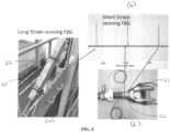
- FIGs. 8(a) - 8(c) and FIG. 10 illustrates sensor configurations as applied to the lashing rods 20.
- strain gauges are applied along a longitidinal axis of the lashing rods 20.
- the sensors 25, 26 depicted in FIGs. 8(a) - 8(c) and FIG. 10 are optical strain gauges (a suitable gauge for this purpose is the OS3100 optical strain gauge available from Micron Optics, Inc. of Atlanta, Georgia).
- the OS3100 optical strain gauge incorporates a fiber Bragg grating (FBG) configured as a fiber Fabry-Perot interferometer .
- FBG fiber Bragg grating
- FIG. 8(a) illustrates a first configuration not forming part of the present invention, in which a long strain-sensing gauge 25 is affixed to the turnbuckle 22 of the lashing rod 20.
- FIG. 8 (c) and FIG. 10 illustrate a second configuration in accordance with the present invention, in which a short strain-sensing gauge is affixed to the shackle 21 of the lashing rod 20. Strain is measured by sending a laser beam through the FBG sensor fitted on the lashing gear, and measuring the change in wavelength. For ease of identification, ach sensor is assigned a unique wavelength. This approach minimizes the amout of required cabling, and supports a modular, scalable infrastructure which is practical and easy to implement.
- Long strain gauge sensors 25 are fitted along the length of the turnbuckle 22 of the lashing gear 20. These gauges are fitted across the entire length of the turnbuckle 22 in longitudinal direction. The inventors determined however that this configuration is difficult to maintain since the turnbuckle needs to be rotated. Short strain gauge sensors 26 on the other hand are fitted on the lower shackle, after machining the surface. The inventors found that, while measurements are magnified for the long strain gauge sensors 25 as compared to the short strain gauge sensors 26, deviations were accurately captured in both cases. FIGs. 9(a) and 9(b) illustrate outputs for the long strain gauge sensors 25 and the short strain gauge sensors 26, respectively. As a result, the implementation uses the short strain gauge sensors 26.
- FIGs. 7(a) - 7(c) illustrate the measurement process.
- a measure of change in wavelength over time is obtained by the strain gauge.
- FIG. 7(b) illustrates the output of the isolates sensor, which indicates a change in wavelength over time due only to temperature effects.
- a second FBG sensor may be provided in proximity to the strain gauge but isolated from exposure to forces inducing strain.
- the change in wavelength due to temperature can simply be calculated to represent the output of FIG. 7(b) .
- a difference between the wavelength values illustrated in FIGs. 7(a) and 7(b) can then be calculated to determine temperature-compensated strain levels.
- FIGs. 12(a), 12(b) and 13 illustrate an overall architecture for the container lashing gear monitoring system.
- Each of the strain gauge sensors 24 and temperatures sensors are coupled via sensor cables 27 and sensor connectors 28 to backbone connectors 38 of an optical fiber backbone 37.
- Each backbone connector 38 connects sensors from several lashing rods 20 to the optical fiber backbone, which runs across the length of the ship in order to provide access to all containers onboard the ship.
- An interrogator unit 32 which is preferably housed within the ship, determines lashing rod strain from measurements provided by the sensors 24.
- the interrogator unit 32 is preferably implemented by a Hyperion s255 Hyperion Optical Sensing Instrument, available from Micron Optics, Inc. of Atlanta, Georgia.
- Individual sensors incorporate a light source having a unique wavelength, and thus are able to continuously and identifiably monitor changes in lashing rod tightness for monitored lashing rods 20.
- Each backbone connector 38 may for example connect up to 16 sensors to optical splines that are integrated with the backbone 37.
- Interrogator unit 32 is further coupled (for example, via LAN cable 35) to a general purpose computer 34 nd associated display 36 that funtion to provide a continuous monitoring display and alarm unit for the container lashing gear monitoring system.
- Continuous monitoring display and alarm unit 34, 36 may preferably display a dashboard that is used by operators to identify alert conditions. On this screen, an operator can see a current status of each lashing rod 20 (normal or alarm state), together with strain and historical data. For example, with reference to FIG.11 , the user is able to select a particular sensor 24 (ID No. 1512082126) that is assigned to a lashing rod 20 positioned at bay 3, row 7, tier 1.
- Graphic 40 depicts the location of the associated container 13 on deck 18 of the vessel 10.
- Graphic 42 indicates that a "tension warning” was initially issued indicating a tension level that exceeds a baseline value (0.58 nm"), and a "tension alert” was later issued when the exceeded baseline value remained for a predetermined number of measurement and/or time period.
- Interrogator unit 32 may be coupled to existing on-board monitoring and alert systems for the purpose of implementing the continuous monitoring display and alarm unit 34, 36.
- FIG. 6 illustrates an exemplary method for operating the container lashing gear monitoring system according to aspects of the present disclosure.
- suitable software At step 602 of the method, sensors 24 are identified and fitted to lashing rods 20 according to a selected desgin (for example, as depicted in FIG. 4(b) .
- thelashing gear 20 is tightened according to accepted specifications. 2
- sensor data is collected at a regular interval (for example, with a frequency of 1 Hz), and algorithms are applied to filter increases in strain force that are due only to ship movement.
- additional algorithma are applied to look for sustrained and gradual strains that are indicative of a loosening of associated lashing rods 20.
- an alert decision is made when the change and duration of strain exceed a threshold indicating a loosening of associated lashing rods 20.
- ship crew are dispatched to mitigate the loosening condition by re-tightening the associated lashing gear 20 to prescribed specifications.
Landscapes
- Physics & Mathematics (AREA)
- General Physics & Mathematics (AREA)
- Engineering & Computer Science (AREA)
- Mechanical Engineering (AREA)
- Chemical & Material Sciences (AREA)
- Combustion & Propulsion (AREA)
- Ocean & Marine Engineering (AREA)
- Transportation (AREA)
- Analytical Chemistry (AREA)
- Emergency Alarm Devices (AREA)
- Length Measuring Devices By Optical Means (AREA)
Description
- This disclosure relates generally to monitoring systems for restraints, and more particularly, to a tension monitoring system for lashing gear applied to containers on container vessels.
- A statement given by the World Shipping Council1 indicates that, during a survey period between 2014 and 2016, there were 612 containers lost at sea each year, excluding catastrophic loss. These losses happened despite routine checking of tension by the crews during the journies, and are most oftem are attributed to improper tensioning of lashing gear. Even in the cases where other causal factors are identified, the final component impacted before failure is the lashing gear.
FIG. 1 shows a container vessel that has experienced container movement (and likely losses) as a result of improperly-tensioned lashing gear. - It is difficult to monitor container lashing tightness when the vessel is sailing. Containers can get loose for several reasons, including routine flexing of ship structure, bad weather, poor workmanship in loading and securing containers on borard. Normally, a container ship has several thousand containers stacked on top of each other multi-row configuration. This configuration makes container monitoring difficult. At present, the only effective way to monitor containers is by manually checking them at certain intervals during the sailing voyage period.
- Manual systems for monitoring and maintaining lashing gear tension suffer several disadvantages. As the size of container ships increase over time, manual checking of tension during voyage becomes more costly, and is often not comprehensive and ineffective due to resource limitations. With increase in size of ships, it is not possible to visit each lashing rod with sufficient frequency to check its tightness. Even on a sampled basis, one estimate for example suggests manual checking require 2-3 hours time by two crew per day. Manual checking is also dangerous, with associated risks of crew falling overboard. One insurer estimates historical losses per lost container at between $100,000 to $1 million. Container losses may also generate an environmental impact with attendant costs (for example, from lost containers that are washed ashore).
- Indirect methods of monitoring container security such as measuring the hull deformation and container deformation have been proposed in past. They do not directly measure the lashing rod tightness, and hence do not address the problem effectively.
- It would be beneficial to develop a more effective and efficient system and method for monitoring and maintaining lashing gear tension.
Further background art can be found in the following documents:
WO 2005/075286 A1 discloses a method for monitoring the rigging of a sailing vessel. The method comprises a step for measuring elongation, wherein the elongation of at least part of a stay is measured. The invention furthermore relates to a stay provided with elongation-measuring means, such as an optical fibre for example, to a measuring device comprising elongation-measuring means which can be fastened to a stay, as well as to the use of the data which is obtained by the method for monitoring the rigging of a sailing vessel.
US 2018/319312 A1 discloses an automatic tension sensing and control system for cargo restraints comprises a load binder, a tension sensor, an actuator coupled to the load binder, and a control module. The control module receives signals from the sensor and can command the actuator to tighten or slacken the load binder. The system can also include an annunciator and an information storage and retrieval system.
US 2003/074978 A1 discloses a method and apparatus for monitoring and measuring the load in a sailboat's rigging components. A rigging component such as a turnbuckle is modified to incorporate a sensing element, such as a strain gage. Strain gages are bonded and wired into a measuring circuit. The strain gage measures the strain under a load and generates an electrical signal that is directly proportional to the tension load. The load is then monitored and/or displayed using standard data acquisition equipment. The strain gage also identifies loose rigging such as may happen with shrouds which are subject to sudden high loading with movement of the boat and allows the operator to tighten that shroud or other piece of rigging.
US 2003/154802 A1 discloses a strain transducer strand that is provided comprising an elongatable central core around which are helically wound one or more plastic tubes each of which contains an optical fibre. Each tube is overfilled with the optical fibre, such that the fibre is longer than the tube. As the transducer strand experiences strain, the core, plastic tubes, and optical fibres elongate, with the helical winding acting as gearing to produce a reduced elongation in the fibres proportional to the elongation of the transducer strand. The degree of elongation may be detected by monitoring the optical properties of light transmitted along the fibres. The transducer strand is particulary intended for incorporation into elongate load bearing members, such as ropes.
The book by D.J.HOUSE: "Seamanship Techniques; Shipboard and Maritime Operations", Third Edition 2004, ISBN: 0750663154 discloses further background art. - By way of example, aspects of the present disclosure are directed to disclose a novel system and method for remotely monitoring the lashing gear strain for containers being carried onboard ships ("SMARTLashing") using fiber optic sensors and other associated hardware and software systems.
- The present invention is defined by the appended independent claims. The dependent claims are directed to optional features and preferred embodiments. When a change in the value of stress or strain is indicative of loosened or overtightened restraint members, a mitigation event is triggered. The stress or strain analysis distinguishes intermittent changes indicating a vehicle movement from sustained, gradual changes indicating a restraint member that has either been loosened or overtightened.
- For a typical container ship carrying 1000 or more containers, in comparison to prior art methods requiring manual monitoring of container restraints, it is estimated that the system and method disclosed herein can reduce crew effort by 2-3 hrs. by 2 crew per day, prevent crew from falling overboard (
Fig. 1 ), and significantly reduce cost of associated insurance claims for injury and loss, which are estimated between $100k - $1 million per container loss. In addition, the impact on environment stemming from containers washed ashore can be substantially reduced. - This SUMMARY is provided to briefly identify some aspects of the present disclosure that are further described below in the DESCRIPTION. This SUMMARY is not intended to identify key or essential features of the present disclosure nor is it intended to limit the scope of any claims.
- A more complete understanding of the present disclosure may be realized by reference to the accompanying drawing in which:
-
FIG. 1 illustrates the impact improperly secured containers may exert on a container vessel; -
FIGs. 2(a) - 2(d) illustrate container lashing rod configurations in accordance with aspects of the present disclosure; -
FIGs. 3(a) - 3(c) further illustrate container lashing rod configurations in accordance with aspects of the present disclosure; -
FIGs. 4(a) - 4(c) illustrate container layouts to which lashing rods are applied in accordance with aspects of the present disclosure; -
FIGs. 5(a) and 5(b) illustrate strain sensor layouts in accordance with aspects of the present disclosure; -
FIG. 6 provides a flow diagram illustrating a process for maintaining a tightness of lashing gear in accordance with aspects of the present disclosure; -
FIGs. 7(a) - 7(c) illustrate exemplary sensor measures acquired for the purpose of measuring lashing rod strain in accordance with aspects of the present invention; -
FIGs. 8(a) - 8(c) illustrate a positioning of strain sensors on lashing rods in accordance with aspects of the present disclosure; -
FIGs. 9(a) and 9(b) illustrate exemplary sensor measures obtained from the sensors as positioned inFIGs. 8(a) - 8(c) ; -
FIG. 10 further illustrates a positioning of a strain sensors on lashing rod in accordance with aspects of the present disclosure; -
FIG. 11 provides an exemplary dashboard for monitoring lashing gear in accordance with aspects of the present disclosure; -
FIGs. 12(a) and 12(b) present schematic diagrams illustrating an exemplary cable layout for a lashing gear monitoring system in accordance with aspects of the present disclosure; and -
FIG. 13 further illustrates the exemplary layout ofFIGs. 12(a) and 12(b) . - The following merely illustrates the principles of the disclosure. It will thus be appreciated that those skilled in the art will be able to devise various arrangements which, although not explicitly described or shown herein, embody the principles of the disclosure and are included within its scope as defined by the appended claims.
- Furthermore, all examples and conditional language recited herein are principally intended expressly to be only for pedagogical purposes to aid the reader in understanding the principles of the disclosure and the concepts contributed by the inventor(s) to furthering the art, and are to be construed as being without limitation to such specifically recited examples and conditions.
- Unless otherwise explicitly specified herein, the drawings are not drawn to scale.
- Aspects of the present disclosure are directed to an inventive system and method for monitoring and maintaining lashing gear tension of a container vessel. Elements of the inventive system include lashing rods, optical strain sensors ("fiber Bragg grating" or "FBG" sensors), an interrogator unit for polling the optical strain sensors to obtain strain data, optical fiber cables for optical communications between the interrogator unit and strain sensors, and a general-purpose computer and monitor for operating the system.
- Some other non-optical strain monitoring solutions require extensive power cable networks on board ship, and are difficult to implement. Also, the environment on deck is often harsh, and components are required to be environmentally robust and explosion-proof. This makes many other possible strain monitoring solutions impractical to implement on board merchant vessels.
-
FIGs. 2(a) - 4(c) illustrate container lashing arrangements in accordance with aspects of the present disclosure. As shown for example inFIG. 3 ,containers 13 are arranged in column stacks 16 in which vertically adjacent ones of thecontainers 13 are fixedly fastened to one another. Column stacks 16 are subjected to a variety of forces (for example, resulting from wind and motion of thevessel 10 asea that can be characterized as one or more of pitch motion, heave motion and roll motion) which further require that the column stacks 16 be secured to thedeck 18 of thevessel 10. This is typically accomplished by mechanically fastening one or more containers in the column stack to thedeck 18 by means of lashingrods 20 that are preferably fastened at one end to a receptacle affixed to acontainer 13 and at the other end to a lashing bridge 11 that is integral with and/or afficxed to the deck 18 (see, e.g.,FIGs. 2(a) and 2(b) ). With reference toFIG. 10 , lashingrods 20 may preferably include a turnbuckle 22 with a threaded rod connected to ashackle 21 on one end, and a rod extending from the other end that terminates in asecond shackle 21. Theturnbuckle 22 provides a mechanism for loosening or tightening the lashingrods 20 in order to properly secure the associatedcontainers 13 to thedeck 18. In accordance with aspects of the present disclosure, and as depicted inFIG. 3(c) , suitable lashing gear may included a model ST-4508 knob/jaw turnbuckle and LB-44 lashing bar, both available from International Lashing Systems NV of Antwerp, Belgium. - Lashing
rods 20 are preferably applied in a selective manner to a limited number ofcontainers 13 to secure thecontainers 13 to thedeck 18.FIGs. 2(c) and 2(d) illustrate two nonlimiting examples of such selective applications. InFIG. 2(d) , twocrossing lashing rods 13 are attached to opposing lashing bridges 11 in proximity to alower containers 13. Theturnbuckles 22 are each coupled to a twin rod and shackle arrangement that is respectively coupled to one receptacle that is integral with an upper corner of thelower container 13 and to another shackle arrangement that is coupled to a second receptacle that is integral with a lower corner of a vertically adjacent container 13 (see, eg.,FIG. 2a ). An equalizing device (for example, toggle plate 21a) is preferably positioned between theturnbuckles 22 and twin rod and shackle arrangement to equalize the forces applied by each lashingrod 20 to the corners of the two containers. In the example ofFIG. 2(c) , apair lashing rods 20 are attached to each of the opposing lashing bridges 11, with one of the lashing rod pair being coupled to a receptacle that is integral with an upper corner of thelower container 13 and the other one of the lashing rod pair being coupled to a another receptacle that is integral with an upper corner of a verticallyadjacent container 13. -
FIGs. 4(a) - 4(c) illustrate a lashing rod monitoring scheme in accordance with aspects of the present invention. Atypical container vessel 10 may carry several thousand containers. A suitable monitoring scheme should ideally be capable of ensuring that lashing tightness of all containers is comprehensively covered without having the need to fit all lashing rods with sensors. For this purpose, the inventors determined by experimentation and by studying causal factors for container lashing becoming loose or tight that sensors could be applied to lashing rods associated with just two rings of the most vulnerable container stacks. As illustrated for example inFIGs. 4(a) - 4(c) , these rings includecontainers 13 occupying one or twotiers 12 of the outermost stack rows 14a on thedeck 18 of thecontainer vessel 10, and at least one tier of the outermost stack rows 15b having a highest stack weight. Other containers deemed to be especially vulnerable may optionally be added for monitroring as well. - The inventors further determined that the number of
sensors 24 used in each ring cant be selectively reduced without significantly impacting the ability of the system to detect tensioning anomalies for the lashingrods 20. Specifically, for example, as illustrated byFIG. 5(a) ,sensors 24 can alternatively be omitted on each of port and starboard sides fromadjacent bays 14, such that eachbay 14 hassensors 24 positioned on only one of the sides (port or starboard) of the bay. As another example illustrated byFIG. 5(b) , the sumber of sensors on port and starboard sides in each bay can be reduced (for example, eliminating sensors on either the for or aft lashingrods 20 on each side). -
FIGs. 8(a) - 8(c) andFIG. 10 , in accordance with aspects of the present disclosure, illustrates sensor configurations as applied to the lashingrods 20. As depicted, strain gauges are applied along a longitidinal axis of the lashingrods 20. The sensors 25, 26 depicted inFIGs. 8(a) - 8(c) andFIG. 10 are optical strain gauges (a suitable gauge for this purpose is the OS3100 optical strain gauge available from Micron Optics, Inc. of Atlanta, Georgia). The OS3100 optical strain gauge incorporates a fiber Bragg grating (FBG) configured as a fiber Fabry-Perot interferometer .FIG. 8(a) illustrates a first configuration not forming part of the present invention, in which a long strain-sensing gauge 25 is affixed to theturnbuckle 22 of the lashingrod 20.FIG. 8 (c) andFIG. 10 illustrate a second configuration in accordance with the present invention, in which a short strain-sensing gauge is affixed to theshackle 21 of the lashingrod 20. Strain is measured by sending a laser beam through the FBG sensor fitted on the lashing gear, and measuring the change in wavelength. For ease of identification, ach sensor is assigned a unique wavelength. This approach minimizes the amout of required cabling, and supports a modular, scalable infrastructure which is practical and easy to implement. - Long strain gauge sensors 25 are fitted along the length of the
turnbuckle 22 of thelashing gear 20. These gauges are fitted across the entire length of the turnbuckle 22 in longitudinal direction. The inventors determined however that this configuration is difficult to maintain since the turnbuckle needs to be rotated. Short strain gauge sensors 26 on the other hand are fitted on the lower shackle, after machining the surface. The inventors found that, while measurements are magnified for the long strain gauge sensors 25 as compared to the short strain gauge sensors 26, deviations were accurately captured in both cases.FIGs. 9(a) and 9(b) illustrate outputs for the long strain gauge sensors 25 and the short strain gauge sensors 26, respectively. As a result, the implementation uses the short strain gauge sensors 26. - Since the FBG sensors are very sensitive to variation in temperature, an additional sensor is used in each case for measuring temperature. Compensation for temperature is made to accurately measure strain due to movement of ship and other factors.
FIGs. 7(a) - 7(c) illustrate the measurement process. InFIG. 7(a) , a measure of change in wavelength over time is obtained by the strain gauge.FIG. 7(b) illustrates the output of the isolates sensor, which indicates a change in wavelength over time due only to temperature effects. In order to produce the output ofFIG. 7(b) , a second FBG sensor may be provided in proximity to the strain gauge but isolated from exposure to forces inducing strain. Alternatively, as optical fiber rates of expansion and contraction due to temperature are readily known, the change in wavelength due to temperature can simply be calculated to represent the output ofFIG. 7(b) . As illustrated inFIG. 7(c) , a difference between the wavelength values illustrated inFIGs. 7(a) and 7(b) can then be calculated to determine temperature-compensated strain levels. - In accordance with aspects of the present disclosure,
FIGs. 12(a), 12(b) and13 illustrate an overall architecture for the container lashing gear monitoring system. Each of thestrain gauge sensors 24 and temperatures sensors are coupled via sensor cables 27 and sensor connectors 28 tobackbone connectors 38 of an optical fiber backbone 37. Eachbackbone connector 38 connects sensors from several lashingrods 20 to the optical fiber backbone, which runs across the length of the ship in order to provide access to all containers onboard the ship. - An
interrogator unit 32, which is preferably housed within the ship, determines lashing rod strain from measurements provided by thesensors 24. Theinterrogator unit 32 is preferably implemented by a Hyperion s255 Hyperion Optical Sensing Instrument, available from Micron Optics, Inc. of Atlanta, Georgia. Individual sensors incorporate a light source having a unique wavelength, and thus are able to continuously and identifiably monitor changes in lashing rod tightness for monitored lashingrods 20. Eachbackbone connector 38 may for example connect up to 16 sensors to optical splines that are integrated with the backbone 37. - Some of the
sensors 24 are fixedly attached to theconnectors 38, and some are additionally connected to theconnectors 38 via one or more free ports 33.Interrogator unit 32 is further coupled (for example, via LAN cable 35) to a general purpose computer 34 nd associated display 36 that funtion to provide a continuous monitoring display and alarm unit for the container lashing gear monitoring system. - Continuous monitoring display and alarm unit 34, 36 may preferably display a dashboard that is used by operators to identify alert conditions. On this screen, an operator can see a current status of each lashing rod 20 (normal or alarm state), together with strain and historical data. For example, with reference to
FIG.11 , the user is able to select a particular sensor 24 (ID No. 1512082126) that is assigned to a lashingrod 20 positioned atbay 3,row 7, tier 1. Graphic 40 depicts the location of the associatedcontainer 13 ondeck 18 of thevessel 10.Graphic 42 indicates that a "tension warning" was initially issued indicating a tension level that exceeds a baseline value (0.58 nm"), and a "tension alert" was later issued when the exceeded baseline value remained for a predetermined number of measurement and/or time period. One of skill in the art will readily envision many other modes of display are possible for the monitoring and alarm functions. It is possbile thatInterrogator unit 32 may be coupled to existing on-board monitoring and alert systems for the purpose of implementing the continuous monitoring display and alarm unit 34, 36. -
FIG. 6 illustrates an exemplary method for operating the container lashing gear monitoring system according to aspects of the present disclosure. suitable software. At step 602 of the method,sensors 24 are identified and fitted to lashingrods 20 according to a selected desgin (for example, as depicted inFIG. 4(b) . At step 604,thelashing gear 20 is tightened according to accepted specifications.2 At step 606, sensor data is collected at a regular interval (for example, with a frequency of 1 Hz), and algorithms are applied to filter increases in strain force that are due only to ship movement. At step 608, additional algorithma are applied to look for sustrained and gradual strains that are indicative of a loosening of associated lashingrods 20. At step 610, an alert decision is made when the change and duration of strain exceed a threshold indicating a loosening of associated lashingrods 20. At step 612, upon receipt of the alert, ship crew are dispatched to mitigate the loosening condition by re-tightening the associatedlashing gear 20 to prescribed specifications. - It will be understood that, while various aspects of the present disclosure have been illustrated and described by way of example, the invention claimed herein is not limited thereto, but may be otherwise variously embodied within the scope of the following claims. For example, the system may be readily adapted for application to other mechanical systems both onboard the vessel 10 (including engine rooms) and/oror other operating environments - for example, including tie rods, foundation bolts and other long bolting arrangements subject to cyclic stress and strain.
- The following table lists the reference characters and names of features and elements used herein: Reference characters assigned to method steps are not listed.
Ref. char. Feature or element 14 Bay 27 Cable 16 Column Stack 34 Computer 36 Computer Monitor 28 Connector - Sensor 38 Connector 13 Container 14 Container Row 14a Container Row - Outermost on Deck 14b Container Row - Outermost with Highest Stack Weight 18 Deck 24 Fiber Bragg Grating (FBG) Sensor 31 Fixed Sensor 32 Interrogator Unit 11 Lashing Bridge 20 Lashing Rod 35 Local Area Network (LAN) cable 30 Monitoring System 23 Mounting Plate 37 Optical Fiber Backbone 33 Port 27 Sensor Connector 21 Shackle 25 Strain Gauge - Long 26 Strain Gauge - Short 12 Tier 21a Toggle Plate 22 Turnbuckle 10 Vessel
Claims (5)
- A system for monitoring restraint of one or more containers that have been restrainedly secured to a container ship by one or more restraint members, the system comprising:the one or more containers (13);the one or more restraint members (20) for restraining respective ones of the one or more containers, wherein the one or more restraint members (20) each comprise a turnbuckle member (22) configured for fastening to a fixed point on the container ship via a shackle or fork member (21);a plurality of sensors (26) each configured for monitoring one or more of a compressive or tensile stress or strain in one of the one or more restraint members (20) wherein each of the plurality of sensors (26) is fitted on the shackle or fork member (21) of the turnbuckle member for monitoring stress or strain in one of the turnbuckle members (22);a controller (32) for periodically interrogating each of the plurality of sensors (26) to ascertain a value of stress or strain detected by the respective sensor; anda computing device (34) coupled to the controller,characterized in thateach of the plurality of sensors (26) comprise a Fiber Bragg Grating (FBG) sensor configured for measuring the stress or the strain in one of the turnbuckle members (22);wherein the one or more containers (13) that are secured by restraint members (20) having sensors (26) for monitoring one or more of compressive or tensile stress or strain are a subset of containers on the container ship;the computing device (34) determines whether the value of stress or strain ascertained by the controller satisfies a threshold condition in the FBG sensors.
- The system of the preceding claim further comprising at least one temperature compensation sensor configured for adjusting stress or strain values detected by one or more of the plurality of sensors.
- A method for monitoring restraint of one or more containers that have been restrainedly secured to a container ship by one or more restraint members (20), the method comprising the steps of:providing a plurality of sensors (26), each of the plurality of sensors fitted on a shackle or fork member (21) of a turnbuckle member (22) of a respective one of the one or more restraint members, the turnbuckle member (22) fastening a respective one of the one or more containers (13) to a fixed point on the container ship, characterized in that:each of the plurality of sensors (26) comprise a Fiber Bragg Grating (FBG) sensor configured for measuring the stress or the strain in one of the turnbuckle members (22);wherein the one or more containers (13) that are secured by restraint members (20) having sensors (26) for monitoring one or more of compressive or tensile stress or strain are a subset of containers on the container ship; andconfiguring a controller (32) for periodically interrogating each of the plurality of sensors to ascertain a value of stress or strain detected by the respective sensor;determining whether the value of stress or strain detected by each FBG sensor (26) of the plurality of sensors satisfies a threshold condition and;setting an alert condition when the threshold condition has been satisfied for at least one FBG sensor (26) of the plurality of sensors.
- The method of claim 3, further comprising the step of:
providing at least one temperature compensation sensor configured for adjusting stress or strain values detected by one or more of the plurality of sensors. - The method of claim 3, wherein the alert condition is only set when the threshold condition has been satisfied continuously over a predetermined number of time-successive interrogations of the at least one respective FBG sensor of the plurality of sensors.
Applications Claiming Priority (2)
| Application Number | Priority Date | Filing Date | Title |
|---|---|---|---|
| US201962798331P | 2019-01-29 | 2019-01-29 | |
| PCT/IB2020/000075 WO2020157578A1 (en) | 2019-01-29 | 2020-01-29 | Container lashing gear monitoring system |
Publications (4)
| Publication Number | Publication Date |
|---|---|
| EP3917802A1 EP3917802A1 (en) | 2021-12-08 |
| EP3917802A4 EP3917802A4 (en) | 2022-11-30 |
| EP3917802C0 EP3917802C0 (en) | 2025-06-25 |
| EP3917802B1 true EP3917802B1 (en) | 2025-06-25 |
Family
ID=71841733
Family Applications (1)
| Application Number | Title | Priority Date | Filing Date |
|---|---|---|---|
| EP20748336.3A Active EP3917802B1 (en) | 2019-01-29 | 2020-01-29 | Container lashing gear monitoring system |
Country Status (5)
| Country | Link |
|---|---|
| US (1) | US11650116B2 (en) |
| EP (1) | EP3917802B1 (en) |
| AU (1) | AU2020215319A1 (en) |
| SG (1) | SG11202107672PA (en) |
| WO (1) | WO2020157578A1 (en) |
Families Citing this family (6)
| Publication number | Priority date | Publication date | Assignee | Title |
|---|---|---|---|---|
| US11208027B1 (en) * | 2019-01-28 | 2021-12-28 | Michael D. Rainone | Automated, wireless, cargo restraint tension control and monitoring system |
| CN113834534B (en) * | 2021-10-22 | 2024-07-26 | 南京杰曼绑扎件制造有限公司 | Real ship inspection method for container ship binding system |
| US12194909B2 (en) * | 2021-10-25 | 2025-01-14 | Trendsetter Vulcan Offshore, Inc. | Monitoring system designed to extract critical natural frequencies of a cargo ship |
| CN114374982B (en) * | 2022-01-05 | 2023-12-19 | 上海船舶运输科学研究所有限公司 | An antenna arrangement method in the deck area of a container ship |
| CN116767712B (en) * | 2023-07-24 | 2026-04-14 | 北斗启明(北京)节能科技服务有限公司 | Storage tank flexible bag cover operation safety monitoring system based on fracture alarm |
| CN119734799B (en) * | 2024-08-21 | 2026-02-06 | 中国船舶集团有限公司第七○八研究所 | An intelligent monitoring system for improving cargo transport safety on container ships |
Family Cites Families (10)
| Publication number | Priority date | Publication date | Assignee | Title |
|---|---|---|---|---|
| GB2027542B (en) * | 1978-08-08 | 1983-03-23 | Derwent Measurement & Control | Calibrating a weighting device |
| GB0014936D0 (en) | 2000-06-20 | 2000-08-09 | Univ Strathclyde | Strain transducer |
| US6543296B1 (en) * | 2001-10-18 | 2003-04-08 | Ricardo J. Bermudez | Method of monitoring/measuring rigging loads |
| WO2005075286A1 (en) | 2004-02-04 | 2005-08-18 | Rinze-Jan Van Der Schuit | Method for monitoring the rigging of a sailing vessel, stay and measuring device for this method, as well as use of data obtained by this method |
| US8314925B2 (en) * | 2009-10-30 | 2012-11-20 | General Electric Company | Fiber-optic based thrust load measurement system |
| DE102013006486A1 (en) * | 2013-03-09 | 2014-09-11 | Karl-Heinz Grüter | Load securing with tension straps and chain hoists |
| JP6277024B2 (en) * | 2014-03-17 | 2018-02-07 | 三菱航空機株式会社 | Aircraft strength test apparatus and strength test method |
| WO2017037512A1 (en) | 2015-09-04 | 2017-03-09 | Psa International Pte Ltd | Container lashing process and system |
| US10814773B1 (en) * | 2016-10-18 | 2020-10-27 | Michael D. Rainone | Automated, wireless, cargo restraint tension control and monitoring system |
| US10239439B2 (en) * | 2017-05-03 | 2019-03-26 | Pacific States Manufacturing, Inc. | Tension monitoring and signaling system |
-
2020
- 2020-01-29 AU AU2020215319A patent/AU2020215319A1/en not_active Abandoned
- 2020-01-29 WO PCT/IB2020/000075 patent/WO2020157578A1/en not_active Ceased
- 2020-01-29 US US16/776,080 patent/US11650116B2/en active Active
- 2020-01-29 SG SG11202107672PA patent/SG11202107672PA/en unknown
- 2020-01-29 EP EP20748336.3A patent/EP3917802B1/en active Active
Also Published As
| Publication number | Publication date |
|---|---|
| EP3917802A4 (en) | 2022-11-30 |
| EP3917802A1 (en) | 2021-12-08 |
| EP3917802C0 (en) | 2025-06-25 |
| WO2020157578A1 (en) | 2020-08-06 |
| US11650116B2 (en) | 2023-05-16 |
| SG11202107672PA (en) | 2021-08-30 |
| AU2020215319A1 (en) | 2021-08-12 |
| US20200264061A1 (en) | 2020-08-20 |
Similar Documents
| Publication | Publication Date | Title |
|---|---|---|
| EP3917802B1 (en) | Container lashing gear monitoring system | |
| Read et al. | Sea and flight trials of optical fibre Bragg grating strain sensing systems | |
| JP6463028B2 (en) | Load / stress monitoring method for floating facilities and load / stress monitoring system for floating facilities | |
| US6543296B1 (en) | Method of monitoring/measuring rigging loads | |
| GB2456831A (en) | Fatigue and damage monitoring of pipes before and during installation | |
| Phelps et al. | Review of hull structural monitoring systems for navy ships | |
| KR101726500B1 (en) | Apparatus and method for vessel monitoring | |
| JP5928842B2 (en) | Fender load monitoring | |
| WO2026045005A1 (en) | Intelligent oil tanker mooring system and use method therefor | |
| KR101549236B1 (en) | Ship hull strength monitoring system | |
| Fanelli et al. | Live reconstruction of global loads on a powerboat using local strain FBG measurements | |
| JP5355228B2 (en) | Telephone pole stress management system | |
| KR20230023843A (en) | Hull Fatigue Failure Prediction System By Slamming Laod Using Digital Twin | |
| Sagvolden et al. | Fiber optic system for ship hull monitoring | |
| Kiddy et al. | Structural load monitoring of the RV Triton using fiber optic sensors | |
| JP4505395B2 (en) | Marine transportation monitoring system | |
| GB2278446A (en) | Hull monitoring apparatus and method | |
| DE102008028301A1 (en) | Method for monitoring the condition of a ship's hull | |
| KR20080018229A (en) | Integrated meteorological / load monitoring system for container cranes | |
| Cusano et al. | Evaluation and Forecasting of Elapsed Fatigue Life of Ship Structures by Analyzing Data from Full Scale Ship Structural Monitoring | |
| Wines et al. | Ship Hull Monitoring System Applied as a Real Time Decision Support System on Fast Ferries | |
| CN220583640U (en) | Hull structure stress monitoring system | |
| CN119734799B (en) | An intelligent monitoring system for improving cargo transport safety on container ships | |
| Blanke et al. | Statistical change detection for diagnosis of buoyancy element defects on moored floating vessels | |
| Doyle et al. | Application of optical fibre sensors for marine structural monitoring |
Legal Events
| Date | Code | Title | Description |
|---|---|---|---|
| STAA | Information on the status of an ep patent application or granted ep patent |
Free format text: STATUS: THE INTERNATIONAL PUBLICATION HAS BEEN MADE |
|
| PUAI | Public reference made under article 153(3) epc to a published international application that has entered the european phase |
Free format text: ORIGINAL CODE: 0009012 |
|
| STAA | Information on the status of an ep patent application or granted ep patent |
Free format text: STATUS: REQUEST FOR EXAMINATION WAS MADE |
|
| 17P | Request for examination filed |
Effective date: 20210721 |
|
| AK | Designated contracting states |
Kind code of ref document: A1 Designated state(s): AL AT BE BG CH CY CZ DE DK EE ES FI FR GB GR HR HU IE IS IT LI LT LU LV MC MK MT NL NO PL PT RO RS SE SI SK SM TR |
|
| DAV | Request for validation of the european patent (deleted) | ||
| DAX | Request for extension of the european patent (deleted) | ||
| A4 | Supplementary search report drawn up and despatched |
Effective date: 20221031 |
|
| RIC1 | Information provided on ipc code assigned before grant |
Ipc: G01L 5/103 20200101ALI20221025BHEP Ipc: G01L 5/105 20200101ALI20221025BHEP Ipc: G01L 1/24 20060101ALI20221025BHEP Ipc: B65D 90/48 20060101ALI20221025BHEP Ipc: B60P 7/08 20060101ALI20221025BHEP Ipc: B60P 7/13 20060101AFI20221025BHEP |
|
| REG | Reference to a national code |
Ref country code: DE Ref legal event code: R079 Ref country code: DE Ref legal event code: R079 Ref document number: 602020053333 Country of ref document: DE Free format text: PREVIOUS MAIN CLASS: B60P0007130000 Ipc: G01L0001240000 |
|
| GRAP | Despatch of communication of intention to grant a patent |
Free format text: ORIGINAL CODE: EPIDOSNIGR1 |
|
| STAA | Information on the status of an ep patent application or granted ep patent |
Free format text: STATUS: GRANT OF PATENT IS INTENDED |
|
| RIC1 | Information provided on ipc code assigned before grant |
Ipc: B60P 7/08 20060101ALI20241220BHEP Ipc: B60P 7/13 20060101ALI20241220BHEP Ipc: B63B 79/10 20200101ALI20241220BHEP Ipc: B63B 25/28 20060101ALI20241220BHEP Ipc: B63B 79/40 20200101ALI20241220BHEP Ipc: G01L 5/105 20200101ALI20241220BHEP Ipc: G01L 5/103 20200101ALI20241220BHEP Ipc: G01L 1/24 20060101AFI20241220BHEP |
|
| INTG | Intention to grant announced |
Effective date: 20250117 |
|
| GRAS | Grant fee paid |
Free format text: ORIGINAL CODE: EPIDOSNIGR3 |
|
| GRAA | (expected) grant |
Free format text: ORIGINAL CODE: 0009210 |
|
| STAA | Information on the status of an ep patent application or granted ep patent |
Free format text: STATUS: THE PATENT HAS BEEN GRANTED |
|
| AK | Designated contracting states |
Kind code of ref document: B1 Designated state(s): AL AT BE BG CH CY CZ DE DK EE ES FI FR GB GR HR HU IE IS IT LI LT LU LV MC MK MT NL NO PL PT RO RS SE SI SK SM TR |
|
| REG | Reference to a national code |
Ref country code: GB Ref legal event code: FG4D |
|
| REG | Reference to a national code |
Ref country code: CH Ref legal event code: EP |
|
| REG | Reference to a national code |
Ref country code: CH Ref legal event code: EP |
|
| REG | Reference to a national code |
Ref country code: IE Ref legal event code: FG4D |
|
| REG | Reference to a national code |
Ref country code: DE Ref legal event code: R096 Ref document number: 602020053333 Country of ref document: DE |
|
| U01 | Request for unitary effect filed |
Effective date: 20250722 |
|
| U07 | Unitary effect registered |
Designated state(s): AT BE BG DE DK EE FI FR IT LT LU LV MT NL PT RO SE SI Effective date: 20250826 |
|
| PG25 | Lapsed in a contracting state [announced via postgrant information from national office to epo] |
Ref country code: NO Free format text: LAPSE BECAUSE OF FAILURE TO SUBMIT A TRANSLATION OF THE DESCRIPTION OR TO PAY THE FEE WITHIN THE PRESCRIBED TIME-LIMIT Effective date: 20250925 Ref country code: GR Free format text: LAPSE BECAUSE OF FAILURE TO SUBMIT A TRANSLATION OF THE DESCRIPTION OR TO PAY THE FEE WITHIN THE PRESCRIBED TIME-LIMIT Effective date: 20250926 |
|
| PG25 | Lapsed in a contracting state [announced via postgrant information from national office to epo] |
Ref country code: HR Free format text: LAPSE BECAUSE OF FAILURE TO SUBMIT A TRANSLATION OF THE DESCRIPTION OR TO PAY THE FEE WITHIN THE PRESCRIBED TIME-LIMIT Effective date: 20250625 |
|
| PG25 | Lapsed in a contracting state [announced via postgrant information from national office to epo] |
Ref country code: RS Free format text: LAPSE BECAUSE OF FAILURE TO SUBMIT A TRANSLATION OF THE DESCRIPTION OR TO PAY THE FEE WITHIN THE PRESCRIBED TIME-LIMIT Effective date: 20250925 |
|
| PG25 | Lapsed in a contracting state [announced via postgrant information from national office to epo] |
Ref country code: IS Free format text: LAPSE BECAUSE OF FAILURE TO SUBMIT A TRANSLATION OF THE DESCRIPTION OR TO PAY THE FEE WITHIN THE PRESCRIBED TIME-LIMIT Effective date: 20251025 |
|
| PG25 | Lapsed in a contracting state [announced via postgrant information from national office to epo] |
Ref country code: SM Free format text: LAPSE BECAUSE OF FAILURE TO SUBMIT A TRANSLATION OF THE DESCRIPTION OR TO PAY THE FEE WITHIN THE PRESCRIBED TIME-LIMIT Effective date: 20250625 |
|
| PG25 | Lapsed in a contracting state [announced via postgrant information from national office to epo] |
Ref country code: CZ Free format text: LAPSE BECAUSE OF FAILURE TO SUBMIT A TRANSLATION OF THE DESCRIPTION OR TO PAY THE FEE WITHIN THE PRESCRIBED TIME-LIMIT Effective date: 20250625 |
|
| PG25 | Lapsed in a contracting state [announced via postgrant information from national office to epo] |
Ref country code: PL Free format text: LAPSE BECAUSE OF FAILURE TO SUBMIT A TRANSLATION OF THE DESCRIPTION OR TO PAY THE FEE WITHIN THE PRESCRIBED TIME-LIMIT Effective date: 20250625 |
|
| PG25 | Lapsed in a contracting state [announced via postgrant information from national office to epo] |
Ref country code: SK Free format text: LAPSE BECAUSE OF FAILURE TO SUBMIT A TRANSLATION OF THE DESCRIPTION OR TO PAY THE FEE WITHIN THE PRESCRIBED TIME-LIMIT Effective date: 20250625 |
|
| PG25 | Lapsed in a contracting state [announced via postgrant information from national office to epo] |
Ref country code: ES Free format text: LAPSE BECAUSE OF FAILURE TO SUBMIT A TRANSLATION OF THE DESCRIPTION OR TO PAY THE FEE WITHIN THE PRESCRIBED TIME-LIMIT Effective date: 20250625 |
|
| U20 | Renewal fee for the european patent with unitary effect paid |
Year of fee payment: 7 Effective date: 20260130 |
|
| PLBE | No opposition filed within time limit |
Free format text: ORIGINAL CODE: 0009261 |
|
| STAA | Information on the status of an ep patent application or granted ep patent |
Free format text: STATUS: NO OPPOSITION FILED WITHIN TIME LIMIT |