EP3917759B1 - Verfahren zum herstellen eines luftführungs-bauteils - Google Patents
Verfahren zum herstellen eines luftführungs-bauteils Download PDFInfo
- Publication number
- EP3917759B1 EP3917759B1 EP20713883.5A EP20713883A EP3917759B1 EP 3917759 B1 EP3917759 B1 EP 3917759B1 EP 20713883 A EP20713883 A EP 20713883A EP 3917759 B1 EP3917759 B1 EP 3917759B1
- Authority
- EP
- European Patent Office
- Prior art keywords
- shells
- heated
- heating element
- air
- component
- Prior art date
- Legal status (The legal status is an assumption and is not a legal conclusion. Google has not performed a legal analysis and makes no representation as to the accuracy of the status listed.)
- Active
Links
Images



Classifications
-
- B—PERFORMING OPERATIONS; TRANSPORTING
- B29—WORKING OF PLASTICS; WORKING OF SUBSTANCES IN A PLASTIC STATE IN GENERAL
- B29C—SHAPING OR JOINING OF PLASTICS; SHAPING OF MATERIAL IN A PLASTIC STATE, NOT OTHERWISE PROVIDED FOR; AFTER-TREATMENT OF THE SHAPED PRODUCTS, e.g. REPAIRING
- B29C65/00—Joining or sealing of preformed parts, e.g. welding of plastics materials; Apparatus therefor
- B29C65/02—Joining or sealing of preformed parts, e.g. welding of plastics materials; Apparatus therefor by heating, with or without pressure
- B29C65/14—Joining or sealing of preformed parts, e.g. welding of plastics materials; Apparatus therefor by heating, with or without pressure using wave energy, i.e. electromagnetic radiation, or particle radiation
- B29C65/1403—Joining or sealing of preformed parts, e.g. welding of plastics materials; Apparatus therefor by heating, with or without pressure using wave energy, i.e. electromagnetic radiation, or particle radiation characterised by the type of electromagnetic or particle radiation
- B29C65/1412—Infrared [IR] radiation
-
- B—PERFORMING OPERATIONS; TRANSPORTING
- B29—WORKING OF PLASTICS; WORKING OF SUBSTANCES IN A PLASTIC STATE IN GENERAL
- B29C—SHAPING OR JOINING OF PLASTICS; SHAPING OF MATERIAL IN A PLASTIC STATE, NOT OTHERWISE PROVIDED FOR; AFTER-TREATMENT OF THE SHAPED PRODUCTS, e.g. REPAIRING
- B29C65/00—Joining or sealing of preformed parts, e.g. welding of plastics materials; Apparatus therefor
- B29C65/02—Joining or sealing of preformed parts, e.g. welding of plastics materials; Apparatus therefor by heating, with or without pressure
- B29C65/10—Joining or sealing of preformed parts, e.g. welding of plastics materials; Apparatus therefor by heating, with or without pressure using hot gases (e.g. combustion gases) or flames coming in contact with at least one of the parts to be joined
- B29C65/103—Joining or sealing of preformed parts, e.g. welding of plastics materials; Apparatus therefor by heating, with or without pressure using hot gases (e.g. combustion gases) or flames coming in contact with at least one of the parts to be joined direct heating both surfaces to be joined
-
- B—PERFORMING OPERATIONS; TRANSPORTING
- B29—WORKING OF PLASTICS; WORKING OF SUBSTANCES IN A PLASTIC STATE IN GENERAL
- B29C—SHAPING OR JOINING OF PLASTICS; SHAPING OF MATERIAL IN A PLASTIC STATE, NOT OTHERWISE PROVIDED FOR; AFTER-TREATMENT OF THE SHAPED PRODUCTS, e.g. REPAIRING
- B29C65/00—Joining or sealing of preformed parts, e.g. welding of plastics materials; Apparatus therefor
- B29C65/02—Joining or sealing of preformed parts, e.g. welding of plastics materials; Apparatus therefor by heating, with or without pressure
- B29C65/18—Joining or sealing of preformed parts, e.g. welding of plastics materials; Apparatus therefor by heating, with or without pressure using heated tools
- B29C65/24—Joining or sealing of preformed parts, e.g. welding of plastics materials; Apparatus therefor by heating, with or without pressure using heated tools characterised by the means for heating the tool
-
- B—PERFORMING OPERATIONS; TRANSPORTING
- B29—WORKING OF PLASTICS; WORKING OF SUBSTANCES IN A PLASTIC STATE IN GENERAL
- B29C—SHAPING OR JOINING OF PLASTICS; SHAPING OF MATERIAL IN A PLASTIC STATE, NOT OTHERWISE PROVIDED FOR; AFTER-TREATMENT OF THE SHAPED PRODUCTS, e.g. REPAIRING
- B29C65/00—Joining or sealing of preformed parts, e.g. welding of plastics materials; Apparatus therefor
- B29C65/78—Means for handling the parts to be joined, e.g. for making containers or hollow articles, e.g. means for handling sheets, plates, web-like materials, tubular articles, hollow articles or elements to be joined therewith; Means for discharging the joined articles from the joining apparatus
- B29C65/7841—Holding or clamping means for handling purposes
-
- B—PERFORMING OPERATIONS; TRANSPORTING
- B29—WORKING OF PLASTICS; WORKING OF SUBSTANCES IN A PLASTIC STATE IN GENERAL
- B29C—SHAPING OR JOINING OF PLASTICS; SHAPING OF MATERIAL IN A PLASTIC STATE, NOT OTHERWISE PROVIDED FOR; AFTER-TREATMENT OF THE SHAPED PRODUCTS, e.g. REPAIRING
- B29C66/00—General aspects of processes or apparatus for joining preformed parts
- B29C66/01—General aspects dealing with the joint area or with the area to be joined
- B29C66/05—Particular design of joint configurations
- B29C66/10—Particular design of joint configurations particular design of the joint cross-sections
- B29C66/11—Joint cross-sections comprising a single joint-segment, i.e. one of the parts to be joined comprising a single joint-segment in the joint cross-section
- B29C66/114—Single butt joints
- B29C66/1142—Single butt to butt joints
-
- B—PERFORMING OPERATIONS; TRANSPORTING
- B29—WORKING OF PLASTICS; WORKING OF SUBSTANCES IN A PLASTIC STATE IN GENERAL
- B29C—SHAPING OR JOINING OF PLASTICS; SHAPING OF MATERIAL IN A PLASTIC STATE, NOT OTHERWISE PROVIDED FOR; AFTER-TREATMENT OF THE SHAPED PRODUCTS, e.g. REPAIRING
- B29C66/00—General aspects of processes or apparatus for joining preformed parts
- B29C66/01—General aspects dealing with the joint area or with the area to be joined
- B29C66/05—Particular design of joint configurations
- B29C66/301—Three-dimensional joints, i.e. the joined area being substantially non-flat
-
- B—PERFORMING OPERATIONS; TRANSPORTING
- B29—WORKING OF PLASTICS; WORKING OF SUBSTANCES IN A PLASTIC STATE IN GENERAL
- B29C—SHAPING OR JOINING OF PLASTICS; SHAPING OF MATERIAL IN A PLASTIC STATE, NOT OTHERWISE PROVIDED FOR; AFTER-TREATMENT OF THE SHAPED PRODUCTS, e.g. REPAIRING
- B29C66/00—General aspects of processes or apparatus for joining preformed parts
- B29C66/50—General aspects of joining tubular articles; General aspects of joining long products, i.e. bars or profiled elements; General aspects of joining single elements to tubular articles, hollow articles or bars; General aspects of joining several hollow-preforms to form hollow or tubular articles
- B29C66/51—Joining tubular articles, profiled elements or bars; Joining single elements to tubular articles, hollow articles or bars; Joining several hollow-preforms to form hollow or tubular articles
- B29C66/54—Joining several hollow-preforms, e.g. half-shells, to form hollow articles, e.g. for making balls, containers; Joining several hollow-preforms, e.g. half-cylinders, to form tubular articles
- B29C66/543—Joining several hollow-preforms, e.g. half-shells, to form hollow articles, e.g. for making balls, containers; Joining several hollow-preforms, e.g. half-cylinders, to form tubular articles joining more than two hollow-preforms to form said hollow articles
-
- B—PERFORMING OPERATIONS; TRANSPORTING
- B29—WORKING OF PLASTICS; WORKING OF SUBSTANCES IN A PLASTIC STATE IN GENERAL
- B29C—SHAPING OR JOINING OF PLASTICS; SHAPING OF MATERIAL IN A PLASTIC STATE, NOT OTHERWISE PROVIDED FOR; AFTER-TREATMENT OF THE SHAPED PRODUCTS, e.g. REPAIRING
- B29C66/00—General aspects of processes or apparatus for joining preformed parts
- B29C66/70—General aspects of processes or apparatus for joining preformed parts characterised by the composition, physical properties or the structure of the material of the parts to be joined; Joining with non-plastics material
- B29C66/72—General aspects of processes or apparatus for joining preformed parts characterised by the composition, physical properties or the structure of the material of the parts to be joined; Joining with non-plastics material characterised by the structure of the material of the parts to be joined
- B29C66/727—General aspects of processes or apparatus for joining preformed parts characterised by the composition, physical properties or the structure of the material of the parts to be joined; Joining with non-plastics material characterised by the structure of the material of the parts to be joined being porous, e.g. foam
-
- B—PERFORMING OPERATIONS; TRANSPORTING
- B29—WORKING OF PLASTICS; WORKING OF SUBSTANCES IN A PLASTIC STATE IN GENERAL
- B29C—SHAPING OR JOINING OF PLASTICS; SHAPING OF MATERIAL IN A PLASTIC STATE, NOT OTHERWISE PROVIDED FOR; AFTER-TREATMENT OF THE SHAPED PRODUCTS, e.g. REPAIRING
- B29C66/00—General aspects of processes or apparatus for joining preformed parts
- B29C66/80—General aspects of machine operations or constructions and parts thereof
- B29C66/81—General aspects of the pressing elements, i.e. the elements applying pressure on the parts to be joined in the area to be joined, e.g. the welding jaws or clamps
- B29C66/814—General aspects of the pressing elements, i.e. the elements applying pressure on the parts to be joined in the area to be joined, e.g. the welding jaws or clamps characterised by the design of the pressing elements, e.g. of the welding jaws or clamps
- B29C66/8141—General aspects of the pressing elements, i.e. the elements applying pressure on the parts to be joined in the area to be joined, e.g. the welding jaws or clamps characterised by the design of the pressing elements, e.g. of the welding jaws or clamps characterised by the surface geometry of the part of the pressing elements, e.g. welding jaws or clamps, coming into contact with the parts to be joined
- B29C66/81411—General aspects of the pressing elements, i.e. the elements applying pressure on the parts to be joined in the area to be joined, e.g. the welding jaws or clamps characterised by the design of the pressing elements, e.g. of the welding jaws or clamps characterised by the surface geometry of the part of the pressing elements, e.g. welding jaws or clamps, coming into contact with the parts to be joined characterised by its cross-section, e.g. transversal or longitudinal, being non-flat
- B29C66/81421—General aspects of the pressing elements, i.e. the elements applying pressure on the parts to be joined in the area to be joined, e.g. the welding jaws or clamps characterised by the design of the pressing elements, e.g. of the welding jaws or clamps characterised by the surface geometry of the part of the pressing elements, e.g. welding jaws or clamps, coming into contact with the parts to be joined characterised by its cross-section, e.g. transversal or longitudinal, being non-flat being convex or concave
- B29C66/81422—General aspects of the pressing elements, i.e. the elements applying pressure on the parts to be joined in the area to be joined, e.g. the welding jaws or clamps characterised by the design of the pressing elements, e.g. of the welding jaws or clamps characterised by the surface geometry of the part of the pressing elements, e.g. welding jaws or clamps, coming into contact with the parts to be joined characterised by its cross-section, e.g. transversal or longitudinal, being non-flat being convex or concave being convex
-
- B—PERFORMING OPERATIONS; TRANSPORTING
- B29—WORKING OF PLASTICS; WORKING OF SUBSTANCES IN A PLASTIC STATE IN GENERAL
- B29C—SHAPING OR JOINING OF PLASTICS; SHAPING OF MATERIAL IN A PLASTIC STATE, NOT OTHERWISE PROVIDED FOR; AFTER-TREATMENT OF THE SHAPED PRODUCTS, e.g. REPAIRING
- B29C66/00—General aspects of processes or apparatus for joining preformed parts
- B29C66/80—General aspects of machine operations or constructions and parts thereof
- B29C66/81—General aspects of the pressing elements, i.e. the elements applying pressure on the parts to be joined in the area to be joined, e.g. the welding jaws or clamps
- B29C66/814—General aspects of the pressing elements, i.e. the elements applying pressure on the parts to be joined in the area to be joined, e.g. the welding jaws or clamps characterised by the design of the pressing elements, e.g. of the welding jaws or clamps
- B29C66/8141—General aspects of the pressing elements, i.e. the elements applying pressure on the parts to be joined in the area to be joined, e.g. the welding jaws or clamps characterised by the design of the pressing elements, e.g. of the welding jaws or clamps characterised by the surface geometry of the part of the pressing elements, e.g. welding jaws or clamps, coming into contact with the parts to be joined
- B29C66/81411—General aspects of the pressing elements, i.e. the elements applying pressure on the parts to be joined in the area to be joined, e.g. the welding jaws or clamps characterised by the design of the pressing elements, e.g. of the welding jaws or clamps characterised by the surface geometry of the part of the pressing elements, e.g. welding jaws or clamps, coming into contact with the parts to be joined characterised by its cross-section, e.g. transversal or longitudinal, being non-flat
- B29C66/81421—General aspects of the pressing elements, i.e. the elements applying pressure on the parts to be joined in the area to be joined, e.g. the welding jaws or clamps characterised by the design of the pressing elements, e.g. of the welding jaws or clamps characterised by the surface geometry of the part of the pressing elements, e.g. welding jaws or clamps, coming into contact with the parts to be joined characterised by its cross-section, e.g. transversal or longitudinal, being non-flat being convex or concave
- B29C66/81423—General aspects of the pressing elements, i.e. the elements applying pressure on the parts to be joined in the area to be joined, e.g. the welding jaws or clamps characterised by the design of the pressing elements, e.g. of the welding jaws or clamps characterised by the surface geometry of the part of the pressing elements, e.g. welding jaws or clamps, coming into contact with the parts to be joined characterised by its cross-section, e.g. transversal or longitudinal, being non-flat being convex or concave being concave
-
- B—PERFORMING OPERATIONS; TRANSPORTING
- B29—WORKING OF PLASTICS; WORKING OF SUBSTANCES IN A PLASTIC STATE IN GENERAL
- B29C—SHAPING OR JOINING OF PLASTICS; SHAPING OF MATERIAL IN A PLASTIC STATE, NOT OTHERWISE PROVIDED FOR; AFTER-TREATMENT OF THE SHAPED PRODUCTS, e.g. REPAIRING
- B29C66/00—General aspects of processes or apparatus for joining preformed parts
- B29C66/80—General aspects of machine operations or constructions and parts thereof
- B29C66/83—General aspects of machine operations or constructions and parts thereof characterised by the movement of the joining or pressing tools
- B29C66/832—Reciprocating joining or pressing tools
- B29C66/8322—Joining or pressing tools reciprocating along one axis
- B29C66/83221—Joining or pressing tools reciprocating along one axis cooperating reciprocating tools, each tool reciprocating along one axis
-
- B—PERFORMING OPERATIONS; TRANSPORTING
- B29—WORKING OF PLASTICS; WORKING OF SUBSTANCES IN A PLASTIC STATE IN GENERAL
- B29C—SHAPING OR JOINING OF PLASTICS; SHAPING OF MATERIAL IN A PLASTIC STATE, NOT OTHERWISE PROVIDED FOR; AFTER-TREATMENT OF THE SHAPED PRODUCTS, e.g. REPAIRING
- B29C66/00—General aspects of processes or apparatus for joining preformed parts
- B29C66/90—Measuring or controlling the joining process
- B29C66/92—Measuring or controlling the joining process by measuring or controlling the pressure, the force, the mechanical power or the displacement of the joining tools
- B29C66/924—Measuring or controlling the joining process by measuring or controlling the pressure, the force, the mechanical power or the displacement of the joining tools by controlling or regulating the pressure, the force, the mechanical power or the displacement of the joining tools
- B29C66/9261—Measuring or controlling the joining process by measuring or controlling the pressure, the force, the mechanical power or the displacement of the joining tools by controlling or regulating the pressure, the force, the mechanical power or the displacement of the joining tools by controlling or regulating the displacement of the joining tools
- B29C66/92611—Measuring or controlling the joining process by measuring or controlling the pressure, the force, the mechanical power or the displacement of the joining tools by controlling or regulating the pressure, the force, the mechanical power or the displacement of the joining tools by controlling or regulating the displacement of the joining tools by controlling or regulating the gap between the joining tools
- B29C66/92613—Measuring or controlling the joining process by measuring or controlling the pressure, the force, the mechanical power or the displacement of the joining tools by controlling or regulating the pressure, the force, the mechanical power or the displacement of the joining tools by controlling or regulating the displacement of the joining tools by controlling or regulating the gap between the joining tools the gap being kept constant over time
-
- B—PERFORMING OPERATIONS; TRANSPORTING
- B29—WORKING OF PLASTICS; WORKING OF SUBSTANCES IN A PLASTIC STATE IN GENERAL
- B29C—SHAPING OR JOINING OF PLASTICS; SHAPING OF MATERIAL IN A PLASTIC STATE, NOT OTHERWISE PROVIDED FOR; AFTER-TREATMENT OF THE SHAPED PRODUCTS, e.g. REPAIRING
- B29C65/00—Joining or sealing of preformed parts, e.g. welding of plastics materials; Apparatus therefor
- B29C65/78—Means for handling the parts to be joined, e.g. for making containers or hollow articles, e.g. means for handling sheets, plates, web-like materials, tubular articles, hollow articles or elements to be joined therewith; Means for discharging the joined articles from the joining apparatus
- B29C65/7841—Holding or clamping means for handling purposes
- B29C65/7847—Holding or clamping means for handling purposes using vacuum to hold at least one of the parts to be joined
-
- B—PERFORMING OPERATIONS; TRANSPORTING
- B29—WORKING OF PLASTICS; WORKING OF SUBSTANCES IN A PLASTIC STATE IN GENERAL
- B29C—SHAPING OR JOINING OF PLASTICS; SHAPING OF MATERIAL IN A PLASTIC STATE, NOT OTHERWISE PROVIDED FOR; AFTER-TREATMENT OF THE SHAPED PRODUCTS, e.g. REPAIRING
- B29C66/00—General aspects of processes or apparatus for joining preformed parts
- B29C66/70—General aspects of processes or apparatus for joining preformed parts characterised by the composition, physical properties or the structure of the material of the parts to be joined; Joining with non-plastics material
- B29C66/71—General aspects of processes or apparatus for joining preformed parts characterised by the composition, physical properties or the structure of the material of the parts to be joined; Joining with non-plastics material characterised by the composition of the plastics material of the parts to be joined
-
- B—PERFORMING OPERATIONS; TRANSPORTING
- B29—WORKING OF PLASTICS; WORKING OF SUBSTANCES IN A PLASTIC STATE IN GENERAL
- B29L—INDEXING SCHEME ASSOCIATED WITH SUBCLASS B29C, RELATING TO PARTICULAR ARTICLES
- B29L2031/00—Other particular articles
- B29L2031/30—Vehicles, e.g. ships or aircraft, or body parts thereof
- B29L2031/3076—Aircrafts
-
- B—PERFORMING OPERATIONS; TRANSPORTING
- B64—AIRCRAFT; AVIATION; COSMONAUTICS
- B64D—EQUIPMENT FOR FITTING IN OR TO AIRCRAFT; FLIGHT SUITS; PARACHUTES; ARRANGEMENT OR MOUNTING OF POWER PLANTS OR PROPULSION TRANSMISSIONS IN AIRCRAFT
- B64D13/00—Arrangements or adaptations of air-treatment apparatus for aircraft crew or passengers, or freight space
-
- Y—GENERAL TAGGING OF NEW TECHNOLOGICAL DEVELOPMENTS; GENERAL TAGGING OF CROSS-SECTIONAL TECHNOLOGIES SPANNING OVER SEVERAL SECTIONS OF THE IPC; TECHNICAL SUBJECTS COVERED BY FORMER USPC CROSS-REFERENCE ART COLLECTIONS [XRACs] AND DIGESTS
- Y02—TECHNOLOGIES OR APPLICATIONS FOR MITIGATION OR ADAPTATION AGAINST CLIMATE CHANGE
- Y02T—CLIMATE CHANGE MITIGATION TECHNOLOGIES RELATED TO TRANSPORTATION
- Y02T50/00—Aeronautics or air transport
- Y02T50/40—Weight reduction
Definitions
- the invention relates to a method for producing an air duct component for an air conditioning device in an aircraft.
- Corresponding air-conditioning devices or air-conditioning solutions serve in particular to ventilate, heat and cool an interior of an aircraft, in particular a passenger cabin in a passenger aircraft. Air is guided through the air duct components. Examples of such components are, for example, pipes, branches, or inlets and outlets. The geometry of such components can be extremely complex.
- the WO 2016/004522 A1 discloses a method for producing an air duct component for an air conditioning device of an aircraft, in which several partial shells are connected to one another to form a component by means of an infrared laser welding process.
- the object of the invention is to propose an improved manufacturing method for an air duct component.
- At least two partial shells of the component are provided in the method. At least one of the partial shells has a joining surface. The partial shell is to be connected to another of the partial shells at this joint surface. The partial shells contain particle foam at least on the joining surfaces. At least a section of one of the joining surfaces is heated without contact. The partial shells are placed next to one another at the heated joining surfaces and are thus connected to one another.
- the partial shells are connected in that a joining surface of a first component is placed against a joining surface of a second component and the joining surfaces are connected to one another. At least one of the joining surfaces is heated.
- the invention is based on the idea of developing such components from or based on particle foam, so that the components meet the requirements of aviation.
- the invention is based on the observation that the special challenges here are complex 3D geometries, with narrow dimensional tolerances (due to limited installation space) and high requirements for low weight and the most extensive possible integration of additional attachments in or on the particle foam.
- the invention is based on the consideration that it is possible here to join several partial shells, in particular two half-shells, together to form the actual component. With regard to the manufacturing process, a stable process and reproducible component quality are required. The connection of the partial shells must be mechanically stable and airtight.
- complex particle foam components can be cohesively joined within a short process time. Residue-free welding is possible with a wider process window than that found with butt welding on contact. This creates a mechanically stressable and airtight seam between the partial shells without the use of adhesives.
- particle foam not only saves weight, but also reduces process times, since previous process steps are no longer necessary.
- Contactless heating in particular contactless heating element welding, allows complex parts to be joined from several components (partial shells) and inserts (also add-on parts, see below). Furthermore, this material is used to realize the shaping and insulation of the air duct component in one.
- the section is heated to such an extent that the partial shell or the particle foam melts there, ie a melt forms, which then serves as a connecting means for connecting to the one or more partial shells.
- connection of two partial shells is considered; however, this also applies to three or more partial shells.
- the sections of the joining surfaces to be connected are heated on both or at least two or more or all partial shells and the heated sections are placed against one another and thereby connected to one another.
- a corresponding melt is thus formed on both components and the two melts are connected to one another. This results in a particularly good material connection.
- the corresponding procedure can also be used for three or more components, in which case two or more or all of the joining surfaces to be joined are heated.
- the sections to be connected are heated by interposing a heating element.
- the heating element is thus placed between the sections to be heated and then heats the sections to be connected at the same time.
- a single heating element is sufficient for this purpose, which, for example, heats up corresponding sections on different sides. This simplifies the process.
- the section is heated without contact by a heating element as part of a contactless contour welding.
- the heating is achieved by the heating element being spaced from the section by an air gap.
- joining surfaces or sections in the form of 3D contours can be heated without contact.
- an air gap between the heating element and the joining surface is used, which has a constant gap size.
- the heating element is thus always at a constant distance from the section to be heated. In this way, uniform heating of the section can be achieved.
- a passive heating element is used as the heating element, which is heated by an active heat source.
- the passive heating element is in particular a heating attachment.
- different heating elements can be adapted to different contours of sections to be heated and by exchanging the heating elements can be used with the same heat source to heat different sections.
- a heating table is used as the active heat source, which carries a heating element on at least one side.
- heating elements are arranged on both sides; different surfaces, and in particular surfaces facing away from one another, are then used to heat different sections. Air gaps are then set in each case in particular towards the corresponding section.
- At least one of the partial shells is held on a receiving tool, at least for heating and/or for connection.
- the partial shell is held on the receiving tool in particular by negative pressure and/or by a mechanical holding device. In this way, the partial shells can easily be held and/or moved relative to one another with the aid of the receiving tools.
- the air routing component has at least one attachment.
- the add-on part is provided in addition to the partial shells.
- the attachment is connected to the partial shells by being embedded between them when the partial shells are connected.
- a joining surface can be provided at the connection point with the partial shell, which is then connected to the add-on part.
- the attachment is connected to at least two of the partial shells in that at least two of the partial shells are connected to one another with the attachment being interposed.
- Such add-on parts are also referred to as inserts.
- the add-on part is connected to at least one of the partial shells, in particular all partial shells involved, in a materially and/or form-fitting manner.
- a joining surface is provided, in particular in the area of the attachment, which is then heated, in particular melted, before the connection to the attachment.
- At least one partial shell is provided, the joining surface of which does not run completely in one plane.
- the joining surface therefore has extension components in all 3 spatial directions, it is therefore not “flat”. is a "real" 3D geometry.
- the present method is particularly suitable for such joining surfaces.
- the partial shells is provided as a particle foam part.
- the corresponding partial shell is thus formed in particular from particle foam.
- the partial shell can in particular consist entirely of particle foam.
- this consists of particle foam as the basic material, with other components also included, e.g. insert structures, already attached attachments, etc.
- At least one of the partial shells is provided, in which the particle foam is EPP (expanded polypropylene).
- EPP expanded polypropylene
- exactly two partial shells are provided.
- the partial shells are then in particular half-shells. In this way, components can be manufactured particularly easily from just two parts.
- an air outlet component is produced as the component. It is precisely these components that often have a particularly complex 3D geometry and are therefore particularly suitable for production using the present method.
- the component is a single aisle, ceiling air outlet or a single aisle, lateral air outlet.
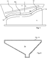
- figure 1 shows a side view of a partial shell 2a, here a half-shell of an air duct component 4 to be produced (see Figures 12,13 ), here of an air outlet component an air conditioning device, not shown, for a passenger cabin of a passenger aircraft.
- the partial shell 2a consists entirely of particle foam of the material EPP and is held or fastened on a receiving tool 6, as a result of which vacuum suction of ambient air is not explained in any more detail.
- the partial shell 2a has a real 3D contour, that is to say it extends not only along one surface but in all three spatial directions.
- the contour or contact surface of the receiving tool 6 is adapted to the partial shell 2a or its 3D contour, so that the partial shell 2a rests at least in sections on the receiving tool 6 and is therefore held securely and firmly on it.
- a heating element 8 is located on the side of the partial shell 2a opposite the receiving tool 6. However, this is spaced apart from the partial shell 2a by an air gap 10.
- the air gap 10 has a constant gap dimension S, here a gap width.
- the heating element 8 is heated homogeneously, ie has the same temperature throughout its volume.
- a heating cartridge 12 is integrated into the heating element 8 for heating.
- the heating element 8 When the heating element 8 is in operation, it radiates heat through the air gap 10 onto the partial shell 2a, so that the latter or the particle foam melts on its surface, i.e. a layer of melt 14 forms on its surface (in the example enlarged and indicated by dashed lines).
- figure 2 shows a top view of the partial shell 2a figure 1 in the direction of arrow Ib. Since the heating element 8 is spaced from the partial shell 2a only in the region of a circumferential contour shown hatched, ie a joining surface 16a, with the gap dimension S and otherwise with a significantly larger gap dimension, the partial shell 2a is only sufficiently heated in the region of the joining surface 16a , in order to melt them and to produce melt 14 there.
- FIG. 1 thus shows process step "E” (heating up one half of the tool) according to FIG. 7.
- Step "I" can now the heated and melted shell part 2a in the region of its joining surface 16a with another Partial shell 2b or its joining surface 16b (likewise melted) can be cohesively connected.
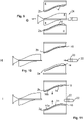
- the Figures 3 to 13 show the process steps AK for producing the air duct component 4 from the partial shells 2a, b or half-shells.
- step A ( figure 3 )
- the partial shells 2a, b are provided and (symbolized by arrows) placed and fastened on respective receiving tools 6, as analogously to figure 1 was explained.
- the partial shells 2a, b have a flattened area 18, not explained in any more detail, in their edge region, which is used for later receiving an attachment 20, here a connecting sleeve.
- the attachment 20 is in step B ( figure 4 ) provided and (symbolized by an arrow) attached to a holder 22 or carrier.
- a heating device 24 is introduced or interposed between the receiving tools 6 or the partial shells 2a, b (symbolized by an arrow).
- the heating device 24 contains an active, i.e. heat-generating, heat source 26 and two heating elements 8 mounted on the heat source 26.
- the heat source 26 is a so-called heating table; the heating elements 18 are passive, here as solid metal blocks, and are only heated by the heat source 26 .
- step D the partial shells 2a,b are lowered towards the heating elements 8 (represented by arrows), so that or until according to step E ( figure 7 ) between each of the partial shells 2a, b and the adjacent heating element 8, a corresponding air gap 10 of the gap size S according to 1 remains.
- step E ( figure 7 ) are heated by thermal radiation from the heating elements 8 across the air gaps 10 away, the partial shells 2a, b on their surfaces in the area of the joint surfaces 16a, b and melted there to melt 14. This is done "contactless”.
- step F conversely to step D, the correspondingly melted partial shells 2a,b are lifted off the heating elements 8 again (represented by arrows) and in step G ( figure 9 ) is reversed to step C, the heater 24 (symbolized by an arrow) removed from the area between the receiving tools 6 and the partial shells 2a, b.
- step H the attachment 20 is introduced using the holder 22 in the direction of the arrow shown between the partial shells 2a, b so far that this, as in step I ( figure 11 ) shown, at a target or mounting position (indicated by dashed lines) between the flattening 18 is located.
- step I figure 11
- the partial shells 2a,b are now also moved towards one another with the aid of the receiving tools 6 in the direction of the arrows until the partial shells 2a,b touch at their joining surfaces 16a,b or the corresponding melts 14 penetrate into one another or become firmly bonded.
- the joining surfaces 16a,b are therefore applied or connected to one another. So there is a contour welding in the area of the joining surfaces 16a, b.
- a form fit (not shown here) is formed between the flat areas 18 and the attachment 20, so that the attachment 20 is fastened between the partial shells 2a, b.
- the attachment 20 is thus embedded between the partial shells 2a, b when they are connected.
- step I the situation shown is maintained until the melts 14 have sufficiently cooled and hardened or solidified or the corresponding material of the partial shells 2a, b has become sufficiently solid.
- a first alternative here is a simple passive waiting for a passive self-cooling of the melts 14.
- the melts 14 or the partial shells 2a, b are actively cooled. The partial shells 2a, b are thus connected to form the component 4 or this is produced.
- step J the receiving tools 6 are then moved away from each other in the direction of the arrows, as a result of which the now completed component 4 is released and corresponding to FIG. K ( figure 13 ) is removed from the receiving tool 6 (indicated by an arrow).
Landscapes
- Engineering & Computer Science (AREA)
- Mechanical Engineering (AREA)
- Physics & Mathematics (AREA)
- Electromagnetism (AREA)
- Health & Medical Sciences (AREA)
- Toxicology (AREA)
- Thermal Sciences (AREA)
- Chemical & Material Sciences (AREA)
- Combustion & Propulsion (AREA)
- Lining Or Joining Of Plastics Or The Like (AREA)
Description
- Die Erfindung betrifft ein Verfahren zum Herstellen eines Luftführungs-Bauteils für eine Klimatisierungsvorrichtung eines Flugzeuges.
- Entsprechende Klimatisierungsvorrichtungen bzw. Klimalösungen dienen insbesondere der Belüftung, Heizung und Kühlung eines Innenraumes eines Flugzeuges, insbesondere einer Passagierkabine in einem Passagierflugzeug. Luft wird hierbei durch die Luftführungs-Bauteile geführt. Beispiele für solche Bauteile sind zum Beispiel Rohre, Verzweigungen, oder Ein- und Auslässe. Die Geometrie derartiger Bauteile kann äußerst komplex sein.
- Aus der Praxis ist es bekannt, derartige Bauteile aus faserverstärkten Kunststoffen, als Sandwichaufbau herzustellen. Geometrisch komplexe Bauteile (wie zum Beispiel Luftauslässe) werden aus mehreren Einzelbauteilen hergestellt, die aufwendig miteinander gefügt werden müssen.
- Die
WO 2016/004522 A1 offenbart ein Verfahren zum Herstellen eines Luftführungs-Bauteils für eine Klimatisierungsvorrichtung eines Flugzeuges, bei dem mehrere Teilschalen mittels eines Infrarotlaserschweißverfahrens miteinander zu einem Bauteil verbunden werden. - Ferner sind aus der
WO 2014/057135 A1 sowie derEP 0 922 559 A1 Verfahren zum Verbinden von Bauteilen bekannt, bei denen Bauteile aus Kunststoffschaum unter Verwendung eines Heizelements kontaktlos erhitzt und verbunden werden. - Aufgabe der Erfindung ist es, ein verbessertes Herstellungsverfahren für ein Luftführungs-Bauteil vorzuschlagen.
- Die Aufgabe wird gelöst durch ein Verfahren gemäß Patentanspruch 1 zum Herstellen eines Luftführungs-Bauteils für eine Klimatisierungsvorrichtung eines Flugzeuges. Bevorzugte oder vorteilhafte Ausführungsformen der Erfindung sowie anderer Erfindungskategorien ergeben sich aus den weiteren Ansprüchen, der nachfolgenden Beschreibung sowie den beigefügten Figuren.
- Bei dem Verfahren werden mindestens zwei Teilschalen des Bauteils bereitgestellt. Mindestens eine der Teilschalen weist eine Fügefläche auf. An dieser Fügefläche ist die Teilschale mit einer anderen der Teilschalen zu verbinden. Die Teilschalen enthalten zumindest an den Fügeflächen Partikelschaum. Mindestens ein Abschnitt einer der Fügeflächen wird kontaktlos erhitzt. Die Teilschalen werden an den erhitzten Fügeflächen aneinander gelegt und dadurch miteinander verbunden.
- Insbesondere werden die Teilschalen dadurch verbunden, dass eine Fügefläche eines ersten Bauteils an eine Fügefläche eines zweiten Bauteils angelegt wird und die Fügeflächen miteinander verbunden werden. Dabei wird mindestens eine der Fügeflächen erhitzt.
- Die Erfindung beruht auf der Idee, derartige Bauteile aus bzw. auf Basis von Partikelschaum zu entwickeln, sodass die Bauteile den Anforderungen der Luftfahrt entsprechen.
- Die Erfindung beruht auf der Beobachtung, dass die besonderen Herausforderungen dabei komplexe 3-D-Geometrien sind, mit engen Maßtoleranzen (aufgrund begrenzten Bauraumes) und hohen Anforderungen an geringes Gewicht sowie eine möglichst weitreichende Integration von weiteren Anbauteilen in oder an den Partikelschaum.
- Die Erfindung beruht auf der Überlegung, dass es hierbei eine Möglichkeit ist, mehrere, Teilschalen, insbesondere zwei Halbschalen, zum eigentlichen Bauteil aneinander zu fügen. Bezüglich des Herstellungsverfahrens wird dabei ein stabiler Prozess sowie reproduzierbare Bauteilqualität gefordert. Die Verbindung der Teilschalen muss dabei mechanisch stabil und luftundurchlässig sein.
- Denkbar wäre es, die Teilschalen durch Kleben bzw. Verwendung von Klebstoff zu fügen; was sich in der Praxis jedoch als schwierig, insbesondere im Hinblick auf brandtechnische Aspekte, darstellt.
- Denkbar wäre auch, die Teilschalen in Hybridbauweise (Schaum und glasfaserverstärkter Kunststoff - GFK) herzustellen und/oder formschlüssig zu fügen.
- Denkbar wäre auch, die Teilschalen mithilfe von Spiegelschweißen auf Kontakt (Erhitzung des Bauteils durch Kontakt mit dem Heizelement) zu verbinden. In der Praxis ergibt sich hierbei jedoch ein zu geringes Temperaturfenster, um eine 3D-Kontur (Fügefläche bzw. Fügelinie), insbesondere mit Höhenversatz, prozesssicher zu verschweißen. Eine weitere Schwierigkeit besteht hierbei in der Schwindung bzw. Schrumpfung des Partikelschaumes bei hohen Temperaturen.
- Durch die Erfindung können komplexe Partikelschaum-Bauteile innerhalb kurzer Prozesszeit stoffschlüssig gefügt werden. Rückstandsloses Schweißen ist möglich, bei einem größeren Prozessfenster als demjenigen, das beim Spiegelschweißen auf Kontakt festgestellt wurde. Dadurch entsteht eine mechanisch beanspruchbare und luftdichte Fügenaht zwischen den Teilschalen ohne den Einsatz von Klebstoffen.
- Generell wird durch die Verwendung von Partikelschaum neben einer Gewichtseinsparung auch eine Verkürzung der Prozesszeiten erreicht, da bisherige Prozessschritte wegfallen. Durch das kontaktlose Erhitzen, insbesondere das kontaktlose Heizelement-schweißen, können komplexe Bauteile aus mehreren Komponenten (Teilschalen) und Einlegern (auch Anbauteile, siehe unten) gefügt werden. Des Weiteren werden mit diesem Material Formgebung und Isolierung des Luftführungs-Bauteils in Einem realisiert.
- Gemäß der Erfindung ergibt sich ein kontaktloses 3-D-Konturverschweißen von Partikelschaum bzw. die Verschweißung von 3D-konturierten Bauteilen in Partikelschaum-Technologie mittels kontaktlosem Heizelement-Schweißen. Luftführende Bauteile in der Luftfahrt können somit (insbesondere aus EPP, Expandiertes Polypropylen) luftdicht und stoffschlüssig gefügt werden.
- Insbesondere wird der Abschnitt so weit erhitzt, dass die Teilschale bzw. der Partikelschaum dort abschmilzt, sich also eine Schmelze bildet, die dann als Verbindungsmittel zur Verbindung mit der oder den anderen Teilschalen dient.
- Insbesondere ergibt sich die Verwendung des kontaktlosen Heizelementschweißens zum Fügen von 3D-kontuerierten (EPP-) Partikelschaumbauteilen für luftführende Bauteile in der Luftfahrt.
- In einer bevorzugten Ausführungsform wird das Verbinden zweier Teilschalen betrachtet; dies gilt jedoch auch für drei oder mehr Teilschalen. An beiden bzw. mindestens zwei bzw. mehreren bzw. allen Teilschalen werden die zu verbindenden Abschnitte der Fügeflächen erhitzt und die erhitzten Abschnitte werden aneinander gelegt und dadurch miteinander verbunden. Insbesondere wird also an beiden Bauteilen eine entsprechende Schmelze gebildet und die beiden Schmelzen miteinander verbunden. So erfolgt eine besonders gute stoffschlüssige Verbindung. Das entsprechende Vorgehen kann auch für drei oder mehr Bauteile genutzt werden, wobei jeweils zwei oder mehr oder sämtliche zu verbindenden Fügeflächen erhitzt werden.
- In einer bevorzugten Ausführungsform werden die zu verbindenden Abschnitte durch Zwischenlage eines Heizelements erhitzt. Das Heizelement wird also zwischen den zu erhitzenden Abschnitten platziert und erhitzt dann die zu verbindenden Abschnitte gleichzeitig. Insbesondere reicht hierzu ein einziges Heizelement aus, welches zum Beispiel an verschiedenen Seiten entsprechende Abschnitte erhitzt. Das Verfahren wird hierdurch vereinfacht.
- Erfindungsgemäß wird der Abschnitt im Rahmen eines kontaktlosen Konturverschweißens durch ein Heizelement kontaktlos erhitzt. Die Erhitzung erfolgt dadurch, dass das Heizelement vom Abschnitt über einen Luftspalt beabstandet ist. So können insbesondere Fügeflächen bzw. Abschnitte in Form von 3D-Konturen kontaktlos erhitzt werden.
- In einer bevorzugten Variante der Erfindung wird beim Erhitzen des Abschnitts ein Luftspalt zwischen Heizelement und Fügefläche benutzt, der ein konstantes Spaltmaß aufweist. Das Heizelement ist also vom zu erhitzenden Abschnitt jeweils konstant beabstandet. So kann eine gleichmäßige Erhitzung des Abschnitts erreicht werden.
- Erfindungsgemäß wird als Heizelement ein passives Heizelement verwendet, das durch eine aktive Wärmequelle beheizt wird. Das passive Heizelement ist insbesondere ein Heizaufsatz. So können insbesondere verschiedene Heizelemente an verschiedene Konturen zu erhitzender Abschnitte angeglichen werden und durch Austausch der Heizelemente mit der gleichen Wärmequelle genutzt werden, um verschiedene Abschnitte zu erhitzen.
- Erfindungsgemäß wird als aktive Wärmequelle ein Heiztisch verwendet, der mindestens einseitig ein Heizelement trägt. Insbesondere sind beidseitig Heizelemente angeordnet; verschiedene und insbesondere voneinander abgewandte Oberflächen dienen dann dem Erhitzen unterschiedlicher Abschnitte. Luftspalte werden dann insbesondere jeweils zum entsprechenden Abschnitt hin eingestellt.
- In einer bevorzugten Ausführungsform wird mindestens eine der Teilschalen mindestens zum Erhitzen und/oder zum Verbinden auf einem Aufnahmewerkzeug gehalten. Die Teilschale wird insbesondere durch Unterdruck und/oder durch eine mechanische Haltevorrichtung auf dem Aufnahmewerkzeug gehalten. So können die Teilschalen leicht mithilfe der Aufnahmewerkzeuge gehalten und/oder relativ zueinander bewegt werden.
- In einer bevorzugten Ausführungsform weist das Luftführungsbauteil mindestens ein Anbauteil auf. Bei dem Verfahren wird zusätzlich zu den Teilschalen das Anbauteil bereitgestellt. Das Anbauteil wird mit den Teilschalen verbunden, indem es beim Verbinden der Teilschalen zwischen diesen eingebettet wird. Optional kann am Verbindungsort mit der Teilschale eine Fügefläche vorgesehen sein, die dann mit dem Anbauteil verbunden wird. Insbesondere wird das Anbauteil dadurch mit mindestens zwei der Teilschalen verbunden, dass mindestens zwei der Teilschalen unter Zwischenlage des Anbauteils miteinander verbunden werden. Derartige Anbauteile werden auch als Einleger bezeichnet.
- In einer bevorzugten Variante dieser Ausführungsform wird das Anbauteil mit mindestens einer der Teilschalen, insbesondere allen beteiligten Teilschalen, stoff- und/oder formschlüssig verbunden. So entsteht ein besonders guter mechanischer Halt des Anbauteils im Bauteil. Hierzu ist insbesondere im Bereich des Anbauteils eine Fügefläche vorgesehen, die dann vor der Verbindung mit dem Anbauteil erhitzt, insbesondere aufgeschmolzen, wird.
- In einer bevorzugten Ausführungsform wird mindestens eine Teilschale bereitgestellt, deren Fügefläche nicht vollständig in einer Ebene verläuft. Die Fügefläche weist also Erstreckungskomponenten in allen 3 Raumrichtungen auf, ist also nicht "flächig", es handelt sich um eine "echte" 3D-Geometrie. Besonders für derartige Fügeflächen eignet sich das vorliegende Verfahren.
- In einer bevorzugten Ausführungsform wird mindestens eine der Teilschalen als Partikelschaumteil bereitgestellt. Die entsprechende Teilschale ist also insbesondere aus Partikelschaum gebildet. Dabei kann die Teilschale insbesondere vollständig aus Partikelschaum bestehen. Alternativ besteht diese aus Partikelschaum als Grundmaterial, wobei noch andere Komponenten enthalten sind, z.B. Einlegestrukturen, bereits angebrachte Anbauteile etc.
- In einer bevorzugten Ausführungsform wird mindestens eine der Teilschalen bereitgestellt, bei der der Partikelschaum EPP (Expandiertes Polypropylen) ist. Der entsprechende Werkstoff eignet sich besonders für das vorliegende Verfahren.
- In einer bevorzugten Ausführungsform werden genau zwei Teilschalen bereitgestellt. Die Teilschalen sind dann insbesondere Halbschalen. So können Bauteile besonders einfach aus nur zwei Teilen gefertigt werden.
- In einer bevorzugten Ausführungsform wird als Bauteil ein Luftauslassbauteil hergestellt. Gerade diese Bauteile weisen oft eine besonders komplexe 3D-Geometrie auf und eignen sich daher besonders zur Herstellung durch das vorliegende Verfahren. Insbesondere ist das Bauteil ein Single Aisle, Ceiling Air Outlet oder ein Single Aisle, Lateral Air Outlet.
- Weitere Merkmale, Wirkungen und Vorteile der Erfindung ergeben sich aus der nachfolgenden Beschreibung eines bevorzugten Ausführungsbeispiels der Erfindung sowie der beigefügten Figuren. Dabei zeigen, jeweils in einer schematischen Prinzipskizze:
- Figur 1
- eine Teilschale beim Erhitzen der Fügefläche in Seitenansicht,
- Figur 2
- eine Teilschale beim Erhitzen der Fügefläche in Draufsicht,
- Figuren 3 bis 13
- Verfahrensschritte A bis K beim Herstellen eines Luftführung-Bauteils.
-
Figur 1 zeigt in Seitenansicht eine Teilschale 2a, hier eine Halbschale eines herzustellenden Luftführungs-Bauteils 4 (sieheFiguren 12,13 ), hier eines Luftauslass-Bauteils einer nicht näher dargestellten Klimatisierungsvorrichtung für eine Passagierkabine eines Passagierflugzeuges. Die Teilschale 2a besteht vollständig aus Partikelschaum des Materials EPP und ist auf einem Aufnahmewerkzeug 6 gehalten bzw. befestigt, hierdurch nicht näher erläuterte Unterdruck-Ansaugung von Umgebungsluft. Die Teilschale 2a weist eine echte 3D-Kontur auf, das heißt sie erstreckt sich nicht nur entlang einer Fläche, sondern in alle drei Raumrichtungen. Das Aufnahmewerkzeug 6 ist bezüglich seiner Kontur bzw. Auflagefläche an die Teilschale 2a bzw. deren 3D-Kontur angepasst, sodass die Teilschale 2a zumindest abschnittsweise am Aufnahmewerkzeug 6 aufliegt und daher sicher und fest auf diesem gehalten ist. - Auf der dem Aufnahmewerkzeug 6 gegenüberliegenden Seite der Teilschale 2a befindet sich ein Heizelement 8. Dieses ist jedoch von der Teilschale 2a durch einen Luftspalt 10 beabstandet. Hier weist der Luftspalt 10 ein konstantes Spaltmaß S, hier eine Spaltbreite auf.
- Im Beispiel ist das Heizelement 8 homogen erhitzt, weist also in seinem gesamten Volumen gleiche Temperatur auf. Zur Beheizung ist eine Heizpatrone 12 in das Heizelement 8 integriert.
- Beim Betrieb des Heizelements 8 strahlt dieses über den Luftspalt 10 Wärme auf die Teilschale 2a ab, sodass diese bzw. der Partikelschaum an deren Oberfläche aufschmilzt, d.h. sich eine Schicht Schmelze 14 an deren Oberfläche bildet (im Beispiel vergrößert und gestrichelt angedeutet).
-
Figur 2 zeigt eine Draufsicht auf die Teilschale 2a ausFigur 1 in Richtung des Pfeils Ib. Da das Heizelement 8 nur im Bereich einer schraffiert dargestellten, umlaufenden Kontur, d.h. einer Fügefläche 16a, mit dem Spaltmaß S und ansonsten mit einem deutlich größeren Spaltmaß von der Teilschale 2a beabstandet ist, erfolgt nur im Bereich der Fügefläche 16a eine ausreichende Erwärmung der Teilschale 2a, um diese aufzuschmelzen und dort Schmelze 14 zu erzeugen. -
Figur 1 zeigt damit den Prozessschritt "E" (Aufheizen einer Werkzeughälfte) gemäß Figur 7. In einem nachfolgenden Schritt (sieheFigur 11 Schritt "I") kann nun die erhitzte und aufgeschmolzene Teilschale 2a im Bereich ihrer Fügefläche 16a mit einer weiteren Teilschale 2b bzw. deren Fügefläche 16b (ebenfalls aufgeschmolzen) stoffschlüssig verbunden werden. - Die
Figuren 3 bis 13 zeigen die Prozessschritte A-K zum Herstellen des Luftführungs-Bauteils 4 aus den Teilschalen 2a,b bzw. Halbschalen. - Im Schritt A (
Figur 3 ) werden die Teilschalen 2a,b bereitgestellt und (durch Pfeile symbolisiert) auf jeweiligen Aufnahmewerkzeugen 6 aufgelegt und befestigt, wie sinngemäß zuFigur 1 erläutert wurde. In Abwandlung zuFigur 1 weisen die Teilschalen 2a,b in ihrem Randbereich eine nicht näher erläuterte Abflachung 18 auf, die zur späteren Aufnahme eines Anbauteils 20, hier einer Anschlussmuffe, dient. - Das Anbauteil 20 wird in Schritt B (
Figur 4 ) bereitgestellt und (durch Pfeil symbolisiert) auf einem Halter 22 bzw. Träger befestigt. - In Schritt C (
Figur 5 ) wird eine Heizvorrichtung 24 zwischen die Aufnahmewerkzeuge 6 bzw. die Teilschalen 2a,b eingebracht bzw. zwischengelegt (durch Pfeil symbolisiert). Die Heizvorrichtung 24 enthält eine aktive, d.h. wärmeerzeugende Wärmequelle 26 sowie zwei, auf der Wärmequelle 26 montierte Heizelemente 8. Die Wärmequelle 26 ist ein sogenannter Heiztisch, die Heizelemente 18 sind passiv ausgeführt, hier als massive Metallblöcke, und werden einzig durch die Wärmequelle 26 erwärmt. - In Schritt D (
Figur 6 ) werden die Teilschalen 2a,b zu den Heizelementen 8 hin abgesenkt (durch Pfeile dargestellt), so dass bzw. bis gemäß Schritt E (Figur 7 ) zwischen je einer der Teilschalen 2a,b und dem benachbarten Heizelement 8 ein entsprechender Luftspalt 10 des Spaltmaßes S gemäßFig. 1 verbleibt. - In Schritt E (
Figur 7 ) werden durch Wärmestrahlung von den Heizelementen 8 über die Luftspalte 10 hinweg die Teilschalen 2a,b an deren Oberflächen im Bereich der Fügeflächen 16a,b erhitzt und dort zu Schmelze 14 aufgeschmolzen. Dies geschieht also "kontaktlos". - In Schritt F (
Figur 8 ) werden umgekehrt zu Schritt D die entsprechend aufgeschmolzenen Teilschalen 2a,b von den Heizelementen 8 wieder abgehoben (durch Pfeile dargestellt) und in Schritt G (Figur 9 ) wird umgekehrt zu Schritt C die Heizvorrichtung 24 (durch Pfeil symbolisiert) wieder aus dem Bereich zwischen den Aufnahmewerkzeugen 6 bzw. den Teilschalen 2a,b entfernt. - In Schritt H (
Figur 10 ) wird das Anbauteil 20 mithilfe des Halters 22 in Richtung des dargestellten Pfeils so weit zwischen die Teilschalen 2a,b eingebracht, dass sich dieses, wie in Schritt I (Figur 11 ) dargestellt, an einer Soll- bzw. Montageposition (durch gestrichelte Linien angedeutet) zwischen den Abflachung 18 befindet. In Schritt I (Figur 11 ) werden nun außerdem die Teilschalen 2a,b mit Hilfe der Aufnahmewerkzeuge 6 in Richtung der Pfeile aufeinander zu bewegt, bis sich die Teilschalen 2a,b an ihren Fügeflächen 16a,b berühren bzw. die entsprechenden Schmelzen 14 ineinander eindringen bzw. sich stoffschlüssig verbinden. Die Fügeflächen 16a,b werden also aneinander angelegt bzw. verbunden. Es erfolgt also ein Konturverschweißen im Bereich der Fügeflächen 16a,b. Dabei wird außerdem zwischen den Abflachungen 18 und dem Anbauteil 20 ein (hier nicht dargestellter) Formschluss gebildet, sodass das Anbauteil 20 zwischen den Teilschalen 2a,b befestigt ist. Das Anbauteil 20 wird also zwischen den Teilschalen 2a,b bei deren Verbinden eingebettet. - In Schritt I wird die dargestellte Situation dabei so lange gehalten, bis die Schmelzen 14 ausreichend abgekühlt und ausgehärtet bzw. erstarrt sind bzw. das entsprechende Material der Teilschalen 2a,b ausreichend fest geworden ist. Eine erste Alternative ist hierbei ein einfaches passives Abwarten einer passiven Selbstabkühlung der Schmelzen 14. In einer zweiten Alternative werden die Schmelzen 14 bzw. die Teilschalen 2a,b aktiv abgekühlt. Damit sind die Teilschalen 2a,b zum Bauteil 4 verbunden bzw. ist dieses hergestellt.
- Gemäß Schritt J (
Figur 12 ) werden anschließend die Aufnahmewerkzeuge 6 in Richtung der Pfeile voneinander wegbewegt, wodurch das nun fertig gestellte Bauteil 4 freigegeben wird und entsprechend Figur K (Figur 13 ) vom Aufnahmewerkzeug 6 entnommen wird (angedeutet durch einen Pfeil). -
- 2a,b
- Teilschale
- 4
- Luftführung-Bauteil
- 6
- Aufnahmewerkzeug
- 8
- Heizelement
- 10
- Luftspalt
- 12
- Heizpatrone
- 14
- Schmelze
- 16a,b
- Fügefläche
- 18
- Abflachung
- 20
- Anbauteil
- 22
- Halter
- 24
- Heizvorrichtung
- 26
- Wärmequelle
- S
- Spaltmaß
- A-K
- Prozess Schritt
Claims (12)
- Verfahren zum Herstellen eines Luftführungs-Bauteils (4) für eine Klimatisierungsvorrichtung eines Flugzeuges, bei dem:- mindestens zwei Teilschalen (2a,b) des Bauteils (4) bereitgestellt werden, wobei mindestens eine der Teilschalen (2a,b) eine Fügefläche (16a,b) aufweist, an der sie mit einer anderen der Teilschalen (2a,b) zu verbinden ist, und die Teilschalen (2a,b) zumindest an den Fügeflächen (16a,b) Partikelschaum enthalten,- mindestens ein Abschnitt einer der Fügeflächen (16a,b) kontaktlos erhitzt wird,- die Teilschalen (2a,b) an den erhitzten Fügeflächen (16a,b) aneinander gelegt und dadurch miteinander zum Bauteil (4) verbunden werden,dadurch gekennzeichnet, dassder Abschnitt im Rahmen eines kontaktlosen Konturverschweißens durch ein über einen Luftspalt (10) beabstandetes Heizelement (8) kontaktlos erhitzt wird,als Heizelement (8) ein passives Heizelement (8) verwendet wird, das durch eine aktive Wärmequelle (26) beheizt wird,als aktive Wärmequelle (26) ein Heiztisch verwendet wird, der mindestens einseitig ein Heizelement (8) trägt.
- Verfahren nach Anspruch 1,
dadurch gekennzeichnet, dass
für das Verbinden zweier Teilschalen (2a,b) an beiden Teilschalen (2a,b) die zu verbindenden Abschnitte der Fügeflächen (16a,b) erhitzt werden und die erhitzten Abschnitte aneinander gelegt und dadurch miteinander verbunden werden. - Verfahren nach einem der vorhergehenden Ansprüche,
dadurch gekennzeichnet, dass
die zu verbindenden Abschnitte durch Zwischenlage des Heizelements (8) erhitzt werden. - Verfahren nach einem der vorhergehenden Ansprüche,
dadurch gekennzeichnet, dass
beim Erhitzen des Abschnitts ein Luftspalt (10) zwischen Heizelement (8) und Fügefläche benutzt wird, der ein konstantes Spaltmaß (S) aufweist. - Verfahren nach einem der vorhergehenden Ansprüche,
dadurch gekennzeichnet, dass
mindestens eine der Teilschalen (2a,b) mindestens zum Erhitzen und/oder zum Verbinden auf einem Aufnahmewerkzeug (6) gehalten wird. - Verfahren nach einem der vorhergehenden Ansprüche,
dadurch gekennzeichnet, dass
das Luftführungs-Bauteil (4) mindestens ein Anbauteil (20) aufweist, wobei- zusätzlich zu den Teilschalen (2a,b) das Anbauteil (20) bereitgestellt wird,- das Anbauteil (20) mit den Teilschalen (2a,b) verbunden wird, indem es beim Verbinden der Teilschalen (2a,b) zwischen diesen eingebettet wird, - Verfahren nach Anspruch6,
dadurch gekennzeichnet, dass
das Anbauteil (20) mit mindestens einer der Teilschalen (2a,b) stoff- und/oder formschlüssig verbunden wird. - Verfahren nach einem der vorhergehenden Ansprüche,
dadurch gekennzeichnet, dass
mindestens eine Teilschale (2a,b) bereitgestellt wird, deren Fügefläche (16a,b) nicht vollständig in einer Ebene verläuft. - Verfahren nach einem der vorhergehenden Ansprüche,
dadurch gekennzeichnet, dass
mindestens eine der Teilschalen (2a,b) als Partikelschaumteil bereitgestellt wird. - Verfahren nach einem der vorhergehenden Ansprüche,
dadurch gekennzeichnet, dass
mindestens eine der Teilschalen (2a,b) bereitgestellt wird, bei der der Partikelschaum EPP ist. - Verfahren nach einem der vorhergehenden Ansprüche, dadurch gekennzeichnet, dass
genau zwei Teilschalen (2a,b) bereitgestellt werden. - Verfahren nach einem der vorhergehenden Ansprüche, dadurch gekennzeichnet, dass
als Bauteil (4) ein Luftauslassbauteil hergestellt wird.
Applications Claiming Priority (2)
| Application Number | Priority Date | Filing Date | Title |
|---|---|---|---|
| DE102019002129 | 2019-03-26 | ||
| PCT/EP2020/058100 WO2020193518A1 (de) | 2019-03-26 | 2020-03-24 | Verfahren zum herstellen eines luftführungs-bauteils |
Publications (2)
| Publication Number | Publication Date |
|---|---|
| EP3917759A1 EP3917759A1 (de) | 2021-12-08 |
| EP3917759B1 true EP3917759B1 (de) | 2022-07-13 |
Family
ID=69960646
Family Applications (1)
| Application Number | Title | Priority Date | Filing Date |
|---|---|---|---|
| EP20713883.5A Active EP3917759B1 (de) | 2019-03-26 | 2020-03-24 | Verfahren zum herstellen eines luftführungs-bauteils |
Country Status (2)
| Country | Link |
|---|---|
| EP (1) | EP3917759B1 (de) |
| WO (1) | WO2020193518A1 (de) |
Family Cites Families (3)
| Publication number | Priority date | Publication date | Assignee | Title |
|---|---|---|---|---|
| DE19754834A1 (de) * | 1997-12-10 | 1999-06-17 | Volkswagen Ag | Verfahren zum Verbinden von Bauteilen |
| DE102012218655B4 (de) * | 2012-10-12 | 2019-11-28 | Iwi Gmbh | Vorrichtung und Verfahren zum dauerhaften Verbinden zweier Kunststoffschaumelemente |
| CA2916612A1 (en) * | 2014-07-11 | 2016-01-11 | Exo-S Inc. | A light-weight air duct for ventilation, air conditioning and heating for use in a vehicle and a method of manufacturing same |
-
2020
- 2020-03-24 WO PCT/EP2020/058100 patent/WO2020193518A1/de not_active Ceased
- 2020-03-24 EP EP20713883.5A patent/EP3917759B1/de active Active
Also Published As
| Publication number | Publication date |
|---|---|
| EP3917759A1 (de) | 2021-12-08 |
| WO2020193518A1 (de) | 2020-10-01 |
Similar Documents
| Publication | Publication Date | Title |
|---|---|---|
| DE102016210086B4 (de) | Verfahren zum Herstellen eines Strukturbauteils für ein Luft- oder Raumfahrzeug, sowie Anordnung | |
| DE102009059720B4 (de) | Vorrichtung zur Herstellung einer aus Faserverbundwerkstoff bestehenden Rumpfschale für ein Luftfahrzeug | |
| EP3040182B1 (de) | Verfahren zur herstellung eines strukturbauteils, halbzeug, verfahren zur herstellung eines halbzeugs, strukturbauteil, sowie luft- oder raumfahrzeug | |
| DE102016210124B4 (de) | Verfahren zur Integration einer Hinterbaustruktur-Baugruppe in eine Struktur eines Luft- oder Raumfahrzeugs | |
| DE102011085937B4 (de) | Leichtbaustruktur, insbesondere Flugzeugprimärstruktur oder untergeordnete Baugruppe, sowie Verfahren zu deren Herstellung | |
| DE102009060689B4 (de) | Verfahren zur Herstellung eines faserverstärkten Bauteils sowie Vorrichtung zur Durchführung des Verfahrens | |
| DE102009056580A1 (de) | Verfahren und Vorrichtung zum Verbinden von thermoplastischen Faserverbundbauteilen mittels stiftförmiger Funktionselemente | |
| DE102012008369A1 (de) | Verfahren zum Herstellen eines fluidführenden Bauteils durch schichtweisen Aufbau | |
| DE102014215935A1 (de) | Vorrichtung und Verfahren zur Fertigung von Bauteilen aus einem faserverstärkten Verbundmaterial | |
| DE112012007279T5 (de) | Fahrzeuginnenplatte und Verfahren zum Herstellen derselben | |
| DE102011100702B4 (de) | Verfahren zur Herstellung eines Verbundbauteils unter Verwendung einer zuvor bearbeiteten Wabenstruktur | |
| DE102011114924A1 (de) | Bewegbare Fügeeinrichtung zum Verbinden von Strukturbauteilen eines Luftfahrzeuges | |
| DE102015013915A1 (de) | Maschinensystem zur Herstellung eines Hybridbauteils | |
| DE102012021763A1 (de) | Spannvorrichtung zum Positionieren und Haltern von flächigen Werkstücken mittels Metallsteifen für ein flächiges und direktes Aufbringen der Spannkraft | |
| EP1658148B1 (de) | Verfahren zum umformen von blechen | |
| EP2578347A2 (de) | Fügevorrichtung zum Verbinden von Strukturbauteilen eines Luftfahrzeuges | |
| DE102009023864B4 (de) | Vorrichtung und Verfahren zur Herstellung eines Dopplers | |
| DE102013016685B3 (de) | Werkzeugform für ein Kaschier- oder Urformwerkzeug | |
| DE102016203711A1 (de) | Verfahren zur Herstellung eines formstabilen Hohlkörpers sowie Hohlkörper, hergestellt nach besagtem Verfahren | |
| EP3917759A1 (de) | Verfahren zum herstellen eines luftführungs-bauteils | |
| EP4197736B1 (de) | Formwerkzeug zur herstellung eines partikelschaumformteils | |
| DE102017102881A1 (de) | Verfahren für die Herstellung eines Mehrkomponentenbauteils eines Fahrzeugs | |
| DE102023113507A1 (de) | Konsolidierungseinrichtung und Vorrichtung zum kontinuierlichen Ultraschallschweißen | |
| DE102004062896A1 (de) | Vorrichtung und Verfahren zum formschlüssigen Verbinden von Werkstücken | |
| EP3260277B1 (de) | Verfahren und vorrichtung zum thermischen fügen einer schicht aus einem kunststoffmaterial auf einem kunststoffrohr |
Legal Events
| Date | Code | Title | Description |
|---|---|---|---|
| STAA | Information on the status of an ep patent application or granted ep patent |
Free format text: STATUS: UNKNOWN |
|
| STAA | Information on the status of an ep patent application or granted ep patent |
Free format text: STATUS: THE INTERNATIONAL PUBLICATION HAS BEEN MADE |
|
| PUAI | Public reference made under article 153(3) epc to a published international application that has entered the european phase |
Free format text: ORIGINAL CODE: 0009012 |
|
| STAA | Information on the status of an ep patent application or granted ep patent |
Free format text: STATUS: REQUEST FOR EXAMINATION WAS MADE |
|
| 17P | Request for examination filed |
Effective date: 20210902 |
|
| AK | Designated contracting states |
Kind code of ref document: A1 Designated state(s): AL AT BE BG CH CY CZ DE DK EE ES FI FR GB GR HR HU IE IS IT LI LT LU LV MC MK MT NL NO PL PT RO RS SE SI SK SM TR |
|
| GRAP | Despatch of communication of intention to grant a patent |
Free format text: ORIGINAL CODE: EPIDOSNIGR1 |
|
| STAA | Information on the status of an ep patent application or granted ep patent |
Free format text: STATUS: GRANT OF PATENT IS INTENDED |
|
| RIC1 | Information provided on ipc code assigned before grant |
Ipc: B29L 31/30 20060101ALN20220303BHEP Ipc: B64D 13/00 20060101ALN20220303BHEP Ipc: B29C 65/24 20060101ALI20220303BHEP Ipc: B29C 65/78 20060101ALI20220303BHEP Ipc: B29C 65/10 20060101ALI20220303BHEP Ipc: B29C 65/14 20060101AFI20220303BHEP |
|
| DAV | Request for validation of the european patent (deleted) | ||
| DAX | Request for extension of the european patent (deleted) | ||
| INTG | Intention to grant announced |
Effective date: 20220404 |
|
| GRAS | Grant fee paid |
Free format text: ORIGINAL CODE: EPIDOSNIGR3 |
|
| GRAA | (expected) grant |
Free format text: ORIGINAL CODE: 0009210 |
|
| STAA | Information on the status of an ep patent application or granted ep patent |
Free format text: STATUS: THE PATENT HAS BEEN GRANTED |
|
| AK | Designated contracting states |
Kind code of ref document: B1 Designated state(s): AL AT BE BG CH CY CZ DE DK EE ES FI FR GB GR HR HU IE IS IT LI LT LU LV MC MK MT NL NO PL PT RO RS SE SI SK SM TR |
|
| REG | Reference to a national code |
Ref country code: CH Ref legal event code: EP |
|
| REG | Reference to a national code |
Ref country code: DE Ref legal event code: R096 Ref document number: 502020001372 Country of ref document: DE |
|
| REG | Reference to a national code |
Ref country code: AT Ref legal event code: REF Ref document number: 1504056 Country of ref document: AT Kind code of ref document: T Effective date: 20220815 |
|
| REG | Reference to a national code |
Ref country code: IE Ref legal event code: FG4D Free format text: LANGUAGE OF EP DOCUMENT: GERMAN |
|
| REG | Reference to a national code |
Ref country code: LT Ref legal event code: MG9D |
|
| REG | Reference to a national code |
Ref country code: NL Ref legal event code: MP Effective date: 20220713 |
|
| PG25 | Lapsed in a contracting state [announced via postgrant information from national office to epo] |
Ref country code: SE Free format text: LAPSE BECAUSE OF FAILURE TO SUBMIT A TRANSLATION OF THE DESCRIPTION OR TO PAY THE FEE WITHIN THE PRESCRIBED TIME-LIMIT Effective date: 20220713 Ref country code: RS Free format text: LAPSE BECAUSE OF FAILURE TO SUBMIT A TRANSLATION OF THE DESCRIPTION OR TO PAY THE FEE WITHIN THE PRESCRIBED TIME-LIMIT Effective date: 20220713 Ref country code: PT Free format text: LAPSE BECAUSE OF FAILURE TO SUBMIT A TRANSLATION OF THE DESCRIPTION OR TO PAY THE FEE WITHIN THE PRESCRIBED TIME-LIMIT Effective date: 20221114 Ref country code: NO Free format text: LAPSE BECAUSE OF FAILURE TO SUBMIT A TRANSLATION OF THE DESCRIPTION OR TO PAY THE FEE WITHIN THE PRESCRIBED TIME-LIMIT Effective date: 20221013 Ref country code: NL Free format text: LAPSE BECAUSE OF FAILURE TO SUBMIT A TRANSLATION OF THE DESCRIPTION OR TO PAY THE FEE WITHIN THE PRESCRIBED TIME-LIMIT Effective date: 20220713 Ref country code: LV Free format text: LAPSE BECAUSE OF FAILURE TO SUBMIT A TRANSLATION OF THE DESCRIPTION OR TO PAY THE FEE WITHIN THE PRESCRIBED TIME-LIMIT Effective date: 20220713 Ref country code: LT Free format text: LAPSE BECAUSE OF FAILURE TO SUBMIT A TRANSLATION OF THE DESCRIPTION OR TO PAY THE FEE WITHIN THE PRESCRIBED TIME-LIMIT Effective date: 20220713 Ref country code: FI Free format text: LAPSE BECAUSE OF FAILURE TO SUBMIT A TRANSLATION OF THE DESCRIPTION OR TO PAY THE FEE WITHIN THE PRESCRIBED TIME-LIMIT Effective date: 20220713 Ref country code: ES Free format text: LAPSE BECAUSE OF FAILURE TO SUBMIT A TRANSLATION OF THE DESCRIPTION OR TO PAY THE FEE WITHIN THE PRESCRIBED TIME-LIMIT Effective date: 20220713 |
|
| PG25 | Lapsed in a contracting state [announced via postgrant information from national office to epo] |
Ref country code: PL Free format text: LAPSE BECAUSE OF FAILURE TO SUBMIT A TRANSLATION OF THE DESCRIPTION OR TO PAY THE FEE WITHIN THE PRESCRIBED TIME-LIMIT Effective date: 20220713 Ref country code: IS Free format text: LAPSE BECAUSE OF FAILURE TO SUBMIT A TRANSLATION OF THE DESCRIPTION OR TO PAY THE FEE WITHIN THE PRESCRIBED TIME-LIMIT Effective date: 20221113 Ref country code: HR Free format text: LAPSE BECAUSE OF FAILURE TO SUBMIT A TRANSLATION OF THE DESCRIPTION OR TO PAY THE FEE WITHIN THE PRESCRIBED TIME-LIMIT Effective date: 20220713 Ref country code: GR Free format text: LAPSE BECAUSE OF FAILURE TO SUBMIT A TRANSLATION OF THE DESCRIPTION OR TO PAY THE FEE WITHIN THE PRESCRIBED TIME-LIMIT Effective date: 20221014 |
|
| REG | Reference to a national code |
Ref country code: DE Ref legal event code: R097 Ref document number: 502020001372 Country of ref document: DE |
|
| PG25 | Lapsed in a contracting state [announced via postgrant information from national office to epo] |
Ref country code: SM Free format text: LAPSE BECAUSE OF FAILURE TO SUBMIT A TRANSLATION OF THE DESCRIPTION OR TO PAY THE FEE WITHIN THE PRESCRIBED TIME-LIMIT Effective date: 20220713 Ref country code: RO Free format text: LAPSE BECAUSE OF FAILURE TO SUBMIT A TRANSLATION OF THE DESCRIPTION OR TO PAY THE FEE WITHIN THE PRESCRIBED TIME-LIMIT Effective date: 20220713 Ref country code: DK Free format text: LAPSE BECAUSE OF FAILURE TO SUBMIT A TRANSLATION OF THE DESCRIPTION OR TO PAY THE FEE WITHIN THE PRESCRIBED TIME-LIMIT Effective date: 20220713 Ref country code: CZ Free format text: LAPSE BECAUSE OF FAILURE TO SUBMIT A TRANSLATION OF THE DESCRIPTION OR TO PAY THE FEE WITHIN THE PRESCRIBED TIME-LIMIT Effective date: 20220713 |
|
| PLBE | No opposition filed within time limit |
Free format text: ORIGINAL CODE: 0009261 |
|
| STAA | Information on the status of an ep patent application or granted ep patent |
Free format text: STATUS: NO OPPOSITION FILED WITHIN TIME LIMIT |
|
| PG25 | Lapsed in a contracting state [announced via postgrant information from national office to epo] |
Ref country code: SK Free format text: LAPSE BECAUSE OF FAILURE TO SUBMIT A TRANSLATION OF THE DESCRIPTION OR TO PAY THE FEE WITHIN THE PRESCRIBED TIME-LIMIT Effective date: 20220713 Ref country code: EE Free format text: LAPSE BECAUSE OF FAILURE TO SUBMIT A TRANSLATION OF THE DESCRIPTION OR TO PAY THE FEE WITHIN THE PRESCRIBED TIME-LIMIT Effective date: 20220713 |
|
| 26N | No opposition filed |
Effective date: 20230414 |
|
| PG25 | Lapsed in a contracting state [announced via postgrant information from national office to epo] |
Ref country code: AL Free format text: LAPSE BECAUSE OF FAILURE TO SUBMIT A TRANSLATION OF THE DESCRIPTION OR TO PAY THE FEE WITHIN THE PRESCRIBED TIME-LIMIT Effective date: 20220713 |
|
| PG25 | Lapsed in a contracting state [announced via postgrant information from national office to epo] |
Ref country code: MC Free format text: LAPSE BECAUSE OF FAILURE TO SUBMIT A TRANSLATION OF THE DESCRIPTION OR TO PAY THE FEE WITHIN THE PRESCRIBED TIME-LIMIT Effective date: 20220713 |
|
| REG | Reference to a national code |
Ref country code: CH Ref legal event code: PL |
|
| REG | Reference to a national code |
Ref country code: BE Ref legal event code: MM Effective date: 20230331 |
|
| PG25 | Lapsed in a contracting state [announced via postgrant information from national office to epo] |
Ref country code: LU Free format text: LAPSE BECAUSE OF NON-PAYMENT OF DUE FEES Effective date: 20230324 |
|
| REG | Reference to a national code |
Ref country code: IE Ref legal event code: MM4A |
|
| PG25 | Lapsed in a contracting state [announced via postgrant information from national office to epo] |
Ref country code: LI Free format text: LAPSE BECAUSE OF NON-PAYMENT OF DUE FEES Effective date: 20230331 Ref country code: IT Free format text: LAPSE BECAUSE OF FAILURE TO SUBMIT A TRANSLATION OF THE DESCRIPTION OR TO PAY THE FEE WITHIN THE PRESCRIBED TIME-LIMIT Effective date: 20220713 Ref country code: IE Free format text: LAPSE BECAUSE OF NON-PAYMENT OF DUE FEES Effective date: 20230324 Ref country code: CH Free format text: LAPSE BECAUSE OF NON-PAYMENT OF DUE FEES Effective date: 20230331 |
|
| PG25 | Lapsed in a contracting state [announced via postgrant information from national office to epo] |
Ref country code: BE Free format text: LAPSE BECAUSE OF NON-PAYMENT OF DUE FEES Effective date: 20230331 |
|
| PG25 | Lapsed in a contracting state [announced via postgrant information from national office to epo] |
Ref country code: BG Free format text: LAPSE BECAUSE OF FAILURE TO SUBMIT A TRANSLATION OF THE DESCRIPTION OR TO PAY THE FEE WITHIN THE PRESCRIBED TIME-LIMIT Effective date: 20220713 |
|
| GBPC | Gb: european patent ceased through non-payment of renewal fee |
Effective date: 20240324 |
|
| PG25 | Lapsed in a contracting state [announced via postgrant information from national office to epo] |
Ref country code: BG Free format text: LAPSE BECAUSE OF FAILURE TO SUBMIT A TRANSLATION OF THE DESCRIPTION OR TO PAY THE FEE WITHIN THE PRESCRIBED TIME-LIMIT Effective date: 20220713 |
|
| PG25 | Lapsed in a contracting state [announced via postgrant information from national office to epo] |
Ref country code: GB Free format text: LAPSE BECAUSE OF NON-PAYMENT OF DUE FEES Effective date: 20240324 |
|
| PG25 | Lapsed in a contracting state [announced via postgrant information from national office to epo] |
Ref country code: GB Free format text: LAPSE BECAUSE OF NON-PAYMENT OF DUE FEES Effective date: 20240324 |
|
| PGFP | Annual fee paid to national office [announced via postgrant information from national office to epo] |
Ref country code: AT Payment date: 20250417 Year of fee payment: 5 |
|
| PGFP | Annual fee paid to national office [announced via postgrant information from national office to epo] |
Ref country code: DE Payment date: 20250515 Year of fee payment: 6 |
|
| PG25 | Lapsed in a contracting state [announced via postgrant information from national office to epo] |
Ref country code: CY Free format text: LAPSE BECAUSE OF FAILURE TO SUBMIT A TRANSLATION OF THE DESCRIPTION OR TO PAY THE FEE WITHIN THE PRESCRIBED TIME-LIMIT; INVALID AB INITIO Effective date: 20200324 |
|
| PG25 | Lapsed in a contracting state [announced via postgrant information from national office to epo] |
Ref country code: HU Free format text: LAPSE BECAUSE OF FAILURE TO SUBMIT A TRANSLATION OF THE DESCRIPTION OR TO PAY THE FEE WITHIN THE PRESCRIBED TIME-LIMIT; INVALID AB INITIO Effective date: 20200324 |
|
| PG25 | Lapsed in a contracting state [announced via postgrant information from national office to epo] |
Ref country code: TR Free format text: LAPSE BECAUSE OF FAILURE TO SUBMIT A TRANSLATION OF THE DESCRIPTION OR TO PAY THE FEE WITHIN THE PRESCRIBED TIME-LIMIT Effective date: 20220713 |
|
| PG25 | Lapsed in a contracting state [announced via postgrant information from national office to epo] |
Ref country code: SI Free format text: LAPSE BECAUSE OF FAILURE TO SUBMIT A TRANSLATION OF THE DESCRIPTION OR TO PAY THE FEE WITHIN THE PRESCRIBED TIME-LIMIT Effective date: 20220713 |
|
| PGFP | Annual fee paid to national office [announced via postgrant information from national office to epo] |
Ref country code: FR Payment date: 20260323 Year of fee payment: 7 |