EP3917438B1 - Support arm for medical device support system - Google Patents
Support arm for medical device support system Download PDFInfo
- Publication number
- EP3917438B1 EP3917438B1 EP19828423.4A EP19828423A EP3917438B1 EP 3917438 B1 EP3917438 B1 EP 3917438B1 EP 19828423 A EP19828423 A EP 19828423A EP 3917438 B1 EP3917438 B1 EP 3917438B1
- Authority
- EP
- European Patent Office
- Prior art keywords
- hub
- support arm
- intermediate beam
- proximal
- distal
- Prior art date
- Legal status (The legal status is an assumption and is not a legal conclusion. Google has not performed a legal analysis and makes no representation as to the accuracy of the status listed.)
- Active
Links
- 230000006835 compression Effects 0.000 claims description 9
- 238000007906 compression Methods 0.000 claims description 9
- 238000000034 method Methods 0.000 claims description 8
- 229910000831 Steel Inorganic materials 0.000 claims description 4
- 239000010959 steel Substances 0.000 claims description 4
- 230000008901 benefit Effects 0.000 description 7
- 238000002955 isolation Methods 0.000 description 4
- 238000004519 manufacturing process Methods 0.000 description 4
- 230000006870 function Effects 0.000 description 3
- 239000000463 material Substances 0.000 description 3
- 230000000414 obstructive effect Effects 0.000 description 3
- 229910001220 stainless steel Inorganic materials 0.000 description 3
- 239000010935 stainless steel Substances 0.000 description 3
- 239000000654 additive Substances 0.000 description 2
- 230000000996 additive effect Effects 0.000 description 2
- 230000004075 alteration Effects 0.000 description 2
- 230000005540 biological transmission Effects 0.000 description 2
- 238000005516 engineering process Methods 0.000 description 2
- 230000036541 health Effects 0.000 description 2
- 230000013011 mating Effects 0.000 description 2
- 230000004048 modification Effects 0.000 description 2
- 238000012986 modification Methods 0.000 description 2
- 238000001356 surgical procedure Methods 0.000 description 2
- 230000007704 transition Effects 0.000 description 2
- 238000003466 welding Methods 0.000 description 2
- 230000000712 assembly Effects 0.000 description 1
- 238000000429 assembly Methods 0.000 description 1
- 230000001419 dependent effect Effects 0.000 description 1
- 238000006073 displacement reaction Methods 0.000 description 1
- 238000005553 drilling Methods 0.000 description 1
- 238000009434 installation Methods 0.000 description 1
- 239000000203 mixture Substances 0.000 description 1
- 230000001737 promoting effect Effects 0.000 description 1
- 238000010079 rubber tapping Methods 0.000 description 1
- 239000000725 suspension Substances 0.000 description 1
Images


Classifications
-
- A—HUMAN NECESSITIES
- A61—MEDICAL OR VETERINARY SCIENCE; HYGIENE
- A61B—DIAGNOSIS; SURGERY; IDENTIFICATION
- A61B90/00—Instruments, implements or accessories specially adapted for surgery or diagnosis and not covered by any of the groups A61B1/00 - A61B50/00, e.g. for luxation treatment or for protecting wound edges
- A61B90/50—Supports for surgical instruments, e.g. articulated arms
-
- A—HUMAN NECESSITIES
- A61—MEDICAL OR VETERINARY SCIENCE; HYGIENE
- A61B—DIAGNOSIS; SURGERY; IDENTIFICATION
- A61B90/00—Instruments, implements or accessories specially adapted for surgery or diagnosis and not covered by any of the groups A61B1/00 - A61B50/00, e.g. for luxation treatment or for protecting wound edges
- A61B90/30—Devices for illuminating a surgical field, the devices having an interrelation with other surgical devices or with a surgical procedure
- A61B90/35—Supports therefor
-
- F—MECHANICAL ENGINEERING; LIGHTING; HEATING; WEAPONS; BLASTING
- F16—ENGINEERING ELEMENTS AND UNITS; GENERAL MEASURES FOR PRODUCING AND MAINTAINING EFFECTIVE FUNCTIONING OF MACHINES OR INSTALLATIONS; THERMAL INSULATION IN GENERAL
- F16C—SHAFTS; FLEXIBLE SHAFTS; ELEMENTS OR CRANKSHAFT MECHANISMS; ROTARY BODIES OTHER THAN GEARING ELEMENTS; BEARINGS
- F16C35/00—Rigid support of bearing units; Housings, e.g. caps, covers
- F16C35/04—Rigid support of bearing units; Housings, e.g. caps, covers in the case of ball or roller bearings
- F16C35/042—Housings for rolling element bearings for rotary movement
-
- F—MECHANICAL ENGINEERING; LIGHTING; HEATING; WEAPONS; BLASTING
- F16—ENGINEERING ELEMENTS AND UNITS; GENERAL MEASURES FOR PRODUCING AND MAINTAINING EFFECTIVE FUNCTIONING OF MACHINES OR INSTALLATIONS; THERMAL INSULATION IN GENERAL
- F16M—FRAMES, CASINGS OR BEDS OF ENGINES, MACHINES OR APPARATUS, NOT SPECIFIC TO ENGINES, MACHINES OR APPARATUS PROVIDED FOR ELSEWHERE; STANDS; SUPPORTS
- F16M11/00—Stands or trestles as supports for apparatus or articles placed thereon Stands for scientific apparatus such as gravitational force meters
- F16M11/02—Heads
- F16M11/04—Means for attachment of apparatus; Means allowing adjustment of the apparatus relatively to the stand
- F16M11/06—Means for attachment of apparatus; Means allowing adjustment of the apparatus relatively to the stand allowing pivoting
-
- F—MECHANICAL ENGINEERING; LIGHTING; HEATING; WEAPONS; BLASTING
- F16—ENGINEERING ELEMENTS AND UNITS; GENERAL MEASURES FOR PRODUCING AND MAINTAINING EFFECTIVE FUNCTIONING OF MACHINES OR INSTALLATIONS; THERMAL INSULATION IN GENERAL
- F16M—FRAMES, CASINGS OR BEDS OF ENGINES, MACHINES OR APPARATUS, NOT SPECIFIC TO ENGINES, MACHINES OR APPARATUS PROVIDED FOR ELSEWHERE; STANDS; SUPPORTS
- F16M11/00—Stands or trestles as supports for apparatus or articles placed thereon Stands for scientific apparatus such as gravitational force meters
- F16M11/20—Undercarriages with or without wheels
- F16M11/2007—Undercarriages with or without wheels comprising means allowing pivoting adjustment
- F16M11/2014—Undercarriages with or without wheels comprising means allowing pivoting adjustment around a vertical axis
-
- F—MECHANICAL ENGINEERING; LIGHTING; HEATING; WEAPONS; BLASTING
- F16—ENGINEERING ELEMENTS AND UNITS; GENERAL MEASURES FOR PRODUCING AND MAINTAINING EFFECTIVE FUNCTIONING OF MACHINES OR INSTALLATIONS; THERMAL INSULATION IN GENERAL
- F16M—FRAMES, CASINGS OR BEDS OF ENGINES, MACHINES OR APPARATUS, NOT SPECIFIC TO ENGINES, MACHINES OR APPARATUS PROVIDED FOR ELSEWHERE; STANDS; SUPPORTS
- F16M11/00—Stands or trestles as supports for apparatus or articles placed thereon Stands for scientific apparatus such as gravitational force meters
- F16M11/20—Undercarriages with or without wheels
- F16M11/2092—Undercarriages with or without wheels comprising means allowing depth adjustment, i.e. forward-backward translation of the head relatively to the undercarriage
-
- F—MECHANICAL ENGINEERING; LIGHTING; HEATING; WEAPONS; BLASTING
- F16—ENGINEERING ELEMENTS AND UNITS; GENERAL MEASURES FOR PRODUCING AND MAINTAINING EFFECTIVE FUNCTIONING OF MACHINES OR INSTALLATIONS; THERMAL INSULATION IN GENERAL
- F16M—FRAMES, CASINGS OR BEDS OF ENGINES, MACHINES OR APPARATUS, NOT SPECIFIC TO ENGINES, MACHINES OR APPARATUS PROVIDED FOR ELSEWHERE; STANDS; SUPPORTS
- F16M11/00—Stands or trestles as supports for apparatus or articles placed thereon Stands for scientific apparatus such as gravitational force meters
- F16M11/20—Undercarriages with or without wheels
- F16M11/24—Undercarriages with or without wheels changeable in height or length of legs, also for transport only, e.g. by means of tubes screwed into each other
-
- F—MECHANICAL ENGINEERING; LIGHTING; HEATING; WEAPONS; BLASTING
- F16—ENGINEERING ELEMENTS AND UNITS; GENERAL MEASURES FOR PRODUCING AND MAINTAINING EFFECTIVE FUNCTIONING OF MACHINES OR INSTALLATIONS; THERMAL INSULATION IN GENERAL
- F16M—FRAMES, CASINGS OR BEDS OF ENGINES, MACHINES OR APPARATUS, NOT SPECIFIC TO ENGINES, MACHINES OR APPARATUS PROVIDED FOR ELSEWHERE; STANDS; SUPPORTS
- F16M13/00—Other supports for positioning apparatus or articles; Means for steadying hand-held apparatus or articles
- F16M13/02—Other supports for positioning apparatus or articles; Means for steadying hand-held apparatus or articles for supporting on, or attaching to, an object, e.g. tree, gate, window-frame, cycle
- F16M13/022—Other supports for positioning apparatus or articles; Means for steadying hand-held apparatus or articles for supporting on, or attaching to, an object, e.g. tree, gate, window-frame, cycle repositionable
-
- F—MECHANICAL ENGINEERING; LIGHTING; HEATING; WEAPONS; BLASTING
- F16—ENGINEERING ELEMENTS AND UNITS; GENERAL MEASURES FOR PRODUCING AND MAINTAINING EFFECTIVE FUNCTIONING OF MACHINES OR INSTALLATIONS; THERMAL INSULATION IN GENERAL
- F16M—FRAMES, CASINGS OR BEDS OF ENGINES, MACHINES OR APPARATUS, NOT SPECIFIC TO ENGINES, MACHINES OR APPARATUS PROVIDED FOR ELSEWHERE; STANDS; SUPPORTS
- F16M13/00—Other supports for positioning apparatus or articles; Means for steadying hand-held apparatus or articles
- F16M13/02—Other supports for positioning apparatus or articles; Means for steadying hand-held apparatus or articles for supporting on, or attaching to, an object, e.g. tree, gate, window-frame, cycle
- F16M13/027—Ceiling supports
-
- A—HUMAN NECESSITIES
- A61—MEDICAL OR VETERINARY SCIENCE; HYGIENE
- A61B—DIAGNOSIS; SURGERY; IDENTIFICATION
- A61B34/00—Computer-aided surgery; Manipulators or robots specially adapted for use in surgery
- A61B34/70—Manipulators specially adapted for use in surgery
- A61B34/71—Manipulators operated by drive cable mechanisms
- A61B2034/715—Cable tensioning mechanisms for removing slack
-
- A—HUMAN NECESSITIES
- A61—MEDICAL OR VETERINARY SCIENCE; HYGIENE
- A61B—DIAGNOSIS; SURGERY; IDENTIFICATION
- A61B90/00—Instruments, implements or accessories specially adapted for surgery or diagnosis and not covered by any of the groups A61B1/00 - A61B50/00, e.g. for luxation treatment or for protecting wound edges
- A61B90/50—Supports for surgical instruments, e.g. articulated arms
- A61B2090/5025—Supports for surgical instruments, e.g. articulated arms with a counter-balancing mechanism
-
- A—HUMAN NECESSITIES
- A61—MEDICAL OR VETERINARY SCIENCE; HYGIENE
- A61B—DIAGNOSIS; SURGERY; IDENTIFICATION
- A61B90/00—Instruments, implements or accessories specially adapted for surgery or diagnosis and not covered by any of the groups A61B1/00 - A61B50/00, e.g. for luxation treatment or for protecting wound edges
- A61B90/50—Supports for surgical instruments, e.g. articulated arms
- A61B2090/506—Supports for surgical instruments, e.g. articulated arms using a parallelogram linkage, e.g. panthograph
-
- A—HUMAN NECESSITIES
- A61—MEDICAL OR VETERINARY SCIENCE; HYGIENE
- A61B—DIAGNOSIS; SURGERY; IDENTIFICATION
- A61B90/00—Instruments, implements or accessories specially adapted for surgery or diagnosis and not covered by any of the groups A61B1/00 - A61B50/00, e.g. for luxation treatment or for protecting wound edges
- A61B90/50—Supports for surgical instruments, e.g. articulated arms
- A61B2090/508—Supports for surgical instruments, e.g. articulated arms with releasable brake mechanisms
-
- A—HUMAN NECESSITIES
- A61—MEDICAL OR VETERINARY SCIENCE; HYGIENE
- A61B—DIAGNOSIS; SURGERY; IDENTIFICATION
- A61B34/00—Computer-aided surgery; Manipulators or robots specially adapted for use in surgery
- A61B34/70—Manipulators specially adapted for use in surgery
- A61B34/71—Manipulators operated by drive cable mechanisms
-
- A—HUMAN NECESSITIES
- A61—MEDICAL OR VETERINARY SCIENCE; HYGIENE
- A61B—DIAGNOSIS; SURGERY; IDENTIFICATION
- A61B50/00—Containers, covers, furniture or holders specially adapted for surgical or diagnostic appliances or instruments, e.g. sterile covers
- A61B50/20—Holders specially adapted for surgical or diagnostic appliances or instruments
- A61B50/24—Stands
- A61B50/28—Stands suspended from the ceiling
-
- F—MECHANICAL ENGINEERING; LIGHTING; HEATING; WEAPONS; BLASTING
- F16—ENGINEERING ELEMENTS AND UNITS; GENERAL MEASURES FOR PRODUCING AND MAINTAINING EFFECTIVE FUNCTIONING OF MACHINES OR INSTALLATIONS; THERMAL INSULATION IN GENERAL
- F16C—SHAFTS; FLEXIBLE SHAFTS; ELEMENTS OR CRANKSHAFT MECHANISMS; ROTARY BODIES OTHER THAN GEARING ELEMENTS; BEARINGS
- F16C11/00—Pivots; Pivotal connections
- F16C11/04—Pivotal connections
-
- F—MECHANICAL ENGINEERING; LIGHTING; HEATING; WEAPONS; BLASTING
- F16—ENGINEERING ELEMENTS AND UNITS; GENERAL MEASURES FOR PRODUCING AND MAINTAINING EFFECTIVE FUNCTIONING OF MACHINES OR INSTALLATIONS; THERMAL INSULATION IN GENERAL
- F16D—COUPLINGS FOR TRANSMITTING ROTATION; CLUTCHES; BRAKES
- F16D65/00—Parts or details
- F16D65/02—Braking members; Mounting thereof
- F16D65/04—Bands, shoes or pads; Pivots or supporting members therefor
- F16D65/06—Bands, shoes or pads; Pivots or supporting members therefor for externally-engaging brakes
- F16D65/065—Brake bands
-
- F—MECHANICAL ENGINEERING; LIGHTING; HEATING; WEAPONS; BLASTING
- F16—ENGINEERING ELEMENTS AND UNITS; GENERAL MEASURES FOR PRODUCING AND MAINTAINING EFFECTIVE FUNCTIONING OF MACHINES OR INSTALLATIONS; THERMAL INSULATION IN GENERAL
- F16M—FRAMES, CASINGS OR BEDS OF ENGINES, MACHINES OR APPARATUS, NOT SPECIFIC TO ENGINES, MACHINES OR APPARATUS PROVIDED FOR ELSEWHERE; STANDS; SUPPORTS
- F16M2200/00—Details of stands or supports
- F16M2200/02—Locking means
- F16M2200/021—Locking means for rotational movement
- F16M2200/022—Locking means for rotational movement by friction
-
- F—MECHANICAL ENGINEERING; LIGHTING; HEATING; WEAPONS; BLASTING
- F16—ENGINEERING ELEMENTS AND UNITS; GENERAL MEASURES FOR PRODUCING AND MAINTAINING EFFECTIVE FUNCTIONING OF MACHINES OR INSTALLATIONS; THERMAL INSULATION IN GENERAL
- F16M—FRAMES, CASINGS OR BEDS OF ENGINES, MACHINES OR APPARATUS, NOT SPECIFIC TO ENGINES, MACHINES OR APPARATUS PROVIDED FOR ELSEWHERE; STANDS; SUPPORTS
- F16M2200/00—Details of stands or supports
- F16M2200/04—Balancing means
- F16M2200/041—Balancing means for balancing rotational movement of the head
-
- F—MECHANICAL ENGINEERING; LIGHTING; HEATING; WEAPONS; BLASTING
- F16—ENGINEERING ELEMENTS AND UNITS; GENERAL MEASURES FOR PRODUCING AND MAINTAINING EFFECTIVE FUNCTIONING OF MACHINES OR INSTALLATIONS; THERMAL INSULATION IN GENERAL
- F16M—FRAMES, CASINGS OR BEDS OF ENGINES, MACHINES OR APPARATUS, NOT SPECIFIC TO ENGINES, MACHINES OR APPARATUS PROVIDED FOR ELSEWHERE; STANDS; SUPPORTS
- F16M2200/00—Details of stands or supports
- F16M2200/04—Balancing means
- F16M2200/044—Balancing means for balancing rotational movement of the undercarriage
-
- F—MECHANICAL ENGINEERING; LIGHTING; HEATING; WEAPONS; BLASTING
- F16—ENGINEERING ELEMENTS AND UNITS; GENERAL MEASURES FOR PRODUCING AND MAINTAINING EFFECTIVE FUNCTIONING OF MACHINES OR INSTALLATIONS; THERMAL INSULATION IN GENERAL
- F16M—FRAMES, CASINGS OR BEDS OF ENGINES, MACHINES OR APPARATUS, NOT SPECIFIC TO ENGINES, MACHINES OR APPARATUS PROVIDED FOR ELSEWHERE; STANDS; SUPPORTS
- F16M2200/00—Details of stands or supports
- F16M2200/06—Arms
- F16M2200/063—Parallelogram arms
-
- F—MECHANICAL ENGINEERING; LIGHTING; HEATING; WEAPONS; BLASTING
- F16—ENGINEERING ELEMENTS AND UNITS; GENERAL MEASURES FOR PRODUCING AND MAINTAINING EFFECTIVE FUNCTIONING OF MACHINES OR INSTALLATIONS; THERMAL INSULATION IN GENERAL
- F16M—FRAMES, CASINGS OR BEDS OF ENGINES, MACHINES OR APPARATUS, NOT SPECIFIC TO ENGINES, MACHINES OR APPARATUS PROVIDED FOR ELSEWHERE; STANDS; SUPPORTS
- F16M2200/00—Details of stands or supports
- F16M2200/06—Arms
- F16M2200/065—Arms with a special structure, e.g. reinforced or adapted for space reduction
-
- F—MECHANICAL ENGINEERING; LIGHTING; HEATING; WEAPONS; BLASTING
- F16—ENGINEERING ELEMENTS AND UNITS; GENERAL MEASURES FOR PRODUCING AND MAINTAINING EFFECTIVE FUNCTIONING OF MACHINES OR INSTALLATIONS; THERMAL INSULATION IN GENERAL
- F16M—FRAMES, CASINGS OR BEDS OF ENGINES, MACHINES OR APPARATUS, NOT SPECIFIC TO ENGINES, MACHINES OR APPARATUS PROVIDED FOR ELSEWHERE; STANDS; SUPPORTS
- F16M2200/00—Details of stands or supports
- F16M2200/06—Arms
- F16M2200/066—Arms being part of the head
Definitions
- This application relates generally to a support arm for a medical device support system or carry system for use in, for example, a hospital examination room, a clinic, a surgery room or an emergency room, and more particularly to a support arm that is more compact and lighter in weight.
- Medical device support systems are used in health treatment settings such as hospital examination rooms, clinics, surgery rooms and emergency rooms. These systems may suspend or support any variety of medical devices or components including surgical lights, supply consoles, patient monitors, camera detector heads, medical instruments, ventilator systems, suction devices, among others.
- the support systems typically include a central shaft or support column that is suspended from the ceiling or mounted to a wall, one or more generally horizontal extension arms mounted for rotational movement about the shaft, and one or more load balancing arms, also known as counterbalancing arms, that enable positioning of a medical device to a proper orientation relative to for example a patient operating table and healthcare professionals in the operating room.
- the extension arms and load balancing arms each include a support arm structure or housing, or more generally a support arm.
- WO-01/45627 discloses a surgical theater system including a central hub mounted to a ceiling of a surgical theater, devices selected from the group of monitors, surgical lights and cameras mounted for movement relative to a rotation axis of the central hub.
- US-5460894 relates to a support arm for a control device and the like, the hollow profiled walls of which enclose an installation conduit for receiving cables or the like.
- US-2004/188578 relates to a surgical theater system that includes a boom rotating about a hub and coupled to a counterbalance arm assembly.
- a support arm may include a proximal hub, a distal hub, and an intermediate beam between the proximal hub and distal hub.
- the proximal hub and distal hub connect to the intermediate beam by means of bolts.
- the mounting structure in the intermediate beam may consist of a plurality of threaded hole bosses on an inward facing wall of the intermediate beam, and the mounting structure in the proximal hub and distal hub may consist of a plurality of clearance hole bosses on an inward facing wall of the hubs.
- the bolts pass through the clearance holes of the hub bosses and thread into the threaded bosses of the intermediate beam thereby to fasten the hubs to the intermediate beam.
- the bolts and their mounting structure can occupy a significant amount of space.
- the space footprint ultimately affects the overall profile of the support arm.
- the larger the space occupied by the mounting structure the larger is the profile of the support arm. This is undesirable not only in terms of aesthetics but also in terms of industry demands to provide smaller more streamlined medical device support systems in health treatment facilities.
- a larger mounting structure and thus larger profile support arm also is more obstructive of laminar flow in the operating theater, making reduced volume components more desirable.
- the mounting structure also contributes to the overall weight of the support arm.
- the intermediate beam of the support arm requires material for drilling and tapping. Futher, the material in the corresponding proximal hub and distal hub must have a thickness that is at least wide enough to support the head of the fastening member. Where the intermediate beam is an extruded member the material of the mounting structure, for example the bosses, may extend the entire length of the intermediate beam.
- a lighter wieght support arm is desirable for several reasons. Lighter weight support arms are easier for healthcare professionals to manipulate. They are also easier for technicians to assemble and service.
- a further problem with some mounting structures is that their mounting fasteners may be visible. Increasingly, the industry has sought to minimize the quantity of visible fasteners.
- the application relates to a support arm, such as an extension arm or load balancing arm, for a medical device support system, in which the support arm utilizes a tension member that holds its structure together and allows for a more compact and lighter weight support arm than what was heretofore provided, and a support arm that has no visible fasteners.
- a support arm for a medical device support system includes a proximal hub and a distal hub; an intermediate beam between the proximal hub and the distal hub, the intermediate beam having a cavity; and, at least one tension member extending through the cavity of the intermediate beam and secured at opposite ends to the proximal hub and the distal hub, the tension member securing the proximal hub, the distal hub, and the intermediate beam together.
- Embodiments of the invention may include one or more of the following additional features separately or in combination.
- the at least one tension member may be in a state of tension and the intermediate beam may be in a state of compression.
- the at least one tension member may not contact or engage the intermediate beam.
- the at least one tension member may comprise any quantity of tension members, such as four tension members.
- the at least one tension member may comprise at least two tension members that have different lengths.
- the proximal hub may include at least one threaded hole and the at least one tension member may be a threaded tension member that threads into the at least one threaded hole.
- the distal hub may include at least one clearance hole and the least one tension member may pass through the at least one clearance hole such that an end of the at least one tension member is exposed.
- the at least one tension member may be a threaded tension member, and the support arm may further include a retainer that threads onto the exposed end and abuts a flat of the distal hub.
- the retainer may comprise a cylindrical nut.
- the at least one tension member may be selected from the group consisting of a threaded rod, a steel cable, and a plastic cable.
- the proximal hub may include a noncircular tubular end wall that fits into a corresponding shape end wall of the intermediate beam such that the noncircular tubular end wall overlaps with the corresponding shape end wall.
- the noncircular tubular end wall may have a shoulder and the corresponding shape end wall of the intermediate beam may have a stop face that abuts the shoulder.
- the proximal hub may include an end wall with a shoulder and the intermediate beam may include an end wall with a stop face that abuts the shoulder.
- the intermediate beam may have a noncircular tubular shape in axial cross section.
- the proximal hub may include upper and lower plugs that fit into respective upper and lower receptacles of the intermediate beam.
- the intermediate beam may be an extruded member.
- the proximal hub may be a cast member.
- a method of assembling a support arm of a medical device support system including providing a proximal hub having at least one elongated tension member fixed to the proximal hub with a free end extending away from the proximal hub; providing an intermediate beam having a cavity; inserting the free end of the at least one elongated tension member into and through the cavity of the intermediate beam; inserting the free end into a distal hub so that the intermediate beam is between the proximal hub and the distal hub; and, tightening the free end to the distal hub so that the at least one tension member is in a state of tension and the intermediate beam is in a state of compression.
- Embodiments of the invention may include one or more of the following additional features separately or in combination.
- the free end of the at least one tension member may be a threaded end and the tightening may include tightening a threaded nut onto the threaded end.
- the inserting the free end into the distal hub may include inserting the free end into a clearance hole inside the distal hub.
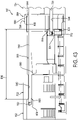
- Fig. 1 shows a medical device support system 10 in accordance with an embodiment of the invention.
- the medical device support system 10 includes a central shaft or support column 14 that is suspended from the ceiling, and three generally horizontal extension arms 16 mounted to the shaft 14 for rotational movement about the shaft 14.
- the central shaft 14 could be mounted to a wall or stand rather than the ceiling.
- Three load balancing arms 18, which are also referred to as counterbalancing arms, are mounted to the respective extension arms 16.
- the extension arms 16 and load balancing arms 18 each include a support arm structure or housing, or more generally a support arm.
- a proximal hub 22 of the load balancing arm 18 includes a support structure 24, for example the illustrative drop tube 24, that is rotatably connectable to a receptacle at the distal end 30 of the extension arm 16.
- the distal end of each load balancing arm 18 is configured with a suitable support hub 34 to support a medical device load 36.
- the medical device load 36 may include a surgical light as shown, or a supply console, a patient monitor, a camera detector head, a medical instrument, a ventilator system, a suction device, among others.
- a control console if provided, may provide controls for navigation of a medical instrument that is either coupled to or remote from the load balancing arm 18.
- the load balancing arm 18 enables positioning of the medical device 36 to a proper orientation relative to for example a patient operating table and healthcare professionals in the operating room.
- the load balancing arm 100 includes a proximal hub 104, an adjustable bearing element 108, a support arm 110, a spring 116, and one or more links, two such links 124, 126 in the illustrative embodiment, as shown in Fig. 3 and 12 .
- the proximal hub 104 may include a support structure 24 such as the drop tube 24 (see Fig. 1 ).
- the proximal hub 104 includes a main bearing element 130 that defines a main pivot axis 132.
- the adjustable bearing element 108 defines an adjustable pivot axis 142 that is adjustable relative to the main pivot axis 132.
- the support arm 110 has a proximal end 150 and a distal end 152.
- the distal end 152 is configured to support a medical device load 36 (see Fig. 1 ) and the proximal end 150 is pivotably mounted to the main bearing element 130 for pivotable movement about the main pivot axis 132. Pivotable movement about the main pivot axis 132 raises and lowers the height of the medical device load 36 at the distal end 152.
- the spring 116 extends within a cavity 154 of the support arm 110 and is mounted to exert a biasing force between the main pivot axis 132 and a distal end 158 of the spring 116.
- the links 124, 126 each have a proximal end 160 and a distal end 162.
- the proximal end 160 is pivotably mounted to the adjustable bearing element 108 for pivotable movement about the adjustable pivot axis 142.
- the distal ends 162 of the links 124, 126 are pivotably mounted to the distal end 158 of the spring 116 such that the biasing force exerted by the spring 116 is transmitted through the links 124, 126 to the adjustable bearing element 108 thereby to generate a moment about the main pivot axis 132 of the proximal hub 104 that counters a moment generated by the medical device load 36 at the distal end 152 of the support arm 110, thereby balancing the medical device load 36.
- the links 124, 126 connect at their proximal ends 160 to an adjustment bearing element 108 and at their distal ends 162 to the distal end 158 of the spring 116.
- the attachment at the distal end 158 of the spring 116 allows for a relatively longer link than if connected to the proximal end of the spring 116. The inventors have found that this allows for a better force transmission and less spring travel resulting in a more balanced load balancing arm 100 throughout the pivotable range of travel of the arm 100.
- Figs. 2-6 and 15-20 show greater detail of the support arm 110, the proximal hub 104, and the interface between the support arm 110 and proximal hub 104.
- the proximal end 150 of the support arm 110 has a relatively smaller width than the proximal hub 104 and fits within the proximal hub 104.
- the proximal end 150 of the support arm 110 includes a pair of vertically oriented laterally spaced protrusions or tongue portions 170 and a circular portion 178 substantially surrounding the tongue portions 170. As shown in Figs.
- the proximal hub 104 includes a mounting surface 184 for mounting the proximal hub 104 and thus the load balancing arm 100 to, for example, the distal end of an extension arm 16.
- the proximal hub 104 includes a pair of vertically oriented side walls 188 alongside which the tongue portions 170 of the support arm 110 slide during adjusting of the support arm 110.
- the side walls 188 have a circular shape that corresponds in diameter to the circular portion 178 of the proximal end 150 of the support arm 110.
- the proximal hub 104 also includes a load adjustment base 196 that extends width-wise between the pair of vertically oriented side walls 188 and that, as shown in Figs. 15-20 , extends vertically downward from a location just below the vertically uppermost portion of the circular portion 178 of the proximal end 150 of the support arm 110 downward approximately three fourths the distance across the circular portion 178. Details of one example of the load adjustment base 196 are shown in Figs. 9 , 10 , 12-14 and 18-20 . As shown in Fig. 10 , the load adjustment base 196 may be fastened to the side walls 188 by fasteners 198. As shown in Figs.
- the load adjustment base 196 has a pair of laterally spaced flanges 204 that are recessed inward from the outer width of the load adjustment base 196. Referring to Fig. 9 , the recessed flanges 204 form respective gaps 210 with the side walls 188 within which the tongue portions 170 of the support arm 110 are received. As shown in Figs. 9 , 12 and 18-20 , the tongue portions 170 of the proximal end 150 of the support arm 110 have through holes 236 and the main bearing element 130 of the proximal hub 104 includes a pair of laterally spaced pins 240. The central axis of these pins 240 defines or coincides with the main pivot axis 132. The through holes 236 receive the pins 240 thereby to pivotably mount the proximal end 150 of the support arm 110 to the main bearing element 130 of the proximal hub 104 for pivotable movement of the support arm 110 about the main pivot axis 132.
- bushings 244 are provided on the pins 240 to promote smooth pivotable operation and serviceability. As shown in Figs. 8 , 10 and 12 , the pins 240 are fixedly connected, for example by welding, to a retainer plate 252, which, in turn, is fastened to the side walls 188 of the proximal hub 104 by fasteners 258.
- a load adjustment screw 280 is rotatably mounted in a bottom wall 284 of the load adjustment base 196.
- the load adjustment screw 280 is fixed in a vertical orientation in the proximal hub 104 and rotates about its own central axis 290.
- the axis 290 of the load adjustment screw 280 is parallel to an axis 296 of rotation of the load balancing arm 100 extending centrally through the support structure 24 and perpendicular to horizontal. As shown in Figs.
- the adjustable bearing element 108 includes a load adjustment nut 310 that threadably engages the load adjustment screw 280 to adjust the adjustable pivot axis 142 relative to the main pivot axis 132.
- the load adjustment nut 310 moves in the vertical direction as the load adjustment screw 280 is rotated, which vertical movement adjusts the adjustable pivot axis 142 relative to the main pivot axis 132.
- the adjustable bearing element 108 includes a pin 324 that is carried by the load adjustment nut 310.
- the central axis of the pin 324 defines or coincides with the adjustable pivot axis 142.
- the proximal ends 160 of the links 124, 126 are pivotably mounted to the pin 324 at respective opposite ends of the pin 324.
- the adjustable pivot axis 142 is adjustable relative to the main pivot axis 132 over a range of adjustment 330, defined in the illustrative embodiment by the uppermost and lowermost vertical position of the load adjustment nut 310.
- the vertical movement of the load adjustment nut 310 adjusts the load capacity of the load balancing arm 100.
- the distance between the adjustable pivot axis 142 of the pin 324 and the main pivot axis 132 of the proximal hub 104 provides the mechanical advantage, or moment, that allows the load balancing arm 100 to balance a medical device load 36 at the distal end 152 of the arm 100.
- the laterally spaced pins 240 split the main pivot axis 132 thereby enabling the adjustable bearing element 108 to be moved vertically across the main pivot axis 132 into a position between the laterally spaced pins 240. Accordingly, the adjustable bearing element 108 and the proximal ends 160 of the respective pair of links 124, 126 are movable between the pair of pins 240 over a portion of the range of adjustment 330. As will be appreciated, this provides greater adjustment range in the proximal ends 160 of the links 124, 126 pivotably mounted to the pin 324 of the adjustable bearing element 108 than if the pins 240 were a single pin member and the main pivot axis 132 was not split.
- the split main pivot axis 132 i.e. laterally spaced pins 240, also enables the proximal ends 160 of the links 124, 126 to move between the pins 240 for example when the load balancing arm 100 is pivoted to lower positions.
- the adjustable pivot axis 142 of the adjustable bearing element 108 is horizontally offset from the main pivot axis 132 of the main bearing element 130 in a direction toward the portion of the proximal hub 104 that includes the support structure 24.
- This offset allows for better balancing of the spring arm when a lighthead or other medical device is attached. It also slightly changes the dynamics of the load balancing arm 100 so that when above horizontal there is slightly more mechanical advantage about the main pivot axis 132 and when below horizontal there is slightly less mechanical advantage about the main pivot axis 132. As such, this allows the load balancing arm 100 to compensate for the spring force increasing as the arm 100 is moved to lower verticle positions, for example.
- the support arm 110 includes an intermediate portion 340 between the proximal end 150 and distal end 152 of the support arm 110.
- the intermediate portion 340 has a relatively narrower height span than the circular portion 178 of the proximal end 150 of the support arm 110.
- the links 124, 126 (only link 124 is in view in Figs. 15-17 ) have at least one bend that corresponds to the difference in height span between the intermediate portion 340 and the circular portion 178 of the proximal end 150 of the support arm 110.
- the links 124, 126 have one bend and consequently have a J-shape in side view.
- the bend in the links 124, 126 aids in the load balancing arm 100 having a smaller size and lower overall cross section profile than if the links 124, 126 were straight.
- the smaller size and lower overall cross section profile make the load balancing arm 100 less obstructive in the operating room and improve the laminar airflow around the surface of the load balancing arm 100.
- the distal ends 162 of the links 124, 126 are pivotably mounted to the distal end 158 of the spring 116 via a carriage slide 364 that is slidable relative to the support arm 110.
- the pivotable connection may be facilitated by, for example, a pin 360 mounted within the carriage slide 384.
- the carriage slide 364 is slidable within at least one groove 368 in the support arm 110, wherein in the illustrative embodiment there are two such grooves 368 at laterally opposite sides of the support arm 110.
- the grooves 368 are oriented along an axis that extends radially from and perpendicular to the main pivot axis 132.
- the grooves 368 are formed by parallel ribs 370 in the inward facing walls of the support arm 110.
- the ribs 370 along with a box shape member in the lower portion of the support arm 110, also serve as stiffening members.
- the spring 116 of the load balancing arm 100 may be any type of counterbalancing member, and in the illustrative embodiment is a compression gas spring 116. Like the grooves 368, the spring 116 is oriented along an axis that extends radially from and perpendicular to the main pivot axis 132.
- the spring 116 has a cylinder 384 and a rod 388. Referring to Figs. 11 , 12 and 15-17 , the cylinder 384 has a proximal end wall 390 that is coupled to a vertical beam 392 of the support arm 110. As shown in Fig.
- the vertical beam 392 extends from a top wall 406 to a bottom wall 408 of the support arm 110 and is sufficiently narrow that the links 124, 126 straddle the vertical beam 392 on opposite lateral sides thereof throughout the pivotable range of the load balancing arm 100.
- the proximal end wall 390 of the cylinder 384 may be coupled to the vertical beam 392 in any suitable manner, for example as by a protrusion 418, shown in Fig. 12 , that fits within an opening 420 in the vertical beam 392, shown in Fig. 11 .
- the rod 388 is pivotably mounted to the distal ends 162 of the links 124, 126 via the pin 360 of the afore described carriage slide 364. In operation, the links 124, 126 straddle the spring 116 on laterally opposite sides of the spring 116 throughout the pivotable range of the load balancing arm 100.
- Figs. 15-17 show the load balancing arm 100 in three different vertical positions
- Figs. 18-20 show the links 124, 126 and the proximal end 150 of the support arm 110 relative to the proximal hub 104 in the three respective vertical positions.
- the links 124, 126 are shown adjusted to their maximum height in Figs. 15-20 , thereby maximizing the moment, or mechanical advantage, of the load balancing arm 100.
- the support arm 110 is in a substantially horizontal position.
- Figs. 16 and 19 the support arm 110 is shown pivoted about the main pivot axis 132 about 30 degrees upward relative to horizontal.
- Figs. 15-17 show the load balancing arm 100 in three different vertical positions
- Figs. 18-20 show the links 124, 126 and the proximal end 150 of the support arm 110 relative to the proximal hub 104 in the three respective vertical positions.
- the links 124, 126 are shown adjusted to their maximum height in Figs. 15-20 , thereby maximizing the moment
- the support arm 110 is shown pivoted about the main pivot axis 132 about 85 degrees downward from horizontal. As will be appreciated, then, the support arm 110 has an angle of rotation about the main pivot axis 132 of about 30 degrees upward from horizontal to about 85 degrees downward from horizontal.
- Figs. 21-38 show a load balancing arm 500 according to another embodiment of the invention.
- the load balancing arm 500 is in many respects similar to the above-referenced load balancing arm 100, and consequently the same reference numerals are used to denote structures corresponding to similar structures in the load balancing arm 100.
- the foregoing description of the load balancing arm 100 is equally applicable to the load balancing arm 500 except as noted below.
- aspects of the load balancing arms 100, 500 may be substituted for one another or used in conjunction with one another where applicable.
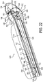
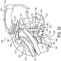
- the load balancing arm 500 includes a proximal hub 104, an adjustable bearing element 108, a support arm 110, a spring 116, and one or more links, two such links 124, 126 in the illustrative embodiment, as shown in Figs. 21-22 and 31-32 .
- the load balancing arm 500 also includes a distal hub 510 shown in Figs. 21 , 23-25 , 28 and 37-38 , a parallel link 520 shown in Figs.
- the proximal hub 104 may include a support structure 24 such as the drop tube 24 (see Fig. 1 ).
- the proximal hub 104 includes a main bearing element 130 that defines a main pivot axis 132.
- the adjustable bearing element 108 defines an adjustable pivot axis 142 that is adjustable relative to the main pivot axis 132.
- the support arm 110 has a proximal end 150 and a distal end 152.
- the distal end 152 is pivotably mounted to the distal hub 510, which, in turn, is configured to support a medical device load 36 (see Fig. 1 ).
- the proximal end 150 is pivotably mounted to the main bearing element 130 for pivotable movement about the main pivot axis 132. The pivotable movement raises and lowers the height of the medical device load 36 at the distal end 152.
- the spring 116 extends within a cavity 154 of the support arm 110 and is mounted to exert a biasing force between the main pivot axis 132 and a distal end 158 of the spring 116.
- the links 124, 126 each have a proximal end 160 and a distal end 162.
- the proximal end 160 is pivotably mounted to the adjustable bearing element 108 for pivotable movement about the adjustable pivot axis 142.
- the distal ends 162 of the links 124, 126 are pivotably mounted to the distal end 158 of the spring 116 such that the biasing force exerted by the spring 116 is transmitted through the links 124, 126 to the adjustable bearing element 108 thereby to generate a moment about the main pivot axis 132 of the proximal hub 104 that counters a moment generated by the medical device load 36 at the distal end 152 of the support arm 110, thereby balancing the medical device load 36.
- the links 124, 126 connect at their proximal ends 160 to an adjustment bearing element 108 and at their distal ends 162 to the distal end 158 of the spring 116.
- the attachment at the distal end 158 of the spring 116 allows for a relatively longer link than if connected to the proximal end of the spring 116. The inventors have found that this allows for a better force transmission and less spring travel resulting in a more balanced load balancing arm 500 throughout the pivotable range of travel of the arm 500.
- Figs. 21-27 , 31 and 34-36 show greater detail of the support arm 110, the proximal hub 104, and the interface between the support arm 110 and proximal hub 104.
- the proximal end 150 of the support arm 110 has a relatively smaller width than the proximal hub 104 and fits within the proximal hub 104.
- the proximal end 150 of the support arm 110 includes a pair of vertically oriented laterally spaced protrusions or tongue portions 170 and a circular portion 178 substantially surrounding the tongue portions 170. As shown in Figs.
- the proximal hub 104 includes a mounting surface 184 for mounting the proximal hub 104 and thus the load balancing arm 100 to, for example, the distal end of an extension arm 16.
- the proximal hub 104 includes a pair of vertically oriented side walls 188 alongside which the tongue portions 170 of the support arm 110 slide during adjusting of the support arm 110.
- the side walls 188 have a circular shape that corresponds in diameter to the circular portion 178 of the proximal end 150 of the support arm 110.
- the proximal hub 104 also includes a load adjustment base 530 that extends width-wise between the pair of vertically oriented side walls 188 and that, as shown in Figs. 22 , 27 and 34-36 extends vertically downward from a location just below the vertically uppermost portion of the circular portion 178 of the proximal end 150 of the support arm 110 downward approximately three fourths the distance across the circular portion 178.
- a load adjustment base 530 Details of one example of the load adjustment base 530 are shown in Figs. 22 , 24-27 and 31-36 .
- the load adjustment base 530 may be fastened to the side walls 188 by fasteners 198. As shown in Figs.
- the load adjustment base 530 has a pair of laterally spaced flanges 204 that are recessed inward from the outer width of the load adjustment base 530.
- the recessed flanges 204 form respective gaps 210 with the side walls 188 within which the tongue portions 170 of the support arm 110 are received.
- the tongue portions 170 of the proximal end 150 of the support arm 110 have through holes 236 and the main bearing element 130 of the proximal hub 104 includes a pair of laterally spaced pins 240.
- the central axis of these pins 240 defines or coincides with the main pivot axis 132.
- the through holes 236 receive the pins 240 thereby to pivotably mount the proximal end 150 of the support arm 110 to the main bearing element 130 of the proximal hub 104 for pivotable movement of the support arm 110 about the main pivot axis 132.
- bushings 244 are provided on the pins 240 to promote smooth pivotable operation and serviceability. As shown in Figs. 23 , 26 and 31 , the pins 240 are fixedly connected, for example by welding, to a retainer plate 252, which, in turn, is fastened to the side walls 188 of the proximal hub 104 by fasteners 258.
- a load adjustment screw 280 is rotatably mounted in a bottom wall 284 of the load adjustment base 530.
- the load adjustment screw 280 is fixed in a vertical orientation in the proximal hub 104 and rotates about its own central axis 290.
- the axis 290 of the load adjustment screw 280 is parallel to an axis 296 of rotation of the load balancing arm 500 extending centrally through the support structure 24 and perpendicular to horizontal. As shown in Figs.
- the adjustable bearing element 108 includes a load adjustment nut 310 that threadably engages the load adjustment screw 280 to adjust the adjustable pivot axis 142 relative to the main pivot axis 132.
- the load adjustment nut 310 moves in the vertical direction as the load adjustment screw 280 is rotated, which vertical movement adjusts the adjustable pivot axis 142 relative to the main pivot axis 132.
- the adjustable bearing element 108 includes a pin 324 that is carried by the load adjustment nut 310.
- the central axis of the pin 324 defines or coincides with the adjustable pivot axis 142.
- the proximal ends 160 of the links 124, 126 are pivotably mounted to the pin 324 at respective opposite ends of the pin 324.
- the adjustable pivot axis 142 is adjustable relative to the main pivot axis 132 over a range of adjustment 330, defined in the illustrative embodiment by the uppermost and lowermost vertical position of the load adjustment nut 310, as shown in Fig. 32 .
- the vertical movement of the load adjustment nut 310 adjusts the load capacity of the load balancing arm 500.
- the distance between the adjustable pivot axis 142 of the pin 324 and the main pivot axis 132 of the proximal hub 104 provides the mechanical advantage, or moment, that allows the load balancing arm 500 to balance a medical device load 36 at the distal end 152 of the arm 500.
- the laterally spaced pins 240 split the main pivot axis 132 thereby enabling the adjustable bearing element 108 to be moved vertically across the main pivot axis 132 into a position between the laterally spaced pins 240. Accordingly, the adjustable bearing element 108 and the proximal ends 160 of the respective pair of links 124, 126 are movable between the pair of pins 240 over a portion of the range of adjustment 330. As will be appreciated, this provides greater adjustment range in the proximal ends 160 of the links 124, 126 pivotably mounted to the pin 324 of the adjustable bearing element 108 than if the pins 240 were a single pin member and the main pivot axis 132 was not split.
- the adjustable pivot axis 142 of the adjustable bearing element 108 and the main pivot axis 132 of the main bearing element 130 are horizontally offset the same distance from the axis 296 of rotation of the load balancing arm 500 extending centrally through the support structure 24.
- the support arm 110 includes an intermediate portion 340 between the proximal end 150 and distal end 152 of the support arm 110.
- the intermediate portion 340 has a relatively narrower height span than the circular portion 178 of the proximal end 150 of the support arm 110.
- the links 124, 126 (only link 124 is in view in Figs. 34-36 ) have at least one bend that corresponds to the difference in height span between the intermediate portion 340 and the circular portion 178 of the proximal end 150 of the support arm 110.
- the links 124, 126 have one bend and consequently have a J-shape in side view.
- the bend in the links 124, 126 aids in the load balancing arm 500 having a smaller size and lower overall cross section profile than if the links 124, 126 were straight.
- the smaller size and lower overall cross section profile make the load balancing arm 500 less obstructive in the operating room and improve the laminar airflow around the surface of the load balancing arm 100.
- the distal ends 162 of the links 124, 126 are pivotably mounted to the distal end 158 of the spring 116 via a carriage slide 364 that is slidable relative to the support arm 110.
- the pivotable connection may be facilitated by, for example, a pin 360 mounted within the carriage slide 384.
- the carriage slide 364 is slidable within at least one groove 368 in the support arm 110, wherein in the illustrative embodiment there are two such grooves 368 at laterally opposite sides of the support arm 110.
- the grooves 368 are oriented along an axis that extends radially from and perpendicular to the main pivot axis 132.
- the grooves 368 are formed by parallel ribs 370 in the inward facing walls of the support arm 110.
- the ribs 370 along with a horizontal cross beam in the bottom portion of the support arm 110, also serve as stiffening members.
- the spring 116 of the load balancing arm 500 may be any type of counterbalancing member, and in the illustrative embodiment is a compression gas spring 116. Like the grooves 368, the spring 116 is oriented along an axis that extends radially from and perpendicular to the main pivot axis 132.
- the spring 116 has a cylinder 384 and a rod 388. Referring to Figs. 22 , 24 , 27 and 32 , the cylinder 384 has a proximal end wall 390 that is coupled to a vertical beam 392 of the support arm 110. As shown in Fig.
- the vertical beam 392 extends from a top wall 406 to a bottom wall 408 of the support arm 110 and is sufficiently narrow that the links 124, 126 straddle the vertical beam 392 on opposite lateral sides thereof throughout the pivotable range of the load balancing arm 500.
- the proximal end wall 390 of the cylinder 384 may be coupled to the vertical beam 392 in any suitable manner, for example as by a protrusion 418, shown in Fig. 32 , that fits within an opening 420 in the vertical beam 392, shown in Figs. 24 and 25 .
- the rod 388 is pivotably mounted to the distal ends 162 of the links 124, 126 via the pin 360 of the afore described carriage slide 364. In operation, the links 124, 126 straddle the spring 116 on laterally opposite sides of the spring 116 throughout the pivotable range of the load balancing arm 500.
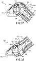
- Figs. 21 , 23-25 , 28 and 37-38 show detail of the distal hub 510 of the load balancing arm 500.
- the distal hub 510 is pivotably connected to the distal end 152 of the support arm 110 via a pair of laterally spaced pins 540 held in flanges of a vertical block 544 of the distal hub 510.
- the vertical block 544 can be fixedly connected to a pair of vertically oriented side walls 548 of the distal hub 510 in a similar manner that the load adjustment base 530 is connected to the side walls 188 of the proximal hub 104.
- the distal end 152 of the support arm 110 can include laterally spaced protrusions 566 that pivotably connect to the respective laterally spaced pins 540 in a similar manner that the proximal end protrusions 170 pivotably connect to the laterally spaced pins 240 of the proximal hub 104.
- Figs. 22 , 25 , 27-32 and 34-38 show detail of the parallel link 520 of the load balancing arm 500.
- the illustrative parallel link 520 is a single U-shape link with two vertically oriented laterally spaced parallel side walls 564 and a lower bridge member 568 connecting the bottom edges of the side walls 564. It will be appreciated that the parallel link 520 may comprise two parallel links in the form of the two parallel side walls 564 with the lower bridge member 568 omitted. Referring to Figs.
- the parallel link 520 is made up of two pieces, a U-shape stainless steel member 570 and a pair of relatively harder stainless steel side braces 572 tack welded to the U-shape stainless steel member 570.
- the parallel link 520 is pivotably connected at its proximal end 580 to a pin 582 supported by the load adjustment base 530 of the proximal hub 104 and at its distal end 586 to a pin 588 supported by the vertical block 544 of the distal hub 510.
- the split main pivot axis 132 i.e. the laterally spaced pins 240
- the split pivot axis 590 i.e. the laterally spaced pins 540
- the pin 582 is oriented vertically below the pins 240 a distance 600 and the pin 588 is oriented vertically below the pins 540 by the same distance 600. Also, the horizontal distance between the pins 540 and the pins 240 at opposite ends of the support arm 110 is equal to the horizontal distance between the pin 588 and the pin 582 at opposite ends of the parallel link 520.
- a parallelogram is formed by the structure of the support arm 110 between the pins 540 and the pins 240, the portion of the load adjustment base 530 between the pins 240 and the pin 582, the parallel link 520 between the pin 582 and the pin 588, and the portion of the vertical block 544 between the pin 588 and the pins 540.
- the vertically aligned pins 540, 588 at the distal end 152 remain parallel to the vertically aligned pins 240, 582 at the proximal end 150 throughout the pivotable range of the load balancing arm 500 about the main pivot axis 132. This permits a medical device load 36 such as a monitor to remain properly oriented regardless of its vertical displacement from the ceiling of the operating room.
- the side walls 564 of the parallel link 520 straddle the vertically lower portion of the gas spring 116 on laterally opposite sides thereof.
- the side walls 564 also straddle the links 124, 126 on laterally opposite sides of the links 124, 126 over at least a portion of the pivotable range of the load adjustment arm 500, particularly when the adjustable bearing element 108 is in lower positions as shown in Fig. 24 .
- Figs. 34-36 show the load balancing arm 500 in three different vertical positions
- Figs. 37 and 38 show the parallel link 520 and the distal end 152 of the support arm 110 relative to the distal hub 510 in the respective uppermost and lowermost vertical positions.
- the links 124, 126 are shown adjusted to their maximum height in Figs. 34-36 , thereby maximizing the moment, or mechanical advantage, of the load balancing arm 500.
- the support arm 110 is in a substantially horizontal position.
- Figs. 35 and 37 the support arm 110 is shown pivoted about the main pivot axis 132 about 40 degrees upward relative to horizontal.
- Figs. 34-36 show the load balancing arm 500 in three different vertical positions
- Figs. 37 and 38 show the parallel link 520 and the distal end 152 of the support arm 110 relative to the distal hub 510 in the respective uppermost and lowermost vertical positions.
- the links 124, 126 are shown adjusted to their maximum height in Figs. 34-36 ,
- the support arm 110 is shown pivoted about the main pivot axis 132 about 40 degrees downward from horizontal. As will be appreciated, then, the support arm 110 has an angle of rotation about the main pivot axis 132 of about 40 degrees upward from horizontal to about 40 degrees downward from horizontal.
- the support arm 110 has a longitudinal axis 700 and along that axis 700 the support arm 110 includes a proximal hub 720 at its proximal end 150, a distal hub 722 at its distal end 152, and an intermediate beam 724 between the proximal hub 720 and the distal hub 722.
- the proximal hub 720 may be referred to as an inner proximal hub 720 while the proximal hub 104 may be referred to as an outer proximal hub 104.
- a cavity 736 extends longitudinally through the intermediate beam 724 the entire length of the intermediate beam 724.
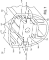
- At least one tension member four such tension members 750, 752, 754, 756 (collectively 750-756) in the illustrative embodiment, extend through the cavity 736 of the intermediate beam 724.
- the tension members 750-756 are secured at their proximal ends 760 to the proximal hub 720 and at their distal ends 762 to the distal hub 722.
- the tension members 750-756 are in a state of tension and the intermediate beam 724 is in a state of compression.
- the intermediate beam 724 can be said to be "sandwiched" between the proximal hub 720 and distal hub 722.
- the tension members 750-756 allow for a more compact and lighter weight support arm 110, and thus load balancing arm 100, than what was heretofore provided, and a support arm 110 that has no visible fasteners.
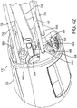
- the tension members 750-756 extend through the intermediate beam 724 without contacting or engaging the intermediate beam 724. This can be seen for example in Fig. 7 . It will be appreciated that although the illustrative tension members 750-756 have the same length, in alternative embodiments the tension members 750-756 may have different lengths as the case may be. As shown in Figs. 39-41 , the proximal ends 760 of the tension members 750-756 connect to the inner proximal hub 720. The inner proximal hub 720, in turn, fits within and is pivotably connected to the outer proximal hub 104, as earlier described. As shown in Figs. 39 , 42 and 43 , the distal ends 762 of the tension members 750-756 connect to the distal hub 722. The distal hub 722, in turn, supports a medical device load 36, as shown in Fig. 1 .
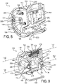
- Figs. 40 and 41 show greater detail of the connection between the proximal hub 720 and the intermediate beam 724.
- the proximal hub 720 has two threaded holes 780, 782 in an upper portion of the proximal hub 720 and two threaded holes 784, 786 in a lower portion of the proximal hub 720.
- the proximal hub 720 includes a tubular end wall 800 that mates with a proximal end 804 of the intermediate beam 724, and the two upper threaded holes 780, 782 are in bosses 810, 812 that project radially inwardly from an inward facing wall 828 of the tubular end wall 800.
- the two lower threaded holes 784, 786 are in the vertical beam 392 that extends from the top wall 406 to the bottom wall 408 of the proximal hub 720.
- the two lower threaded holes 784, 786 are horizontally offset a distance 836 from the two upper threaded holes 780, 782 along the longitudinal axis 700 in a direction toward the main pivot axis 132 or axis 296 of rotation of the load balancing arm 100.
- the two upper tension members 750, 752 are threaded at their proximal ends 760 for threaded engagement with the threaded holes 780, 782 in the bosses 810, 812.
- the two lower tension members 754, 756 are threaded at their proximal ends 760 for threaded engagement with the threaded holes 784, 786 in the vertical beam 392.
- the proximal ends 760 of the tension members 750-756 are threaded into the respective threaded holes 780-786 to secure or fixedly connect the tension members 750-756 to the proximal hub 720.
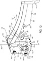
- Figs. 42 and 43 show greater detail of the connection between the distal hub 722 and the intermediate beam 724.
- the distal hub 722 has two clearance holes 840, 842 in an upper portion of the distal hub 722 and two clearance holes 844, 846 in a lower portion of the distal hub 722.
- the distal hub 722 includes a tubular end wall 860 that mates with a distal end 864 of the intermediate beam 724, and the two upper clearance holes 840, 842 and two lower clearance holes 844, 846 are in bosses 880, 882, 884, 886 that project radially inwardly from an inward facing wall 888 of the tubular end wall 860.
- the two lower clearance holes 844, 846 are horizontally offset a distance 896 from the two upper clearance holes 840, 842 along the longitudinal axis 700 in a direction toward the main pivot axis 132 or axis 296 of rotation of the load balancing arm 100.
- the two upper tension members 750, 752 pass through the clearance holes 840, 842 in the bosses 880, 882 such that their distal ends 762 are exposed.
- the two lower tension members 754, 756 pass through the clearance holes 844, 846 in the bosses 884, 886 such that their distal ends 762 are exposed.
- the exposed distal ends 762 of the tension members 750-756 are threaded.
- Retainers 900, 902, 904, 906 such as the illustrative cylindrical nuts 900, 902, 904, 906 thread onto the exposed distal ends 762 of the tension members 750-756 such that the retainers 900, 902, 904, 906 abut respective flats 920, 922, 924, 926 of the bosses 880-886.
- the retainers 900-906 draw the tension members 750-756 through the clearance holes 840-846, urging the proximal hub 720 and the distal hub 722 toward one another.
- the proximal hub 720 and distal hub 722 compress the intermediate beam 724 therebetween, generating a tensile load in the tension members 750-756 and a compressive load in the intermediate beam 724.
- the tensile loaded tension members 750-756 and compressively loaded intermediate beam 724 hold the proximal hub 720, distal hub 722 and intermediate beam 724 together along the longitudinal axis 700.
- the retainers 900-906 are tightened to a specific torque rating suitable for maintaining the proximal hub 720, distal hub 722 and intermediate beam 724 secured together.
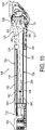
- Figs. 44-47 show examples of mating walls of the proximal hub 720, distal hub 722 and intermediate beam 724.
- the proximal hub 720 includes a tubular end wall 800 that mates with a tubular end wall 940 at the proximal end 804 of the intermediate beam 724.
- the distal hub 722 includes a tubular end wall 860 that mates with a tubular end wall 944 at the distal end 864 of the intermediate beam 724.
- the tubular end walls 800, 860, 940, 944 have a noncircular shape in axial cross section.
- the tubular end wall 800 of the proximal hub 720 has an outer periphery that is slightly smaller than the inner periphery of the tubular end wall 940 of the intermediate beam 724. Accordingly, tubular end wall 800 of the proximal hub 720 fits into the tubular end wall 940 of the intermediate beam 724 such that the tubular end walls 800, 940 overlap along the longitudinal axis 700.
- the tubular end wall 860 of the distal hub 722 has an outer periphery that is slightly smaller than the inner periphery of the tubular end wall 944 of the intermediate beam 724.
- tubular end wall 860 of the distal hub 722 fits into the tubular end wall 944 of the intermediate beam 724 such that the tubular end walls 860, 944 overlap along the longitudinal axis 700.
- torsional loading is transferred from the tubular end wall 800 to the tubular end wall 940 and vice versa, and from the tubular end wall 860 to the tubular end wall 944 and vice versa. This substantially eliminates or minimizes torsional loading on the tension members 750-756.
- the tubular end wall 800 of the proximal hub 720 has a shoulder 954 and the tubular end wall 940 of the intermediate beam 724 has a stop face 958 that abuts the shoulder 954 when the proximal hub 720 is connected to the intermediate beam 724.
- the tubular end wall 860 of the distal hub 722 has a shoulder 964 and the tubular end wall 944 of the intermediate beam 724 has a stop face 968 that abuts the shoulder 954 when the proximal hub 720 is connected to the intermediate beam 724.
- the thickness of the shoulders 954, 964 is the same as that of the stop faces 958, 968 to provide a smooth transition in the outer surfaces of the proximal hub 720, the distal hub 722, and the intermediate beam 724 along the longitudinal axis 700, which improves the laminar airflow around the surface of the load balancing arm 100.
- the tension members 750-756 can be made of any suitable tensile load bearing member, including for example a threaded rod, a steel cable, a plastic cable, among others.
- the intermediate beam 724 is an extruded member and the proximal hub 720 and distal hub 722 are cast members. It will be appreciated, of course, that other manufacturing processes may be used such as pultrusion and additive manufacturing techniques.
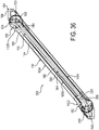
- Figs. 48-56 show greater detail of the support arm 110, or support arm structure or housing, of the Fig. 21 load balancing arm 500 in accordance with an embodiment of the invention.
- the Fig. 48 support arm 110 is in many respects similar to the above-referenced Fig. 39 support arm 110, and consequently the same reference numerals are used to denote structures corresponding to similar structures in the Fig. 39 support arm 110.
- the foregoing description of the Fig. 39 support arm 110 is equally applicable to the Fig. 48 support arm 110 except as noted below.
- aspects of the Fig. 39 and Fig. 48 supports arms 110 may be substituted for one another or used in conjunction with one another where applicable.
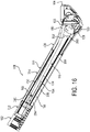
- the support arm 110 has a longitudinal axis 1000 and along that axis 1000 the support arm 110 includes a proximal hub 1020 at its proximal end 150, a distal hub 1022 at its distal end 152, and an intermediate beam 1024 between the proximal hub 1020 and the distal hub 1022.
- the proximal hub 1020 may be referred to as an inner proximal hub 1020 while the proximal hub 104 may be referred to as an outer proximal hub 104.
- the distal hub 1022 may be referred to as an inner distal hub 1022 while the distal hub 510 may be referred to as an outer distal hub 510.
- a cavity 1036 extends longitudinally through the intermediate beam 1024 the entire length of the intermediate beam 1024. At least one tension member, four such tension members 1050, 1052, 1054, 1056 (collectively 1050-1056) in the illustrative embodiment, extend through the cavity 1036 of the intermediate beam 1024.
- the tension members 1050-1056 are secured at their proximal ends 1060 to the proximal hub 1020 and at their distal ends 1062 to the distal hub 1022.
- the tension members 1050-1056 are in a state of tension and the intermediate beam 1024 is in a state of compression.
- the intermediate beam 1024 can be said to be "sandwiched" between the proximal hub 1020 and distal hub 1022.
- the tension members 1050-1056 allow for a more compact and lighter weight support arm 110, and thus load balancing arm 500, than what was heretofore provided, and a support arm 110 that has no visible fasteners.
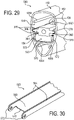
- the tension members 1050-1056 extend through the intermediate beam 1024 without contacting or engaging the intermediate beam 1024. This can be seen for example in Fig. 29 . It will be appreciated that although the illustrative tension members 1050-1056 have the same length, in alternative embodiments the tension members 1050-1056 may have different lengths as the case may be. As shown in Figs. 48-50 , the proximal ends 1060 of the tension members 1050-1056 connect to the inner proximal hub 1020. The inner proximal hub 1020, in turn, fits within and is pivotably connected to the outer proximal hub 104, as earlier described. As shown in Figs.
- the distal ends 1062 of the tension members 1050-1056 connect to the distal hub 1022.
- the distal hub 1022 fits within and is pivotably connected to the outer distal hub 510, as earlier described.
- the outer distal hub 510 supports a medical device load 36, as was described with respect to Fig. 1 .
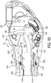
- Figs. 49 and 50 show greater detail of the connection between the proximal hub 1020 and the intermediate beam 1024.
- the proximal hub 1020 has two threaded holes 1080, 1082 in an upper portion of the proximal hub 1020 and two threaded holes 1084, 1086 in a lower portion of the proximal hub 1020.
- the proximal hub 1020 includes a tubular end wall 1100 that mates with a proximal end 1104 of the intermediate beam 1024, and the two upper threaded holes 1080, 1082 and the two lower threaded holes 1084, 1086 are in bosses 1110, 1112, 1114, 1116 that project radially inwardly from an inward facing wall 1128 of the tubular end wall 1100.
- the two upper tension members 1050, 1052 are threaded at their proximal ends 1060 for threaded engagement with the threaded holes 1080, 1082 in the bosses 1110, 1112.
- the two lower tension members 1054, 1056 are threaded at their proximal ends 1060 for threaded engagement with the threaded holes 1084, 1086 in the bosses 1114, 1116.
- the proximal ends 1060 of the tension members 1050-1056 are threaded into the respective threaded holes 1080-1086 to secure or fixedly connect the tension members 1050-1056 to the proximal hub 1020.
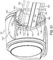
- Figs. 51 and 52 show greater detail of the connection between the distal hub 1022 and the intermediate beam 1024.
- the distal hub 1022 has two clearance holes 1140, 1142 in an upper portion of the distal hub 1022 and two clearance holes 1144, 1146 in a lower portion of the distal hub 1022.
- the distal hub 1022 includes a tubular end wall 1160 that mates with a distal end 1164 of the intermediate beam 1024, and the two upper clearance holes 1140, 1142 and two lower clearance holes 1144, 1146 are in bosses 1180, 1182, 1184, 1186 that project radially inwardly from an inward facing wall 1188 of the tubular end wall 1160.
- the two upper tension members 1050, 1052 pass through the clearance holes 1140, 1142 in the bosses 1180, 1182 such that their distal ends 1062 are exposed.
- the two lower tension members 1054, 1056 pass through the clearance holes 1144, 1146 in the bosses 1184, 1186 such that their distal ends 1062 are exposed.
- the exposed distal ends 1062 of the tension members 1050-1056 are threaded.
- Retainers 1200, 1202, 1204, 1206 such as the illustrative cylindrical nuts 1200, 1202, 1204, 1206 thread onto the exposed distal ends 1062 of the tension members 1050-1056 such that the retainers 1200, 1202, 1204, 1206 abut respective flats 1220, 1222, 1224, 1226 of the bosses 1180-1186.
- the retainers 1200-1206 are tightened to a specific torque rating suitable for maintaining the proximal hub 1020, distal hub 1022 and intermediate beam 1024 secured together.
- the retainers 1200-1206 draw the tension members 1050-1056 through the clearance holes 1140-1146, urging the proximal hub 1020 and the distal hub 1022 toward one another.
- the proximal hub 1020 and distal hub 1022 compress the intermediate beam 1024 therebetween, generating a tensile load in the tension members 1050-1056 and a compressive load in the intermediate beam 1024.
- the tensile loaded tension members 1050-1056 and compressively loaded intermediate beam 1024 hold the proximal hub 1020, distal hub 1022 and intermediate beam 1024 together along the longitudinal axis 1000.
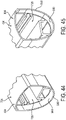
- Figs. 53-56 show examples of mating walls of the proximal hub 1020, distal hub 1022 and intermediate beam 1024.
- the proximal hub 1020 includes a tubular end wall 1100 that mates with a tubular end wall 1240 at the proximal end 1104 of the intermediate beam 1024.
- the distal hub 1022 includes a tubular end wall 1160 that mates with a tubular end wall 1244 at the distal end 1164 of the intermediate beam 1024.
- the tubular end walls 1100, 1160, 1240, 1244 have a noncircular shape in axial cross section.
- the tubular end wall 1100 of the proximal hub 1020 has an outer periphery that is slightly smaller than the inner periphery of the tubular end wall 1240 of the intermediate beam 1024. Accordingly, tubular end wall 1100 of the proximal hub 1020 fits into the tubular end wall 1240 of the intermediate beam 724 such that the tubular end walls 1100, 1240 overlap along the longitudinal axis 1000.
- the tubular end wall 1160 of the distal hub 1022 has an outer periphery that is slightly smaller than the inner periphery of the tubular end wall 1244 of the intermediate beam 1024.
- tubular end wall 1160 of the distal hub 1022 fits into the tubular end wall 1244 of the intermediate beam 1024 such that the tubular end walls 1160, 1244 overlap along the longitudinal axis 1000.
- cross section shapes are noncircular, torsional loading is transferred from the tubular end wall 1100 to the tubular end wall 1240 and vice versa, and from the tubular end wall 1160 to the tubular end wall 1244 and vice versa. This substantially eliminates or minimizes torsional loading on the tension members 1050-1056.
- the tubular end wall 1100 of the proximal hub 1020 has a shoulder 1254 and the tubular end wall 1240 of the intermediate beam 1024 has a stop face 1258 that abuts the shoulder 1254 when the proximal hub 1020 is connected to the intermediate beam 1024.
- the tubular end wall 1160 of the distal hub 1022 has a shoulder 1264 and the tubular end wall 1244 of the intermediate beam 1024 has a stop face 1268 that abuts the shoulder 1254 when the proximal hub 1020 is connected to the intermediate beam 1024.
- the thickness of the shoulders 1254, 1264 is the same as that of the stop faces 1258, 1268 to provide a smooth transition in the outer surfaces of the proximal hub 1020, the distal hub 1022, and the intermediate beam 1024 along the longitudinal axis 1000, which improves the laminar airflow around the surface of the load balancing arm 500.
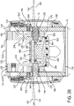
- the proximal hub 1020 and distal hub 1022 include respective upper plugs 1300, 1302 and lower plugs 1310, 1312 that fit, or plug, into respective upper receptacles 1340, 1342 and lower receptacles 1350, 1352 in the proximal and distal ends 1104, 1164 of the intermediate beam 1024.
- the upper bosses 1110, 1112 of the proximal hub 1020 form part of the upper plug 1300 of the proximal hub 1020; the lower bosses 1114, 1116 of the proximal hub 1020 form part of the lower plug 1310 of the proximal hub 1020; the upper bosses 1180, 1182 of the distal hub 1022 form part of the upper plug 1302 of the distal hub 1020; and the lower bosses 1184, 1186 of the distal hub 1022 form part of the lower plug 1312 of the distal hub 1022.
- the upper plug 1300 of the proximal hub 1020 has an inverted U-shape in which the base 1360 abuts an upper inward facing wall 1364 of the intermediate beam 1024 and the distal ends 1366 of the legs 1368, 1370 abut respective upper surfaces 1374, 1376 of the parallel ribs 370 in the laterally opposite side walls of the intermediate beam 1024.
- the lower plug 1310 of the proximal hub 1020 has a U-shape in which the base 1390 abuts a lower inward facing wall 1394 of the intermediate beam 1024 and the distal ends 1396 of the legs 1398, 1400 abut a lower surface 1404 of a cross beam 1408 extending between laterally opposite side walls of the intermediate beam 1024.
- the abutting contact between the leg 1368 and the upper surface 1374 and the abutting contact between the leg 1400 and the lower surface 1404 further aid in transferring torsional loading from the proximal hub 1020 to the proximal end 1104 of the intermediate beam 1024 and vice versa in one torsional direction
- the abutting contact between the leg 1366 and upper surface 1376 and the abutting contact between the leg 1398 and the lower surface 1404 further aid in transferring torsional loading from the proximal hub 1020 to the proximal end 1104 of the intermediate beam 1024 and vice versa in an opposite torsional direction.
- the upper plug 1302 of the distal hub 1022 has an inverted U-shape in which the base 1560 abuts the upper inward facing wall 1364 of the intermediate beam 1024 and the distal ends 1566 of the legs 1568, 1570 abut respective upper surfaces 1374, 1376 of the parallel ribs 370 in the laterally opposite side walls of the intermediate beam 1024.
- the lower plug 1312 of the distal hub 1022 has a U-shape in which the base 1590 abuts the lower inward facing wall 1394 of the intermediate beam 1024 and the distal ends 1596 of the legs 1598, 1600 abut the lower surface 1404 of the cross beam 1408 extending between laterally opposite side walls of the intermediate beam 1024.
- the abutting contact between the leg 1568 and the upper surface 1374 and the abutting contact between the leg 1600 and the lower surface 1404 further aid in transferring torsional loading from the distal hub 1022 to the distal end 1164 of the intermediate beam 1024 and vice versa in one torsional direction
- the abutting contact between the leg 1566 and upper surface 1376 and the abutting contact between the leg 1598 and the lower surface 1404 further aid in transferring torsional loading from the distal hub 1022 to the distal end 1164 of the intermediate baem 1024 and vice versa in an opposite torsional direction.
- the tension members 1050-1056 can be made of any suitable tensile load bearing member, including for example a threaded rod, a steel cable, a plastic cable, among others.
- the intermediate beam 1024 is an extruded member and the proximal hub 1020 and distal hub 1022 are cast members. It will be appreciated, of course, that other manufacturing processes may be used such as pultrusion and additive manufacturing techniques.
- a flowchart 1700 of a method of assembling a support arm of a medical device support system such as a support arm 110 for an extension arm 16 or load balancing arm 18 in the medical device support system 10 of Fig. 1 .
- a proximal hub 720 is provided that has at least one elongated tension member 750 fixed to the proximal hub 720 with a free end 762 extending away from the proximal hub 720.
- an intermediate beam 724 is provided that has a cavity 736.
- the free end 762 of the at least one elongated tension member 750 is inserted into and through the cavity 736 of the intermediate beam 724.
- the free end 762 is inserted into a distal hub 722 so that the intermediate beam 724 is between the proximal hub 720 and the distal hub 722.
- the free end 762 is tightened to the distal hub 722 so that the at least one tension member 750 is in a state of tension and the intermediate beam 724 is in a state of compression.
- the free end 762 of the at least one tension member 750 may be a threaded end and the tightening may include tightening a threaded nut 900 onto the threaded end 762.
- the inserting may include inserting the free end 762 into a clearance hole 840 inside the distal hub 722.
Description
- This application relates generally to a support arm for a medical device support system or carry system for use in, for example, a hospital examination room, a clinic, a surgery room or an emergency room, and more particularly to a support arm that is more compact and lighter in weight.
- Medical device support systems, also referred to as suspension systems and carry systems, are used in health treatment settings such as hospital examination rooms, clinics, surgery rooms and emergency rooms. These systems may suspend or support any variety of medical devices or components including surgical lights, supply consoles, patient monitors, camera detector heads, medical instruments, ventilator systems, suction devices, among others. The support systems typically include a central shaft or support column that is suspended from the ceiling or mounted to a wall, one or more generally horizontal extension arms mounted for rotational movement about the shaft, and one or more load balancing arms, also known as counterbalancing arms, that enable positioning of a medical device to a proper orientation relative to for example a patient operating table and healthcare professionals in the operating room. The extension arms and load balancing arms each include a support arm structure or housing, or more generally a support arm.
- The following patent documents relate to systems and devices in this field of technology.
-
WO-01/45627 -
US-5460894 relates to a support arm for a control device and the like, the hollow profiled walls of which enclose an installation conduit for receiving cables or the like. -
US-2004/188578 relates to a surgical theater system that includes a boom rotating about a hub and coupled to a counterbalance arm assembly. - For support arms in some medical device support systems or carry systems there remain various shortcomings, drawbacks, and disadvantages relative to certain applications. A support arm may include a proximal hub, a distal hub, and an intermediate beam between the proximal hub and distal hub. The proximal hub and distal hub connect to the intermediate beam by means of bolts. The mounting structure in the intermediate beam may consist of a plurality of threaded hole bosses on an inward facing wall of the intermediate beam, and the mounting structure in the proximal hub and distal hub may consist of a plurality of clearance hole bosses on an inward facing wall of the hubs. The bolts pass through the clearance holes of the hub bosses and thread into the threaded bosses of the intermediate beam thereby to fasten the hubs to the intermediate beam.
- One problem is that the bolts and their mounting structure, such as the bosses on the inward facing walls of the components, can occupy a significant amount of space. The space footprint ultimately affects the overall profile of the support arm. Generally, the larger the space occupied by the mounting structure, the larger is the profile of the support arm. This is undesirable not only in terms of aesthetics but also in terms of industry demands to provide smaller more streamlined medical device support systems in health treatment facilities. A larger mounting structure and thus larger profile support arm also is more obstructive of laminar flow in the operating theater, making reduced volume components more desirable.
- The mounting structure also contributes to the overall weight of the support arm. For example, the intermediate beam of the support arm requires material for drilling and tapping. Futher, the material in the corresponding proximal hub and distal hub must have a thickness that is at least wide enough to support the head of the fastening member. Where the intermediate beam is an extruded member the material of the mounting structure, for example the bosses, may extend the entire length of the intermediate beam. A lighter wieght support arm is desirable for several reasons. Lighter weight support arms are easier for healthcare professionals to manipulate. They are also easier for technicians to assemble and service.
- A further problem with some mounting structures is that their mounting fasteners may be visible. Increasingly, the industry has sought to minimize the quantity of visible fasteners.
- Accordingly, there remains a need for further contributions in this area of technology.
- The application relates to a support arm, such as an extension arm or load balancing arm, for a medical device support system, in which the support arm utilizes a tension member that holds its structure together and allows for a more compact and lighter weight support arm than what was heretofore provided, and a support arm that has no visible fasteners.
- The invention is defined by the independent claims 1 and 13 with further preferred embodiments disclosed by the further dependent claims.
- According to one aspect of the invention, a support arm for a medical device support system, includes a proximal hub and a distal hub; an intermediate beam between the proximal hub and the distal hub, the intermediate beam having a cavity; and, at least one tension member extending through the cavity of the intermediate beam and secured at opposite ends to the proximal hub and the distal hub, the tension member securing the proximal hub, the distal hub, and the intermediate beam together.
- Embodiments of the invention may include one or more of the following additional features separately or in combination.
- The at least one tension member may be in a state of tension and the intermediate beam may be in a state of compression.
- The at least one tension member may not contact or engage the intermediate beam.
- The at least one tension member may comprise any quantity of tension members, such as four tension members.
- The at least one tension member may comprise at least two tension members that have different lengths.
- The proximal hub may include at least one threaded hole and the at least one tension member may be a threaded tension member that threads into the at least one threaded hole.
- The distal hub may include at least one clearance hole and the least one tension member may pass through the at least one clearance hole such that an end of the at least one tension member is exposed.
- The at least one tension member may be a threaded tension member, and the support arm may further include a retainer that threads onto the exposed end and abuts a flat of the distal hub.
- The retainer may comprise a cylindrical nut.
- The at least one tension member may be selected from the group consisting of a threaded rod, a steel cable, and a plastic cable.
- The proximal hub may include a noncircular tubular end wall that fits into a corresponding shape end wall of the intermediate beam such that the noncircular tubular end wall overlaps with the corresponding shape end wall.
- The noncircular tubular end wall may have a shoulder and the corresponding shape end wall of the intermediate beam may have a stop face that abuts the shoulder.
- The proximal hub may include an end wall with a shoulder and the intermediate beam may include an end wall with a stop face that abuts the shoulder.
- The intermediate beam may have a noncircular tubular shape in axial cross section.
- The proximal hub may include upper and lower plugs that fit into respective upper and lower receptacles of the intermediate beam.
- The intermediate beam may be an extruded member.
- The proximal hub may be a cast member.
- According to another aspect of the invention, there is provided a method of assembling a support arm of a medical device support system, including providing a proximal hub having at least one elongated tension member fixed to the proximal hub with a free end extending away from the proximal hub; providing an intermediate beam having a cavity; inserting the free end of the at least one elongated tension member into and through the cavity of the intermediate beam; inserting the free end into a distal hub so that the intermediate beam is between the proximal hub and the distal hub; and, tightening the free end to the distal hub so that the at least one tension member is in a state of tension and the intermediate beam is in a state of compression.
- Embodiments of the invention may include one or more of the following additional features separately or in combination.
- The free end of the at least one tension member may be a threaded end and the tightening may include tightening a threaded nut onto the threaded end.
- The inserting the free end into the distal hub may include inserting the free end into a clearance hole inside the distal hub.
- The following description and the annexed drawings set forth certain illustrative embodiments of the invention. These embodiments are indicative, however, of but a few of the various ways in which the principles of the invention may be employed. Other objects, advantages and novel features according to aspects of the invention will become apparent from the following detailed description when considered in conjunction with the drawings.
- The annexed drawings, which are not necessarily to scale, show various aspects of the invention.
-
Fig. 1 is a perspective view of a medical device support system in accordance with an embodiment of the invention. -
Fig. 2 is a side perspective view of a load balancing arm in accordance with an embodiment of the invention. -
Fig. 3 is a view similar toFig. 2 with a support arm structure removed to show internal components of the load balancing arm. -
Fig. 4 is a side view of theFig. 2 load balancing arm. -
Fig. 5 is a top view of theFig. 2 load balancing arm. -
Fig. 6 is an end perspective view of theFig. 2 load balancing arm, showing at a distal end thereof a connection receptacle for receipt of a medical device. -
Fig. 7 is cross section view of theFig. 2 load balancing arm as viewed from the plane 7-7 inFig. 6 . -
Fig. 8 is a cross section view of theFig. 2 load balancing arm as viewed from the plane 8-8 inFig. 4 . -
Fig. 9 is a cross section view of theFig. 2 load balancing arm as viewed from the plane 9-9 inFig. 4 , without the proximal hub to show internal components of the load balancing arm. -
Fig. 10 is a cross section view of theFig. 2 load balancing arm as viewed from the plane 10-10 inFig. 4 . -
Fig. 11 is a cross section view of theFig. 2 load balancing arm as viewed from the plane 11-11 inFig. 4 . -
Fig. 12 is a perspective view of a proximal end of the load balancing arm, showing internal components of the load balancing arm. -
Fig. 13 is a side perspective view of a load adjustment block of a proximal hub of theFig. 2 load balancing arm. -
Fig. 14 is a top perspective view of the load adjustment block of the proximal hub of theFig. 2 load balancing arm. -
Fig. 15 is a side cross section view of theFig. 2 load balancing arm in a substantially horizontal position, showing internal components of the load balancing arm. -
Fig. 16 is a side cross section view of theFig. 2 load balancing arm in a position upward from horizontal, showing internal components of the load balancing arm. -
Fig. 17 is a side cross section view of theFig. 2 load balancing arm in a position downward from horizontal, showing internal components of the load balancing arm. -
Fig. 18 is a perspective view of the proximal end of theFig. 2 load balancing arm in a substantially horizontal position, with a cover removed to show internal components of the load balancing arm. -
Fig. 19 is a perspective view of the proximal end of theFig. 2 load balancing arm in a position upward from horizontal, with a cover removed to show internal components of the load balancing arm. -
Fig. 20 is a perspective view of the proximal end of theFig. 2 load balancing arm in a position downward from horizontal, with a cover removed to show internal components of the load balancing arm. -
Fig. 21 is a top perspective view of a load balancing arm in accordance with another embodiment of the invention, with a support arm structure removed to show internal components of the load balancing arm. -
Fig. 22 is a partial top perspective view of theFig. 21 load balancing arm, shown in partial cross section to show internal components of the load balancing arm. -
Fig. 23 is a side view of theFig. 21 load balancing arm, enlarged to show the proximal and distal ends in more detail. -
Fig. 24 is a side cross section view of theFig. 21 load balancing arm as viewed from the plane 24-24 inFig. 25 , as though the load balancing arm inFig. 25 were whole. -
Fig. 25 is a top cross section side view of theFig. 21 load balancing arm as viewed from the plane 25-25 inFig. 24 , as though the load balancing arm inFig. 24 were whole. -
Fig. 26 is an end cross section view of theFig. 21 load balancing arm as viewed from the plane 26-26 inFig. 24 , as though the load balancing arm inFig. 24 were whole. -
Fig. 27 is a side cross section view of a proximal end of theFig. 21 load balancing arm, showing internal components of the load balancing arm. -
Fig. 28 is a side cross section view of a distal end of theFig. 21 load balancing arm, showing internal components of the load balancing arm. -
Fig. 29 is cross section view of theFig. 21 load balancing arm as viewed from the plane 29-29 inFig. 23 . -
Fig. 30 is a perspective view of an end portion of a parallel link of theFig. 21 load balancing arm. -
Fig. 31 is a partial cross section perspective view of a proximal end of theFig. 21 load balancing arm, showing internal components of the load balancing arm. -
Fig. 32 is a partial cross section perspective view of a proximal end of theFig. 21 load balancing arm, showing internal components of the load balancing arm. -
Fig. 33 is a side perspective view of a load adjustment block of a proximal hub of theFig. 21 load balancing arm. -
Fig. 34 is a side cross section view of theFig. 21 load balancing arm in a substantially horizontal position, showing internal components of the load balancing arm. -
Fig. 35 is a side cross section view of theFig. 21 load balancing arm in a position upward from horizontal, showing internal components of the load balancing arm. -
Fig. 36 is a side cross section view of theFig. 21 load balancing arm in a position downward from horizontal, showing internal components of the load balancing arm. -
Fig. 37 is a side cross section view of the distal end of theFig. 21 load balancing arm in a position upward from horizontal, showing internal components of the load balancing arm. -
Fig. 38 is a side cross section view of the distal end of theFig. 21 load balancing arm in a position downward from horizontal, showing internal components of the load balancing arm. -
Fig. 39 is a top perspective view of theFig. 2 load balancing arm, showing in greater detail a support arm thereof in accordance with an embodiment of the invention, with an intermediate beam displaced to show internal components of the support arm. -
Fig. 40 is a front perspective view of a proximal hub of theFig. 39 support arm, showing an end wall of the proximal hub, and portions of tension members. -
Fig. 41 is a side cross section view of a proximal end of theFig. 39 support arm, showing a proximal hub of the support arm, and portions of an intermediate beam and tension members. -
Fig. 42 is a rear perspective view of a distal hub of theFig. 39 support arm, showing an end wall of the distal hub, and portions of tension members. -
Fig. 43 is a side cross section view of a distal end of theFig. 39 support arm, showing a distal hub of the support arm, and portions of an intermediate beam and tension members. -
Fig. 44 is a perspective view of a distal end of an intermediate beam of theFig. 39 support arm. -
Fig. 45 is a perspective view of a proximal end of an intermediate beam of theFig. 39 support arm. -
Fig. 46 is a front perspective view of an inner proximal hub of theFig. 39 support arm, shown in isolation. -
Fig. 47 is a rear perspective view of a distal hub of theFig. 39 support arm, shown in isolation. -
Fig. 48 is a top perspective view of theFig. 21 load balancing arm, showing in greater detail a support arm thereof in accordance with an embodiment of the invention, with an intermediate beam displaced to show internal components of the support arm. -
Fig. 49 is a front perspective view of a proximal hub of theFig. 48 support arm, showing an end wall of the proximal hub, and portions of tension members. -
Fig. 50 is a side cross section view of a proximal end of theFig. 48 support arm, showing a proximal hub of the support arm, and portions of an intermediate beam and tension members. -
Fig. 51 is a rear perspective view of a distal hub of theFig. 48 support arm, showing an end wall of the distal hub, and portions of tension members. -
Fig. 52 is a side cross section view of the distal end of theFig. 48 support arm, showing a distal hub of the support arm, and portions of an intermediate beam and tension members. -
Fig. 53 is a perspective view of a distal end of an intermediate beam of theFig. 48 support arm. -
Fig. 54 is a perspective view of a proximal end of an intermediate beam of theFig. 48 support arm. -
Fig. 55 is a front perspective view of an inner proximal hub of theFig. 48 support arm, shown in isolation. -
Fig. 56 is a rear perspective view of an inner distal hub of theFig. 48 support arm, shown in isolation. -
Fig. 57 shows a flowchart of a method of assembling a support arm of a medical device support system in accordance with an embodiment of the invention. - While the present invention can take many different forms, for the purpose of promoting an understanding of the principles of the invention, reference will now be made to the embodiments illustrated in the drawings and specific language will be used to describe the same. It will nevertheless be understood that no limitation of the scope of the invention is thereby intended. Any alterations and further modifications of the described embodiments, and any further applications of the principles of the invention as described herein, are contemplated as would normally occur to one skilled in the art to which the invention relates.
- The scope of the invention is solely defined by the appended claims.
-
Fig. 1 shows a medicaldevice support system 10 in accordance with an embodiment of the invention. The medicaldevice support system 10 includes a central shaft orsupport column 14 that is suspended from the ceiling, and three generallyhorizontal extension arms 16 mounted to theshaft 14 for rotational movement about theshaft 14. Thecentral shaft 14 could be mounted to a wall or stand rather than the ceiling. Threeload balancing arms 18, which are also referred to as counterbalancing arms, are mounted to therespective extension arms 16. Theextension arms 16 and load balancingarms 18 each include a support arm structure or housing, or more generally a support arm. In theFig. 1 embodiment, aproximal hub 22 of theload balancing arm 18 includes asupport structure 24, for example theillustrative drop tube 24, that is rotatably connectable to a receptacle at thedistal end 30 of theextension arm 16. The distal end of eachload balancing arm 18 is configured with asuitable support hub 34 to support amedical device load 36. Themedical device load 36 may include a surgical light as shown, or a supply console, a patient monitor, a camera detector head, a medical instrument, a ventilator system, a suction device, among others. A control console, if provided, may provide controls for navigation of a medical instrument that is either coupled to or remote from theload balancing arm 18. Theload balancing arm 18 enables positioning of themedical device 36 to a proper orientation relative to for example a patient operating table and healthcare professionals in the operating room. - Turning now to
Figs. 2-20 , there is shown aload balancing arm 100 of the medicaldevice support system 10 in accordance with an embodiment of the invention. Theload balancing arm 100 includes aproximal hub 104, anadjustable bearing element 108, asupport arm 110, aspring 116, and one or more links, twosuch links Fig. 3 and12 . Theproximal hub 104 may include asupport structure 24 such as the drop tube 24 (seeFig. 1 ). Theproximal hub 104 includes amain bearing element 130 that defines amain pivot axis 132. Theadjustable bearing element 108 defines anadjustable pivot axis 142 that is adjustable relative to themain pivot axis 132. Thesupport arm 110 has aproximal end 150 and adistal end 152. Thedistal end 152 is configured to support a medical device load 36 (seeFig. 1 ) and theproximal end 150 is pivotably mounted to themain bearing element 130 for pivotable movement about themain pivot axis 132. Pivotable movement about themain pivot axis 132 raises and lowers the height of themedical device load 36 at thedistal end 152. - The
spring 116 extends within acavity 154 of thesupport arm 110 and is mounted to exert a biasing force between themain pivot axis 132 and adistal end 158 of thespring 116. Thelinks proximal end 160 and adistal end 162. Theproximal end 160 is pivotably mounted to theadjustable bearing element 108 for pivotable movement about theadjustable pivot axis 142. The distal ends 162 of thelinks distal end 158 of thespring 116 such that the biasing force exerted by thespring 116 is transmitted through thelinks adjustable bearing element 108 thereby to generate a moment about themain pivot axis 132 of theproximal hub 104 that counters a moment generated by themedical device load 36 at thedistal end 152 of thesupport arm 110, thereby balancing themedical device load 36. - Thus, in the
load balancing arm 100 according to the present embodiment, thelinks adjustment bearing element 108 and at theirdistal ends 162 to thedistal end 158 of thespring 116. As will be described in greater detail below, the attachment at thedistal end 158 of thespring 116 allows for a relatively longer link than if connected to the proximal end of thespring 116. The inventors have found that this allows for a better force transmission and less spring travel resulting in a more balancedload balancing arm 100 throughout the pivotable range of travel of thearm 100. - Reference is now made to
Figs. 2-6 and15-20 which show greater detail of thesupport arm 110, theproximal hub 104, and the interface between thesupport arm 110 andproximal hub 104. As shown inFigs. 2 ,5 and6 , theproximal end 150 of thesupport arm 110 has a relatively smaller width than theproximal hub 104 and fits within theproximal hub 104. In the illustrated embodiment, theproximal end 150 of thesupport arm 110 includes a pair of vertically oriented laterally spaced protrusions ortongue portions 170 and acircular portion 178 substantially surrounding thetongue portions 170. As shown inFigs. 3 and4 , theproximal hub 104 includes a mountingsurface 184 for mounting theproximal hub 104 and thus theload balancing arm 100 to, for example, the distal end of anextension arm 16. Theproximal hub 104 includes a pair of vertically orientedside walls 188 alongside which thetongue portions 170 of thesupport arm 110 slide during adjusting of thesupport arm 110. In side profile, theside walls 188 have a circular shape that corresponds in diameter to thecircular portion 178 of theproximal end 150 of thesupport arm 110. - The
proximal hub 104 also includes aload adjustment base 196 that extends width-wise between the pair of vertically orientedside walls 188 and that, as shown inFigs. 15-20 , extends vertically downward from a location just below the vertically uppermost portion of thecircular portion 178 of theproximal end 150 of thesupport arm 110 downward approximately three fourths the distance across thecircular portion 178. Details of one example of theload adjustment base 196 are shown inFigs. 9 ,10 ,12-14 and18-20 . As shown inFig. 10 , theload adjustment base 196 may be fastened to theside walls 188 byfasteners 198. As shown inFigs. 12-14 , theload adjustment base 196 has a pair of laterally spacedflanges 204 that are recessed inward from the outer width of theload adjustment base 196. Referring toFig. 9 , the recessedflanges 204 formrespective gaps 210 with theside walls 188 within which thetongue portions 170 of thesupport arm 110 are received. As shown inFigs. 9 ,12 and18-20 , thetongue portions 170 of theproximal end 150 of thesupport arm 110 have throughholes 236 and themain bearing element 130 of theproximal hub 104 includes a pair of laterally spaced pins 240. The central axis of thesepins 240 defines or coincides with themain pivot axis 132. The throughholes 236 receive thepins 240 thereby to pivotably mount theproximal end 150 of thesupport arm 110 to themain bearing element 130 of theproximal hub 104 for pivotable movement of thesupport arm 110 about themain pivot axis 132. - In the illustrative embodiment,
bushings 244 are provided on thepins 240 to promote smooth pivotable operation and serviceability. As shown inFigs. 8 ,10 and12 , thepins 240 are fixedly connected, for example by welding, to aretainer plate 252, which, in turn, is fastened to theside walls 188 of theproximal hub 104 byfasteners 258. - As shown in
Figs. 8 and10 , aload adjustment screw 280 is rotatably mounted in abottom wall 284 of theload adjustment base 196. Theload adjustment screw 280 is fixed in a vertical orientation in theproximal hub 104 and rotates about its owncentral axis 290. Referring toFigs. 1-4 and6 , in the present embodiment, theaxis 290 of theload adjustment screw 280 is parallel to anaxis 296 of rotation of theload balancing arm 100 extending centrally through thesupport structure 24 and perpendicular to horizontal. As shown inFigs. 9 and12 , theadjustable bearing element 108 includes aload adjustment nut 310 that threadably engages theload adjustment screw 280 to adjust theadjustable pivot axis 142 relative to themain pivot axis 132. Theload adjustment nut 310 moves in the vertical direction as theload adjustment screw 280 is rotated, which vertical movement adjusts theadjustable pivot axis 142 relative to themain pivot axis 132. As shown inFig. 9 , theadjustable bearing element 108 includes apin 324 that is carried by theload adjustment nut 310. The central axis of thepin 324 defines or coincides with theadjustable pivot axis 142. As shown inFigs. 9 and12 , the proximal ends 160 of thelinks pin 324 at respective opposite ends of thepin 324. Theadjustable pivot axis 142 is adjustable relative to themain pivot axis 132 over a range ofadjustment 330, defined in the illustrative embodiment by the uppermost and lowermost vertical position of theload adjustment nut 310. - The vertical movement of the
load adjustment nut 310 adjusts the load capacity of theload balancing arm 100. As will be appreciated, the distance between theadjustable pivot axis 142 of thepin 324 and themain pivot axis 132 of theproximal hub 104 provides the mechanical advantage, or moment, that allows theload balancing arm 100 to balance amedical device load 36 at thedistal end 152 of thearm 100. - With reference to
Fig. 12 , the laterally spacedpins 240 split themain pivot axis 132 thereby enabling theadjustable bearing element 108 to be moved vertically across themain pivot axis 132 into a position between the laterally spaced pins 240. Accordingly, theadjustable bearing element 108 and the proximal ends 160 of the respective pair oflinks pins 240 over a portion of the range ofadjustment 330. As will be appreciated, this provides greater adjustment range in the proximal ends 160 of thelinks pin 324 of theadjustable bearing element 108 than if thepins 240 were a single pin member and themain pivot axis 132 was not split. As shown inFigs. 17 and20 , the splitmain pivot axis 132, i.e. laterally spacedpins 240, also enables the proximal ends 160 of thelinks pins 240 for example when theload balancing arm 100 is pivoted to lower positions. - Referring to
Fig. 4 , theadjustable pivot axis 142 of theadjustable bearing element 108 is horizontally offset from themain pivot axis 132 of themain bearing element 130 in a direction toward the portion of theproximal hub 104 that includes thesupport structure 24. This offset allows for better balancing of the spring arm when a lighthead or other medical device is attached. It also slightly changes the dynamics of theload balancing arm 100 so that when above horizontal there is slightly more mechanical advantage about themain pivot axis 132 and when below horizontal there is slightly less mechanical advantage about themain pivot axis 132. As such, this allows theload balancing arm 100 to compensate for the spring force increasing as thearm 100 is moved to lower verticle positions, for example. - Turning now to
Figs. 6 ,9 and15-17 , thesupport arm 110 includes anintermediate portion 340 between theproximal end 150 anddistal end 152 of thesupport arm 110. Theintermediate portion 340 has a relatively narrower height span than thecircular portion 178 of theproximal end 150 of thesupport arm 110. Thelinks 124, 126 (only link 124 is in view inFigs. 15-17 ) have at least one bend that corresponds to the difference in height span between theintermediate portion 340 and thecircular portion 178 of theproximal end 150 of thesupport arm 110. In the illustrative embodiment, thelinks links load balancing arm 100 having a smaller size and lower overall cross section profile than if thelinks load balancing arm 100 less obstructive in the operating room and improve the laminar airflow around the surface of theload balancing arm 100. - The distal ends 162 of the
links distal end 158 of thespring 116 via acarriage slide 364 that is slidable relative to thesupport arm 110. The pivotable connection may be facilitated by, for example, apin 360 mounted within thecarriage slide 384. As shown inFig. 7 , thecarriage slide 364 is slidable within at least onegroove 368 in thesupport arm 110, wherein in the illustrative embodiment there are twosuch grooves 368 at laterally opposite sides of thesupport arm 110. Thegrooves 368 are oriented along an axis that extends radially from and perpendicular to themain pivot axis 132. Thegrooves 368 are formed byparallel ribs 370 in the inward facing walls of thesupport arm 110. Theribs 370, along with a box shape member in the lower portion of thesupport arm 110, also serve as stiffening members. - The
spring 116 of theload balancing arm 100 may be any type of counterbalancing member, and in the illustrative embodiment is acompression gas spring 116. Like thegrooves 368, thespring 116 is oriented along an axis that extends radially from and perpendicular to themain pivot axis 132. Thespring 116 has acylinder 384 and arod 388. Referring toFigs. 11 ,12 and15-17 , thecylinder 384 has aproximal end wall 390 that is coupled to avertical beam 392 of thesupport arm 110. As shown inFig. 11 , thevertical beam 392 extends from atop wall 406 to abottom wall 408 of thesupport arm 110 and is sufficiently narrow that thelinks vertical beam 392 on opposite lateral sides thereof throughout the pivotable range of theload balancing arm 100. Theproximal end wall 390 of thecylinder 384 may be coupled to thevertical beam 392 in any suitable manner, for example as by aprotrusion 418, shown inFig. 12 , that fits within anopening 420 in thevertical beam 392, shown inFig. 11 . Therod 388 is pivotably mounted to the distal ends 162 of thelinks pin 360 of the afore describedcarriage slide 364. In operation, thelinks spring 116 on laterally opposite sides of thespring 116 throughout the pivotable range of theload balancing arm 100. - Reference is now made to
Figs. 15-17 , which show theload balancing arm 100 in three different vertical positions, andFigs. 18-20 , which show thelinks proximal end 150 of thesupport arm 110 relative to theproximal hub 104 in the three respective vertical positions. Thelinks Figs. 15-20 , thereby maximizing the moment, or mechanical advantage, of theload balancing arm 100. InFigs. 15 and18 , thesupport arm 110 is in a substantially horizontal position. InFigs. 16 and19 , thesupport arm 110 is shown pivoted about themain pivot axis 132 about 30 degrees upward relative to horizontal. InFigs. 17 and20 , thesupport arm 110 is shown pivoted about themain pivot axis 132 about 85 degrees downward from horizontal. As will be appreciated, then, thesupport arm 110 has an angle of rotation about themain pivot axis 132 of about 30 degrees upward from horizontal to about 85 degrees downward from horizontal. -
Figs. 21-38 show aload balancing arm 500 according to another embodiment of the invention. Theload balancing arm 500 is in many respects similar to the above-referencedload balancing arm 100, and consequently the same reference numerals are used to denote structures corresponding to similar structures in theload balancing arm 100. In addition, the foregoing description of theload balancing arm 100 is equally applicable to theload balancing arm 500 except as noted below. Moreover, it will be appreciated upon reading and understanding the specification that aspects of theload balancing arms - Turning then to
Figs. 21-38 , there is shown aload balancing arm 500 of the medicaldevice support system 10 in accordance with an embodiment of the invention. Theload balancing arm 500 includes aproximal hub 104, anadjustable bearing element 108, asupport arm 110, aspring 116, and one or more links, twosuch links Figs. 21-22 and31-32 . Theload balancing arm 500 also includes adistal hub 510 shown inFigs. 21 ,23-25 ,28 and37-38 , aparallel link 520 shown inFigs. 22 ,25 ,27-32 and34-38 , and aload adjustment base 530 shown inFigs. 22 and31-33 . Theproximal hub 104 may include asupport structure 24 such as the drop tube 24 (seeFig. 1 ). Theproximal hub 104 includes amain bearing element 130 that defines amain pivot axis 132. Theadjustable bearing element 108 defines anadjustable pivot axis 142 that is adjustable relative to themain pivot axis 132. Thesupport arm 110 has aproximal end 150 and adistal end 152. Thedistal end 152 is pivotably mounted to thedistal hub 510, which, in turn, is configured to support a medical device load 36 (seeFig. 1 ). Theproximal end 150 is pivotably mounted to themain bearing element 130 for pivotable movement about themain pivot axis 132. The pivotable movement raises and lowers the height of themedical device load 36 at thedistal end 152. - The
spring 116 extends within acavity 154 of thesupport arm 110 and is mounted to exert a biasing force between themain pivot axis 132 and adistal end 158 of thespring 116. Thelinks proximal end 160 and adistal end 162. Theproximal end 160 is pivotably mounted to theadjustable bearing element 108 for pivotable movement about theadjustable pivot axis 142. The distal ends 162 of thelinks distal end 158 of thespring 116 such that the biasing force exerted by thespring 116 is transmitted through thelinks adjustable bearing element 108 thereby to generate a moment about themain pivot axis 132 of theproximal hub 104 that counters a moment generated by themedical device load 36 at thedistal end 152 of thesupport arm 110, thereby balancing themedical device load 36. - Thus, in the
load balancing arm 500 according to the present embodiment, thelinks adjustment bearing element 108 and at theirdistal ends 162 to thedistal end 158 of thespring 116. As will be described in greater detail below, the attachment at thedistal end 158 of thespring 116 allows for a relatively longer link than if connected to the proximal end of thespring 116. The inventors have found that this allows for a better force transmission and less spring travel resulting in a more balancedload balancing arm 500 throughout the pivotable range of travel of thearm 500. - Reference is now made to
Figs. 21-27 ,31 and34-36 , which show greater detail of thesupport arm 110, theproximal hub 104, and the interface between thesupport arm 110 andproximal hub 104. As shown inFigs. 21-22 and31 , theproximal end 150 of thesupport arm 110 has a relatively smaller width than theproximal hub 104 and fits within theproximal hub 104. In the illustrated embodiment, theproximal end 150 of thesupport arm 110 includes a pair of vertically oriented laterally spaced protrusions ortongue portions 170 and acircular portion 178 substantially surrounding thetongue portions 170. As shown inFigs. 22 ,26 and31 , theproximal hub 104 includes a mountingsurface 184 for mounting theproximal hub 104 and thus theload balancing arm 100 to, for example, the distal end of anextension arm 16. Theproximal hub 104 includes a pair of vertically orientedside walls 188 alongside which thetongue portions 170 of thesupport arm 110 slide during adjusting of thesupport arm 110. In side profile, theside walls 188 have a circular shape that corresponds in diameter to thecircular portion 178 of theproximal end 150 of thesupport arm 110. - The
proximal hub 104 also includes aload adjustment base 530 that extends width-wise between the pair of vertically orientedside walls 188 and that, as shown inFigs. 22 ,27 and34-36 extends vertically downward from a location just below the vertically uppermost portion of thecircular portion 178 of theproximal end 150 of thesupport arm 110 downward approximately three fourths the distance across thecircular portion 178. Details of one example of theload adjustment base 530 are shown inFigs. 22 ,24-27 and31-36 . As shown inFigs. 26 and31 , theload adjustment base 530 may be fastened to theside walls 188 byfasteners 198. As shown inFigs. 26 and31-33 , theload adjustment base 530 has a pair of laterally spacedflanges 204 that are recessed inward from the outer width of theload adjustment base 530. Referring toFig. 26 , the recessedflanges 204 formrespective gaps 210 with theside walls 188 within which thetongue portions 170 of thesupport arm 110 are received. As shown inFig. 26 , thetongue portions 170 of theproximal end 150 of thesupport arm 110 have throughholes 236 and themain bearing element 130 of theproximal hub 104 includes a pair of laterally spaced pins 240. The central axis of thesepins 240 defines or coincides with themain pivot axis 132. The throughholes 236 receive thepins 240 thereby to pivotably mount theproximal end 150 of thesupport arm 110 to themain bearing element 130 of theproximal hub 104 for pivotable movement of thesupport arm 110 about themain pivot axis 132. - In the illustrative embodiment,
bushings 244 are provided on thepins 240 to promote smooth pivotable operation and serviceability. As shown inFigs. 23 ,26 and31 , thepins 240 are fixedly connected, for example by welding, to aretainer plate 252, which, in turn, is fastened to theside walls 188 of theproximal hub 104 byfasteners 258. - As shown in
Figs. 22 ,27 ,32 and33 , aload adjustment screw 280 is rotatably mounted in abottom wall 284 of theload adjustment base 530. Theload adjustment screw 280 is fixed in a vertical orientation in theproximal hub 104 and rotates about its owncentral axis 290. Referring toFigs. 1 and27 , in the present embodiment, theaxis 290 of theload adjustment screw 280 is parallel to anaxis 296 of rotation of theload balancing arm 500 extending centrally through thesupport structure 24 and perpendicular to horizontal. As shown inFigs. 25-27 and 32, theadjustable bearing element 108 includes aload adjustment nut 310 that threadably engages theload adjustment screw 280 to adjust theadjustable pivot axis 142 relative to themain pivot axis 132. Theload adjustment nut 310 moves in the vertical direction as theload adjustment screw 280 is rotated, which vertical movement adjusts theadjustable pivot axis 142 relative to themain pivot axis 132. As shown inFigs. 26 and27 , theadjustable bearing element 108 includes apin 324 that is carried by theload adjustment nut 310. The central axis of thepin 324 defines or coincides with theadjustable pivot axis 142. As shown inFigs. 26 ,27 and32 , the proximal ends 160 of thelinks pin 324 at respective opposite ends of thepin 324. Theadjustable pivot axis 142 is adjustable relative to themain pivot axis 132 over a range ofadjustment 330, defined in the illustrative embodiment by the uppermost and lowermost vertical position of theload adjustment nut 310, as shown inFig. 32 . - The vertical movement of the
load adjustment nut 310 adjusts the load capacity of theload balancing arm 500. As will be appreciated, the distance between theadjustable pivot axis 142 of thepin 324 and themain pivot axis 132 of theproximal hub 104 provides the mechanical advantage, or moment, that allows theload balancing arm 500 to balance amedical device load 36 at thedistal end 152 of thearm 500. - With reference to
Fig. 26 , the laterally spacedpins 240 split themain pivot axis 132 thereby enabling theadjustable bearing element 108 to be moved vertically across themain pivot axis 132 into a position between the laterally spaced pins 240. Accordingly, theadjustable bearing element 108 and the proximal ends 160 of the respective pair oflinks pins 240 over a portion of the range ofadjustment 330. As will be appreciated, this provides greater adjustment range in the proximal ends 160 of thelinks pin 324 of theadjustable bearing element 108 than if thepins 240 were a single pin member and themain pivot axis 132 was not split. - Referring to
Figs. 26 and27 , theadjustable pivot axis 142 of theadjustable bearing element 108 and themain pivot axis 132 of themain bearing element 130 are horizontally offset the same distance from theaxis 296 of rotation of theload balancing arm 500 extending centrally through thesupport structure 24. - Turning now to
Figs. 22 ,27 and34-36 , thesupport arm 110 includes anintermediate portion 340 between theproximal end 150 anddistal end 152 of thesupport arm 110. Theintermediate portion 340 has a relatively narrower height span than thecircular portion 178 of theproximal end 150 of thesupport arm 110. Thelinks 124, 126 (only link 124 is in view inFigs. 34-36 ) have at least one bend that corresponds to the difference in height span between theintermediate portion 340 and thecircular portion 178 of theproximal end 150 of thesupport arm 110. In the illustrative embodiment, thelinks links load balancing arm 500 having a smaller size and lower overall cross section profile than if thelinks load balancing arm 500 less obstructive in the operating room and improve the laminar airflow around the surface of theload balancing arm 100. - The distal ends 162 of the
links distal end 158 of thespring 116 via acarriage slide 364 that is slidable relative to thesupport arm 110. The pivotable connection may be facilitated by, for example, apin 360 mounted within thecarriage slide 384. As shown inFig. 29 , thecarriage slide 364 is slidable within at least onegroove 368 in thesupport arm 110, wherein in the illustrative embodiment there are twosuch grooves 368 at laterally opposite sides of thesupport arm 110. Thegrooves 368 are oriented along an axis that extends radially from and perpendicular to themain pivot axis 132. Thegrooves 368 are formed byparallel ribs 370 in the inward facing walls of thesupport arm 110. Theribs 370, along with a horizontal cross beam in the bottom portion of thesupport arm 110, also serve as stiffening members. - The
spring 116 of theload balancing arm 500 may be any type of counterbalancing member, and in the illustrative embodiment is acompression gas spring 116. Like thegrooves 368, thespring 116 is oriented along an axis that extends radially from and perpendicular to themain pivot axis 132. Thespring 116 has acylinder 384 and arod 388. Referring toFigs. 22 ,24 ,27 and32 , thecylinder 384 has aproximal end wall 390 that is coupled to avertical beam 392 of thesupport arm 110. As shown inFig. 22 , thevertical beam 392 extends from atop wall 406 to abottom wall 408 of thesupport arm 110 and is sufficiently narrow that thelinks vertical beam 392 on opposite lateral sides thereof throughout the pivotable range of theload balancing arm 500. Theproximal end wall 390 of thecylinder 384 may be coupled to thevertical beam 392 in any suitable manner, for example as by aprotrusion 418, shown inFig. 32 , that fits within anopening 420 in thevertical beam 392, shown inFigs. 24 and 25 . Therod 388 is pivotably mounted to the distal ends 162 of thelinks pin 360 of the afore describedcarriage slide 364. In operation, thelinks spring 116 on laterally opposite sides of thespring 116 throughout the pivotable range of theload balancing arm 500. -
Figs. 21 ,23-25 ,28 and37-38 show detail of thedistal hub 510 of theload balancing arm 500. Thedistal hub 510 is pivotably connected to thedistal end 152 of thesupport arm 110 via a pair of laterally spacedpins 540 held in flanges of avertical block 544 of thedistal hub 510. Thevertical block 544 can be fixedly connected to a pair of vertically orientedside walls 548 of thedistal hub 510 in a similar manner that theload adjustment base 530 is connected to theside walls 188 of theproximal hub 104. Likewise, thedistal end 152 of thesupport arm 110 can include laterally spacedprotrusions 566 that pivotably connect to the respective laterally spacedpins 540 in a similar manner that theproximal end protrusions 170 pivotably connect to the laterally spacedpins 240 of theproximal hub 104. -
Figs. 22 ,25 ,27-32 and34-38 show detail of theparallel link 520 of theload balancing arm 500. The illustrativeparallel link 520 is a single U-shape link with two vertically oriented laterally spacedparallel side walls 564 and alower bridge member 568 connecting the bottom edges of theside walls 564. It will be appreciated that theparallel link 520 may comprise two parallel links in the form of the twoparallel side walls 564 with thelower bridge member 568 omitted. Referring toFigs. 29 and 30 , in the present embodiment, theparallel link 520 is made up of two pieces, a U-shapestainless steel member 570 and a pair of relatively harder stainless steel side braces 572 tack welded to the U-shapestainless steel member 570. - The
parallel link 520 is pivotably connected at itsproximal end 580 to apin 582 supported by theload adjustment base 530 of theproximal hub 104 and at itsdistal end 586 to apin 588 supported by thevertical block 544 of thedistal hub 510. As shown inFig. 35 , the splitmain pivot axis 132, i.e. the laterally spacedpins 240, enable theproximal end 580 of theparallel link 520 to move between thepins 240 for example when theload balancing arm 500 is pivoted to upper positions. Likewise, as shown inFigs. 25 and36 , thesplit pivot axis 590, i.e. the laterally spacedpins 540, enable thedistal end 586 of theparallel link 520 to move between thepins 540 for example when theload balancing arm 500 is pivoted to lower positions. - As shown in
Figs. 27 and 28 , thepin 582 is oriented vertically below the pins 240 adistance 600 and thepin 588 is oriented vertically below thepins 540 by thesame distance 600. Also, the horizontal distance between thepins 540 and thepins 240 at opposite ends of thesupport arm 110 is equal to the horizontal distance between thepin 588 and thepin 582 at opposite ends of theparallel link 520. In this way, a parallelogram is formed by the structure of thesupport arm 110 between thepins 540 and thepins 240, the portion of theload adjustment base 530 between thepins 240 and thepin 582, theparallel link 520 between thepin 582 and thepin 588, and the portion of thevertical block 544 between thepin 588 and thepins 540. Referring toFigs. 34-38 , owing to this parallelogram linkage, the vertically alignedpins distal end 152 remain parallel to the vertically alignedpins proximal end 150 throughout the pivotable range of theload balancing arm 500 about themain pivot axis 132. This permits amedical device load 36 such as a monitor to remain properly oriented regardless of its vertical displacement from the ceiling of the operating room. - Referring now to
Figs. 22 ,25 ,26 ,31 and32 , theside walls 564 of theparallel link 520 straddle the vertically lower portion of thegas spring 116 on laterally opposite sides thereof. Theside walls 564 also straddle thelinks links load adjustment arm 500, particularly when theadjustable bearing element 108 is in lower positions as shown inFig. 24 . - Reference is now made to
Figs. 34-36 , which show theload balancing arm 500 in three different vertical positions, andFigs. 37 and 38 , which show theparallel link 520 and thedistal end 152 of thesupport arm 110 relative to thedistal hub 510 in the respective uppermost and lowermost vertical positions. Thelinks Figs. 34-36 , thereby maximizing the moment, or mechanical advantage, of theload balancing arm 500. InFig. 34 , thesupport arm 110 is in a substantially horizontal position. InFigs. 35 and37 , thesupport arm 110 is shown pivoted about themain pivot axis 132 about 40 degrees upward relative to horizontal. InFigs. 36 and38 , thesupport arm 110 is shown pivoted about themain pivot axis 132 about 40 degrees downward from horizontal. As will be appreciated, then, thesupport arm 110 has an angle of rotation about themain pivot axis 132 of about 40 degrees upward from horizontal to about 40 degrees downward from horizontal. - Turning now to
Figs. 39-47 , there is shown greater detail of thesupport arm 110, or support arm structure or housing, of theFig. 2 load balancing arm 100 in accordance with an embodiment of the invention. Thesupport arm 110 has alongitudinal axis 700 and along thataxis 700 thesupport arm 110 includes aproximal hub 720 at itsproximal end 150, adistal hub 722 at itsdistal end 152, and anintermediate beam 724 between theproximal hub 720 and thedistal hub 722. In relation to theproximal hub 104, theproximal hub 720 may be referred to as an innerproximal hub 720 while theproximal hub 104 may be referred to as an outerproximal hub 104. Acavity 736 extends longitudinally through theintermediate beam 724 the entire length of theintermediate beam 724. At least one tension member, foursuch tension members cavity 736 of theintermediate beam 724. The tension members 750-756 are secured at their proximal ends 760 to theproximal hub 720 and at theirdistal ends 762 to thedistal hub 722. The tension members 750-756 are in a state of tension and theintermediate beam 724 is in a state of compression. Thus, theintermediate beam 724 can be said to be "sandwiched" between theproximal hub 720 anddistal hub 722. As will be described in greater detail below, the tension members 750-756 allow for a more compact and lighterweight support arm 110, and thus load balancingarm 100, than what was heretofore provided, and asupport arm 110 that has no visible fasteners. - The tension members 750-756 extend through the
intermediate beam 724 without contacting or engaging theintermediate beam 724. This can be seen for example inFig. 7 . It will be appreciated that although the illustrative tension members 750-756 have the same length, in alternative embodiments the tension members 750-756 may have different lengths as the case may be. As shown inFigs. 39-41 , the proximal ends 760 of the tension members 750-756 connect to the innerproximal hub 720. The innerproximal hub 720, in turn, fits within and is pivotably connected to the outerproximal hub 104, as earlier described. As shown inFigs. 39 ,42 and43 , the distal ends 762 of the tension members 750-756 connect to thedistal hub 722. Thedistal hub 722, in turn, supports amedical device load 36, as shown inFig. 1 . -
Figs. 40 and41 show greater detail of the connection between theproximal hub 720 and theintermediate beam 724. Theproximal hub 720 has two threadedholes proximal hub 720 and two threadedholes 784, 786 in a lower portion of theproximal hub 720. In the illustrative embodiment, theproximal hub 720 includes atubular end wall 800 that mates with aproximal end 804 of theintermediate beam 724, and the two upper threadedholes bosses wall 828 of thetubular end wall 800. The two lower threadedholes 784, 786 are in thevertical beam 392 that extends from thetop wall 406 to thebottom wall 408 of theproximal hub 720. Thus, and with reference toFigs. 11 ,15-17 and41 , the two lower threadedholes 784, 786 are horizontally offset adistance 836 from the two upper threadedholes longitudinal axis 700 in a direction toward themain pivot axis 132 oraxis 296 of rotation of theload balancing arm 100. - The two
upper tension members holes bosses lower tension members holes 784, 786 in thevertical beam 392. The proximal ends 760 of the tension members 750-756 are threaded into the respective threaded holes 780-786 to secure or fixedly connect the tension members 750-756 to theproximal hub 720. -
Figs. 42 and43 show greater detail of the connection between thedistal hub 722 and theintermediate beam 724. Thedistal hub 722 has twoclearance holes 840, 842 in an upper portion of thedistal hub 722 and twoclearance holes distal hub 722. In the illustrative embodiment, thedistal hub 722 includes atubular end wall 860 that mates with adistal end 864 of theintermediate beam 724, and the twoupper clearance holes 840, 842 and twolower clearance holes bosses wall 888 of thetubular end wall 860. With reference toFigs. 15-17 and43 , the twolower clearance holes distance 896 from the twoupper clearance holes 840, 842 along thelongitudinal axis 700 in a direction toward themain pivot axis 132 oraxis 296 of rotation of theload balancing arm 100. - The two
upper tension members clearance holes 840, 842 in thebosses 880, 882 such that theirdistal ends 762 are exposed. Similarly, the twolower tension members clearance holes bosses distal ends 762 are exposed. The exposed distal ends 762 of the tension members 750-756 are threaded.Retainers cylindrical nuts retainers respective flats - As the retainers 900-906 are tightened against the flats 920-926 of the bosses 880-886, the retainers 900-906 draw the tension members 750-756 through the clearance holes 840-846, urging the
proximal hub 720 and thedistal hub 722 toward one another. As theproximal hub 720 anddistal hub 722 are urged toward one another, theproximal hub 720 anddistal hub 722 compress theintermediate beam 724 therebetween, generating a tensile load in the tension members 750-756 and a compressive load in theintermediate beam 724. The tensile loaded tension members 750-756 and compressively loadedintermediate beam 724 hold theproximal hub 720,distal hub 722 andintermediate beam 724 together along thelongitudinal axis 700. As will be appreciated, the retainers 900-906 are tightened to a specific torque rating suitable for maintaining theproximal hub 720,distal hub 722 andintermediate beam 724 secured together. -
Figs. 44-47 show examples of mating walls of theproximal hub 720,distal hub 722 andintermediate beam 724. Theproximal hub 720 includes atubular end wall 800 that mates with atubular end wall 940 at theproximal end 804 of theintermediate beam 724. Similarly, thedistal hub 722 includes atubular end wall 860 that mates with atubular end wall 944 at thedistal end 864 of theintermediate beam 724. In the illustrative embodiment, thetubular end walls tubular end wall 800 of theproximal hub 720 has an outer periphery that is slightly smaller than the inner periphery of thetubular end wall 940 of theintermediate beam 724. Accordingly,tubular end wall 800 of theproximal hub 720 fits into thetubular end wall 940 of theintermediate beam 724 such that thetubular end walls longitudinal axis 700. Thetubular end wall 860 of thedistal hub 722 has an outer periphery that is slightly smaller than the inner periphery of thetubular end wall 944 of theintermediate beam 724. Accordingly,tubular end wall 860 of thedistal hub 722 fits into thetubular end wall 944 of theintermediate beam 724 such that thetubular end walls longitudinal axis 700. As their cross section shapes are noncircular, torsional loading is transferred from thetubular end wall 800 to thetubular end wall 940 and vice versa, and from thetubular end wall 860 to thetubular end wall 944 and vice versa. This substantially eliminates or minimizes torsional loading on the tension members 750-756. - As shown in
Figs. 45 and46 , thetubular end wall 800 of theproximal hub 720 has ashoulder 954 and thetubular end wall 940 of theintermediate beam 724 has astop face 958 that abuts theshoulder 954 when theproximal hub 720 is connected to theintermediate beam 724. Similarly, as shown inFigs. 44 and47 , thetubular end wall 860 of thedistal hub 722 has ashoulder 964 and thetubular end wall 944 of theintermediate beam 724 has astop face 968 that abuts theshoulder 954 when theproximal hub 720 is connected to theintermediate beam 724. The thickness of theshoulders proximal hub 720, thedistal hub 722, and theintermediate beam 724 along thelongitudinal axis 700, which improves the laminar airflow around the surface of theload balancing arm 100. - The tension members 750-756 can be made of any suitable tensile load bearing member, including for example a threaded rod, a steel cable, a plastic cable, among others. In the present embodiment, the
intermediate beam 724 is an extruded member and theproximal hub 720 anddistal hub 722 are cast members. It will be appreciated, of course, that other manufacturing processes may be used such as pultrusion and additive manufacturing techniques. -
Figs. 48-56 show greater detail of thesupport arm 110, or support arm structure or housing, of theFig. 21 load balancing arm 500 in accordance with an embodiment of the invention. TheFig. 48 support arm 110 is in many respects similar to the above-referencedFig. 39 support arm 110, and consequently the same reference numerals are used to denote structures corresponding to similar structures in theFig. 39 support arm 110. In addition, the foregoing description of theFig. 39 support arm 110 is equally applicable to theFig. 48 support arm 110 except as noted below. Moreover, it will be appreciated upon reading and understanding the specification that aspects of theFig. 39 andFig. 48 supports arms 110 may be substituted for one another or used in conjunction with one another where applicable. - Turning then to
Figs. 48-56 , there is shown greater detail of thesupport arm 110, or support arm structure or housing, of theFig. 21 load balancing arm 500 in accordance with an embodiment of the invention. Thesupport arm 110 has alongitudinal axis 1000 and along thataxis 1000 thesupport arm 110 includes aproximal hub 1020 at itsproximal end 150, adistal hub 1022 at itsdistal end 152, and anintermediate beam 1024 between theproximal hub 1020 and thedistal hub 1022. In relation to theproximal hub 104, theproximal hub 1020 may be referred to as an innerproximal hub 1020 while theproximal hub 104 may be referred to as an outerproximal hub 104. Similarly, in relation to thedistal hub 510, thedistal hub 1022 may be referred to as an innerdistal hub 1022 while thedistal hub 510 may be referred to as an outerdistal hub 510. Acavity 1036 extends longitudinally through theintermediate beam 1024 the entire length of theintermediate beam 1024. At least one tension member, foursuch tension members cavity 1036 of theintermediate beam 1024. The tension members 1050-1056 are secured at theirproximal ends 1060 to theproximal hub 1020 and at theirdistal ends 1062 to thedistal hub 1022. The tension members 1050-1056 are in a state of tension and theintermediate beam 1024 is in a state of compression. Thus, theintermediate beam 1024 can be said to be "sandwiched" between theproximal hub 1020 anddistal hub 1022. As will be described in greater detail below, the tension members 1050-1056 allow for a more compact and lighterweight support arm 110, and thus load balancingarm 500, than what was heretofore provided, and asupport arm 110 that has no visible fasteners. - The tension members 1050-1056 extend through the
intermediate beam 1024 without contacting or engaging theintermediate beam 1024. This can be seen for example inFig. 29 . It will be appreciated that although the illustrative tension members 1050-1056 have the same length, in alternative embodiments the tension members 1050-1056 may have different lengths as the case may be. As shown inFigs. 48-50 , the proximal ends 1060 of the tension members 1050-1056 connect to the innerproximal hub 1020. The innerproximal hub 1020, in turn, fits within and is pivotably connected to the outerproximal hub 104, as earlier described. As shown inFigs. 48 ,51 and52 , the distal ends 1062 of the tension members 1050-1056 connect to thedistal hub 1022. Thedistal hub 1022, in turn, fits within and is pivotably connected to the outerdistal hub 510, as earlier described. The outerdistal hub 510, in turn, supports amedical device load 36, as was described with respect toFig. 1 . -
Figs. 49 and50 show greater detail of the connection between theproximal hub 1020 and theintermediate beam 1024. Theproximal hub 1020 has two threadedholes proximal hub 1020 and two threadedholes proximal hub 1020. In the illustrative embodiment, theproximal hub 1020 includes atubular end wall 1100 that mates with aproximal end 1104 of theintermediate beam 1024, and the two upper threadedholes holes bosses inward facing wall 1128 of thetubular end wall 1100. - The two
upper tension members proximal ends 1060 for threaded engagement with the threadedholes bosses lower tension members proximal ends 1060 for threaded engagement with the threadedholes bosses proximal hub 1020. -
Figs. 51 and52 show greater detail of the connection between thedistal hub 1022 and theintermediate beam 1024. Thedistal hub 1022 has twoclearance holes distal hub 1022 and twoclearance holes distal hub 1022. In the illustrative embodiment, thedistal hub 1022 includes atubular end wall 1160 that mates with adistal end 1164 of theintermediate beam 1024, and the twoupper clearance holes lower clearance holes bosses inward facing wall 1188 of thetubular end wall 1160. - The two
upper tension members clearance holes bosses distal ends 1062 are exposed. Similarly, the twolower tension members clearance holes bosses distal ends 1062 are exposed. The exposeddistal ends 1062 of the tension members 1050-1056 are threaded.Retainers distal ends 1062 of the tension members 1050-1056 such that theretainers respective flats proximal hub 1020,distal hub 1022 andintermediate beam 1024 secured together. - As the retainers 1200-1206 are tightened against the flats 1220-1226 of the bosses 1180-1186, the retainers 1200-1206 draw the tension members 1050-1056 through the clearance holes 1140-1146, urging the
proximal hub 1020 and thedistal hub 1022 toward one another. As theproximal hub 1020 anddistal hub 1022 are urged toward one another, theproximal hub 1020 anddistal hub 1022 compress theintermediate beam 1024 therebetween, generating a tensile load in the tension members 1050-1056 and a compressive load in theintermediate beam 1024. The tensile loaded tension members 1050-1056 and compressively loadedintermediate beam 1024 hold theproximal hub 1020,distal hub 1022 andintermediate beam 1024 together along thelongitudinal axis 1000. -
Figs. 53-56 show examples of mating walls of theproximal hub 1020,distal hub 1022 andintermediate beam 1024. Theproximal hub 1020 includes atubular end wall 1100 that mates with atubular end wall 1240 at theproximal end 1104 of theintermediate beam 1024. Similarly, thedistal hub 1022 includes atubular end wall 1160 that mates with atubular end wall 1244 at thedistal end 1164 of theintermediate beam 1024. In the illustrative embodiment, thetubular end walls tubular end wall 1100 of theproximal hub 1020 has an outer periphery that is slightly smaller than the inner periphery of thetubular end wall 1240 of theintermediate beam 1024. Accordingly,tubular end wall 1100 of theproximal hub 1020 fits into thetubular end wall 1240 of theintermediate beam 724 such that thetubular end walls longitudinal axis 1000. Thetubular end wall 1160 of thedistal hub 1022 has an outer periphery that is slightly smaller than the inner periphery of thetubular end wall 1244 of theintermediate beam 1024. Accordingly,tubular end wall 1160 of thedistal hub 1022 fits into thetubular end wall 1244 of theintermediate beam 1024 such that thetubular end walls longitudinal axis 1000. As their cross section shapes are noncircular, torsional loading is transferred from thetubular end wall 1100 to thetubular end wall 1240 and vice versa, and from thetubular end wall 1160 to thetubular end wall 1244 and vice versa. This substantially eliminates or minimizes torsional loading on the tension members 1050-1056. - As shown in
Figs. 54 and55 , thetubular end wall 1100 of theproximal hub 1020 has ashoulder 1254 and thetubular end wall 1240 of theintermediate beam 1024 has astop face 1258 that abuts theshoulder 1254 when theproximal hub 1020 is connected to theintermediate beam 1024. Similarly, as shown inFigs. 53 and56 , thetubular end wall 1160 of thedistal hub 1022 has ashoulder 1264 and thetubular end wall 1244 of theintermediate beam 1024 has astop face 1268 that abuts theshoulder 1254 when theproximal hub 1020 is connected to theintermediate beam 1024. The thickness of theshoulders proximal hub 1020, thedistal hub 1022, and theintermediate beam 1024 along thelongitudinal axis 1000, which improves the laminar airflow around the surface of theload balancing arm 500. - Referring again to
Figs. 53-56 , theproximal hub 1020 anddistal hub 1022 include respectiveupper plugs lower plugs upper receptacles lower receptacles distal ends intermediate beam 1024. In the illustrative embodiment, theupper bosses proximal hub 1020 form part of theupper plug 1300 of theproximal hub 1020; thelower bosses proximal hub 1020 form part of thelower plug 1310 of theproximal hub 1020; theupper bosses distal hub 1022 form part of theupper plug 1302 of thedistal hub 1020; and thelower bosses distal hub 1022 form part of thelower plug 1312 of thedistal hub 1022. - As shown in
Figs. 54 and55 , theupper plug 1300 of theproximal hub 1020 has an inverted U-shape in which thebase 1360 abuts an upper inward facingwall 1364 of theintermediate beam 1024 and the distal ends 1366 of thelegs upper surfaces parallel ribs 370 in the laterally opposite side walls of theintermediate beam 1024. Thelower plug 1310 of theproximal hub 1020 has a U-shape in which thebase 1390 abuts a lowerinward facing wall 1394 of theintermediate beam 1024 and the distal ends 1396 of thelegs lower surface 1404 of across beam 1408 extending between laterally opposite side walls of theintermediate beam 1024. As will be appreciated, the abutting contact between theleg 1368 and theupper surface 1374 and the abutting contact between theleg 1400 and thelower surface 1404 further aid in transferring torsional loading from theproximal hub 1020 to theproximal end 1104 of theintermediate beam 1024 and vice versa in one torsional direction, and the abutting contact between theleg 1366 andupper surface 1376 and the abutting contact between theleg 1398 and thelower surface 1404 further aid in transferring torsional loading from theproximal hub 1020 to theproximal end 1104 of theintermediate beam 1024 and vice versa in an opposite torsional direction. - As shown in
Figs. 53 and56 , theupper plug 1302 of thedistal hub 1022 has an inverted U-shape in which thebase 1560 abuts the upper inward facingwall 1364 of theintermediate beam 1024 and the distal ends 1566 of thelegs upper surfaces parallel ribs 370 in the laterally opposite side walls of theintermediate beam 1024. Thelower plug 1312 of thedistal hub 1022 has a U-shape in which thebase 1590 abuts the lower inward facingwall 1394 of theintermediate beam 1024 and the distal ends 1596 of thelegs lower surface 1404 of thecross beam 1408 extending between laterally opposite side walls of theintermediate beam 1024. As will be appreciated, the abutting contact between theleg 1568 and theupper surface 1374 and the abutting contact between theleg 1600 and thelower surface 1404 further aid in transferring torsional loading from thedistal hub 1022 to thedistal end 1164 of theintermediate beam 1024 and vice versa in one torsional direction, and the abutting contact between theleg 1566 andupper surface 1376 and the abutting contact between theleg 1598 and thelower surface 1404 further aid in transferring torsional loading from thedistal hub 1022 to thedistal end 1164 of theintermediate baem 1024 and vice versa in an opposite torsional direction. - The tension members 1050-1056 can be made of any suitable tensile load bearing member, including for example a threaded rod, a steel cable, a plastic cable, among others. In the present embodiment, the
intermediate beam 1024 is an extruded member and theproximal hub 1020 anddistal hub 1022 are cast members. It will be appreciated, of course, that other manufacturing processes may be used such as pultrusion and additive manufacturing techniques. - Referring now to
Fig. 57 , there is shown aflowchart 1700 of a method of assembling a support arm of a medical device support system, such as asupport arm 110 for anextension arm 16 or load balancingarm 18 in the medicaldevice support system 10 ofFig. 1 . Atstep 1710, aproximal hub 720 is provided that has at least oneelongated tension member 750 fixed to theproximal hub 720 with afree end 762 extending away from theproximal hub 720. Atstep 1720, anintermediate beam 724 is provided that has acavity 736. Atstep 1730, thefree end 762 of the at least oneelongated tension member 750 is inserted into and through thecavity 736 of theintermediate beam 724. Atstep 1740, thefree end 762 is inserted into adistal hub 722 so that theintermediate beam 724 is between theproximal hub 720 and thedistal hub 722. Asstep 1750, thefree end 762 is tightened to thedistal hub 722 so that the at least onetension member 750 is in a state of tension and theintermediate beam 724 is in a state of compression. - The
free end 762 of the at least onetension member 750 may be a threaded end and the tightening may include tightening a threadednut 900 onto the threadedend 762. The inserting may include inserting thefree end 762 into aclearance hole 840 inside thedistal hub 722. - Although the invention has been shown and described with respect to a certain embodiment or embodiments, it is obvious that equivalent alterations and modifications will occur to others skilled in the art upon the reading and understanding of this specification and the annexed drawings. In particular regard to the various functions performed by the above described elements (components, assemblies, devices, compositions, etc.), the terms (including a reference to a "means") used to describe such elements are intended to correspond, unless otherwise indicated, to any element which performs the specified function of the described element (i.e., that is functionally equivalent), even though not structurally equivalent to the disclosed structure which performs the function in the herein illustrated exemplary embodiment or embodiments of the invention. In addition, while a particular feature of the invention may have been described above with respect to only one or more of several illustrated embodiments, such feature may be combined with one or more other features of the other embodiments, as may be desired and advantageous for any given or particular application. The scope of the invention is defined solely by the append claims.
Claims (15)
- A support arm (110) for a medical device support system (10), comprising:a proximal hub (720; 1020) and a distal hub (722; 1022);an intermediate beam (724; 1024) between the proximal hub and the distal hub, the intermediate beam having a cavity (736; 1036); andcharacterized by at least one tension member (750, 752, 754, 756; 1050, 1052, 1054, 1056) extending through the cavity of the intermediate beam and secured at opposite ends to the proximal hub and the distal hub, the tension member securing the proximal hub, the distal hub, and the intermediate beam together.
- The support arm (110) of claim 1, wherein the at least one tension member (750, 752, 754, 756; 1050, 1052, 1054, 1056) is in a state of tension and the intermediate beam (724; 1024) is in a state of compression.
- The support arm (110) of any one of claims 1 or 2, wherein the at least one tension member (750, 752, 754, 756; 1050, 1052, 1054, 1056) does not contact or engage the intermediate beam (724; 1024).
- The support arm (110) of any one of claims 1-3, wherein the at least one tension member (750, 752, 754, 756; 1050, 1052, 1054, 1056) comprises four tension members.
- The support arm (110) of any one of claims 1-4, wherein the at least one tension member (750, 752, 754, 756; 1050, 1052, 1054, 1056) comprises at least two tension members that have different lengths.
- The support arm (110) of any one of claims 1-5, wherein the proximal hub (720; 1020) includes at least one threaded hole (780, 782, 784, 786; 1050, 1052, 1054, 1056) and the at least one tension member (750, 752, 754, 756; 1050, 1052, 1054, 1056) is a threaded tension member that threads into the at least one threaded hole.
- The support arm (110) of any one of claims 1-6, wherein the distal hub (722; 1022) includes at least one clearance hole (840, 842, 844, 846; 1140, 1142, 1146, 1148) and the least one tension member (750, 752, 754, 756; 1050, 1052, 1054, 1056) passes through the at least one clearance hole such that an end of the at least one tension member is exposed.
- The support arm (110) of claim 7, wherein the at least one tension member (750, 752, 754, 756; 1050, 1052, 1054, 1056) is a threaded tension member, and further comprising a retainer (900, 902, 904, 906; 1200, 1202, 1204, 1206) that threads onto the exposed end and abuts a flat (920, 922, 924, 926; 1220, 1222, 1224, 1226) of the distal hub, wherein the retainer comprises a cylindrical nut, wherein the at least one tension member is selected from the group consisting of a threaded rod, a steel cable, and a plastic cable.
- The support arm (110) of any one of claims 1-8, wherein the proximal hub (720; 1020) includes a noncircular tubular end wall (800; 1100) that fits into a corresponding shape end wall (940; 1240) of the intermediate beam (724; 1024) such that the noncircular tubular end wall overlaps with the corresponding shape end wall.
- The support arm (110) of claim 9, wherein the noncircular tubular end wall has a shoulder (954; 1254) and the corresponding shape end wall of the intermediate beam has a stop face (958; 1258) that abuts the shoulder.
- The support arm (110) of any one of claims 1-10, wherein the proximal hub includes an end wall (800; 1100) with a shoulder (954; 1254) and the intermediate beam includes an end wall (940; 1240) with a stop face (958; 1258) that abuts the shoulder, or
wherein the intermediate beam has a noncircular tubular shape in axial cross section. - The support arm (110) of any one of claims 1-11, wherein the proximal hub (1020) includes upper (1300) and lower (1310) plugs that fit into respective upper (1340) and lower (1350) receptacles of the intermediate beam (1024), orwherein the intermediate beam is an extruded member, orwherein the proximal hub is a cast member.
- A method of assembling a support arm (110) of a medical device support system (10), comprising:providing a proximal hub (720; 1020) having at least one elongated tension member (750, 752, 754, 756; 1050, 1052, 1054, 1056) fixed to the proximal hub with a free end extending away from the proximal hub;providing an intermediate beam (724; 1024) having a cavity (736; 1036);inserting the free end of the at least one elongated tension member into and through the cavity of the intermediate beam;inserting the free end into a distal hub (722; 1022) so that the intermediate beam is between the proximal hub and the distal hub; and,tightening the free end to the distal hub so that the at least one tension member is in a state of tension and the intermediate beam is in a state of compression.
- The method of claim 13, wherein the free end of the at least one tension member (750, 752, 754, 756; 1050, 1052, 1054, 1056) is a threaded end and the tightening includes tightening a threaded nut (900, 902, 904, 906; 1200, 1202, 1204, 1206) onto the threaded end.
- The method of any one of claims 13 or 14, wherein the inserting the free end into the distal hub includes inserting the free end into a clearance hole (840, 842, 844, 846; 1140, 1142, 1146, 1148) inside the distal hub.
Applications Claiming Priority (5)
| Application Number | Priority Date | Filing Date | Title |
|---|---|---|---|
| US201962799113P | 2019-01-31 | 2019-01-31 | |
| US201962799096P | 2019-01-31 | 2019-01-31 | |
| US201962799202P | 2019-01-31 | 2019-01-31 | |
| US201962799100P | 2019-01-31 | 2019-01-31 | |
| PCT/US2019/064390 WO2020159617A1 (en) | 2019-01-31 | 2019-12-04 | Support arm for medical device support system |
Publications (2)
| Publication Number | Publication Date |
|---|---|
| EP3917438A1 EP3917438A1 (en) | 2021-12-08 |
| EP3917438B1 true EP3917438B1 (en) | 2022-10-12 |
Family
ID=69006004
Family Applications (4)
| Application Number | Title | Priority Date | Filing Date |
|---|---|---|---|
| EP19828071.1A Pending EP3917437A1 (en) | 2019-01-31 | 2019-12-04 | Knuckle joint assembly for medical device support system |
| EP19828423.4A Active EP3917438B1 (en) | 2019-01-31 | 2019-12-04 | Support arm for medical device support system |
| EP19836223.8A Active EP3917440B1 (en) | 2019-01-31 | 2019-12-04 | Modular adapters for medical device support system |
| EP19835337.7A Active EP3917439B1 (en) | 2019-01-31 | 2019-12-04 | Load balancing arm for medical device support system |
Family Applications Before (1)
| Application Number | Title | Priority Date | Filing Date |
|---|---|---|---|
| EP19828071.1A Pending EP3917437A1 (en) | 2019-01-31 | 2019-12-04 | Knuckle joint assembly for medical device support system |
Family Applications After (2)
| Application Number | Title | Priority Date | Filing Date |
|---|---|---|---|
| EP19836223.8A Active EP3917440B1 (en) | 2019-01-31 | 2019-12-04 | Modular adapters for medical device support system |
| EP19835337.7A Active EP3917439B1 (en) | 2019-01-31 | 2019-12-04 | Load balancing arm for medical device support system |
Country Status (7)
| Country | Link |
|---|---|
| US (5) | US11666412B2 (en) |
| EP (4) | EP3917437A1 (en) |
| AU (4) | AU2019427293A1 (en) |
| CA (4) | CA3127035A1 (en) |
| ES (2) | ES2932010T3 (en) |
| MX (2) | MX2021008282A (en) |
| WO (4) | WO2020159616A1 (en) |
Families Citing this family (9)
| Publication number | Priority date | Publication date | Assignee | Title |
|---|---|---|---|---|
| US11123249B2 (en) | 2018-05-02 | 2021-09-21 | Stryker Corporation | Vertically adjustable boom head and cable management therefor |
| US11027438B2 (en) * | 2018-07-13 | 2021-06-08 | A-Dec, Inc. | Positive positioning device and system |
| AU2019427293A1 (en) * | 2019-01-31 | 2021-07-22 | American Sterilizer Company | Load balancing arm for medical device support system |
| USD931292S1 (en) * | 2019-02-19 | 2021-09-21 | In2Ergo, Inc. | Monitor and keyboard support arm |
| CN112113075B (en) * | 2020-09-08 | 2021-04-30 | 山东合众智远信息技术有限公司 | Computer business information acquisition system |
| CA3196763A1 (en) | 2020-10-30 | 2022-05-05 | Lance BELLOWS | Parallelism adjustment mechanism for load balancing arm |
| EP4274532A1 (en) | 2021-01-06 | 2023-11-15 | American Sterilizer Company | Medical device support system including rotational control mechanism |
| CA3233916A1 (en) * | 2021-10-18 | 2023-04-27 | American Sterilizer Company | Load balancing arm for medical device support system |
| WO2023212277A1 (en) * | 2022-04-29 | 2023-11-02 | Intuitive Surgical Operations, Inc. | Nesting proximal links for table mounted manipulator system, and related devices, systems and methods |
Family Cites Families (94)
| Publication number | Priority date | Publication date | Assignee | Title |
|---|---|---|---|---|
| DE1193897B (en) * | 1961-12-04 | 1965-06-03 | Quarzlampen Gmbh | Operating light with swivel arm |
| FR1441338A (en) | 1965-07-29 | 1966-06-03 | Stober Maschinenfabrik Geb | Adjustable friction wheel coupling |
| US3547390A (en) * | 1968-05-31 | 1970-12-15 | Edna A Mehr | Adjustable bracket structure |
| US4160536A (en) * | 1976-10-27 | 1979-07-10 | Jac. Jacobsen A/S | Counterbalanced arm |
| US4082244A (en) * | 1976-11-01 | 1978-04-04 | Groff Leroy K | Counterbalancing supporting device |
| US4200407A (en) * | 1979-04-18 | 1980-04-29 | Bianco Romolo P | Bolted annular locking collar for a shaft |
| JPS585405U (en) * | 1981-07-03 | 1983-01-13 | 株式会社モリタ製作所 | Hanger arm mechanism of dental light device |
| US4673154A (en) * | 1983-07-05 | 1987-06-16 | Karapita Alexander D | Suspension device |
| US4695024A (en) * | 1986-05-09 | 1987-09-22 | Attain, Inc. | Test system manipulator arm |
| US4770384A (en) * | 1986-07-28 | 1988-09-13 | Matsushita Electric Works, Ltd. | Movable stand |
| US4744019A (en) * | 1986-09-12 | 1988-05-10 | Jac Jacobsen A/S | Counterbalanced arm assembly |
| US4836478A (en) * | 1987-10-15 | 1989-06-06 | Ergotron, Inc. | Suspension system for personal computers and monitors |
| JP2538953B2 (en) | 1987-11-17 | 1996-10-02 | 三菱重工業株式会社 | Balance mechanism of industrial robot |
| DE3933596A1 (en) * | 1989-10-07 | 1991-04-18 | Heraeus Instr Gmbh | OPERATION LIGHT WITH ADJUSTABLE BRACKET |
| EP0445331A1 (en) * | 1990-03-07 | 1991-09-11 | First National Investments Ltd. | Pivoting arm for a carrier plate, especially a video display unit carrier plate |
| US5025359A (en) * | 1990-03-16 | 1991-06-18 | American Sterilizer Company | Counterbalanced arm for a lighthead |
| US5186337A (en) * | 1991-08-09 | 1993-02-16 | Hill-Rom Company, Inc. | Pivoted power column |
| US5348260A (en) * | 1993-02-08 | 1994-09-20 | Hughes Aircraft Company | Movable supporting arm |
| DE4306803A1 (en) * | 1993-03-04 | 1994-09-08 | Kreuzer Gmbh & Co Ohg | Ceiling mount |
| DE4331124C2 (en) * | 1993-09-14 | 1996-03-07 | Loh Kg Rittal Werk | Beam |
| US5738316A (en) * | 1995-04-03 | 1998-04-14 | Ergotron, Inc. | Vertical work center |
| US5618090A (en) * | 1995-05-12 | 1997-04-08 | Medaes, Inc. | Movable hospital room equipment column |
| US6076785A (en) * | 1996-02-29 | 2000-06-20 | Innovative Office Products, Inc. | Ergonomic sit/stand keyboard support mechanism |
| US5704100A (en) * | 1996-03-01 | 1998-01-06 | Federal-Hoffman, Inc. | Retaining clip system |
| US5743503A (en) * | 1996-03-08 | 1998-04-28 | Ergotron, Inc. | Computer suspension system |
| US5826846A (en) | 1996-06-28 | 1998-10-27 | Hill-Rom, Inc. | Monitor arm with constant counterbalance |
| US5799917A (en) * | 1996-12-17 | 1998-09-01 | Li; Chin-Chu | Adjustable supporting bracket |
| DE19853494A1 (en) * | 1997-11-19 | 1999-05-20 | Wella Ag | Variable-position articulated lamp stand has articulated arm with internal |
| US6012693A (en) * | 1998-02-19 | 2000-01-11 | Ergotron, Inc. | Multi-function display mounting system |
| US6095468A (en) * | 1998-03-27 | 2000-08-01 | Hill-Rom, Inc. | Support arm for a service column |
| US6012821A (en) * | 1998-03-30 | 2000-01-11 | Hill-Rom, Inc. | Support arm for surgical light apparatus |
| US6328458B1 (en) * | 1998-03-30 | 2001-12-11 | Hill-Rom Services, Inc. | Support arm for surgical light apparatus |
| US6478274B1 (en) * | 1999-05-10 | 2002-11-12 | Innovative Office Products, Inc. | Arm apparatus for mounting electronic devices |
| US6609691B2 (en) * | 1999-06-07 | 2003-08-26 | Innovative Office Products, Inc. | Arm apparatus for mounting electronic devices with cable management system |
| EP1239805B1 (en) | 1999-12-23 | 2006-06-14 | Hill-Rom Services, Inc. | Surgical theater system |
| WO2003025453A1 (en) * | 2001-09-14 | 2003-03-27 | Hill-Rom Services, Inc. | Support arm for a surgical theater system |
| US7097145B2 (en) | 2001-09-14 | 2006-08-29 | Hill-Rom Services, Inc. | Support arm for a surgical theater system |
| JP4113917B2 (en) | 2001-11-05 | 2008-07-09 | ステリス インコーポレイテッド | Medical suspension system with two spindles |
| US6736364B2 (en) * | 2002-02-01 | 2004-05-18 | Innovative Office Products, Inc. | Modular mounting arm |
| DE10300620B4 (en) * | 2002-05-18 | 2017-04-13 | Carl Zeiss Meditec Ag | Carrier device for a medical-optical device |
| US6592090B1 (en) * | 2002-08-23 | 2003-07-15 | Chin-Chu Li | Object supporting structure |
| US7014157B2 (en) * | 2002-10-31 | 2006-03-21 | Innovative Office Products, Inc. | Friction cylinder for a support device |
| US7252277B2 (en) | 2003-01-17 | 2007-08-07 | Ergotron, Inc. | Support arm |
| US6769657B1 (en) * | 2003-04-09 | 2004-08-03 | Min Hwa Huang | Support device for monitor, display or objects |
| US20050132935A1 (en) * | 2003-12-18 | 2005-06-23 | Lahmann Dennis W. | Overbed table |
| JP2006042913A (en) * | 2004-07-30 | 2006-02-16 | Olympus Corp | Image observation apparatus |
| CA2522005A1 (en) * | 2004-10-14 | 2006-04-14 | Hill-Rom Services, Inc. | Service head with accessory tracks |
| US7464909B2 (en) * | 2004-11-12 | 2008-12-16 | Chin-Chu Li | Supporting shelf |
| FR2878019B1 (en) * | 2004-11-17 | 2007-05-18 | Alm Sa | CENTRAL DISTRIBUTION POST, CORRESPONDING SUPPORT AND MANUFACTURING METHOD. |
| US7837674B2 (en) * | 2005-01-24 | 2010-11-23 | Intuitive Surgical Operations, Inc. | Compact counter balance for robotic surgical systems |
| US7364127B2 (en) * | 2005-06-07 | 2008-04-29 | Ming-Hua Huang | Support arm for a monitor |
| US8342467B2 (en) * | 2005-10-04 | 2013-01-01 | Eric Ronald Stachowski | Apparatus for hand control, pressure amplification, and stabilization of medical and industrial devices |
| US7770860B1 (en) * | 2005-11-10 | 2010-08-10 | Modular Services Company | Medical service system on articulating arm with electromagnetic brakes |
| DE102006014217B3 (en) * | 2006-03-28 | 2007-05-16 | Draeger Medical Ag | Carrying device to carry load has gas spring combining functions of fixing device and counterforce device |
| US7997211B2 (en) * | 2006-06-12 | 2011-08-16 | Steelcase Inc. | Wall mounted workstation |
| US7395995B2 (en) | 2006-07-19 | 2008-07-08 | Hoolin Research Company Limited | Monitor support structure |
| KR100922872B1 (en) * | 2008-01-07 | 2009-10-20 | 곽수만 | Arm stand for display unit |
| US7661643B2 (en) * | 2008-02-04 | 2010-02-16 | Clo Systems | Swivel mount system for a monitor |
| US7810773B2 (en) * | 2008-07-22 | 2010-10-12 | Ching-Chih Chi | Support arm structure with elastic force adjustment arrangement |
| US20100074681A1 (en) * | 2008-09-24 | 2010-03-25 | Shahriar Jamalzadeh | Equipment transfer system latching mechanism |
| CN101684882B (en) * | 2008-09-25 | 2012-07-18 | 鸿富锦精密工业(深圳)有限公司 | Elevator mechanism |
| WO2010059863A1 (en) * | 2008-11-19 | 2010-05-27 | Hoffman Enclosures, Inc. | Vertical motion pendant arm |
| US8439319B2 (en) * | 2009-05-19 | 2013-05-14 | Denis Page | Standalone, mobile and adjustable stand and tray |
| DE102009047971B4 (en) * | 2009-10-01 | 2011-12-01 | Dräger Medical GmbH | Suspension device and method for its assembly |
| US20110147546A1 (en) * | 2009-12-23 | 2011-06-23 | Humanscale Corporation | Adjustable Display Arm |
| US20110260017A1 (en) * | 2010-04-23 | 2011-10-27 | Humanscale Corporation | Adjustable Support Arm |
| US9528536B2 (en) * | 2010-05-10 | 2016-12-27 | Nexxspan Healthcare, Llc | Secure equipment transfer system |
| US9316346B2 (en) * | 2010-06-09 | 2016-04-19 | Colebrook Bosson Saunders (Products) Limited | Support system |
| JP5918232B2 (en) * | 2010-07-08 | 2016-05-18 | サウスコ,インコーポレイティド | Display support device |
| US9228696B2 (en) * | 2011-03-18 | 2016-01-05 | GCX Corporation | Variable height arm structures, systems, and methods |
| US20130112828A1 (en) * | 2011-06-07 | 2013-05-09 | Knoll, Inc. | Support Apparatus for Display Devices and Other Objects |
| US9657889B1 (en) | 2013-03-15 | 2017-05-23 | Humanscale Corporation | Adjustable support arm |
| JP2016030315A (en) | 2014-07-29 | 2016-03-07 | 株式会社安川電機 | robot |
| US10653498B2 (en) * | 2014-09-29 | 2020-05-19 | Stryker Corporation | Fiber optic and slip ring rotary joint for suspension arm |
| EP3009728B1 (en) | 2014-10-17 | 2019-04-24 | Ondal Medical Systems GmbH | Retaining element for stand device and correspondingly formed components |
| EP3206653B1 (en) | 2014-10-17 | 2019-06-26 | Ondal Medical Systems GmbH | Assembly device with rotation coupling for a stand device |
| CN107072745B (en) * | 2014-10-17 | 2021-02-26 | 欧达尔医疗系统有限责任公司 | Assembly device for a hanger device and assembly system having an assembly device |
| EP3217939B1 (en) | 2014-11-10 | 2021-07-21 | Ondal Medical Systems GmbH | Support joint for a cantilever of a medical stand device |
| TWM520228U (en) * | 2015-11-26 | 2016-04-11 | Modernsolid Ind Co Ltd | Screen support apparatus capable of locking position |
| TWM520210U (en) * | 2015-12-01 | 2016-04-11 | Modernsolid Ind Co Ltd | Screen support device with rotary joint fastening function |
| JP7096162B2 (en) * | 2016-03-07 | 2022-07-05 | サウスコ,インコーポレイティド | Display support arm assembly for mounting the display |
| DE102016005785B4 (en) | 2016-05-13 | 2022-08-11 | Drägerwerk AG & Co. KGaA | Support arm system with at least one lockable articulated connection and method for operating such a support arm system |
| WO2018165299A1 (en) * | 2017-03-08 | 2018-09-13 | American Sterilizer Company | Aerodynamically shaped surgical lighting suspenson |
| US11118729B2 (en) * | 2017-06-09 | 2021-09-14 | Teknion Limited | Adjustable counterbalancing display support |
| US11293584B2 (en) * | 2017-06-13 | 2022-04-05 | In2Ergo, Inc. | Monitor and keyboard support arm |
| WO2019003426A1 (en) * | 2017-06-30 | 2019-01-03 | オリンパス株式会社 | Medical device holder and medical system |
| US10591006B2 (en) * | 2017-11-10 | 2020-03-17 | American Sterilizer Company | Automatically actuated split-collar active mechanical brake for surgical lighting systems |
| CA3106119C (en) * | 2018-07-25 | 2023-08-15 | American Sterilizer Company | Brake assembly for medical device support system |
| TWI663359B (en) * | 2018-08-08 | 2019-06-21 | 青輔實業股份有限公司 | Adjustable cantilever device |
| TWI678610B (en) * | 2018-08-21 | 2019-12-01 | 青輔實業股份有限公司 | Cantilever support |
| JP6772226B2 (en) * | 2018-08-28 | 2020-10-21 | 株式会社メディカロイド | Surgical instruments |
| CN110859671B (en) * | 2018-08-28 | 2023-03-14 | 美好罗伯特有限公司 | Adapter and method for mounting surgical instrument to robot arm via adapter |
| AU2019427293A1 (en) * | 2019-01-31 | 2021-07-22 | American Sterilizer Company | Load balancing arm for medical device support system |
| CA3135841A1 (en) * | 2019-04-02 | 2020-10-08 | American Sterilizer Company | Lighting assemblies for medical device suspension system |
-
2019
- 2019-12-04 AU AU2019427293A patent/AU2019427293A1/en active Pending
- 2019-12-04 US US16/703,000 patent/US11666412B2/en active Active
- 2019-12-04 WO PCT/US2019/064386 patent/WO2020159616A1/en active Search and Examination
- 2019-12-04 US US16/702,932 patent/US20200246109A1/en active Pending
- 2019-12-04 AU AU2019427497A patent/AU2019427497B2/en active Active
- 2019-12-04 ES ES19835337T patent/ES2932010T3/en active Active
- 2019-12-04 EP EP19828071.1A patent/EP3917437A1/en active Pending
- 2019-12-04 AU AU2019426840A patent/AU2019426840A1/en active Pending
- 2019-12-04 AU AU2019426889A patent/AU2019426889A1/en active Pending
- 2019-12-04 WO PCT/US2019/064379 patent/WO2020159615A1/en unknown
- 2019-12-04 EP EP19828423.4A patent/EP3917438B1/en active Active
- 2019-12-04 MX MX2021008282A patent/MX2021008282A/en unknown
- 2019-12-04 CA CA3127035A patent/CA3127035A1/en active Pending
- 2019-12-04 US US16/702,903 patent/US10874477B2/en active Active
- 2019-12-04 CA CA3128340A patent/CA3128340A1/en active Pending
- 2019-12-04 CA CA3128150A patent/CA3128150A1/en active Pending
- 2019-12-04 ES ES19828423T patent/ES2932008T3/en active Active
- 2019-12-04 US US16/702,860 patent/US11547522B2/en active Active
- 2019-12-04 EP EP19836223.8A patent/EP3917440B1/en active Active
- 2019-12-04 MX MX2021008458A patent/MX2021008458A/en unknown
- 2019-12-04 CA CA3128339A patent/CA3128339A1/en active Pending
- 2019-12-04 EP EP19835337.7A patent/EP3917439B1/en active Active
- 2019-12-04 WO PCT/US2019/064390 patent/WO2020159617A1/en unknown
- 2019-12-04 WO PCT/US2019/064397 patent/WO2020159618A1/en unknown
-
2022
- 2022-12-09 US US18/063,749 patent/US11730563B2/en active Active
Also Published As
| Publication number | Publication date |
|---|---|
| EP3917440B1 (en) | 2024-01-31 |
| CA3128150A1 (en) | 2020-08-06 |
| US20200246108A1 (en) | 2020-08-06 |
| EP3917440A1 (en) | 2021-12-08 |
| US11547522B2 (en) | 2023-01-10 |
| ES2932008T3 (en) | 2023-01-09 |
| EP3917439B1 (en) | 2022-10-12 |
| AU2019426840A1 (en) | 2021-07-22 |
| US20200246109A1 (en) | 2020-08-06 |
| WO2020159617A1 (en) | 2020-08-06 |
| AU2019427293A1 (en) | 2021-07-22 |
| MX2021008458A (en) | 2021-08-19 |
| US20230105016A1 (en) | 2023-04-06 |
| WO2020159616A1 (en) | 2020-08-06 |
| WO2020159615A1 (en) | 2020-08-06 |
| WO2020159618A1 (en) | 2020-08-06 |
| AU2019427497A1 (en) | 2021-07-22 |
| EP3917438A1 (en) | 2021-12-08 |
| MX2021008282A (en) | 2022-01-04 |
| US11666412B2 (en) | 2023-06-06 |
| EP3917437A1 (en) | 2021-12-08 |
| US20200246110A1 (en) | 2020-08-06 |
| US10874477B2 (en) | 2020-12-29 |
| CA3128339A1 (en) | 2020-08-06 |
| ES2932010T3 (en) | 2023-01-09 |
| US20200246107A1 (en) | 2020-08-06 |
| AU2019427497B2 (en) | 2024-01-25 |
| US11730563B2 (en) | 2023-08-22 |
| CA3128340A1 (en) | 2020-08-06 |
| CA3127035A1 (en) | 2020-08-06 |
| EP3917439A1 (en) | 2021-12-08 |
| AU2019426889A1 (en) | 2021-07-22 |
Similar Documents
| Publication | Publication Date | Title |
|---|---|---|
| EP3917438B1 (en) | Support arm for medical device support system | |
| US10786318B2 (en) | Compact counter balanced arm | |
| KR100763825B1 (en) | An arm assembly for supporting a light emitting component and a method of balancing an arm portion thereof | |
| JP4113974B2 (en) | Surgical suspension system | |
| US10285772B2 (en) | Support joint for a carrier arm of a medical stand device | |
| CA2801596A1 (en) | Articulating monitor arm with cable and spring | |
| US20230120143A1 (en) | Load balancing arm for medical device support system | |
| WO2022093905A1 (en) | Parallelism adjustment mechanism for load balancing arm |
Legal Events
| Date | Code | Title | Description |
|---|---|---|---|
| STAA | Information on the status of an ep patent application or granted ep patent |
Free format text: STATUS: UNKNOWN |
|
| STAA | Information on the status of an ep patent application or granted ep patent |
Free format text: STATUS: THE INTERNATIONAL PUBLICATION HAS BEEN MADE |
|
| PUAI | Public reference made under article 153(3) epc to a published international application that has entered the european phase |
Free format text: ORIGINAL CODE: 0009012 |
|
| STAA | Information on the status of an ep patent application or granted ep patent |
Free format text: STATUS: REQUEST FOR EXAMINATION WAS MADE |
|
| 17P | Request for examination filed |
Effective date: 20210809 |
|
| AK | Designated contracting states |
Kind code of ref document: A1 Designated state(s): AL AT BE BG CH CY CZ DE DK EE ES FI FR GB GR HR HU IE IS IT LI LT LU LV MC MK MT NL NO PL PT RO RS SE SI SK SM TR |
|
| DAV | Request for validation of the european patent (deleted) | ||
| DAX | Request for extension of the european patent (deleted) | ||
| GRAP | Despatch of communication of intention to grant a patent |
Free format text: ORIGINAL CODE: EPIDOSNIGR1 |
|
| STAA | Information on the status of an ep patent application or granted ep patent |
Free format text: STATUS: GRANT OF PATENT IS INTENDED |
|
| INTG | Intention to grant announced |
Effective date: 20220722 |
|
| GRAS | Grant fee paid |
Free format text: ORIGINAL CODE: EPIDOSNIGR3 |
|
| GRAA | (expected) grant |
Free format text: ORIGINAL CODE: 0009210 |
|
| STAA | Information on the status of an ep patent application or granted ep patent |
Free format text: STATUS: THE PATENT HAS BEEN GRANTED |
|
| AK | Designated contracting states |
Kind code of ref document: B1 Designated state(s): AL AT BE BG CH CY CZ DE DK EE ES FI FR GB GR HR HU IE IS IT LI LT LU LV MC MK MT NL NO PL PT RO RS SE SI SK SM TR |
|
| REG | Reference to a national code |
Ref country code: GB Ref legal event code: FG4D |
|
| REG | Reference to a national code |
Ref country code: CH Ref legal event code: EP |
|
| REG | Reference to a national code |
Ref country code: DE Ref legal event code: R096 Ref document number: 602019020643 Country of ref document: DE |
|
| REG | Reference to a national code |
Ref country code: IE Ref legal event code: FG4D |
|
| REG | Reference to a national code |
Ref country code: AT Ref legal event code: REF Ref document number: 1523699 Country of ref document: AT Kind code of ref document: T Effective date: 20221115 |
|
| REG | Reference to a national code |
Ref country code: ES Ref legal event code: FG2A Ref document number: 2932008 Country of ref document: ES Kind code of ref document: T3 Effective date: 20230109 |
|
| REG | Reference to a national code |
Ref country code: LT Ref legal event code: MG9D |
|
| REG | Reference to a national code |
Ref country code: NL Ref legal event code: MP Effective date: 20221012 |
|
| REG | Reference to a national code |
Ref country code: AT Ref legal event code: MK05 Ref document number: 1523699 Country of ref document: AT Kind code of ref document: T Effective date: 20221012 |
|
| PG25 | Lapsed in a contracting state [announced via postgrant information from national office to epo] |
Ref country code: NL Free format text: LAPSE BECAUSE OF FAILURE TO SUBMIT A TRANSLATION OF THE DESCRIPTION OR TO PAY THE FEE WITHIN THE PRESCRIBED TIME-LIMIT Effective date: 20221012 |
|
| PG25 | Lapsed in a contracting state [announced via postgrant information from national office to epo] |
Ref country code: SE Free format text: LAPSE BECAUSE OF FAILURE TO SUBMIT A TRANSLATION OF THE DESCRIPTION OR TO PAY THE FEE WITHIN THE PRESCRIBED TIME-LIMIT Effective date: 20221012 Ref country code: PT Free format text: LAPSE BECAUSE OF FAILURE TO SUBMIT A TRANSLATION OF THE DESCRIPTION OR TO PAY THE FEE WITHIN THE PRESCRIBED TIME-LIMIT Effective date: 20230213 Ref country code: NO Free format text: LAPSE BECAUSE OF FAILURE TO SUBMIT A TRANSLATION OF THE DESCRIPTION OR TO PAY THE FEE WITHIN THE PRESCRIBED TIME-LIMIT Effective date: 20230112 Ref country code: LT Free format text: LAPSE BECAUSE OF FAILURE TO SUBMIT A TRANSLATION OF THE DESCRIPTION OR TO PAY THE FEE WITHIN THE PRESCRIBED TIME-LIMIT Effective date: 20221012 Ref country code: FI Free format text: LAPSE BECAUSE OF FAILURE TO SUBMIT A TRANSLATION OF THE DESCRIPTION OR TO PAY THE FEE WITHIN THE PRESCRIBED TIME-LIMIT Effective date: 20221012 Ref country code: AT Free format text: LAPSE BECAUSE OF FAILURE TO SUBMIT A TRANSLATION OF THE DESCRIPTION OR TO PAY THE FEE WITHIN THE PRESCRIBED TIME-LIMIT Effective date: 20221012 |
|
| PGFP | Annual fee paid to national office [announced via postgrant information from national office to epo] |
Ref country code: ES Payment date: 20230102 Year of fee payment: 4 |
|
| PG25 | Lapsed in a contracting state [announced via postgrant information from national office to epo] |
Ref country code: RS Free format text: LAPSE BECAUSE OF FAILURE TO SUBMIT A TRANSLATION OF THE DESCRIPTION OR TO PAY THE FEE WITHIN THE PRESCRIBED TIME-LIMIT Effective date: 20221012 Ref country code: PL Free format text: LAPSE BECAUSE OF FAILURE TO SUBMIT A TRANSLATION OF THE DESCRIPTION OR TO PAY THE FEE WITHIN THE PRESCRIBED TIME-LIMIT Effective date: 20221012 Ref country code: LV Free format text: LAPSE BECAUSE OF FAILURE TO SUBMIT A TRANSLATION OF THE DESCRIPTION OR TO PAY THE FEE WITHIN THE PRESCRIBED TIME-LIMIT Effective date: 20221012 Ref country code: IS Free format text: LAPSE BECAUSE OF FAILURE TO SUBMIT A TRANSLATION OF THE DESCRIPTION OR TO PAY THE FEE WITHIN THE PRESCRIBED TIME-LIMIT Effective date: 20230212 Ref country code: HR Free format text: LAPSE BECAUSE OF FAILURE TO SUBMIT A TRANSLATION OF THE DESCRIPTION OR TO PAY THE FEE WITHIN THE PRESCRIBED TIME-LIMIT Effective date: 20221012 Ref country code: GR Free format text: LAPSE BECAUSE OF FAILURE TO SUBMIT A TRANSLATION OF THE DESCRIPTION OR TO PAY THE FEE WITHIN THE PRESCRIBED TIME-LIMIT Effective date: 20230113 |
|
| PGFP | Annual fee paid to national office [announced via postgrant information from national office to epo] |
Ref country code: DE Payment date: 20221228 Year of fee payment: 4 |
|
| P01 | Opt-out of the competence of the unified patent court (upc) registered |
Effective date: 20230513 |
|
| REG | Reference to a national code |
Ref country code: DE Ref legal event code: R097 Ref document number: 602019020643 Country of ref document: DE |
|
| PG25 | Lapsed in a contracting state [announced via postgrant information from national office to epo] |
Ref country code: SM Free format text: LAPSE BECAUSE OF FAILURE TO SUBMIT A TRANSLATION OF THE DESCRIPTION OR TO PAY THE FEE WITHIN THE PRESCRIBED TIME-LIMIT Effective date: 20221012 Ref country code: RO Free format text: LAPSE BECAUSE OF FAILURE TO SUBMIT A TRANSLATION OF THE DESCRIPTION OR TO PAY THE FEE WITHIN THE PRESCRIBED TIME-LIMIT Effective date: 20221012 Ref country code: EE Free format text: LAPSE BECAUSE OF FAILURE TO SUBMIT A TRANSLATION OF THE DESCRIPTION OR TO PAY THE FEE WITHIN THE PRESCRIBED TIME-LIMIT Effective date: 20221012 Ref country code: DK Free format text: LAPSE BECAUSE OF FAILURE TO SUBMIT A TRANSLATION OF THE DESCRIPTION OR TO PAY THE FEE WITHIN THE PRESCRIBED TIME-LIMIT Effective date: 20221012 Ref country code: CZ Free format text: LAPSE BECAUSE OF FAILURE TO SUBMIT A TRANSLATION OF THE DESCRIPTION OR TO PAY THE FEE WITHIN THE PRESCRIBED TIME-LIMIT Effective date: 20221012 |
|
| REG | Reference to a national code |
Ref country code: CH Ref legal event code: PL |
|
| PLBE | No opposition filed within time limit |
Free format text: ORIGINAL CODE: 0009261 |
|
| STAA | Information on the status of an ep patent application or granted ep patent |
Free format text: STATUS: NO OPPOSITION FILED WITHIN TIME LIMIT |
|
| REG | Reference to a national code |
Ref country code: BE Ref legal event code: MM Effective date: 20221231 |
|
| PG25 | Lapsed in a contracting state [announced via postgrant information from national office to epo] |
Ref country code: SK Free format text: LAPSE BECAUSE OF FAILURE TO SUBMIT A TRANSLATION OF THE DESCRIPTION OR TO PAY THE FEE WITHIN THE PRESCRIBED TIME-LIMIT Effective date: 20221012 Ref country code: LU Free format text: LAPSE BECAUSE OF NON-PAYMENT OF DUE FEES Effective date: 20221204 Ref country code: AL Free format text: LAPSE BECAUSE OF FAILURE TO SUBMIT A TRANSLATION OF THE DESCRIPTION OR TO PAY THE FEE WITHIN THE PRESCRIBED TIME-LIMIT Effective date: 20221012 |
|
| 26N | No opposition filed |
Effective date: 20230713 |
|
| PG25 | Lapsed in a contracting state [announced via postgrant information from national office to epo] |
Ref country code: LI Free format text: LAPSE BECAUSE OF NON-PAYMENT OF DUE FEES Effective date: 20221231 Ref country code: IE Free format text: LAPSE BECAUSE OF NON-PAYMENT OF DUE FEES Effective date: 20221204 Ref country code: CH Free format text: LAPSE BECAUSE OF NON-PAYMENT OF DUE FEES Effective date: 20221231 |
|
| PG25 | Lapsed in a contracting state [announced via postgrant information from national office to epo] |
Ref country code: SI Free format text: LAPSE BECAUSE OF FAILURE TO SUBMIT A TRANSLATION OF THE DESCRIPTION OR TO PAY THE FEE WITHIN THE PRESCRIBED TIME-LIMIT Effective date: 20221012 Ref country code: BE Free format text: LAPSE BECAUSE OF NON-PAYMENT OF DUE FEES Effective date: 20221231 |
|
| PGFP | Annual fee paid to national office [announced via postgrant information from national office to epo] |
Ref country code: GB Payment date: 20231227 Year of fee payment: 5 |
|
| PGFP | Annual fee paid to national office [announced via postgrant information from national office to epo] |
Ref country code: FR Payment date: 20231227 Year of fee payment: 5 |
|
| PGFP | Annual fee paid to national office [announced via postgrant information from national office to epo] |
Ref country code: ES Payment date: 20240102 Year of fee payment: 5 |