EP3917006A1 - Mixer - Google Patents
Mixer Download PDFInfo
- Publication number
- EP3917006A1 EP3917006A1 EP20770366.1A EP20770366A EP3917006A1 EP 3917006 A1 EP3917006 A1 EP 3917006A1 EP 20770366 A EP20770366 A EP 20770366A EP 3917006 A1 EP3917006 A1 EP 3917006A1
- Authority
- EP
- European Patent Office
- Prior art keywords
- signal
- terminal
- input
- mixer
- local oscillation
- Prior art date
- Legal status (The legal status is an assumption and is not a legal conclusion. Google has not performed a legal analysis and makes no representation as to the accuracy of the status listed.)
- Pending
Links
Images









Classifications
-
- H—ELECTRICITY
- H03—ELECTRONIC CIRCUITRY
- H03D—DEMODULATION OR TRANSFERENCE OF MODULATION FROM ONE CARRIER TO ANOTHER
- H03D7/00—Transference of modulation from one carrier to another, e.g. frequency-changing
- H03D7/16—Multiple-frequency-changing
- H03D7/165—Multiple-frequency-changing at least two frequency changers being located in different paths, e.g. in two paths with carriers in quadrature
-
- H—ELECTRICITY
- H03—ELECTRONIC CIRCUITRY
- H03D—DEMODULATION OR TRANSFERENCE OF MODULATION FROM ONE CARRIER TO ANOTHER
- H03D7/00—Transference of modulation from one carrier to another, e.g. frequency-changing
- H03D7/14—Balanced arrangements
-
- H—ELECTRICITY
- H03—ELECTRONIC CIRCUITRY
- H03D—DEMODULATION OR TRANSFERENCE OF MODULATION FROM ONE CARRIER TO ANOTHER
- H03D7/00—Transference of modulation from one carrier to another, e.g. frequency-changing
- H03D7/14—Balanced arrangements
- H03D7/1425—Balanced arrangements with transistors
- H03D7/1433—Balanced arrangements with transistors using bipolar transistors
-
- H—ELECTRICITY
- H03—ELECTRONIC CIRCUITRY
- H03D—DEMODULATION OR TRANSFERENCE OF MODULATION FROM ONE CARRIER TO ANOTHER
- H03D7/00—Transference of modulation from one carrier to another, e.g. frequency-changing
- H03D7/14—Balanced arrangements
- H03D7/1425—Balanced arrangements with transistors
- H03D7/1441—Balanced arrangements with transistors using field-effect transistors
-
- H—ELECTRICITY
- H03—ELECTRONIC CIRCUITRY
- H03D—DEMODULATION OR TRANSFERENCE OF MODULATION FROM ONE CARRIER TO ANOTHER
- H03D7/00—Transference of modulation from one carrier to another, e.g. frequency-changing
- H03D7/14—Balanced arrangements
- H03D7/1425—Balanced arrangements with transistors
- H03D7/1458—Double balanced arrangements, i.e. where both input signals are differential
-
- H—ELECTRICITY
- H04—ELECTRIC COMMUNICATION TECHNIQUE
- H04B—TRANSMISSION
- H04B1/00—Details of transmission systems, not covered by a single one of groups H04B3/00 - H04B13/00; Details of transmission systems not characterised by the medium used for transmission
- H04B1/06—Receivers
- H04B1/16—Circuits
- H04B1/30—Circuits for homodyne or synchrodyne receivers
-
- H—ELECTRICITY
- H03—ELECTRONIC CIRCUITRY
- H03D—DEMODULATION OR TRANSFERENCE OF MODULATION FROM ONE CARRIER TO ANOTHER
- H03D2200/00—Indexing scheme relating to details of demodulation or transference of modulation from one carrier to another covered by H03D
- H03D2200/0001—Circuit elements of demodulators
- H03D2200/0019—Gilbert multipliers
-
- H—ELECTRICITY
- H03—ELECTRONIC CIRCUITRY
- H03D—DEMODULATION OR TRANSFERENCE OF MODULATION FROM ONE CARRIER TO ANOTHER
- H03D2200/00—Indexing scheme relating to details of demodulation or transference of modulation from one carrier to another covered by H03D
- H03D2200/0041—Functional aspects of demodulators
- H03D2200/0088—Reduction of intermodulation, nonlinearities, adjacent channel interference; intercept points of harmonics or intermodulation products
-
- H—ELECTRICITY
- H03—ELECTRONIC CIRCUITRY
- H03D—DEMODULATION OR TRANSFERENCE OF MODULATION FROM ONE CARRIER TO ANOTHER
- H03D2200/00—Indexing scheme relating to details of demodulation or transference of modulation from one carrier to another covered by H03D
- H03D2200/0041—Functional aspects of demodulators
- H03D2200/009—Reduction of local oscillator or RF leakage
Definitions
- the present invention relates to a mixer including a plurality of unit mixers.
- a mixer to be used in a transmission device is formed of a circuit configured to up-convert a baseband signal into a signal having a desired frequency band in a communication system of a direct conversion method or a heterodyne method.
- the mixer of such a type includes a first unit mixer, a second unit mixer, and a first combiner.
- the first unit mixer is configured to receive a local oscillation wave as input and up-convert a baseband signal in an I-channel.
- the local oscillation wave is referred to as "LO wave”.
- the second unit mixer is configured to receive an LO wave having a phase difference of 90° with respect to the LO wave of the first unit mixer as input and up-convert the baseband signal in a Q channel.
- the first combiner is configured to combine an output signal from the first unit mixer and an output signal from the second unit mixer.
- mixers are required to suppress unnecessary spurious responses that appear in output signals in order to achieve satisfactory communication.
- a semiconductor integrated circuit for communication includes a frequency divider for generating an input signal to be supplied to a mixer configured to up-convert a transmission signal.
- the frequency divider is configured to generate the input signal by dividing a local oscillation signal.
- the frequency divider is formed through use of a Gilbert cell type circuit including a lower differential transistor and an upper differential transistor.
- a metal-oxide-semiconductor (MOS) transistor is used as the lower differential transistor, and a bipolar transistor is used as the upper differential transistor.
- MOS metal-oxide-semiconductor
- LPF low pass filter
- a transmission system semiconductor integrated circuit apparatus described in Patent Literature 2 includes phase distribution means for phase-distributing a first local oscillation signal to 0° and 90°, amplitude equalization means for eliminating an amplitude error component of the phase-distributed local oscillation signal, a quadrature modulation mixer configured to output a quadrature modulated wave by multiplying the phase-distributed local oscillation signal and a baseband signal, and a frequency mixer configured to multiply the quadrature modulated wave and a second local oscillation signal.
- a large number of unnecessary spurious responses are generated at the output of the quadrature modulation mixer.
- a first LPF is installed at the previous stage of input of the quadrature modulation mixer, and a second LPF is installed at the subsequent stage of output of the quadrature modulation mixer.
- an amplifier configured to amplify a baseband signal is used at the previous stage of such a mixer for transmission as described in Patent Literature 1 or Patent Literature 2.
- CMRR common mode rejection ratio
- a common-mode signal is included in each of a differential signal in an I-channel and a differential signal in a Q-channel.
- the common-mode signals may occur at the output terminal as unnecessary spurious responses due to asymmetry of a load exhibited after the differential signals are up-converted by the quadrature mixer.
- the present invention has been made in order to solve such a problem, and has an object to provide a mixer capable of suppressing unnecessary spurious responses ascribable to a common-mode signal in a mixer for transmission.
- a mixer including: a first unit mixer, a second unit mixer, a third unit mixer, and a fourth unit mixer each having the same configuration including: a baseband signal terminal; an LO input terminal; and an RF signal terminal configured to output a signal obtained by multiplying a signal input to the baseband signal terminal and a local oscillation wave input to the LO input terminal, at least one of the baseband signal terminal and the RF signal terminal being formed of a differential terminal; a first input terminal configured to receive input of a first input signal and in-phase-distribute the first input signal to supply common-mode signals to the baseband signal terminal of the first unit mixer and the baseband signal terminal of the second unit mixer; a second input terminal configured to receive input of a second input signal and in-phase-distribute the second input signal to supply common-mode signals to the baseband signal terminal of the third unit mixer and the baseband signal terminal of the fourth unit mixer; and a combiner configured to combine the signals output from the
- the mixer according to the present invention exhibits an effect that unnecessary spurious responses ascribable to the common-mode signals that appear at the output terminals can be canceled and suppressed.
- FIG. 1 is a diagram for illustrating one configuration example of a mixer according to a first embodiment of the present invention.
- a mixer to be used as a mixer for transmission is described as an example, but the embodiments are not limited thereto.
- the mixer according to the first embodiment includes a first input terminal 1, a second input terminal 2, a first quadrature mixer 15, a second quadrature mixer 16, a first combiner 13 configured to combine an output signal from the first quadrature mixer 15 and an output signal from the second quadrature mixer 16, and a first output terminal 14.
- the first quadrature mixer 15 includes a first unit mixer 7, a second unit mixer 8, and a second combiner 11.
- the first unit mixer 7 includes a baseband signal terminal and a radio frequency (RF) signal terminal, and also includes a first LO input terminal 3 configured to receive input of an LO wave of 0° serving as a first LO wave.
- the baseband signal terminal and the RF signal terminal of the first unit mixer 7 are each formed of a differential terminal.
- the second unit mixer 8 includes a baseband signal terminal and an RF signal terminal, and also includes a second LO input terminal 4 configured to receive input of an LO wave of 90° serving as a second LO wave.
- the baseband signal terminal and the RF signal terminal of the second unit mixer 8 are each formed of a differential terminal.
- the second combiner 11 is configured to combine an output signal from the first unit mixer 7 and an output signal from the second unit mixer 8.
- the first LO wave and the second LO wave are each input from a first LO wave oscillator (not shown).
- the first LO wave oscillator is formed of, for example, a quadrature oscillator.
- the baseband signal terminal and the RF signal terminal are described as being both formed of differential terminals as an example, but are not limited to that case, and it suffices that at least one of the baseband signal terminal and the RF signal terminal is formed of a differential terminal.
- the differential terminal refers to a terminal provided with two terminals in parallel, one of the two terminals being configured to receive input of an original signal and the other terminal being configured to receive input of a signal having a polarity obtained by converting the polarity of the original signal.
- the first unit mixer 7 and the second unit mixer 8 have the same configuration.
- the LO waves to be supplied to the first unit mixer 7 and the second unit mixer 8 are described by taking the case of the phases being 0° and 90°, respectively, but are not limited to that case, and no particular limitations are imposed on the phases as long as the LO waves are orthogonal to each other.
- the second quadrature mixer 16 includes a third unit mixer 9, a fourth unit mixer 10, and a third combiner 12.
- the third unit mixer 9 includes a baseband signal terminal and an RF signal terminal, and also includes a third LO input terminal 5 configured to receive input of an LO wave of 270° serving as a third LO wave.
- the baseband signal terminal and the RF signal terminal of the third unit mixer 9 are each formed of a differential terminal. As illustrated in FIG. 1 , the RF signal terminal of the third unit mixer 9 is connected to the third combiner 12 with the polarity being inverted.
- the fourth unit mixer 10 includes a baseband signal terminal and an RF signal terminal, and also includes a fourth LO input terminal 6 configured to receive input of an LO wave of 180° serving as a fourth LO wave.
- the baseband signal terminal and the RF signal terminal of the fourth unit mixer 10 are each formed of a differential terminal.
- the third combiner 12 is configured to combine an output signal from the third unit mixer 9 and an output signal from the fourth unit mixer 10.
- the third LO wave and the fourth LO wave are each input from a second LO wave oscillator (not shown).
- the second LO wave oscillator is formed of, for example, a quadrature oscillator.
- the baseband signal terminal and the RF signal terminal are described as being both formed of differential terminals as an example, but are not limited to that case, and it suffices that at least one of the baseband signal terminal and the RF signal terminal is formed of a differential terminal.
- the third unit mixer 9 and the fourth unit mixer 10 have the same configuration.
- the first to fourth unit mixers 7 to 10 are described as all having the same configuration.
- the LO waves to be supplied to the third unit mixer 9 and the fourth unit mixer 10 are described by taking the case of the phases being 270° and 180°, respectively, but are not limited to that case, and no particular limitations are imposed on the phases as long as the LO waves are orthogonal to each other.
- the LO wave to be oscillated from the first LO wave oscillator and the LO wave to be oscillated from the second LO wave oscillator differ in phase by 180°.
- the LO wave to be input to the first unit mixer 7 and the LO wave to be input to the fourth unit mixer 10 are described as differing in phase by 180°, but the LO wave to be input to the first unit mixer 7 and the LO wave to be input to the third unit mixer 9 may be set to differ in phase by 180°.
- the LO wave to be input to the second unit mixer 8 and the LO wave to be input to the third unit mixer 9 are described as differing in phase by 180°, but the LO wave to be input to the second unit mixer 8 and the LO wave to be input to the fourth unit mixer 10 may be set to differ in phase by 180°.
- a first input signal input to the first input terminal 1 is in-phase-distributed into a second signal and a third signal to be input to the first quadrature mixer 15.
- the second signal is input to the baseband signal terminal of the first unit mixer 7, and the third signal is input to the baseband signal terminal of the second unit mixer 8.
- the first unit mixer 7 multiplies the second signal and the LO wave of 0° input from the first LO input terminal 3 to output a fourth signal from the RF signal terminal.
- the second unit mixer 8 multiplies the third signal and the LO wave of 90° input from the second LO input terminal 4 to output a fifth signal from the RF signal terminal.
- the second combiner 11 combines the fourth signal and the fifth signal to output a sixth signal.
- a second input signal input to the second input terminal 2 is in-phase-distributed into a seventh signal and an eighth signal to be input to the second quadrature mixer 16.
- the seventh signal is input to the baseband signal terminal of the third unit mixer 9, and the eighth signal is input to the baseband signal terminal of the fourth unit mixer 10.
- the third unit mixer 9 multiplies the seventh signal and the LO wave of 270° input from the third LO input terminal 5 to output a ninth signal with the RF signal terminal being inverted.
- the fourth unit mixer 10 multiplies the eighth signal and the LO wave of 180° input from the fourth LO input terminal 6 to output a tenth signal from the RF signal terminal.
- the third combiner 12 combines the ninth signal and the tenth signal to output an eleventh signal.
- the first combiner 13 combines the sixth signal and the eleventh signal to output the combined signal from the first output terminal 14 to the outside.
- the quadrature mixers 15 and 16 are formed of the four unit mixers 7 to 10 having the same configuration.
- the quadrature-phase LO waves having phase differences of 90°, namely, the LO waves of 0°, 90°, 180°, and 270° are used for those four unit mixers, namely, the first unit mixer 7, the second unit mixer 8, the third unit mixer 9, and the fourth unit mixer 10, respectively.
- the first combiner 13, the second combiner 11, and the third combiner 12 are provided, and hence the output signals from the first quadrature mixer 15 and the second quadrature mixer 16 are combined.
- the output of the third unit mixer 9 configured to input the LO wave of 270° is connected to the third combiner 12 at the subsequent stage with the polarity being inverted.
- the configurations of the first quadrature mixer 15, the second quadrature mixer 16, the first combiner 13, the first unit mixer 7, the second unit mixer 8, the third unit mixer 9, the fourth unit mixer 10, the second combiner 11, and the third combiner 12 which are illustrated in FIG. 1 are merely examples, and are not limited thereto, and it is to be understood that components having other configurations may be used.
- the three combiners 11 to 13 are provided, but one combiner may be configured to combine the outputs of the four unit mixers 7 to 10.
- FIG. 2 is a diagram for illustrating a phase relationship between differential signals in an I-channel in the first embodiment.
- the phase and amplitude of the sixth signal are represented by a vector diagram indicated by reference symbol A of FIG. 2 .
- the vector diagram an "upper local” case and a “lower local” case are each illustrated.
- the term “upper local” refers to a state in which the frequency of each of the first to fourth LO waves is set higher than the frequency of an RF signal.
- lower local refers to a state in which the frequency of each of the first to fourth LO waves is set lower than the frequency of the RF signal.
- the phases and amplitudes of the fourth signal, the fifth signal, and the sixth signal are as follows. ⁇ Upper Local> Signal Phase Amplitude Fourth signal 0° V I Fifth signal 90° V I Sixth signal 45° V I ' ⁇ Lower Local> Signal Phase Amplitude Fourth signal 0° V I Fifth signal 270° V I Sixth signal 315° V I '
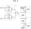
- FIG. 3 is a diagram for illustrating a phase relationship between differential signals in a Q-channel in the first embodiment.
- the phase and amplitude of the eleventh signal are represented by a vector diagram indicated by reference symbol B of FIG. 3 .
- the vector diagram an "upper local” case and a “lower local” case are each illustrated.
- the phases and amplitudes of the ninth signal, the tenth signal, and the eleventh signal are as follows.
- FIG. 4 is a diagram for illustrating a phase relationship between differential signals that have been combined in the first embodiment.
- the phases and amplitudes of the sixth signal and the eleventh signal at the first output terminal 14 are represented by a vector diagram indicated by reference symbol C of FIG. 4 .
- an "upper local” case and a “lower local” case are each illustrated.
- the phases and amplitudes of the sixth signal and the eleventh signal are as follows. ⁇ Upper Local> Signal Phase Amplitude Sixth signal 45° V I ' Eleventh signal 135° V Q ' ⁇ Lower Local> Signal Phase Amplitude Sixth signal 315° V I ' Eleventh signal 225° V Q '
- the mixer according to the first embodiment illustrated in FIG. 1 operates as a quadrature mixer.
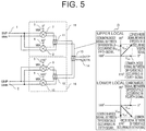
- FIG. 5 is a diagram for illustrating a phase relationship between common-mode signals in the I-channel in the first embodiment.
- the amplitudes of common-mode signals between differentials occurring in the fourth signal and the fifth signal are both set as V cm and the amplitude of a common-mode signal between differentials occurring in the sixth signal is set as V cm '
- the phase and amplitude of the common-mode signal between the differentials occurring in the sixth signal is represented by a vector diagram indicated by reference symbol D of FIG. 5 .
- an "upper local” case and a “lower local” case are each illustrated.
- phase Amplitude Common-mode signal between differentials occurring in the fourth signal, the common-mode signal between the differentials occurring in the fifth signal, and the common-mode signal between the differentials occurring in the sixth signal are as follows. ⁇ Upper Local> Signal Phase Amplitude Common-mode signal between differentials occurring in fourth signal 0° V cm Common-mode signal between differentials occurring in fifth signal 90° V cm Common-mode signal between differentials occurring in sixth signal 45° V cm ' ⁇ Lower Local> Signal Phase Amplitude Common-mode signal between differentials occurring in fourth signal 0° V cm Common-mode signal between differentials occurring in fifth signal 270° V cm Common-mode signal between differentials occurring in sixth signal 315° V cm '
- FIG. 6 is a diagram for illustrating a phase relationship between common-mode signals in the Q-channel in the first embodiment.
- the amplitudes of common-mode signals between differentials occurring in the ninth signal and the tenth signal are both set as V cm and the amplitude of a common-mode signal between differentials occurring in the eleventh signal is set as V cm '
- the phase and amplitude of the common-mode signal between the differentials occurring in the eleventh signal is represented by a vector diagram indicated by reference symbol E of FIG. 6 .
- an "upper local” case and a "lower local” case are each illustrated.
- phase Amplitude Common-mode signal between differentials occurring in the ninth signal, the common-mode signal between the differentials occurring in the tenth signal, and the common-mode signal between the differentials occurring in the eleventh signal are as follows. ⁇ Upper Local> Signal Phase Amplitude Common-mode signal between differentials occurring in ninth signal 270° V cm Common-mode signal between differentials occurring in tenth signal 180° V cm Common-mode signal between differentials occurring in eleventh signal 225° V cm ' ⁇ Lower Local> Signal Phase Amplitude Common-mode signal between differentials occurring in ninth signal 90° V cm Common-mode signal between differentials occurring in tenth signal 180° V cm Common-mode signal between differentials occurring in eleventh signal 135° V cm '
- FIG. 7 is a diagram for illustrating a phase relationship between common-mode signals that have been combined in the first embodiment.
- the phases and amplitudes of the sixth signal and the eleventh signal at the first output terminal 14 are represented by a vector diagram indicated by reference symbol F of FIG. 7 .
- an "upper local” case and a “lower local” case are each illustrated.
- the phases and amplitudes of the sixth signal and the eleventh signal are as follows. ⁇ Upper Local> Signal Phase Amplitude Sixth signal 45° V cm ' Eleventh signal 225° V cm ' ⁇ Lower Local> Signal Phase Amplitude Sixth signal 315° V cm ' Eleventh signal 135° V cm '
- the common-mode signal in the I channel and the common-mode signal in the Q channel are combined so as to have the same amplitude and opposite phases, and hence the common-mode signals are canceled.
- the quadrature mixers 15 and 16 are formed of the four unit mixers 7 to 10 having the same configuration. Further, the first LO wave oscillator and the second LO wave oscillator that differ in phase by 180° are used to input the quadrature-phase LO waves having phase differences of 90° to those four unit mixers, namely, the first unit mixer 7, the second unit mixer 8, the third unit mixer 9, and the fourth unit mixer 10, respectively. Further, the first combiner 13, the second combiner 11, and the third combiner 12 are provided, and hence the output signals from the first quadrature mixer 15 and the second quadrature mixer 16 are combined to cancel the common-mode signal components as illustrated in FIG. 7 .
- the output of the first quadrature mixer 15 operating with the LO waves of 0° and 90° and the output of the second quadrature mixer 16 operating with the LO waves of 180° and 270° being the LO waves of the phases opposite to those of the first quadrature mixer 15 are combined to cancel the output signals.
- the differential signals and the common-mode signals are both canceled, and hence, in the first embodiment, only one differential terminal is inverted to be connected to the third combiner 12. With this configuration, the polarity of the differential signal is inverted before and after the portion at which the differential terminal is inverted, and the polarity of the common-mode signal remains the same.
- the baseband signal terminal may be single-phase.
- the mixer according to the first embodiment can also be configured to operate as an image rejection mixer. That is, a third input signal is input to the 90° phase difference splitting unit.
- the 90° phase difference splitting unit generates the first input signal to be input to the first input terminal 1 and the second signal to be input to the second input terminal 2 from the third input signal.
- the 90° phase difference splitting unit may be formed of, for example, a 90° phase difference splitter and a 90° phase shifter, or may be formed of an in-phase splitter and a 90° phase shifter.
- FIG. 8 is a diagram for illustrating one configuration example of a mixer according to a second embodiment of the present invention.
- a mixer to be used as a mixer for transmission is described as an example, but the embodiments are not limited thereto.
- the mixer according to the second embodiment includes a first input terminal 17, a second input terminal 18, a first quadrature mixer 31, a second quadrature mixer 32, a first combiner 29 configured to combine an output signal from the first quadrature mixer 31 and an output signal from the second quadrature mixer 32, and a first output terminal 30.
- the first quadrature mixer 31 includes a first unit mixer 23, a second unit mixer 24, and a second combiner 27.
- the first unit mixer 23 includes a baseband signal terminal and an RF signal terminal, and also includes a first LO input terminal 19 configured to receive input of an LO wave of 0° serving as a first LO wave.
- the baseband signal terminal and the RF signal terminal of the first unit mixer 23 are each formed of a differential terminal.
- the second unit mixer 24 includes a baseband signal terminal and an RF signal terminal, and also includes a second LO input terminal 20 configured to receive input of an LO wave of 90° serving as a second LO wave.
- the baseband signal terminal and the RF signal terminal of the second unit mixer 24 are each formed of a differential terminal.
- the second combiner 27 is configured to combine an output signal from the first unit mixer 23 and an output signal from the second unit mixer 24.
- the first LO wave and the second LO wave are each input from a first LO wave oscillator (not shown).
- the first LO wave oscillator is formed of, for example, a quadrature oscillator.
- the baseband signal terminal and the RF signal terminal are described as being both formed of differential terminals as an example, but are not limited to that case, and it suffices that at least one of the baseband signal terminal and the RF signal terminal is formed of a differential terminal.
- the first unit mixer 23 and the second unit mixer 24 have the same configuration.
- the LO waves to be supplied to the first unit mixer 23 and the second unit mixer 24 are described by taking the case of the phases being 0° and 90°, respectively, but are not limited to that case, and no particular limitations are imposed on the phases as long as the LO waves are orthogonal to each other.
- the second quadrature mixer 32 includes a third unit mixer 25, a fourth unit mixer 26, and a third combiner 28.
- the third unit mixer 25 includes a baseband signal terminal and an RF signal terminal, and also includes a third LO input terminal 21 configured to receive input of an LO wave of 270° serving as a third LO wave.
- the baseband signal terminal and the RF signal terminal of the third unit mixer 25 are each formed of a differential terminal.
- the baseband signal terminal of the third unit mixer 25 is connected to the second input terminal 18 with the polarity being inverted.
- the fourth unit mixer 26 includes a baseband signal terminal and an RF signal terminal, and also includes a fourth LO input terminal 22 configured to receive input of an LO wave of 180° serving as a fourth LO wave.
- the baseband signal terminal and the RF signal terminal of the fourth unit mixer 26 are each formed of a differential terminal.
- the third combiner 28 is configured to combine an output signal from the third unit mixer 25 and an output signal from the fourth unit mixer 26.
- the third LO wave and the fourth LO wave are each input from a second LO wave oscillator (not shown).
- the second LO wave oscillator is formed of, for example, a quadrature oscillator.
- the baseband signal terminal and the RF signal terminal are described as being both formed of differential terminals as an example, but are not limited to that case, and it suffices that at least one of the baseband signal terminal and the RF signal terminal is formed of a differential terminal.
- the third unit mixer 25 and the fourth unit mixer 26 have the same configuration.
- the first to fourth unit mixers 23 to 26 are described as all having the same configuration.
- the LO waves to be supplied to the third unit mixer 25 and the fourth unit mixer 26 are described by taking the case of the phases being 270° and 180°, respectively, but are not limited to that case, and no particular limitations are imposed on the phases as long as the LO waves are orthogonal to each other.
- the LO wave to be oscillated from the first LO wave oscillator and the LO wave to be oscillated from the second LO wave oscillator differ in phase by 180°.
- the LO wave to be input to the first unit mixer 23 and the LO wave to be input to the fourth unit mixer 26 are described as differing in phase by 180°, but the LO wave to be input to the first unit mixer 23 and the LO wave to be input to the third unit mixer 25 may be set to differ in phase by 180°.
- the LO wave to be input to the second unit mixer 24 and the LO wave to be input to the third unit mixer 25 are described as differing in phase by 180°, but the LO wave to be input to the second unit mixer 24 and the LO wave to be input to the fourth unit mixer 26 may be set to differ in phase by 180°.
- a first input signal input to the first input terminal 17 is in-phase-distributed into a second signal and a third signal to be input to the first quadrature mixer 31.
- the second signal is input to the baseband signal terminal of the first unit mixer 23, and the third signal is input to the baseband signal terminal of the second unit mixer 24.
- the first unit mixer 23 multiplies the second signal and the LO wave of 0° input from the first LO input terminal 19 to output a fourth signal from the RF signal terminal.
- the second unit mixer 24 multiplies the third signal and the LO wave of 90° input from the second LO input terminal 20 to output a fifth signal from the RF signal terminal.
- the second combiner 27 combines the fourth signal and the fifth signal to output a sixth signal.
- a second input signal input to the second input terminal 18 is in-phase-distributed into a seventh signal and an eighth signal to be input to the second quadrature mixer 32.
- the seventh signal is input to the baseband signal terminal of the third unit mixer 25, and the eighth signal is input to the baseband signal terminal of the fourth unit mixer 26.
- the third unit mixer 25 multiplies the seventh signal and the LO wave of 270° input from the third LO input terminal 21 to output a ninth signal from the RF signal terminal.
- the baseband signal terminal of the third unit mixer 25 is connected to the second input terminal 18 with the polarity being inverted as illustrated in FIG. 8 . Therefore, the seventh signal is input to the baseband signal terminal of the third unit mixer 25 with the polarity being inverted.
- the fourth unit mixer 26 multiplies the eighth signal and the LO wave of 180° input from the fourth LO input terminal 22 to output a tenth signal from the RF signal terminal.
- the third combiner 28 combines the ninth signal and the tenth signal to output an eleventh signal.
- the first combiner 29 combines the sixth signal and the eleventh signal to output the combined signal from the first output terminal 30 to the outside.
- the quadrature mixers 31 and 32 are formed of the four unit mixers 23 to 26 having the same configuration.
- the quadrature-phase LO waves having phase differences of 90°, namely, the LO waves of 0°, 90°, 180°, and 270° are used for those four unit mixers, namely, the first unit mixer 23, the second unit mixer 24, the third unit mixer 25, and the fourth unit mixer 26, respectively.
- the first combiner 29, the second combiner 27, and the third combiner 28 are provided, and hence the output signals from the first quadrature mixer 31 and the second quadrature mixer 32 are combined.
- the input of the third unit mixer 25 configured to input the LO wave of 270° is connected to the second input terminal 18 at the previous stage with the polarity being inverted.
- the second embodiment and the first embodiment are different in that in the first embodiment, the RF signal terminal of the third unit mixer 9 is formed of a differential terminal and connected to the third combiner 12 at the subsequent stage with the differential terminal being inverted, while in the second embodiment, the baseband signal terminal of the third unit mixer 25 is formed of a differential terminal and connected to the second input terminal 18 at the previous stage with the differential terminal being inverted.
- the configurations of the first quadrature mixer 31, the second quadrature mixer 32, the first combiner 29, the first unit mixer 23, the second unit mixer 24, the third unit mixer 25, the fourth unit mixer 26, the second combiner 27, and the third combiner 28 which are illustrated in FIG. 8 are merely examples, and are not limited thereto, and it is to be understood that components having other configurations may be used.
- the three combiners 27 to 29 are provided, but one combiner may be configured to combine the outputs of the four unit mixers 23 to 26.
- FIG. 9 is a diagram for illustrating a phase relationship between differential signals in an I-channel in the second embodiment.
- the phase and amplitude of the sixth signal are represented by a vector diagram indicated by reference symbol G of FIG. 9 .
- the vector diagram an "upper local” case and a “lower local” case are each illustrated.
- the phases and amplitudes of the fourth signal, the fifth signal, and the sixth signal are as follows.
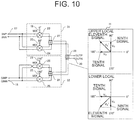
- FIG. 10 is a diagram for illustrating a phase relationship between differential signals in a Q-channel in the second embodiment.
- the phase and amplitude of the eleventh signal are represented by a vector diagram indicated by reference symbol H of FIG. 10 .
- the vector diagram an "upper local” case and a "lower local” case are each illustrated.
- the phases and amplitudes of the ninth signal, the tenth signal, and the eleventh signal are as follows.
- FIG. 11 is a diagram for illustrating a phase relationship between differential signals that have been combined in the second embodiment.
- the phases and amplitudes of the sixth signal and the eleventh signal at the first output terminal 30 are represented by a vector diagram indicated by reference symbol J of FIG. 11 .
- an "upper local” case and a “lower local” case are each illustrated.
- the phases and amplitudes of the sixth signal and the eleventh signal are as follows. ⁇ Upper Local> Signal Phase Amplitude Sixth signal 45° V I ' Eleventh signal 135° V Q ' ⁇ Lower Local> Signal Phase Amplitude Sixth signal 315° V I ' Eleventh signal 225° V Q '
- the mixer according to the second embodiment operates as a quadrature mixer.
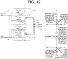
- FIG. 12 is a diagram for illustrating a phase relationship between common-mode signals in the I-channel in the second embodiment.
- the amplitudes of common-mode signals between differentials occurring in the fourth signal and the fifth signal are both set as V cm and the amplitude of a common-mode signal between differentials occurring in the sixth signal is set as V cm '
- the phase and amplitude of the common-mode signal between the differentials occurring in the sixth signal is represented by a vector diagram indicated by reference symbol K of FIG. 12 .
- an "upper local” case and a “lower local” case are each illustrated.
- phase Amplitude Common-mode signal between differentials occurring in the fourth signal, the common-mode signal between the differentials occurring in the fifth signal, and the common-mode signal between the differentials occurring in the sixth signal are as follows. ⁇ Upper Local> Signal Phase Amplitude Common-mode signal between differentials occurring in fourth signal 0° V cm Common-mode signal between differentials occurring in fifth signal 90° V cm Common-mode signal between differentials occurring in sixth signal 45° V cm ' ⁇ Lower Local> Signal Phase Amplitude Common-mode signal between differentials occurring in fourth signal 0° V cm Common-mode signal between differentials occurring in fifth signal 270° V cm Common-mode signal between differentials occurring in sixth signal 315° V cm '
- FIG. 13 is a diagram for illustrating a phase relationship between common-mode signals in the Q-channel in the second embodiment.
- the amplitudes of common-mode signals between differentials occurring in the ninth signal and the tenth signal are both set as V cm and the amplitude of a common-mode signal between differentials occurring in the eleventh signal is set as V cm '
- the phase and amplitude of the common-mode signal between the differentials occurring in the eleventh signal is represented by a vector diagram indicated by reference symbol L of FIG. 13 .
- an "upper local” case and a "lower local” case are each illustrated.
- phase Amplitude Common-mode signal between differentials occurring in the ninth signal, the common-mode signal between the differentials occurring in the tenth signal, and the common-mode signal between the differentials occurring in the eleventh signal are as follows. ⁇ Upper Local> Signal Phase Amplitude Common-mode signal between differentials occurring in ninth signal 270° V cm Common-mode signal between differentials occurring in tenth signal 180° V cm Common-mode signal between differentials occurring in eleventh signal 225° V cm ' ⁇ Lower Local> Signal Phase Amplitude Common-mode signal between differentials occurring in ninth signal 90° V cm Common-mode signal between differentials occurring in tenth signal 180° V cm Common-mode signal between differentials occurring in eleventh signal 135° V cm '
- FIG. 14 is a diagram for illustrating a phase relationship between common-mode signals that have been combined in the second embodiment.
- the phases and amplitudes of the sixth signal and the eleventh signal at the first output terminal 30 are represented by a vector diagram indicated by reference symbol M of FIG. 14 .
- an "upper local” case and a “lower local” case are each illustrated.
- the phases and amplitudes of the sixth signal and the eleventh signal are as follows. ⁇ Upper Local> Signal Phase Amplitude Sixth signal 45° V cm ' Eleventh signal 225° V cm ' ⁇ Lower Local> Signal Phase Amplitude Sixth signal 315° V cm ' Eleventh signal 135° V cm '
- the common-mode signal in the I channel and the common-mode signal in the Q channel are combined so as to have the same amplitude and opposite phases, and hence the common-mode signals are canceled.
- FIG. 15 is a diagram for illustrating a phase relationship between LO leaks in the I-channel in the second embodiment.
- the phases and amplitudes of the LO leak occurring in the first unit mixer 23, the LO leak occurring in the second unit mixer 24, and the LO leak occurring at the output terminal of the second combiner 27 are as follows. Signal Phase Amplitude LO leak occurring in first unit mixer 23 0° V LO LO leak occurring in second unit mixer 24 90° V LO LO leak occurring at output terminal of second combiner 27 45° V LO '
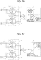
- FIG. 16 is a diagram for illustrating a phase relationship between LO leaks in the Q-channel in the second embodiment.
- the amplitudes of the LO leaks occurring in the third unit mixer 25 and the fourth unit mixer 26 are both set as V LO and the amplitude of the LO leak occurring at the output terminal of the third combiner 28 is set as V LO '
- the phases and amplitudes of the LO leak occurring at the output terminal of the third combiner 28 is represented by a vector diagram indicated by reference symbol P of FIG. 16 .
- an "upper local” case and a "lower local” case are each illustrated.
- the phases and amplitudes of the LO leak occurring in the third unit mixer 25, the LO leak occurring in the fourth unit mixer 26, and the LO leak occurring at the output terminal of the third combiner 28 are as follows.
- FIG. 17 is a diagram for illustrating a phase relationship between LO leaks that have been combined in the second embodiment.
- the phases and amplitudes of the LO leak occurring at the output terminal of the second combiner 27 and the LO leak occurring at the output terminal of the third combiner 28 at the first output terminal 30 is represented by a vector diagram indicated by reference symbol R of FIG. 17 .
- R of FIG. 17 In the vector diagram, an "upper local” case and a “lower local” case are each illustrated.
- the phases and amplitudes of the LO leak occurring at the output terminal of the second combiner 27 and the LO leak occurring at the output terminal of the third combiner 28 are as follows.
- Signal Phase Amplitude LO leak occurring at output terminal of the second combiner 27 45° V LO ' LO leak occurring at output terminal of the third combiner 28 225° V LO '
- the LO leak in the I-channel and the LO leak in the Q-channel are combined so as to have the same amplitude and opposite phases, and hence the LO leaks are canceled.
- the first quadrature mixer 31 and the second quadrature mixer 32 are formed of the four unit mixers 23 to 26 having the same configuration. Further, through use of the first LO wave oscillator and the second LO wave oscillator that differ in phase by 180°, the quadrature-phase LO waves having phase differences of 90° are used for those four unit mixers, namely, the first unit mixer 23, the second unit mixer 24, the third unit mixer 25, and the fourth unit mixer 26, respectively. Further, the first combiner 29, the second combiner 27, and the third combiner 28 are provided, and hence the output signals from the first quadrature mixer 31 and the second quadrature mixer 32 are combined to cancel the common-mode signal components.
- the output of the first quadrature mixer 31 operating with the LO waves of 0° and 90° and the output of the second quadrature mixer 32 operating with the LO waves of 180° and 270° being the LO waves of the phases opposite to those of the first quadrature mixer 31 are combined to cancel the output signals.
- the differential signals and the common-mode signals are both canceled, and hence, in the second embodiment, only one differential terminal is inverted to be connected to the second input terminal 18.
- the mixer according to the second embodiment can also be configured to operate as an image rejection mixer.
- the third input signal is input to the 90° phase difference splitting unit.
- the 90° phase difference splitting unit generates the first input signal to be input to the first input terminal 17 and the second signal to be input to the second input terminal 18 from the third input signal.
- the 90° phase difference splitting unit may be formed of, for example, a 90° phase difference splitter and a 90° phase shifter, or may be formed of an in-phase splitter and a 90° phase shifter.
- FIG. 18 is a diagram for illustrating one configuration example of a mixer according to a third embodiment of the present invention.
- the mixer according to the third embodiment includes a first input terminal 33, a second input terminal 34, a first mixer 45, a first output terminal 46, a first quadrature mixer 47, a second quadrature mixer 48, and a feedback circuit 59.
- the first quadrature mixer 47 includes a first unit mixer 39, a second unit mixer 40, and a second combiner 43.
- the first unit mixer 39 includes a baseband signal terminal, an RF signal terminal, a first LO input terminal 35, and a first LO leak control terminal 49.
- the baseband signal terminal and the RF signal terminal of the first unit mixer 39 are each formed of a differential terminal.
- the LO wave having the phase of 0° is input to the first LO input terminal 35 as a first LO wave.
- a signal for controlling the amplitude and polarity of an LO leak is input to the first LO leak control terminal 49.
- the second unit mixer 40 includes a baseband signal terminal, an RF signal terminal, a second LO input terminal 36, and a second LO leak control terminal 50.
- the baseband signal terminal and the RF signal terminal of the second unit mixer 40 are each formed of a differential terminal.
- the LO wave having the phase of 90° is input to the second LO input terminal 36 as a second LO wave.
- a signal for controlling the amplitude and polarity of an LO leak is input to the second LO leak control terminal 50.
- the second combiner 43 is configured to combine the output signal from the first unit mixer 39 and the output signal from the second unit mixer 40. Both the first LO wave and the second LO wave are oscillated from a first LO wave oscillator (not shown).
- the first LO wave oscillator is, for example, a quadrature oscillator.
- the second quadrature mixer 48 includes a third unit mixer 41, a fourth unit mixer 42, and a third combiner 44.
- the third unit mixer 41 includes a baseband signal terminal, an RF signal terminal, and a third LO input terminal 37.
- the baseband signal terminal and the RF signal terminal of the third unit mixer 41 are each formed of a differential terminal.
- the LO wave having the phase of 270° is input to the third LO input terminal 37 as a third LO wave.
- the baseband signal terminal of the third unit mixer 41 is connected to the second input terminal 34 with its polarity being inverted.
- a terminal on the positive phase side of the baseband signal terminal is connected to a terminal on the negative phase side of the second input terminal 34
- a terminal on the negative phase side of the baseband signal terminal is connected to a terminal on the positive phase side of the second input terminal 34.
- the fourth unit mixer 42 includes a baseband signal terminal, an RF signal terminal, and a fourth LO input terminal 38.
- the baseband signal terminal and the RF signal terminal of the fourth unit mixer 42 are each formed of a differential terminal.
- the LO wave having the phase of 180° is input to the fourth LO input terminal 38 as a fourth LO wave.
- the third combiner 44 is configured to combine the output signal from the third unit mixer 41 and the output signal from the fourth unit mixer 42. Both the third LO wave and the fourth LO wave are oscillated from a second LO wave oscillator (not shown).
- the second LO wave oscillator is, for example, a quadrature oscillator.
- a first input signal input to the first input terminal 33 is in-phase-distributed into a second signal and a third signal to be input to the first quadrature mixer 47.
- the second signal is input to the baseband signal terminal of the first unit mixer 39, and the third signal is input to the baseband signal terminal of the second unit mixer 40.
- a second input signal input to the second input terminal 34 is in-phase-distributed into a seventh signal and an eighth signal to be input to the second quadrature mixer 48.
- the seventh signal is input to the baseband signal terminal of the third unit mixer 41, and the eighth signal is input to the baseband signal terminal of the fourth unit mixer 42.
- the first combiner 45 is configured to combine the output signal from the first quadrature mixer 47 and the output signal from the second quadrature mixer 48 and to output the combined signal to the first output terminal 46.
- the feedback circuit 59 includes an amplifier 51, a first bias control circuit 56, a second bias control circuit 57, and a third quadrature mixer 58.
- the amplifier 51 includes a differential input terminal and a differential output terminal.
- the amplifier 51 is an amplifier of a gain Ga.
- the input terminal of the amplifier 51 is connected to the first combiner 45.
- the output terminal of the amplifier 51 is connected to the third quadrature mixer 58.
- the first bias control circuit 56 includes a differential input terminal and a differential output terminal.
- the second bias control circuit 57 includes a differential input terminal and a differential output terminal. However, in FIG. 18 , those differential output terminals are each simplified and represented as a single-phase output terminal.
- the first bias control circuit 56 and the second bias control circuit 57 each include analog circuits, for example, an operational amplifier and a transistor.
- the output terminal of the first bias control circuit 56 is connected to the first LO leak control terminal 49 of the first unit mixer 39.
- the first LO leak control terminal 49 is a differential input terminal.
- the output terminal of the second bias control circuit 57 is connected to the second LO leak control terminal 50 of the second unit mixer 40.
- the second LO leak control terminal 50 is a differential input terminal.
- the first LO leak control terminal 49 and the second LO leak control terminal 50 are each simplified and represented as a single-phase input terminal.
- the third quadrature mixer 58 includes a fifth unit mixer 52 and a sixth unit mixer 53.
- the fifth unit mixer 52 includes a fifth RF signal terminal, a fifth LO input terminal 54, and a fifth baseband signal terminal.
- the fifth RF signal terminal and the fifth baseband signal terminal are each a differential terminal.
- a fifth LO wave having the same phase as that of the first LO wave is input to the fifth LO input terminal 54. That is, the LO wave having the phase of 0° is input to the fifth LO input terminal 54 as a fifth LO wave.
- the fifth baseband signal terminal is configured to output a signal obtained by multiplying a signal input to the fifth RF signal terminal and the fifth LO wave input to the fifth LO input terminal 54.
- the sixth unit mixer 53 includes a sixth RF signal terminal, a sixth LO input terminal 55, and a sixth baseband signal terminal.
- the sixth RF signal terminal and the sixth baseband signal terminal are each a differential terminal.
- a sixth LO wave having the same phase as that of the second LO wave is input to the sixth LO input terminal 55. That is, the LO wave having the phase of 90° is input to the sixth LO input terminal 55 as a sixth LO wave.
- the sixth baseband signal terminal is configured to output a signal obtained by multiplying a signal input to the sixth RF signal terminal and the sixth LO wave input to the sixth LO input terminal 55.
- Both the fifth LO wave and the sixth LO wave are oscillated from a third LO wave oscillator (not shown).
- the third LO wave oscillator is, for example, a quadrature oscillator.
- a signal output from the output terminal of the amplifier 51 is in-phase-distributed into the fifth RF signal terminal and the sixth RF signal terminal. That is, a signal from the first combiner 45 is input to the fifth RF signal terminal through the amplifier 51. In the same manner, the signal from the first combiner 45 is input to the sixth RF signal terminal through the amplifier 51.
- the fifth baseband signal terminal is connected to the input terminal of the first bias control circuit 56.
- the sixth baseband signal terminal is connected to the input terminal of the second bias control circuit 57.
- the amplifier 51 is provided between the fifth unit mixer 52 and sixth unit mixer 53 and the first combiner 45.
- the amplifier 51 is configured to pass therethrough a signal from the output terminal of the first combiner 45 toward the fifth RF signal terminal and a signal from the output terminal of the first combiner 45 toward the sixth RF signal terminal.
- the amplifier 51 is configured to cut off a signal from the fifth RF signal terminal toward the output terminal of the first combiner 45 and the signal from the sixth RF signal terminal toward the output terminal of the first combiner 45. That is, the amplifier 51 can be referred to as a directional device.
- FIG. 20 is a diagram for illustrating one configuration example of the first unit mixer 39 according to the third embodiment. As illustrated in FIG. 20 , the first unit mixer 39 is a differential double-balanced mixer of a Gilbert cell type.
- a pair of baseband signal terminals 60 of FIG. 20 correspond to the baseband signal terminal of the first unit mixer 39.
- a pair of LO leak control terminals 62 of FIG. 20 namely, “BIASP” and “BIASN” correspond to the first LO leak control terminal 49.
- a pair of LO input terminals 63 of FIG. 20 namely, "LOINP” and “LOINN” correspond to the first LO input terminal 35.
- a pair of RF signal terminals 72 of FIG. 20 namely, "RFOUTP” and “RFOUTN” correspond to the RF signal terminal of the first unit mixer 39.
- a DC component of an input signal is cut off by a capacitor 61.
- base voltages of a pair of bipolar transistors 64 and 65 are independently controlled by the differential bias voltages input from the pair of LO leak control terminals 62. That is, a DC component of a positive phase signal of a baseband signal and a DC component of a negative phase signal of the baseband signal are controlled independently.
- An LO leak occurs due to frequency conversion of the DC component of the baseband signal. Therefore, the amplitude and polarity of the positive phase signal of an LO leak and the amplitude and polarity of the negative phase signal of the LO leak are controlled independently of each other.
- the second unit mixer 40 has the same configuration as that of the first unit mixer 39.
- the configuration of the mixer according to the third embodiment is a configuration in which the feedback circuit 59 is added to the mixer according to the second embodiment. Further, the output terminal of the first bias control circuit 56 is connected to the first LO leak control terminal 49, and the output terminal of the second bias control circuit 57 is connected to the second LO leak control terminal 50. That is, the configuration of the mixer is the same as that of the second embodiment except that the feedback circuit 59 is added and that the first unit mixer 39 and the second unit mixer 40 include the first LO leak control terminal 49 and the second LO leak control terminal 50, respectively.
- the LO leak occurs when each LO wave leaks from the LO input terminal of each unit mixer to the RF signal terminal.
- the LO leak may also occur due to an imbalance of a differential circuit in each unit mixer due to manufacturing variations of each unit mixer.
- the first unit mixer 39 outputs a first LO leak from the RF signal terminal of the first unit mixer 39.
- the second unit mixer 40 outputs a second LO leak from the RF signal terminal of the second unit mixer 40.
- the third unit mixer 41 outputs a third LO leak from the RF signal terminal of the third unit mixer 41.
- the fourth unit mixer 42 outputs a fourth LO leak from the RF signal terminal of the fourth unit mixer 42.
- the second combiner 43 combines the first LO leak and the second LO leak to output a fifth LO leak.
- the third combiner 44 combines the third LO leak and the fourth LO leak to output a sixth LO leak.
- the first combiner 45 combines the fifth LO leak and the sixth LO leak.
- the LO leak combined by the first combiner 45 is in-phase-distributed into a seventh LO leak and an eighth LO leak.
- the seventh LO leak is output to the amplifier 51.
- the eighth LO leak is output to the outside from the first output terminal 46.
- the amplifier 51 amplifies the seventh LO leak to output the amplified seventh LO leak as a ninth LO leak.
- the ninth LO leak is input to the third quadrature mixer 58 to be in-phase-distributed into a tenth LO leak and an eleventh LO leak.
- the tenth LO leak is input to the RF signal terminal of the fifth unit mixer 52.
- the eleventh LO leak is input to the RF signal terminal of the sixth unit mixer 53.
- the fifth unit mixer 52 multiplies the LO wave having the phase of 0° input from the fifth LO input terminal 54 and the tenth LO leak to output a twelfth signal from the baseband signal terminal of the fifth unit mixer 52.
- the sixth unit mixer 53 multiplies the LO wave having the phase of 90° input from the sixth LO input terminal 55 and the eleventh LO leak to output a thirteenth signal from the baseband signal terminal of the sixth unit mixer 53.
- the first bias control circuit 56 outputs a first bias voltage V B1 corresponding to the magnitude of the input twelfth signal, namely, the signal output from the fifth baseband signal terminal.
- the second bias control circuit 57 outputs a second bias voltage V B2 corresponding to the magnitude of the input thirteenth signal, namely, the signal output from the sixth baseband signal terminal.
- the first bias voltage V B1 is input to the first LO leak control terminal 49 of the first unit mixer 39.
- the second bias voltage V B2 is input to the second LO leak control terminal 50 of the second unit mixer 40.
- FIG. 19 is a diagram for illustrating LO leaks in the mixer according to the third embodiment.
- no signal is input to each of the first input terminal 33 and the second input terminal 34.
- Reference symbol V LO1 denotes a first LO leak occurring from the first unit mixer 39.
- Reference symbol V LO2 denotes a second LO leak occurring from the second unit mixer 40.
- Reference symbol V LO3 denotes a third LO leak occurring from the third unit mixer 41.
- Reference symbol V LO4 denotes a fourth LO leak occurring from the fourth unit mixer 42.
- Reference symbol V LOOUT denotes a seventh LO leak after being combined by the first combiner 45.
- Reference symbol V cont1 denotes a signal in which the LO leak V LOOUT is down-converted by the fifth unit mixer 52, and corresponds to a twelfth LO leak.
- Reference symbol V cont2 denotes a signal in which the LO leak V LOOUT is down-converted by the sixth unit mixer 53, and corresponds to a thirteenth LO leak.
- the LO wave having the phase of 0° is denoted by cos ⁇ t
- the LO wave having the phase of 90° is denoted by sin ⁇ t
- the LO wave having the phase of 180° is denoted by - cos ⁇ t
- the LO wave having the phase of 270° is denoted by - sin ⁇ t.
- the amplitude of the first LO leak V LO1, the amplitude of the second LO leak V LO2 , the amplitude of the third LO leak V LO3 , and the amplitude of the fourth LO leak V LO4 are set as ⁇ V 1 , ⁇ V 2 , ⁇ V 3 , and ⁇ V 4 , respectively.
- the first LO leak V LO1 , the second LO leak V LO2 , the third LO leak V LO3 , and the fourth LO leak V LO4 are expressed by Expression (1) to Expression (4), respectively.
- V LO1 ⁇ V 1 ⁇ cos ⁇ t
- V LO2 ⁇ V 2 ⁇ sin ⁇ t
- V LO3 ⁇ ⁇ V 3 ⁇ sin ⁇ t
- V LO4 ⁇ ⁇ V 4 ⁇ cos ⁇ t
- V LOOUT ⁇ V 1 ⁇ ⁇ V 4 ⁇ cos ⁇ t + ⁇ V 2 ⁇ ⁇ V 3 ⁇ sin ⁇ t
- the first bias control circuit 56 outputs the first bias voltage V B1 corresponding to the magnitude of the twelfth LO leak V cont1 to the first LO leak control terminal 49.
- the DC component of the baseband signal is controlled to change the amplitude ⁇ V 1 and polarity of the first LO leak V LO1 .
- the second bias control circuit 57 outputs the second bias voltage V B2 corresponding to the magnitude of the thirteenth LO leak V cont2 to the second LO leak control terminal 50.
- the DC component of the baseband signal is controlled to change the amplitude ⁇ V 2 and polarity of the second LO leak V LO2 .
- a correspondence relationship between the magnitude of the twelfth LO leak V cont1 and the first bias voltage V B1 is set in advance so that the feedback control of the feedback circuit 59 becomes negative feedback control.
- a correspondence relationship between the magnitude of the thirteenth LO leak V cont2 and the second bias voltage V B2 is set in advance so that the feedback control of the feedback circuit 59 becomes negative feedback control.
- the twelfth LO leak V cont1 and the first bias voltage V B1 are associated with each other in advance so that the amplitude ⁇ V 1 of the first LO leak becomes closer to the amplitude ⁇ V 4 of the fourth LO leak.
- the thirteenth LO leak V cont2 and the second bias voltage V B2 are associated with each other in advance so that the amplitude ⁇ V 2 of the second LO leak becomes closer to the amplitude ⁇ V 3 of the third LO leak. Therefore, with this feedback control, the twelfth LO leak V cont1 and the thirteenth LO leak V cont2 each converge to 0, and the seventh LO leak V LOOUT converges to 0.
- the amplitude ⁇ V 1 of the first LO leak V LO1 and the amplitude ⁇ V 4 of the fourth LO leak V LO4 are equal, and the phase of the first LO leak V LO1 and the phase of the fourth LO leak V LO4 are opposite in phase.
- the amplitude ⁇ V 2 of the second LO leak V LO2 and the amplitude ⁇ V 3 of the third LO leak V LO3 are equal, and the phase of the second LO leak V LO2 and the phase of the third LO leak V LO3 are opposite in phase.
- the feedback circuit 59 corrects the LO leaks due to the manufacturing variations of the first unit mixer 39, the second unit mixer 40, the third unit mixer 41, and the fourth unit mixer 42.
- the mixer according to the third embodiment operates the feedback circuit 59 when the first input signal is not input to the first input terminal 33 and the second input signal is not input to the second input terminal 34.
- the mixer according to the third embodiment corrects the LO leak due to the manufacturing variations of each unit mixer by the feedback control of the feedback circuit 59. After the LO leaks are corrected, the mixer according to the third embodiment determines the first bias voltage V B1 as a first reference voltage, and determines the second bias voltage V B2 as a second reference voltage.
- the mixer according to the third embodiment stops the operation of the feedback circuit 59 when the first input signal is input to the first input terminal 33 and the second input signal is input to the second input terminal 34.
- the mixer according to the third embodiment sets an output voltage from the first bias control circuit 56 as the first reference voltage, and sets an output voltage from the second bias control circuit 57 as the second reference voltage.
- the first bias voltage V B1 is held at the first reference voltage after the LO leaks due to the manufacturing variations of each unit mixer are corrected.
- the second bias voltage V B2 is held at the second reference voltage.
- the mixer according to the third embodiment can suppress not only the LO leaks due to the leakage of the LO wave and the common-mode signals between the differential terminals but also the LO leak due to the manufacturing variations of each unit mixer.
- the baseband signal terminal of the third unit mixer 41 is connected to the second input terminal 34 with its polarity being inverted.
- the terminal having the polarity inverted may be the baseband signal terminal of the first unit mixer 39, the baseband signal terminal of the second unit mixer 40, or the baseband signal terminal of the fourth unit mixer 42.
- all the RF terminals of the first unit mixer 39, the second unit mixer 40, the third unit mixer 41, the fourth unit mixer 42, the fifth unit mixer 52, and the sixth unit mixer 53 may be single-phase.
- the baseband signal terminal and the RF signal terminal are both differential terminals.
- the baseband signal terminal is a differential terminal.
- the first unit mixer 39 and the second unit mixer 40 are each a differential double-balanced mixer using a Gilbert cell.
- the first unit mixer 39 and the second unit mixer 40 may have any configuration as long as the first unit mixer 39 and the second unit mixer 40 are mixers capable of differentially and independently controlling the LO leak output from the RF signal terminal by controlling the DC component of the baseband signal.
- the phase of the fifth LO wave is set to 0°
- the phase of the sixth LO wave is set to 90°. That is, the fifth LO wave has the same phase as that of the first LO wave, and the sixth LO wave has the same phase as that of the second LO wave.
- the phase of the fifth LO wave may be set to 180°
- the phase of the sixth LO wave may be set to 270°. That is, the fifth LO wave may be set to have the same phase as that of the fourth LO wave, and the sixth LO wave may be set to have the same phase as that of the third LO wave.
- the fourth unit mixer 42 includes a first LO leak control terminal
- the third unit mixer 41 includes a second LO leak control terminal.
- the third LO wave oscillator may be omitted, and the fifth LO wave and the sixth LO wave may be oscillated from the first LO wave oscillator.
- the third LO wave oscillator may be omitted, and the fifth LO wave and the sixth LO wave may be oscillated from the second LO wave oscillator.
- the phase of the first LO wave is set to 0°
- the phase of the second LO wave is set to 90°.
- the phases of those LO waves are orthogonal to each other, and the phases are not limited to 0° and 90°.
- the phase of the third LO wave is set to 270°
- the phase of the fourth LO wave is set to 180°.
- the phases of those LO waves are orthogonal to each other, and the phases are not limited to 270° and 180°.
- phase of the LO wave oscillated from the first LO wave oscillator and the phase of the LO wave oscillated from the second LO wave oscillator are required to differ by 180°.
- the phase of the first LO wave and the phase of the fourth LO wave differ by 180°.
- the phase of the first LO wave and the phase of the third LO wave may differ by 180°.
- the phase of the second LO wave and the phase of the third LO wave differ by 180°.
- the phase of the second LO wave and the phase of the fourth LO wave may differ by 180°.
- the mixer can be configured to operate as an image rejection mixer.
- the 90° phase difference splitting unit may be a 90° phase difference splitter, or may be a combination of an in-phase splitter and a 90° phaser.
- the phases of the LO waves input to the LO input terminals 54 and 55 are set to 0° and 90°, but 180° and 270° may be used.
- the frequency of the LO wave input to the fifth unit mixer 52 and the sixth unit mixer 53 is equal to the frequencies of the LO waves input to the first unit mixer 39, the second unit mixer 40, the third unit mixer 41, and the fourth unit mixer 42.
- the frequencies of the LO waves input to the fifth unit mixer 52 and the sixth unit mixer 53 may differ from the frequencies of the LO waves input to the first unit mixer 39, the second unit mixer 40, the third unit mixer 41, and the fourth unit mixer 42.
- the frequency of the fifth LO wave may be set to have a value different from that of the frequency of the first LO wave
- the frequency of the sixth LO wave may be set to have a value different from that of the frequency of the second LO wave.
- the frequency of the fifth LO wave may be set to have a value different from that of the frequency of the fourth LO wave
- the frequency of the sixth LO wave may be set to have a value different from that of the frequency of the third LO wave.
- the twelfth LO leak V cont1 and the thirteenth LO leak V cont2 are both AC components. Therefore, the first bias control circuit 56 is required to generate such a bias voltage as to cause the amplitude of the AC component of the twelfth LO leak V cont1 to become 0. In the same manner, the second bias control circuit 57 is required to generate such a bias voltage as to cause the amplitude of the AC component of the thirteenth LO leak V cont2 to become 0.
- the phase of the LO wave input to the fifth LO input terminal 54 and the phase of the LO wave input to the sixth LO input terminal 55 are 0° and 90°, respectively, but may be 180° and 270°, respectively.
- the amplifier 51 is used as the directional device, but for example, an isolator for RF may be used.
- the amplifier 51 may be eliminated.
- first bias control circuit 56 and the second bias control circuit 57 may include not only the analog circuit but also a digital circuit, for example, an A/D converter.
- the configuration of the mixer illustrated in FIG. 18 is merely an example, and the mixer is not limited thereto.
- the first combiner 45, the second combiner 43, and the third combiner 44 are used as the combiners, but may be formed of one combiner. That is, the output signal from the first unit mixer 39, the output signal from the second unit mixer 40, the output signal from the third unit mixer 41, and the output signal from the fourth unit mixer 42 may be combined into one combiner.
- the mixer according to the third embodiment is used as a mixer for transmission, but may be used as a mixer for reception.
Landscapes
- Engineering & Computer Science (AREA)
- Power Engineering (AREA)
- Computer Networks & Wireless Communication (AREA)
- Signal Processing (AREA)
- Transmitters (AREA)
- Digital Transmission Methods That Use Modulated Carrier Waves (AREA)
Abstract
Description
- The present invention relates to a mixer including a plurality of unit mixers.
- A mixer to be used in a transmission device is formed of a circuit configured to up-convert a baseband signal into a signal having a desired frequency band in a communication system of a direct conversion method or a heterodyne method. The mixer of such a type includes a first unit mixer, a second unit mixer, and a first combiner. The first unit mixer is configured to receive a local oscillation wave as input and up-convert a baseband signal in an I-channel. In the following description, the local oscillation wave is referred to as "LO wave". The second unit mixer is configured to receive an LO wave having a phase difference of 90° with respect to the LO wave of the first unit mixer as input and up-convert the baseband signal in a Q channel. The first combiner is configured to combine an output signal from the first unit mixer and an output signal from the second unit mixer.
- In general, mixers are required to suppress unnecessary spurious responses that appear in output signals in order to achieve satisfactory communication.
- Hitherto, unnecessary spurious responses are suppressed by, for example, a method described in
Patent Literature 1 orPatent Literature 2. - In
Patent Literature 1, a semiconductor integrated circuit for communication includes a frequency divider for generating an input signal to be supplied to a mixer configured to up-convert a transmission signal. The frequency divider is configured to generate the input signal by dividing a local oscillation signal. The frequency divider is formed through use of a Gilbert cell type circuit including a lower differential transistor and an upper differential transistor. A metal-oxide-semiconductor (MOS) transistor is used as the lower differential transistor, and a bipolar transistor is used as the upper differential transistor. At this time, a large number of unnecessary spurious responses occur at the output of the mixer. In order to suppress the unnecessary spurious responses, a low pass filter (LPF) is installed at the previous stage of input of the mixer. - A transmission system semiconductor integrated circuit apparatus described in
Patent Literature 2 includes phase distribution means for phase-distributing a first local oscillation signal to 0° and 90°, amplitude equalization means for eliminating an amplitude error component of the phase-distributed local oscillation signal, a quadrature modulation mixer configured to output a quadrature modulated wave by multiplying the phase-distributed local oscillation signal and a baseband signal, and a frequency mixer configured to multiply the quadrature modulated wave and a second local oscillation signal. At this time, a large number of unnecessary spurious responses are generated at the output of the quadrature modulation mixer. In order to suppress the unnecessary spurious responses, a first LPF is installed at the previous stage of input of the quadrature modulation mixer, and a second LPF is installed at the subsequent stage of output of the quadrature modulation mixer. -
- [PTL 1]
JP 2005-184608 A - [PTL 2]
JP 2005-303954 A - In general, an amplifier configured to amplify a baseband signal is used at the previous stage of such a mixer for transmission as described in
Patent Literature 1 orPatent Literature 2. However, when a common-mode gain rejection ratio (common mode rejection ratio (CMRR)) of the amplifier is low, or when isolation between a power supply and an output terminal cannot be sufficiently secured, a common-mode signal is included in each of a differential signal in an I-channel and a differential signal in a Q-channel. In that case, there is a problem in that the common-mode signals may occur at the output terminal as unnecessary spurious responses due to asymmetry of a load exhibited after the differential signals are up-converted by the quadrature mixer. - The present invention has been made in order to solve such a problem, and has an object to provide a mixer capable of suppressing unnecessary spurious responses ascribable to a common-mode signal in a mixer for transmission.
- According to one embodiment of the present invention, there is provided a mixer including: a first unit mixer, a second unit mixer, a third unit mixer, and a fourth unit mixer each having the same configuration including: a baseband signal terminal; an LO input terminal; and an RF signal terminal configured to output a signal obtained by multiplying a signal input to the baseband signal terminal and a local oscillation wave input to the LO input terminal, at least one of the baseband signal terminal and the RF signal terminal being formed of a differential terminal; a first input terminal configured to receive input of a first input signal and in-phase-distribute the first input signal to supply common-mode signals to the baseband signal terminal of the first unit mixer and the baseband signal terminal of the second unit mixer; a second input terminal configured to receive input of a second input signal and in-phase-distribute the second input signal to supply common-mode signals to the baseband signal terminal of the third unit mixer and the baseband signal terminal of the fourth unit mixer; and a combiner configured to combine the signals output from the RF signal terminals of the first unit mixer, the second unit mixer, the third unit mixer, and the fourth unit mixer, wherein a first local oscillation wave and a second local oscillation wave which are in an orthogonal relationship are input to the LO input terminal of the first unit mixer and the LO input terminal of the second unit mixer, respectively, wherein a third local oscillation wave and a fourth local oscillation wave which are in an orthogonal relationship are input to the LO input terminal of the third unit mixer and the LO input terminal of the fourth unit mixer, respectively, wherein the first local oscillation wave differs in phase by 180° from one of the third local oscillation wave or the fourth local oscillation wave, wherein the second local oscillation wave differs in phase by 180° from one of the third local oscillation wave or the fourth local oscillation wave, and wherein one of the differential terminals has an inverted connection relationship with respect to the other differential terminals.
- The mixer according to the present invention exhibits an effect that unnecessary spurious responses ascribable to the common-mode signals that appear at the output terminals can be canceled and suppressed.
-
-
FIG. 1 is a diagram for illustrating one configuration example of a mixer for transmission according to a first embodiment of the present invention. -
FIG. 2 is a diagram for illustrating a phase relationship between differential signals in an I-channel in the first embodiment. -
FIG. 3 is a diagram for illustrating a phase relationship between differential signals in a Q-channel in the first embodiment. -
FIG. 4 is a diagram for illustrating a phase relationship between differential signals that have been combined in the first embodiment. -
FIG. 5 is a diagram for illustrating a phase relationship between common-mode signals in the I-channel in the first embodiment. -
FIG. 6 is a diagram for illustrating a phase relationship between common-mode signals in a Q-channel in the first embodiment. -
FIG. 7 is a diagram for illustrating a phase relationship between common-mode signals that have been combined in the first embodiment. -
FIG. 8 is a diagram for illustrating one configuration example of a mixer for transmission according to a second embodiment of the present invention. -
FIG. 9 is a diagram for illustrating a phase relationship between differential signals in an I-channel in the second embodiment. -
FIG. 10 is a diagram for illustrating a phase relationship between differential signals in a Q-channel in the second embodiment. -
FIG. 11 is a diagram for illustrating a phase relationship between differential signals that have been combined in the second embodiment. -
FIG. 12 is a diagram for illustrating a phase relationship between common-mode signals in the I-channel in the second embodiment. -
FIG. 13 is a diagram for illustrating a phase relationship between common-mode signals in the Q-channel in the second embodiment. -
FIG. 14 is a diagram for illustrating a phase relationship between common-mode signals that have been combined in the second embodiment. -
FIG. 15 is a diagram for illustrating a phase relationship between LO leaks in the I-channel in the second embodiment. -
FIG. 16 is a diagram for illustrating a phase relationship between LO leaks in the Q-channel in the second embodiment. -
FIG. 17 is a diagram for illustrating a phase relationship between LO leaks that have been combined in the second embodiment. -
FIG. 18 is a diagram for illustrating one configuration example of a mixer for transmission according to a third embodiment of the present invention. -
FIG. 19 is a diagram for illustrating LO leaks in the third embodiment. -
FIG. 20 is a diagram for illustrating one configuration example of a first unit mixer according to the third embodiment. - Now, mixers according to embodiments of the present invention are described with reference to the accompanying drawings.
-
FIG. 1 is a diagram for illustrating one configuration example of a mixer according to a first embodiment of the present invention. In the first embodiment, a mixer to be used as a mixer for transmission is described as an example, but the embodiments are not limited thereto. - The mixer according to the first embodiment includes a
first input terminal 1, asecond input terminal 2, afirst quadrature mixer 15, asecond quadrature mixer 16, afirst combiner 13 configured to combine an output signal from thefirst quadrature mixer 15 and an output signal from thesecond quadrature mixer 16, and afirst output terminal 14. - The
first quadrature mixer 15 includes afirst unit mixer 7, asecond unit mixer 8, and asecond combiner 11. Thefirst unit mixer 7 includes a baseband signal terminal and a radio frequency (RF) signal terminal, and also includes a firstLO input terminal 3 configured to receive input of an LO wave of 0° serving as a first LO wave. The baseband signal terminal and the RF signal terminal of thefirst unit mixer 7 are each formed of a differential terminal. Thesecond unit mixer 8 includes a baseband signal terminal and an RF signal terminal, and also includes a secondLO input terminal 4 configured to receive input of an LO wave of 90° serving as a second LO wave. The baseband signal terminal and the RF signal terminal of thesecond unit mixer 8 are each formed of a differential terminal. Thesecond combiner 11 is configured to combine an output signal from thefirst unit mixer 7 and an output signal from thesecond unit mixer 8. The first LO wave and the second LO wave are each input from a first LO wave oscillator (not shown). The first LO wave oscillator is formed of, for example, a quadrature oscillator. - In this case, the baseband signal terminal and the RF signal terminal are described as being both formed of differential terminals as an example, but are not limited to that case, and it suffices that at least one of the baseband signal terminal and the RF signal terminal is formed of a differential terminal. The differential terminal refers to a terminal provided with two terminals in parallel, one of the two terminals being configured to receive input of an original signal and the other terminal being configured to receive input of a signal having a polarity obtained by converting the polarity of the original signal. The
first unit mixer 7 and thesecond unit mixer 8 have the same configuration. In this case, the LO waves to be supplied to thefirst unit mixer 7 and thesecond unit mixer 8 are described by taking the case of the phases being 0° and 90°, respectively, but are not limited to that case, and no particular limitations are imposed on the phases as long as the LO waves are orthogonal to each other. - The
second quadrature mixer 16 includes athird unit mixer 9, afourth unit mixer 10, and athird combiner 12. Thethird unit mixer 9 includes a baseband signal terminal and an RF signal terminal, and also includes a thirdLO input terminal 5 configured to receive input of an LO wave of 270° serving as a third LO wave. The baseband signal terminal and the RF signal terminal of thethird unit mixer 9 are each formed of a differential terminal. As illustrated inFIG. 1 , the RF signal terminal of thethird unit mixer 9 is connected to thethird combiner 12 with the polarity being inverted. Thefourth unit mixer 10 includes a baseband signal terminal and an RF signal terminal, and also includes a fourthLO input terminal 6 configured to receive input of an LO wave of 180° serving as a fourth LO wave. The baseband signal terminal and the RF signal terminal of thefourth unit mixer 10 are each formed of a differential terminal. Thethird combiner 12 is configured to combine an output signal from thethird unit mixer 9 and an output signal from thefourth unit mixer 10. The third LO wave and the fourth LO wave are each input from a second LO wave oscillator (not shown). The second LO wave oscillator is formed of, for example, a quadrature oscillator. - In this case, the baseband signal terminal and the RF signal terminal are described as being both formed of differential terminals as an example, but are not limited to that case, and it suffices that at least one of the baseband signal terminal and the RF signal terminal is formed of a differential terminal. The
third unit mixer 9 and thefourth unit mixer 10 have the same configuration. In this case, the first tofourth unit mixers 7 to 10 are described as all having the same configuration. In this case, the LO waves to be supplied to thethird unit mixer 9 and thefourth unit mixer 10 are described by taking the case of the phases being 270° and 180°, respectively, but are not limited to that case, and no particular limitations are imposed on the phases as long as the LO waves are orthogonal to each other. The LO wave to be oscillated from the first LO wave oscillator and the LO wave to be oscillated from the second LO wave oscillator differ in phase by 180°. In the above description, the LO wave to be input to thefirst unit mixer 7 and the LO wave to be input to thefourth unit mixer 10 are described as differing in phase by 180°, but the LO wave to be input to thefirst unit mixer 7 and the LO wave to be input to thethird unit mixer 9 may be set to differ in phase by 180°. In the same manner, the LO wave to be input to thesecond unit mixer 8 and the LO wave to be input to thethird unit mixer 9 are described as differing in phase by 180°, but the LO wave to be input to thesecond unit mixer 8 and the LO wave to be input to thefourth unit mixer 10 may be set to differ in phase by 180°. - A first input signal input to the
first input terminal 1 is in-phase-distributed into a second signal and a third signal to be input to thefirst quadrature mixer 15. The second signal is input to the baseband signal terminal of thefirst unit mixer 7, and the third signal is input to the baseband signal terminal of thesecond unit mixer 8. - The
first unit mixer 7 multiplies the second signal and the LO wave of 0° input from the firstLO input terminal 3 to output a fourth signal from the RF signal terminal. - The
second unit mixer 8 multiplies the third signal and the LO wave of 90° input from the secondLO input terminal 4 to output a fifth signal from the RF signal terminal. - The
second combiner 11 combines the fourth signal and the fifth signal to output a sixth signal. - Meanwhile, a second input signal input to the
second input terminal 2 is in-phase-distributed into a seventh signal and an eighth signal to be input to thesecond quadrature mixer 16. The seventh signal is input to the baseband signal terminal of thethird unit mixer 9, and the eighth signal is input to the baseband signal terminal of thefourth unit mixer 10. - The
third unit mixer 9 multiplies the seventh signal and the LO wave of 270° input from the thirdLO input terminal 5 to output a ninth signal with the RF signal terminal being inverted. - The
fourth unit mixer 10 multiplies the eighth signal and the LO wave of 180° input from the fourthLO input terminal 6 to output a tenth signal from the RF signal terminal. - The
third combiner 12 combines the ninth signal and the tenth signal to output an eleventh signal. - The
first combiner 13 combines the sixth signal and the eleventh signal to output the combined signal from thefirst output terminal 14 to the outside. - In this manner, in the first embodiment, the
quadrature mixers unit mixers 7 to 10 having the same configuration. The quadrature-phase LO waves having phase differences of 90°, namely, the LO waves of 0°, 90°, 180°, and 270° are used for those four unit mixers, namely, thefirst unit mixer 7, thesecond unit mixer 8, thethird unit mixer 9, and thefourth unit mixer 10, respectively. Thefirst combiner 13, thesecond combiner 11, and thethird combiner 12 are provided, and hence the output signals from thefirst quadrature mixer 15 and thesecond quadrature mixer 16 are combined. In addition, the output of thethird unit mixer 9 configured to input the LO wave of 270° is connected to thethird combiner 12 at the subsequent stage with the polarity being inverted. - The configurations of the
first quadrature mixer 15, thesecond quadrature mixer 16, thefirst combiner 13, thefirst unit mixer 7, thesecond unit mixer 8, thethird unit mixer 9, thefourth unit mixer 10, thesecond combiner 11, and thethird combiner 12 which are illustrated inFIG. 1 are merely examples, and are not limited thereto, and it is to be understood that components having other configurations may be used. InFIG. 1 , the threecombiners 11 to 13 are provided, but one combiner may be configured to combine the outputs of the fourunit mixers 7 to 10. - Now, an operation of the mixer according to the first embodiment is described with reference to
FIG. 2 to FIG. 7 . -
FIG. 2 is a diagram for illustrating a phase relationship between differential signals in an I-channel in the first embodiment. When the amplitude of the fourth signal and the amplitude of the fifth signal are both set as VI and the amplitude of the sixth signal is set as VI', the phase and amplitude of the sixth signal are represented by a vector diagram indicated by reference symbol A ofFIG. 2 . In the vector diagram, an "upper local" case and a "lower local" case are each illustrated. The term "upper local" refers to a state in which the frequency of each of the first to fourth LO waves is set higher than the frequency of an RF signal. The term "lower local" refers to a state in which the frequency of each of the first to fourth LO waves is set lower than the frequency of the RF signal. The phases and amplitudes of the fourth signal, the fifth signal, and the sixth signal are as follows.<Upper Local> Signal Phase Amplitude Fourth signal 0° VI Fifth signal 90° VI Sixth signal 45° VI' <Lower Local> Signal Phase Amplitude Fourth signal 0° VI Fifth signal 270° VI Sixth signal 315° VI' -
FIG. 3 is a diagram for illustrating a phase relationship between differential signals in a Q-channel in the first embodiment. When the amplitude of the ninth signal and the amplitude of the tenth signal are both set as VQ and the amplitude of the eleventh signal is set as VQ', the phase and amplitude of the eleventh signal are represented by a vector diagram indicated by reference symbol B ofFIG. 3 . In the vector diagram, an "upper local" case and a "lower local" case are each illustrated. The phases and amplitudes of the ninth signal, the tenth signal, and the eleventh signal are as follows.<Upper Local> Signal Phase Amplitude Ninth signal 90° VQ Tenth signal 180° VQ Eleventh signal 135° VQ' <Lower Local> Signal Phase Amplitude Ninth signal 270° VQ Tenth signal 180° VQ Eleventh signal 225° VQ' -
FIG. 4 is a diagram for illustrating a phase relationship between differential signals that have been combined in the first embodiment. The phases and amplitudes of the sixth signal and the eleventh signal at thefirst output terminal 14 are represented by a vector diagram indicated by reference symbol C ofFIG. 4 . In the vector diagram, an "upper local" case and a "lower local" case are each illustrated. The phases and amplitudes of the sixth signal and the eleventh signal are as follows.<Upper Local> Signal Phase Amplitude Sixth signal 45° VI' Eleventh signal 135° VQ' <Lower Local> Signal Phase Amplitude Sixth signal 315° VI' Eleventh signal 225° VQ' - In this manner, the signal in the I-channel and the signal in the Q-channel are orthogonal to each other, and hence the mixer according to the first embodiment illustrated in
FIG. 1 operates as a quadrature mixer. -
FIG. 5 is a diagram for illustrating a phase relationship between common-mode signals in the I-channel in the first embodiment. When the amplitudes of common-mode signals between differentials occurring in the fourth signal and the fifth signal are both set as Vcm and the amplitude of a common-mode signal between differentials occurring in the sixth signal is set as Vcm', the phase and amplitude of the common-mode signal between the differentials occurring in the sixth signal is represented by a vector diagram indicated by reference symbol D ofFIG. 5 . In the vector diagram, an "upper local" case and a "lower local" case are each illustrated. The phases and amplitudes of the common-mode signal between the differentials occurring in the fourth signal, the common-mode signal between the differentials occurring in the fifth signal, and the common-mode signal between the differentials occurring in the sixth signal are as follows.<Upper Local> Signal Phase Amplitude Common-mode signal between differentials occurring in fourth signal 0° Vcm Common-mode signal between differentials occurring in fifth signal 90° Vcm Common-mode signal between differentials occurring in sixth signal 45° Vcm' <Lower Local> Signal Phase Amplitude Common-mode signal between differentials occurring in fourth signal 0° Vcm Common-mode signal between differentials occurring in fifth signal 270° Vcm Common-mode signal between differentials occurring in sixth signal 315° Vcm' -
FIG. 6 is a diagram for illustrating a phase relationship between common-mode signals in the Q-channel in the first embodiment. When the amplitudes of common-mode signals between differentials occurring in the ninth signal and the tenth signal are both set as Vcm and the amplitude of a common-mode signal between differentials occurring in the eleventh signal is set as Vcm', the phase and amplitude of the common-mode signal between the differentials occurring in the eleventh signal is represented by a vector diagram indicated by reference symbol E ofFIG. 6 . In the vector diagram, an "upper local" case and a "lower local" case are each illustrated. The phases and amplitudes of the common-mode signal between the differentials occurring in the ninth signal, the common-mode signal between the differentials occurring in the tenth signal, and the common-mode signal between the differentials occurring in the eleventh signal are as follows.<Upper Local> Signal Phase Amplitude Common-mode signal between differentials occurring in ninth signal 270° Vcm Common-mode signal between differentials occurring in tenth signal 180° Vcm Common-mode signal between differentials occurring in eleventh signal 225° Vcm' <Lower Local> Signal Phase Amplitude Common-mode signal between differentials occurring in ninth signal 90° Vcm Common-mode signal between differentials occurring in tenth signal 180° Vcm Common-mode signal between differentials occurring in eleventh signal 135° Vcm' -
FIG. 7 is a diagram for illustrating a phase relationship between common-mode signals that have been combined in the first embodiment. The phases and amplitudes of the sixth signal and the eleventh signal at thefirst output terminal 14 are represented by a vector diagram indicated by reference symbol F ofFIG. 7 . In the vector diagram, an "upper local" case and a "lower local" case are each illustrated. The phases and amplitudes of the sixth signal and the eleventh signal are as follows.<Upper Local> Signal Phase Amplitude Sixth signal 45° Vcm' Eleventh signal 225° Vcm' <Lower Local> Signal Phase Amplitude Sixth signal 315° Vcm' Eleventh signal 135° Vcm' - In this manner, in the mixer according to the first embodiment, the common-mode signal in the I channel and the common-mode signal in the Q channel are combined so as to have the same amplitude and opposite phases, and hence the common-mode signals are canceled.
- As described above, in the first embodiment, the
quadrature mixers unit mixers 7 to 10 having the same configuration. Further, the first LO wave oscillator and the second LO wave oscillator that differ in phase by 180° are used to input the quadrature-phase LO waves having phase differences of 90° to those four unit mixers, namely, thefirst unit mixer 7, thesecond unit mixer 8, thethird unit mixer 9, and thefourth unit mixer 10, respectively. Further, thefirst combiner 13, thesecond combiner 11, and thethird combiner 12 are provided, and hence the output signals from thefirst quadrature mixer 15 and thesecond quadrature mixer 16 are combined to cancel the common-mode signal components as illustrated inFIG. 7 . That is, the output of thefirst quadrature mixer 15 operating with the LO waves of 0° and 90° and the output of thesecond quadrature mixer 16 operating with the LO waves of 180° and 270° being the LO waves of the phases opposite to those of thefirst quadrature mixer 15 are combined to cancel the output signals. However, when the LO waves of the opposite phases are simply used, the differential signals and the common-mode signals are both canceled, and hence, in the first embodiment, only one differential terminal is inverted to be connected to thethird combiner 12. With this configuration, the polarity of the differential signal is inverted before and after the portion at which the differential terminal is inverted, and the polarity of the common-mode signal remains the same. Therefore, in terms of the differential signal, a signal equivalent to that of a normal mixer can be obtained, and only a common-mode signal can be canceled. As a result, this configuration can suppress unnecessary spurious responses that occur when a common-mode component, for example, power supply noise, is mixed into the differential input. - For the above-mentioned reasons, it is possible to form a mixer capable of canceling a common-mode signal between differentials through use of the above-mentioned configuration described in the first embodiment. Further, although the phase relationship between the I channel and the Q channel is changed, even when an RF signal terminal formed of a differential terminal of one unit mixer of the first, second, third, or
fourth unit mixers 7 to 10 is inverted and connected, the same operation can be achieved. Further, as long as the first, second, third, andfourth unit mixers 7 to 10 have the same configuration, the baseband signal terminal may be single-phase. Further, in the first embodiment, when a 90° phase difference splitting unit is provided at the previous stage of thefirst input terminal 1 and thesecond input terminal 2, the mixer according to the first embodiment can also be configured to operate as an image rejection mixer. That is, a third input signal is input to the 90° phase difference splitting unit. Thus, the 90° phase difference splitting unit generates the first input signal to be input to thefirst input terminal 1 and the second signal to be input to thesecond input terminal 2 from the third input signal. The 90° phase difference splitting unit may be formed of, for example, a 90° phase difference splitter and a 90° phase shifter, or may be formed of an in-phase splitter and a 90° phase shifter. -
FIG. 8 is a diagram for illustrating one configuration example of a mixer according to a second embodiment of the present invention. In the second embodiment, a mixer to be used as a mixer for transmission is described as an example, but the embodiments are not limited thereto. - The mixer according to the second embodiment includes a
first input terminal 17, asecond input terminal 18, afirst quadrature mixer 31, asecond quadrature mixer 32, afirst combiner 29 configured to combine an output signal from thefirst quadrature mixer 31 and an output signal from thesecond quadrature mixer 32, and afirst output terminal 30. - The
first quadrature mixer 31 includes afirst unit mixer 23, asecond unit mixer 24, and asecond combiner 27. Thefirst unit mixer 23 includes a baseband signal terminal and an RF signal terminal, and also includes a firstLO input terminal 19 configured to receive input of an LO wave of 0° serving as a first LO wave. The baseband signal terminal and the RF signal terminal of thefirst unit mixer 23 are each formed of a differential terminal. Thesecond unit mixer 24 includes a baseband signal terminal and an RF signal terminal, and also includes a secondLO input terminal 20 configured to receive input of an LO wave of 90° serving as a second LO wave. The baseband signal terminal and the RF signal terminal of thesecond unit mixer 24 are each formed of a differential terminal. Thesecond combiner 27 is configured to combine an output signal from thefirst unit mixer 23 and an output signal from thesecond unit mixer 24. The first LO wave and the second LO wave are each input from a first LO wave oscillator (not shown). The first LO wave oscillator is formed of, for example, a quadrature oscillator. - In this case, the baseband signal terminal and the RF signal terminal are described as being both formed of differential terminals as an example, but are not limited to that case, and it suffices that at least one of the baseband signal terminal and the RF signal terminal is formed of a differential terminal. The
first unit mixer 23 and thesecond unit mixer 24 have the same configuration. In this case, the LO waves to be supplied to thefirst unit mixer 23 and thesecond unit mixer 24 are described by taking the case of the phases being 0° and 90°, respectively, but are not limited to that case, and no particular limitations are imposed on the phases as long as the LO waves are orthogonal to each other. - The
second quadrature mixer 32 includes athird unit mixer 25, afourth unit mixer 26, and athird combiner 28. Thethird unit mixer 25 includes a baseband signal terminal and an RF signal terminal, and also includes a thirdLO input terminal 21 configured to receive input of an LO wave of 270° serving as a third LO wave. The baseband signal terminal and the RF signal terminal of thethird unit mixer 25 are each formed of a differential terminal. The baseband signal terminal of thethird unit mixer 25 is connected to thesecond input terminal 18 with the polarity being inverted. Thefourth unit mixer 26 includes a baseband signal terminal and an RF signal terminal, and also includes a fourthLO input terminal 22 configured to receive input of an LO wave of 180° serving as a fourth LO wave. The baseband signal terminal and the RF signal terminal of thefourth unit mixer 26 are each formed of a differential terminal. Thethird combiner 28 is configured to combine an output signal from thethird unit mixer 25 and an output signal from thefourth unit mixer 26. The third LO wave and the fourth LO wave are each input from a second LO wave oscillator (not shown). The second LO wave oscillator is formed of, for example, a quadrature oscillator. - In this case, the baseband signal terminal and the RF signal terminal are described as being both formed of differential terminals as an example, but are not limited to that case, and it suffices that at least one of the baseband signal terminal and the RF signal terminal is formed of a differential terminal. The
third unit mixer 25 and thefourth unit mixer 26 have the same configuration. In this case, the first tofourth unit mixers 23 to 26 are described as all having the same configuration. In this case, the LO waves to be supplied to thethird unit mixer 25 and thefourth unit mixer 26 are described by taking the case of the phases being 270° and 180°, respectively, but are not limited to that case, and no particular limitations are imposed on the phases as long as the LO waves are orthogonal to each other. The LO wave to be oscillated from the first LO wave oscillator and the LO wave to be oscillated from the second LO wave oscillator differ in phase by 180°. In the above description, the LO wave to be input to thefirst unit mixer 23 and the LO wave to be input to thefourth unit mixer 26 are described as differing in phase by 180°, but the LO wave to be input to thefirst unit mixer 23 and the LO wave to be input to thethird unit mixer 25 may be set to differ in phase by 180°. In the same manner, the LO wave to be input to thesecond unit mixer 24 and the LO wave to be input to thethird unit mixer 25 are described as differing in phase by 180°, but the LO wave to be input to thesecond unit mixer 24 and the LO wave to be input to thefourth unit mixer 26 may be set to differ in phase by 180°. - A first input signal input to the
first input terminal 17 is in-phase-distributed into a second signal and a third signal to be input to thefirst quadrature mixer 31. The second signal is input to the baseband signal terminal of thefirst unit mixer 23, and the third signal is input to the baseband signal terminal of thesecond unit mixer 24. - The
first unit mixer 23 multiplies the second signal and the LO wave of 0° input from the firstLO input terminal 19 to output a fourth signal from the RF signal terminal. - The
second unit mixer 24 multiplies the third signal and the LO wave of 90° input from the secondLO input terminal 20 to output a fifth signal from the RF signal terminal. - The
second combiner 27 combines the fourth signal and the fifth signal to output a sixth signal. - Meanwhile, a second input signal input to the
second input terminal 18 is in-phase-distributed into a seventh signal and an eighth signal to be input to thesecond quadrature mixer 32. The seventh signal is input to the baseband signal terminal of thethird unit mixer 25, and the eighth signal is input to the baseband signal terminal of thefourth unit mixer 26. - The
third unit mixer 25 multiplies the seventh signal and the LO wave of 270° input from the thirdLO input terminal 21 to output a ninth signal from the RF signal terminal. At this time, the baseband signal terminal of thethird unit mixer 25 is connected to thesecond input terminal 18 with the polarity being inverted as illustrated inFIG. 8 . Therefore, the seventh signal is input to the baseband signal terminal of thethird unit mixer 25 with the polarity being inverted. - The
fourth unit mixer 26 multiplies the eighth signal and the LO wave of 180° input from the fourthLO input terminal 22 to output a tenth signal from the RF signal terminal. - The
third combiner 28 combines the ninth signal and the tenth signal to output an eleventh signal. - The
first combiner 29 combines the sixth signal and the eleventh signal to output the combined signal from thefirst output terminal 30 to the outside. - In this manner, in the second embodiment, the
quadrature mixers unit mixers 23 to 26 having the same configuration. The quadrature-phase LO waves having phase differences of 90°, namely, the LO waves of 0°, 90°, 180°, and 270° are used for those four unit mixers, namely, thefirst unit mixer 23, thesecond unit mixer 24, thethird unit mixer 25, and thefourth unit mixer 26, respectively. Thefirst combiner 29, thesecond combiner 27, and thethird combiner 28 are provided, and hence the output signals from thefirst quadrature mixer 31 and thesecond quadrature mixer 32 are combined. In addition, the input of thethird unit mixer 25 configured to input the LO wave of 270° is connected to thesecond input terminal 18 at the previous stage with the polarity being inverted. The second embodiment and the first embodiment are different in that in the first embodiment, the RF signal terminal of thethird unit mixer 9 is formed of a differential terminal and connected to thethird combiner 12 at the subsequent stage with the differential terminal being inverted, while in the second embodiment, the baseband signal terminal of thethird unit mixer 25 is formed of a differential terminal and connected to thesecond input terminal 18 at the previous stage with the differential terminal being inverted. - The configurations of the
first quadrature mixer 31, thesecond quadrature mixer 32, thefirst combiner 29, thefirst unit mixer 23, thesecond unit mixer 24, thethird unit mixer 25, thefourth unit mixer 26, thesecond combiner 27, and thethird combiner 28 which are illustrated inFIG. 8 are merely examples, and are not limited thereto, and it is to be understood that components having other configurations may be used. InFIG. 8 , the threecombiners 27 to 29 are provided, but one combiner may be configured to combine the outputs of the fourunit mixers 23 to 26. - Now, an operation of the mixer according to the second embodiment is described with reference to
FIG. 9 to FIG. 17 . -
FIG. 9 is a diagram for illustrating a phase relationship between differential signals in an I-channel in the second embodiment. When the amplitude of the fourth signal and the amplitude of the fifth signal are both set as VI and the amplitude of the sixth signal is set as VI', the phase and amplitude of the sixth signal are represented by a vector diagram indicated by reference symbol G ofFIG. 9 . In the vector diagram, an "upper local" case and a "lower local" case are each illustrated. The phases and amplitudes of the fourth signal, the fifth signal, and the sixth signal are as follows.<Upper Local> Signal Phase Amplitude Fourth signal 0° VI Fifth signal 90° VI Sixth signal 45° VI' <Lower Local> Signal Phase Amplitude Fourth signal 0° VI Fifth signal 270° VI Sixth signal 315° VI' -
FIG. 10 is a diagram for illustrating a phase relationship between differential signals in a Q-channel in the second embodiment. As illustrated inFIG. 10 , when the amplitude of the ninth signal and the amplitude of the tenth signal are both set as VQ and the amplitude of the eleventh signal is set as VQ', the phase and amplitude of the eleventh signal are represented by a vector diagram indicated by reference symbol H ofFIG. 10 . In the vector diagram, an "upper local" case and a "lower local" case are each illustrated. The phases and amplitudes of the ninth signal, the tenth signal, and the eleventh signal are as follows.<Upper Local> Signal Phase Amplitude Ninth signal 90° VQ Tenth signal 180° VQ Eleventh signal 135° VQ' <Lower Local> Signal Phase Amplitude Ninth signal 270° VQ Tenth signal 180° VQ Eleventh signal 225° VQ' -
FIG. 11 is a diagram for illustrating a phase relationship between differential signals that have been combined in the second embodiment. The phases and amplitudes of the sixth signal and the eleventh signal at thefirst output terminal 30 are represented by a vector diagram indicated by reference symbol J ofFIG. 11 . In the vector diagram, an "upper local" case and a "lower local" case are each illustrated. The phases and amplitudes of the sixth signal and the eleventh signal are as follows.<Upper Local> Signal Phase Amplitude Sixth signal 45° VI' Eleventh signal 135° VQ' <Lower Local> Signal Phase Amplitude Sixth signal 315° VI' Eleventh signal 225° VQ' - In this manner, the signal in the I-channel and the signal in the Q-channel are orthogonal to each other, and hence the mixer according to the second embodiment operates as a quadrature mixer.
-
FIG. 12 is a diagram for illustrating a phase relationship between common-mode signals in the I-channel in the second embodiment. When the amplitudes of common-mode signals between differentials occurring in the fourth signal and the fifth signal are both set as Vcm and the amplitude of a common-mode signal between differentials occurring in the sixth signal is set as Vcm', the phase and amplitude of the common-mode signal between the differentials occurring in the sixth signal is represented by a vector diagram indicated by reference symbol K ofFIG. 12 . In the vector diagram, an "upper local" case and a "lower local" case are each illustrated. The phases and amplitudes of the common-mode signal between the differentials occurring in the fourth signal, the common-mode signal between the differentials occurring in the fifth signal, and the common-mode signal between the differentials occurring in the sixth signal are as follows.<Upper Local> Signal Phase Amplitude Common-mode signal between differentials occurring in fourth signal 0° Vcm Common-mode signal between differentials occurring in fifth signal 90° Vcm Common-mode signal between differentials occurring in sixth signal 45° Vcm' <Lower Local> Signal Phase Amplitude Common-mode signal between differentials occurring in fourth signal 0° Vcm Common-mode signal between differentials occurring in fifth signal 270° Vcm Common-mode signal between differentials occurring in sixth signal 315° Vcm' -
FIG. 13 is a diagram for illustrating a phase relationship between common-mode signals in the Q-channel in the second embodiment. When the amplitudes of common-mode signals between differentials occurring in the ninth signal and the tenth signal are both set as Vcm and the amplitude of a common-mode signal between differentials occurring in the eleventh signal is set as Vcm', the phase and amplitude of the common-mode signal between the differentials occurring in the eleventh signal is represented by a vector diagram indicated by reference symbol L ofFIG. 13 . In the vector diagram, an "upper local" case and a "lower local" case are each illustrated. The phases and amplitudes of the common-mode signal between the differentials occurring in the ninth signal, the common-mode signal between the differentials occurring in the tenth signal, and the common-mode signal between the differentials occurring in the eleventh signal are as follows.<Upper Local> Signal Phase Amplitude Common-mode signal between differentials occurring in ninth signal 270° Vcm Common-mode signal between differentials occurring in tenth signal 180° Vcm Common-mode signal between differentials occurring in eleventh signal 225° Vcm' <Lower Local> Signal Phase Amplitude Common-mode signal between differentials occurring in ninth signal 90° Vcm Common-mode signal between differentials occurring in tenth signal 180° Vcm Common-mode signal between differentials occurring in eleventh signal 135° Vcm' -
FIG. 14 is a diagram for illustrating a phase relationship between common-mode signals that have been combined in the second embodiment. The phases and amplitudes of the sixth signal and the eleventh signal at thefirst output terminal 30 are represented by a vector diagram indicated by reference symbol M ofFIG. 14 . In the vector diagram, an "upper local" case and a "lower local" case are each illustrated. The phases and amplitudes of the sixth signal and the eleventh signal are as follows.<Upper Local> Signal Phase Amplitude Sixth signal 45° Vcm' Eleventh signal 225° Vcm' <Lower Local> Signal Phase Amplitude Sixth signal 315° Vcm' Eleventh signal 135° Vcm' - In this manner, in the mixer according to the second embodiment, the common-mode signal in the I channel and the common-mode signal in the Q channel are combined so as to have the same amplitude and opposite phases, and hence the common-mode signals are canceled.
- When isolation between an LO input terminal and the RF signal terminal cannot be sufficiently secured in each unit mixer, an LO wave leaks from the LO input terminal to the RF signal terminal and appears as an LO leak at the output terminal. With this configuration, it is possible to suppress the above-mentioned LO leak. A reason therefor is described below.
-
FIG. 15 is a diagram for illustrating a phase relationship between LO leaks in the I-channel in the second embodiment. When the amplitudes of the LO leaks occurring in thefirst unit mixer 23 and thesecond unit mixer 24 are both set as VLO and the amplitude of the LO leak occurring at the output terminal of thesecond combiner 27 is set as VLO', the phases and amplitudes of the LO leak occurring at the output terminal of thesecond combiner 27 is represented by a vector diagram indicated by reference symbol N ofFIG. 15 . In the vector diagram, an "upper local" case and a "lower local" case are each illustrated. The phases and amplitudes of the LO leak occurring in thefirst unit mixer 23, the LO leak occurring in thesecond unit mixer 24, and the LO leak occurring at the output terminal of thesecond combiner 27 are as follows.Signal Phase Amplitude LO leak occurring in first unit mixer 230° VLO LO leak occurring in second unit mixer 2490° VLO LO leak occurring at output terminal of second combiner 2745° VLO' -
FIG. 16 is a diagram for illustrating a phase relationship between LO leaks in the Q-channel in the second embodiment. When the amplitudes of the LO leaks occurring in thethird unit mixer 25 and thefourth unit mixer 26 are both set as VLO and the amplitude of the LO leak occurring at the output terminal of thethird combiner 28 is set as VLO', the phases and amplitudes of the LO leak occurring at the output terminal of thethird combiner 28 is represented by a vector diagram indicated by reference symbol P ofFIG. 16 . In the vector diagram, an "upper local" case and a "lower local" case are each illustrated. The phases and amplitudes of the LO leak occurring in thethird unit mixer 25, the LO leak occurring in thefourth unit mixer 26, and the LO leak occurring at the output terminal of thethird combiner 28 are as follows.Signal Phase Amplitude LO leak occurring in third unit mixer 25270° VLO LO leak occurring in fourth unit mixer 26180° VLO LO leak occurring at output terminal of third combiner 28225° VLO' -
FIG. 17 is a diagram for illustrating a phase relationship between LO leaks that have been combined in the second embodiment. The phases and amplitudes of the LO leak occurring at the output terminal of thesecond combiner 27 and the LO leak occurring at the output terminal of thethird combiner 28 at thefirst output terminal 30 is represented by a vector diagram indicated by reference symbol R ofFIG. 17 . In the vector diagram, an "upper local" case and a "lower local" case are each illustrated. The phases and amplitudes of the LO leak occurring at the output terminal of thesecond combiner 27 and the LO leak occurring at the output terminal of thethird combiner 28 are as follows.Signal Phase Amplitude LO leak occurring at output terminal of the second combiner 2745° VLO' LO leak occurring at output terminal of the third combiner 28225° VLO' - In this manner, in the mixer according to the second embodiment, the LO leak in the I-channel and the LO leak in the Q-channel are combined so as to have the same amplitude and opposite phases, and hence the LO leaks are canceled.
- As described above, in the second embodiment, the
first quadrature mixer 31 and thesecond quadrature mixer 32 are formed of the fourunit mixers 23 to 26 having the same configuration. Further, through use of the first LO wave oscillator and the second LO wave oscillator that differ in phase by 180°, the quadrature-phase LO waves having phase differences of 90° are used for those four unit mixers, namely, thefirst unit mixer 23, thesecond unit mixer 24, thethird unit mixer 25, and thefourth unit mixer 26, respectively. Further, thefirst combiner 29, thesecond combiner 27, and thethird combiner 28 are provided, and hence the output signals from thefirst quadrature mixer 31 and thesecond quadrature mixer 32 are combined to cancel the common-mode signal components. That is, the output of thefirst quadrature mixer 31 operating with the LO waves of 0° and 90° and the output of thesecond quadrature mixer 32 operating with the LO waves of 180° and 270° being the LO waves of the phases opposite to those of thefirst quadrature mixer 31 are combined to cancel the output signals. However, when the LO waves of the opposite phases are simply used, the differential signals and the common-mode signals are both canceled, and hence, in the second embodiment, only one differential terminal is inverted to be connected to thesecond input terminal 18. With this configuration, the polarity of the differential signal is inverted before and after the portion at which the differential terminal is inverted, and the polarity of the common-mode signal remains the same. Therefore, in terms of the differential signal, a signal equivalent to that of a normal mixer can be obtained, and only a common-mode signal can be canceled. As a result, this configuration can suppress unnecessary spurious responses that occur when a common-mode component, for example, power supply noise, is mixed into the differential input. - For the above-mentioned reasons, it is possible to form a mixer capable of canceling a common-mode signal between differentials and an LO leak through use of this configuration. Further, although the phase relationship between the I channel and the Q channel is changed, even when a baseband signal terminal formed of a differential terminal of one unit mixer of the first to
fourth unit mixers 23 to 26 is inverted and connected, the same operation can be achieved. Further, as long as the first, second, third, and fourth unit mixers have the same configuration, the RF signal terminal may be single-phase. Further, in the second embodiment, when a 90° phase difference splitting unit is provided at the previous stage of thefirst input terminal 17 and thesecond input terminal 18, the mixer according to the second embodiment can also be configured to operate as an image rejection mixer. That is, the third input signal is input to the 90° phase difference splitting unit. Thus, the 90° phase difference splitting unit generates the first input signal to be input to thefirst input terminal 17 and the second signal to be input to thesecond input terminal 18 from the third input signal. The 90° phase difference splitting unit may be formed of, for example, a 90° phase difference splitter and a 90° phase shifter, or may be formed of an in-phase splitter and a 90° phase shifter. -
FIG. 18 is a diagram for illustrating one configuration example of a mixer according to a third embodiment of the present invention. The mixer according to the third embodiment includes afirst input terminal 33, asecond input terminal 34, afirst mixer 45, afirst output terminal 46, afirst quadrature mixer 47, asecond quadrature mixer 48, and afeedback circuit 59. - The
first quadrature mixer 47 includes afirst unit mixer 39, asecond unit mixer 40, and asecond combiner 43. - The
first unit mixer 39 includes a baseband signal terminal, an RF signal terminal, a firstLO input terminal 35, and a first LOleak control terminal 49. The baseband signal terminal and the RF signal terminal of thefirst unit mixer 39 are each formed of a differential terminal. The LO wave having the phase of 0° is input to the firstLO input terminal 35 as a first LO wave. A signal for controlling the amplitude and polarity of an LO leak is input to the first LOleak control terminal 49. - The
second unit mixer 40 includes a baseband signal terminal, an RF signal terminal, a second LO input terminal 36, and a second LOleak control terminal 50. The baseband signal terminal and the RF signal terminal of thesecond unit mixer 40 are each formed of a differential terminal. The LO wave having the phase of 90° is input to the second LO input terminal 36 as a second LO wave. A signal for controlling the amplitude and polarity of an LO leak is input to the second LOleak control terminal 50. - The
second combiner 43 is configured to combine the output signal from thefirst unit mixer 39 and the output signal from thesecond unit mixer 40. Both the first LO wave and the second LO wave are oscillated from a first LO wave oscillator (not shown). The first LO wave oscillator is, for example, a quadrature oscillator. - The
second quadrature mixer 48 includes athird unit mixer 41, afourth unit mixer 42, and athird combiner 44. - The
third unit mixer 41 includes a baseband signal terminal, an RF signal terminal, and a thirdLO input terminal 37. The baseband signal terminal and the RF signal terminal of thethird unit mixer 41 are each formed of a differential terminal. The LO wave having the phase of 270° is input to the thirdLO input terminal 37 as a third LO wave. - The baseband signal terminal of the
third unit mixer 41 is connected to thesecond input terminal 34 with its polarity being inverted. In other words, a terminal on the positive phase side of the baseband signal terminal is connected to a terminal on the negative phase side of thesecond input terminal 34, and a terminal on the negative phase side of the baseband signal terminal is connected to a terminal on the positive phase side of thesecond input terminal 34. - The
fourth unit mixer 42 includes a baseband signal terminal, an RF signal terminal, and a fourthLO input terminal 38. The baseband signal terminal and the RF signal terminal of thefourth unit mixer 42 are each formed of a differential terminal. The LO wave having the phase of 180° is input to the fourthLO input terminal 38 as a fourth LO wave. - The
third combiner 44 is configured to combine the output signal from thethird unit mixer 41 and the output signal from thefourth unit mixer 42. Both the third LO wave and the fourth LO wave are oscillated from a second LO wave oscillator (not shown). The second LO wave oscillator is, for example, a quadrature oscillator. - A first input signal input to the
first input terminal 33 is in-phase-distributed into a second signal and a third signal to be input to thefirst quadrature mixer 47. The second signal is input to the baseband signal terminal of thefirst unit mixer 39, and the third signal is input to the baseband signal terminal of thesecond unit mixer 40. - A second input signal input to the
second input terminal 34 is in-phase-distributed into a seventh signal and an eighth signal to be input to thesecond quadrature mixer 48. The seventh signal is input to the baseband signal terminal of thethird unit mixer 41, and the eighth signal is input to the baseband signal terminal of thefourth unit mixer 42. - The
first combiner 45 is configured to combine the output signal from thefirst quadrature mixer 47 and the output signal from thesecond quadrature mixer 48 and to output the combined signal to thefirst output terminal 46. - The
feedback circuit 59 includes anamplifier 51, a firstbias control circuit 56, a secondbias control circuit 57, and athird quadrature mixer 58. - The
amplifier 51 includes a differential input terminal and a differential output terminal. Theamplifier 51 is an amplifier of a gain Ga. The input terminal of theamplifier 51 is connected to thefirst combiner 45. The output terminal of theamplifier 51 is connected to thethird quadrature mixer 58. - The first
bias control circuit 56 includes a differential input terminal and a differential output terminal. The secondbias control circuit 57 includes a differential input terminal and a differential output terminal. However, inFIG. 18 , those differential output terminals are each simplified and represented as a single-phase output terminal. - The first
bias control circuit 56 and the secondbias control circuit 57 each include analog circuits, for example, an operational amplifier and a transistor. - The output terminal of the first
bias control circuit 56 is connected to the first LOleak control terminal 49 of thefirst unit mixer 39. The first LOleak control terminal 49 is a differential input terminal. The output terminal of the secondbias control circuit 57 is connected to the second LOleak control terminal 50 of thesecond unit mixer 40. The second LOleak control terminal 50 is a differential input terminal. However, inFIG. 18 , the first LOleak control terminal 49 and the second LOleak control terminal 50 are each simplified and represented as a single-phase input terminal. - The
third quadrature mixer 58 includes afifth unit mixer 52 and asixth unit mixer 53. - The
fifth unit mixer 52 includes a fifth RF signal terminal, a fifthLO input terminal 54, and a fifth baseband signal terminal. The fifth RF signal terminal and the fifth baseband signal terminal are each a differential terminal. A fifth LO wave having the same phase as that of the first LO wave is input to the fifthLO input terminal 54. That is, the LO wave having the phase of 0° is input to the fifthLO input terminal 54 as a fifth LO wave. The fifth baseband signal terminal is configured to output a signal obtained by multiplying a signal input to the fifth RF signal terminal and the fifth LO wave input to the fifthLO input terminal 54. - The
sixth unit mixer 53 includes a sixth RF signal terminal, a sixth LO input terminal 55, and a sixth baseband signal terminal. The sixth RF signal terminal and the sixth baseband signal terminal are each a differential terminal. A sixth LO wave having the same phase as that of the second LO wave is input to the sixth LO input terminal 55. That is, the LO wave having the phase of 90° is input to the sixth LO input terminal 55 as a sixth LO wave. The sixth baseband signal terminal is configured to output a signal obtained by multiplying a signal input to the sixth RF signal terminal and the sixth LO wave input to the sixth LO input terminal 55. - Both the fifth LO wave and the sixth LO wave are oscillated from a third LO wave oscillator (not shown). The third LO wave oscillator is, for example, a quadrature oscillator.
- A signal output from the output terminal of the
amplifier 51 is in-phase-distributed into the fifth RF signal terminal and the sixth RF signal terminal. That is, a signal from thefirst combiner 45 is input to the fifth RF signal terminal through theamplifier 51. In the same manner, the signal from thefirst combiner 45 is input to the sixth RF signal terminal through theamplifier 51. The fifth baseband signal terminal is connected to the input terminal of the firstbias control circuit 56. The sixth baseband signal terminal is connected to the input terminal of the secondbias control circuit 57. - In this manner, the
amplifier 51 is provided between thefifth unit mixer 52 andsixth unit mixer 53 and thefirst combiner 45. Theamplifier 51 is configured to pass therethrough a signal from the output terminal of thefirst combiner 45 toward the fifth RF signal terminal and a signal from the output terminal of thefirst combiner 45 toward the sixth RF signal terminal. Meanwhile, theamplifier 51 is configured to cut off a signal from the fifth RF signal terminal toward the output terminal of thefirst combiner 45 and the signal from the sixth RF signal terminal toward the output terminal of thefirst combiner 45. That is, theamplifier 51 can be referred to as a directional device. -
FIG. 20 is a diagram for illustrating one configuration example of thefirst unit mixer 39 according to the third embodiment. As illustrated inFIG. 20 , thefirst unit mixer 39 is a differential double-balanced mixer of a Gilbert cell type. - A pair of
baseband signal terminals 60 ofFIG. 20 , namely, "BBINP" and "BBINN" correspond to the baseband signal terminal of thefirst unit mixer 39. A pair of LOleak control terminals 62 ofFIG. 20 , namely, "BIASP" and "BIASN" correspond to the first LOleak control terminal 49. A pair ofLO input terminals 63 ofFIG. 20 , namely, "LOINP" and "LOINN" correspond to the firstLO input terminal 35. A pair ofRF signal terminals 72 ofFIG. 20 , namely, "RFOUTP" and "RFOUTN" correspond to the RF signal terminal of thefirst unit mixer 39. - In the unit mixer having this configuration, a DC component of an input signal is cut off by a
capacitor 61. Meanwhile, base voltages of a pair ofbipolar transistors leak control terminals 62. That is, a DC component of a positive phase signal of a baseband signal and a DC component of a negative phase signal of the baseband signal are controlled independently. An LO leak occurs due to frequency conversion of the DC component of the baseband signal. Therefore, the amplitude and polarity of the positive phase signal of an LO leak and the amplitude and polarity of the negative phase signal of the LO leak are controlled independently of each other. - The
second unit mixer 40 has the same configuration as that of thefirst unit mixer 39. - As described above, the configuration of the mixer according to the third embodiment is a configuration in which the
feedback circuit 59 is added to the mixer according to the second embodiment. Further, the output terminal of the firstbias control circuit 56 is connected to the first LOleak control terminal 49, and the output terminal of the secondbias control circuit 57 is connected to the second LOleak control terminal 50. That is, the configuration of the mixer is the same as that of the second embodiment except that thefeedback circuit 59 is added and that thefirst unit mixer 39 and thesecond unit mixer 40 include the first LOleak control terminal 49 and the second LOleak control terminal 50, respectively. - Now, an operation of the mixer according to the third embodiment is described. As described in the second embodiment, the LO leak occurs when each LO wave leaks from the LO input terminal of each unit mixer to the RF signal terminal. However, the LO leak may also occur due to an imbalance of a differential circuit in each unit mixer due to manufacturing variations of each unit mixer.
- When the mixer according to the third embodiment is operated under a state in which no signal is being input to each of the
first input terminal 33 and thesecond input terminal 34, the LO leak due to the leakage of the LO wave is canceled in the same manner as in the mixer according to the second embodiment. Therefore, in this case, only the LO leak due to the manufacturing variations of each unit mixer occurs. - At this time, the
first unit mixer 39 outputs a first LO leak from the RF signal terminal of thefirst unit mixer 39. Thesecond unit mixer 40 outputs a second LO leak from the RF signal terminal of thesecond unit mixer 40. Thethird unit mixer 41 outputs a third LO leak from the RF signal terminal of thethird unit mixer 41. Thefourth unit mixer 42 outputs a fourth LO leak from the RF signal terminal of thefourth unit mixer 42. - The
second combiner 43 combines the first LO leak and the second LO leak to output a fifth LO leak. Thethird combiner 44 combines the third LO leak and the fourth LO leak to output a sixth LO leak. - The
first combiner 45 combines the fifth LO leak and the sixth LO leak. The LO leak combined by thefirst combiner 45 is in-phase-distributed into a seventh LO leak and an eighth LO leak. The seventh LO leak is output to theamplifier 51. The eighth LO leak is output to the outside from thefirst output terminal 46. - The
amplifier 51 amplifies the seventh LO leak to output the amplified seventh LO leak as a ninth LO leak. - The ninth LO leak is input to the
third quadrature mixer 58 to be in-phase-distributed into a tenth LO leak and an eleventh LO leak. The tenth LO leak is input to the RF signal terminal of thefifth unit mixer 52. The eleventh LO leak is input to the RF signal terminal of thesixth unit mixer 53. - The
fifth unit mixer 52 multiplies the LO wave having the phase of 0° input from the fifthLO input terminal 54 and the tenth LO leak to output a twelfth signal from the baseband signal terminal of thefifth unit mixer 52. - The
sixth unit mixer 53 multiplies the LO wave having the phase of 90° input from the sixth LO input terminal 55 and the eleventh LO leak to output a thirteenth signal from the baseband signal terminal of thesixth unit mixer 53. - The first
bias control circuit 56 outputs a first bias voltage VB1 corresponding to the magnitude of the input twelfth signal, namely, the signal output from the fifth baseband signal terminal. The secondbias control circuit 57 outputs a second bias voltage VB2 corresponding to the magnitude of the input thirteenth signal, namely, the signal output from the sixth baseband signal terminal. - The first bias voltage VB1 is input to the first LO
leak control terminal 49 of thefirst unit mixer 39. The second bias voltage VB2 is input to the second LOleak control terminal 50 of thesecond unit mixer 40. - Now, an operation of the mixer according to the third embodiment is described in more detail with reference to
FIG. 19 . -
FIG. 19 is a diagram for illustrating LO leaks in the mixer according to the third embodiment. In this case, no signal is input to each of thefirst input terminal 33 and thesecond input terminal 34. Reference symbol VLO1 denotes a first LO leak occurring from thefirst unit mixer 39. Reference symbol VLO2 denotes a second LO leak occurring from thesecond unit mixer 40. Reference symbol VLO3 denotes a third LO leak occurring from thethird unit mixer 41. Reference symbol VLO4 denotes a fourth LO leak occurring from thefourth unit mixer 42. - Reference symbol VLOOUT denotes a seventh LO leak after being combined by the
first combiner 45. Reference symbol Vcont1 denotes a signal in which the LO leak VLOOUT is down-converted by thefifth unit mixer 52, and corresponds to a twelfth LO leak. Reference symbol Vcont2 denotes a signal in which the LO leak VLOOUT is down-converted by thesixth unit mixer 53, and corresponds to a thirteenth LO leak. The LO wave having the phase of 0° is denoted by cosωt, the LO wave having the phase of 90° is denoted by sinωt, the LO wave having the phase of 180° is denoted by - cosωt, and the LO wave having the phase of 270° is denoted by - sinωt. - The amplitude of the first LO leak VLO1, the amplitude of the second LO leak VLO2, the amplitude of the third LO leak VLO3, and the amplitude of the fourth LO leak VLO4 are set as ΔV1, ΔV2, ΔV3, and ΔV4, respectively. At this time, the first LO leak VLO1, the second LO leak VLO2, the third LO leak VLO3, and the fourth LO leak VLO4 are expressed by Expression (1) to Expression (4), respectively.



- Therefore, the seventh LO leak VLOOUT is expressed by the following expression.

- The gain of the
amplifier 51 is Ga, and hence the twelfth LO leak Vcont1 and the thirteenth LO leak Vcont2 are expressed by Expression (6) and Expression (7), respectively.

- When second harmonic components of the twelfth LO leak Vcont1 and the thirteenth LO leak Vcont2 are eliminated through use of a filter, for example, a low-pass filter, Expression (6) and Expression (7) become Expression (8) and Expression (9), respectively.


- The first
bias control circuit 56 outputs the first bias voltage VB1 corresponding to the magnitude of the twelfth LO leak Vcont1 to the first LOleak control terminal 49. Thus, in thefirst unit mixer 39, the DC component of the baseband signal is controlled to change the amplitude ΔV1 and polarity of the first LO leak VLO1. - The second
bias control circuit 57 outputs the second bias voltage VB2 corresponding to the magnitude of the thirteenth LO leak Vcont2 to the second LOleak control terminal 50. Thus, in thesecond unit mixer 40, the DC component of the baseband signal is controlled to change the amplitude ΔV2 and polarity of the second LO leak VLO2. - A correspondence relationship between the magnitude of the twelfth LO leak Vcont1 and the first bias voltage VB1 is set in advance so that the feedback control of the
feedback circuit 59 becomes negative feedback control. A correspondence relationship between the magnitude of the thirteenth LO leak Vcont2 and the second bias voltage VB2 is set in advance so that the feedback control of thefeedback circuit 59 becomes negative feedback control. - More specifically, the twelfth LO leak Vcont1 and the first bias voltage VB1 are associated with each other in advance so that the amplitude ΔV1 of the first LO leak becomes closer to the amplitude ΔV4 of the fourth LO leak. In the same manner, the thirteenth LO leak Vcont2 and the second bias voltage VB2 are associated with each other in advance so that the amplitude ΔV2 of the second LO leak becomes closer to the amplitude ΔV3 of the third LO leak. Therefore, with this feedback control, the twelfth LO leak Vcont1 and the thirteenth LO leak Vcont2 each converge to 0, and the seventh LO leak VLOOUT converges to 0.
- At this time, the amplitude ΔV1 of the first LO leak VLO1 and the amplitude ΔV4 of the fourth LO leak VLO4 are equal, and the phase of the first LO leak VLO1 and the phase of the fourth LO leak VLO4 are opposite in phase. In addition, the amplitude ΔV2 of the second LO leak VLO2 and the amplitude ΔV3 of the third LO leak VLO3 are equal, and the phase of the second LO leak VLO2 and the phase of the third LO leak VLO3 are opposite in phase.
- In this manner, the
feedback circuit 59 corrects the LO leaks due to the manufacturing variations of thefirst unit mixer 39, thesecond unit mixer 40, thethird unit mixer 41, and thefourth unit mixer 42. - As described above, the mixer according to the third embodiment operates the
feedback circuit 59 when the first input signal is not input to thefirst input terminal 33 and the second input signal is not input to thesecond input terminal 34. The mixer according to the third embodiment corrects the LO leak due to the manufacturing variations of each unit mixer by the feedback control of thefeedback circuit 59. After the LO leaks are corrected, the mixer according to the third embodiment determines the first bias voltage VB1 as a first reference voltage, and determines the second bias voltage VB2 as a second reference voltage. - The mixer according to the third embodiment stops the operation of the
feedback circuit 59 when the first input signal is input to thefirst input terminal 33 and the second input signal is input to thesecond input terminal 34. In addition, the mixer according to the third embodiment sets an output voltage from the firstbias control circuit 56 as the first reference voltage, and sets an output voltage from the secondbias control circuit 57 as the second reference voltage. - In other words, the first bias voltage VB1 is held at the first reference voltage after the LO leaks due to the manufacturing variations of each unit mixer are corrected. In the same manner, the second bias voltage VB2 is held at the second reference voltage.
- With this configuration, the mixer according to the third embodiment can suppress not only the LO leaks due to the leakage of the LO wave and the common-mode signals between the differential terminals but also the LO leak due to the manufacturing variations of each unit mixer.
- In the third embodiment, the baseband signal terminal of the
third unit mixer 41 is connected to thesecond input terminal 34 with its polarity being inverted. However, the terminal having the polarity inverted may be the baseband signal terminal of thefirst unit mixer 39, the baseband signal terminal of thesecond unit mixer 40, or the baseband signal terminal of thefourth unit mixer 42. - Further, all the RF terminals of the
first unit mixer 39, thesecond unit mixer 40, thethird unit mixer 41, thefourth unit mixer 42, thefifth unit mixer 52, and thesixth unit mixer 53 may be single-phase. - Further, in each of the
first unit mixer 39, thesecond unit mixer 40, thethird unit mixer 41, and thefourth unit mixer 42 in the third embodiment, the baseband signal terminal and the RF signal terminal are both differential terminals. However, it suffices that at least the baseband signal terminal is a differential terminal. - Further, in the third embodiment, the
first unit mixer 39 and thesecond unit mixer 40 are each a differential double-balanced mixer using a Gilbert cell. However, thefirst unit mixer 39 and thesecond unit mixer 40 may have any configuration as long as thefirst unit mixer 39 and thesecond unit mixer 40 are mixers capable of differentially and independently controlling the LO leak output from the RF signal terminal by controlling the DC component of the baseband signal. - Further, in the third embodiment, the phase of the fifth LO wave is set to 0°, and the phase of the sixth LO wave is set to 90°. That is, the fifth LO wave has the same phase as that of the first LO wave, and the sixth LO wave has the same phase as that of the second LO wave. However, the phase of the fifth LO wave may be set to 180°, and the phase of the sixth LO wave may be set to 270°. That is, the fifth LO wave may be set to have the same phase as that of the fourth LO wave, and the sixth LO wave may be set to have the same phase as that of the third LO wave. In this case, the
fourth unit mixer 42 includes a first LO leak control terminal, and thethird unit mixer 41 includes a second LO leak control terminal. - With this configuration, it is possible to suppress not only the LO leaks due to the leakage of the LO wave and the common-mode signals between the differential terminals but also the LO leak due to the manufacturing variations of each unit mixer.
- Further, when the fifth LO wave is set to have the same phase as that of the first LO wave and the sixth LO wave is set to have the same phase as that of the second LO wave, the third LO wave oscillator may be omitted, and the fifth LO wave and the sixth LO wave may be oscillated from the first LO wave oscillator.
- Further, when the fifth LO wave is set to have the same phase as that of the fourth LO wave and the sixth LO wave is set to have the same phase as that of the third LO wave, the third LO wave oscillator may be omitted, and the fifth LO wave and the sixth LO wave may be oscillated from the second LO wave oscillator.
- Further, in the third embodiment, the phase of the first LO wave is set to 0°, and the phase of the second LO wave is set to 90°. However, it suffices that the phases of those LO waves are orthogonal to each other, and the phases are not limited to 0° and 90°. Further, in the third embodiment, the phase of the third LO wave is set to 270°, and the phase of the fourth LO wave is set to 180°. However, it suffices that the phases of those LO waves are orthogonal to each other, and the phases are not limited to 270° and 180°.
- However, the phase of the LO wave oscillated from the first LO wave oscillator and the phase of the LO wave oscillated from the second LO wave oscillator are required to differ by 180°.
- Further, in the third embodiment, the phase of the first LO wave and the phase of the fourth LO wave differ by 180°. However, for example, the phase of the first LO wave and the phase of the third LO wave may differ by 180°.
- Further, in the same manner, in the third embodiment, the phase of the second LO wave and the phase of the third LO wave differ by 180°. However, for example, the phase of the second LO wave and the phase of the fourth LO wave may differ by 180°.
- Further, when a 90° phase difference splitting unit is provided at the previous stage of the
first input terminal 33 and thesecond input terminal 34 of the mixer according to the third embodiment, the mixer can be configured to operate as an image rejection mixer. When the third input signal is input to the 90° phase difference splitting unit, the first input signal and the second input signal are generated. For example, the 90° phase difference splitting unit may be a 90° phase difference splitter, or may be a combination of an in-phase splitter and a 90° phaser. - Further, in the third embodiment, the phases of the LO waves input to the
LO input terminals 54 and 55 are set to 0° and 90°, but 180° and 270° may be used. - In the mixer according to the third embodiment, the frequency of the LO wave input to the
fifth unit mixer 52 and thesixth unit mixer 53 is equal to the frequencies of the LO waves input to thefirst unit mixer 39, thesecond unit mixer 40, thethird unit mixer 41, and thefourth unit mixer 42. However, the frequencies of the LO waves input to thefifth unit mixer 52 and thesixth unit mixer 53 may differ from the frequencies of the LO waves input to thefirst unit mixer 39, thesecond unit mixer 40, thethird unit mixer 41, and thefourth unit mixer 42. - That is, when the frequency of the fifth LO wave may be set to have a value different from that of the frequency of the first LO wave, and the frequency of the sixth LO wave may be set to have a value different from that of the frequency of the second LO wave.
- Alternatively, when the frequency of the fifth LO wave may be set to have a value different from that of the frequency of the fourth LO wave, and the frequency of the sixth LO wave may be set to have a value different from that of the frequency of the third LO wave.
- With this configuration, it is possible to suppress influences of DC offset components ascribable to the manufacturing variations of the
fifth unit mixer 52 and thesixth unit mixer 53 on the twelfth LO leak Vcont1 and the thirteenth LO leak Vcont2. However, the twelfth LO leak Vcont1 and the thirteenth LO leak Vcont2 are both AC components. Therefore, the firstbias control circuit 56 is required to generate such a bias voltage as to cause the amplitude of the AC component of the twelfth LO leak Vcont1 to become 0. In the same manner, the secondbias control circuit 57 is required to generate such a bias voltage as to cause the amplitude of the AC component of the thirteenth LO leak Vcont2 to become 0. - Further, in the third embodiment, the phase of the LO wave input to the fifth
LO input terminal 54 and the phase of the LO wave input to the sixth LO input terminal 55 are 0° and 90°, respectively, but may be 180° and 270°, respectively. - Further, in the third embodiment, the
amplifier 51 is used as the directional device, but for example, an isolator for RF may be used. - Further, when isolation between the fifth
LO input terminal 54 and theoutput terminal 46 and isolation between the sixth LO input terminal 55 and theoutput terminal 46 are sufficiently secured, theamplifier 51 may be eliminated. - Further, the first
bias control circuit 56 and the secondbias control circuit 57 may include not only the analog circuit but also a digital circuit, for example, an A/D converter. - Further, the configuration of the mixer illustrated in
FIG. 18 is merely an example, and the mixer is not limited thereto. InFIG. 18 , thefirst combiner 45, thesecond combiner 43, and thethird combiner 44 are used as the combiners, but may be formed of one combiner. That is, the output signal from thefirst unit mixer 39, the output signal from thesecond unit mixer 40, the output signal from thethird unit mixer 41, and the output signal from thefourth unit mixer 42 may be combined into one combiner. - Further, the mixer according to the third embodiment is used as a mixer for transmission, but may be used as a mixer for reception.
- 1, 17, 33 first input terminal, 2, 18, 34 second input terminal, 3, 19, 35 first LO input terminal, 4, 20, 36 second LO input terminal, 5, 21, 37 third LO input terminal, 6, 22, 38 fourth LO input terminal, 7, 23, 39 first unit mixer, 8, 24, 40 second unit mixer, 9, 25, 41 third unit mixer, 10, 26, 42 fourth unit mixer, 11, 27, 43 second combiner, 12, 28, 44 third combiner, 13, 29, 45 first combiner, 14, 30, 46 first output terminal, 15, 31, 47 first quadrature mixer, 16, 32, 48 second quadrature mixer, 49 first LO leak control terminal, 50 second LO leak control terminal, 51 amplifier (directional device), 52 fifth unit mixer, 53 sixth unit mixer, 54 fifth LO input terminal, 55 sixth LO input terminal, 56 first bias control circuit, 57 second bias control circuit
Claims (16)
- A mixer, comprising:a first unit mixer, a second unit mixer, a third unit mixer, and a fourth unit mixer each having the same configuration including: a baseband signal terminal; an LO input terminal; and an RF signal terminal configured to output a signal obtained by multiplying a signal input to the baseband signal terminal and a local oscillation wave input to the LO input terminal, at least one of the baseband signal terminal and the RF signal terminal being formed of a differential terminal;a first input terminal configured to receive input of a first input signal and in-phase-distribute the first input signal to supply common-mode signals to the baseband signal terminal of the first unit mixer and the baseband signal terminal of the second unit mixer;a second input terminal configured to receive input of a second input signal and in-phase-distribute the second input signal to supply common-mode signals to the baseband signal terminal of the third unit mixer and the baseband signal terminal of the fourth unit mixer; anda combiner configured to combine the signals output from the RF signal terminals of the first unit mixer, the second unit mixer, the third unit mixer, and the fourth unit mixer,wherein a first local oscillation wave and a second local oscillation wave which are in an orthogonal relationship are input to the LO input terminal of the first unit mixer and the LO input terminal of the second unit mixer, respectively,wherein a third local oscillation wave and a fourth local oscillation wave which are in an orthogonal relationship are input to the LO input terminal of the third unit mixer and the LO input terminal of the fourth unit mixer, respectively,wherein the first local oscillation wave differs in phase by 180° from one of the third local oscillation wave or the fourth local oscillation wave,wherein the second local oscillation wave differs in phase by 180° from one of the third local oscillation wave or the fourth local oscillation wave, andwherein one of the differential terminals has an inverted connection relationship with respect to the other differential terminals.
- The mixer according to claim 1,wherein the RF signal terminals of the first unit mixer, the second unit mixer, the third unit mixer, and the fourth unit mixer are each formed of the differential terminal, andwherein the RF signal terminal of one unit mixer of the first unit mixer, the second unit mixer, the third unit mixer, and the fourth unit mixer is inverted and connected to the combiner.
- The mixer according to claim 1,wherein the baseband signal terminals of the first unit mixer, the second unit mixer, the third unit mixer, and the fourth unit mixer are each formed of the differential terminal,
andwherein the baseband signal terminal of one unit mixer of the first unit mixer, the second unit mixer, the third unit mixer, and the fourth unit mixer is inverted and connected to the first input terminal or the second input terminal. - The mixer according to any one of claims 1 to 3,wherein the first local oscillation wave is formed of a local oscillation wave having a phase of 0°,wherein the second local oscillation wave is formed of a local oscillation wave having a phase of 90°,wherein the third local oscillation wave is formed of a local oscillation wave having a phase of 270°, andwherein the fourth local oscillation wave is formed of a local oscillation wave having a phase of 180°.
- The mixer according to any one of claims 1 to 4,wherein the combiner includes a first combiner, a second combiner, and a third combiner,wherein the second combiner is configured to combine output of the first unit mixer and output of the second unit mixer,wherein the third combiner is configured to combine output of the third unit mixer and output of the fourth unit mixer, andwherein the first combiner is configured to combine output of the second combiner and output of the third combiner.
- The mixer according to any one of claims 1 to 5,wherein the first local oscillation wave and the second local oscillation wave are oscillated from a first LO wave oscillator,wherein the third local oscillation wave and the fourth local oscillation wave are oscillated from a second LO wave oscillator, andwherein the first LO wave oscillator and the second LO wave oscillator are each formed of a quadrature oscillator.
- The mixer according to any one of claims 1 to 6, further comprising a 90° phase difference splitting unit configured to receive input of a third input signal and generate, from the third input signal, the first input signal to be input to the first input terminal and the second input signal to be input to the second input terminal,
wherein the mixer is configured to operate as an image rejection mixer. - The mixer according to claim 3, further comprising:a fifth unit mixer including: a fifth RF signal terminal configured to receive input of a signal from the combiner; a fifth LO input terminal configured to receive input of a fifth local oscillation wave having the same phase as the phase of the first local oscillation wave; and a fifth baseband signal terminal configured to output a signal obtained by multiplying a signal input to the fifth RF signal terminal and the fifth local oscillation wave input to the fifth LO input terminal;a sixth unit mixer including: a sixth RF signal terminal configured to receive input of a signal from the combiner; a sixth LO input terminal configured to receive input of a sixth local oscillation wave having the same phase as the phase of the second local oscillation wave; and a sixth baseband signal terminal configured to output a signal obtained by multiplying a signal input to the sixth RF signal terminal and the sixth local oscillation wave input to the sixth LO input terminal;a first bias control circuit configured to output a first bias voltage corresponding to a magnitude of a signal output from the fifth baseband signal terminal; anda second bias control circuit configured to output a second bias voltage corresponding to a magnitude of a signal output from the sixth baseband signal terminal,wherein the first unit mixer includes a first LO leak control terminal configured to receive input of a signal for controlling an amplitude and a polarity of an LO leak,wherein the second unit mixer includes a second LO leak control terminal configured to receive input of a signal for controlling an amplitude and a polarity of an LO leak, andwherein the first LO leak control terminal is connected to an output terminal of the first bias control circuit, and the second LO leak control terminal is connected to an output terminal of the second bias control circuit.
- The mixer according to claim 3, further comprising:a fifth unit mixer including: a fifth RF signal terminal configured to receive input of a signal from the combiner; a fifth LO input terminal configured to receive input of a fifth local oscillation wave having the same phase as the phase of the fourth local oscillation wave; and a fifth baseband signal terminal configured to output a signal obtained by multiplying a signal input to the fifth RF signal terminal and the fifth local oscillation wave input to the fifth LO input terminal;a sixth unit mixer including: a sixth RF signal terminal configured to receive input of a signal from the combiner; a sixth LO input terminal configured to receive input of a sixth local oscillation wave having the same phase as the phase of the third local oscillation wave; and a sixth baseband signal terminal configured to output a signal obtained by multiplying a signal input to the sixth RF signal terminal and the sixth local oscillation wave input to the sixth LO input terminal;a first bias control circuit configured to output a first bias voltage corresponding to a magnitude of a signal output from the fifth baseband signal terminal; anda second bias control circuit configured to output a second bias voltage corresponding to a magnitude of a signal output from the sixth baseband signal terminal,wherein the fourth unit mixer includes a first LO leak control terminal configured to receive input of a signal for controlling an amplitude and a polarity of an LO leak,wherein the third unit mixer includes a second LO leak control terminal configured to receive input of a signal for controlling an amplitude and a polarity of an LO leak, andwherein the first LO leak control terminal is connected to an output terminal of the first bias control circuit, and the second LO leak control terminal is connected to an output terminal of the second bias control circuit.
- The mixer according to claim 8 or 9,wherein the mixer is configured to determine the first bias voltage as a first reference voltage and determine the second bias voltage as a second reference voltage when the first input signal is not input to the first input terminal and the second input signal is not input to the second input terminal, andwherein the mixer is configured to set an output voltage from the first bias control circuit as the first reference voltage and set an output voltage from the second bias control circuit as the second reference voltage when the first input signal is input to the first input terminal and the second input signal is input to the second input terminal.
- The mixer according to any one of claims 8 to 10,wherein the first local oscillation wave is a local oscillation wave having a phase of 0°,wherein the second local oscillation wave is a local oscillation wave having a phase of 90°,wherein the third local oscillation wave is a local oscillation wave having a phase of 270°, andwherein the fourth local oscillation wave is a local oscillation wave having a phase of 180°.
- The mixer according to any one of claims 8 to 11,wherein the first local oscillation wave and the second local oscillation wave are oscillated from a first LO wave oscillator,wherein the third local oscillation wave and the fourth local oscillation wave are oscillated from a second LO wave oscillator,wherein the fifth local oscillation wave and the sixth local oscillation wave are oscillated from a third LO wave oscillator, andwherein the first LO wave oscillator, the second LO wave oscillator, and the third LO wave oscillator are each formed of a quadrature oscillator.
- The mixer according to any one of claims 8 to 12, further comprising a 90° phase difference splitting unit configured to receive input of a third input signal and generate, from the third input signal, the first input signal to be input to the first input terminal and the second input signal to be input to the second input terminal,
wherein the mixer is configured to operate as an image rejection mixer. - The mixer according to any one of claims 8 to 13, further comprising a directional device which is provided between the fifth unit mixer and sixth unit mixer and the combiner, and is configured to pass therethrough a signal from an output terminal of the combiner toward the fifth RF signal terminal and a signal from the output terminal of the combiner toward the sixth RF signal terminal, and to cut off a signal from the fifth RF signal terminal toward the output terminal of the combiner and a signal from the sixth RF signal terminal toward the output terminal of the combiner.
- The mixer according to any one of claims 8 to 14, wherein a frequency of the fifth local oscillation wave is set to have a value different from a frequency of the first local oscillation wave, and a frequency of the sixth local oscillation wave is set to have a value different from a frequency of the second local oscillation wave.
- The mixer according to any one of claims 8 to 14, wherein a frequency of the fifth local oscillation wave is set to have a value different from a frequency of the fourth local oscillation wave, and a frequency of the sixth local oscillation wave is set to have a value different from a frequency of the third local oscillation wave.
Applications Claiming Priority (2)
| Application Number | Priority Date | Filing Date | Title |
|---|---|---|---|
| PCT/JP2019/010074 WO2020183619A1 (en) | 2019-03-12 | 2019-03-12 | Mixer |
| PCT/JP2020/009345 WO2020184363A1 (en) | 2019-03-12 | 2020-03-05 | Mixer |
Publications (2)
| Publication Number | Publication Date |
|---|---|
| EP3917006A1 true EP3917006A1 (en) | 2021-12-01 |
| EP3917006A4 EP3917006A4 (en) | 2022-04-06 |
Family
ID=72426180
Family Applications (1)
| Application Number | Title | Priority Date | Filing Date |
|---|---|---|---|
| EP20770366.1A Pending EP3917006A4 (en) | 2019-03-12 | 2020-03-05 | MIXER |
Country Status (4)
| Country | Link |
|---|---|
| US (1) | US11463047B2 (en) |
| EP (1) | EP3917006A4 (en) |
| JP (1) | JP6921358B2 (en) |
| WO (2) | WO2020183619A1 (en) |
Family Cites Families (16)
| Publication number | Priority date | Publication date | Assignee | Title |
|---|---|---|---|---|
| JPS59143061A (en) * | 1983-02-07 | 1984-08-16 | Mitsubishi Heavy Ind Ltd | Surface treatment of screw |
| KR100863916B1 (en) * | 2000-10-10 | 2008-10-16 | 퀄컴 인코포레이티드 | Method and circuit for generating sine wave for modulator and frequency converter |
| JP2003283253A (en) * | 2002-03-26 | 2003-10-03 | New Japan Radio Co Ltd | Iq modulation/demodulation circuit |
| JP2005184608A (en) | 2003-12-22 | 2005-07-07 | Renesas Technology Corp | Semiconductor integrated circuit for communication |
| JP2005303054A (en) | 2004-04-13 | 2005-10-27 | Fuji Electric Systems Co Ltd | Superconducting coil |
| US8072255B2 (en) * | 2008-01-07 | 2011-12-06 | Qualcomm Incorporated | Quadrature radio frequency mixer with low noise and low conversion loss |
| US8149955B2 (en) * | 2008-06-30 | 2012-04-03 | Telefonaktiebolaget L M Ericsson (Publ) | Single ended multiband feedback linearized RF amplifier and mixer with DC-offset and IM2 suppression feedback loop |
| US8095103B2 (en) * | 2008-08-01 | 2012-01-10 | Qualcomm Incorporated | Upconverter and downconverter with switched transconductance and LO masking |
| JP5359810B2 (en) * | 2009-11-19 | 2013-12-04 | 富士通セミコンダクター株式会社 | Semiconductor device and wireless communication device |
| WO2014052943A1 (en) * | 2012-09-28 | 2014-04-03 | Viasat, Inc. | Wideband double balanced image reject mixer |
| US8787864B2 (en) * | 2012-11-30 | 2014-07-22 | Qualcomm Incorporated | Receiver IIP2 analog calibration |
| US9431961B2 (en) * | 2014-10-29 | 2016-08-30 | Qualcomm Incorporated | Phase shifting mixer |
| JP6299637B2 (en) * | 2015-03-19 | 2018-03-28 | 三菱電機株式会社 | High frequency mixer |
| EP3286833B1 (en) * | 2015-04-24 | 2020-11-18 | u-blox AG | Method and apparatus for mixing signals using charge canceller circuit |
| US9621387B1 (en) * | 2015-10-09 | 2017-04-11 | National Instruments Corporation | I/Q modulator and demodulator with wide instantaneous bandwidth and high local-oscillator-port-to-radio-frequency-port isolation |
| EP3742606A4 (en) * | 2018-02-14 | 2021-01-20 | Mitsubishi Electric Corporation | MIXER |
-
2019
- 2019-03-12 WO PCT/JP2019/010074 patent/WO2020183619A1/en not_active Ceased
-
2020
- 2020-03-05 WO PCT/JP2020/009345 patent/WO2020184363A1/en not_active Ceased
- 2020-03-05 EP EP20770366.1A patent/EP3917006A4/en active Pending
- 2020-03-05 JP JP2021504984A patent/JP6921358B2/en active Active
-
2021
- 2021-09-03 US US17/466,669 patent/US11463047B2/en active Active
Also Published As
| Publication number | Publication date |
|---|---|
| US20210399686A1 (en) | 2021-12-23 |
| JPWO2020184363A1 (en) | 2021-09-13 |
| WO2020183619A1 (en) | 2020-09-17 |
| US11463047B2 (en) | 2022-10-04 |
| WO2020184363A1 (en) | 2020-09-17 |
| EP3917006A4 (en) | 2022-04-06 |
| JP6921358B2 (en) | 2021-08-18 |
Similar Documents
| Publication | Publication Date | Title |
|---|---|---|
| CN100502229C (en) | Mixer circuit for direct conversion transceiver with improved second intermodulation product | |
| US8461901B1 (en) | Harmonic reject mixer with active phase mismatch compensation in the local oscillator path | |
| EP0877476B1 (en) | Down conversion mixer | |
| US5574755A (en) | I/Q quadraphase modulator circuit | |
| US6370372B1 (en) | Subharmonic mixer circuit and method | |
| US7336940B2 (en) | Frequency conversion techniques using antiphase mixing | |
| TWI360941B (en) | Adaptive-biased mixer | |
| US6564045B1 (en) | Broadband frequency multiplier | |
| US8942621B2 (en) | Phase adjustment circuit and phase adjustment method | |
| US7003263B2 (en) | Telecommunications receiver and a transmitter | |
| CN111030601B (en) | Multi-core mixer with local oscillator leakage compensation | |
| US20030003891A1 (en) | Method to improve I/Q-amplitude balance and receiver quadrature channel performance | |
| CN101442392A (en) | Method, integrated circuit and apparatus for compensating for in-phase and quadrature phase mismatch | |
| US6766158B1 (en) | Harmonic cancellation mixer | |
| JP2001284968A (en) | Phase shifter, adder, image rejection mixer and receiver using the same | |
| US20170264323A1 (en) | Mixing stage, modulator circuit and a current control circuit | |
| US7085548B1 (en) | Harmonic mixer | |
| US8630380B2 (en) | Receiver apparatus, image signal attenuating method, and mismatch compensating method | |
| US20230253994A1 (en) | Transmitter circuit, compensation value calibration device and method for calibrating compensation values | |
| US11463047B2 (en) | Mixer | |
| US20130015901A1 (en) | Mixer circuit and variation suppressing method | |
| US12273132B2 (en) | Spurious emissions detection and calibration using envelope detector | |
| US20070042744A1 (en) | Quadrature frequency changer, tuner and modulator | |
| JP2025017743A (en) | RF Transmitter | |
| JP2009218637A (en) | Mixer |
Legal Events
| Date | Code | Title | Description |
|---|---|---|---|
| STAA | Information on the status of an ep patent application or granted ep patent |
Free format text: STATUS: THE INTERNATIONAL PUBLICATION HAS BEEN MADE |
|
| PUAI | Public reference made under article 153(3) epc to a published international application that has entered the european phase |
Free format text: ORIGINAL CODE: 0009012 |
|
| STAA | Information on the status of an ep patent application or granted ep patent |
Free format text: STATUS: REQUEST FOR EXAMINATION WAS MADE |
|
| 17P | Request for examination filed |
Effective date: 20210827 |
|
| AK | Designated contracting states |
Kind code of ref document: A1 Designated state(s): AL AT BE BG CH CY CZ DE DK EE ES FI FR GB GR HR HU IE IS IT LI LT LU LV MC MK MT NL NO PL PT RO RS SE SI SK SM TR |
|
| A4 | Supplementary search report drawn up and despatched |
Effective date: 20220303 |
|
| RIC1 | Information provided on ipc code assigned before grant |
Ipc: H03D 7/16 20060101ALI20220225BHEP Ipc: H04B 1/30 20060101ALI20220225BHEP Ipc: H04B 1/04 20060101ALI20220225BHEP Ipc: H03D 7/14 20060101ALI20220225BHEP Ipc: H03D 7/00 20060101AFI20220225BHEP |
|
| DAV | Request for validation of the european patent (deleted) | ||
| DAX | Request for extension of the european patent (deleted) | ||
| STAA | Information on the status of an ep patent application or granted ep patent |
Free format text: STATUS: EXAMINATION IS IN PROGRESS |
|
| 17Q | First examination report despatched |
Effective date: 20240227 |