EP3916872A1 - Battery and electronic device using battery - Google Patents
Battery and electronic device using battery Download PDFInfo
- Publication number
- EP3916872A1 EP3916872A1 EP20919358.0A EP20919358A EP3916872A1 EP 3916872 A1 EP3916872 A1 EP 3916872A1 EP 20919358 A EP20919358 A EP 20919358A EP 3916872 A1 EP3916872 A1 EP 3916872A1
- Authority
- EP
- European Patent Office
- Prior art keywords
- tab
- circuit board
- electrically connected
- protection circuit
- cell
- Prior art date
- Legal status (The legal status is an assumption and is not a legal conclusion. Google has not performed a legal analysis and makes no representation as to the accuracy of the status listed.)
- Pending
Links
Images


Classifications
-
- H—ELECTRICITY
- H01—ELECTRIC ELEMENTS
- H01M—PROCESSES OR MEANS, e.g. BATTERIES, FOR THE DIRECT CONVERSION OF CHEMICAL ENERGY INTO ELECTRICAL ENERGY
- H01M50/00—Constructional details or processes of manufacture of the non-active parts of electrochemical cells other than fuel cells, e.g. hybrid cells
- H01M50/50—Current conducting connections for cells or batteries
- H01M50/543—Terminals
- H01M50/547—Terminals characterised by the disposition of the terminals on the cells
- H01M50/55—Terminals characterised by the disposition of the terminals on the cells on the same side of the cell
-
- H—ELECTRICITY
- H01—ELECTRIC ELEMENTS
- H01M—PROCESSES OR MEANS, e.g. BATTERIES, FOR THE DIRECT CONVERSION OF CHEMICAL ENERGY INTO ELECTRICAL ENERGY
- H01M10/00—Secondary cells; Manufacture thereof
- H01M10/05—Accumulators with non-aqueous electrolyte
- H01M10/052—Li-accumulators
- H01M10/0525—Rocking-chair batteries, i.e. batteries with lithium insertion or intercalation in both electrodes; Lithium-ion batteries
-
- H—ELECTRICITY
- H01—ELECTRIC ELEMENTS
- H01M—PROCESSES OR MEANS, e.g. BATTERIES, FOR THE DIRECT CONVERSION OF CHEMICAL ENERGY INTO ELECTRICAL ENERGY
- H01M10/00—Secondary cells; Manufacture thereof
- H01M10/42—Methods or arrangements for servicing or maintenance of secondary cells or secondary half-cells
- H01M10/425—Structural combination with electronic components, e.g. electronic circuits integrated to the outside of the casing
-
- H—ELECTRICITY
- H01—ELECTRIC ELEMENTS
- H01M—PROCESSES OR MEANS, e.g. BATTERIES, FOR THE DIRECT CONVERSION OF CHEMICAL ENERGY INTO ELECTRICAL ENERGY
- H01M10/00—Secondary cells; Manufacture thereof
- H01M10/60—Heating or cooling; Temperature control
- H01M10/64—Heating or cooling; Temperature control characterised by the shape of the cells
- H01M10/647—Prismatic or flat cells, e.g. pouch cells
-
- H—ELECTRICITY
- H01—ELECTRIC ELEMENTS
- H01M—PROCESSES OR MEANS, e.g. BATTERIES, FOR THE DIRECT CONVERSION OF CHEMICAL ENERGY INTO ELECTRICAL ENERGY
- H01M10/00—Secondary cells; Manufacture thereof
- H01M10/60—Heating or cooling; Temperature control
- H01M10/65—Means for temperature control structurally associated with the cells
- H01M10/655—Solid structures for heat exchange or heat conduction
- H01M10/6551—Surfaces specially adapted for heat dissipation or radiation, e.g. fins or coatings
-
- H—ELECTRICITY
- H01—ELECTRIC ELEMENTS
- H01M—PROCESSES OR MEANS, e.g. BATTERIES, FOR THE DIRECT CONVERSION OF CHEMICAL ENERGY INTO ELECTRICAL ENERGY
- H01M50/00—Constructional details or processes of manufacture of the non-active parts of electrochemical cells other than fuel cells, e.g. hybrid cells
- H01M50/50—Current conducting connections for cells or batteries
- H01M50/531—Electrode connections inside a battery casing
- H01M50/533—Electrode connections inside a battery casing characterised by the shape of the leads or tabs
-
- H—ELECTRICITY
- H01—ELECTRIC ELEMENTS
- H01M—PROCESSES OR MEANS, e.g. BATTERIES, FOR THE DIRECT CONVERSION OF CHEMICAL ENERGY INTO ELECTRICAL ENERGY
- H01M50/00—Constructional details or processes of manufacture of the non-active parts of electrochemical cells other than fuel cells, e.g. hybrid cells
- H01M50/50—Current conducting connections for cells or batteries
- H01M50/531—Electrode connections inside a battery casing
- H01M50/54—Connection of several leads or tabs of plate-like electrode stacks, e.g. electrode pole straps or bridges
-
- Y—GENERAL TAGGING OF NEW TECHNOLOGICAL DEVELOPMENTS; GENERAL TAGGING OF CROSS-SECTIONAL TECHNOLOGIES SPANNING OVER SEVERAL SECTIONS OF THE IPC; TECHNICAL SUBJECTS COVERED BY FORMER USPC CROSS-REFERENCE ART COLLECTIONS [XRACs] AND DIGESTS
- Y02—TECHNOLOGIES OR APPLICATIONS FOR MITIGATION OR ADAPTATION AGAINST CLIMATE CHANGE
- Y02E—REDUCTION OF GREENHOUSE GAS [GHG] EMISSIONS, RELATED TO ENERGY GENERATION, TRANSMISSION OR DISTRIBUTION
- Y02E60/00—Enabling technologies; Technologies with a potential or indirect contribution to GHG emissions mitigation
- Y02E60/10—Energy storage using batteries
-
- Y—GENERAL TAGGING OF NEW TECHNOLOGICAL DEVELOPMENTS; GENERAL TAGGING OF CROSS-SECTIONAL TECHNOLOGIES SPANNING OVER SEVERAL SECTIONS OF THE IPC; TECHNICAL SUBJECTS COVERED BY FORMER USPC CROSS-REFERENCE ART COLLECTIONS [XRACs] AND DIGESTS
- Y02—TECHNOLOGIES OR APPLICATIONS FOR MITIGATION OR ADAPTATION AGAINST CLIMATE CHANGE
- Y02P—CLIMATE CHANGE MITIGATION TECHNOLOGIES IN THE PRODUCTION OR PROCESSING OF GOODS
- Y02P70/00—Climate change mitigation technologies in the production process for final industrial or consumer products
- Y02P70/50—Manufacturing or production processes characterised by the final manufactured product
Definitions
- This application relates to the battery field, and in particular, to a battery and an electronic apparatus using the battery.
- lithium-ion batteries are widely used in portable electronic devices such as mobile phones, digital cameras, and laptop computers, and have broad application prospects in electric transport means such as electric vehicles and electric bicycles and large- and medium-sized electric devices such as energy storage facilities, becoming the key to addressing global issues such as energy crisis and environmental pollution.
- a battery including a cell and a protection circuit board, where the cell includes:
- the first tab and the third tab are electrically connected to the cell body independently of each other.
- the third tab is electrically connected to the cell body through the first tab.
- the protection circuit board includes a circuit board body and at least one connector, where each connector is provided at the circuit board body.
- the circuit board body is a rigid-flex board and includes a rigid board area and a flexible board area connected to the rigid board area, where the first tab, the second tab, and the third tab are connected to the rigid board area, and the connector is provided at the flexible board area.
- the cell further includes a fourth tab electrically connected to the cell body and the protection circuit board, where the fourth tab and the first tab have the same polarity.
- the cell further includes a fourth tab electrically connected to the cell body and the protection circuit board, where the fourth tab and the second tab have the same polarity.
- the fourth tab and the second tab are electrically connected to the cell body independently of each other.
- the fourth tab is electrically connected to the cell body through the second tab.
- An electronic apparatus including the battery according to any one of the embodiments.
- the cell outputs voltage through the first tab and the third tab that have the same polarity, thereby reducing concentration of heat during the output of the cell, which is conducive to heat dissipation.
- the first tab and the third tab that have the same polarity are separately electrically connected to the protection circuit board, which facilitates wiring in the protection circuit board, making the wiring in the protection circuit board smoother. This effectively reduces the increase in overall impedance of the protection circuit board caused by bending of local wiring, and slows temperature rise of the protection circuit board when the battery is used, thereby improving stability of the battery.
- a battery 100 includes a cell 10 and a protection circuit board 30.
- the cell 10 is electrically connected to the protection circuit board 30.
- the cell 10 includes a cell body 11, a first tab 13, a second tab 15, and a third tab 17.
- One end of the first tab 13 is electrically connected to the cell body 11, and the other end of the first tab 13 is electrically connected to the protection circuit board 30.
- the second tab 15 and the first tab 13 have opposite polarities, and one end of the second tab 15 is electrically connected to the cell body 11, and the other end of the second tab 15 is electrically connected to the protection circuit board 30.
- the third tab 17 and the first tab 13 have the same polarity, and one end of the third tab 17 is electrically connected to the cell body 11, and the other end of the third tab 17 is electrically connected to the protection circuit board 30.
- the cell 10 outputs voltage through the first tab 13 and the third tab 17 that have the same polarity, reducing concentration of heat during the output of the cell 10 and facilitating heat dissipation.
- the first tab 13 and the third tab 17 that have the same polarity are separately electrically connected to the protection circuit board 30, and an internal circuit of the protection circuit board 30 can be electrically connected to the first tab 13 or the third tab 17 based on needs, to reduce wire bending or wire extension caused by avoiding device interference. This facilitates wiring in the protection circuit board 30, making the wiring in the protection circuit board 30 smoother, and helping reduce overall impedance of the protection circuit board 30, thereby slowing temperature rise of the protection circuit board 30 when the battery is used.
- first tab 13 and the third tab 17 are positive tabs, and the second tab 15 is a negative tab. In some other embodiments, both the first tab 13 and the third tab 17 may be negative tabs, and in this case, the second tab 15 is a positive tab.
- the first tab 13 and the third tab 17 are electrically connected to the cell body 11 independently of each other.
- the first tab 13 is spaced apart from the third tab 17.
- the second tab 15 is provided between the first tab 13 and the third tab 17, and is spaced apart from both the first tab 13 and the third tab 17. This is more convenient for subsequent wiring of the protection circuit board 30.
- the third tab 17 is electrically connected to the cell body 11 through the first tab 13. Specifically, one end of the first tab 13 is electrically connected to the cell body 11, and the other end of the first tab 13 is electrically connected to the protection circuit board 30. One end of the third tab 17 is electrically connected to the first tab 13, and the other end of the third tab 17 is electrically connected to the protection circuit board 30. In some embodiments, the third tab 17 may be connected to the first tab 13 through a nickel tape or a flexible circuit board.
- the protection circuit board 30 includes a circuit board body 31 and at least one connector 33.
- the connector 33 is provided on the circuit board body 31.
- the circuit board body 31 is a rigid-flex board and includes a rigid board area 311 and a flexible board area 313 connected to the rigid board area 311.
- the rigid board area 311 and the flexible board area 313 are integrally designed.
- the connector 33 is provided at the flexible board area 313.
- the rigid board area 311 includes a first input end 311a, a second input end 311b, and a third input end 311c that are spaced apart.
- the first input end 311a is electrically connected to the first tab 13
- the second input end 311b is electrically connected to the second tab 15
- the third input end 311c is electrically connected to the third tab 17.
- the circuit board body 31 includes two flexible board areas 313 and two connectors 33, and the rigid board area 311 is located between the two flexible board areas 313.
- one flexible board area 313 is provided adjacent to the first tab 13, and the other flexible board area 313 is provided adjacent to the third tab 17.
- Each flexible board area 313 is provided with one connector 33.
- Each connector 33 is electrically connected to the first input end 311a or the third input end 311c, and each connector 33 is electrically connected to the second input end 311b.
- the rigid board area 311 and the flexible board area 313 are connected through welding, which is lower in cost than an integrally designed rigid-flex board.
- the cell 10 may further include a fourth tab 19 electrically connected to the cell body 11 and the protection circuit board 30.
- the fourth tab 19 and the second tab 15 have the same polarity, and the fourth tab 19 and the second tab 15 are electrically connected to the cell body 11 independently of each other.
- the cell 10 outputs voltage through the fourth tab 19 and the second tab 15 that have the same polarity, further reducing concentration of heat during the output of the cell 10 and facilitating heat dissipation.
- the fourth tab 19 and the second tab 15 that have the same polarity are separately electrically connected to the protection circuit board 30, which further facilitates the wiring in the protection circuit board 30, thereby further slowing the temperature rise of the protection circuit board 30 when the battery is used.
- the fourth tab 19 may be provided between the first tab 13 and the third tab 17, and is spaced apart from the first tab 13, the second tab 15, and the third tab 17.
- the fourth tab 19 may alternatively be provided on a side of the third tab 17 farther away from the second tab 15.
- the first tab 13 and the adjacent second tab 15 are electrically connected to the connector 33 adjacent to the first tab 13.
- the third tab 17 and the adjacent fourth tab 19 are electrically connected to the connector 33 adjacent to the third tab 17, which is more convenient for the wiring in the protection circuit board 30.
- the fourth tab 19 is electrically connected to the cell body 11 through the second tab 15. Specifically, one end of the second tab 15 is connected to the cell body 11, and the other end of the second tab 15 is connected to the protection circuit board 30. One end of the fourth tab 19 is electrically connected to the second tab 15 and the other end of the fourth tab 19 is electrically connected to the protection circuit board 30. In some embodiments, the fourth tab 19 may be connected to the second tab 15 through a nickel tape or a flexible circuit board.
- the fourth tab 19 may have the same polarity as the first tab 13. That is, there may be a plurality of tabs having the same polarity as the first tab 13. From this, it can be learned that there may be a plurality of tabs having the same polarity as the second tab 15.
- the rigid board area 311 is folded toward the cell body 11, and the flexible board area 313 is folded toward the rigid board area 311, to reduce an overall volume of the battery 100.
- the battery 100 is applied to an electronic apparatus (not shown) to supply power to electronic components of the electronic apparatus.
- the electronic apparatus may be, but is not limited to, a mobile phone, a computer, an electric toy, an electric vehicle, or the like.
Landscapes
- Chemical & Material Sciences (AREA)
- Chemical Kinetics & Catalysis (AREA)
- Electrochemistry (AREA)
- General Chemical & Material Sciences (AREA)
- Engineering & Computer Science (AREA)
- Manufacturing & Machinery (AREA)
- Materials Engineering (AREA)
- Microelectronics & Electronic Packaging (AREA)
- Battery Mounting, Suspending (AREA)
- Connection Of Batteries Or Terminals (AREA)
Abstract
Description
- This application relates to the battery field, and in particular, to a battery and an electronic apparatus using the battery.
- At present, due to advantages of high energy density, high power density, long cycle life, long storage time, and the like, lithium-ion batteries are widely used in portable electronic devices such as mobile phones, digital cameras, and laptop computers, and have broad application prospects in electric transport means such as electric vehicles and electric bicycles and large- and medium-sized electric devices such as energy storage facilities, becoming the key to addressing global issues such as energy crisis and environmental pollution.
- Users' constant pursuit of product performance constantly puts forward new requirements for fast battery charging and higher power output, which poses a great challenge to high efficiency and stability of a battery management circuit. When the battery management circuit needs to carry higher power, heating of battery cells and components causes battery overheating, performance degradation, deterioration of circuit reliability or even damage, and even causes safety problems.
- In view of the foregoing problem, it is necessary to provide a battery of high stability. It is also necessary to provide an electronic apparatus using such battery.
- A battery is provided, including a cell and a protection circuit board, where the cell includes:
- a cell body;
- a first tab, electrically connected to the cell body and the protection circuit board; and
- a second tab, electrically connected to the cell body and the protection circuit board, where the second tab and the first tab have opposite polarities; and
- a third tab, electrically connected to the cell body and the protection circuit board, where the third tab and the first tab have the same polarity.
- In an embodiment of this application, the first tab and the third tab are electrically connected to the cell body independently of each other.
- In an embodiment of this application, the third tab is electrically connected to the cell body through the first tab.
- In an embodiment of this application, the protection circuit board includes a circuit board body and at least one connector, where each connector is provided at the circuit board body.
- In an embodiment of this application, the circuit board body is a rigid-flex board and includes a rigid board area and a flexible board area connected to the rigid board area, where the first tab, the second tab, and the third tab are connected to the rigid board area, and the connector is provided at the flexible board area.
- In an embodiment of this application, the cell further includes a fourth tab electrically connected to the cell body and the protection circuit board, where the fourth tab and the first tab have the same polarity.
- In an embodiment of this application, the cell further includes a fourth tab electrically connected to the cell body and the protection circuit board, where the fourth tab and the second tab have the same polarity.
- In an embodiment of this application, the fourth tab and the second tab are electrically connected to the cell body independently of each other.
- In an embodiment of this application, the fourth tab is electrically connected to the cell body through the second tab.
- An electronic apparatus is provided, including the battery according to any one of the embodiments.
- In the battery of this application and the electronic apparatus using the battery, the cell outputs voltage through the first tab and the third tab that have the same polarity, thereby reducing concentration of heat during the output of the cell, which is conducive to heat dissipation. In addition, the first tab and the third tab that have the same polarity are separately electrically connected to the protection circuit board, which facilitates wiring in the protection circuit board, making the wiring in the protection circuit board smoother. This effectively reduces the increase in overall impedance of the protection circuit board caused by bending of local wiring, and slows temperature rise of the protection circuit board when the battery is used, thereby improving stability of the battery.
-
-
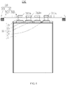
FIG. 1 is a schematic structural diagram of a battery according to an embodiment of this application. -
FIG. 2 is a schematic structural diagram of a battery according to an embodiment of this application. -
FIG. 3 is a schematic structural diagram of a battery according to an embodiment of this application. -
FIG. 4 is a schematic structural diagram of a battery according to an embodiment of this application. -
FIG. 5 is a schematic structural diagram of a battery according to an embodiment of this application. -
FIG. 6 is a schematic structural diagram of a battery according to an embodiment of this application. - This application will be further described with reference to the accompanying drawings in the following specific embodiments.
- The following clearly and completely describes the technical solutions in the embodiments of this application with reference to the accompanying drawings in the embodiments of this application. Apparently, the described embodiments are only some rather than all of the embodiments of this application. All other embodiments obtained by a person of ordinary skill in the art based on the embodiments of this application without creative efforts shall fall within the protection scope of this application.
- Unless otherwise defined, all technical and scientific terms used herein shall have the same meanings as commonly understood by those skilled in the art to which this application belongs. The terms used herein in the specification of this application are only used to describe specific embodiments, and are not intended to limit this application.
- The following describes in detail some embodiments of this application with reference to the accompanying drawings. In absence of conflicts, the following embodiments and features in the embodiments may be combined.
- Referring to
FIG. 1 , according to an embodiment of this application, abattery 100 includes acell 10 and aprotection circuit board 30. Thecell 10 is electrically connected to theprotection circuit board 30. - The
cell 10 includes acell body 11, afirst tab 13, asecond tab 15, and athird tab 17. One end of thefirst tab 13 is electrically connected to thecell body 11, and the other end of thefirst tab 13 is electrically connected to theprotection circuit board 30. Thesecond tab 15 and thefirst tab 13 have opposite polarities, and one end of thesecond tab 15 is electrically connected to thecell body 11, and the other end of thesecond tab 15 is electrically connected to theprotection circuit board 30. Thethird tab 17 and thefirst tab 13 have the same polarity, and one end of thethird tab 17 is electrically connected to thecell body 11, and the other end of thethird tab 17 is electrically connected to theprotection circuit board 30. Thecell 10 outputs voltage through thefirst tab 13 and thethird tab 17 that have the same polarity, reducing concentration of heat during the output of thecell 10 and facilitating heat dissipation. In addition, thefirst tab 13 and thethird tab 17 that have the same polarity are separately electrically connected to theprotection circuit board 30, and an internal circuit of theprotection circuit board 30 can be electrically connected to thefirst tab 13 or thethird tab 17 based on needs, to reduce wire bending or wire extension caused by avoiding device interference. This facilitates wiring in theprotection circuit board 30, making the wiring in theprotection circuit board 30 smoother, and helping reduce overall impedance of theprotection circuit board 30, thereby slowing temperature rise of theprotection circuit board 30 when the battery is used. - In this implementation, the
first tab 13 and thethird tab 17 are positive tabs, and thesecond tab 15 is a negative tab. In some other embodiments, both thefirst tab 13 and thethird tab 17 may be negative tabs, and in this case, thesecond tab 15 is a positive tab. - The
first tab 13 and thethird tab 17 are electrically connected to thecell body 11 independently of each other. - In this embodiment, the
first tab 13 is spaced apart from thethird tab 17. Preferably, thesecond tab 15 is provided between thefirst tab 13 and thethird tab 17, and is spaced apart from both thefirst tab 13 and thethird tab 17. This is more convenient for subsequent wiring of theprotection circuit board 30. - In some embodiments of this application, referring to
FIG. 2 , thethird tab 17 is electrically connected to thecell body 11 through thefirst tab 13. Specifically, one end of thefirst tab 13 is electrically connected to thecell body 11, and the other end of thefirst tab 13 is electrically connected to theprotection circuit board 30. One end of thethird tab 17 is electrically connected to thefirst tab 13, and the other end of thethird tab 17 is electrically connected to theprotection circuit board 30. In some embodiments, thethird tab 17 may be connected to thefirst tab 13 through a nickel tape or a flexible circuit board. - The
protection circuit board 30 includes acircuit board body 31 and at least oneconnector 33. Theconnector 33 is provided on thecircuit board body 31. - In some embodiments, referring to
FIG. 1 andFIG. 2 , thecircuit board body 31 is a rigid-flex board and includes arigid board area 311 and aflexible board area 313 connected to therigid board area 311. Therigid board area 311 and theflexible board area 313 are integrally designed. Theconnector 33 is provided at theflexible board area 313. - The
rigid board area 311 includes afirst input end 311a, asecond input end 311b, and athird input end 311c that are spaced apart. Thefirst input end 311a is electrically connected to thefirst tab 13, thesecond input end 311b is electrically connected to thesecond tab 15, and thethird input end 311c is electrically connected to thethird tab 17. - In this embodiment, the
circuit board body 31 includes twoflexible board areas 313 and twoconnectors 33, and therigid board area 311 is located between the twoflexible board areas 313. Preferably, oneflexible board area 313 is provided adjacent to thefirst tab 13, and the otherflexible board area 313 is provided adjacent to thethird tab 17. Eachflexible board area 313 is provided with oneconnector 33. Eachconnector 33 is electrically connected to thefirst input end 311a or thethird input end 311c, and eachconnector 33 is electrically connected to thesecond input end 311b. - In some embodiments, referring to
FIG. 3 , therigid board area 311 and theflexible board area 313 are connected through welding, which is lower in cost than an integrally designed rigid-flex board. - In some embodiments, referring to
FIG. 4 , thecell 10 may further include afourth tab 19 electrically connected to thecell body 11 and theprotection circuit board 30. Thefourth tab 19 and thesecond tab 15 have the same polarity, and thefourth tab 19 and thesecond tab 15 are electrically connected to thecell body 11 independently of each other. Thecell 10 outputs voltage through thefourth tab 19 and thesecond tab 15 that have the same polarity, further reducing concentration of heat during the output of thecell 10 and facilitating heat dissipation. In addition, thefourth tab 19 and thesecond tab 15 that have the same polarity are separately electrically connected to theprotection circuit board 30, which further facilitates the wiring in theprotection circuit board 30, thereby further slowing the temperature rise of theprotection circuit board 30 when the battery is used. - As shown in
FIG. 4 , thefourth tab 19 may be provided between thefirst tab 13 and thethird tab 17, and is spaced apart from thefirst tab 13, thesecond tab 15, and thethird tab 17. Thefourth tab 19 may alternatively be provided on a side of thethird tab 17 farther away from thesecond tab 15. Preferably, thefirst tab 13 and the adjacentsecond tab 15 are electrically connected to theconnector 33 adjacent to thefirst tab 13. Thethird tab 17 and the adjacentfourth tab 19 are electrically connected to theconnector 33 adjacent to thethird tab 17, which is more convenient for the wiring in theprotection circuit board 30. - In some embodiments, referring to
FIG. 5 , thefourth tab 19 is electrically connected to thecell body 11 through thesecond tab 15. Specifically, one end of thesecond tab 15 is connected to thecell body 11, and the other end of thesecond tab 15 is connected to theprotection circuit board 30. One end of thefourth tab 19 is electrically connected to thesecond tab 15 and the other end of thefourth tab 19 is electrically connected to theprotection circuit board 30. In some embodiments, thefourth tab 19 may be connected to thesecond tab 15 through a nickel tape or a flexible circuit board. - In some embodiments, the
fourth tab 19 may have the same polarity as thefirst tab 13. That is, there may be a plurality of tabs having the same polarity as thefirst tab 13. From this, it can be learned that there may be a plurality of tabs having the same polarity as thesecond tab 15. - In this embodiment, referring to
FIG. 6 , therigid board area 311 is folded toward thecell body 11, and theflexible board area 313 is folded toward therigid board area 311, to reduce an overall volume of thebattery 100. - The
battery 100 is applied to an electronic apparatus (not shown) to supply power to electronic components of the electronic apparatus. The electronic apparatus may be, but is not limited to, a mobile phone, a computer, an electric toy, an electric vehicle, or the like. - In addition, a person of ordinary skill in the art can make various other corresponding changes and modifications according to the technical concept of this application, and all such changes and modifications should fall within the protection scope of this application.
| |
100 |
| |
10 |
| |
30 |
| |
11 |
| |
13 |
| |
15 |
| |
17 |
| |
31 |
| |
33 |
| |
311 |
| |
313 |
| |
311a |
| |
311b |
| |
311c |
| |
19 |
Claims (10)
- A battery, comprising a cell and a protection circuit board, wherein the cell comprises:a cell body;a first tab, electrically connected to the cell body and the protection circuit board; anda second tab, electrically connected to the cell body and the protection circuit board, wherein the second tab and the first tab have opposite polarities; andthe cell further comprises:
a third tab, electrically connected to the cell body and the protection circuit board, wherein the third tab and the first tab have the same polarity. - The battery according to claim 1, characterized in that the first tab and the third tab are electrically connected to the cell body independently of each other.
- The battery according to claim 1, characterized in that the third tab is electrically connected to the cell body through the first tab.
- The battery according to claim 1, characterized in that the protection circuit board comprises a circuit board body and at least one connector, wherein each connector is provided at the circuit board body.
- The battery according to claim 4, characterized in that the circuit board body is a rigid-flex board and comprises a rigid board area and a flexible board area connected to the rigid board area, wherein the first tab, the second tab, and the third tab are connected to the rigid board area, and the connector is provided at the flexible board area.
- The battery according to claim 1, characterized in that the cell further comprises a fourth tab electrically connected to the cell body and the protection circuit board, wherein the fourth tab and the first tab have the same polarity.
- The battery according to claim 1, characterized in that the cell further comprises a fourth tab electrically connected to the cell body and the protection circuit board, wherein the fourth tab and the second tab have the same polarity.
- The battery according to claim 7, characterized in that the fourth tab and the second tab are electrically connected to the cell body independently of each other.
- The battery according to claim 7, characterized in that the fourth tab is electrically connected to the cell body through the second tab.
- An electronic apparatus, characterized by comprising the battery according to any one of claims 1 to 9.
Applications Claiming Priority (1)
| Application Number | Priority Date | Filing Date | Title |
|---|---|---|---|
| PCT/CN2020/082123 WO2021195857A1 (en) | 2020-03-30 | 2020-03-30 | Battery and electronic device using battery |
Publications (2)
| Publication Number | Publication Date |
|---|---|
| EP3916872A1 true EP3916872A1 (en) | 2021-12-01 |
| EP3916872A4 EP3916872A4 (en) | 2022-07-27 |
Family
ID=77927063
Family Applications (1)
| Application Number | Title | Priority Date | Filing Date |
|---|---|---|---|
| EP20919358.0A Pending EP3916872A4 (en) | 2020-03-30 | 2020-03-30 | Battery and electronic device using battery |
Country Status (3)
| Country | Link |
|---|---|
| EP (1) | EP3916872A4 (en) |
| CN (1) | CN216648528U (en) |
| WO (1) | WO2021195857A1 (en) |
Families Citing this family (1)
| Publication number | Priority date | Publication date | Assignee | Title |
|---|---|---|---|---|
| AU2022374192A1 (en) * | 2022-02-09 | 2023-08-24 | Hangzhou Narada Power Technology Co., Ltd. | Charging and discharging assembley, battery core and battery module |
Family Cites Families (7)
| Publication number | Priority date | Publication date | Assignee | Title |
|---|---|---|---|---|
| KR100870356B1 (en) * | 2007-03-15 | 2008-11-25 | 삼성에스디아이 주식회사 | Secondaty battery |
| US9172066B2 (en) * | 2007-09-10 | 2015-10-27 | Samsung Sdi Co., Ltd. | Protection circuit board, battery pack including the protection circuit board and method of fabricating the protection circuit board |
| KR101023895B1 (en) * | 2009-01-13 | 2011-03-22 | 삼성에스디아이 주식회사 | Battery Pack |
| US9276250B2 (en) * | 2010-08-26 | 2016-03-01 | Samsung Sdi Co., Ltd. | Battery array and battery pack having the same |
| JP2018098154A (en) * | 2016-12-16 | 2018-06-21 | リチウム エナジー アンド パワー ゲゼルシャフト ミット ベシュレンクテル ハフッング ウント コンパニー コマンディトゲゼルシャフトLithium Energy and Power GmbH & Co. KG | Power storage element, power storage device and method of manufacturing power storage element |
| CN108987655A (en) * | 2017-05-31 | 2018-12-11 | 东莞新能源科技有限公司 | Battery |
| CN209658345U (en) * | 2019-04-18 | 2019-11-19 | 东莞新能德科技有限公司 | Battery protecting plate and battery with the battery protecting plate |
-
2020
- 2020-03-30 CN CN202090000296.6U patent/CN216648528U/en active Active
- 2020-03-30 WO PCT/CN2020/082123 patent/WO2021195857A1/en unknown
- 2020-03-30 EP EP20919358.0A patent/EP3916872A4/en active Pending
Also Published As
| Publication number | Publication date |
|---|---|
| CN216648528U (en) | 2022-05-31 |
| WO2021195857A1 (en) | 2021-10-07 |
| EP3916872A4 (en) | 2022-07-27 |
Similar Documents
| Publication | Publication Date | Title |
|---|---|---|
| WO2020259322A1 (en) | Electronic device | |
| CN105322211B (en) | Battery pack and battery operating system | |
| CN108615777B (en) | Photovoltaic module | |
| CN111082493B (en) | Terminal Equipment | |
| CN209515796U (en) | Cell module encapsulation structure and mobile terminal | |
| US20220320603A1 (en) | Battery assembly for terminal device, and terminal device having same | |
| US20240021942A1 (en) | Battery box and battery module | |
| CN201146553Y (en) | Mobile terminal with solar cell panel for charging | |
| US20230032873A1 (en) | Battery and terminal device | |
| EP3916872A1 (en) | Battery and electronic device using battery | |
| CN202930986U (en) | Three-contact type contact type charging assembly | |
| EP3916903A1 (en) | Battery cell structure and battery | |
| CN211295240U (en) | Battery and electronic device | |
| US20210296740A1 (en) | Battery and electronic device including the same | |
| CN218602633U (en) | Battery and electronic equipment | |
| CN212303839U (en) | Battery and electric device with same | |
| CN215119171U (en) | Battery core, battery module and electric equipment | |
| CN205141993U (en) | DC/DC converter | |
| CN217904061U (en) | Vehicle-mounted starting power supply | |
| TWI617114B (en) | Energy recovery system converter for digital waste batteries | |
| CN207652122U (en) | Portable charging panel | |
| CN219534758U (en) | Novel high-energy lithium ion battery pack | |
| CN206864555U (en) | A kind of assembled battery | |
| CN201528216U (en) | Power supply circuit and electronic equipment | |
| CN202930985U (en) | Contact type electric energy transmission power supply electroplate structure with electricity storage device |
Legal Events
| Date | Code | Title | Description |
|---|---|---|---|
| STAA | Information on the status of an ep patent application or granted ep patent |
Free format text: STATUS: UNKNOWN |
|
| STAA | Information on the status of an ep patent application or granted ep patent |
Free format text: STATUS: THE INTERNATIONAL PUBLICATION HAS BEEN MADE |
|
| PUAI | Public reference made under article 153(3) epc to a published international application that has entered the european phase |
Free format text: ORIGINAL CODE: 0009012 |
|
| STAA | Information on the status of an ep patent application or granted ep patent |
Free format text: STATUS: REQUEST FOR EXAMINATION WAS MADE |
|
| 17P | Request for examination filed |
Effective date: 20210823 |
|
| AK | Designated contracting states |
Kind code of ref document: A1 Designated state(s): AL AT BE BG CH CY CZ DE DK EE ES FI FR GB GR HR HU IE IS IT LI LT LU LV MC MK MT NL NO PL PT RO RS SE SI SK SM TR |
|
| A4 | Supplementary search report drawn up and despatched |
Effective date: 20220629 |
|
| RIC1 | Information provided on ipc code assigned before grant |
Ipc: H01M 50/55 20210101ALI20220623BHEP Ipc: H01M 50/54 20210101ALI20220623BHEP Ipc: H01M 50/533 20210101ALI20220623BHEP Ipc: H01M 10/6551 20140101ALI20220623BHEP Ipc: H01M 10/647 20140101ALI20220623BHEP Ipc: H01M 10/42 20060101ALI20220623BHEP Ipc: H01M 10/0525 20100101AFI20220623BHEP |
|
| DAV | Request for validation of the european patent (deleted) | ||
| DAX | Request for extension of the european patent (deleted) |