EP3916417A1 - Korrektur von magnetresonanzbildern unter verwendung mehrerer magnetresonanzbildgebungssystemkonfigurationen - Google Patents
Korrektur von magnetresonanzbildern unter verwendung mehrerer magnetresonanzbildgebungssystemkonfigurationen Download PDFInfo
- Publication number
- EP3916417A1 EP3916417A1 EP20176989.0A EP20176989A EP3916417A1 EP 3916417 A1 EP3916417 A1 EP 3916417A1 EP 20176989 A EP20176989 A EP 20176989A EP 3916417 A1 EP3916417 A1 EP 3916417A1
- Authority
- EP
- European Patent Office
- Prior art keywords
- magnetic resonance
- image data
- data
- resonance image
- space data
- Prior art date
- Legal status (The legal status is an assumption and is not a legal conclusion. Google has not performed a legal analysis and makes no representation as to the accuracy of the status listed.)
- Withdrawn
Links
Images


Classifications
-
- G—PHYSICS
- G06—COMPUTING; CALCULATING OR COUNTING
- G06T—IMAGE DATA PROCESSING OR GENERATION, IN GENERAL
- G06T11/00—2D [Two Dimensional] image generation
- G06T11/003—Reconstruction from projections, e.g. tomography
- G06T11/005—Specific pre-processing for tomographic reconstruction, e.g. calibration, source positioning, rebinning, scatter correction, retrospective gating
-
- A—HUMAN NECESSITIES
- A61—MEDICAL OR VETERINARY SCIENCE; HYGIENE
- A61B—DIAGNOSIS; SURGERY; IDENTIFICATION
- A61B5/00—Measuring for diagnostic purposes; Identification of persons
- A61B5/05—Detecting, measuring or recording for diagnosis by means of electric currents or magnetic fields; Measuring using microwaves or radio waves
- A61B5/055—Detecting, measuring or recording for diagnosis by means of electric currents or magnetic fields; Measuring using microwaves or radio waves involving electronic [EMR] or nuclear [NMR] magnetic resonance, e.g. magnetic resonance imaging
-
- G—PHYSICS
- G01—MEASURING; TESTING
- G01R—MEASURING ELECTRIC VARIABLES; MEASURING MAGNETIC VARIABLES
- G01R33/00—Arrangements or instruments for measuring magnetic variables
- G01R33/20—Arrangements or instruments for measuring magnetic variables involving magnetic resonance
- G01R33/44—Arrangements or instruments for measuring magnetic variables involving magnetic resonance using nuclear magnetic resonance [NMR]
- G01R33/48—NMR imaging systems
- G01R33/4818—MR characterised by data acquisition along a specific k-space trajectory or by the temporal order of k-space coverage, e.g. centric or segmented coverage of k-space
-
- G—PHYSICS
- G01—MEASURING; TESTING
- G01R—MEASURING ELECTRIC VARIABLES; MEASURING MAGNETIC VARIABLES
- G01R33/00—Arrangements or instruments for measuring magnetic variables
- G01R33/20—Arrangements or instruments for measuring magnetic variables involving magnetic resonance
- G01R33/44—Arrangements or instruments for measuring magnetic variables involving magnetic resonance using nuclear magnetic resonance [NMR]
- G01R33/48—NMR imaging systems
- G01R33/54—Signal processing systems, e.g. using pulse sequences ; Generation or control of pulse sequences; Operator console
- G01R33/543—Control of the operation of the MR system, e.g. setting of acquisition parameters prior to or during MR data acquisition, dynamic shimming, use of one or more scout images for scan plane prescription
-
- G—PHYSICS
- G01—MEASURING; TESTING
- G01R—MEASURING ELECTRIC VARIABLES; MEASURING MAGNETIC VARIABLES
- G01R33/00—Arrangements or instruments for measuring magnetic variables
- G01R33/20—Arrangements or instruments for measuring magnetic variables involving magnetic resonance
- G01R33/44—Arrangements or instruments for measuring magnetic variables involving magnetic resonance using nuclear magnetic resonance [NMR]
- G01R33/48—NMR imaging systems
- G01R33/54—Signal processing systems, e.g. using pulse sequences ; Generation or control of pulse sequences; Operator console
- G01R33/56—Image enhancement or correction, e.g. subtraction or averaging techniques, e.g. improvement of signal-to-noise ratio and resolution
- G01R33/5608—Data processing and visualization specially adapted for MR, e.g. for feature analysis and pattern recognition on the basis of measured MR data, segmentation of measured MR data, edge contour detection on the basis of measured MR data, for enhancing measured MR data in terms of signal-to-noise ratio by means of noise filtering or apodization, for enhancing measured MR data in terms of resolution by means for deblurring, windowing, zero filling, or generation of gray-scaled images, colour-coded images or images displaying vectors instead of pixels
-
- G—PHYSICS
- G01—MEASURING; TESTING
- G01R—MEASURING ELECTRIC VARIABLES; MEASURING MAGNETIC VARIABLES
- G01R33/00—Arrangements or instruments for measuring magnetic variables
- G01R33/20—Arrangements or instruments for measuring magnetic variables involving magnetic resonance
- G01R33/44—Arrangements or instruments for measuring magnetic variables involving magnetic resonance using nuclear magnetic resonance [NMR]
- G01R33/48—NMR imaging systems
- G01R33/54—Signal processing systems, e.g. using pulse sequences ; Generation or control of pulse sequences; Operator console
- G01R33/56—Image enhancement or correction, e.g. subtraction or averaging techniques, e.g. improvement of signal-to-noise ratio and resolution
- G01R33/561—Image enhancement or correction, e.g. subtraction or averaging techniques, e.g. improvement of signal-to-noise ratio and resolution by reduction of the scanning time, i.e. fast acquiring systems, e.g. using echo-planar pulse sequences
-
- G—PHYSICS
- G01—MEASURING; TESTING
- G01R—MEASURING ELECTRIC VARIABLES; MEASURING MAGNETIC VARIABLES
- G01R33/00—Arrangements or instruments for measuring magnetic variables
- G01R33/20—Arrangements or instruments for measuring magnetic variables involving magnetic resonance
- G01R33/44—Arrangements or instruments for measuring magnetic variables involving magnetic resonance using nuclear magnetic resonance [NMR]
- G01R33/48—NMR imaging systems
- G01R33/54—Signal processing systems, e.g. using pulse sequences ; Generation or control of pulse sequences; Operator console
- G01R33/56—Image enhancement or correction, e.g. subtraction or averaging techniques, e.g. improvement of signal-to-noise ratio and resolution
- G01R33/565—Correction of image distortions, e.g. due to magnetic field inhomogeneities
- G01R33/56509—Correction of image distortions, e.g. due to magnetic field inhomogeneities due to motion, displacement or flow, e.g. gradient moment nulling
-
- G—PHYSICS
- G06—COMPUTING; CALCULATING OR COUNTING
- G06N—COMPUTING ARRANGEMENTS BASED ON SPECIFIC COMPUTATIONAL MODELS
- G06N3/00—Computing arrangements based on biological models
- G06N3/02—Neural networks
- G06N3/04—Architecture, e.g. interconnection topology
- G06N3/045—Combinations of networks
-
- G—PHYSICS
- G06—COMPUTING; CALCULATING OR COUNTING
- G06N—COMPUTING ARRANGEMENTS BASED ON SPECIFIC COMPUTATIONAL MODELS
- G06N3/00—Computing arrangements based on biological models
- G06N3/02—Neural networks
- G06N3/08—Learning methods
-
- G—PHYSICS
- G06—COMPUTING; CALCULATING OR COUNTING
- G06N—COMPUTING ARRANGEMENTS BASED ON SPECIFIC COMPUTATIONAL MODELS
- G06N3/00—Computing arrangements based on biological models
- G06N3/02—Neural networks
- G06N3/08—Learning methods
- G06N3/084—Backpropagation, e.g. using gradient descent
-
- G—PHYSICS
- G06—COMPUTING; CALCULATING OR COUNTING
- G06T—IMAGE DATA PROCESSING OR GENERATION, IN GENERAL
- G06T11/00—2D [Two Dimensional] image generation
- G06T11/003—Reconstruction from projections, e.g. tomography
- G06T11/006—Inverse problem, transformation from projection-space into object-space, e.g. transform methods, back-projection, algebraic methods
-
- A—HUMAN NECESSITIES
- A61—MEDICAL OR VETERINARY SCIENCE; HYGIENE
- A61B—DIAGNOSIS; SURGERY; IDENTIFICATION
- A61B5/00—Measuring for diagnostic purposes; Identification of persons
- A61B5/0033—Features or image-related aspects of imaging apparatus classified in A61B5/00, e.g. for MRI, optical tomography or impedance tomography apparatus; arrangements of imaging apparatus in a room
- A61B5/004—Features or image-related aspects of imaging apparatus classified in A61B5/00, e.g. for MRI, optical tomography or impedance tomography apparatus; arrangements of imaging apparatus in a room adapted for image acquisition of a particular organ or body part
- A61B5/0042—Features or image-related aspects of imaging apparatus classified in A61B5/00, e.g. for MRI, optical tomography or impedance tomography apparatus; arrangements of imaging apparatus in a room adapted for image acquisition of a particular organ or body part for the brain
-
- G—PHYSICS
- G01—MEASURING; TESTING
- G01R—MEASURING ELECTRIC VARIABLES; MEASURING MAGNETIC VARIABLES
- G01R33/00—Arrangements or instruments for measuring magnetic variables
- G01R33/20—Arrangements or instruments for measuring magnetic variables involving magnetic resonance
- G01R33/44—Arrangements or instruments for measuring magnetic variables involving magnetic resonance using nuclear magnetic resonance [NMR]
- G01R33/48—NMR imaging systems
- G01R33/54—Signal processing systems, e.g. using pulse sequences ; Generation or control of pulse sequences; Operator console
- G01R33/56—Image enhancement or correction, e.g. subtraction or averaging techniques, e.g. improvement of signal-to-noise ratio and resolution
- G01R33/561—Image enhancement or correction, e.g. subtraction or averaging techniques, e.g. improvement of signal-to-noise ratio and resolution by reduction of the scanning time, i.e. fast acquiring systems, e.g. using echo-planar pulse sequences
- G01R33/5611—Parallel magnetic resonance imaging, e.g. sensitivity encoding [SENSE], simultaneous acquisition of spatial harmonics [SMASH], unaliasing by Fourier encoding of the overlaps using the temporal dimension [UNFOLD], k-t-broad-use linear acquisition speed-up technique [k-t-BLAST], k-t-SENSE
-
- G—PHYSICS
- G01—MEASURING; TESTING
- G01R—MEASURING ELECTRIC VARIABLES; MEASURING MAGNETIC VARIABLES
- G01R33/00—Arrangements or instruments for measuring magnetic variables
- G01R33/20—Arrangements or instruments for measuring magnetic variables involving magnetic resonance
- G01R33/44—Arrangements or instruments for measuring magnetic variables involving magnetic resonance using nuclear magnetic resonance [NMR]
- G01R33/48—NMR imaging systems
- G01R33/54—Signal processing systems, e.g. using pulse sequences ; Generation or control of pulse sequences; Operator console
- G01R33/56—Image enhancement or correction, e.g. subtraction or averaging techniques, e.g. improvement of signal-to-noise ratio and resolution
- G01R33/565—Correction of image distortions, e.g. due to magnetic field inhomogeneities
- G01R33/56554—Correction of image distortions, e.g. due to magnetic field inhomogeneities caused by acquiring plural, differently encoded echo signals after one RF excitation, e.g. correction for readout gradients of alternating polarity in EPI
-
- G—PHYSICS
- G01—MEASURING; TESTING
- G01R—MEASURING ELECTRIC VARIABLES; MEASURING MAGNETIC VARIABLES
- G01R33/00—Arrangements or instruments for measuring magnetic variables
- G01R33/20—Arrangements or instruments for measuring magnetic variables involving magnetic resonance
- G01R33/44—Arrangements or instruments for measuring magnetic variables involving magnetic resonance using nuclear magnetic resonance [NMR]
- G01R33/48—NMR imaging systems
- G01R33/54—Signal processing systems, e.g. using pulse sequences ; Generation or control of pulse sequences; Operator console
- G01R33/56—Image enhancement or correction, e.g. subtraction or averaging techniques, e.g. improvement of signal-to-noise ratio and resolution
- G01R33/567—Image enhancement or correction, e.g. subtraction or averaging techniques, e.g. improvement of signal-to-noise ratio and resolution gated by physiological signals, i.e. synchronization of acquired MR data with periodical motion of an object of interest, e.g. monitoring or triggering system for cardiac or respiratory gating
- G01R33/5676—Gating or triggering based on an MR signal, e.g. involving one or more navigator echoes for motion monitoring and correction
-
- G—PHYSICS
- G06—COMPUTING; CALCULATING OR COUNTING
- G06N—COMPUTING ARRANGEMENTS BASED ON SPECIFIC COMPUTATIONAL MODELS
- G06N5/00—Computing arrangements using knowledge-based models
- G06N5/01—Dynamic search techniques; Heuristics; Dynamic trees; Branch-and-bound
-
- G—PHYSICS
- G06—COMPUTING; CALCULATING OR COUNTING
- G06T—IMAGE DATA PROCESSING OR GENERATION, IN GENERAL
- G06T2211/00—Image generation
- G06T2211/40—Computed tomography
- G06T2211/424—Iterative
Definitions
- the invention relates to Magnetic Resonance Imaging, in particular to the reduction of artifacts in magnetic resonance images.
- a large static magnetic field is used by Magnetic Resonance Imaging (MRI) scanners to align the nuclear spins of atoms as part of the procedure for producing images within the body of a patient.
- This large static magnetic field is referred to as the B0 field or the main magnetic field.
- MRI Magnetic Resonance Imaging
- Various quantities or properties of the subject can be measured spatially using MRI.
- various electrical and tissue properties of a subject can be investigated using MRI.
- a difficulty in MRI is that it may take several minutes to acquire sufficient k-space data to reconstruct the magnetic resonance image. Motion of the subject or the reception of spurious RF signals may cause artifacts or corrupt the magnetic resonance image.
- United States patent application publication US20190377047A1 discloses the use of a deep learning to train an image-to-image neural network to generate an image with reduced artifacts for a magnetic resonance imaging system.
- the image-to-image network may be applied in real time.
- the image-to-image network may (a) use an auxiliary map as an input with the MR data from the patient, (b) use sequence metadata as a controller of the encoder of the image-to-image network, and/or (c) be trained to generate contrast invariant features in the encoder using a discriminator that receives encoder features.
- the invention provides for a medical system, a computer program, and a magnetic resonance imaging system in the independent claims. Embodiments are given in the dependent claims.
- Embodiments may provide for a means of reducing artifacts or image corruption and or to accelerate image acquisition.
- An image generating neural network may be trained to receive reference magnetic resonance image data that was acquired using a second configuration of a magnetic resonance imaging system and output synthetic magnetic resonance image data.
- the synthetic magnetic resonance image data is a simulation of magnetic resonance image data acquired for a first configuration of the magnetic resonance imaging system.
- the synthetic magnetic resonance image data can then be used to improve the reconstruction of a corrected magnetic resonance image from measured k-space data acquired using the first configuration of the magnetic resonance imaging system.
- the synthetic magnetic resonance image data can in one example provide prior knowledge which can be used in a regularization term during a reconstruction.
- the synthetic magnetic resonance image data can be used to calculate synthetic k-space data which can, for example, be used to modify, supplement, correct, or replace portions of the measured k-space data.
- the invention provides for a medical system that comprises a memory storing machine-executable instructions and an image generating neural network.
- the image generating neural network is configured for outputting a synthetic magnetic resonance image in response to receiving a reference magnetic resonance image data as input.
- the image generating neural network is configured to generate the synthetic magnetic resonance image as a simulation of a magnetic resonance image data acquired according to a figresonance image data is acquired according to a second configuration of the magnetic resonance imaging system.
- the image generating neural network takes a reference magnetic resonance image data that is acquired according to a second configuration and then generates a synthetic magnetic resonance image that simulates a magnetic resonance image acquired according to a first configuration of the magnetic resonance imaging system.
- the first and second configuration could for example be a difference in the type of pulse sequence used to control the magnetic resonance imaging system to generate a specific MR contrast.
- the differences between the first and second configuration could be a change in the configuration of a similar pulse sequence.
- the TE or TR values may be changed.
- the same pulse sequence could be used with a different resolution. Often times even using different magnetic resonance imaging protocols much of the data is redundant. This enables a synthetic magnetic resonance image data to be output with a fairly high degree of accuracy.
- the image generating neural network may be trained in a straight forward way.
- a magnetic resonance imaging system may for example be used to acquire a training image using the second configuration of the magnetic resonance image and then before or after acquiring a ground truth image that is acquired with the first configuration of the magnetic resonance imaging system. Doing this once provides one pair of training data. This process may be repeated with different subjects and different configurations as desired.
- This training data may then for example be used using a back propagation or deep learning algorithm to train the image generating neural network.
- the medical system further comprises a computational system that is configured for controlling the medical system.
- the computational system may take different forms in different examples.
- the computational system may be a workstation, for example those used by a radiologist.
- the computational system may be a remote computational system or a cloud computing system that provides image processing surfaces.
- the computational system may be a computational system that controls the operation and function of a magnetic resonance imaging system.
- Execution of the machine-executable instructions causes the computational system to receive measured k-space data acquired according to the first configuration of the magnetic resonance imaging system.
- the measured k-space data is descriptive of a region of interest of a subject.
- Execution of the machine-executable instructions further causes the computational system to receive the reference magnetic resonance image data.
- the reference magnetic resonance image data is descriptive of the region of interest of the subject.
- Execution of the machine-executable instructions further causes the computational system to receive the synthetic magnetic resonance image data by inputting the reference magnetic resonance image data into the image generating neural network.
- execution of the machine-executable instructions causes the computational system to reconstruct the corrected magnetic resonance image data from the measured k-space data and the synthetic magnetic resonance image.
- the synthetic magnetic resonance image matches the first configuration which was used to acquire the measured k-space data.
- the synthetic magnetic resonance image may therefore be used to aid in the reconstruction of the corrected magnetic resonance image data.
- the magnetic resonance image data as used herein encompasses data which may be used to render or construct one or more magnetic resonance images.
- the reference magnetic resonance image data may in one example be one or more magnetic resonance images and may in some other examples even be averaged magnetic resonance images.
- the reference magnetic resonance image data may be an image or mapping generated from a magnetic resonance fingerprinting protocol.
- the synthetic magnetic resonance image data may take different formats in different examples.
- the synthetic magnetic resonance image data may be data for constructing one or more magnetic resonance images, it may be a three-dimensional magnetic resonance imaging mapping or image dataset.
- the synthetic magnetic resonance image data may also be the result of a different magnetic resonance fingerprint protocol.
- the reference magnetic resonance image data is a single magnetic resonance image or image data set.
- the reference magnetic resonance image data comprises multiple magnetic resonance images. In some cases, these multiple magnetic resonance images have been acquired using multiple configurations or contrasts.
- the second configuration of the magnetic resonance imaging system is a collection or bundle of configurations having one configuration for each image or image data set that makes up the reference magnetic resonance imaging data. As a concrete example, three or four or maybe even more magnetic resonance images acquired for different contrasts are grouped together to form the reference magnetic resonance image data.
- the image generating neural network is configured for receiving the reference magnetic resonance image data according to a predetermined image format.
- a predetermined image format For example, this could be the format of the images used to train the image generating neural network.
- Execution of the machine-executable instructions further causes the computational system to convert the reference magnetic resonance image data to the predetermined image format before inputting the reference magnetic resonance image data into the image generating neural network.
- the size of the region of interest and the voxels may be modified by using standard image transformation techniques.
- Execution of the machine-executable instructions further causes the computational system to spatially match the synthetic magnetic resonance image data to the measured k-space data before reconstructing the corrected magnetic resonance image data. This could also include modifying the view in the image as well as the positioning of the image.
- These basic image transformation techniques may be used to format the synthetic magnetic resonance image data so that it matches the first configuration of the magnetic resonance imaging system.
- the image generating neural network may be configured to output the synthetic magnetic resonance image according to a predetermined output format.
- the computational system may adapt this predetermined output format so that it matches the first configuration of the magnetic resonance imaging system.
- the measured k-space data and the synthetic magnetic resonance image data are spatially matched. This may for example enable a better comparison of the k-space data.
- the image generating neural network may have an input vector which specifies the first configuration of the magnetic resonance imaging system and the second configuration of the magnetic resonance imaging system.
- the neural network could automatically adapt the reference magnetic resonance image data and the synthetic magnetic resonance image data. However, this would require a larger amount of training for the image generating neural network.
- the synthetic magnetic resonance image data provides prior knowledge during the reconstruction of the corrected magnetic resonance image data.
- Gross structures such as the location of organs or other anatomical structures may be present in the synthetic magnetic resonance image data. This for example may be useful in replacing or modifying various parts of the measured k-space data.
- the synthetic magnetic resonance image data may also for example be used as a regularization term during reconstruction to improve the quality of the corrected magnetic resonance image data.
- execution of the machine-executable instructions further causes the computational system to reconstruct synthetic k-space data from the synthetic magnetic resonance image data.
- the measured k-space data is divided into groups of k-space data.
- the corrected magnetic resonance image data is reconstructed using the synthetic k-space data to modify at least a portion of the groups of the k-space data.
- Standard techniques may be used to go from image space of the synthetic magnetic resonance image data back to k-space data.
- the first configuration of the magnetic resonance imaging system may for example be used to calculate backwards to simulate what the k-space data would be like if it were used to produce the synthetic magnetic resonance image data.
- the coil sensitivities may be used to even generate simulated images for each coil or acquisition channel, which may then be used in turn to simulate the acquired k-space data from individual coils or channels. This may be beneficial because it may enable the compensation for noise or other errors when acquiring the measured k-space data.
- execution of the machine-executable instructions further causes the computational system to use the synthetic k-space data to determine a rigid body transformation of one or more of the groups of k-space data.
- Execution of the machine-executable instructions further causes the computational system to perform a phase and amplitude correction of the one or more groups of k-space data using the rigid body transformation. This embodiment may be beneficial because it may provide for a straight forward way of reducing the effects of rigid body motion by a subject.
- execution of the machine-executable instructions further causes the computational system to use the synthetic k-space data to determine a configuration for a pre-defined motion model.
- Execution of the machine-executable instructions further causes the computational system to perform a correction of the one or more of the groups of k-space data using the pre-defined motion model.
- a motion model which may be used to describe affine and/or non-rigid transformations or movement of the subject.
- This pre-defined motion model may be used to define how the k-space data is modified as the subject moves according to this pre-defined motion model. This may be beneficial because it may enable the correction of the measured k-space data.
- the pre-defined motion model is configured to provide a transformation of the synthetic k-space data equivalent to an affine or elastic transformation in image space.
- execution of the machine-executable instructions further causes the computational system to detect at least one incomplete k-space data sampling region in the measured k-space data. For example, some of the measured k-space data may be incomplete, corrupted or missing. Execution of the machine-executable instructions further causes the computational system to fill the incomplete k-space sampling region in the measured k-space data with the synthetic k-space data. This may be beneficial because it may improve the quality or enable the use of measured k-space data which would otherwise have to be discarded and reacquired. One situation where this may be beneficial is where the motion of the subject is monitored using a navigator or an external motion measurement system such as a camera or respiration belt. This may enable the automatic detection of k-space data that is corrupted. Once the corrupted k-space data is discarded then the incomplete k-space sampling regions can be filled with the synthetic k-space data.
- execution of the machine-executable instructions further causes the computational system to receive a motion signal descriptive of motion of the subject.
- Execution of the machine-executable instructions further causes the computational system to reconstruct the corrected magnetic resonance image data using the groups of k-space data which have a motion signal within a predetermined range.
- a motion signal which is provided. This for example could be provided from a magnetic resonance navigator or a system which measures the position of the subject or the change of the motion. For example, respirator belts and cameras may be used. The motion signal is essentially then used to gate which of the k-space data is used.
- execution of the machine-executable instructions further causes the computational system to calculate the motion signal as a synthetic motion signal by comparing the synthetic k-space data to each of the groups of k-space data. For example, each of the groups of k-space data may be compared directly to the synthetic k-space data and a fitting may be performed. This may equate to a phase and/or amplitude change of sample points. This may enable the calculation of a motion signal which may be equivalent to a navigator. This may enable the gating of which of the k-space data is used for a particular motion signal. This for example may be useful in producing cardiac phase or breathing phase magnetic resonance images.
- the synthetic motion signal may for example be calculated either in k-space or in image space depending upon how large the groups of k-space data are.
- the memory further contains an image quality evaluation module configured for outputting an image quality metric.
- Execution of the machine-executable instructions further causes the computational system to generate multiple k-space datasets by systematically replacing combinations of the groups of k-space data with portions of the synthetic k-space data.
- Execution of the machine-executable instructions further causes the computational system to generate multiple trial magnetic resonance image data by reconstructing each of the multiple k-space datasets.
- Execution of the machine-executable instructions further causes the computational system to select the corrected magnetic resonance image data from the multiple trial magnetic resonance image data by optimizing the image quality metric output of the image quality evaluation module.
- this algorithm may for example be decided how many portions of the synthetic k-space data may be used to replace groups of the k-space data.
- the iterative algorithm can go through and then systematically replace all or many combinations for the optimization process.
- This embodiment may be beneficial because it may for example enable the correction of data corrupted by noise, spurious signals, or complex involuntary motion when there would be no other way of correcting it.
- the image quality metric is determined by using a registration between the synthetic magnetic resonance image data and one of the multiple trial magnetic resonance image data.
- the synthetic magnetic resonance image data should be similar or very close to the format of what the desired corrected magnetic resonance image data should be.
- Standard registration techniques may be used to calculate a registration or mapping between the two sets of image data.
- This metric may then be used to provide the image quality metric. For example, it may measure a similarity between the position of various anatomical landmarks.
- the image quality metric is determined using the output from a trained neural network that outputs the image quality metric in response to inputting one of the multiple trial magnetic resonance images.
- the trained neural network may be trained by taking complete sets of magnetic resonance imaging data and then corrupting or causing fake motion artifacts within this data. This may then be used to assign a classification or metric which can be used for the optimization process.
- the image quality metric is determined by calculating a total image gradient of each of the multiple trial magnetic resonance images.
- the image quality metric is determined by calculating an image entropy of each of the multiple trial magnetic resonance images.
- execution of the machine-executable instructions further causes the computational system to reconstruct multiple corrected magnetic resonance image data.
- Execution of the machine-executable instructions further causes the computational system to perform any one of the following: to provide the corrected magnetic resonance image data as an average of the multiple corrected magnetic resonance image data and provide the corrected magnetic resonance image as a selection of the multiple corrected magnetic resonance images.
- one or more of the above-mentioned methods may be used to produce the corrected magnetic resonance image data. To provide a better estimate these images may all be averaged.
- the reconstruction of the corrected magnetic resonance image data from the measured k-space data and the synthetic magnetic resonance image is formulated as an optimization problem that assigns weighting factors to each of the groups of k-space data.
- Execution of the machine-executable instructions further causes the computational system to identify at least one corrupted group of k-space data selected from the groups of k-space data. This identification may be performed in different ways. In some instances, an external navigator or other signal may be used to identify the corrupted k-space data. In other examples the corrupted k-space data may be identified by comparing it to the synthetic k-space data.
- Execution of the machine-executable instructions further causes the computational system to correct the at least one corrupted group of k-space data using the synthetic k-space data.
- Execution of the machine-executable instructions further causes the computational system to assign the weighting factors for each of the groups of k-space data.
- the at least one corrupted group of k-space data is assigned a reduced value weighting factor. This may be beneficial because then in the reconstruction the measured k-space data which is remaining is given a higher weighting for the reconstruction of the corrected magnetic resonance image. Assigning the reduced value weighting factor to the corrupted group of k-space data which has been corrected enables it to participate in the reconstruction of the corrected magnetic resonance image but it has less of an effect.
- the at least one corrupted group of k-space data is selected from the group of k-space data is detected by using any one of the following: an external navigator signal, detecting missing k-space data, or by a comparison with the synthetic k-space data, and combinations thereof.
- the correction of the at least one corrupted group of k-space data using the synthetic k-space data is performed using any one of the following: by replacing the at least one corrupted group of k-space data with the synthetic k-space data, modifying or shifting the at least one corrupted group of k-space data, appending the synthetic k-space data to the at least one corrupted group of k-space data, and combinations thereof.
- the above embodiments describe a soft gating process.
- This may be a data consistency term containing weighting factors that reflecting how much of each measurement is trusted.
- the weights can be for example any positive number.
- a gating process uses weights that are either 0 or 1, which is one possibility.
- the corrected magnetic resonance image data is reconstructed according to a compressed sensing image reconstruction algorithm.
- This embodiment may be beneficial because the use of the synthetic magnetic resonance image may reduce the amount of data needed to be sampled to reconstruct the corrected magnetic resonance image data.
- the compressed sensing image reconstruction algorithm is an iterative algorithm that generates an intermediate magnetic resonance image repeatedly.
- the compressed sensing image reconstruction algorithm comprises denoising the intermediate magnetic resonance image using the synthetic magnetic resonance image data.
- the compressed sensing image reconstruction algorithm is configured to generate the intermediate magnetic resonance image by solving an optimization problem.
- the optimization problem includes a regularization term.
- the regularization term is a function of the synthetic magnetic resonance image data and performs the denoising of the intermediate magnetic resonance image using the synthetic magnetic resonance image data.
- the memory further contains an image denoising neural network configured to output a denoised magnetic resonance image data in response to receiving the intermediate magnetic resonance image data and the synthetic magnetic resonance image data as input.
- Execution of the machine-executable instructions further causes the processor to receive the filtered magnetic resonance image data by inputting the intermediate magnetic resonance image data and the synthetic magnetic resonance image data into the image denoising neural network.
- the denoised magnetic resonance image data is used as input into the iterative algorithm to generate the intermediate magnetic resonance image data repeatedly.
- the denoising neural network is configured as a filtering network. The filter is dependent upon the values of the synthetic magnetic resonance image data.
- the imaging generating neural network is further configured to receive a configuration vector as input.
- the configuration vector specifies the first configuration of the magnetic resonance imaging system and the second configuration of the magnetic resonance imaging system.
- the input generating neural network is configured by the configuration vector to control its input and output format. The use of the configuration vectors may allow to train a single network that works for a variety of pairs of configurations but it may require a larger amount of training.
- the medical system further comprises at least one magnetic resonance imaging system.
- the first configuration could be for a first magnetic resonance imaging system and the second configuration could be for a second magnetic resonance imaging system.
- the memory further contains first pulse sequence commands configured to control the at least one magnetic resonance imaging system to acquire the measured k-space data.
- the memory further contains second pulse sequence commands configured to control the at least one magnetic resonance imaging system to acquire the reference k-space data. Execution of the machine-executable instructions further causes the computational system to acquire the reference k-space data by controlling the magnetic resonance imaging system with the second pulse sequence commands. Execution of the machine-executable instructions further causes the computational system to reconstruct the reference magnetic resonance image from the reference k-space data. Execution of the machine-executable instructions further causes the computational system to acquire the measured k-space data by controlling the magnetic resonance imaging system with the first pulse sequence commands.
- execution of the machine-executable instructions further causes the computational system to construct synthetic k-space data using the synthetic magnetic resonance image.
- Execution of the machine-executable instructions further causes the computational system to control acquisition of the measured k-space data using the synthetic k-space data. For example, as the measured k-space data is acquired in groups or shots this acquired measured k-space data can be directly compared to the synthetic k-space data and this may be used to control or modify the acquisition of further measured k-space data.
- execution of the machine-executable instructions causes the computational system to control the acquisition of the measured k-space data by choosing a k-space data sampling pattern for the first pulse sequence commands using the synthetic k-space data.
- the signal in k-space has an inhomogeneous power density.
- the algorithm could look at the synthetic k-space data and see where the power density is the highest and then modify the k-space data sampling pattern to sample accordingly.
- the first pulse sequence commands are configured to control the magnetic resonance imaging system to acquire the measured k-space data in groups of k-space data.
- Execution of the machine-executable instructions further causes the computational system to calculate a comparison metric between the synthetic k-space data and each of the groups of k-space data.
- Execution of the machine-executable instructions further causes the computational system to perform a predetermined action if the comparison metric is outside of a predetermined range value.
- the comparison metric could calculate a similarity or perform a pattern matching operation between the synthetic k-space data and an acquired group of k-space data. If it matches below a predetermined amount then the predetermined action is triggered.
- the predetermined action is any one of the following: a re-acquisition of at least a portion of the groups of k-space data, a halting of the acquisition of the measured k-space data and combinations thereof.
- the corrected magnetic resonance image is reconstructed according to a parallel imaging magnetic resonance imaging reconstruction algorithm. This for example may also be combined with compressed sensing.
- the invention provides for a method of operating a medical system.
- the method comprises receiving measured k-space data acquired according to a first configuration of a magnetic resonance imaging system.
- the measured k-space data is descriptive of a region of interest of a subject.
- the method further comprises receiving reference magnetic resonance image data.
- the reference magnetic resonance image data is descriptive of a region of interest of the subject.
- the reference magnetic resonance image data is acquired according to a second configuration of the magnetic resonance imaging system.
- the method further comprises receiving synthetic magnetic resonance image data by inputting the reference magnetic resonance image into an image generating neural network.
- the image generating neural network is configured for outputting the synthetic magnetic resonance image data in response to receiving the reference magnetic resonance image data as input.
- the image generating neural network is configured to generate the synthetic magnetic resonance image data as a simulation of magnetic resonance image data acquired according to the first configuration of the magnetic resonance imaging system when the reference magnetic resonance image data is acquired according to the second configuration of the magnetic resonance imaging system.
- the method further comprises reconstructing corrected magnetic resonance image data from the measured k-space data and the synthetic magnetic resonance image data.
- the invention provides for a computer program that comprises machine-executable instructions for execution by a computational system controlling the medical system.
- the computer program further comprises an image generating neural network that is configured for outputting synthetic magnetic resonance image data in response to receiving reference magnetic resonance image data as input.
- the image generating neural network is configured to generate the synthetic magnetic resonance image data as a simulation of magnetic resonance image data acquired according to a first configuration of a magnetic resonance imaging system when the reference magnetic resonance image data is acquired according to a second configuration of the magnetic resonance imaging system.
- Execution of the machine-executable instructions causes the computational system to receive measured k-space data acquired according to the first configuration of the magnetic resonance imaging system.
- the measured k-space data is descriptive of a region of interest of a subject.
- the reference magnetic resonance image data is acquired according to the second configuration of the magnetic resonance imaging system.
- the reference magnetic resonance imaging system is descriptive of the region of interest of the subject.
- Execution of the machine-executable instructions further causes the computational system to receive the synthetic magnetic resonance image data by inputting the reference magnetic resonance image into the image generating neural network.
- Execution of the machine-executable instructions further causes the computational system to reconstruct the corrected magnetic resonance image data from the measured k-space data and the synthetic magnetic resonance image data.
- the invention provides for a magnetic resonance imaging system.
- the magnetic resonance imaging system comprises a memory storing machine-executable instructions and an image generating neural network.
- the image generating neural network is configured for outputting synthetic magnetic resonance image data in response to receiving a reference magnetic resonance image data as input.
- the image generating neural network is configured to generate the synthetic magnetic resonance image as a simulation of a magnetic resonance image acquired according to a first configuration of the magnetic resonance imaging system when the reference magnetic resonance image data is acquired according to a second configuration of the magnetic resonance imaging system.
- the memory further contains the first pulse sequence commands configured to control the magnetic resonance imaging system to acquire the measured k-space data.
- the memory further contains the second pulse sequence commands configured to control the magnetic resonance imaging system to acquire the reference k-space data.
- the magnetic resonance imaging system further comprises a computational system configured for controlling the medical system.
- Execution of the machine-executable instructions causes the computational system to acquire the reference k-space data by controlling the magnetic resonance imaging system with the second pulse sequence commands. Execution of the machine-executable instructions further causes the computational system to reconstruct the reference magnetic resonance image data from the reference k-space data. Execution of the machine-executable instructions further causes the computational system to construct synthetic k-space data using the synthetic magnetic resonance image data. Execution of the machine-executable instructions further causes the computational system to control acquisition of the measured k-space data using the first pulse sequence commands and the synthetic k-space data. For example, the synthetic k-space data can be compared to groups or shots of the measured k-space data as it is measured and used to adapt the acquisition of further measured k-space data in real time.
- execution of the machine-executable instructions causes the computational system to control the acquisition of the measured k-space data by choosing a k-space data sampling pattern for the first pulse sequence commands using the synthetic k-space data.
- the synthetic k-space data can be used to choose the k-space data sampling pattern and used to modify the first pulse sequence commands before they are executed.
- the first pulse sequence commands are configured to control the magnetic resonance imaging system to acquire the measured k-space data in groups of k-space data. Execution of the machine-executable instructions further causes the computational system to calculate a comparison metric between the synthetic k-space data and each of the groups of k-space data. Execution of the machine-executable instructions further causes the computational system to perform a predetermined action if the comparison metric is outside of a predetermined value range.
- the predetermined action is any one of the following: a re-acquisition of at least a portion of the groups of k-space data, a halting of the acquisition of the measured k-space data, and combinations thereof.
- aspects of the present invention may be embodied as an apparatus, method or computer program product. Accordingly, aspects of the present invention may take the form of an entirely hardware embodiment, an entirely software embodiment (including firmware, resident software, microcode, etc.) or an embodiment combining software and hardware aspects that may all generally be referred to herein as a "circuit,” “module” or “system.” Furthermore, aspects of the present invention may take the form of a computer program product embodied in one or more computer readable medium(s) having computer executable code embodied thereon.
- the computer readable medium may be a computer readable signal medium or a computer readable storage medium.
- a 'computer-readable storage medium' as used herein encompasses any tangible storage medium which may store instructions which are executable by a processor or computational system of a computing device.
- the computer-readable storage medium may be referred to as a computer-readable non-transitory storage medium.
- the computer-readable storage medium may also be referred to as a tangible computer readable medium.
- a computer-readable storage medium may also be able to store data which is able to be accessed by the computational system of the computing device.
- Examples of computer-readable storage media include, but are not limited to: a floppy disk, a magnetic hard disk drive, a solid state hard disk, flash memory, a USB thumb drive, Random Access Memory (RAM), Read Only Memory (ROM), an optical disk, a magneto-optical disk, and the register file of the computational system.
- Examples of optical disks include Compact Disks (CD) and Digital Versatile Disks (DVD), for example CD-ROM, CD-RW, CD-R, DVD-ROM, DVD-RW, or DVD-R disks.
- the term computer readable-storage medium also refers to various types of recording media capable of being accessed by the computer device via a network or communication link.
- data may be retrieved over a modem, over the internet, or over a local area network.
- Computer executable code embodied on a computer readable medium may be transmitted using any appropriate medium, including but not limited to wireless, wire line, optical fiber cable, RF, etc., or any suitable combination of the foregoing.
- a computer readable signal medium may include a propagated data signal with computer executable code embodied therein, for example, in baseband or as part of a carrier wave. Such a propagated signal may take any of a variety of forms, including, but not limited to, electro-magnetic, optical, or any suitable combination thereof.
- a computer readable signal medium may be any computer readable medium that is not a computer readable storage medium and that can communicate, propagate, or transport a program for use by or in connection with an instruction execution system, apparatus, or device.
- 'Computer memory' or 'memory' is an example of a computer-readable storage medium.
- Computer memory is any memory which is directly accessible to a computational system.
- 'Computer storage' or 'storage' is a further example of a computer-readable storage medium.
- Computer storage is any non-volatile computer-readable storage medium. In some embodiments computer storage may also be computer memory or vice versa.
- a 'computational system' as used herein encompasses an electronic component which is able to execute a program or machine executable instruction or computer executable code.
- References to the computational system comprising the example of "a computational system” should be interpreted as possibly containing more than one computational system or processing core.
- the computational system may for instance be a multi-core processor.
- a computational system may also refer to a collection of computational systems within a single computer system or distributed amongst multiple computer systems.
- the term computational system should also be interpreted to possibly refer to a collection or network of computing devices each comprising a processor or computational systems.
- the machine executable code or instructions may be executed by multiple computational systems or processors that may be within the same computing device or which may even be distributed across multiple computing devices.
- Machine executable instructions or computer executable code may comprise instructions or a program which causes a processor or other computational system to perform an aspect of the present invention.
- Computer executable code for carrying out operations for aspects of the present invention may be written in any combination of one or more programming languages, including an object oriented programming language such as Java, Smalltalk, C++ or the like and conventional procedural programming languages, such as the "C" programming language or similar programming languages and compiled into machine executable instructions.
- the computer executable code may be in the form of a high-level language or in a pre-compiled form and be used in conjunction with an interpreter which generates the machine executable instructions on the fly.
- the machine executable instructions or computer executable code may be in the form of programming for programmable logic gate arrays.
- the computer executable code may execute entirely on the user's computer, partly on the user's computer, as a stand-alone software package, partly on the user's computer and partly on a remote computer or entirely on the remote computer or server.
- the remote computer may be connected to the user's computer through any type of network, including a local area network (LAN) or a wide area network (WAN), or the connection may be made to an external computer (for example, through the Internet using an Internet Service Provider).
- These computer program instructions may be provided to a computational system of a general purpose computer, special purpose computer, or other programmable data processing apparatus to produce a machine, such that the instructions, which execute via the computational system of the computer or other programmable data processing apparatus, create means for implementing the functions/acts specified in the flowchart and/or block diagram block or blocks.
- machine executable instructions or computer program instructions may also be stored in a computer readable medium that can direct a computer, other programmable data processing apparatus, or other devices to function in a particular manner, such that the instructions stored in the computer readable medium produce an article of manufacture including instructions which implement the function/act specified in the flowchart and/or block diagram block or blocks.
- a 'user interface' as used herein is an interface which allows a user or operator to interact with a computer or computer system.
- a 'user interface' may also be referred to as a 'human interface device.
- a user interface may provide information or data to the operator and/or receive information or data from the operator.
- a user interface may enable input from an operator to be received by the computer and may provide output to the user from the computer.
- the user interface may allow an operator to control or manipulate a computer and the interface may allow the computer indicate the effects of the operator's control or manipulation.
- the display of data or information on a display or a graphical user interface is an example of providing information to an operator.
- the receiving of data through a keyboard, mouse, trackball, touchpad, pointing stick, graphics tablet, joystick, gamepad, webcam, headset, pedals, wired glove, remote control, and accelerometer are all examples of user interface components which enable the receiving of information or data from an operator.
- a 'hardware interface' as used herein encompasses an interface which enables the computational system of a computer system to interact with and/or control an external computing device and/or apparatus.
- a hardware interface may allow a computational system to send control signals or instructions to an external computing device and/or apparatus.
- a hardware interface may also enable a computational system to exchange data with an external computing device and/or apparatus. Examples of a hardware interface include, but are not limited to: a universal serial bus, IEEE 1394 port, parallel port, IEEE 1284 port, serial port, RS-232 port, IEEE-488 port, Bluetooth connection, Wireless local area network connection, TCP/IP connection, Ethernet connection, control voltage interface, MIDI interface, analog input interface, and digital input interface.
- a 'display' or 'display device' as used herein encompasses an output device or a user interface adapted for displaying images or data.
- a display may output visual, audio, and or tactile data.
- Examples of a display include, but are not limited to: a computer monitor, a television screen, a touch screen, tactile electronic display, Braille screen, Cathode ray tube (CRT), Storage tube, Bi-stable display, Electronic paper, Vector display, Flat panel display, Vacuum fluorescent display (VF), Light-emitting diode (LED) displays, Electroluminescent display (ELD), Plasma display panels (PDP), Liquid crystal display (LCD), Organic light-emitting diode displays (OLED), a projector, and Head-mounted display.
- VF Vacuum fluorescent display
- LED Light-emitting diode
- ELD Electroluminescent display
- PDP Plasma display panels
- LCD Liquid crystal display
- OLED Organic light-emitting diode displays
- K-space data is defined herein as being the recorded measurements of radio frequency signals emitted by atomic spins using the antenna of a Magnetic resonance apparatus during a magnetic resonance imaging scan.
- Magnetic resonance data is an example of tomographic medical image data.
- Magnetic Resonance Imaging (MRI) image, MR image, or magnetic resonance imaging data is defined herein as being the reconstructed two- or three-dimensional visualization of anatomic data contained within the magnetic resonance imaging data. This visualization can be performed using a computer.
- Fig. 1 illustrates an example of a medical system 100.
- the medical system in Fig. 1 is shown as comprising a computer which has a computational system 106.
- the computational system 106 is intended to represent one or more computational systems such as processors or cores located at one or more locations.
- the computational system 106 is shown as being connected to an optional hardware interface 104. If other components of the medical system 100 such as a magnetic resonance imaging system are present, then the hardware interface 104 could be used by the computational system 106 to communicate with it and control it.
- the medical system 100 is further shown as comprising an optional user interface 108 that may enable an operator to use and control the medical system 100.
- the medical system 100 is further shown as containing a memory 110 that is also connected to the computational system 106.
- the memory 110 is intended to represent any memory or storage that is connected to the computational system 106.
- the memory 110 is shown as containing machine-executable instructions 120.
- the machine-executable instructions 120 enable the processor 106 to perform various image processing, data processing and control functions.
- the memory 110 is further shown as containing an image generating neural network.
- the image generating neural network 122 is configured to receive a reference magnetic resonance image and then output a synthetic magnetic resonance image data 128.
- the reference magnetic resonance image data 126 is acquired or configured according to a second configuration of the magnetic resonance imaging system and the synthetic magnetic resonance image data 128 is a simulation of magnetic resonance image data acquired according to a first configuration of a magnetic resonance imaging system.
- the image generating neural network 122 may therefore enable previously acquired data to be used to either control or improve the generation of a corrected magnetic resonance image data.
- the memory 110 is further shown as containing examples of the reference magnetic resonance image data 126 and the output synthetic magnetic resonance image data 128.
- the synthetic magnetic resonance image data 128 may optionally be used to calculate synthetic k-space data 130.
- a knowledge of the first configuration of the magnetic resonance imaging system may enable the calculation of the synthetic k-space data 130 that is sampled in the same way that the measured k-space data 124 would be.
- the measured k-space data 124 acquired by a magnetic resonance imaging system acquired using the first configuration is also shown as being stored in the memory 110.
- the memory 110 is further shown as containing a corrected magnetic resonance image data 132.
- This for example may be calculated using the measured k-space data 124 and either the synthetic k-space data 130 or the synthetic magnetic resonance image data 128.
- the synthetic k-space data 130 may be used to correct or replace portions of the measured k-space data 124.
- the synthetic magnetic resonance image data 128 may be used as prior knowledge to improve the reconstruction of the corrected magnetic resonance image data 132 from the measured k-space data 124.
- the memory 110 is also shown as containing an optional image processing module 134.
- This module may for example be used for conditioning the reference magnetic resonance image data 126 such that it has a predetermined image format before it is input into the image generating neural network 122.
- the image processing module 134 may also be used to configure or modify the synthetic magnetic resonance image data 128 such that it is spatially matched to the measured k-space data 124.
- Fig. 2 shows a flowchart which illustrates a method of operating the medical system 100 of Fig. 1 .
- the measured k-space data 124 is received.
- the reference magnetic resonance image data 126 is also received.
- the synthetic magnetic resonance image data 128 is received by inputting the reference magnetic resonance image data 126 into the image generating neural network 122. It should be noted that step 200 may also be performed after step 202 or 204.
- the synthetic magnetic resonance image data 128 or the synthetic k-space data 130 is then used in step 206.
- the corrected magnetic resonance image data 132 is reconstructed using the measured k-space data 124 and the synthetic magnetic resonance image data 128 or alternatively the synthetic k-space data 130.
- Fig. 3 illustrates a further example of the medical system 300.
- the medical system illustrated in Fig. 3 is similar to the medical system 100 of Fig. 1 except that it additionally comprises a magnetic resonance imaging system 302.
- the magnetic resonance imaging system 302 comprises a magnet 304.
- the magnet 304 is a superconducting cylindrical type magnet with a bore 306 through it.
- the use of different types of magnets is also possible; for instance it is also possible to use both a split cylindrical magnet and a so called open magnet.
- a split cylindrical magnet is similar to a standard cylindrical magnet, except that the cryostat has been split into two sections to allow access to the iso-plane of the magnet, such magnets may for instance be used in conjunction with charged particle beam therapy.
- An open magnet has two magnet sections, one above the other with a space in-between that is large enough to receive a subject: the arrangement of the two sections area similar to that of a Helmholtz coil. Open magnets are popular, because the subject is less confined. Inside the cryostat of the cylindrical magnet there is a collection of superconducting coils.
- an imaging zone 308 where the magnetic field is strong and uniform enough to perform magnetic resonance imaging.
- a region of interest 309 is shown within the imaging zone 308.
- the magnetic resonance data that is acquired typically acquried for the region of interest.
- a subject 318 is shown as being supported by a subject support 320 such that at least a portion of the subject 318 is within the imaging zone 308 and the region of interest 309.
- the magnetic field gradient coils 310 are intended to be representative. Typically magnetic field gradient coils 310 contain three separate sets of coils for spatially encoding in three orthogonal spatial directions.
- a magnetic field gradient power supply supplies current to the magnetic field gradient coils. The current supplied to the magnetic field gradient coils 310 is controlled as a function of time and may be ramped or pulsed.
- a radio-frequency coil 314 Adjacent to the imaging zone 308 is a radio-frequency coil 314 for manipulating the orientations of magnetic spins within the imaging zone 308 and for receiving radio transmissions from spins also within the imaging zone 308.
- the radio frequency antenna may contain multiple coil elements.
- the radio frequency antenna may also be referred to as a channel or antenna.
- the radio-frequency coil 314 is connected to a radio frequency transceiver 316.
- the radio-frequency coil 314 and radio frequency transceiver 316 may be replaced by separate transmit and receive coils and a separate transmitter and receiver. It is understood that the radio-frequency coil 314 and the radio frequency transceiver 316 are representative.
- the radio-frequency coil 314 is intended to also represent a dedicated transmit antenna and a dedicated receive antenna.
- the transceiver 316 may also represent a separate transmitter and receivers.
- the radio-frequency coil 314 may also have multiple receive/transmit elements and the radio frequency transceiver 316 may have multiple receive/transmit channels. For example if a parallel imaging technique such as SENSE is performed, the radio-frequency could 314 will have multiple coil elements.
- the transceiver 316 and the gradient controller 312 are shown as being connected to the hardware interface 106 of a computer system 102.
- the memory 110 is further shown as containing first pulse sequence commands 330 that are configured for acquiring the measured k-space data 124 while the magnetic resonance imaging system 302 is in a first configuration.
- the second pulse sequence commands 332 are configured for acquiring reference k-space data 334 when the magnetic resonance imaging system 302 is in a second configuration.
- the memory 110 is further shown as containing the reference k-space data 334 that has been acquired when the second pulse sequence commands 332 are executed.
- the measured k-space data 124 may be acquired when the first pulse sequence commands 330 are acquired.
- the reference k-space data 334 and the measured k-space data 124 could be acquired at different times for the same subject 318 or even in different magnetic resonance imaging systems 302. In this example both are acquired during the same examination. They could for example both be acquired for the same region of interest 309 and be acquired in a spatially matched fashion.
- Fig. 4 shows a flowchart which illustrates a method of operating the medical system 300 of Fig. 3 .
- the reference k-space data 334 is acquired by controlling the magnetic resonance imaging system with the second pulse sequence commands 332.
- step 402 the reference magnetic resonance image data 126 is reconstructed from the reference k-space data 334.
- the measured k-space data 124 is acquired by controlling the magnetic resonance imaging system 302 with the first pulse sequence commands 330.
- the method proceeds and performs steps 200, 202, 204, and 206 as was illustrated in Fig. 2 .
- Fig. 5 illustrates an example of a magnetic resonance imaging system 500.
- the magnetic resonance imaging system 500 is similar to the medical system 300 of Fig. 3 except that the contents of the memory 110 are different.
- the machine-executable instructions 120 are configured such that the synthetic k-space data 130 is used to modify the acquisition of the measured k-space data 124. This for example may be useful for correcting for motion of the subject 318 as well as the failure of various channels of the radio-frequency system or noise received by the RF antenna 314.
- the memory 110 is shown as containing a corrected magnetic resonance image 502 that was constructed from the measured k-space data 124.
- the synthetic k-space data 130 may be used in several different ways to correct for the measured k-space data 124.
- the synthetic k-space data 130 could be used to choose a sampling pattern for the first pulse sequence commands 330 which would effectively choose the sample locations of the measured k-space data 124.
- the synthetic k-space data 130 could be compared to shots or groups of measured k-space data 124 as they are acquired and used to correct the acquisition or to adjust the measured k-space data 124. This could be done on the fly or after all of the measured k-space data 124 has been acquired.
- the features of Fig. 5 may be combined with the features of Figs. 1 and 3 .
- Fig. 6 shows a flowchart which illustrates a method of operating the magnetic resonance imaging system 500 of Fig. 5 .
- the reference k-space data 334 is acquired by controlling the magnetic resonance imaging system 500 with the second pulse sequence commands 332.
- the reference magnetic resonance image data 126 is reconstructed from the reference k-space data 334.
- the synthetic magnetic resonance image data 128 is received by inputting the reference magnetic resonance image data 126 into the image generating neural network 122.
- the synthetic k-space data 130 is constructed from the synthetic magnetic resonance image data 128. This for example may be constructed using an inverse Fourier transform.
- the magnetic resonance imaging system is controlled with the first pulse sequence commands 330 in order to acquire the measured k-space data 124.
- the acquisition is also controlled or adjusted using the synthetic k-space data 130.
- PI parallel imaging
- CS compressed sensing
- DL deep learning
- a "contrast” is a configuration of a magnetic resonance imaging system used to acquire k-space data.
- the main problem in MC-CS is the difficulty to model the shared information between contrasts.
- a Bayesian estimation setting is used to motivate the mathematical formulation of the problem.
- other approaches can be taken as well to justify the mathematical formulation of the MC-CS problem.
- Bayesian CS aims at providing an estimate x ⁇ of x as the minimal-mean-squared-error (MMSE) or maximum a posteriori (MAP) of the posterior distribution: p x
- p x ( x ) is the prior, ⁇ indicates proportionality up to a constant, and in the case of additive white Gaussian noise of variance ⁇ on the measurements, the posterior distribution p y
- a corresponding formulation can be made for multi-contrast compressed sensing.
- x and x' We suppose that a good reconstruction of x' is already available, and we want to use it to reconstruct x from the undersampled measurements y.
- x ⁇ argmin x 1 2 ⁇ y ⁇ Ax ⁇ 2 2 ⁇ ⁇ log p x x ⁇ ⁇ log p x
- a difficulty is that p x ( x ) and p x
- this formulation can be straightforwardly extended to more than 2 contrasts and to joint reconstruction of 2 or more contrasts.
- x and x' are not perfectly registered to each other as a result of patient motion between the scans or mismatch of the scans' resolution, field of view and planning.
- Examples may for example encode the distribution p x
- one may for example:
- the methods described in items (1) and (2), also if augmented as described in (3), can be made robust to motion and/or varying resolution and FOV between the two contrasts by the use of rigid or non-rigid motion estimation and transformations, as done for example in some CS reconstructions with an additional time dimension.
- this motion estimation can be performed once from the undersampled image A T y and the synthesized contrast N ( x' ), or at every iteration, as increasing quality of the estimate x ⁇ t allows increasing precision of the motion registration.
- An application of the above examples is the acceleration of scanning protocols that contain acquisitions of the same anatomy with several different contrasts.
- the approach described here is limited to sequential reconstruction of the contrasts (as opposed to joint, simultaneous reconstruction of several undersampled contrasts), but can easily be extended to more than two contrasts and to joint reconstruction of the contrasts.
- An entire protocol can optimally be accelerated by starting with the acquisition of a "fast" contrast with high SNR, which is then used as reference contrast in the reconstruction of subsequent contrasts that are slower to acquire, but can be accelerated more thanks to MC-CS.
- the achievable acceleration rates using MC-CS are expected to be close to the acceleration rate achieved in dynamic CS (about a factor 2 higher than classical CS).
- interscan motion can be handled as described in point (4) above.
- through-plane motion in multi-slice scans can be problematic in this aspect, therefore MC-CS would be particularly suited the sequences of 3D scans.
- Another way to reduce the motion problem would be to consider interleaved scans, which can also further reduce scan time.
- MC-CS already helps to mitigate potential motion artifacts by a shorter overall scanning time, at the same time increasing patient comfort this way.
- a contrast-to-contrast network is trained on paired or unpaired data of two well-defined contrasts A and B.
- the scanning protocol contains one sequence acquiring contrast A and one sequence acquiring contrast B, or a single sequence acquiring k-space profiles of both contrasts in an interleaved way.
- Contrast A is reconstructed first, using classical methods such as PI, CS or CS-PI, leading to a high quality image x'.
- contrast B is reconstructed from the CS-undersampled k-space measured.
- ⁇ is a wavelet transform and ⁇ a tunable regularization parameter.
- the obtained MC-CS reconstruction has far better image quality than the standard CS reconstruction.
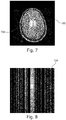
- Figs. 7-12 are used to illustrate the use of an image generating neural network 122 to assist in a compressed sensing reconstruction.
- a fully sampled image 700 is shown.
- a portion of the k-space data used to reconstruct image 700 is used.
- Fig. 8 shows an example of measured k-space data 124 that is undersampled. It is a portion of the k-spaced data used to reconstruct image 700 in Fig. 7 .
- Fig. 9 shows a wavelet compressed sensing reconstruction 900. It can be seen that the undersampled k-space data 124 in Fig. 8 was insufficient to reconstruct a quality image.
- Fig. 10 shows a different contrast or a reference magnetic resonance image data 126. Comparing images 700 and 126 it can be seen that the two images are of the same anatomy.
- Fig. 11 shows an example of a synthetic magnetic resonance image data 128 that was generated from the reference magnetic resonance image data 126 using an image generating neural network 122. The synthetic magnetic resonance image data 128 is then used with the measured k-space data 124 of Fig. 8 to reconstruct the corrected magnetic resonance image data 132 depicted in Fig. 12 . In this example the synthetic magnetic resonance image data 128 in Fig. 11 was used in the regularization term for the compressed sensing reconstruction.
- Figs. 7 to 12 are illustrations of MC-CS using a contrast-to-contrast network.
- Figs. 7 and 10 are images representing the two contrasts A and B.
- the image of Fig. 10 is available from a previous scan, while Fig. 7 represents the image to be reconstructed from the measured undersampled k-space data shown in Fig. 8.
- Fig. 7 contains an artificially brightened central region 702 to illustrate the effect of the algorithm.
- the CS reconstruction shown in Fig. 9 using sparsity in a wavelet basis, still contains strong undersampling artifacts.
- a trained contrast-to-contrast network generates an estimate 128 show in in Fig.
- contrast-to-contrast networks used in method (1) as well as the different networks used in method (2) can have varying architectures. For example, they can be fully convolutional networks such as U-net or variants of it.
- the training can be performed from a training dataset of unpaired images of contrasts A and B.
- Image degradation due to subject motion during the acquisition is a persistent problem in the clinical application of magnetic resonance imaging (MRI).
- MRI magnetic resonance imaging
- the associated artifacts typically appear as ghosting or blurring in the images and often reduce image quality to a degree that makes medical analysis impossible.
- motion artifacts only a subset of all scans in an exam suffer from motion artifacts: many patients show varying motion activities during different parts of the exam.
- some MR sequences are more sensitive with respect to motion than others.
- Fig. 13 illustrates a method of using the synthetic k-space data 130 to reduce motion artifacts in the corrected magnetic resonance image data 132.
- Block 126 represents the reference magnetic resonance image data, which in this case is a first scan that is motion free.
- Block 122 is a contrast-to-contrast conversion U-Net neural network which is equivalent to the image generating neural network 122.
- the output of this neural network 122 is the synthetic magnetic resonance image data 128, which is referred to as a converted first scan in this Fig.
- the second scan which is motion corrupted is equivalent to the measured k-space data 124.
- This is then used in an algorithm that replaces profiles in k-space 1300.
- the result is a corrected magnetic resonance image data 132. This can be performed multiple times.
- Block 1304 represents an algorithm step where the particular k-space profile that was replaced is kept if the artifact level is reduced.
- Step 1306 represents performing this iteratively for all profiles or for a certain number or a combination of k-space profiles.
- a first scan (the reference magnetic resonance image data 126) in the exam is detected as free of motion artifacts, it is converted to the target contrast (synthetic magnetic resonance image data 128) using a dedicated contrast conversion network (image generating neural network 122).
- a dedicated contrast conversion network image generating neural network 122
- a U-Net architecture was used to realize this image translation module, but other architectures are possible as well. Creation of a suitable dataset can be realized in multiple ways:
- the first motion-free scan is then converted to the target contrast, i.e. the contrast of a second scan that is corrupted by motion artifacts. If the two scans do not have the same field-of-view and resolution, the first contrast can be brought to the second contrast's geometry by adjustment of the field of view and interpolation. If necessary, an image registration algorithm may be used to account for possible patient motion between the two scans. In all cases, a synthetic k-space of the contrast-converted, registered first scan is produced using the Fourier transform and the coil sensitivity maps.
- certain k-space profiles of the second scan are then replaced by the corresponding k-space profiles of the converted first scan.
- the selection of profiles for replacement depends on the type of scan and the specific k-space acquisition scheme: for a standard consecutive cartesian scheme, only a single profile can be replaced. For the POC study, where an interleaved TSE-like acquisition was assumed, all profiles corresponding to a single TSE shot were replaced (this corresponds to the assumption of negligible motion during each shot).
- the resulting "fused" dataset is Fourier transformed to obtain the fused image in image domain.
- the artifact level in the resulting fused image is estimated using a dedicated motion artifact level estimator. Different implementations of this module are possible, e.g. classical metrics such as total image gradient, image entropy, etc.
- a dedicated regression convolutional neural network CNN was trained to estimate the L2 norm of the artifacts in the image.
- Generation of the associated training dataset was realized based on motion-free volunteer T2w images as well as an artifact simulation pipeline. If the estimated artifact level in the fused image is considerably lower than the estimated artifact level in the original image, the profile(s) are considered to be corrupted by motion.
- Figs. 14-18 illustrate the effectiveness of the method illustrated in Fig. 13 .
- Fig. 14 shows an example of a reference magnetic resonance image data 126 with a synthetic lesion 1400.
- Fig. 15 shows an example of a synthetic magnetic resonance image data 128 generated from image 126 in Fig. 14 .
- Fig. 16 shows another magnetic resonance image with motion artifacts caused by intentionally corrupting several lines of k-space data.
- Fig. 17 illustrates an example of a corrected magnetic resonance image data 132 that was reconstructed using the method illustrated in Fig. 13 with the measured k-space data 124 of Fig. 16 and the synthetic magnetic resonance image data 128 that was used to replace some of the k-space data. This image is compared to Fig.
- FIG. 18 which shows a ground truth image 1800 which contains the same k-space data used to generate image 124 in Fig. 16 except that the k-space lines were not artificially corrupted. It can be shown that the images in Figs. 17 and 18 show very good agreement.
- Fig. 19 shows the relative change of the estimated artifact level after replacement of the individual shots by the contrast-converted data shown in Fig. 15 .
- Shots #0 and #7 are correctly identified as motion-corrupted, as indicated by the large drop in estimated artifact level after replacement.
- Fig. 20 shows a flowchart which illustrates a variety of ways of reconstructing the corrected magnetic resonance image data 132.
- the steps are divided into several major steps.
- Step 2000 represents the acquisitions of the measured k-space data 124 and the reference k-space data 334.
- standard reconstructions 2002 are performed. In this step an unused or corrupted image may be reconstructed directly from the measured k-space data 124, however this is not used in this method.
- the reference magnetic resonance image data 126 is reconstructed from the reference k-space data 334.
- the image 126 is then input into the image generating neural network 122 or contrast-to-contrast network to produce the estimated image or synthetic magnetic resonance image data 128.
- the estimated image or synthetic magnetic resonance image data 128 may have its form altered by a geometry correction using a geometry modification module 134.
- the estimated image 128 may also be used to generate the estimated k-space data or synthetic k-space data 130.
- the steps in level 2006 represent several different pre-processing choices.
- k-space there may be globally corrupted k-space in which case there is a correction model which may be used. For example, in an EPI magnetic resonance image acquisition the even and odd echoes may be shifted. The estimated k-space data may be used to detect and correct this.
- Another pre-processing choice may be locally corrupted k-space data. For example, if there was an error the k-space data could be discarded and simply filled as was illustrated in Fig. 13 .
- Another pre-processing choice would be incomplete k-space. In this example you may have a choice of either proceed with an incomplete k-space or performing k-space filling. Depending upon the pre-processing choice taken in step 2006, there may also be some pre-processed k-space 2008.
- corrected k-space data may be generated as a hybrid k-space which is a combination of both the estimated k-space 130 and the actually acquired k-space 124.
- the k-space may also be so called soft gated, where replaced k-space data is given a lower weighting factor so it has less influence on the final image.
- the image may be reconstructed with an incomplete k-space or simply the profiles are discarded.
- Step 2010 represents the multi-contrast reconstruction to generate the diagnostic image 132.
- a computer program may be stored/distributed on a suitable medium, such as an optical storage medium or a solid-state medium supplied together with or as part of other hardware, but may also be distributed in other forms, such as via the Internet or other wired or wireless telecommunication systems. Any reference signs in the claims should not be construed as limiting the scope.
Landscapes
- Physics & Mathematics (AREA)
- Engineering & Computer Science (AREA)
- General Physics & Mathematics (AREA)
- Health & Medical Sciences (AREA)
- Theoretical Computer Science (AREA)
- General Health & Medical Sciences (AREA)
- High Energy & Nuclear Physics (AREA)
- Condensed Matter Physics & Semiconductors (AREA)
- Nuclear Medicine, Radiotherapy & Molecular Imaging (AREA)
- Signal Processing (AREA)
- Radiology & Medical Imaging (AREA)
- Life Sciences & Earth Sciences (AREA)
- Artificial Intelligence (AREA)
- Mathematical Physics (AREA)
- Molecular Biology (AREA)
- Biophysics (AREA)
- Biomedical Technology (AREA)
- Computing Systems (AREA)
- Software Systems (AREA)
- General Engineering & Computer Science (AREA)
- Evolutionary Computation (AREA)
- Data Mining & Analysis (AREA)
- Computational Linguistics (AREA)
- Computer Vision & Pattern Recognition (AREA)
- Mathematical Analysis (AREA)
- Algebra (AREA)
- Mathematical Optimization (AREA)
- Pure & Applied Mathematics (AREA)
- Animal Behavior & Ethology (AREA)
- Surgery (AREA)
- Pathology (AREA)
- Heart & Thoracic Surgery (AREA)
- Public Health (AREA)
- Medical Informatics (AREA)
- Veterinary Medicine (AREA)
- Magnetic Resonance Imaging Apparatus (AREA)
Priority Applications (6)
| Application Number | Priority Date | Filing Date | Title |
|---|---|---|---|
| EP20176989.0A EP3916417A1 (de) | 2020-05-28 | 2020-05-28 | Korrektur von magnetresonanzbildern unter verwendung mehrerer magnetresonanzbildgebungssystemkonfigurationen |
| CN202180034897.8A CN115552272A (zh) | 2020-05-11 | 2021-04-21 | 使用多个磁共振成像系统配置对磁共振图像的校正 |
| US17/923,617 US12067652B2 (en) | 2020-05-11 | 2021-04-21 | Correction of magnetic resonance images using multiple magnetic resonance imaging system configurations |
| PCT/EP2021/060286 WO2021228515A1 (en) | 2020-05-11 | 2021-04-21 | Correction of magnetic resonance images using multiple magnetic resonance imaging system configurations |
| EP21719164.2A EP4150360A1 (de) | 2020-05-11 | 2021-04-21 | Korrektur von magnetresonanzbildern unter verwendung mehrerer konfigurationen von magnetresonanzbildgebungssystemen |
| JP2022568522A JP2023526008A (ja) | 2020-05-11 | 2021-04-21 | 複数の磁気共鳴イメージングシステム構成を使用した磁気共鳴画像の補正 |
Applications Claiming Priority (1)
| Application Number | Priority Date | Filing Date | Title |
|---|---|---|---|
| EP20176989.0A EP3916417A1 (de) | 2020-05-28 | 2020-05-28 | Korrektur von magnetresonanzbildern unter verwendung mehrerer magnetresonanzbildgebungssystemkonfigurationen |
Publications (1)
| Publication Number | Publication Date |
|---|---|
| EP3916417A1 true EP3916417A1 (de) | 2021-12-01 |
Family
ID=70918263
Family Applications (2)
| Application Number | Title | Priority Date | Filing Date |
|---|---|---|---|
| EP20176989.0A Withdrawn EP3916417A1 (de) | 2020-05-11 | 2020-05-28 | Korrektur von magnetresonanzbildern unter verwendung mehrerer magnetresonanzbildgebungssystemkonfigurationen |
| EP21719164.2A Pending EP4150360A1 (de) | 2020-05-11 | 2021-04-21 | Korrektur von magnetresonanzbildern unter verwendung mehrerer konfigurationen von magnetresonanzbildgebungssystemen |
Family Applications After (1)
| Application Number | Title | Priority Date | Filing Date |
|---|---|---|---|
| EP21719164.2A Pending EP4150360A1 (de) | 2020-05-11 | 2021-04-21 | Korrektur von magnetresonanzbildern unter verwendung mehrerer konfigurationen von magnetresonanzbildgebungssystemen |
Country Status (5)
| Country | Link |
|---|---|
| US (1) | US12067652B2 (de) |
| EP (2) | EP3916417A1 (de) |
| JP (1) | JP2023526008A (de) |
| CN (1) | CN115552272A (de) |
| WO (1) | WO2021228515A1 (de) |
Cited By (1)
| Publication number | Priority date | Publication date | Assignee | Title |
|---|---|---|---|---|
| EP4431967A1 (de) * | 2023-03-13 | 2024-09-18 | Koninklijke Philips N.V. | Trainieren von neuronalen netzen zur erzeugung von synthetischen dreidimensionalen magnetresonanzbildern |
Families Citing this family (2)
| Publication number | Priority date | Publication date | Assignee | Title |
|---|---|---|---|---|
| EP3828579A1 (de) * | 2019-11-28 | 2021-06-02 | Koninklijke Philips N.V. | Adaptive rekonstruktion von magnetresonanzbildern |
| US11828824B2 (en) * | 2021-03-17 | 2023-11-28 | GE Precision Healthcare LLC | System and method for deep learning-based accelerated magnetic resonance imaging with extended field of view coil sensitivity calibration |
Citations (2)
| Publication number | Priority date | Publication date | Assignee | Title |
|---|---|---|---|---|
| WO2019224800A1 (en) * | 2018-05-25 | 2019-11-28 | Mahajan Vidur | Method and system for simulating and constructing original medical images from one modality to other modality |
| US20190377047A1 (en) | 2018-06-07 | 2019-12-12 | Siemens Healthcare Gmbh | Artifact Reduction by Image-to-Image Network in Magnetic Resonance Imaging |
Family Cites Families (13)
| Publication number | Priority date | Publication date | Assignee | Title |
|---|---|---|---|---|
| US8345945B2 (en) | 2006-04-21 | 2013-01-01 | The Trustees Of The University Of Pennsylvania | Motion artifact compensation |
| BRPI0916242A2 (pt) | 2008-07-16 | 2019-09-24 | The Texas A & M University System | transformação de glicerol e materiais celulósicos em combustíveis de alta energia |
| US8848990B2 (en) | 2010-09-28 | 2014-09-30 | Siemens Aktiengesellschaft | Automatic registration of image series with varying contrast based on synthetic images derived from intensity behavior model |
| US9588207B2 (en) * | 2011-10-06 | 2017-03-07 | National Institutes of Health (NIH), U.S. Dept. of Health and Human Services (DHHS), The United States of America NIH Division of Extramural Inventions and Technology Resources (DEITR) | System for reconstructing MRI images acquired in parallel |
| WO2015197366A1 (en) | 2014-06-23 | 2015-12-30 | Koninklijke Philips N.V. | Motion correction in magnetic resonance imaging |
| US9983283B2 (en) | 2015-03-16 | 2018-05-29 | Toshiba Medical Systems Corporation | Accelerated MRI using radial strips and undersampling of k-space |
| US10671939B2 (en) | 2016-04-22 | 2020-06-02 | New York University | System, method and computer-accessible medium for learning an optimized variational network for medical image reconstruction |
| US10096109B1 (en) | 2017-03-31 | 2018-10-09 | The Board Of Trustees Of The Leland Stanford Junior University | Quality of medical images using multi-contrast and deep learning |
| EP3447520A1 (de) * | 2017-08-22 | 2019-02-27 | Koninklijke Philips N.V. | Datengesteuerte phasenkorrektur in abhängigkeit von artefakten in einem magnetresonanzbildgebungssystem |
| EP3477583A1 (de) | 2017-10-31 | 2019-05-01 | Koninklijke Philips N.V. | Auf deep-learning basierte verarbeitung von bewegungsartefakten in magnetresonanz-bildgebungsdaten |
| US10573031B2 (en) | 2017-12-06 | 2020-02-25 | Siemens Healthcare Gmbh | Magnetic resonance image reconstruction with deep reinforcement learning |
| BR112020021311A2 (pt) | 2018-04-19 | 2021-01-19 | Subtle Medical, Inc. | Sistemas e métodos para aperfeiçoar a formação de imagem de ressonância magnética pela utilização de aprendizagem profunda |
| US11756160B2 (en) * | 2018-07-27 | 2023-09-12 | Washington University | ML-based methods for pseudo-CT and HR MR image estimation |
-
2020
- 2020-05-28 EP EP20176989.0A patent/EP3916417A1/de not_active Withdrawn
-
2021
- 2021-04-21 CN CN202180034897.8A patent/CN115552272A/zh active Pending
- 2021-04-21 EP EP21719164.2A patent/EP4150360A1/de active Pending
- 2021-04-21 JP JP2022568522A patent/JP2023526008A/ja active Pending
- 2021-04-21 US US17/923,617 patent/US12067652B2/en active Active
- 2021-04-21 WO PCT/EP2021/060286 patent/WO2021228515A1/en unknown
Patent Citations (2)
| Publication number | Priority date | Publication date | Assignee | Title |
|---|---|---|---|---|
| WO2019224800A1 (en) * | 2018-05-25 | 2019-11-28 | Mahajan Vidur | Method and system for simulating and constructing original medical images from one modality to other modality |
| US20190377047A1 (en) | 2018-06-07 | 2019-12-12 | Siemens Healthcare Gmbh | Artifact Reduction by Image-to-Image Network in Magnetic Resonance Imaging |
Non-Patent Citations (2)
| Title |
|---|
| LIYAN SUN ET AL: "A Deep Information Sharing Network for Multi-contrast Compressed Sensing MRI Reconstruction", ARXIV.ORG, CORNELL UNIVERSITY LIBRARY, 201 OLIN LIBRARY CORNELL UNIVERSITY ITHACA, NY 14853, 10 April 2018 (2018-04-10), XP081487176, DOI: 10.1109/TIP.2019.2925288 * |
| XIANG LEI ET AL: "Deep-Learning-Based Multi-Modal Fusion for Fast MR Reconstruction", IEEE TRANSACTIONS ON BIOMEDICAL ENGINEERING, IEEE SERVICE CENTER, PISCATAWAY, NJ, USA, vol. 66, no. 7, 1 July 2019 (2019-07-01), pages 2105 - 2114, XP011731649, ISSN: 0018-9294, [retrieved on 20190620], DOI: 10.1109/TBME.2018.2883958 * |
Cited By (1)
| Publication number | Priority date | Publication date | Assignee | Title |
|---|---|---|---|---|
| EP4431967A1 (de) * | 2023-03-13 | 2024-09-18 | Koninklijke Philips N.V. | Trainieren von neuronalen netzen zur erzeugung von synthetischen dreidimensionalen magnetresonanzbildern |
Also Published As
| Publication number | Publication date |
|---|---|
| US20230186532A1 (en) | 2023-06-15 |
| US12067652B2 (en) | 2024-08-20 |
| JP2023526008A (ja) | 2023-06-20 |
| WO2021228515A1 (en) | 2021-11-18 |
| CN115552272A (zh) | 2022-12-30 |
| EP4150360A1 (de) | 2023-03-22 |
Similar Documents
| Publication | Publication Date | Title |
|---|---|---|
| US11341616B2 (en) | Methods and system for selective removal of streak artifacts and noise from images using deep neural networks | |
| US12067652B2 (en) | Correction of magnetic resonance images using multiple magnetic resonance imaging system configurations | |
| US9709650B2 (en) | Method for calibration-free locally low-rank encouraging reconstruction of magnetic resonance images | |
| US12000918B2 (en) | Systems and methods of reconstructing magnetic resonance images using deep learning | |
| US12019135B2 (en) | Motion corrected tracer-kinetic mapping using MRI | |
| CN109477878B (zh) | 运动校正的压缩感知磁共振成像 | |
| EP3123191B1 (de) | Propeller-magnetresonanzbildgebung | |
| US11995825B2 (en) | Method for motion artifact detection | |
| US11519991B2 (en) | Motion estimation and correction in magnetic resonance imaging | |
| CN111263896B (zh) | 在磁共振成像系统中对相位相关的伪影的数据驱动的校正 | |
| EP4266074A1 (de) | Segmentierung von der aus einem satz von magnetresonanzbildern rekonstruierten medizinischen bilder | |
| CN113661404B (zh) | 使用模拟磁共振图像对磁共振图像的校正 | |
| US20230084413A1 (en) | Deep learning-based realtime reconstruction | |
| EP4163657A1 (de) | Bewegungskorrektur unter verwendung von magnetresonanzbildern mit niedriger auflösung | |
| EP3524996A1 (de) | Reduzierung von artefakten bei paralleler magnetischer resonanzbildgebung | |
| WO2024188637A1 (en) | Training of neural networks to generate synthetic three-dimensional magnetic resonance images | |
| WO2024033390A1 (en) | Two-state denoising for magnetic resonance imaging | |
| CN116266368A (zh) | 使用维数减小的神经网络进行磁共振图像处理的系统和方法 |
Legal Events
| Date | Code | Title | Description |
|---|---|---|---|
| PUAI | Public reference made under article 153(3) epc to a published international application that has entered the european phase |
Free format text: ORIGINAL CODE: 0009012 |
|
| STAA | Information on the status of an ep patent application or granted ep patent |
Free format text: STATUS: THE APPLICATION HAS BEEN PUBLISHED |
|
| AK | Designated contracting states |
Kind code of ref document: A1 Designated state(s): AL AT BE BG CH CY CZ DE DK EE ES FI FR GB GR HR HU IE IS IT LI LT LU LV MC MK MT NL NO PL PT RO RS SE SI SK SM TR |
|
| B565 | Issuance of search results under rule 164(2) epc |
Effective date: 20210202 |
|
| STAA | Information on the status of an ep patent application or granted ep patent |
Free format text: STATUS: THE APPLICATION IS DEEMED TO BE WITHDRAWN |
|
| 18D | Application deemed to be withdrawn |
Effective date: 20220602 |