EP3916369A1 - Temperature sensor and method of manufacture - Google Patents
Temperature sensor and method of manufacture Download PDFInfo
- Publication number
- EP3916369A1 EP3916369A1 EP21174803.3A EP21174803A EP3916369A1 EP 3916369 A1 EP3916369 A1 EP 3916369A1 EP 21174803 A EP21174803 A EP 21174803A EP 3916369 A1 EP3916369 A1 EP 3916369A1
- Authority
- EP
- European Patent Office
- Prior art keywords
- wire
- core
- temperature sensor
- length
- cavity
- Prior art date
- Legal status (The legal status is an assumption and is not a legal conclusion. Google has not performed a legal analysis and makes no representation as to the accuracy of the status listed.)
- Granted
Links
Images

Classifications
-
- G—PHYSICS
- G01—MEASURING; TESTING
- G01K—MEASURING TEMPERATURE; MEASURING QUANTITY OF HEAT; THERMALLY-SENSITIVE ELEMENTS NOT OTHERWISE PROVIDED FOR
- G01K7/00—Measuring temperature based on the use of electric or magnetic elements directly sensitive to heat ; Power supply therefor, e.g. using thermoelectric elements
- G01K7/02—Measuring temperature based on the use of electric or magnetic elements directly sensitive to heat ; Power supply therefor, e.g. using thermoelectric elements using thermoelectric elements, e.g. thermocouples
- G01K7/021—Particular circuit arrangements
-
- G—PHYSICS
- G01—MEASURING; TESTING
- G01K—MEASURING TEMPERATURE; MEASURING QUANTITY OF HEAT; THERMALLY-SENSITIVE ELEMENTS NOT OTHERWISE PROVIDED FOR
- G01K1/00—Details of thermometers not specially adapted for particular types of thermometer
- G01K1/08—Protective devices, e.g. casings
-
- G—PHYSICS
- G01—MEASURING; TESTING
- G01K—MEASURING TEMPERATURE; MEASURING QUANTITY OF HEAT; THERMALLY-SENSITIVE ELEMENTS NOT OTHERWISE PROVIDED FOR
- G01K7/00—Measuring temperature based on the use of electric or magnetic elements directly sensitive to heat ; Power supply therefor, e.g. using thermoelectric elements
- G01K7/16—Measuring temperature based on the use of electric or magnetic elements directly sensitive to heat ; Power supply therefor, e.g. using thermoelectric elements using resistive elements
-
- H—ELECTRICITY
- H01—ELECTRIC ELEMENTS
- H01C—RESISTORS
- H01C1/00—Details
- H01C1/02—Housing; Enclosing; Embedding; Filling the housing or enclosure
- H01C1/028—Housing; Enclosing; Embedding; Filling the housing or enclosure the resistive element being embedded in insulation with outer enclosing sheath
-
- H—ELECTRICITY
- H01—ELECTRIC ELEMENTS
- H01C—RESISTORS
- H01C3/00—Non-adjustable metal resistors made of wire or ribbon, e.g. coiled, woven or formed as grids
-
- Y—GENERAL TAGGING OF NEW TECHNOLOGICAL DEVELOPMENTS; GENERAL TAGGING OF CROSS-SECTIONAL TECHNOLOGIES SPANNING OVER SEVERAL SECTIONS OF THE IPC; TECHNICAL SUBJECTS COVERED BY FORMER USPC CROSS-REFERENCE ART COLLECTIONS [XRACs] AND DIGESTS
- Y10—TECHNICAL SUBJECTS COVERED BY FORMER USPC
- Y10T—TECHNICAL SUBJECTS COVERED BY FORMER US CLASSIFICATION
- Y10T29/00—Metal working
- Y10T29/49—Method of mechanical manufacture
- Y10T29/49002—Electrical device making
-
- Y—GENERAL TAGGING OF NEW TECHNOLOGICAL DEVELOPMENTS; GENERAL TAGGING OF CROSS-SECTIONAL TECHNOLOGIES SPANNING OVER SEVERAL SECTIONS OF THE IPC; TECHNICAL SUBJECTS COVERED BY FORMER USPC CROSS-REFERENCE ART COLLECTIONS [XRACs] AND DIGESTS
- Y10—TECHNICAL SUBJECTS COVERED BY FORMER USPC
- Y10T—TECHNICAL SUBJECTS COVERED BY FORMER US CLASSIFICATION
- Y10T29/00—Metal working
- Y10T29/49—Method of mechanical manufacture
- Y10T29/49002—Electrical device making
- Y10T29/49082—Resistor making
-
- Y—GENERAL TAGGING OF NEW TECHNOLOGICAL DEVELOPMENTS; GENERAL TAGGING OF CROSS-SECTIONAL TECHNOLOGIES SPANNING OVER SEVERAL SECTIONS OF THE IPC; TECHNICAL SUBJECTS COVERED BY FORMER USPC CROSS-REFERENCE ART COLLECTIONS [XRACs] AND DIGESTS
- Y10—TECHNICAL SUBJECTS COVERED BY FORMER USPC
- Y10T—TECHNICAL SUBJECTS COVERED BY FORMER US CLASSIFICATION
- Y10T29/00—Metal working
- Y10T29/49—Method of mechanical manufacture
- Y10T29/49002—Electrical device making
- Y10T29/49082—Resistor making
- Y10T29/49085—Thermally variable
Definitions
- the application relates generally to gas turbine engines and, more particularly to a temperature sensor which can be used in a gas turbine engine.
- RTD resistance temperature detector
- a temperature sensor comprising a core having a length extending between two ends, the core having a cavity extending along the length, a wire extending in the cavity, along the length, the wire fixed at both ends, the core having a transversal aperture at an intermediary location between the ends, the transversal aperture leading into the cavity, and a potting filling a portion of the cavity and supporting the wire at the intermediary location of the transversal aperture.
- a method of making a temperature sensor comprising : introducing potting material, in malleable form, into a gap between a wire and an inner wall of a core, via a transversal aperture in the core; solidifying the potting material for the potting material to hold a portion of the wire relative to the core thereafter, thereby impeding resonance of the wire at lower frequencies than the natural frequencies of any remaining unsupported portions of the wire.
- a gas turbine engine comprising a temperature sensor, the temperature sensor comprising a core having a length extending between two ends, the core having a cavity extending along the length, a wire extending in the cavity, along the length, the wire fixed at both ends, the core having a transversal aperture at an intermediary location between the ends, the transversal aperture leading into the cavity, and a potting filling a portion of the cavity and supporting the wire at the intermediary location of the transversal aperture.
- Fig. 1 illustrates an example of a turbine engine.
- the turbine engine 10 is a turboprop engine generally comprising in serial flow communication, a multistage compressor 12 for pressurizing the air, a combustor 14 in which the compressed air is mixed with fuel and ignited for generating an annular stream of hot combustion gases, and a turbine section 16 for extracting energy from the combustion gases.
- the turbine engine terminates in an exhaust section.
- the fluid path extending sequentially across the compressor 12, the combustor 14 and the turbine 16 can be referred to as the core gas path 18.
- the combustor 14 can include a plurality of identical, circumferentially interspaced, combustor units.
- the turboshaft engine 10 has two compressor and turbine stages, including a high pressure stage associated to a high pressure shaft 20, and a low pressure stage associated to a low pressure shaft 22.
- the low pressure shaft 22 is used as a power source during use.
- Turboprop engines similarly to turboshaft engines, typically have some form of gearing by which the power of the low pressure shaft 22 is transferred to an external shaft 26 bearing blades or propeller.
- This gearing which can be referred to as a gearbox 24 for the sake of simplicity, typically reduces the rotation speed to reach an external rotation speed which is better adapted to rotate the blades or propeller for instance.
- turboprop and turboshaft engines typically generate more vibration than turbofan engines during normal operation.
- Temperature sensors can be used at various locations on a gas turbine engine and for various reasons.
- Some temperature sensors such as some resistance temperature detectors of the wire-wound element type, for instance, have a core in which an unsupported length of a wire extends. Failure of some of such sensors has been attributed to rupture of the unsupported length of the wire due to vibrations. This was surprising because the impact of vibrations on a turbine engines are typically assessed in the design phase. High frequencies at low energy levels are typically ignored on the basis that they do not have a significant impact on the operation of the engine. It is thus counter-intuitive to think that sources of low energy, high frequency vibrations could lead to breaking of the wire, given their energy levels. However, it appeared that even at relatively low energy levels, if the frequency of the vibrations corresponded to the natural resonance frequency of the unsupported length of the wire, resonance could occur within the wire and lead to failure.
- the effective length of the wire could be changed by providing an additional support to the wire, at an intermediary location between the ends of the core, where the wire was already fixed.
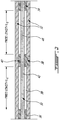
- the wire 30 can be held within the core 32 at both ends by respective pottings 34, 36.
- An additional hole, in the form of a transversal aperture 38, can provided at an intermediary location (e.g. mid-span) of the core 32, through which an additional potting 40 can be introduced into the cavity 39, around the wire 30, to support the wire 30 and prevent it from moving relative to the core 32 at that location.
- This can leave two unsupported segments 42, 44 of the wire 30, both having less than half the length of what the unsupported length would be without the additional potting. Accordingly, the natural frequency of the remaining unsupported portions 42, 44 of the wire 30 can be more than doubled due to the presence of the intermediary location potting 40.
- the wire 30 is held by pottings 34, 36 at both ends of the core 32 at both ends of the core 32 at both ends of the core 32
- extend the potting (e.g. 34) introduced at one end, along the entire length of the cavity 39 or gap.
- the wire 30 has a diameter of 0.010" (0.25mm)
- the cavity 39 has a diameter of 0.015" (0.38mm).
- a gap of roughly 0.0025" (0.64mm) is left between the wire 30 and the core 32 on all sides.
- Such a gap can be so small, depending also on the potting material, so as to prevent the potting material from penetrating beyond a certain distance.
- Such small dimensions can prevent the capillary effect from allowing the potting material in liquid phase to become absorbed along the entire length of the wire, for instance.
- Different embodiments can have different wire diameters and different internal core sizes, but it may not be feasible to introduce potting along the full length of the core, from the end, in embodiments where the diameter of the cavity is less than three times the diameter of the wire, for instance.
- Forming one or more transversal (radial) apertures 38 in the core can allow to overcome this limitation, and allow potting to reach one or more intermediary location along the wire 30.
- one or more transversal apertures 38 can be formed to introduce potting in a manner to fill the gap between the wire 30 and the core's inner wall along the entire length of the core 32, leaving no length of the wire unsupported, but this approach may be more costly and not required for many embodiments.
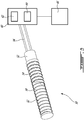
- Fig. 3 illustrates an example temperature sensor 50 of the resistance temperature detector type, having a sensing element of the wire wound type, and will be used to explain an example possible use of the technique.
- a base 52 is provided in a manner to securely receive both a core 32 and a shell 54. Both the core 32 and the shell 54 are straight hollow tubes connected to the base 52 at a proximal end.
- the core 32 is made of an electrically insulating material.
- Two electrical leads 56 penetrate into the base.
- At least one wire 30 extends in the cavity 39, along the entire length of the core 32 and connects to one of the leads 56 at the proximal end.
- a sensing coil 58 is wrapped around the core 32.
- the sensing coil 58 can be made of a very thin metal wire, such as a platinum wire having 0.001" (0.025mm) in diameter, for instance.
- the sensing coil is connected to the wire 30 at the distal end, and the wire 30 inside the core 32 thus connects the distal end of the sensing coil 58 to the first electrical lead 56.
- the proximal end of the sensing coil 58 is connected to the second one of the electrical leads 56.
- the proximal end of the sensing coil 58 can be connected to the second electrical lead 56 via a second wire which extends from the base 52, along a minor portion of the cavity 39 in the core 32. Care is taken in all electrical connections and contacts to avoid introducing noise or otherwise reducing the sensitivity of the sensor, different materials can be used to make the different segments of the electrical path, but usual care may need to be taken to avoid undesired phenomena such as corrosion.
- the shell 54 covers the sensing portion 58, which is typically very fragile given the diameter of its wire, and protects it.
- the shell is typically made of a metal having a very high thermal conductivity coefficient to allow the sensing coil 58 to be as sensitive as feasible to the temperature of its environment.
- An interrogation system 60 can be provided in connection with the leads 56, including an electrical energy source 62 configured to induce current circulation along the electrical path/circuit, including the sensing coil 58, and a meter 64 configured to measure a response of the gap to the induced current circulation.
- One form or another of computer 66 or controller can be used to associated the measured response (typically associated to a resistance value of the sensing coil 58), to a temperature, on the basis of the temperature-resistance relationship of the material of the sensing coil as stored in reference data.
- the core 32 can be a cylindrical tube of electrically insulating material such as presented in Fig. 2 .
- the wire 30 can be fixed at both ends by pottings 34, 36 introduced into the gaps present between the wire 30 and the tube at the corresponding ends.
- the pottings 34, 36 can be introduced using usual processes, which typically involve introducing a material in liquid or viscous/gelatinous form into the desired area, and solidifying that material.
- Various potting techniques and potting materials exist, and the resulting hardness can vary, but the resulting hardness is typically significantly greater after solidification.
- the core 32 has a transversal aperture 38 at mid-length, which leads from outside the core 32 into the cavity 39.
- Potting material can be introduced via the transversal aperture 38 to fill a portion of the gap between the wire 30 and the core 32, and thence be solidified so as to firmly support the wire at that intermediary location thereafter.
- the potting material cannot penetrate along the entire length of the cavity, necessitating the transversal aperture to provide the intermediary location support. Nonetheless, the presence of the intermediary potting 40 leaves two unsupported lengths of wire 42, 44, each one being between the center potting 40 and a corresponding end potting 36, 34, and the length of each one of these wire portions 42, 44 is smaller than half the length of the wire 30 between the two end pottings 34, 36. Accordingly, the natural resonance frequency of each one of these two unsupported wire portions 42, 44 is more than twice the value of the natural resonance frequency the wire 30 would have if it was not supported at the intermediary location.
- a temperature sensor such as described herein can be used in a turbofan engine instead of a turboshaft or turboprop, and may also be used in other engine types or other applications.
- the wire had a diameter of 0.010" (0.25mm). It will be understood that different diameters of wires may be used in different application and such diameters may be within a range of between 0.005" (0.13mm) and 0.020" (0.50mm), or outside the latter range.
- the core was cylindrical, and the cavity had a diameter of 0.015" (0.38mm). Cavities can have different dimensions in alternate embodiments, and can be less than 5 times the diameter of the wire, less than three times the diameter of the wire, less than two times the diameter of the wire, to name a few examples.
- the core can have a shape other than cylindrical, such as rectangular.
- the core may be curved or otherwise have a more complex shape in alternate embodiments. The way the wire is held at both ends, and electrically connected to other elements of the circuit, can vary in alternate embodiments.
Landscapes
- Physics & Mathematics (AREA)
- General Physics & Mathematics (AREA)
- Engineering & Computer Science (AREA)
- Microelectronics & Electronic Packaging (AREA)
- Measuring Temperature Or Quantity Of Heat (AREA)
Abstract
Description
- The application relates generally to gas turbine engines and, more particularly to a temperature sensor which can be used in a gas turbine engine.
- It is common to use temperature sensors for various purposes in gas turbine engines. One commonly used type of temperature sensor is the resistance temperature detector (RTD), which is based on the principle that the resistance of a metal varies depending on the temperature. In practice, RTDs typically circulate electrical current along a length of wire which is typically fine and fragile, and monitor the response of the wire to the current circulation. The amount of current circulated at a constant difference of potential, or the amount of difference of potential stemming from a fixed current, will vary in accordance with resistance based on the relationship V=RI. Platinum is an interesting material for use in the wire, because its resistance vs. temperature relationship is constant over a large range of temperature, but other metals, such as nickel and copper, have been used as well.
- While existing temperature sensors are satisfactory to a certain degree, there always remains room for improvement. In particular, there was a desire to improve the reliability and/or its useful life expectancy while controlling cost and weight, for instance.
- In one aspect, there is provided a temperature sensor comprising a core having a length extending between two ends, the core having a cavity extending along the length, a wire extending in the cavity, along the length, the wire fixed at both ends, the core having a transversal aperture at an intermediary location between the ends, the transversal aperture leading into the cavity, and a potting filling a portion of the cavity and supporting the wire at the intermediary location of the transversal aperture.
- In another aspect, there is provided a method of making a temperature sensor, the method comprising : introducing potting material, in malleable form, into a gap between a wire and an inner wall of a core, via a transversal aperture in the core; solidifying the potting material for the potting material to hold a portion of the wire relative to the core thereafter, thereby impeding resonance of the wire at lower frequencies than the natural frequencies of any remaining unsupported portions of the wire.
- In a further aspect, there is provided a gas turbine engine comprising a temperature sensor, the temperature sensor comprising a core having a length extending between two ends, the core having a cavity extending along the length, a wire extending in the cavity, along the length, the wire fixed at both ends, the core having a transversal aperture at an intermediary location between the ends, the transversal aperture leading into the cavity, and a potting filling a portion of the cavity and supporting the wire at the intermediary location of the transversal aperture.
- Reference is now made to the accompanying figures in which:
-
Fig. 1 is a schematic cross-sectional view of a gas turbine engine; -
Fig. 2 is a cross sectional view of a core of a temperature sensor, taken along a longitudinal plane. -
Fig. 3 is an oblique view of a temperature sensor incorporating the core ofFig. 2 . -
Fig. 1 illustrates an example of a turbine engine. In this example, theturbine engine 10 is a turboprop engine generally comprising in serial flow communication, amultistage compressor 12 for pressurizing the air, acombustor 14 in which the compressed air is mixed with fuel and ignited for generating an annular stream of hot combustion gases, and aturbine section 16 for extracting energy from the combustion gases. The turbine engine terminates in an exhaust section. - The fluid path extending sequentially across the
compressor 12, thecombustor 14 and theturbine 16 can be referred to as thecore gas path 18. In practice, thecombustor 14 can include a plurality of identical, circumferentially interspaced, combustor units. In the embodiment shown inFig. 1 , theturboshaft engine 10 has two compressor and turbine stages, including a high pressure stage associated to ahigh pressure shaft 20, and a low pressure stage associated to alow pressure shaft 22. Thelow pressure shaft 22 is used as a power source during use. - Turboprop engines, similarly to turboshaft engines, typically have some form of gearing by which the power of the
low pressure shaft 22 is transferred to anexternal shaft 26 bearing blades or propeller. This gearing, which can be referred to as agearbox 24 for the sake of simplicity, typically reduces the rotation speed to reach an external rotation speed which is better adapted to rotate the blades or propeller for instance. Due to the presence of blades or propeller and/or gearing, turboprop and turboshaft engines typically generate more vibration than turbofan engines during normal operation. - Temperature sensors can be used at various locations on a gas turbine engine and for various reasons. Some temperature sensors, such as some resistance temperature detectors of the wire-wound element type, for instance, have a core in which an unsupported length of a wire extends. Failure of some of such sensors has been attributed to rupture of the unsupported length of the wire due to vibrations. This was surprising because the impact of vibrations on a turbine engines are typically assessed in the design phase. High frequencies at low energy levels are typically ignored on the basis that they do not have a significant impact on the operation of the engine. It is thus counter-intuitive to think that sources of low energy, high frequency vibrations could lead to breaking of the wire, given their energy levels. However, it appeared that even at relatively low energy levels, if the frequency of the vibrations corresponded to the natural resonance frequency of the unsupported length of the wire, resonance could occur within the wire and lead to failure.
- It was theorized that failure could occur due to harmonic excitation at frequencies that were relatively high, e.g. above 2000Hz, perhaps around 2500 Hz in some embodiments, and which were typically not monitored given their relatively low energy. It appeared to plausible, given the size and strength of this wire, that even low energy vibes could excite and break the wire. A solution was proposed in the form of changing the resonant frequency of the wire to avoid the problematic frequencies.
- The natural frequency of a wire can be changed by changing its length. More specifically, the natural frequency of a fixed beam with uniform load w per unit length including beam weight is as follows:

- The effective length of the wire, and thus its frequency, could be changed by providing an additional support to the wire, at an intermediary location between the ends of the core, where the wire was already fixed.
- Referring to
Fig. 2 , in one embodiment, thewire 30 can be held within thecore 32 at both ends byrespective pottings transversal aperture 38, can provided at an intermediary location (e.g. mid-span) of thecore 32, through which anadditional potting 40 can be introduced into thecavity 39, around thewire 30, to support thewire 30 and prevent it from moving relative to thecore 32 at that location. This can leave twounsupported segments wire 30, both having less than half the length of what the unsupported length would be without the additional potting. Accordingly, the natural frequency of the remainingunsupported portions wire 30 can be more than doubled due to the presence of the intermediary location potting 40. Even further increase in the unsupported length natural resonance frequencies can be achieved by adding more pottings, at multiple intermediary locations. Increasing the frequency of the wire can allow to increase the reliability of the wire by preventing its natural frequency to coincide with potentially problematic engine vibration frequencies. It will be understood that in the final product, the intermediary potting(s) 40 will likely be exposed via the correspondingtransversal apertures 38, and may partially or entirely fill thetransversal aperture 38. - One alternative avenue to an embodiment where the
wire 30 is held bypottings core 32 would be to extend the potting (e.g. 34), introduced at one end, along the entire length of thecavity 39 or gap. However, in practice, this is not feasible in many embodiments. For instance, in one embodiment, thewire 30 has a diameter of 0.010" (0.25mm), whereas thecavity 39 has a diameter of 0.015" (0.38mm). A gap of roughly 0.0025" (0.64mm) is left between thewire 30 and thecore 32 on all sides. Such a gap can be so small, depending also on the potting material, so as to prevent the potting material from penetrating beyond a certain distance. Such small dimensions can prevent the capillary effect from allowing the potting material in liquid phase to become absorbed along the entire length of the wire, for instance. Different embodiments can have different wire diameters and different internal core sizes, but it may not be feasible to introduce potting along the full length of the core, from the end, in embodiments where the diameter of the cavity is less than three times the diameter of the wire, for instance. Forming one or more transversal (radial)apertures 38 in the core can allow to overcome this limitation, and allow potting to reach one or more intermediary location along thewire 30. In one embodiment, one or moretransversal apertures 38 can be formed to introduce potting in a manner to fill the gap between thewire 30 and the core's inner wall along the entire length of thecore 32, leaving no length of the wire unsupported, but this approach may be more costly and not required for many embodiments. -
Fig. 3 illustrates anexample temperature sensor 50 of the resistance temperature detector type, having a sensing element of the wire wound type, and will be used to explain an example possible use of the technique. In this example, abase 52 is provided in a manner to securely receive both acore 32 and ashell 54. Both thecore 32 and theshell 54 are straight hollow tubes connected to thebase 52 at a proximal end. Thecore 32 is made of an electrically insulating material. Twoelectrical leads 56 penetrate into the base. At least onewire 30 extends in thecavity 39, along the entire length of thecore 32 and connects to one of theleads 56 at the proximal end. Asensing coil 58 is wrapped around thecore 32. Thesensing coil 58 can be made of a very thin metal wire, such as a platinum wire having 0.001" (0.025mm) in diameter, for instance. The sensing coil is connected to thewire 30 at the distal end, and thewire 30 inside the core 32 thus connects the distal end of thesensing coil 58 to the firstelectrical lead 56. The proximal end of thesensing coil 58 is connected to the second one of the electrical leads 56. In some embodiments, the proximal end of thesensing coil 58 can be connected to the secondelectrical lead 56 via a second wire which extends from thebase 52, along a minor portion of thecavity 39 in thecore 32. Care is taken in all electrical connections and contacts to avoid introducing noise or otherwise reducing the sensitivity of the sensor, different materials can be used to make the different segments of the electrical path, but usual care may need to be taken to avoid undesired phenomena such as corrosion. - The
shell 54 covers thesensing portion 58, which is typically very fragile given the diameter of its wire, and protects it. The shell is typically made of a metal having a very high thermal conductivity coefficient to allow thesensing coil 58 to be as sensitive as feasible to the temperature of its environment. - An
interrogation system 60 can be provided in connection with theleads 56, including anelectrical energy source 62 configured to induce current circulation along the electrical path/circuit, including thesensing coil 58, and ameter 64 configured to measure a response of the gap to the induced current circulation. One form or another ofcomputer 66 or controller can be used to associated the measured response (typically associated to a resistance value of the sensing coil 58), to a temperature, on the basis of the temperature-resistance relationship of the material of the sensing coil as stored in reference data. - In this example, the core 32 can be a cylindrical tube of electrically insulating material such as presented in
Fig. 2 . Thewire 30 can be fixed at both ends by pottings 34, 36 introduced into the gaps present between thewire 30 and the tube at the corresponding ends. Thepottings Fig. 2 , thecore 32 has atransversal aperture 38 at mid-length, which leads from outside the core 32 into thecavity 39. Potting material can be introduced via thetransversal aperture 38 to fill a portion of the gap between thewire 30 and thecore 32, and thence be solidified so as to firmly support the wire at that intermediary location thereafter. In this example, the potting material cannot penetrate along the entire length of the cavity, necessitating the transversal aperture to provide the intermediary location support. Nonetheless, the presence of theintermediary potting 40 leaves two unsupported lengths ofwire wire portions wire 30 between the twoend pottings unsupported wire portions wire 30 would have if it was not supported at the intermediary location. - The embodiments described in this document provide non-limiting examples of possible implementations of the present technology. Upon review of the present disclosure, a person of ordinary skill in the art will recognize that changes may be made to the embodiments described herein without departing from the scope of the present technology. For example, a temperature sensor such as described herein can be used in a turbofan engine instead of a turboshaft or turboprop, and may also be used in other engine types or other applications. In a specific example presented above, the wire had a diameter of 0.010" (0.25mm). It will be understood that different diameters of wires may be used in different application and such diameters may be within a range of between 0.005" (0.13mm) and 0.020" (0.50mm), or outside the latter range. In a specific embodiment presented above, the core was cylindrical, and the cavity had a diameter of 0.015" (0.38mm). Cavities can have different dimensions in alternate embodiments, and can be less than 5 times the diameter of the wire, less than three times the diameter of the wire, less than two times the diameter of the wire, to name a few examples. In alternate embodiments, the core can have a shape other than cylindrical, such as rectangular. Moreover, rather than being straight, the core may be curved or otherwise have a more complex shape in alternate embodiments. The way the wire is held at both ends, and electrically connected to other elements of the circuit, can vary in alternate embodiments. Moreover, the techniques presented above and illustrated may be useful in reducing the natural resonance frequency of a wire held in a core in applications other than a temperature sensor. Multiple pottings can be introduced to support the wire at multiple locations between the ends of the wire. Yet further modifications could be implemented by a person of ordinary skill in the art in view of the present disclosure, which modifications would be within the scope of the present technology.
Claims (14)
- A temperature sensor (50) comprising a core (32) having a length extending between a first end and a second end, the core (32) having a cavity (39) extending along the length, a wire extending in the cavity (39), along the length, the wire fixed at the first end and at the second end, the core (32) having a transversal aperture (38) at an intermediary location between the ends, the transversal aperture (38) leading into the cavity (39), and a potting (40) filling a portion of the cavity (39) and supporting the wire at the intermediary location of the transversal aperture (38).
- The temperature sensor (50) of claim 1, further comprising at least two unsupported portions (42, 44) of the wire (30), each between the potting (40) and a corresponding end, the length of each unsupported portion (42, 44) of the wire (30) being smaller than a length of the wire (30) between the two ends.
- The temperature sensor (50) of claim 1 or 2 further comprising at least two of said transversal apertures (38) and pottings (40), the transversal apertures (38) and pottings (34, 36, 40) being interspaced along the length of the core (32) and supporting the wire at respective intermediary locations between the ends.
- The temperature sensor (50) of any of claims 1 to 3 wherein a diameter of the wire (30) is of between 0.005" (0.13mm) and 0.020" (0.50mm).
- The temperature sensor (50) of any preceding claim wherein the core (32) is cylindrical and the cavity (39) has a diameter of less than 3 times a diameter of the wire.
- The temperature sensor (50) of any preceding claim wherein the core (32) is made of an electrically insulating material.
- The temperature sensor (50) of any preceding claim wherein the wire (30) is fixed at both ends by corresponding pottings (34, 36).
- The temperature sensor (50) of any preceding claim wherein the wire (30) is made of platinum.
- The temperature sensor (50) of any preceding claim wherein a sensing coil (58) is wrapped around the core (32), the sensing coil (58) is made of a material having a diameter smaller than a diameter of the wire (30), the sensing coil (58) being electrically connected to the wire (30) at a distal one of the ends.
- The temperature sensor (50) of claim 9 further comprising a first electrical lead (56) connected to the wire (30) at a proximal one of the ends, and a second electrical lead (56) connected to the sensing coil (58) at the proximal end, a base (52) supporting the coil (58), and a metal shell (54) secured to the base (52) and covering the core (32) and the sensing coil (58), an electrical power source (62) for inducing current circulation along the sensing coil (58) via the leads (56), and a meter (64) for measuring a response of the sensing coil (58) to the induced current circulation.
- A method of making a temperature sensor (50), the method comprising :introducing material into a gap (39) between a wire (30) of the sensor (50) and an inner wall of a core (32) of the sensor, via a transversal aperture (38) in the core (32);said material holding a portion of the wire (30) relative to the core (32) thereafter.
- The method of claim 11 wherein said material is potting material (40) initially introduced in malleable form and subsequently solidified.
- The method of claim 12 further comprising introducing said potting material (34, 36), in malleable form, into the gap (39) between the wire (30) and the inner wall of the core (32), via the ends of the core (32), and solidifying the potting material (34, 36) introduced via the ends of the core (32).
- The method of claim 13 wherein the step of introducing potting material (40) via the transversal aperture (38) is performed subsequently to the step of introducing potting material (34, 36) via the ends, and the holding of the wire (30) relative to the core (32) increases the natural frequency of unsupported portions of the wire (30) compared to the natural frequency of the wire (30) prior to introducing the potting material (40) via the transversal aperture (38).
Applications Claiming Priority (1)
| Application Number | Priority Date | Filing Date | Title |
|---|---|---|---|
| US16/878,792 US11709103B2 (en) | 2020-05-20 | 2020-05-20 | Temperature sensor and method of manufacture |
Publications (2)
| Publication Number | Publication Date |
|---|---|
| EP3916369A1 true EP3916369A1 (en) | 2021-12-01 |
| EP3916369B1 EP3916369B1 (en) | 2023-03-08 |
Family
ID=76011855
Family Applications (1)
| Application Number | Title | Priority Date | Filing Date |
|---|---|---|---|
| EP21174803.3A Active EP3916369B1 (en) | 2020-05-20 | 2021-05-19 | Temperature sensor and method of manufacture |
Country Status (3)
| Country | Link |
|---|---|
| US (1) | US11709103B2 (en) |
| EP (1) | EP3916369B1 (en) |
| CA (1) | CA3119123A1 (en) |
Citations (3)
| Publication number | Priority date | Publication date | Assignee | Title |
|---|---|---|---|---|
| US20040182163A1 (en) * | 2003-03-19 | 2004-09-23 | Denso Corporation | Pressure sensor device having temperature sensor |
| DE102016111738A1 (en) * | 2016-06-27 | 2017-12-28 | Heraeus Sensor Technology Gmbh | Cable for contacting a sensor, temperature measuring device, method for connecting a cable to a temperature measuring device and use of an alloy for producing a cable |
| US10132667B2 (en) * | 2014-03-17 | 2018-11-20 | Auxitrol S.A. | Method of manufacturing an element sensitive to a physical parameter of a flow of fluid and corresponding sensitive element |
Family Cites Families (11)
| Publication number | Priority date | Publication date | Assignee | Title |
|---|---|---|---|---|
| US3761857A (en) * | 1971-10-04 | 1973-09-25 | Rosemount Inc | Resistance wire temperature sensor and method of making same |
| DE2411995A1 (en) * | 1973-04-20 | 1974-10-31 | Plansee Metallwerk | DEVICE FOR TEMPERATURE MEASUREMENT USING THERMOCOUPLES |
| US3798760A (en) * | 1973-05-11 | 1974-03-26 | Rosemount Inc | Method of making resistance wire temperature sensor |
| GB1454816A (en) * | 1974-02-19 | 1976-11-03 | Rosemount Eng Co Ltd | Resistance thermometer sensors |
| US4934831A (en) * | 1989-03-20 | 1990-06-19 | Claud S. Gordon Company | Temperature sensing device |
| US5119036A (en) | 1990-05-29 | 1992-06-02 | General Electric Company | Electrical capacitance clearanceometer |
| US7004626B1 (en) * | 2004-03-05 | 2006-02-28 | Turbo Research, Inc. | Fast acting thermocouple |
| DE102009028850A1 (en) * | 2009-08-24 | 2011-03-03 | Endress + Hauser Flowtec Ag | Manufacturing method of a sensor of a thermal flow meter |
| US9103731B2 (en) * | 2012-08-20 | 2015-08-11 | Unison Industries, Llc | High temperature resistive temperature detector for exhaust gas temperature measurement |
| GB2522210B (en) | 2014-01-16 | 2018-10-10 | Weston Aerospace Ltd | Engine probe |
| US20170343423A1 (en) * | 2016-05-26 | 2017-11-30 | Vertiv Energy Systems, Inc. | Temperature sensor assemblies and methods for coupling a thermistor to a cable |
-
2020
- 2020-05-20 US US16/878,792 patent/US11709103B2/en active Active
-
2021
- 2021-05-18 CA CA3119123A patent/CA3119123A1/en active Pending
- 2021-05-19 EP EP21174803.3A patent/EP3916369B1/en active Active
Patent Citations (3)
| Publication number | Priority date | Publication date | Assignee | Title |
|---|---|---|---|---|
| US20040182163A1 (en) * | 2003-03-19 | 2004-09-23 | Denso Corporation | Pressure sensor device having temperature sensor |
| US10132667B2 (en) * | 2014-03-17 | 2018-11-20 | Auxitrol S.A. | Method of manufacturing an element sensitive to a physical parameter of a flow of fluid and corresponding sensitive element |
| DE102016111738A1 (en) * | 2016-06-27 | 2017-12-28 | Heraeus Sensor Technology Gmbh | Cable for contacting a sensor, temperature measuring device, method for connecting a cable to a temperature measuring device and use of an alloy for producing a cable |
Also Published As
| Publication number | Publication date |
|---|---|
| EP3916369B1 (en) | 2023-03-08 |
| CA3119123A1 (en) | 2021-11-20 |
| US20210364366A1 (en) | 2021-11-25 |
| US11709103B2 (en) | 2023-07-25 |
Similar Documents
| Publication | Publication Date | Title |
|---|---|---|
| US11441444B2 (en) | Electrical resistance wear indicator | |
| CN102762968B (en) | Fatigue resistant thermowell and methods | |
| EP2410301B1 (en) | Systems and methods for liquid level sensing having a differentiating output | |
| JP4943282B2 (en) | Device for resonant frequency response damping | |
| US10436732B2 (en) | Near full hoop electrical axial shift wear indication sensor | |
| CN101576420B (en) | Temperature sensor | |
| US10996082B2 (en) | Sensor system for a rotor assembly | |
| US20030122682A1 (en) | Crack detection in fracture-critical machine parts | |
| EP3361229A2 (en) | System and method for blade health monitoring | |
| US2575710A (en) | Apparatus for measuring rotor blade vibration | |
| US20170260871A1 (en) | Engine Health Monitoring Using Acoustic Sensors | |
| EP2816200A1 (en) | Method and device for suppressing the formation of ice on structures at the air intake of a turbomachine | |
| JP6461459B2 (en) | High temperature resistance thermometer for measuring exhaust gas temperature | |
| JP2007051634A (en) | Clearance control method for turbo machine, control device and turbine engine apparatus | |
| US20160195411A1 (en) | Encapsulated Soft-Lead Capacitance Probe for a Gas Turbine Engine | |
| US20160108756A1 (en) | Turbo machine and method for operating such turbo machine | |
| JP6431665B2 (en) | Capacitive sensor device and method of manufacture | |
| US20180258786A1 (en) | Sensor assembly for rotating devices and methods for fabricating | |
| EP3916369B1 (en) | Temperature sensor and method of manufacture | |
| US20130323023A1 (en) | Dynamic Fiber Temperature Sensing Package And Method Of Assembling The Same | |
| US12091987B2 (en) | Steam turbine blade, steam turbine, and method for operating same | |
| KR200450290Y1 (en) | Engine exhaust gas temperature sensing element | |
| US11041404B2 (en) | In-situ wireless monitoring of engine bearings | |
| JPS60166815A (en) | Gas turbine compressor blade deposit monitoring device | |
| KR100436559B1 (en) | Self-diagnosis thermometer and temperature Repayment system using it |
Legal Events
| Date | Code | Title | Description |
|---|---|---|---|
| PUAI | Public reference made under article 153(3) epc to a published international application that has entered the european phase |
Free format text: ORIGINAL CODE: 0009012 |
|
| STAA | Information on the status of an ep patent application or granted ep patent |
Free format text: STATUS: THE APPLICATION HAS BEEN PUBLISHED |
|
| AK | Designated contracting states |
Kind code of ref document: A1 Designated state(s): AL AT BE BG CH CY CZ DE DK EE ES FI FR GB GR HR HU IE IS IT LI LT LU LV MC MK MT NL NO PL PT RO RS SE SI SK SM TR |
|
| B565 | Issuance of search results under rule 164(2) epc |
Effective date: 20211029 |
|
| STAA | Information on the status of an ep patent application or granted ep patent |
Free format text: STATUS: REQUEST FOR EXAMINATION WAS MADE |
|
| 17P | Request for examination filed |
Effective date: 20220318 |
|
| RBV | Designated contracting states (corrected) |
Designated state(s): AL AT BE BG CH CY CZ DE DK EE ES FI FR GB GR HR HU IE IS IT LI LT LU LV MC MK MT NL NO PL PT RO RS SE SI SK SM TR |
|
| GRAP | Despatch of communication of intention to grant a patent |
Free format text: ORIGINAL CODE: EPIDOSNIGR1 |
|
| STAA | Information on the status of an ep patent application or granted ep patent |
Free format text: STATUS: GRANT OF PATENT IS INTENDED |
|
| INTG | Intention to grant announced |
Effective date: 20220914 |
|
| GRAS | Grant fee paid |
Free format text: ORIGINAL CODE: EPIDOSNIGR3 |
|
| GRAA | (expected) grant |
Free format text: ORIGINAL CODE: 0009210 |
|
| STAA | Information on the status of an ep patent application or granted ep patent |
Free format text: STATUS: THE PATENT HAS BEEN GRANTED |
|
| AK | Designated contracting states |
Kind code of ref document: B1 Designated state(s): AL AT BE BG CH CY CZ DE DK EE ES FI FR GB GR HR HU IE IS IT LI LT LU LV MC MK MT NL NO PL PT RO RS SE SI SK SM TR |
|
| REG | Reference to a national code |
Ref country code: CH Ref legal event code: EP Ref country code: AT Ref legal event code: REF Ref document number: 1552872 Country of ref document: AT Kind code of ref document: T Effective date: 20230315 |
|
| REG | Reference to a national code |
Ref country code: DE Ref legal event code: R096 Ref document number: 602021001561 Country of ref document: DE |
|
| REG | Reference to a national code |
Ref country code: IE Ref legal event code: FG4D |
|
| REG | Reference to a national code |
Ref country code: LT Ref legal event code: MG9D |
|
| P01 | Opt-out of the competence of the unified patent court (upc) registered |
Effective date: 20230530 |
|
| REG | Reference to a national code |
Ref country code: NL Ref legal event code: MP Effective date: 20230308 |
|
| PG25 | Lapsed in a contracting state [announced via postgrant information from national office to epo] |
Ref country code: RS Free format text: LAPSE BECAUSE OF FAILURE TO SUBMIT A TRANSLATION OF THE DESCRIPTION OR TO PAY THE FEE WITHIN THE PRESCRIBED TIME-LIMIT Effective date: 20230308 Ref country code: NO Free format text: LAPSE BECAUSE OF FAILURE TO SUBMIT A TRANSLATION OF THE DESCRIPTION OR TO PAY THE FEE WITHIN THE PRESCRIBED TIME-LIMIT Effective date: 20230608 Ref country code: LV Free format text: LAPSE BECAUSE OF FAILURE TO SUBMIT A TRANSLATION OF THE DESCRIPTION OR TO PAY THE FEE WITHIN THE PRESCRIBED TIME-LIMIT Effective date: 20230308 Ref country code: LT Free format text: LAPSE BECAUSE OF FAILURE TO SUBMIT A TRANSLATION OF THE DESCRIPTION OR TO PAY THE FEE WITHIN THE PRESCRIBED TIME-LIMIT Effective date: 20230308 Ref country code: HR Free format text: LAPSE BECAUSE OF FAILURE TO SUBMIT A TRANSLATION OF THE DESCRIPTION OR TO PAY THE FEE WITHIN THE PRESCRIBED TIME-LIMIT Effective date: 20230308 Ref country code: ES Free format text: LAPSE BECAUSE OF FAILURE TO SUBMIT A TRANSLATION OF THE DESCRIPTION OR TO PAY THE FEE WITHIN THE PRESCRIBED TIME-LIMIT Effective date: 20230308 |
|
| REG | Reference to a national code |
Ref country code: AT Ref legal event code: MK05 Ref document number: 1552872 Country of ref document: AT Kind code of ref document: T Effective date: 20230308 |
|
| PG25 | Lapsed in a contracting state [announced via postgrant information from national office to epo] |
Ref country code: SE Free format text: LAPSE BECAUSE OF FAILURE TO SUBMIT A TRANSLATION OF THE DESCRIPTION OR TO PAY THE FEE WITHIN THE PRESCRIBED TIME-LIMIT Effective date: 20230308 Ref country code: NL Free format text: LAPSE BECAUSE OF FAILURE TO SUBMIT A TRANSLATION OF THE DESCRIPTION OR TO PAY THE FEE WITHIN THE PRESCRIBED TIME-LIMIT Effective date: 20230308 Ref country code: GR Free format text: LAPSE BECAUSE OF FAILURE TO SUBMIT A TRANSLATION OF THE DESCRIPTION OR TO PAY THE FEE WITHIN THE PRESCRIBED TIME-LIMIT Effective date: 20230609 Ref country code: FI Free format text: LAPSE BECAUSE OF FAILURE TO SUBMIT A TRANSLATION OF THE DESCRIPTION OR TO PAY THE FEE WITHIN THE PRESCRIBED TIME-LIMIT Effective date: 20230308 |
|
| PG25 | Lapsed in a contracting state [announced via postgrant information from national office to epo] |
Ref country code: SM Free format text: LAPSE BECAUSE OF FAILURE TO SUBMIT A TRANSLATION OF THE DESCRIPTION OR TO PAY THE FEE WITHIN THE PRESCRIBED TIME-LIMIT Effective date: 20230308 Ref country code: RO Free format text: LAPSE BECAUSE OF FAILURE TO SUBMIT A TRANSLATION OF THE DESCRIPTION OR TO PAY THE FEE WITHIN THE PRESCRIBED TIME-LIMIT Effective date: 20230308 Ref country code: PT Free format text: LAPSE BECAUSE OF FAILURE TO SUBMIT A TRANSLATION OF THE DESCRIPTION OR TO PAY THE FEE WITHIN THE PRESCRIBED TIME-LIMIT Effective date: 20230710 Ref country code: EE Free format text: LAPSE BECAUSE OF FAILURE TO SUBMIT A TRANSLATION OF THE DESCRIPTION OR TO PAY THE FEE WITHIN THE PRESCRIBED TIME-LIMIT Effective date: 20230308 Ref country code: CZ Free format text: LAPSE BECAUSE OF FAILURE TO SUBMIT A TRANSLATION OF THE DESCRIPTION OR TO PAY THE FEE WITHIN THE PRESCRIBED TIME-LIMIT Effective date: 20230308 Ref country code: AT Free format text: LAPSE BECAUSE OF FAILURE TO SUBMIT A TRANSLATION OF THE DESCRIPTION OR TO PAY THE FEE WITHIN THE PRESCRIBED TIME-LIMIT Effective date: 20230308 |
|
| PG25 | Lapsed in a contracting state [announced via postgrant information from national office to epo] |
Ref country code: SK Free format text: LAPSE BECAUSE OF FAILURE TO SUBMIT A TRANSLATION OF THE DESCRIPTION OR TO PAY THE FEE WITHIN THE PRESCRIBED TIME-LIMIT Effective date: 20230308 Ref country code: PL Free format text: LAPSE BECAUSE OF FAILURE TO SUBMIT A TRANSLATION OF THE DESCRIPTION OR TO PAY THE FEE WITHIN THE PRESCRIBED TIME-LIMIT Effective date: 20230308 Ref country code: IS Free format text: LAPSE BECAUSE OF FAILURE TO SUBMIT A TRANSLATION OF THE DESCRIPTION OR TO PAY THE FEE WITHIN THE PRESCRIBED TIME-LIMIT Effective date: 20230708 |
|
| REG | Reference to a national code |
Ref country code: DE Ref legal event code: R097 Ref document number: 602021001561 Country of ref document: DE |
|
| PLBE | No opposition filed within time limit |
Free format text: ORIGINAL CODE: 0009261 |
|
| STAA | Information on the status of an ep patent application or granted ep patent |
Free format text: STATUS: NO OPPOSITION FILED WITHIN TIME LIMIT |
|
| PG25 | Lapsed in a contracting state [announced via postgrant information from national office to epo] |
Ref country code: MC Free format text: LAPSE BECAUSE OF FAILURE TO SUBMIT A TRANSLATION OF THE DESCRIPTION OR TO PAY THE FEE WITHIN THE PRESCRIBED TIME-LIMIT Effective date: 20230308 |
|
| REG | Reference to a national code |
Ref country code: BE Ref legal event code: MM Effective date: 20230531 |
|
| PG25 | Lapsed in a contracting state [announced via postgrant information from national office to epo] |
Ref country code: SI Free format text: LAPSE BECAUSE OF FAILURE TO SUBMIT A TRANSLATION OF THE DESCRIPTION OR TO PAY THE FEE WITHIN THE PRESCRIBED TIME-LIMIT Effective date: 20230308 Ref country code: MC Free format text: LAPSE BECAUSE OF FAILURE TO SUBMIT A TRANSLATION OF THE DESCRIPTION OR TO PAY THE FEE WITHIN THE PRESCRIBED TIME-LIMIT Effective date: 20230308 Ref country code: LU Free format text: LAPSE BECAUSE OF NON-PAYMENT OF DUE FEES Effective date: 20230519 Ref country code: DK Free format text: LAPSE BECAUSE OF FAILURE TO SUBMIT A TRANSLATION OF THE DESCRIPTION OR TO PAY THE FEE WITHIN THE PRESCRIBED TIME-LIMIT Effective date: 20230308 |
|
| 26N | No opposition filed |
Effective date: 20231211 |
|
| REG | Reference to a national code |
Ref country code: IE Ref legal event code: MM4A |
|
| PG25 | Lapsed in a contracting state [announced via postgrant information from national office to epo] |
Ref country code: IE Free format text: LAPSE BECAUSE OF NON-PAYMENT OF DUE FEES Effective date: 20230519 |
|
| PG25 | Lapsed in a contracting state [announced via postgrant information from national office to epo] |
Ref country code: IE Free format text: LAPSE BECAUSE OF NON-PAYMENT OF DUE FEES Effective date: 20230519 |
|
| PG25 | Lapsed in a contracting state [announced via postgrant information from national office to epo] |
Ref country code: IT Free format text: LAPSE BECAUSE OF FAILURE TO SUBMIT A TRANSLATION OF THE DESCRIPTION OR TO PAY THE FEE WITHIN THE PRESCRIBED TIME-LIMIT Effective date: 20230308 Ref country code: BE Free format text: LAPSE BECAUSE OF NON-PAYMENT OF DUE FEES Effective date: 20230531 |
|
| PG25 | Lapsed in a contracting state [announced via postgrant information from national office to epo] |
Ref country code: BG Free format text: LAPSE BECAUSE OF FAILURE TO SUBMIT A TRANSLATION OF THE DESCRIPTION OR TO PAY THE FEE WITHIN THE PRESCRIBED TIME-LIMIT Effective date: 20230308 |
|
| PG25 | Lapsed in a contracting state [announced via postgrant information from national office to epo] |
Ref country code: BG Free format text: LAPSE BECAUSE OF FAILURE TO SUBMIT A TRANSLATION OF THE DESCRIPTION OR TO PAY THE FEE WITHIN THE PRESCRIBED TIME-LIMIT Effective date: 20230308 |
|
| REG | Reference to a national code |
Ref country code: CH Ref legal event code: PL |
|
| PG25 | Lapsed in a contracting state [announced via postgrant information from national office to epo] |
Ref country code: CH Free format text: LAPSE BECAUSE OF NON-PAYMENT OF DUE FEES Effective date: 20240531 |
|
| PGFP | Annual fee paid to national office [announced via postgrant information from national office to epo] |
Ref country code: DE Payment date: 20250423 Year of fee payment: 5 |
|
| PGFP | Annual fee paid to national office [announced via postgrant information from national office to epo] |
Ref country code: GB Payment date: 20250423 Year of fee payment: 5 |
|
| PGFP | Annual fee paid to national office [announced via postgrant information from national office to epo] |
Ref country code: FR Payment date: 20250424 Year of fee payment: 5 |
|
| PG25 | Lapsed in a contracting state [announced via postgrant information from national office to epo] |
Ref country code: CY Free format text: LAPSE BECAUSE OF FAILURE TO SUBMIT A TRANSLATION OF THE DESCRIPTION OR TO PAY THE FEE WITHIN THE PRESCRIBED TIME-LIMIT; INVALID AB INITIO Effective date: 20210519 |
|
| PG25 | Lapsed in a contracting state [announced via postgrant information from national office to epo] |
Ref country code: HU Free format text: LAPSE BECAUSE OF FAILURE TO SUBMIT A TRANSLATION OF THE DESCRIPTION OR TO PAY THE FEE WITHIN THE PRESCRIBED TIME-LIMIT; INVALID AB INITIO Effective date: 20210519 |
|
| PG25 | Lapsed in a contracting state [announced via postgrant information from national office to epo] |
Ref country code: TR Free format text: LAPSE BECAUSE OF FAILURE TO SUBMIT A TRANSLATION OF THE DESCRIPTION OR TO PAY THE FEE WITHIN THE PRESCRIBED TIME-LIMIT Effective date: 20230308 |