EP3916307A1 - Cooktop assembly - Google Patents
Cooktop assembly Download PDFInfo
- Publication number
- EP3916307A1 EP3916307A1 EP21175312.4A EP21175312A EP3916307A1 EP 3916307 A1 EP3916307 A1 EP 3916307A1 EP 21175312 A EP21175312 A EP 21175312A EP 3916307 A1 EP3916307 A1 EP 3916307A1
- Authority
- EP
- European Patent Office
- Prior art keywords
- magnet
- panel
- cooking
- cooktop
- human
- Prior art date
- Legal status (The legal status is an assumption and is not a legal conclusion. Google has not performed a legal analysis and makes no representation as to the accuracy of the status listed.)
- Withdrawn
Links
- 238000010411 cooking Methods 0.000 claims abstract description 163
- 238000000034 method Methods 0.000 claims description 13
- 238000004519 manufacturing process Methods 0.000 claims description 7
- 239000011521 glass Substances 0.000 claims description 6
- 230000000295 complement effect Effects 0.000 claims description 4
- 230000008878 coupling Effects 0.000 claims description 4
- 238000010168 coupling process Methods 0.000 claims description 4
- 238000005859 coupling reaction Methods 0.000 claims description 4
- 239000000919 ceramic Substances 0.000 claims description 3
- 239000002241 glass-ceramic Substances 0.000 claims description 3
- 230000008901 benefit Effects 0.000 description 5
- 230000013011 mating Effects 0.000 description 4
- 230000008569 process Effects 0.000 description 4
- 238000010586 diagram Methods 0.000 description 2
- 230000006870 function Effects 0.000 description 2
- 230000006698 induction Effects 0.000 description 2
- 230000003993 interaction Effects 0.000 description 2
- 239000002985 plastic film Substances 0.000 description 2
- 229920006255 plastic film Polymers 0.000 description 2
- 239000003086 colorant Substances 0.000 description 1
- 238000004891 communication Methods 0.000 description 1
- 230000005611 electricity Effects 0.000 description 1
- 239000012530 fluid Substances 0.000 description 1
- AMGQUBHHOARCQH-UHFFFAOYSA-N indium;oxotin Chemical compound [In].[Sn]=O AMGQUBHHOARCQH-UHFFFAOYSA-N 0.000 description 1
- 230000001788 irregular Effects 0.000 description 1
- 238000004806 packaging method and process Methods 0.000 description 1
- 229920000642 polymer Polymers 0.000 description 1
- 239000002096 quantum dot Substances 0.000 description 1
- 230000004044 response Effects 0.000 description 1
- 230000003068 static effect Effects 0.000 description 1
- 230000000007 visual effect Effects 0.000 description 1
Images



Classifications
-
- F—MECHANICAL ENGINEERING; LIGHTING; HEATING; WEAPONS; BLASTING
- F24—HEATING; RANGES; VENTILATING
- F24C—DOMESTIC STOVES OR RANGES ; DETAILS OF DOMESTIC STOVES OR RANGES, OF GENERAL APPLICATION
- F24C15/00—Details
- F24C15/10—Tops, e.g. hot plates; Rings
- F24C15/108—Mounting of hot plate on worktop
-
- F—MECHANICAL ENGINEERING; LIGHTING; HEATING; WEAPONS; BLASTING
- F24—HEATING; RANGES; VENTILATING
- F24C—DOMESTIC STOVES OR RANGES ; DETAILS OF DOMESTIC STOVES OR RANGES, OF GENERAL APPLICATION
- F24C7/00—Stoves or ranges heated by electric energy
- F24C7/08—Arrangement or mounting of control or safety devices
- F24C7/082—Arrangement or mounting of control or safety devices on ranges, e.g. control panels, illumination
- F24C7/086—Arrangement or mounting of control or safety devices on ranges, e.g. control panels, illumination touch control
-
- H—ELECTRICITY
- H05—ELECTRIC TECHNIQUES NOT OTHERWISE PROVIDED FOR
- H05B—ELECTRIC HEATING; ELECTRIC LIGHT SOURCES NOT OTHERWISE PROVIDED FOR; CIRCUIT ARRANGEMENTS FOR ELECTRIC LIGHT SOURCES, IN GENERAL
- H05B3/00—Ohmic-resistance heating
- H05B3/68—Heating arrangements specially adapted for cooking plates or analogous hot-plates
- H05B3/74—Non-metallic plates, e.g. vitroceramic, ceramic or glassceramic hobs, also including power or control circuits
-
- F—MECHANICAL ENGINEERING; LIGHTING; HEATING; WEAPONS; BLASTING
- F16—ENGINEERING ELEMENTS AND UNITS; GENERAL MEASURES FOR PRODUCING AND MAINTAINING EFFECTIVE FUNCTIONING OF MACHINES OR INSTALLATIONS; THERMAL INSULATION IN GENERAL
- F16B—DEVICES FOR FASTENING OR SECURING CONSTRUCTIONAL ELEMENTS OR MACHINE PARTS TOGETHER, e.g. NAILS, BOLTS, CIRCLIPS, CLAMPS, CLIPS OR WEDGES; JOINTS OR JOINTING
- F16B2200/00—Constructional details of connections not covered for in other groups of this subclass
- F16B2200/83—Use of a magnetic material
Definitions
- the present disclosure generally relates to a cooktop, and more specifically, to a cooking appliance with a cooktop.
- a cooktop for a cooking appliance includes a cooking panel that has a first edge.
- a support feature is coupled to the cooking panel proximate the first edge.
- the cooking panel is disposed on the support feature.
- the support feature and the cooking panel define a cavity.
- a human-machine interface is coupled to an underside of the cooking panel.
- the human-machine interface is disposed within the cavity and adjacent to the support feature.
- a magnet assembly is coupled to the cooking panel and the human-machine interface. The magnet assembly is configured to retain the human-machine interface in a selected position on the underside of the cooking panel.
- a cooktop assembly includes a cooking panel having a topside and an underside.
- a first magnet is coupled to the underside of the cooking panel.
- a human-machine interface has selectable features. The human-machine interface is disposed proximate the underside of the cooking panel.
- a second magnet is coupled to the human-machine interface. The second magnet is configured to mate with the first magnet to couple the human-machine interface to the cooking panel.
- a method of manufacturing a cooktop assembly includes applying a film layer to an underside of a cooking panel.
- the film layer includes a first magnet.
- a film cover is applied to a topside of a human-machine interface.
- the film cover includes a second magnet. The second magnet is aligned with the first magnet.
- the human-machine interface is coupled to the cooking panel by engaging the second magnet with the first magnet.
- the terms “upper,” “lower,” “right,” “left,” “rear,” “front,” “vertical,” “horizontal,” and derivatives thereof shall relate to the disclosure as oriented in FIG. 1 .
- the term “front” shall refer to the surface of the element closer to an intended viewer, and the term “rear” shall refer to the surface of the element further from the intended viewer.
- the disclosure may assume various alternative orientations, except where expressly specified to the contrary.
- the specific devices and processes illustrated in the attached drawings, and described in the following specification are simply exemplary embodiments of the inventive concepts defined in the appended claims. Hence, specific dimensions and other physical characteristics relating to the embodiments disclosed herein are not to be considered as limiting, unless the claims expressly state otherwise.
- reference numeral 10 generally designates a cooktop assembly for a cooking appliance 14 that includes a cooking panel 18 that has a first edge 22.
- a support feature 26 is coupled to the cooking panel 18 proximate the first edge 22.
- the cooking panel 18 is disposed on the support feature 26.
- the support feature 26 and the cooking panel 18 define a cavity 30.
- a human-machine interface (HMI) 34 is coupled to an underside 38 of the cooking panel 18.
- the HMI 34 is disposed within the cavity 30 and adjacent to the support feature 26.
- a magnet assembly 42 is coupled to the cooking panel 18 and the HMI 34.
- the magnet assembly 42 is configured to retain the HMI 34 in a selected position on the underside 38 of the cooking panel 18.
- the cooktop assembly 10 is illustrated in combination with the cooking appliance 14.
- the cooking appliance 14 is illustrated as an oven having a single cooking cavity. It is contemplated that the cooktop assembly 10 can be combined with any practicable cooking appliance 14, such as a gas oven, an electric oven, a single oven, a double oven, other similar appliances in residential and commercial settings, and/or combinations thereof. Additionally or alternatively, the cooktop assembly 10 can be a freestanding cooktop disposed on a countertop or other similar structure.
- the cooktop assembly 10 is illustrated as an electric cooktop.
- the cooking panel 18 can be a glass panel, a ceramic panel, and/or a glass-ceramic panel.
- the cooktop assembly 10 may be a radiant cooktop or an induction cooktop.
- cooking elements 44 configured as wire coils are disposed below the cooktop assembly 10. When activated by a user, electricity flows to the cooking elements 44 to heat the wire coils. The heat radiates through the cooking panel 18 of the cooktop assembly 10 and into a cooking member (e.g., a pot, a pan, etc.) disposed on the cooktop assembly 10.
- the cooking elements 44 are disposed below the cooking panel 18.
- the cooking elements 44 each function as a magnet.
- the cooking elements 44 generate a magnetic field, which causes the cooking member disposed on the cooking panel 18 to heat. More specifically, electromagnetic energy is transferred to a cooking vessel from the cooking elements 44. There is no thermal energy transfer to the cooking vessel, but instead there is a transfer of electromagnetic energy from the cooking elements 44 which is used to heat the cooking vessel.
- the cooking panel 18 includes a plurality of cooking portions 46 that align with the cooking elements 44 disposed below the cooking panel 18.
- the cooking portions 46 may be identified to the user of the cooktop assembly 10 through markings or other identification on a topside 50 of the cooking panel 18. The markings may be advantageous to indicate what portions of the cooking panel 18 may be heated and/or where to place the cooking member.
- the cooktop assembly 10 may be another type of cooktop, such as, for example, a gas cooktop, without departing from the teachings herein.
- a user-interface 54 may be disposed proximate the first edge 22 of the cooking panel 18.
- a user can provide an input through the user-interface 54 to control various aspects of the cooktop assembly 10.
- the user-interface 54 is disposed proximate the front edge (e.g., the first edge 22) of the cooktop assembly 10 providing increased access for the user to control the cooktop assembly 10.
- the user-interface 54 may be spaced-apart from any cooking elements 44 of the cooktop assembly 10.
- the user-interface 54 can have any practicable configuration that allows the user to control the operation of the cooktop assembly 10 and/or the cooking appliance 14 without departing from the teachings herein.
- the user-interface 54 can be identified to the user via a border 58. Icons 62 that correspond to various functions of the cooktop assembly 10 can be disposed within the border 58. Alternatively, one or more of the icons 62 of the user-interface 54 can be disposed on the cooking panel 18 outside of the border 58. Further, the cooking panel 18 may be free of the border 58.
- the user-interface 54 extends along the first edge 22, which is generally the front edge of the cooking panel 18.
- a first magnet 66 is coupled to the underside 38 of the cooking panel 18.
- the first magnet 66 can generally align with the border 58 on the topside 50 of the cooking panel 18.
- the border 58 can provide a visual indication of the alignment of the user-interface 54 and the first magnet 66.
- the first magnet 66 is disposed proximate the first edge 22 of the cooking panel 18.
- the first magnet 66 may define a shape that corresponds with and matches the shape of the border 58.
- the support feature 26 is coupled to the underside 38 of the cooking panel 18. As illustrated in FIG. 3 , the support feature 26 includes a plurality of elongate members 70. Each elongate member 70 extends along one of the sides of the cooking panel 18. Accordingly, the elongate member 70 is disposed adjacent to the first edge 22 of the cooking panel 18 and the first magnet 66. The support feature 26 is configured to engage the cooking appliance 14 to couple the cooktop assembly 10 to the cooking appliance 14. The cooktop assembly 10 is disposed on and supported by the support feature 26.
- the cooking panel 18 and the support feature 26 define the cavity 30 adjacent to the underside 38 of the cooking panel 18.
- the cooking elements 44 FIG. 1
- the HMI 34 can be disposed within the cavity 30.
- the HMI 34 includes a control panel 74.
- the control panel 74 includes selectable features 78 that correspond with various operations of the cooktop assembly 10.
- the control panel 74 can include buttons or slides. When the buttons or slides (e.g., the selectable features 78) are manipulated, the corresponding operation of the cooktop assembly 10 can be controlled.
- the control panel 74 may be configured as a touch panel.
- the touch panel may be, for example, a capacitive touch panel.
- the capacitive touch panel can be a surface capacitive touch panel, a projected capacitive touch panel, and/or a combination thereof.
- the touch panel can include electrodes arranged in a pattern. Accordingly, the selectable features 78 can correspond with specific locations defined by the electrode pattern of the touch panel.
- the HMI 34 may include indicator lights 82 disposed on one side or both opposing sides of the control panel 74.
- the indicator lights 82 can be one or more segmented LCDs 86.
- Segmented LCDs 86 also referred to as static displays or glass-only displays, are generally constructed of two pieces of indium tin oxide (ITO) glass with a twisted nematic fluid disposed between the two ITO glass pieces.
- ITO indium tin oxide
- Each segment of the segmented LCDs 86 may be one or more lines, segments, and/or symbols that can each be activated and deactivated independently.
- the indicator lights 82 may be at least partially configured as a seven segment LCD 86, which can have seven independently controlled segments configured to display numbers and letters of the alphabet. In examples where the indicator lights 82 form letters of the alphabet, fourteen segment LCDs 86 may be used to provide all 26 letters of the alphabet. In the cooktop assembly 10, the segmented LCD 86 may be advantageous for displaying numbers for timing cooking operations and conveying similar information to the user.
- the indicator lights 82 may include additional light sources 90.
- the additional light sources 90 may emit visible light that has a wavelength in a range of from about 380 nm to about 740 nm.
- the light sources 90 may include any form of light source, for example, fluorescent lighting, light-emitting diodes LEDs, organic LEDs (OLEDs), polymer LEDs (PLEDs), laser diodes, quantum dot LEDs (QD-LEDs), solid-state lighting, a hybrid, and/or any other similar device. Any other form of lighting may be utilized within the cooktop assembly 10. Further, various types of LEDs are suitable for use as the additional light sources 90, including, but not limited to, top-emitting LEDs, side-emitting LEDs, and others.
- multicolored light sources such as Red, Green, and Blue (RGB) LEDs that employ red, green, blue LED packaging, which can be used to generate various desired colors of light outputs from a single light source, according to known plate color mixing techniques.
- the additional light sources 90 may indicate a status of the cooktop assembly 10, the cooking elements 44, or any other aspect of the cooking appliance 14 ( FIG. 1 ).
- the indicator lights 82 may be disposed on or otherwise coupled to one or more circuits or circuit boards.
- the one or more circuit boards may be printed circuit boards, which can be configured as flexible or rigid printed circuit boards.
- the HMI 34 includes the centrally located control panel 74, segmented LCDs 86 disposed on opposing sides of the control panel 74, and additional light sources 90 disposed adjacent to each of the segmented LCDs 86.
- a second magnet 94 is coupled to a topside 98 of the HMI 34.
- the second magnet 94 defines a rectangular shape that extends around a perimeter of the HMI 34, including the control panel 74 and the indicator lights 82.
- the second magnet 94 can form any geometric shape, irregular shape, and/or pattern.
- the first magnet 66 can define a corresponding shape.
- the first magnet 66 may define the same geometric shape (e.g., a rectangle) to mate with the second magnet 94. Accordingly, the first magnet defines a shape that is complementary to a shape of the second magnet 94.
- the first magnet 66 is disposed on the underside 38 of the cooking panel 18. Accordingly, the first and second magnets 66, 94 of the magnet assembly 42 ( FIG. 5 ) are mating magnets that retain the HMI 34 to the underside 38 of the cooking panel 18.
- the HMI 34 is disposed adjacent to the underside 38 of the cooking panel 18 within the cavity 30.
- the HMI 34 is disposed adjacent to the elongate member 70 proximate the first edge 22 of the cooking panel 18.
- An interior panel 102 may at least partially define the cavity 30.
- the interior panel 102 may be substantially parallel to the cooking panel 18.
- the HMI 34 can extend between the cooking panel 18 and the interior panel 102.
- the interior panel 102 may be coupled to the support feature 26.
- the elongate member 70 is disposed proximate the first edge 22 of the cooking panel 18 and is mechanically fastened to the interior panel 102.
- the HMI can include a base 106 with the control panel 74 and/or the indicator lights 82 ( FIG. 4 ) disposed on the base 106.
- the base 106 extends between the cooking panel 18 and the interior panel 102.
- the HMI 34 can include biasing members 110 configured to resiliently support the HMI 34.
- the biasing members 110 may extend through the interior panel 102 with portions of the biasing members 110 disposed within the cavity 30 on a first side of the interior panel 102 and a portion of the biasing members 110 disposed outside the cavity 30 on the opposing side of the interior panel 102.
- the biasing members 110 may be configured to bias the HMI 34 toward the cooking panel 18, such that the HMI 34 abuts the underside 38 of the cooking panel 18.
- the magnet assembly 42 is coupled to both the cooking panel 18 and the HMI 34.
- the magnet assembly 42 is configured to retain the HMI 34 in a selected position on the underside 38 of the cooking panel 18.
- the first magnet 66 of the magnet assembly 42 is coupled to the underside 38 of the cooking panel 18.
- the second magnet 94 of the magnet assembly 42 can be coupled to the HMI 34.
- the second magnet 94 can extend around the perimeter of the HMI 34, thereby extending around, the control panel 74 and the indicator lights 82.
- the second magnet 94 may be directly coupled to the base 106 of the HMI 34 adjacent to the control panel 74.
- the second magnet 94 may be substantially flush with a top of the base 106.
- the first magnet 66 can extend from the underside 38 of the cooking panel 18 to mate with the second magnet 94.
- the control panel 74 on the base 106 may be disposed adjacent to a mating interface 114 between the first magnet 66 and the second magnet 94. Accordingly, the control panel 74 can be disposed between two opposing portions of the first magnet 66 and may abut the underside 38 of the cooking panel 18.
- the first magnet 66 may be a magnetic member coupled directly to the underside 38 of the cooking panel 18.
- a film layer 118 may be disposed on the underside 38 of the cooking panel 18.
- the first magnet 66 may be included and/or embedded in the film layer 118.
- the film layer 118 may be a plastic film, such that the first magnet 66 can be laminated to the underside 38 of the cooking panel 18.
- the second magnet 94 can be a magnetic component coupled directly to the HMI 34.
- a film cover 122 may be disposed on the topside 98 of the HMI 34.
- the second magnet 94 can be included and/or embedded within the film cover 122.
- the film cover 122 may be a plastic film, such that the second magnet 94 may be laminated to the HMI 34.
- the magnetic forces between the first magnet 66 and the second magnet 94 may be of a sufficient strength to retain the HMI 34 to the cooking panel 18 through the film layer 118 and/or the film cover 122.
- first magnet 66 and the second magnet 94 can be included in an insert.
- the insert can be coupled to the cooking panel 18 and/or the HMI 34, respectively. It is contemplated that the inserts can be fixedly coupled to each of the cooking panel 18 and the HMI 34, or alternatively may be removably coupled to the cooking panel 18 and the HMI 34. In such examples, the first magnet 66 can mate with the second magnet 94 through one or both inserts.
- the magnet assembly 42 can retain the HMI 34 in the selected position on the underside 38 of the cooking panel 18.
- the selected position of the HMI 34 is configured to align the selectable features 78 of the control panel 74 with the icons 62 on the topside 50 of the cooking panel 18. Accordingly, the selected position of the HMI 34 may provide increased reliability for the user interacting with the user-interface 54 on the topside 50 of the cooking panel 18.
- the cooktop assembly 10 can include a controller 126 in communication with the HMI 34 and the cooking elements 44.
- the controller 126 includes a processor 130, a memory 134, and other control circuitry.
- Routines 138 are stored in the memory 134 and executable by the processor 130.
- One or more routines 138 can relate to operations of the cooking elements 44.
- one or more routines 138 can relate to controlling the indicator lights 82, including the segmented LCDs 86 and the light sources 90.
- the user can touch, press, or otherwise interact with a selected icon 62 on the topside 50 of the cooking panel 18.
- the interaction with the icon 62 can be detected by the control panel 74.
- the selected icon 62 may correspond with one or more of the selectable features 78 of the control panel 74.
- the control panel 74 can send a signal to the controller 126 in response to the selection of the icon 62.
- the controller 126 can send a corresponding signal to the respective cooking element 44 or otherwise control the operation of the cooktop assembly 10.
- the HMI 34 is configured to receive a user selection through the cooking panel 18.
- a method 200 of manufacturing the cooktop assembly 10 includes step 204 of applying the film layer 118 to the underside 38 of the cooking panel 18.
- the film layer 118 may include the first magnet 66 of the magnet assembly 42.
- Step 204 may also include coupling the first magnet 66 directly to the underside 38 of the cooking panel 18.
- the film cover 122 may be applied to the topside 98 of the HMI 34.
- the film cover 122 may include the second magnet 94.
- Step 208 may also include directly coupling the second magnet 94 to the HMI 34.
- the first magnet 66 can be aligned with the second magnet 94.
- the first and second magnets 66, 94 define the same shape, for example, a geometric shape similar to the illustrated rectangular shape.
- the first magnet 66 and the second magnet 94 mate and engage one another when aligned. It is advantageous to fully align the first magnet 66 with the second magnet 94 to increase the surface area of the mating interface 114. Accordingly, the more accurate the alignment between the first magnet 66 and the second magnet 94, the greater the strength in the engagement between the first magnet 66 and second magnet 94.
- step 216 the selectable feature 78 of the control panel 74 can be aligned with the icons 62 on the topside 50 of the cooking panel 18.
- the HMI 34 receives the user selection via an interaction between the selected icon 62 and the selectable features 78 of the control panel 74. Accordingly, proper alignment between the icon 62 and the selectable feature 78 increases the accuracy and reliability of the cooktop assembly 10.
- the HMI 34 may be coupled with the cooking panel 18 by engaging the second magnet 94 with the first magnet 66.
- the magnet assembly 42 may also be coupled to the support feature 26, as best illustrated in FIG. 6 .
- the elongate member 70 disposed proximate the first edge 22 may extend between the first magnet 66 and the second magnet 94.
- the magnet assembly 42 can magnetically engage the support feature 26.
- each of the first magnet 66 and the second magnet 94 can define a notch to accommodate the support feature 26.
- the engagement of the magnet assembly 42 with the support feature 26 may assist in maintaining the proper alignment of the HMI 34 with the cooking panel 18.
- the magnet assembly 42 can retain the HMI 34 in the selected position on the underside 38 of the cooking panel 18.
- the magnet assembly 42 can retain the HMI 34 on the underside 38 of the cooking panel 18.
- the magnet assembly 42 can provide proper alignment between the selectable features 78 of the HMI 34 with the icons 62 that are engaged by the user. Further, the magnet assembly 42 can increase the reliability of the operation of the cooktop assembly 10 through the alignment of the icons 62 with the HMI 34.
- the magnet assembly 42 can provide a flexible arrangement for coupling the HMI 34 to the cooking panel 18 that may be free of fixed mechanical attachments. Also, the magnet assembly 42 may accommodate variations in component dimension tolerances.
- the magnet assembly 42 may reduce manufacturing and production costs and time as the HMI 34 can be coupled to the cooking panel 18 manually, in a semi-automatic assembly line, and/or in an automatic assembly line. Further, the magnet assembly 42 can be applied directly to the cooking panel 18 and can provide an abutting relationship between the control panel 74 of the HMI 34 and the cooking panel 18. Additional benefits or advantages of using this device may also be realized and/or achieved.
- a cooktop for a cooking appliance includes a cooking panel that has a first edge.
- a support feature is coupled to the cooking panel proximate the first edge.
- the cooking panel is disposed on the support feature.
- the support feature and the cooking panel define a cavity.
- a human-machine interface is coupled to an underside of the cooking panel.
- the human-machine interface is disposed within the cavity and adjacent to the support feature.
- a magnet assembly is coupled to the cooking panel and the human-machine interface. The magnet assembly is configured to retain the human-machine interface in a selected position on the underside of the cooking panel.
- a magnet assembly includes a first magnet coupled to an underside of a cooking panel and a second magnet coupled to a topside of a human-machine interface.
- a second magnet extends around a perimeter of a human-machine interface.
- a second magnet forms a shape that is complementary to a shape of a first magnet.
- a human-machine interface includes a touch panel and indicator lights disposed on opposing sides of the touch panel.
- a magnet assembly extends around indicator lights and a touch panel.
- a cooking panel is one of a glass panel, a ceramic panel, and a glass-ceramic panel.
- a human-machine interface is a touch panel configured to receive a user selection through a cooking panel.
- a magnet assembly is embedded in at least one of a film layer coupled to a cooking panel and a film cover coupled to a human-machine interface.
- a cooktop assembly includes a cooking panel having a topside and an underside.
- a first magnet is coupled to the underside of the cooking panel.
- a human-machine interface has selectable features. The human-machine interface is disposed proximate the underside of the cooking panel.
- a second magnet is coupled to the human-machine interface. The second magnet is configured to mate with the first magnet to couple the human-machine interface to the cooking panel.
- a film layer is coupled to the underside of the cooking panel.
- a first magnet is included in the film layer.
- a film cover is disposed on a topside of the human-machine interface.
- a second magnet is embedded within the film cover.
- a touch panel of a human-machine interface abuts an underside of a cooking panel.
- a touch panel is disposed adjacent to a mating interface between a first magnet and a second magnet.
- a support feature is disposed proximate a front edge of the cooking panel.
- the support feature is coupled to a second magnet.
- a second magnet extends around a perimeter of a human-machine interface.
- a second magnet defines a shape that is complementary to a shape of a first magnet.
- a cooking panel includes icons on a topside thereof that correspond and align with selectable features of a human-machine interface.
- a method of manufacturing a cooktop assembly includes applying a film layer to an underside of a cooking panel.
- the film layer includes a first magnet.
- a film cover is applied to a topside of a human-machine interface.
- the film cover includes a second magnet. The second magnet is aligned with the first magnet.
- the human-machine interface is coupled to the cooking panel by engaging the second magnet with the first magnet.
- selectable features of a human-machine interface are aligned with icons on a cooking panel.
Landscapes
- Engineering & Computer Science (AREA)
- Chemical & Material Sciences (AREA)
- Combustion & Propulsion (AREA)
- Mechanical Engineering (AREA)
- General Engineering & Computer Science (AREA)
- Ceramic Engineering (AREA)
- Electric Stoves And Ranges (AREA)
- Combinations Of Kitchen Furniture (AREA)
Abstract
A cooktop (10) for a cooking appliance (14) includes a cooking panel (18) that has a first edge (22). A support feature (14) is coupled to the cooking panel (18) proximate the first edge (22). The cooking panel (18) is disposed on the support feature (14). The support feature (26) and the cooking panel (18) define a cavity (30). A human-machine interface (34) is coupled to an underside (38) of the cooking panel (18). The human-machine interface (34) is disposed within the cavity (30) and adjacent to the support feature (14). A magnet assembly (42) is coupled to the cooking panel (18) and the human-machine interface (34). The magnet assembly (42) is configured to retain the human-machine interface (34) in a selected position on the underside (38) of the cooking panel (18).
Description
- The present disclosure generally relates to a cooktop, and more specifically, to a cooking appliance with a cooktop.
- According to one aspect of the present disclosure, a cooktop for a cooking appliance includes a cooking panel that has a first edge. A support feature is coupled to the cooking panel proximate the first edge. The cooking panel is disposed on the support feature. The support feature and the cooking panel define a cavity. A human-machine interface is coupled to an underside of the cooking panel. The human-machine interface is disposed within the cavity and adjacent to the support feature. A magnet assembly is coupled to the cooking panel and the human-machine interface. The magnet assembly is configured to retain the human-machine interface in a selected position on the underside of the cooking panel.
- According to another aspect of the present disclosure, a cooktop assembly includes a cooking panel having a topside and an underside. A first magnet is coupled to the underside of the cooking panel. A human-machine interface has selectable features. The human-machine interface is disposed proximate the underside of the cooking panel. A second magnet is coupled to the human-machine interface. The second magnet is configured to mate with the first magnet to couple the human-machine interface to the cooking panel.
- According to yet another aspect of the present disclosure, a method of manufacturing a cooktop assembly includes applying a film layer to an underside of a cooking panel. The film layer includes a first magnet. A film cover is applied to a topside of a human-machine interface. The film cover includes a second magnet. The second magnet is aligned with the first magnet. The human-machine interface is coupled to the cooking panel by engaging the second magnet with the first magnet.
- These and other features, advantages, and objects of the present disclosure will be further understood and appreciated by those skilled in the art by reference to the following specification, claims, and appended drawings.
- In the drawings:
-
FIG. 1 is a front perspective view of a cooktop assembly of a cooking appliance, according to the present application; -
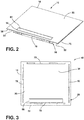
FIG. 2 is a top perspective view of a cooktop assembly, according to the present disclosure; -
FIG. 3 is a bottom plan view of the cooktop assembly ofFIG. 2 ; -
FIG. 4 is a top perspective view of a human-machine interface for a cooktop assembly, according to the present disclosure; -
FIG. 5 is a side perspective cross-sectional view of a cooktop assembly having a human-machine interface, according to the present disclosure; -
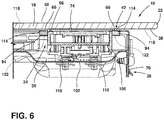
FIG. 6 is a side elevational cross-sectional view of a cooktop assembly having a human-machine interface, according to the present disclosure; -
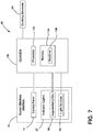
FIG. 7 is a box diagram of an example of a control system of a cooktop assembly, according to the present disclosure; and -
FIG. 8 is a flow diagram of a method for manufacturing a cooktop assembly, according to the present disclosure. - The components in the figures are not necessarily to scale, emphasis instead being placed upon illustrating the principles described herein.
- The present illustrated embodiments reside primarily in combinations of method steps and apparatus components related to a cooktop assembly. Accordingly, the apparatus components and method steps have been represented, where appropriate, by conventional symbols in the drawings, showing only those specific details that are pertinent to understanding the embodiments of the present disclosure so as not to obscure the disclosure with details that will be readily apparent to those of ordinary skill in the art having the benefit of the description herein. Further, like numerals in the description and drawings represent like elements.
- For purposes of description herein, the terms "upper," "lower," "right," "left," "rear," "front," "vertical," "horizontal," and derivatives thereof shall relate to the disclosure as oriented in
FIG. 1 . Unless stated otherwise, the term "front" shall refer to the surface of the element closer to an intended viewer, and the term "rear" shall refer to the surface of the element further from the intended viewer. However, it is to be understood that the disclosure may assume various alternative orientations, except where expressly specified to the contrary. It is also to be understood that the specific devices and processes illustrated in the attached drawings, and described in the following specification are simply exemplary embodiments of the inventive concepts defined in the appended claims. Hence, specific dimensions and other physical characteristics relating to the embodiments disclosed herein are not to be considered as limiting, unless the claims expressly state otherwise. - The terms "including," "comprises," "comprising," or any other variation thereof, are intended to cover a non-exclusive inclusion, such that a process, method, article, or apparatus that comprises a list of elements does not include only those elements but may include other elements not expressly listed or inherent to such process, method, article, or apparatus. An element proceeded by "comprises a ... " does not, without more constraints, preclude the existence of additional identical elements in the process, method, article, or apparatus that comprises the element.
- Referring to
FIGS. 1-8 reference numeral 10 generally designates a cooktop assembly for acooking appliance 14 that includes acooking panel 18 that has afirst edge 22. Asupport feature 26 is coupled to thecooking panel 18 proximate thefirst edge 22. Thecooking panel 18 is disposed on thesupport feature 26. The support feature 26 and thecooking panel 18 define acavity 30. A human-machine interface (HMI) 34 is coupled to anunderside 38 of thecooking panel 18. The HMI 34 is disposed within thecavity 30 and adjacent to thesupport feature 26. Amagnet assembly 42 is coupled to thecooking panel 18 and theHMI 34. Themagnet assembly 42 is configured to retain theHMI 34 in a selected position on theunderside 38 of thecooking panel 18. - Referring to
FIG. 1 , thecooktop assembly 10 is illustrated in combination with thecooking appliance 14. Thecooking appliance 14 is illustrated as an oven having a single cooking cavity. It is contemplated that thecooktop assembly 10 can be combined with anypracticable cooking appliance 14, such as a gas oven, an electric oven, a single oven, a double oven, other similar appliances in residential and commercial settings, and/or combinations thereof. Additionally or alternatively, thecooktop assembly 10 can be a freestanding cooktop disposed on a countertop or other similar structure. - The
cooktop assembly 10 is illustrated as an electric cooktop. In such examples, thecooking panel 18 can be a glass panel, a ceramic panel, and/or a glass-ceramic panel. Thecooktop assembly 10 may be a radiant cooktop or an induction cooktop. In radiant cooktop examples,cooking elements 44 configured as wire coils are disposed below thecooktop assembly 10. When activated by a user, electricity flows to thecooking elements 44 to heat the wire coils. The heat radiates through thecooking panel 18 of thecooktop assembly 10 and into a cooking member (e.g., a pot, a pan, etc.) disposed on thecooktop assembly 10. In induction cooktop examples, thecooking elements 44 are disposed below thecooking panel 18. Thecooking elements 44 each function as a magnet. Thecooking elements 44 generate a magnetic field, which causes the cooking member disposed on thecooking panel 18 to heat. More specifically, electromagnetic energy is transferred to a cooking vessel from thecooking elements 44. There is no thermal energy transfer to the cooking vessel, but instead there is a transfer of electromagnetic energy from thecooking elements 44 which is used to heat the cooking vessel. - Referring still to
FIGS. 1 and2 , thecooking panel 18 includes a plurality ofcooking portions 46 that align with thecooking elements 44 disposed below thecooking panel 18. Thecooking portions 46 may be identified to the user of thecooktop assembly 10 through markings or other identification on atopside 50 of thecooking panel 18. The markings may be advantageous to indicate what portions of thecooking panel 18 may be heated and/or where to place the cooking member. It is contemplated that thecooktop assembly 10 may be another type of cooktop, such as, for example, a gas cooktop, without departing from the teachings herein. - A user-
interface 54 may be disposed proximate thefirst edge 22 of thecooking panel 18. A user can provide an input through the user-interface 54 to control various aspects of thecooktop assembly 10. The user-interface 54 is disposed proximate the front edge (e.g., the first edge 22) of thecooktop assembly 10 providing increased access for the user to control thecooktop assembly 10. The user-interface 54 may be spaced-apart from anycooking elements 44 of thecooktop assembly 10. The user-interface 54 can have any practicable configuration that allows the user to control the operation of thecooktop assembly 10 and/or thecooking appliance 14 without departing from the teachings herein. - The user-
interface 54, as illustrated inFIG. 1 , can be identified to the user via aborder 58.Icons 62 that correspond to various functions of thecooktop assembly 10 can be disposed within theborder 58. Alternatively, one or more of theicons 62 of the user-interface 54 can be disposed on thecooking panel 18 outside of theborder 58. Further, thecooking panel 18 may be free of theborder 58. - Referring to
FIGS. 1-3 , the user-interface 54 extends along thefirst edge 22, which is generally the front edge of thecooking panel 18. Afirst magnet 66 is coupled to theunderside 38 of thecooking panel 18. Thefirst magnet 66 can generally align with theborder 58 on thetopside 50 of thecooking panel 18. Theborder 58 can provide a visual indication of the alignment of the user-interface 54 and thefirst magnet 66. Accordingly, thefirst magnet 66 is disposed proximate thefirst edge 22 of thecooking panel 18. Thefirst magnet 66 may define a shape that corresponds with and matches the shape of theborder 58. - According to various aspects, the
support feature 26 is coupled to theunderside 38 of thecooking panel 18. As illustrated inFIG. 3 , thesupport feature 26 includes a plurality ofelongate members 70. Eachelongate member 70 extends along one of the sides of thecooking panel 18. Accordingly, theelongate member 70 is disposed adjacent to thefirst edge 22 of thecooking panel 18 and thefirst magnet 66. Thesupport feature 26 is configured to engage thecooking appliance 14 to couple thecooktop assembly 10 to thecooking appliance 14. Thecooktop assembly 10 is disposed on and supported by thesupport feature 26. - Referring to
FIGS. 2 and4 , thecooking panel 18 and thesupport feature 26 define thecavity 30 adjacent to theunderside 38 of thecooking panel 18. The cooking elements 44 (FIG. 1 ) can be disposed within thecavity 30 of thecooktop assembly 10. Additionally or alternatively, theHMI 34 can be disposed within thecavity 30. TheHMI 34 includes acontrol panel 74. Thecontrol panel 74 includes selectable features 78 that correspond with various operations of thecooktop assembly 10. In a non-limiting example, thecontrol panel 74 can include buttons or slides. When the buttons or slides (e.g., the selectable features 78) are manipulated, the corresponding operation of thecooktop assembly 10 can be controlled. In another non-limiting example, thecontrol panel 74 may be configured as a touch panel. The touch panel may be, for example, a capacitive touch panel. The capacitive touch panel can be a surface capacitive touch panel, a projected capacitive touch panel, and/or a combination thereof. In such examples, the touch panel can include electrodes arranged in a pattern. Accordingly, the selectable features 78 can correspond with specific locations defined by the electrode pattern of the touch panel. - According to various aspects, the
HMI 34 may include indicator lights 82 disposed on one side or both opposing sides of thecontrol panel 74. In a non-limiting example, the indicator lights 82 can be one or moresegmented LCDs 86.Segmented LCDs 86, also referred to as static displays or glass-only displays, are generally constructed of two pieces of indium tin oxide (ITO) glass with a twisted nematic fluid disposed between the two ITO glass pieces. Each segment of thesegmented LCDs 86 may be one or more lines, segments, and/or symbols that can each be activated and deactivated independently. In certain aspects, the indicator lights 82 may be at least partially configured as a sevensegment LCD 86, which can have seven independently controlled segments configured to display numbers and letters of the alphabet. In examples where the indicator lights 82 form letters of the alphabet, fourteensegment LCDs 86 may be used to provide all 26 letters of the alphabet. In thecooktop assembly 10, thesegmented LCD 86 may be advantageous for displaying numbers for timing cooking operations and conveying similar information to the user. - Additionally or alternatively, the indicator lights 82 may include additional
light sources 90. The additionallight sources 90 may emit visible light that has a wavelength in a range of from about 380 nm to about 740 nm. Thelight sources 90 may include any form of light source, for example, fluorescent lighting, light-emitting diodes LEDs, organic LEDs (OLEDs), polymer LEDs (PLEDs), laser diodes, quantum dot LEDs (QD-LEDs), solid-state lighting, a hybrid, and/or any other similar device. Any other form of lighting may be utilized within thecooktop assembly 10. Further, various types of LEDs are suitable for use as the additionallight sources 90, including, but not limited to, top-emitting LEDs, side-emitting LEDs, and others. Moreover, according to various examples, multicolored light sources such as Red, Green, and Blue (RGB) LEDs that employ red, green, blue LED packaging, which can be used to generate various desired colors of light outputs from a single light source, according to known plate color mixing techniques. The additionallight sources 90 may indicate a status of thecooktop assembly 10, thecooking elements 44, or any other aspect of the cooking appliance 14 (FIG. 1 ). - The indicator lights 82 may be disposed on or otherwise coupled to one or more circuits or circuit boards. In circuit board examples, the one or more circuit boards may be printed circuit boards, which can be configured as flexible or rigid printed circuit boards. In the depicted example of
FIG. 4 , theHMI 34 includes the centrally locatedcontrol panel 74,segmented LCDs 86 disposed on opposing sides of thecontrol panel 74, and additionallight sources 90 disposed adjacent to each of thesegmented LCDs 86. - Referring to
FIGS. 3 and4 , asecond magnet 94 is coupled to atopside 98 of theHMI 34. As illustrated, thesecond magnet 94 defines a rectangular shape that extends around a perimeter of theHMI 34, including thecontrol panel 74 and the indicator lights 82. Thesecond magnet 94 can form any geometric shape, irregular shape, and/or pattern. Thefirst magnet 66 can define a corresponding shape. For example, when thesecond magnet 94 defines a geometric shape (e.g., a rectangle), thefirst magnet 66 may define the same geometric shape (e.g., a rectangle) to mate with thesecond magnet 94. Accordingly, the first magnet defines a shape that is complementary to a shape of thesecond magnet 94. Thefirst magnet 66 is disposed on theunderside 38 of thecooking panel 18. Accordingly, the first andsecond magnets FIG. 5 ) are mating magnets that retain theHMI 34 to theunderside 38 of thecooking panel 18. - Referring to
FIGS. 5 and6 , theHMI 34 is disposed adjacent to theunderside 38 of thecooking panel 18 within thecavity 30. TheHMI 34 is disposed adjacent to theelongate member 70 proximate thefirst edge 22 of thecooking panel 18. Aninterior panel 102 may at least partially define thecavity 30. Theinterior panel 102 may be substantially parallel to thecooking panel 18. TheHMI 34 can extend between thecooking panel 18 and theinterior panel 102. Theinterior panel 102 may be coupled to thesupport feature 26. As illustrated inFIG. 6 , theelongate member 70 is disposed proximate thefirst edge 22 of thecooking panel 18 and is mechanically fastened to theinterior panel 102. - The HMI can include a base 106 with the
control panel 74 and/or the indicator lights 82 (FIG. 4 ) disposed on thebase 106. Thebase 106 extends between thecooking panel 18 and theinterior panel 102. According to various aspects, theHMI 34 can include biasingmembers 110 configured to resiliently support theHMI 34. The biasingmembers 110 may extend through theinterior panel 102 with portions of the biasingmembers 110 disposed within thecavity 30 on a first side of theinterior panel 102 and a portion of the biasingmembers 110 disposed outside thecavity 30 on the opposing side of theinterior panel 102. The biasingmembers 110 may be configured to bias theHMI 34 toward thecooking panel 18, such that theHMI 34 abuts theunderside 38 of thecooking panel 18. - Referring still to
FIGS. 5 and6 , themagnet assembly 42 is coupled to both thecooking panel 18 and theHMI 34. Themagnet assembly 42 is configured to retain theHMI 34 in a selected position on theunderside 38 of thecooking panel 18. Thefirst magnet 66 of themagnet assembly 42 is coupled to theunderside 38 of thecooking panel 18. Thesecond magnet 94 of themagnet assembly 42 can be coupled to theHMI 34. Thesecond magnet 94 can extend around the perimeter of theHMI 34, thereby extending around, thecontrol panel 74 and the indicator lights 82. As illustrated, thesecond magnet 94 may be directly coupled to thebase 106 of theHMI 34 adjacent to thecontrol panel 74. Thesecond magnet 94 may be substantially flush with a top of thebase 106. Thefirst magnet 66 can extend from theunderside 38 of thecooking panel 18 to mate with thesecond magnet 94. Thecontrol panel 74 on thebase 106 may be disposed adjacent to amating interface 114 between thefirst magnet 66 and thesecond magnet 94. Accordingly, thecontrol panel 74 can be disposed between two opposing portions of thefirst magnet 66 and may abut theunderside 38 of thecooking panel 18. - The
first magnet 66 may be a magnetic member coupled directly to theunderside 38 of thecooking panel 18. Alternatively, afilm layer 118 may be disposed on theunderside 38 of thecooking panel 18. According to various aspects, thefirst magnet 66 may be included and/or embedded in thefilm layer 118. Thefilm layer 118 may be a plastic film, such that thefirst magnet 66 can be laminated to theunderside 38 of thecooking panel 18. - The
second magnet 94 can be a magnetic component coupled directly to theHMI 34. Alternatively, afilm cover 122 may be disposed on thetopside 98 of theHMI 34. Thesecond magnet 94 can be included and/or embedded within thefilm cover 122. Thefilm cover 122 may be a plastic film, such that thesecond magnet 94 may be laminated to theHMI 34. The magnetic forces between thefirst magnet 66 and thesecond magnet 94 may be of a sufficient strength to retain theHMI 34 to thecooking panel 18 through thefilm layer 118 and/or thefilm cover 122. - In an additional or alternative non-limiting example, one or both of the
first magnet 66 and thesecond magnet 94 can be included in an insert. The insert can be coupled to thecooking panel 18 and/or theHMI 34, respectively. It is contemplated that the inserts can be fixedly coupled to each of thecooking panel 18 and theHMI 34, or alternatively may be removably coupled to thecooking panel 18 and theHMI 34. In such examples, thefirst magnet 66 can mate with thesecond magnet 94 through one or both inserts. - Referring to
FIGS. 1-6 , themagnet assembly 42 can retain theHMI 34 in the selected position on theunderside 38 of thecooking panel 18. The selected position of theHMI 34 is configured to align the selectable features 78 of thecontrol panel 74 with theicons 62 on thetopside 50 of thecooking panel 18. Accordingly, the selected position of theHMI 34 may provide increased reliability for the user interacting with the user-interface 54 on thetopside 50 of thecooking panel 18. - Referring to
FIG. 7 , thecooktop assembly 10 can include acontroller 126 in communication with theHMI 34 and thecooking elements 44. Thecontroller 126 includes aprocessor 130, amemory 134, and other control circuitry.Routines 138 are stored in thememory 134 and executable by theprocessor 130. One ormore routines 138 can relate to operations of thecooking elements 44. Additionally, one ormore routines 138 can relate to controlling the indicator lights 82, including the segmentedLCDs 86 and thelight sources 90. - With reference now to
FIGS. 1-7 , in use, the user can touch, press, or otherwise interact with a selectedicon 62 on thetopside 50 of thecooking panel 18. The interaction with theicon 62 can be detected by thecontrol panel 74. The selectedicon 62 may correspond with one or more of the selectable features 78 of thecontrol panel 74. Thecontrol panel 74 can send a signal to thecontroller 126 in response to the selection of theicon 62. Thecontroller 126 can send a corresponding signal to therespective cooking element 44 or otherwise control the operation of thecooktop assembly 10. Accordingly, theHMI 34 is configured to receive a user selection through thecooking panel 18. - Referring to
FIG. 8 , and with further reference toFIGS. 1-7 , amethod 200 of manufacturing thecooktop assembly 10 includesstep 204 of applying thefilm layer 118 to theunderside 38 of thecooking panel 18. Thefilm layer 118 may include thefirst magnet 66 of themagnet assembly 42. Step 204 may also include coupling thefirst magnet 66 directly to theunderside 38 of thecooking panel 18. Instep 208, thefilm cover 122 may be applied to thetopside 98 of theHMI 34. Thefilm cover 122 may include thesecond magnet 94. Step 208 may also include directly coupling thesecond magnet 94 to theHMI 34. - In
step 212, thefirst magnet 66 can be aligned with thesecond magnet 94. Generally, the first andsecond magnets first magnet 66 and thesecond magnet 94 mate and engage one another when aligned. It is advantageous to fully align thefirst magnet 66 with thesecond magnet 94 to increase the surface area of themating interface 114. Accordingly, the more accurate the alignment between thefirst magnet 66 and thesecond magnet 94, the greater the strength in the engagement between thefirst magnet 66 andsecond magnet 94. - In
step 216, theselectable feature 78 of thecontrol panel 74 can be aligned with theicons 62 on thetopside 50 of thecooking panel 18. TheHMI 34 receives the user selection via an interaction between the selectedicon 62 and the selectable features 78 of thecontrol panel 74. Accordingly, proper alignment between theicon 62 and theselectable feature 78 increases the accuracy and reliability of thecooktop assembly 10. - In
step 220, theHMI 34 may be coupled with thecooking panel 18 by engaging thesecond magnet 94 with thefirst magnet 66. In various examples, themagnet assembly 42 may also be coupled to thesupport feature 26, as best illustrated inFIG. 6 . Theelongate member 70 disposed proximate thefirst edge 22 may extend between thefirst magnet 66 and thesecond magnet 94. Themagnet assembly 42 can magnetically engage thesupport feature 26. Additionally or alternatively, each of thefirst magnet 66 and thesecond magnet 94 can define a notch to accommodate thesupport feature 26. The engagement of themagnet assembly 42 with thesupport feature 26 may assist in maintaining the proper alignment of theHMI 34 with thecooking panel 18. Themagnet assembly 42 can retain theHMI 34 in the selected position on theunderside 38 of thecooking panel 18. - Use of the present disclosure may provide for a variety of advantages. For example, the
magnet assembly 42 can retain theHMI 34 on theunderside 38 of thecooking panel 18. Themagnet assembly 42 can provide proper alignment between theselectable features 78 of theHMI 34 with theicons 62 that are engaged by the user. Further, themagnet assembly 42 can increase the reliability of the operation of thecooktop assembly 10 through the alignment of theicons 62 with theHMI 34. Additionally, themagnet assembly 42 can provide a flexible arrangement for coupling theHMI 34 to thecooking panel 18 that may be free of fixed mechanical attachments. Also, themagnet assembly 42 may accommodate variations in component dimension tolerances. Moreover, themagnet assembly 42 may reduce manufacturing and production costs and time as theHMI 34 can be coupled to thecooking panel 18 manually, in a semi-automatic assembly line, and/or in an automatic assembly line. Further, themagnet assembly 42 can be applied directly to thecooking panel 18 and can provide an abutting relationship between thecontrol panel 74 of theHMI 34 and thecooking panel 18. Additional benefits or advantages of using this device may also be realized and/or achieved. - According to an aspect of the present disclosure, a cooktop for a cooking appliance includes a cooking panel that has a first edge. A support feature is coupled to the cooking panel proximate the first edge. The cooking panel is disposed on the support feature. The support feature and the cooking panel define a cavity. A human-machine interface is coupled to an underside of the cooking panel. The human-machine interface is disposed within the cavity and adjacent to the support feature. A magnet assembly is coupled to the cooking panel and the human-machine interface. The magnet assembly is configured to retain the human-machine interface in a selected position on the underside of the cooking panel.
- According to another aspect, a magnet assembly includes a first magnet coupled to an underside of a cooking panel and a second magnet coupled to a topside of a human-machine interface.
- According to still another aspect, a second magnet extends around a perimeter of a human-machine interface.
- According to yet another aspect, a second magnet forms a shape that is complementary to a shape of a first magnet.
- According to another aspect, a human-machine interface includes a touch panel and indicator lights disposed on opposing sides of the touch panel.
- According to still another aspect, a magnet assembly extends around indicator lights and a touch panel.
- According to yet another aspect, a cooking panel is one of a glass panel, a ceramic panel, and a glass-ceramic panel.
- According to another aspect, a human-machine interface is a touch panel configured to receive a user selection through a cooking panel.
- According to still another aspect, a magnet assembly is embedded in at least one of a film layer coupled to a cooking panel and a film cover coupled to a human-machine interface.
- According to another aspect of the present disclosure, a cooktop assembly includes a cooking panel having a topside and an underside. A first magnet is coupled to the underside of the cooking panel. A human-machine interface has selectable features. The human-machine interface is disposed proximate the underside of the cooking panel. A second magnet is coupled to the human-machine interface. The second magnet is configured to mate with the first magnet to couple the human-machine interface to the cooking panel.
- According to another aspect, a film layer is coupled to the underside of the cooking panel. A first magnet is included in the film layer.
- According to still another aspect, a film cover is disposed on a topside of the human-machine interface. A second magnet is embedded within the film cover.
- According to yet another aspect, a touch panel of a human-machine interface abuts an underside of a cooking panel.
- According to another aspect, a touch panel is disposed adjacent to a mating interface between a first magnet and a second magnet.
- According to still another aspect, a support feature is disposed proximate a front edge of the cooking panel. The support feature is coupled to a second magnet.
- According to yet another aspect, a second magnet extends around a perimeter of a human-machine interface.
- According to another aspect, a second magnet defines a shape that is complementary to a shape of a first magnet.
- According to still another aspect, a cooking panel includes icons on a topside thereof that correspond and align with selectable features of a human-machine interface.
- According to another aspect of the present disclosure, a method of manufacturing a cooktop assembly includes applying a film layer to an underside of a cooking panel. The film layer includes a first magnet. A film cover is applied to a topside of a human-machine interface. The film cover includes a second magnet. The second magnet is aligned with the first magnet. The human-machine interface is coupled to the cooking panel by engaging the second magnet with the first magnet.
- According to still another aspect, selectable features of a human-machine interface are aligned with icons on a cooking panel.
Claims (15)
- A cooktop (10) for a cooking appliance (14), comprising:a cooking panel (18) having a first edge (22);a support feature (26) coupled to the cooking panel (18) proximate the first edge (22), wherein the cooking panel (18) is disposed on the support feature (26), and wherein the support feature (26) and the cooking panel (18) define a cavity (30);a human-machine interface (34) coupled to an underside (38) of the cooking panel (18), wherein the human-machine interface (34) is disposed within the cavity (30) and adjacent to the support feature (26); anda magnet assembly (42) coupled to the cooking panel (18) and the human-machine interface (34), wherein the magnet assembly (42) is configured to retain the human-machine interface (34) in a selected position on the underside (38) of the cooking panel (18).
- The cooktop (10) of claim 1, wherein the magnet assembly (42) includes a first magnet (66) coupled to the underside (38) of the cooking panel (18) and a second magnet (94) coupled to a topside (98) of the human-machine interface (34).
- The cooktop (10) of claim 2, wherein the second magnet (94) extends around a perimeter of the human-machine interface (34).
- The cooktop (10) of either of claim 1 or claim 2, wherein the second magnet (94) forms a shape that is complementary to a shape of the first magnet (66).
- The cooktop (10) of any one of claims 1-4, wherein the human-machine interface (38) includes a touch panel and indicator lights (82) disposed on opposing sides of the touch panel.
- The cooktop (10) of claim 5, wherein the magnet assembly (42) extends around the indicator lights (82) and the touch panel.
- The cooktop (10) of any one of claims 1-6, wherein the cooking panel (18) is one of a glass panel, a ceramic panel, and a glass-ceramic panel.
- The cooktop (10) of any one of claims 1-7, wherein the human-machine interface (42) is a touch panel configured to receive a user selection through the cooking panel (18).
- The cooktop (10) of any one of claims 1-8, wherein the magnet assembly (42) is embedded in at least one of a film layer (118) coupled to the cooking panel (18) and a film cover (122) coupled to the human-machine interface (34).
- The cooktop (10) of claim 9, wherein the film layer (118) is coupled to the underside (38) of the cooking panel (18), wherein a first magnet (66) of the magnet assembly (44) is embedded in the film layer (118).
- The cooktop (10) of either of claim 9 or claim 10, wherein the film cover (122) is disposed on the topside (98) of the human-machine interface (34), wherein a second magnet (94) of the magnet assembly (42) is embedded within the film cover (122).
- The cooktop (10) of any one of claims 1-11, wherein a touch panel of the human-machine interface (34) abuts and the underside (38) of the cooking panel (18).
- The cooktop (10) of any one of claims 1-12, wherein the cooking panel (18) includes icons on the topside (98) thereof that correspond and align with selectable features (78) of the human-machine interface (34).
- The cooktop (10) of any one of claims 1-13, wherein the first edge (22) of the cooking panel (18) is a front edge of the cooking panel (18), and wherein the support feature (26) is coupled to the magnet assembly (42).
- A method (200) of manufacturing the cooktop (10) of any one of claims 1-14, comprising:applying the film layer (118) (204) to the underside (38) of the cooking panel (18), wherein the film layer (118) includes a first magnet (66);applying the film cover (122) (208) to a topside (98) of the human-machine interface (34), wherein the film cover (122) includes a second magnet (94);aligning the second magnet (94) (212) with the first magnet (66); andcoupling the human-machine interface (34) to the cooking panel (18) (220) by engaging the second magnet (94) with the first magnet (66).
Applications Claiming Priority (1)
| Application Number | Priority Date | Filing Date | Title |
|---|---|---|---|
| US16/886,223 US11708976B2 (en) | 2020-05-28 | 2020-05-28 | Cooktop assembly |
Publications (1)
| Publication Number | Publication Date |
|---|---|
| EP3916307A1 true EP3916307A1 (en) | 2021-12-01 |
Family
ID=76059764
Family Applications (1)
| Application Number | Title | Priority Date | Filing Date |
|---|---|---|---|
| EP21175312.4A Withdrawn EP3916307A1 (en) | 2020-05-28 | 2021-05-21 | Cooktop assembly |
Country Status (2)
| Country | Link |
|---|---|
| US (1) | US11708976B2 (en) |
| EP (1) | EP3916307A1 (en) |
Citations (3)
| Publication number | Priority date | Publication date | Assignee | Title |
|---|---|---|---|---|
| EP2658341A2 (en) * | 2012-04-27 | 2013-10-30 | BSH Bosch und Siemens Hausgeräte GmbH | System with a cooking plate and with at least one removable cooking plate |
| US20190090629A1 (en) * | 2016-04-25 | 2019-03-28 | Eurokera S.N.C. | Glass ceramic plate for worktop or furniture |
| DE202019005361U1 (en) * | 2018-11-30 | 2020-05-07 | Eurokera S.N.C. | Glass ceramic articles |
Family Cites Families (12)
| Publication number | Priority date | Publication date | Assignee | Title |
|---|---|---|---|---|
| DE19849075A1 (en) | 1998-10-24 | 2000-04-27 | Ego Elektro Geraetebau Gmbh | Operating control for electric cooking hob or oven uses hand-held remote-control device for transmission of control and regulation signals |
| DE19959224B4 (en) | 1999-12-08 | 2010-07-01 | E.G.O. Elektro-Gerätebau GmbH | System consisting of an electric cooking appliance and a separate operating unit |
| US20050008458A1 (en) * | 2003-05-30 | 2005-01-13 | Keech Nancy Kay | Biased fastening system |
| DE102006028889B3 (en) | 2006-06-21 | 2007-07-12 | Miele & Cie. Kg | Domestic appliance, e.g. cooker or washing machine, has replaceable labeling field in the form of magnetizable or magnetic plate retained on operating panel |
| DE102007016466B3 (en) | 2007-03-16 | 2008-08-21 | E.G.O. Elektro-Gerätebau GmbH | Operating device for use in hob, has sensor unit e.g. hall-sensor and optical distance sensor, laterally arranged in movement section of signal unit, where operating device is formed without internal energy supply |
| US7843295B2 (en) * | 2008-04-04 | 2010-11-30 | Cedar Ridge Research Llc | Magnetically attachable and detachable panel system |
| US8373527B2 (en) * | 2008-04-04 | 2013-02-12 | Correlated Magnetics Research, Llc | Magnetic attachment system |
| US8835814B2 (en) | 2008-10-02 | 2014-09-16 | Bsh Bosch Und Siemens Hausgeraete Gmbh | Domestic appliance device |
| EP2260751A1 (en) | 2009-06-10 | 2010-12-15 | Electrolux Home Products Corporation N.V. | Domestic appliance |
| DE102009045129A1 (en) | 2009-09-29 | 2011-03-31 | BSH Bosch und Siemens Hausgeräte GmbH | Domestic appliance device |
| DE102010039390A1 (en) | 2010-08-17 | 2012-02-23 | BSH Bosch und Siemens Hausgeräte GmbH | Hob device |
| FR3050366B1 (en) | 2016-04-25 | 2018-11-02 | Eurokera S.N.C. | VITROCERAMIC PLATE FOR PLAN WORK OR FURNITURE |
-
2020
- 2020-05-28 US US16/886,223 patent/US11708976B2/en active Active
-
2021
- 2021-05-21 EP EP21175312.4A patent/EP3916307A1/en not_active Withdrawn
Patent Citations (3)
| Publication number | Priority date | Publication date | Assignee | Title |
|---|---|---|---|---|
| EP2658341A2 (en) * | 2012-04-27 | 2013-10-30 | BSH Bosch und Siemens Hausgeräte GmbH | System with a cooking plate and with at least one removable cooking plate |
| US20190090629A1 (en) * | 2016-04-25 | 2019-03-28 | Eurokera S.N.C. | Glass ceramic plate for worktop or furniture |
| DE202019005361U1 (en) * | 2018-11-30 | 2020-05-07 | Eurokera S.N.C. | Glass ceramic articles |
Also Published As
| Publication number | Publication date |
|---|---|
| US20210372628A1 (en) | 2021-12-02 |
| US11708976B2 (en) | 2023-07-25 |
Similar Documents
| Publication | Publication Date | Title |
|---|---|---|
| US10666253B2 (en) | Backlighting appliance deadfronted user interfaces | |
| EP2395813B1 (en) | Induction heating cooker and control method thereof | |
| CN111543121B (en) | Electromagnetic heating furnace and control display method thereof | |
| JP5022277B2 (en) | Induction heating cooker | |
| EP2392859B1 (en) | Cooktop-interface, cooktop-panel, cooking device and method of operating a cooktop-interface | |
| EP3226653A1 (en) | Induction heating device and method of controlling the same | |
| CN105051460B (en) | Cooking hob and its operating method including user interface | |
| EP1596635A4 (en) | Induction heating cooler | |
| KR100851460B1 (en) | Heating cooking apparatus | |
| CN114999320B (en) | Display assembly, household appliance and control method | |
| CN114999406B (en) | Display control component, household appliance and control method | |
| US11708976B2 (en) | Cooktop assembly | |
| EP2087288B1 (en) | Cooking device and interface unit for the cooking device | |
| EP1760516B1 (en) | Liquid crystal display device | |
| CN101535723B (en) | Cooking device and interface unit for the cooking device | |
| TWM363641U (en) | Capacitive touch input device | |
| JP3382904B2 (en) | Liquid crystal display | |
| JP2005322511A (en) | Cooker | |
| CN210628312U (en) | Display panel and display device | |
| EP4648552A1 (en) | Cooking apparatus | |
| JP2007194100A (en) | Cooker | |
| CN209708545U (en) | Touch-control display component | |
| CN119311143A (en) | Display module, display device and electrical appliance with touch function | |
| EP3372053B1 (en) | Induction cooker with improved usability | |
| CN119336192A (en) | A low-cost touch color screen and a temperature controller using the same |
Legal Events
| Date | Code | Title | Description |
|---|---|---|---|
| PUAI | Public reference made under article 153(3) epc to a published international application that has entered the european phase |
Free format text: ORIGINAL CODE: 0009012 |
|
| STAA | Information on the status of an ep patent application or granted ep patent |
Free format text: STATUS: THE APPLICATION HAS BEEN PUBLISHED |
|
| AK | Designated contracting states |
Kind code of ref document: A1 Designated state(s): AL AT BE BG CH CY CZ DE DK EE ES FI FR GB GR HR HU IE IS IT LI LT LU LV MC MK MT NL NO PL PT RO RS SE SI SK SM TR |
|
| B565 | Issuance of search results under rule 164(2) epc |
Effective date: 20211029 |
|
| STAA | Information on the status of an ep patent application or granted ep patent |
Free format text: STATUS: THE APPLICATION IS DEEMED TO BE WITHDRAWN |
|
| 18D | Application deemed to be withdrawn |
Effective date: 20220602 |