EP3916303A1 - Multi-walled structure for a gas turbine engine - Google Patents
Multi-walled structure for a gas turbine engine Download PDFInfo
- Publication number
- EP3916303A1 EP3916303A1 EP21175625.9A EP21175625A EP3916303A1 EP 3916303 A1 EP3916303 A1 EP 3916303A1 EP 21175625 A EP21175625 A EP 21175625A EP 3916303 A1 EP3916303 A1 EP 3916303A1
- Authority
- EP
- European Patent Office
- Prior art keywords
- wall
- hot wall
- hot
- cold
- apertures
- Prior art date
- Legal status (The legal status is an assumption and is not a legal conclusion. Google has not performed a legal analysis and makes no representation as to the accuracy of the status listed.)
- Granted
Links
Images







Classifications
-
- F—MECHANICAL ENGINEERING; LIGHTING; HEATING; WEAPONS; BLASTING
- F23—COMBUSTION APPARATUS; COMBUSTION PROCESSES
- F23R—GENERATING COMBUSTION PRODUCTS OF HIGH PRESSURE OR HIGH VELOCITY, e.g. GAS-TURBINE COMBUSTION CHAMBERS
- F23R3/00—Continuous combustion chambers using liquid or gaseous fuel
- F23R3/005—Combined with pressure or heat exchangers
-
- F—MECHANICAL ENGINEERING; LIGHTING; HEATING; WEAPONS; BLASTING
- F23—COMBUSTION APPARATUS; COMBUSTION PROCESSES
- F23R—GENERATING COMBUSTION PRODUCTS OF HIGH PRESSURE OR HIGH VELOCITY, e.g. GAS-TURBINE COMBUSTION CHAMBERS
- F23R3/00—Continuous combustion chambers using liquid or gaseous fuel
- F23R3/02—Continuous combustion chambers using liquid or gaseous fuel characterised by the air-flow or gas-flow configuration
- F23R3/04—Air inlet arrangements
- F23R3/06—Arrangement of apertures along the flame tube
- F23R3/08—Arrangement of apertures along the flame tube between annular flame tube sections, e.g. flame tubes with telescopic sections
-
- F—MECHANICAL ENGINEERING; LIGHTING; HEATING; WEAPONS; BLASTING
- F02—COMBUSTION ENGINES; HOT-GAS OR COMBUSTION-PRODUCT ENGINE PLANTS
- F02C—GAS-TURBINE PLANTS; AIR INTAKES FOR JET-PROPULSION PLANTS; CONTROLLING FUEL SUPPLY IN AIR-BREATHING JET-PROPULSION PLANTS
- F02C7/00—Features, components parts, details or accessories, not provided for in, or of interest apart form groups F02C1/00 - F02C6/00; Air intakes for jet-propulsion plants
- F02C7/12—Cooling of plants
- F02C7/16—Cooling of plants characterised by cooling medium
- F02C7/18—Cooling of plants characterised by cooling medium the medium being gaseous, e.g. air
-
- F—MECHANICAL ENGINEERING; LIGHTING; HEATING; WEAPONS; BLASTING
- F23—COMBUSTION APPARATUS; COMBUSTION PROCESSES
- F23R—GENERATING COMBUSTION PRODUCTS OF HIGH PRESSURE OR HIGH VELOCITY, e.g. GAS-TURBINE COMBUSTION CHAMBERS
- F23R3/00—Continuous combustion chambers using liquid or gaseous fuel
- F23R3/002—Wall structures
-
- F—MECHANICAL ENGINEERING; LIGHTING; HEATING; WEAPONS; BLASTING
- F23—COMBUSTION APPARATUS; COMBUSTION PROCESSES
- F23R—GENERATING COMBUSTION PRODUCTS OF HIGH PRESSURE OR HIGH VELOCITY, e.g. GAS-TURBINE COMBUSTION CHAMBERS
- F23R3/00—Continuous combustion chambers using liquid or gaseous fuel
- F23R3/02—Continuous combustion chambers using liquid or gaseous fuel characterised by the air-flow or gas-flow configuration
- F23R3/04—Air inlet arrangements
- F23R3/06—Arrangement of apertures along the flame tube
-
- F—MECHANICAL ENGINEERING; LIGHTING; HEATING; WEAPONS; BLASTING
- F23—COMBUSTION APPARATUS; COMBUSTION PROCESSES
- F23R—GENERATING COMBUSTION PRODUCTS OF HIGH PRESSURE OR HIGH VELOCITY, e.g. GAS-TURBINE COMBUSTION CHAMBERS
- F23R3/00—Continuous combustion chambers using liquid or gaseous fuel
- F23R3/42—Continuous combustion chambers using liquid or gaseous fuel characterised by the arrangement or form of the flame tubes or combustion chambers
- F23R3/44—Combustion chambers comprising a single tubular flame tube within a tubular casing
-
- F—MECHANICAL ENGINEERING; LIGHTING; HEATING; WEAPONS; BLASTING
- F23—COMBUSTION APPARATUS; COMBUSTION PROCESSES
- F23R—GENERATING COMBUSTION PRODUCTS OF HIGH PRESSURE OR HIGH VELOCITY, e.g. GAS-TURBINE COMBUSTION CHAMBERS
- F23R2900/00—Special features of, or arrangements for continuous combustion chambers; Combustion processes therefor
- F23R2900/03041—Effusion cooled combustion chamber walls or domes
-
- F—MECHANICAL ENGINEERING; LIGHTING; HEATING; WEAPONS; BLASTING
- F23—COMBUSTION APPARATUS; COMBUSTION PROCESSES
- F23R—GENERATING COMBUSTION PRODUCTS OF HIGH PRESSURE OR HIGH VELOCITY, e.g. GAS-TURBINE COMBUSTION CHAMBERS
- F23R2900/00—Special features of, or arrangements for continuous combustion chambers; Combustion processes therefor
- F23R2900/03044—Impingement cooled combustion chamber walls or subassemblies
-
- Y—GENERAL TAGGING OF NEW TECHNOLOGICAL DEVELOPMENTS; GENERAL TAGGING OF CROSS-SECTIONAL TECHNOLOGIES SPANNING OVER SEVERAL SECTIONS OF THE IPC; TECHNICAL SUBJECTS COVERED BY FORMER USPC CROSS-REFERENCE ART COLLECTIONS [XRACs] AND DIGESTS
- Y02—TECHNOLOGIES OR APPLICATIONS FOR MITIGATION OR ADAPTATION AGAINST CLIMATE CHANGE
- Y02T—CLIMATE CHANGE MITIGATION TECHNOLOGIES RELATED TO TRANSPORTATION
- Y02T50/00—Aeronautics or air transport
- Y02T50/60—Efficient propulsion technologies, e.g. for aircraft
Definitions
- This disclosure (invention) relates generally to a gas turbine engine and, more particularly, to a multi-walled structure in the gas turbine engine.
- a gas turbine engine combustor may include a combustor wall with a dual-walled structure.
- This dual-walled structure typically includes a shell supporting a heat shield (also referred to as a "liner").
- the shell may include an array of impingement apertures and the heat shield may include an array of effusion apertures.
- the impingement apertures are provided to impingement cool a backside of the heat shield.
- the effusion apertures are also provided to cool the heat shield by facilitating convection within the heat shield (e.g., as cooling air passes through the effusion apertures) as well as film cooling a hot side of the heat shield.
- Such a dual-wall structure is configured such that a pressure drop across the shell is greater than a pressure drop across the heat shield.
- an assembly for a gas turbine engine.
- This assembly includes a multi-walled structure including a cold wall, a hot wall and a cooling cavity vertically between the cold wall and the hot wall.
- the cold wall includes a plurality of cold wall apertures fluidly coupled with the cooling cavity.
- the cold wall apertures are configured to subject the cold wall to a cold wall pressure drop vertically across the cold wall.
- the hot wall includes a plurality of hot wall apertures fluidly coupled with the cooling cavity.
- the hot wall apertures are configured to subject the hot wall to a hot wall pressure drop vertically across the hot wall that is greater than or equal to the cold wall pressure drop.
- this assembly includes a multi-walled structure including a cold wall, a hot wall and a cooling cavity between the cold wall and the hot wall.
- the cold wall includes a plurality of cold wall apertures fluidly coupled with the cooling cavity.
- the cold wall apertures provide the cold wall with a first percentage of open area.
- the hot wall includes a plurality of hot wall apertures fluidly coupled with the cooling cavity.
- the hot wall apertures provide the hot wall with a second percentage of open area that is less than the first percentage of open area.
- this assembly includes a multi-walled structure including a cold wall, a hot wall and a cooling cavity between and formed by the cold wall and the hot wall.
- the cold wall includes a plurality of cold wall apertures fluidly coupled with the cooling cavity.
- the cold wall apertures include a first cold wall aperture that extends through the cold wall along a cold wall aperture centerline that is angularly offset from an interior surface of the cold wall by an acute angle.
- the hot wall includes a plurality of hot wall apertures fluidly coupled with the cooling cavity.
- the hot wall apertures include a first hot wall aperture that extends through the hot wall along a hot wall aperture centerline with a tortuous trajectory.
- a longitudinal length of the first hot wall aperture along the hot wall aperture centerline may be greater than a thickness of the hot wall and/or less than or equal to twenty times the thickness of the hot wall.
- At least a portion of the cold wall aperture centerline that extends to an interior surface of the cold wall defining the cooling cavity may have a cold wall aperture centerline trajectory with a component in a first direction and a component in a second direction.
- At least a portion of the hot wall aperture centerline that extends from an interior surface of the hot wall defining the cooling cavity may have a hot wall aperture centerline trajectory with a component in the first direction and a component in the second direction.
- the multi-walled structure may be configured such that the cold wall pressure drop is equal to between five percent and forty-five percent of a total pressure drop vertically across the multi-walled structure.
- the multi-walled structure may be configured such that the hot wall pressure drop is equal to between fifty-five percent and ninety five percent of a total pressure drop vertically across the multi-walled structure.
- the hot wall pressure drop may be at least one and one-quarter times the cold wall pressure drop.
- the cold wall apertures may include an impingement aperture configured to direct a jet of cooling fluid to impinge against the hot wall.
- the cold wall apertures may include a first cold wall aperture that extends through the cold wall along a cold wall aperture centerline.
- the cold wall aperture centerline may be angularly offset from an interior surface of the cold wall by an acute angle.
- the hot wall apertures may include an effusion aperture configured to direct cooling fluid out of the cooling cavity into a plenum and along an exterior surface of the hot wall.
- the hot wall apertures may include a first hot wall aperture that extends through the hot wall along a hot wall aperture centerline with a tortuous trajectory.
- a longitudinal length of the first hot wall aperture along the hot wall aperture centerline may be greater than a thickness of the hot wall.
- the cold wall apertures may include a first cold wall aperture that extends through the cold wall along a cold wall aperture centerline. At least a portion of the cold wall aperture centerline that extends to an interior surface of the cold wall defining the cooling cavity may have a trajectory with a component in a first direction and a component in a vertical direction.
- the hot wall apertures may include a first hot wall aperture that extends through the hot wall along a hot wall aperture centerline. At least a portion of the hot wall aperture centerline that extends from an interior surface of the hot wall defining the cooling cavity may have a trajectory with a component in the first direction and a component in the vertical direction.
- the cold wall apertures may include a first cold wall aperture that extends through the cold wall along a cold wall aperture centerline. At least a portion of the cold wall aperture centerline that extends to an interior surface of the cold wall defining the cooling cavity may have a trajectory with a component in a first direction and a component in a vertical direction.
- the hot wall apertures may include a first hot wall aperture that extends through the hot wall along a hot wall aperture centerline. At least a portion of the hot wall aperture centerline that extends from an interior surface of the hot wall defining the cooling cavity may have a trajectory with a component in a second direction and a component in the vertical direction. The second direction may be different from the first direction.
- the hot wall apertures may include a first hot wall aperture with a diffusion outlet portion.
- the cold wall apertures may include a first cold wall aperture with a first diameter.
- the hot wall apertures may include a first hot wall aperture with a second diameter that is less than the first diameter.
- the cold wall and/or the cold wall apertures may only include a first quantity of cold wall apertures.
- the hot wall and/or the hot wall apertures may only include a second quantity of hot wall apertures that is less than the first quantity of cold wall apertures.
- the cold wall may be configured with a first percentage of open area to the cooling cavity.
- the hot wall may be configured with a second percentage of open area from the cooling cavity that is less than the first percentage of open area.
- the assembly may also include a combustor of the gas turbine engine.
- the combustor may include the multi-walled structure.
- the present disclosure may include any one or more of the individual features disclosed above and/or below alone or in any combination thereof.
- FIG. 1 illustrates an assembly 30 for a gas turbine engine.
- This turbine engine assembly 30 includes a multi-walled structure 32 such as, for example, a hollow dual-walled structure.
- the multi-walled structure 32 is described below as a wall of a combustor of the gas turbine engine. The present disclosure, however, is not limited to such an exemplary combustor application.
- the multi-walled structure 32 may alternatively be configured as a duct wall, an airfoil wall, a vane wall, a case wall, a platform or any other multi-walled structure (e.g., wall structure with internal cooling) within the gas turbine engine.
- the multi-walled structure 32 of FIG. 1 includes a cold wall 34 and a hot wall 36.
- the multi-walled structure 32 also includes one or more internal cooling cavities 38.
- cold wall may describe herein a wall portion of the multi-walled structure 32 that is subject to relatively low temperatures during operation of the turbine engine assembly 30.
- the cold wall 34 may be configured as an exterior wall (also sometimes referred to as a "shell") of a combustor wall.
- the cold wall 34 may be configured as an interior wall of an airfoil wall or a vane wall.
- the cold wall 34 of FIG. 2 extends circumferentially about (e.g., completely around) an axial centerline 40 of the turbine engine assembly 30; e.g., a rotational axis and/or centerline axis of the gas turbine engine.
- This cold wall 34 may be configured as a monolithic full hoop body.
- the cold wall 34 may be configured from one or more segments; e.g., a pair of arcuate halves. Referring to FIG.
- the cold wall 34 extends longitudinally (e.g., generally axially along the axial centerline 40) between and to a cold wall first (e.g., forward / upstream) end 42 and a cold wall second (e.g., aft / downstream) end 44.
- the cold wall 34 has a vertical thickness that extends vertically (e.g., generally radially relative to the axial centerline 40) between and to a cold wall exterior side 46 and a cold wall interior side 48.
- the cold wall 34 may be constructed from or otherwise include metal.
- This metal may include, but is not limited to, nickel (Ni), aluminum (Al), titanium (Ti), steel, etc.
- Ni nickel
- Al aluminum
- Ti titanium
- the present disclosure is not limited to the foregoing exemplary cold wall materials, nor to metal cold walls.
- hot wall describes herein a wall portion of the multi-walled structure 32 that is subject to relatively high temperatures during operation of the turbine engine assembly 30.
- the hot wall 36 may be configured as an interior wall (also sometimes referred to as a "heat shield” or a "liner") of a combustor wall.
- the hot wall 36 may be configured as an exterior wall of an airfoil wall or a vane wall.
- the hot wall 36 of FIG. 3 extends circumferentially about (e.g., completely around) the axial centerline 40. Referring to FIG. 1 , the hot wall 36 extends longitudinally (e.g., generally axially along the axial centerline 40) between and to a hot wall first (e.g., forward / upstream) end 50 and a hot wall second (e.g., aft / downstream) end 52.
- a hot wall first (e.g., forward / upstream) end 50 e.g., forward / upstream) end 50
- a hot wall second e.g., aft / downstream
- the hot wall 36 of FIG. 1 includes / is formed by one or more arrays 54A and 54B of hot wall panels (generally referred to as "54").
- each hot wall panel array 54 includes one or more (e.g., arcuate) hot wall panels 56; e.g., hot wall segments.
- the hot wall panels 56 in each respective array 54 are arranged circumferentially end-to-end so as to provide the hot wall 36 of FIG. 3 with a full hoop segmented body.
- the hot wall 36 and one, some or each of its hot wall panels 56 may be construct from metal and/or ceramic.
- the metal may include, but is not limited to, nickel (Ni), aluminum (Al), titanium (Ti), steel, etc.
- the ceramic may include, but is not limited to, ceramic matrix composite (CMC) material; e.g., SiC/SiC.
- CMC ceramic matrix composite
- the present disclosure is not limited to the foregoing exemplary hot wall materials, nor to metal nor ceramic hot walls / panels.
- each hot wall panel 56 extends laterally (e.g., generally circumferentially about the axial centerline 40) between and to opposing panel sides 58; see also FIG. 5 .
- Each hot wall panel 56 extends longitudinally (e.g., generally axially along the axial centerline 40) between and to a panel first (e.g., forward / upstream) end 60 and a panel second (e.g., aft / downstream) end 62; see also FIG. 6 .
- each hot wall panel 56 extends vertically (e.g., generally radially relative to the axial centerline 40) between and to a panel exterior side 64 (e.g., hot side) and a panel interior side 66 (e.g., cold side).
- Each hot wall panel 56 of FIGS. 4-6 includes a panel base 68 and one or more panel rails.
- the panel rails of FIGS. 4-6 include one or more lateral rails 70 (e.g., end rails) and one or more longitudinal rails 72 (e.g., side rails).
- the panel base 68 extends laterally between and to the opposing panel sides 58.
- the panel base 68 extends longitudinally between and to the panel first end 60 and the panel second end 62.
- the panel base 68 extends vertically from an exterior hot wall panel surface 74 (e.g., a hot side surface / hot wall exterior surface) on the panel exterior side 64 to an interior hot wall panel surface 76 (e.g., a cold side surface / hot wall interior surface) towards the panel interior side 66.
- the panel base 68 of FIG. 5 is configured with a curved (e.g., arcuate, partially circular, etc.) sectional geometry when viewed, for example, in a plane perpendicular to the axial centerline 40; e.g., the plane of FIG.
- the panel base 68 of FIG. 6 is configured with a straight, linear sectional geometry when viewed, for example, in a plane parallel with the axial centerline 40; e.g., the plane of FIG. 6 .
- the present disclosure is not limited to such exemplary panel base sectional geometries.
- the hot wall exterior surface 74 of FIG. 5 extends laterally between and to the opposing panel sides 58.
- the hot wall exterior surface 74 of FIG. 6 extends longitudinally between and to the panel first end 60 and the panel second end 62.
- the hot wall interior surface 76 of FIG. 4 extends laterally between and to the longitudinal rails 72.
- the hot wall interior surface 76 extends longitudinally between and to the lateral rails 70.
- the rails 70 and 72 of FIG. 4 are configured to collectively form a perimeter rail (e.g., completely) around the hot wall panel 56 and its hot wall interior surface 76.
- Each lateral rail 70 of FIG. 4 for example, is located at (e.g., on, adjacent or proximate) a respective panel end 60, 62.
- Each lateral rail 70 extends laterally along the panel base 68 between and is connected to the longitudinal rails 72.
- Each longitudinal rail 72 of FIG. 4 is located at (e.g., on, adjacent or proximate) a respective panel side 58.
- Each longitudinal rail 72 extends longitudinally along the panel base 68 between and is connected to the lateral rails 70.
- Each of the rails 70, 72 is connected to the panel base 68 and projects vertically out from the panel base 68 to a distal end configured to sealingly engage (e.g., contact) an interior surface 78 of the cold wall 34 as shown in FIG. 1 .
- Each cooling cavity 38 of FIG. 1 is formed within the multi-walled structure 32 vertically between and by the cold wall 34 and the hot wall 36.
- each cooling cavity 38 extends vertically between and to the cold wall interior surface 78 and a respective one of the hot wall panels 56 and its hot wall interior surface 76.
- Each cooling cavity 38 of FIG. 1 extends longitudinally between and to the lateral rails 70 of a respective one of the hot wall panels 56.
- Each cooling cavity 38 of FIG. 4 extends laterally between and to the longitudinal rails 72 of a respective one of the hot wall panels 56.
- each cooling cavity 38 is fluidly coupled with one or more respective apertures 80 in the cold wall 34 and one or more respective apertures 82 in the hot wall 36.
- the cooling cavity 38 thereby (e.g., directly) fluidly couples the respective cold wall apertures 80 with the respective hot wall apertures 82.
- each cold wall aperture 80 is configured as an impingement aperture.
- each cold wall aperture 80 of FIG. 8 is configured to direct a jet 84 of cooling fluid (e.g., gas) through the respective cooling cavity 38 and against a respective one of the hot wall panels 56 and its hot wall interior surface 76.
- cooling fluid e.g., gas
- some cooling fluids may include foreign matter particles such as, but not limited to, sand and/or dirt.
- one, some or each of the cold wall apertures 80 may be angled such that the cooling fluid jet 84 impinges against the hot wall interior surface 76 at a non-ninety degree angle 86; e.g., an acute angle. With such an angled trajectory, foreign matter carried by a respective cooling fluid jet 84 strikes the hot wall interior surface 76 with a smaller vertical force. The foreign matter may thereby be less likely to stick to the hot wall interior surface 76 upon impact.
- Each cold wall aperture 80 extends along a respective cold wall aperture centerline 88 (e.g., a centerline axis) through the cold wall 34 from an exterior surface 90 of the cold wall 34 to the cold wall interior surface 78.
- the cold wall aperture centerline 88 may be a straight, linear centerline; however, the present disclosure is not limited thereto.
- the cold wall aperture centerline 88 of FIG. 7A is angularly offset from one or more of the surfaces 78 and 90 by an included angle 92, 94; e.g., an acute angle.
- the centerline 88 of one, some or each of the cold wall apertures 80 may be arranged perpendicular to one or more of the surfaces 78 and 90.
- each hot wall aperture 82 of FIG. 8 is configured to direct a jet / flow 96 of cooling fluid (e.g., gas) out of the multi-walled structure 32 and into a plenum 98 (e.g., a combustion chamber) adjacent and/or formed partially by the hot wall exterior surface 74.
- a plenum 98 e.g., a combustion chamber
- the cooling fluid 96 exhausted from the respective hot wall aperture 82 may be pushed against and/or towards the hot wall exterior surface 74 by fluid (e.g., combustion gases) within the plenum 98 and form a protective barrier (e.g., film) against / along a downstream portion of the hot wall exterior surface 74.
- Each hot wall aperture 82 extends along a respective hot wall aperture centerline 100 through the hot wall 36 from the respective hot wall interior surface 76 to the respective hot wall exterior surface 74.
- the hot wall aperture centerline 100 may be a straight, linear centerline; however, the present disclosure is not limited thereto as described below in further detail.
- the hot wall aperture centerline 100 of FIG. 7A is angularly offset from one or more of the surfaces 74 and 76 by an included angle 102, 104; e.g., an acute angle.
- the present disclosure is not limited to such an exemplary hot wall aperture configuration.
- the multi-walled structure 32 is subject to a total pressure drop vertically thereacross.
- This total pressure drop may be measured / quantified by subtracting pressure of the cooling fluid exhausted form the hot wall apertures 82 from pressure of the cooling fluid flowing into the cold wall apertures 80; e.g., the pressure of the cooling fluid within a plenum 106 adjacent and/or formed partially by the cold wall exterior surface 90.
- the cold wall 34 is subject to a cold wall pressure drop vertically thereacross and the hot wall 36 is subject to a hot wall pressure drop vertically thereacross.
- the multi-walled structure 32 may be configured such that hot wall pressure drop is greater than (or equal to) the cold wall pressure drop.
- the hot wall pressure drop may be greater than at least one and one-quarter times (1.25x) the cold wall pressure drop.
- the hot wall pressure drop for example, may be between one and one-half times (1.5x) and nine times (9x) the cold wall pressure drop. Mar particularly, the hot wall pressure drop may be between two times (2x) and four times (4x) the cold wall pressure drop.
- Such a configuration may enable the cooling fluid to travel faster through the hot wall apertures 82 than the cold wall apertures 80 and, for example, thereby increase convection within the apertures 82.
- Such a configuration may also or alternatively enable provision of more complex hot wall aperture 82 configurations as discussed below in further detail.
- the cold wall pressure drop may be equal to or less than fifty percent (50%) of the total pressure drop vertically across the multi-walled structure 32; e.g., equal to or less than forty-five percent (45%) of the total pressure drop vertically across the multi-walled structure 32.
- the cold wall pressure drop may be equal to between five percent (5%) and forty-five percent (45%) of the total pressure drop vertically across the multi-walled structure 32.
- the cold wall pressure drop may be equal to between ten percent (10%) and forty percent (40%) of the total pressure drop vertically across the multi-walled structure 32.
- the cold wall pressure drop may be equal to between twenty percent (20%) and thirty percent (30%) of the total pressure drop vertically across the multi-walled structure 32.
- the hot wall pressure drop may be equal to or greater than fifty percent (50%) of the total pressure drop vertically across the multi-walled structure 32; e.g., equal to or greater than fifty-five percent (55%) of the total pressure drop vertically across the multi-walled structure 32.
- the hot wall pressure drop may be equal to between fifty-five percent (55%) and ninety-five percent (95%) of the total pressure drop vertically across the multi-walled structure 32. More particularly, the hot wall pressure drop may be equal to between sixty percent (60%) and ninety percent (90%) of the total pressure drop vertically across the multi-walled structure 32.
- the hot wall pressure drop may be equal to between seventy percent (70%) and eighty percent (80%) of the total pressure drop vertically across the multi-walled structure 32.
- the present disclosure is not limited to the foregoing exemplary total, cold wall and/or hot wall pressure drops.
- each hot wall aperture 82 has a tortuous (e.g., non-linear, curved, compound, serpentine, etc.) configuration. More particular, the hot wall aperture centerline 100 of FIGS. 9A and 9B follows a tortuous trajectory through the hot wall 36 and its panel 56. With such a tortuous configuration, a longitudinal length 107 (see FIG. 9B ) of each hot wall aperture 82 along its centerline 100 between the surfaces 74 and 76 (see FIG.
- the longitudinal length 107 may be at least two times (2x), three times (3x), four times (4x), five times (5x) or more of the vertical thickness 108.
- the longitudinal length 107 may be between two times (2x) and twenty times (20x) the vertical thickness 108.
- Each hot wall aperture 82 of FIGS. 9A and 9B includes an inlet segment 110, a serpentine intermediate segment 111 and an outlet segment 112.
- the inlet segment 110 extends into the hot wall 36 and its respective panel 56 from the respective hot wall interior surface 76.
- the inlet segment 110 of FIG. 9B has a straight, linear configuration where the centerline 100 along this inlet segment 110 is angularly offset from the interior surface 76 by an included angle (e.g., 104 in FIG. 7A ); e.g., an acute angle.
- the intermediate segment 111 may generally lie in a plane that is substantially parallel to one or more of the surfaces 74 and 76.
- This intermediate segment 111 includes one or more major (e.g., straight, linear) sections 111A-C and one or more connection (e.g., curved, elbow) sections 111D-111G which interconnect the major sections 111A-C together and to the inlet segment 110 and the outlet segment 112.
- the outlet segment 112 extends into the hot wall 36 and its respective panel 56 from the respective hot wall exterior surface 74.
- the outlet segment 112 of FIG. 9B has a straight, linear configuration where the centerline 100 along this outlet segment 112 is angularly offset from the exterior surface 74 by an included angle (e.g., 102 in FIG. 7A ); e.g., an acute angle.
- outlet segment 112 may extend to the exterior surface 74 in a common (e.g., lateral and/or longitudinal) direction as the inlet segment 110 extends from the interior surface 76.
- the present disclosure is not limited, however, to such an exemplary tortuous hot wall aperture configuration.
- Another example of a suitable hot wall aperture configuration is disclosed in U.S. Publication No. 2016/0230993 , which is hereby incorporated herein by reference in its entirety.
- FIG. 10 is a graph illustrating characteristics of a dual-walled structure with (a) straight-line impingement and effusions holes and (b) a higher cold panel pressure drop than hot panel pressure drop.
- FIG. 11 is graph illustrating characteristics of the multi-walled structure 32 described above along with the hot wall aperture 82 configuration of FIGS. 9A and 9B .
- overall cooling effectiveness of the hot wall 36 is significantly higher in FIG. 11 than in FIG. 10 .
- the number of the hot wall apertures 82 in the hot wall 36 may also be reduced to reduce the hole density in the surface 74.
- a coating on that surface 74 e.g., a thermal barrier coating
- At least a portion (or an entirety of) a respective cold wall aperture centerline 88 that extends to the cold wall interior surface 78 has a trajectory with a component in a first (e.g., longitudinal and/or lateral; left-to-right in FIG. 12 ) direction 114 and another component in a vertical (e.g., downward in FIG. 12 ) direction 116.
- a respective hot wall aperture centerline 100 that extends from the hot wall interior surface 76 has a trajectory with a component in the first direction 114 and another component in the vertical direction 116.
- the trajectory of the hot wall aperture centerline 100 may have a component in a second (e.g., longitudinal and/or lateral; right-to-left in FIG. 13 ) direction 118 that is different than (e.g., opposite to, perpendicular to, angularly offset from, etc.) the first direction 114.
- one, some or each of the hot wall apertures 82 is configured with a diffusion outlet portion 120 at (e.g., on, adjacent or proximate) the respective hot wall exterior surface 74.
- This diffusion outlet portion 120 is configured to diffuse the cooling fluid being exhausted from the respective hot wall aperture 82.
- the present disclosure is not limited to the exemplary diffusion outlet portion configurations illustrated in FIGS. 14A-17B .
- each cold wall aperture 80 has a cold wall aperture width 122 (e.g., diameter) measured in a plane perpendicular to its cold wall aperture centerline 88.
- each hot wall aperture 82 has a hot wall aperture width 124 (e.g., diameter) measured in a plane perpendicular to its hot wall aperture centerline 100.
- the hot wall aperture width 124 (e.g., at the respective hot wall interior surface 76) may be equal to or different (e.g., greater or less) that the cold wall aperture width 122 (e.g., at the cold wall exterior surface 90).
- the cold wall 34 includes (e.g., only has) a first quantity of the cold wall apertures 80 fluidly coupled with a respective cooling cavity 38.
- the hot wall 36 and a respective panel 56 includes (e.g., only has) a second quantity of the hot wall apertures 82 fluidly coupled with the respective cooling cavity 38.
- the second quantity may be equal to or different (e.g., greater or less) than the first quantity.
- the cold wall apertures 80 provide the cold wall 34 with a cold wall percentage of open area (POA) to a respective one of the cooling cavities 38.
- the hot wall apertures 82 provide the hot wall 36 and its respective panel 56 with a hot wall percentage of open area (POA) to the respective one of the cooling cavities 38.
- the term "percentage of open area” may describe a percentage of a surface area of an element (e.g., the surface 90, 76) that is occupied by open area (e.g., voids from the apertures 80, 82).
- the cold wall percentage of open area may be equal to or different (e.g., greater (see FIG. 7B ) or less (see FIG. 7C )) than the hot wall percentage of open area.
- the hot side pressure drop can be sized larger than the cold side pressure drop as described above.
- the cold wall percentage of open area may protect the hot wall 36 where, for example, one or more of its apertures 82 become clogged and/or a portion of the hot wall 36 is burnt during service.
- each hot wall panel 56 is described above as being associated with a single one of the cooling cavities 38, the present disclosure is not limited to such an exemplary configuration.
- one, some or each of the hot wall panels 56 may also include at least one additional internal rail (e.g., see panel 56A in FIG. 20 ) that subdivides a cooling cavity into multiple cooling cavities 38.
- the multi-walled structure 32 is described above with its hot wall panels 56 as separately formed bodies from the cold wall 34, in other embodiments the hot wall 36 and the cold wall 34 may be formed together as a single monolithic body.
- FIG. 20 illustrates another assembly 126 for the gas turbine engine.
- This turbine engine assembly 126 includes a combustor 128 and one or more fuel injector assemblies 130 (one visible in FIG. 20 ).
- each fuel injector assembly 130 may include a fuel injector 132 and a swirler 134 mated with the fuel injector 132.
- the combustor 128 includes an inner combustor wall 136, an outer combustor wall 138 and a combustor bulkhead 140.
- the combustor 128 may be configured as an annular combustor.
- Each of the inner and outer combustor walls 136 and 138 may be a tubular wall that extends circumferentially around the axial centerline 40.
- the combustor bulkhead 140 may be an annular wall that extends circumferentially around the axial centerline 40 and radially from the inner combustor wall 136 to the outer combustor wall 138.
- One, some or each of the combustor components 136, 138 and 140 may be configured with the multi-walled structure 32 configuration described above.
- FIG. 21 is a side cutaway illustration of a geared turbine engine 142 with which the turbine engine assembly 30 of FIG. 1 and/or the turbine engine assembly 126 of FIG. 20 may be configured.
- the turbine engine 142 extends along an axial centerline (e.g., the axial centerline 40) between an upstream airflow inlet 144 and a downstream airflow exhaust 146.
- the turbine engine 142 includes a fan section 148, a compressor section 149, a combustor section 150 and a turbine section 151.
- the compressor section 149 includes a low pressure compressor (LPC) section 149A and a high pressure compressor (HPC) section 149B.
- the turbine section 151 includes a high pressure turbine (HPT) section 151A and a low pressure turbine (LPT) section 151B.
- the engine sections 148-151B are arranged sequentially along the axial centerline 40 within an engine housing 154.
- This engine housing 154 includes an inner case 156 (e.g., a core case) and an outer case 158 (e.g., a fan case).
- the inner case 156 may house one or more of the engine sections 149A-151B; e.g., an engine core.
- the outer case 158 may house at least the fan section 148.
- Each of the engine sections 148, 149A, 149B, 151A and 151B includes a respective rotor 160-164.
- Each of these rotors 160-164 includes a plurality of rotor blades arranged circumferentially around and connected to one or more respective rotor disks.
- the rotor blades may be formed integral with or mechanically fastened, welded, brazed, adhered and/or otherwise attached to the respective rotor disk(s).
- the fan rotor 160 is connected to a gear train 166, for example, through a fan shaft 168.
- the gear train 166 and the LPC rotor 161 are connected to and driven by the LPT rotor 164 through a low speed shaft 169.
- the HPC rotor 162 is connected to and driven by the HPT rotor 163 through a high speed shaft 170.
- the shafts 168-170 are rotatably supported by a plurality of bearings 172; e.g., rolling element and/or thrust bearings. Each of these bearings 172 is connected to the engine housing 154 by at least one stationary structure such as, for example, an annular support strut.
- the core gas path 174 extends sequentially through the engine sections 149A-151B.
- the air within the core gas path 174 may be referred to as "core air”.
- the bypass gas path 176 extends through a bypass duct, which bypasses the engine core.
- the air within the bypass gas path 176 may be referred to as "bypass air”.
- the core air is compressed by the compressor rotors 161 and 162 and directed into the combustion chamber 98 of the combustor 128 in the combustor section 150.
- Fuel is injected into the combustion chamber 98 and mixed with the compressed core air to provide a fuel-air mixture.
- This fuel air mixture is ignited and combustion products thereof flow through and sequentially cause the turbine rotors 163 and 164 to rotate.
- the rotation of the turbine rotors 163 and 164 respectively drive rotation of the compressor rotors 162 and 161 and, thus, compression of the air received from a core airflow inlet.
- the rotation of the turbine rotor 164 also drives rotation of the fan rotor 160, which propels bypass air through and out of the bypass gas path 176.
- the propulsion of the bypass air may account for a majority of thrust generated by the turbine engine 142, e.g., more than seventy-five percent (75%) of engine thrust.
- the turbine engine 142 of the present disclosure is not limited to the foregoing exemplary thrust ratio.
- the turbine engine assembly 30, 126 may be included in various turbine engines other than the one described above.
- the turbine engine assembly 30, 126 may be included in a geared turbine engine where a gear train connects one or more shafts to one or more rotors in a fan section, a compressor section and/or any other engine section.
- the turbine engine assembly 30, 126 may be included in a turbine engine configured without a gear train.
- the turbine engine assembly 30, 126 may be included in a geared or non-geared turbine engine configured with a single spool, with two spools (e.g., see FIG. 21 ), or with more than two spools.
- the turbine engine may be configured as a turbofan engine, a turbojet engine, a propfan engine, a pusher fan engine or any other type of turbine engine. The present disclosure therefore is not limited to any particular types or configurations of turbine engines.
Landscapes
- Engineering & Computer Science (AREA)
- Chemical & Material Sciences (AREA)
- Combustion & Propulsion (AREA)
- Mechanical Engineering (AREA)
- General Engineering & Computer Science (AREA)
- Turbine Rotor Nozzle Sealing (AREA)
Abstract
Description
- This disclosure (invention) relates generally to a gas turbine engine and, more particularly, to a multi-walled structure in the gas turbine engine.
- A gas turbine engine combustor may include a combustor wall with a dual-walled structure. This dual-walled structure typically includes a shell supporting a heat shield (also referred to as a "liner"). The shell may include an array of impingement apertures and the heat shield may include an array of effusion apertures. The impingement apertures are provided to impingement cool a backside of the heat shield. The effusion apertures are also provided to cool the heat shield by facilitating convection within the heat shield (e.g., as cooling air passes through the effusion apertures) as well as film cooling a hot side of the heat shield. Such a dual-wall structure is configured such that a pressure drop across the shell is greater than a pressure drop across the heat shield. While such known dual-walled structures have various benefits, there is still room in the art for improvement. In particular, there is a need in the art for a multi-walled structure with improved cooling characteristics, particularly as combustion gas temperatures within modern gas turbine engine combustors continue to increase more and more. There is also a need in the art for a multi-walled structure which is less susceptible to foreign matter (e.g., dirt, sand, etc.) accumulation on the backside of the heat shield.
- According to an aspect of the present invention, an assembly is provided for a gas turbine engine. This assembly includes a multi-walled structure including a cold wall, a hot wall and a cooling cavity vertically between the cold wall and the hot wall. The cold wall includes a plurality of cold wall apertures fluidly coupled with the cooling cavity. The cold wall apertures are configured to subject the cold wall to a cold wall pressure drop vertically across the cold wall. The hot wall includes a plurality of hot wall apertures fluidly coupled with the cooling cavity. The hot wall apertures are configured to subject the hot wall to a hot wall pressure drop vertically across the hot wall that is greater than or equal to the cold wall pressure drop.
- According to another aspect of the present invention, another assembly is provided for a gas turbine engine. This assembly includes a multi-walled structure including a cold wall, a hot wall and a cooling cavity between the cold wall and the hot wall. The cold wall includes a plurality of cold wall apertures fluidly coupled with the cooling cavity. The cold wall apertures provide the cold wall with a first percentage of open area. The hot wall includes a plurality of hot wall apertures fluidly coupled with the cooling cavity. The hot wall apertures provide the hot wall with a second percentage of open area that is less than the first percentage of open area.
- According to still another aspect of the present invention, another assembly is provided for a gas turbine engine. This assembly includes a multi-walled structure including a cold wall, a hot wall and a cooling cavity between and formed by the cold wall and the hot wall. The cold wall includes a plurality of cold wall apertures fluidly coupled with the cooling cavity. The cold wall apertures include a first cold wall aperture that extends through the cold wall along a cold wall aperture centerline that is angularly offset from an interior surface of the cold wall by an acute angle. The hot wall includes a plurality of hot wall apertures fluidly coupled with the cooling cavity. The hot wall apertures include a first hot wall aperture that extends through the hot wall along a hot wall aperture centerline with a tortuous trajectory.
- The following optional features may be applied to any of the above aspects
- A longitudinal length of the first hot wall aperture along the hot wall aperture centerline may be greater than a thickness of the hot wall and/or less than or equal to twenty times the thickness of the hot wall.
- At least a portion of the cold wall aperture centerline that extends to an interior surface of the cold wall defining the cooling cavity may have a cold wall aperture centerline trajectory with a component in a first direction and a component in a second direction. At least a portion of the hot wall aperture centerline that extends from an interior surface of the hot wall defining the cooling cavity may have a hot wall aperture centerline trajectory with a component in the first direction and a component in the second direction.
- The multi-walled structure may be configured such that the cold wall pressure drop is equal to between five percent and forty-five percent of a total pressure drop vertically across the multi-walled structure.
- The multi-walled structure may be configured such that the hot wall pressure drop is equal to between fifty-five percent and ninety five percent of a total pressure drop vertically across the multi-walled structure.
- The hot wall pressure drop may be at least one and one-quarter times the cold wall pressure drop.
- The cold wall apertures may include an impingement aperture configured to direct a jet of cooling fluid to impinge against the hot wall.
- The cold wall apertures may include a first cold wall aperture that extends through the cold wall along a cold wall aperture centerline. The cold wall aperture centerline may be angularly offset from an interior surface of the cold wall by an acute angle.
- The hot wall apertures may include an effusion aperture configured to direct cooling fluid out of the cooling cavity into a plenum and along an exterior surface of the hot wall.
- The hot wall apertures may include a first hot wall aperture that extends through the hot wall along a hot wall aperture centerline with a tortuous trajectory.
- A longitudinal length of the first hot wall aperture along the hot wall aperture centerline may be greater than a thickness of the hot wall.
- The cold wall apertures may include a first cold wall aperture that extends through the cold wall along a cold wall aperture centerline. At least a portion of the cold wall aperture centerline that extends to an interior surface of the cold wall defining the cooling cavity may have a trajectory with a component in a first direction and a component in a vertical direction. The hot wall apertures may include a first hot wall aperture that extends through the hot wall along a hot wall aperture centerline. At least a portion of the hot wall aperture centerline that extends from an interior surface of the hot wall defining the cooling cavity may have a trajectory with a component in the first direction and a component in the vertical direction.
- The cold wall apertures may include a first cold wall aperture that extends through the cold wall along a cold wall aperture centerline. At least a portion of the cold wall aperture centerline that extends to an interior surface of the cold wall defining the cooling cavity may have a trajectory with a component in a first direction and a component in a vertical direction. The hot wall apertures may include a first hot wall aperture that extends through the hot wall along a hot wall aperture centerline. At least a portion of the hot wall aperture centerline that extends from an interior surface of the hot wall defining the cooling cavity may have a trajectory with a component in a second direction and a component in the vertical direction. The second direction may be different from the first direction.
- The hot wall apertures may include a first hot wall aperture with a diffusion outlet portion.
- The cold wall apertures may include a first cold wall aperture with a first diameter. The hot wall apertures may include a first hot wall aperture with a second diameter that is less than the first diameter.
- The cold wall and/or the cold wall apertures may only include a first quantity of cold wall apertures. The hot wall and/or the hot wall apertures may only include a second quantity of hot wall apertures that is less than the first quantity of cold wall apertures.
- The cold wall may be configured with a first percentage of open area to the cooling cavity. The hot wall may be configured with a second percentage of open area from the cooling cavity that is less than the first percentage of open area.
- The assembly may also include a combustor of the gas turbine engine. The combustor may include the multi-walled structure.
- The present disclosure may include any one or more of the individual features disclosed above and/or below alone or in any combination thereof.
- The foregoing features and the operation of the invention will become more apparent in light of the following description and the accompanying drawings.
-
-
FIG. 1 is a partial side sectional illustration of an assembly with a multi-walled structure. -
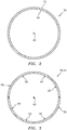
FIG. 2 is a cross-sectional illustration of a cold wall of the multi-walled structure. -
FIG. 3 is a cross-sectional illustration of a hot wall of the multi-walled structure. -
FIG. 4 is a plane view illustration of a panel of the hot wall. -
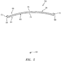
FIG. 5 is a cross-sectional illustration of the hot wall panel taken along line 5-5 inFIG. 4 . -
FIG. 6 is a side sectional illustration of the hot wall panel taken along line 6-6 inFIG. 4 . -
FIG. 7A is a side sectional illustration of a portion of the multi-walled structure shown in more detail with cold wall apertures and hot wall apertures. -
FIG. 7B is a side sectional illustration of a portion of the multi-walled structure with another arrangement of apertures. -
FIG. 7C is a side sectional illustration of a portion of the multi-walled structure with still another arrangement of apertures. -
FIG. 8 is a side sectional illustration of a portion of the multi-walled structure depicting cooling fluid flow through one of the cold wall apertures and one of the hot wall apertures. -
FIG. 9A is a perspective side sectional illustration of a portion of the hot wall configured with tortuous hot wall apertures. -
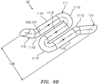
FIG. 9B is a perspective illustration depicting a tubular surface that forms an exemplary one of the tortuous hot wall apertures inFIG. 9A . -
FIG. 10 is a graph illustrating characteristics of a dual-walled structure with (a) straight-line effusions holes and (b) a higher cold panel pressure drop than hot panel pressure drop. -
FIG. 11 is a graph illustrating characteristics of the multi-walled structure ofFIG. 1 with (a) the hot wall apertures ofFIGS. 9A and9B and (b) a lower cold panel pressure drop than hot panel pressure drop. -
FIG. 12 is a side sectional illustration of a portion of the multi-walled structure configured with common trajectory cold and hot wall apertures. -
FIG. 13 is a side sectional illustration of a portion of the multi-walled structure configured with unique trajectory cold and hot wall apertures. -
FIGS 14A and 14B illustrate a portion of one of the hot wall apertures with a diffusion outlet portion. -
FIGS 15A and 15B illustrate a portion of one of the hot wall apertures with another diffusion outlet portion. -
FIGS 16A and 16B illustrate a portion of one of the hot wall apertures with another diffusion outlet portion. -
FIGS 17A and 17B illustrate a portion of one of the hot wall apertures with still another diffusion outlet portion. -
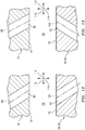
FIG. 18 is a sectional illustration of a portion of the cold wall and one of its apertures. -
FIG. 19 is a sectional illustration of a portion of the hot wall and one of its apertures. -
FIG. 20 is a partial side sectional illustration of another assembly with multiple multi-walled structures. -
FIG. 21 is a side cutaway illustration of a geared turbofan gas turbine engine. -
FIG. 1 illustrates anassembly 30 for a gas turbine engine. Thisturbine engine assembly 30 includes amulti-walled structure 32 such as, for example, a hollow dual-walled structure. For ease of description, themulti-walled structure 32 is described below as a wall of a combustor of the gas turbine engine. The present disclosure, however, is not limited to such an exemplary combustor application. For example, themulti-walled structure 32 may alternatively be configured as a duct wall, an airfoil wall, a vane wall, a case wall, a platform or any other multi-walled structure (e.g., wall structure with internal cooling) within the gas turbine engine. - The
multi-walled structure 32 ofFIG. 1 includes acold wall 34 and ahot wall 36. Themulti-walled structure 32 also includes one or moreinternal cooling cavities 38. - The term "cold wall" may describe herein a wall portion of the
multi-walled structure 32 that is subject to relatively low temperatures during operation of theturbine engine assembly 30. For example, where themulti-walled structure 32 is configured as part of a combustor, thecold wall 34 may be configured as an exterior wall (also sometimes referred to as a "shell") of a combustor wall. Alternatively, where themulti-walled structure 32 is configured as an airfoil or a vane, thecold wall 34 may be configured as an interior wall of an airfoil wall or a vane wall. - The
cold wall 34 ofFIG. 2 extends circumferentially about (e.g., completely around) anaxial centerline 40 of theturbine engine assembly 30; e.g., a rotational axis and/or centerline axis of the gas turbine engine. Thiscold wall 34 may be configured as a monolithic full hoop body. Alternatively, thecold wall 34 may be configured from one or more segments; e.g., a pair of arcuate halves. Referring toFIG. 1 , thecold wall 34 extends longitudinally (e.g., generally axially along the axial centerline 40) between and to a cold wall first (e.g., forward / upstream)end 42 and a cold wall second (e.g., aft / downstream) end 44. Thecold wall 34 has a vertical thickness that extends vertically (e.g., generally radially relative to the axial centerline 40) between and to a cold wallexterior side 46 and a cold wallinterior side 48. - The
cold wall 34 may be constructed from or otherwise include metal. This metal may include, but is not limited to, nickel (Ni), aluminum (Al), titanium (Ti), steel, etc. The present disclosure, however, is not limited to the foregoing exemplary cold wall materials, nor to metal cold walls. - The term "hot wall" describes herein a wall portion of the
multi-walled structure 32 that is subject to relatively high temperatures during operation of theturbine engine assembly 30. For example, where themulti-walled structure 32 is configured as part of a combustor, thehot wall 36 may be configured as an interior wall (also sometimes referred to as a "heat shield" or a "liner") of a combustor wall. Alternatively, where themulti-walled structure 32 is configured as an airfoil or a vane, thehot wall 36 may be configured as an exterior wall of an airfoil wall or a vane wall. - The
hot wall 36 ofFIG. 3 extends circumferentially about (e.g., completely around) theaxial centerline 40. Referring toFIG. 1 , thehot wall 36 extends longitudinally (e.g., generally axially along the axial centerline 40) between and to a hot wall first (e.g., forward / upstream)end 50 and a hot wall second (e.g., aft / downstream)end 52. - The
hot wall 36 ofFIG. 1 includes / is formed by one ormore arrays FIG. 3 , each hot wall panel array 54 includes one or more (e.g., arcuate)hot wall panels 56; e.g., hot wall segments. Thehot wall panels 56 in each respective array 54 are arranged circumferentially end-to-end so as to provide thehot wall 36 ofFIG. 3 with a full hoop segmented body. Thehot wall 36 and one, some or each of itshot wall panels 56 may be construct from metal and/or ceramic. The metal may include, but is not limited to, nickel (Ni), aluminum (Al), titanium (Ti), steel, etc. The ceramic may include, but is not limited to, ceramic matrix composite (CMC) material; e.g., SiC/SiC. The present disclosure, however, is not limited to the foregoing exemplary hot wall materials, nor to metal nor ceramic hot walls / panels. - Referring to
FIG. 4 , eachhot wall panel 56 extends laterally (e.g., generally circumferentially about the axial centerline 40) between and to opposing panel sides 58; see alsoFIG. 5 . Eachhot wall panel 56 extends longitudinally (e.g., generally axially along the axial centerline 40) between and to a panel first (e.g., forward / upstream)end 60 and a panel second (e.g., aft / downstream)end 62; see alsoFIG. 6 . Referring toFIGS. 5 and6 , eachhot wall panel 56 extends vertically (e.g., generally radially relative to the axial centerline 40) between and to a panel exterior side 64 (e.g., hot side) and a panel interior side 66 (e.g., cold side). - Each
hot wall panel 56 ofFIGS. 4-6 includes apanel base 68 and one or more panel rails. The panel rails ofFIGS. 4-6 include one or more lateral rails 70 (e.g., end rails) and one or more longitudinal rails 72 (e.g., side rails). - The
panel base 68 extends laterally between and to the opposing panel sides 58. Thepanel base 68 extends longitudinally between and to the panelfirst end 60 and the panelsecond end 62. Thepanel base 68 extends vertically from an exterior hot wall panel surface 74 (e.g., a hot side surface / hot wall exterior surface) on thepanel exterior side 64 to an interior hot wall panel surface 76 (e.g., a cold side surface / hot wall interior surface) towards the panelinterior side 66. Thepanel base 68 ofFIG. 5 is configured with a curved (e.g., arcuate, partially circular, etc.) sectional geometry when viewed, for example, in a plane perpendicular to theaxial centerline 40; e.g., the plane ofFIG. 5 . Thepanel base 68 ofFIG. 6 is configured with a straight, linear sectional geometry when viewed, for example, in a plane parallel with theaxial centerline 40; e.g., the plane ofFIG. 6 . The present disclosure, however, is not limited to such exemplary panel base sectional geometries. - The hot wall
exterior surface 74 ofFIG. 5 extends laterally between and to the opposing panel sides 58. The hot wallexterior surface 74 ofFIG. 6 extends longitudinally between and to the panelfirst end 60 and the panelsecond end 62. - The hot wall
interior surface 76 ofFIG. 4 extends laterally between and to the longitudinal rails 72. The hot wallinterior surface 76 extends longitudinally between and to the lateral rails 70. - The
rails FIG. 4 are configured to collectively form a perimeter rail (e.g., completely) around thehot wall panel 56 and its hot wallinterior surface 76. Eachlateral rail 70 ofFIG. 4 , for example, is located at (e.g., on, adjacent or proximate) arespective panel end lateral rail 70 extends laterally along thepanel base 68 between and is connected to the longitudinal rails 72. Eachlongitudinal rail 72 ofFIG. 4 is located at (e.g., on, adjacent or proximate) arespective panel side 58. Eachlongitudinal rail 72 extends longitudinally along thepanel base 68 between and is connected to the lateral rails 70. Each of therails panel base 68 and projects vertically out from thepanel base 68 to a distal end configured to sealingly engage (e.g., contact) aninterior surface 78 of thecold wall 34 as shown inFIG. 1 . - Each cooling
cavity 38 ofFIG. 1 is formed within themulti-walled structure 32 vertically between and by thecold wall 34 and thehot wall 36. In particular, each coolingcavity 38 extends vertically between and to the cold wallinterior surface 78 and a respective one of thehot wall panels 56 and its hot wallinterior surface 76. Each coolingcavity 38 ofFIG. 1 extends longitudinally between and to the lateral rails 70 of a respective one of thehot wall panels 56. Each coolingcavity 38 ofFIG. 4 extends laterally between and to thelongitudinal rails 72 of a respective one of thehot wall panels 56. - Referring to
FIG. 7 , each coolingcavity 38 is fluidly coupled with one or morerespective apertures 80 in thecold wall 34 and one or morerespective apertures 82 in thehot wall 36. The coolingcavity 38 thereby (e.g., directly) fluidly couples the respectivecold wall apertures 80 with the respectivehot wall apertures 82. - Referring to
FIG. 8 , one, some or each of thecold wall apertures 80 is configured as an impingement aperture. For example, eachcold wall aperture 80 ofFIG. 8 is configured to direct ajet 84 of cooling fluid (e.g., gas) through therespective cooling cavity 38 and against a respective one of thehot wall panels 56 and its hot wallinterior surface 76. - Under certain operating conditions, some cooling fluids (e.g., compressed air) may include foreign matter particles such as, but not limited to, sand and/or dirt. To prevent and/or reduce accumulation of foreign matter deposits on the hot wall
interior surface 76, one, some or each of thecold wall apertures 80 may be angled such that the coolingfluid jet 84 impinges against the hot wallinterior surface 76 at anon-ninety degree angle 86; e.g., an acute angle. With such an angled trajectory, foreign matter carried by a respectivecooling fluid jet 84 strikes the hot wallinterior surface 76 with a smaller vertical force. The foreign matter may thereby be less likely to stick to the hot wallinterior surface 76 upon impact. - Each
cold wall aperture 80 extends along a respective cold wall aperture centerline 88 (e.g., a centerline axis) through thecold wall 34 from anexterior surface 90 of thecold wall 34 to the cold wallinterior surface 78. The coldwall aperture centerline 88 may be a straight, linear centerline; however, the present disclosure is not limited thereto. The coldwall aperture centerline 88 ofFIG. 7A is angularly offset from one or more of thesurfaces angle centerline 88 of one, some or each of thecold wall apertures 80 may be arranged perpendicular to one or more of thesurfaces - One, some or each of the
hot wall apertures 82 is configured as an effusion aperture. For example, eachhot wall aperture 82 ofFIG. 8 is configured to direct a jet /flow 96 of cooling fluid (e.g., gas) out of themulti-walled structure 32 and into a plenum 98 (e.g., a combustion chamber) adjacent and/or formed partially by the hot wallexterior surface 74. Once within theplenum 98, the coolingfluid 96 exhausted from the respectivehot wall aperture 82 may be pushed against and/or towards the hot wallexterior surface 74 by fluid (e.g., combustion gases) within theplenum 98 and form a protective barrier (e.g., film) against / along a downstream portion of the hot wallexterior surface 74. - Each
hot wall aperture 82 extends along a respective hotwall aperture centerline 100 through thehot wall 36 from the respective hot wallinterior surface 76 to the respective hot wallexterior surface 74. The hotwall aperture centerline 100 may be a straight, linear centerline; however, the present disclosure is not limited thereto as described below in further detail. The hotwall aperture centerline 100 ofFIG. 7A is angularly offset from one or more of thesurfaces angle - As the cooling fluid flows sequentially through the
cold wall apertures 80, thecooling cavities 38 and thehot wall apertures 82, themulti-walled structure 32 is subject to a total pressure drop vertically thereacross. This total pressure drop may be measured / quantified by subtracting pressure of the cooling fluid exhausted form thehot wall apertures 82 from pressure of the cooling fluid flowing into thecold wall apertures 80; e.g., the pressure of the cooling fluid within aplenum 106 adjacent and/or formed partially by the cold wallexterior surface 90. Similarly, thecold wall 34 is subject to a cold wall pressure drop vertically thereacross and thehot wall 36 is subject to a hot wall pressure drop vertically thereacross. - The
multi-walled structure 32 may be configured such that hot wall pressure drop is greater than (or equal to) the cold wall pressure drop. For example, the hot wall pressure drop may be greater than at least one and one-quarter times (1.25x) the cold wall pressure drop. The hot wall pressure drop, for example, may be between one and one-half times (1.5x) and nine times (9x) the cold wall pressure drop. Mar particularly, the hot wall pressure drop may be between two times (2x) and four times (4x) the cold wall pressure drop. Such a configuration may enable the cooling fluid to travel faster through thehot wall apertures 82 than thecold wall apertures 80 and, for example, thereby increase convection within theapertures 82. Such a configuration may also or alternatively enable provision of more complexhot wall aperture 82 configurations as discussed below in further detail. - The cold wall pressure drop may be equal to or less than fifty percent (50%) of the total pressure drop vertically across the
multi-walled structure 32; e.g., equal to or less than forty-five percent (45%) of the total pressure drop vertically across themulti-walled structure 32. For example, the cold wall pressure drop may be equal to between five percent (5%) and forty-five percent (45%) of the total pressure drop vertically across themulti-walled structure 32. More particularly, the cold wall pressure drop may be equal to between ten percent (10%) and forty percent (40%) of the total pressure drop vertically across themulti-walled structure 32. Still more particularly, the cold wall pressure drop may be equal to between twenty percent (20%) and thirty percent (30%) of the total pressure drop vertically across themulti-walled structure 32. - The hot wall pressure drop may be equal to or greater than fifty percent (50%) of the total pressure drop vertically across the
multi-walled structure 32; e.g., equal to or greater than fifty-five percent (55%) of the total pressure drop vertically across themulti-walled structure 32. For example, the hot wall pressure drop may be equal to between fifty-five percent (55%) and ninety-five percent (95%) of the total pressure drop vertically across themulti-walled structure 32. More particularly, the hot wall pressure drop may be equal to between sixty percent (60%) and ninety percent (90%) of the total pressure drop vertically across themulti-walled structure 32. Still more particularly, the hot wall pressure drop may be equal to between seventy percent (70%) and eighty percent (80%) of the total pressure drop vertically across themulti-walled structure 32. The present disclosure, however, is not limited to the foregoing exemplary total, cold wall and/or hot wall pressure drops. - As discussed briefly above, configuring the
multi-walled structure 32 such that the hot wall pressure drop is greater than the cold wall pressure drop enables thehot wall 36 and one, some or each of itspanels 56 to be configured with relatively complexhot wall apertures 82. For example, referring toFIGS. 9A and9B , eachhot wall aperture 82 has a tortuous (e.g., non-linear, curved, compound, serpentine, etc.) configuration. More particular, the hotwall aperture centerline 100 ofFIGS. 9A and9B follows a tortuous trajectory through thehot wall 36 and itspanel 56. With such a tortuous configuration, a longitudinal length 107 (seeFIG. 9B ) of eachhot wall aperture 82 along itscenterline 100 between thesurfaces 74 and 76 (seeFIG. 9A ) may be greater than avertical thickness 108 of thehot wall 36 and itspanel 56 between thesurfaces vertical thickness 108. The longitudinal length 107, for example, may be between two times (2x) and twenty times (20x) thevertical thickness 108. Providing the respectivehot wall aperture 82 with its extended longitudinal length 107 (as compared to the vertical thickness 108) increases time the cooling fluid is within thehot wall 36 as well as increases surface area to which the cooling fluid is exposed. Thus, providing thehot wall apertures 82 with tortuous configurations may increase cooling of thehot wall 36. Hot wall cooling may thereby be less dependent upon impingement cooling (seeFIG. 8 ) and, thus, less impacted by accumulation of foreign matter on the hot wall interior surfaces 76. - Each
hot wall aperture 82 ofFIGS. 9A and9B includes aninlet segment 110, a serpentineintermediate segment 111 and anoutlet segment 112. Theinlet segment 110 extends into thehot wall 36 and itsrespective panel 56 from the respective hot wallinterior surface 76. Theinlet segment 110 ofFIG. 9B has a straight, linear configuration where thecenterline 100 along thisinlet segment 110 is angularly offset from theinterior surface 76 by an included angle (e.g., 104 inFIG. 7A ); e.g., an acute angle. Theintermediate segment 111 may generally lie in a plane that is substantially parallel to one or more of thesurfaces intermediate segment 111 includes one or more major (e.g., straight, linear)sections 111A-C and one or more connection (e.g., curved, elbow)sections 111D-111G which interconnect themajor sections 111A-C together and to theinlet segment 110 and theoutlet segment 112. Theoutlet segment 112 extends into thehot wall 36 and itsrespective panel 56 from the respective hot wallexterior surface 74. Theoutlet segment 112 ofFIG. 9B has a straight, linear configuration where thecenterline 100 along thisoutlet segment 112 is angularly offset from theexterior surface 74 by an included angle (e.g., 102 inFIG. 7A ); e.g., an acute angle. Furthermore, theoutlet segment 112 may extend to theexterior surface 74 in a common (e.g., lateral and/or longitudinal) direction as theinlet segment 110 extends from theinterior surface 76. The present disclosure is not limited, however, to such an exemplary tortuous hot wall aperture configuration. Another example of a suitable hot wall aperture configuration is disclosed inU.S. Publication No. 2016/0230993 , which is hereby incorporated herein by reference in its entirety. -
FIG. 10 is a graph illustrating characteristics of a dual-walled structure with (a) straight-line impingement and effusions holes and (b) a higher cold panel pressure drop than hot panel pressure drop.FIG. 11 is graph illustrating characteristics of themulti-walled structure 32 described above along with thehot wall aperture 82 configuration ofFIGS. 9A and9B . Notably, overall cooling effectiveness of thehot wall 36 is significantly higher inFIG. 11 than inFIG. 10 . As a result, the number of thehot wall apertures 82 in thehot wall 36 may also be reduced to reduce the hole density in thesurface 74. By reducing hole density in the hot wall exterior surfaces 74, a coating on that surface 74 (e.g., a thermal barrier coating) may be less susceptible to spallation. - In some embodiments, referring to
FIG. 12 , at least a portion (or an entirety of) a respective coldwall aperture centerline 88 that extends to the cold wallinterior surface 78 has a trajectory with a component in a first (e.g., longitudinal and/or lateral; left-to-right inFIG. 12 )direction 114 and another component in a vertical (e.g., downward inFIG. 12 )direction 116. Similarly, at least a portion (or an entirety of) a respective hotwall aperture centerline 100 that extends from the hot wallinterior surface 76 has a trajectory with a component in thefirst direction 114 and another component in thevertical direction 116. Thus, at least an outlet portion of the respectivecold wall aperture 80 extends in a similar or same direction as at least an inlet portion of the respectivehot wall aperture 82. The present disclosure, however, is not limited to such an exemplary embodiment. For example, in the embodiment ofFIG. 13 , the trajectory of the hotwall aperture centerline 100 may have a component in a second (e.g., longitudinal and/or lateral; right-to-left inFIG. 13 )direction 118 that is different than (e.g., opposite to, perpendicular to, angularly offset from, etc.) thefirst direction 114. - In some embodiments, referring to
FIGS. 14A-17B , one, some or each of thehot wall apertures 82 is configured with adiffusion outlet portion 120 at (e.g., on, adjacent or proximate) the respective hot wallexterior surface 74. Thisdiffusion outlet portion 120 is configured to diffuse the cooling fluid being exhausted from the respectivehot wall aperture 82. The present disclosure, of course, is not limited to the exemplary diffusion outlet portion configurations illustrated inFIGS. 14A-17B . - Referring to
FIG. 18 , eachcold wall aperture 80 has a cold wall aperture width 122 (e.g., diameter) measured in a plane perpendicular to its coldwall aperture centerline 88. Referring toFIG. 19 , eachhot wall aperture 82 has a hot wall aperture width 124 (e.g., diameter) measured in a plane perpendicular to its hotwall aperture centerline 100. The hot wall aperture width 124 (e.g., at the respective hot wall interior surface 76) may be equal to or different (e.g., greater or less) that the cold wall aperture width 122 (e.g., at the cold wall exterior surface 90). - Referring to
FIG. 7A , thecold wall 34 includes (e.g., only has) a first quantity of thecold wall apertures 80 fluidly coupled with arespective cooling cavity 38. Thehot wall 36 and arespective panel 56 includes (e.g., only has) a second quantity of thehot wall apertures 82 fluidly coupled with therespective cooling cavity 38. The second quantity may be equal to or different (e.g., greater or less) than the first quantity. - The
cold wall apertures 80 provide thecold wall 34 with a cold wall percentage of open area (POA) to a respective one of thecooling cavities 38. Thehot wall apertures 82 provide thehot wall 36 and itsrespective panel 56 with a hot wall percentage of open area (POA) to the respective one of thecooling cavities 38. The term "percentage of open area" may describe a percentage of a surface area of an element (e.g., thesurface 90, 76) that is occupied by open area (e.g., voids from theapertures 80, 82). The cold wall percentage of open area may be equal to or different (e.g., greater (seeFIG. 7B ) or less (seeFIG. 7C )) than the hot wall percentage of open area. By tailoring the percentages of open area, the relative quantities of theapertures apertures widths aperture apertures 80 per unit of area as shown, for example, inFIG. 7B ), theapertures 80 may protect thehot wall 36 where, for example, one or more of itsapertures 82 become clogged and/or a portion of thehot wall 36 is burnt during service. - While each
hot wall panel 56 is described above as being associated with a single one of thecooling cavities 38, the present disclosure is not limited to such an exemplary configuration. For example, in other embodiments, one, some or each of thehot wall panels 56 may also include at least one additional internal rail (e.g., seepanel 56A inFIG. 20 ) that subdivides a cooling cavity into multiple coolingcavities 38. Furthermore, while themulti-walled structure 32 is described above with itshot wall panels 56 as separately formed bodies from thecold wall 34, in other embodiments thehot wall 36 and thecold wall 34 may be formed together as a single monolithic body. -
FIG. 20 illustrates another assembly 126 for the gas turbine engine. This turbine engine assembly 126 includes acombustor 128 and one or more fuel injector assemblies 130 (one visible inFIG. 20 ). Briefly, eachfuel injector assembly 130 may include afuel injector 132 and aswirler 134 mated with thefuel injector 132. - The
combustor 128 includes aninner combustor wall 136, anouter combustor wall 138 and acombustor bulkhead 140. Thecombustor 128 may be configured as an annular combustor. Each of the inner andouter combustor walls axial centerline 40. Thecombustor bulkhead 140 may be an annular wall that extends circumferentially around theaxial centerline 40 and radially from theinner combustor wall 136 to theouter combustor wall 138. One, some or each of thecombustor components multi-walled structure 32 configuration described above. -
FIG. 21 is a side cutaway illustration of a gearedturbine engine 142 with which theturbine engine assembly 30 ofFIG. 1 and/or the turbine engine assembly 126 ofFIG. 20 may be configured. Theturbine engine 142 extends along an axial centerline (e.g., the axial centerline 40) between anupstream airflow inlet 144 and adownstream airflow exhaust 146. Theturbine engine 142 includes afan section 148, acompressor section 149, acombustor section 150 and aturbine section 151. Thecompressor section 149 includes a low pressure compressor (LPC)section 149A and a high pressure compressor (HPC)section 149B. Theturbine section 151 includes a high pressure turbine (HPT)section 151A and a low pressure turbine (LPT)section 151B. - The engine sections 148-151B are arranged sequentially along the
axial centerline 40 within anengine housing 154. Thisengine housing 154 includes an inner case 156 (e.g., a core case) and an outer case 158 (e.g., a fan case). Theinner case 156 may house one or more of theengine sections 149A-151B; e.g., an engine core. Theouter case 158 may house at least thefan section 148. - Each of the
engine sections - The
fan rotor 160 is connected to agear train 166, for example, through afan shaft 168. Thegear train 166 and theLPC rotor 161 are connected to and driven by theLPT rotor 164 through alow speed shaft 169. TheHPC rotor 162 is connected to and driven by theHPT rotor 163 through ahigh speed shaft 170. The shafts 168-170 are rotatably supported by a plurality ofbearings 172; e.g., rolling element and/or thrust bearings. Each of thesebearings 172 is connected to theengine housing 154 by at least one stationary structure such as, for example, an annular support strut. - During operation, air enters the
turbine engine 142 through theairflow inlet 144. This air is directed through thefan section 148 and into acore gas path 174 and abypass gas path 176. Thecore gas path 174 extends sequentially through theengine sections 149A-151B. The air within thecore gas path 174 may be referred to as "core air". Thebypass gas path 176 extends through a bypass duct, which bypasses the engine core. The air within thebypass gas path 176 may be referred to as "bypass air". - The core air is compressed by the
compressor rotors combustion chamber 98 of thecombustor 128 in thecombustor section 150. Fuel is injected into thecombustion chamber 98 and mixed with the compressed core air to provide a fuel-air mixture. This fuel air mixture is ignited and combustion products thereof flow through and sequentially cause theturbine rotors turbine rotors compressor rotors turbine rotor 164 also drives rotation of thefan rotor 160, which propels bypass air through and out of thebypass gas path 176. The propulsion of the bypass air may account for a majority of thrust generated by theturbine engine 142, e.g., more than seventy-five percent (75%) of engine thrust. Theturbine engine 142 of the present disclosure, however, is not limited to the foregoing exemplary thrust ratio. - The
turbine engine assembly 30, 126 may be included in various turbine engines other than the one described above. Theturbine engine assembly 30, 126, for example, may be included in a geared turbine engine where a gear train connects one or more shafts to one or more rotors in a fan section, a compressor section and/or any other engine section. Alternatively, theturbine engine assembly 30, 126 may be included in a turbine engine configured without a gear train. Theturbine engine assembly 30, 126 may be included in a geared or non-geared turbine engine configured with a single spool, with two spools (e.g., seeFIG. 21 ), or with more than two spools. The turbine engine may be configured as a turbofan engine, a turbojet engine, a propfan engine, a pusher fan engine or any other type of turbine engine. The present disclosure therefore is not limited to any particular types or configurations of turbine engines. - While various embodiments of the present disclosure have been described, it will be apparent to those of ordinary skill in the art that many more embodiments and implementations are possible within the scope of the disclosure. For example, the present disclosure as described herein includes several aspects and embodiments that include particular features. Although these features may be described individually, it is within the scope of the present disclosure that some or all of these features may be combined with any one of the aspects and remain within the scope of the disclosure. Accordingly, the present disclosure is not to be restricted except in light of the attached claims and their equivalents.
Claims (15)
- An assembly (30) for a gas turbine engine, comprising:a multi-walled structure (32) including a cold wall (34), a hot wall (36) and a cooling cavity (38) vertically between the cold wall (34) and the hot wall (36);the cold wall (34) comprising a plurality of cold wall apertures (80) fluidly coupled with the cooling cavity (38), and the plurality of cold wall apertures (80) configured to subject the cold wall (34) to a cold wall pressure drop vertically across the cold wall (34); andthe hot wall (36) comprising a plurality of hot wall apertures (82) fluidly coupled with the cooling cavity (38), and the plurality of hot wall apertures (82) configured to subject the hot wall (36) to a hot wall pressure drop vertically across the hot wall (36) that is greater than or equal to the cold wall pressure drop.
- The assembly (30) of claim 1, wherein the multi-walled structure (32) is configured such that the cold wall pressure drop is equal to between five percent and forty-five percent of a total pressure drop vertically across the multi-walled structure (32).
- The assembly (30) of claim 1 or 2, wherein the multi-walled structure (32) is configured such that the hot wall pressure drop is equal to between fifty-five percent and ninety five percent of a total pressure drop vertically across the multi-walled structure (32), and wherein the hot wall pressure drop is optionally at least one and one-quarter times the cold wall pressure drop.
- The assembly (30) of claim 1, 2, or 3, wherein the plurality of cold wall apertures (80) comprise an impingement aperture configured to direct a jet (84) of cooling fluid to impinge against the hot wall (36).
- The assembly (30) of any preceding claim, wherein:the plurality of cold wall apertures (80) comprise a first cold wall aperture that extends through the cold wall (34) along a cold wall aperture centerline (88); andthe cold wall aperture centerline (88) is angularly offset from an interior surface (78) of the cold wall (34) by an acute angle (92).
- The assembly (30) of any preceding claim, wherein the plurality of hot wall apertures (82) comprise:an effusion aperture configured to direct cooling fluid out of the cooling cavity (38) into a plenum (98) and along an exterior surface (74) of the hot wall (36); and/ora first hot wall aperture with a diffusion outlet portion (120).
- The assembly (30) of any preceding claim, wherein the plurality of hot wall apertures (82) comprise a or the first hot wall aperture that extends through the hot wall (36) along a hot wall aperture centerline (100) with a tortuous trajectory, and wherein a longitudinal length (107) of the first hot wall aperture along the hot wall aperture centerline (100) is optionally greater than a thickness (108) of the hot wall (36).
- The assembly (30) of any preceding claim, wherein:the plurality of cold wall apertures (80) comprise a or the first cold wall aperture that extends through the cold wall (34) along a cold wall aperture centerline (88), and at least a portion of the cold wall aperture centerline (88) that extends to an interior surface (78) of the cold wall (34) defining the cooling cavity (38) has a trajectory with a component in a first direction (114) and a component in a vertical direction (116); andthe plurality of hot wall apertures (82) comprise a or the first hot wall aperture that extends through the hot wall (36) along a hot wall aperture centerline (100), and at least a portion of the hot wall aperture centerline (100) that extends from an interior surface (76) of the hot wall (36) defining the cooling cavity (38) has a trajectory with a component in the vertical direction (116) and a component in either the first direction (114) or in a second direction (118) different from the first direction (114).
- The assembly (30) of any preceding claim, wherein:the plurality of cold wall apertures (80) comprise a or the first cold wall aperture with a first diameter (122); andthe plurality of hot wall apertures (82) comprise a or the first hot wall aperture with a second diameter (124) that is less than the first diameter (122).
- The assembly (30) of any preceding claim, wherein:the plurality of cold wall apertures (80) consist of a first quantity of cold wall apertures (80); andthe plurality of hot wall apertures (82) consist of a second quantity of hot wall apertures (82) that is less than the first quantity of cold wall apertures (80).
- The assembly (30) of any preceding claim, wherein:the cold wall (34) is configured with a first percentage of open area to the cooling cavity (38); andthe hot wall (36) is configured with a second percentage of open area from the cooling cavity (38) that is less than the first percentage of open area.
- The assembly (30) of any preceding claim, further comprising a combustor (128) of the gas turbine engine, the combustor (128) comprising the multi-walled structure (32).
- An assembly (30) for a gas turbine engine, comprising:a multi-walled structure (32) including a cold wall (34), a hot wall (36) and a cooling cavity (38) between the cold wall (34) and the hot wall (36);the cold wall (34) comprising a plurality of cold wall apertures (80) fluidly coupled with the cooling cavity (38), and the plurality of cold wall apertures (80) providing the cold wall (34) with a first percentage of open area;the hot wall (36) comprising a plurality of hot wall apertures (82) fluidly coupled with the cooling cavity (38), and the plurality of hot wall apertures (82) providing the hot wall (36) with a second percentage of open area that is less than the first percentage of open area.
- An assembly (30) for a gas turbine engine, comprising:a multi-walled structure (32) including a cold wall (34), a hot wall (36) and a cooling cavity (38) between and formed by the cold wall (34) and the hot wall (36);the cold wall (34) comprising a plurality of cold wall apertures (80) fluidly coupled with the cooling cavity (38), the plurality of cold wall apertures (80) comprising a first cold wall aperture that extends through the cold wall (34) along a cold wall aperture centerline (88) that is angularly offset from an interior surface (78) of the cold wall (34) by an acute angle (92); andthe hot wall (36) comprising a plurality of hot wall apertures (100) fluidly coupled with the cooling cavity (38), and the plurality of hot wall apertures (82) comprising a first hot wall aperture that extends through the hot wall (36) along a hot wall aperture centerline (100) with a tortuous trajectory,wherein a longitudinal length (107) of the first hot wall aperture along the hot wall aperture centerline (100) is optionally greater than a thickness (108) of the hot wall (36) and less than or equal to twenty times the thickness (108) of the hot wall (36).
- The assembly (30) of claim 14, wherein
at least a portion of the cold wall aperture centerline (88) that extends to an interior surface (78) of the cold wall (34) defining the cooling cavity (38) has a cold wall aperture centerline trajectory with a component in a first direction (114) and a component in a second direction (116); and
at least a portion of the hot wall aperture centerline (100) that extends from an interior surface (76) of the hot wall (36) defining the cooling cavity (38) has a hot wall aperture centerline trajectory with a component in the first direction (114) and a component in the second direction (116).
Applications Claiming Priority (1)
| Application Number | Priority Date | Filing Date | Title |
|---|---|---|---|
| US16/883,266 US11486578B2 (en) | 2020-05-26 | 2020-05-26 | Multi-walled structure for a gas turbine engine |
Publications (2)
| Publication Number | Publication Date |
|---|---|
| EP3916303A1 true EP3916303A1 (en) | 2021-12-01 |
| EP3916303B1 EP3916303B1 (en) | 2023-06-28 |
Family
ID=76098833
Family Applications (1)
| Application Number | Title | Priority Date | Filing Date |
|---|---|---|---|
| EP21175625.9A Active EP3916303B1 (en) | 2020-05-26 | 2021-05-25 | Assembly for a gas turbine engine comprising a combustor with a multi-walled structure |
Country Status (2)
| Country | Link |
|---|---|
| US (1) | US11486578B2 (en) |
| EP (1) | EP3916303B1 (en) |
Cited By (1)
| Publication number | Priority date | Publication date | Assignee | Title |
|---|---|---|---|---|
| CN114991991A (en) * | 2022-05-30 | 2022-09-02 | 中国航发四川燃气涡轮研究院 | Stress application vibration-proof heat screen with cold air adjusting function |
Families Citing this family (1)
| Publication number | Priority date | Publication date | Assignee | Title |
|---|---|---|---|---|
| CN117109030B (en) | 2022-05-16 | 2025-09-19 | 通用电气公司 | Thermal acoustic damper in combustor liner |
Citations (6)
| Publication number | Priority date | Publication date | Assignee | Title |
|---|---|---|---|---|
| US6470685B2 (en) * | 2000-04-14 | 2002-10-29 | Rolls-Royce Plc | Combustion apparatus |
| US20070245742A1 (en) * | 2004-10-25 | 2007-10-25 | Stefan Dahlke | Method of Optimum Controlled Outlet, Impingement Cooling and Sealing of a Heat Shield and a Heat Shield Element |
| US20140096528A1 (en) * | 2012-10-04 | 2014-04-10 | United Technologies Corporation | Cooling for Combustor Liners with Accelerating Channels |
| US20160230993A1 (en) | 2015-02-10 | 2016-08-11 | United Technologies Corporation | Combustor liner effusion cooling holes |
| US20160356500A1 (en) * | 2013-09-16 | 2016-12-08 | United Technologies Corporation | Controlled variation of pressure drop through effusion cooling in a double walled combustor of a gas turbine engine |
| US20190277501A1 (en) * | 2018-03-07 | 2019-09-12 | United Technologies Corporation | Slot arrangements for an impingement floatwall film cooling of a turbine engine |
Family Cites Families (24)
| Publication number | Priority date | Publication date | Assignee | Title |
|---|---|---|---|---|
| US6247896B1 (en) | 1999-06-23 | 2001-06-19 | United Technologies Corporation | Method and apparatus for cooling an airfoil |
| US6627019B2 (en) | 2000-12-18 | 2003-09-30 | David C. Jarmon | Process for making ceramic matrix composite parts with cooling channels |
| US7464554B2 (en) | 2004-09-09 | 2008-12-16 | United Technologies Corporation | Gas turbine combustor heat shield panel or exhaust panel including a cooling device |
| US7658590B1 (en) | 2005-09-30 | 2010-02-09 | Florida Turbine Technologies, Inc. | Turbine airfoil with micro-tubes embedded with a TBC |
| US7789626B1 (en) | 2007-05-31 | 2010-09-07 | Florida Turbine Technologies, Inc. | Turbine blade with showerhead film cooling holes |
| US8092176B2 (en) | 2008-09-16 | 2012-01-10 | Siemens Energy, Inc. | Turbine airfoil cooling system with curved diffusion film cooling hole |
| US8307657B2 (en) | 2009-03-10 | 2012-11-13 | General Electric Company | Combustor liner cooling system |
| US8052378B2 (en) | 2009-03-18 | 2011-11-08 | General Electric Company | Film-cooling augmentation device and turbine airfoil incorporating the same |
| US20100272953A1 (en) | 2009-04-28 | 2010-10-28 | Honeywell International Inc. | Cooled hybrid structure for gas turbine engine and method for the fabrication thereof |
| US9097117B2 (en) | 2010-11-15 | 2015-08-04 | Siemens Energy, Inc | Turbine transition component formed from an air-cooled multi-layer outer panel for use in a gas turbine engine |
| US8667682B2 (en) | 2011-04-27 | 2014-03-11 | Siemens Energy, Inc. | Method of fabricating a nearwall nozzle impingement cooled component for an internal combustion engine |
| CH706090A1 (en) | 2012-02-17 | 2013-08-30 | Alstom Technology Ltd | A method for manufacturing a near-surface cooling passage in a thermally highly stressed component and component with such a channel. |
| US9267690B2 (en) | 2012-05-29 | 2016-02-23 | General Electric Company | Turbomachine combustor nozzle including a monolithic nozzle component and method of forming the same |
| EP2712699A1 (en) * | 2012-10-01 | 2014-04-02 | Siemens Aktiengesellschaft | Method for protecting a component, method for laser boring and component |
| US9765968B2 (en) * | 2013-01-23 | 2017-09-19 | Honeywell International Inc. | Combustors with complex shaped effusion holes |
| US9309809B2 (en) | 2013-01-23 | 2016-04-12 | General Electric Company | Effusion plate using additive manufacturing methods |
| DE102013003444A1 (en) | 2013-02-26 | 2014-09-11 | Rolls-Royce Deutschland Ltd & Co Kg | Impact-cooled shingle of a gas turbine combustor with extended effusion holes |
| WO2014143209A1 (en) | 2013-03-15 | 2014-09-18 | Rolls-Royce Corporation | Gas turbine engine combustor liner |
| DE102013214487A1 (en) * | 2013-07-24 | 2015-01-29 | Rolls-Royce Deutschland Ltd & Co Kg | Combustor shingle of a gas turbine |
| US9410702B2 (en) | 2014-02-10 | 2016-08-09 | Honeywell International Inc. | Gas turbine engine combustors with effusion and impingement cooling and methods for manufacturing the same using additive manufacturing techniques |
| GB201417587D0 (en) | 2014-10-06 | 2014-11-19 | Rolls Royce Plc | A cooked component |
| GB201419327D0 (en) | 2014-10-30 | 2014-12-17 | Rolls Royce Plc | A cooled component |
| GB201521077D0 (en) | 2015-11-30 | 2016-01-13 | Rolls Royce | A cooled component |
| US10544683B2 (en) * | 2016-08-30 | 2020-01-28 | Rolls-Royce Corporation | Air-film cooled component for a gas turbine engine |
-
2020
- 2020-05-26 US US16/883,266 patent/US11486578B2/en active Active
-
2021
- 2021-05-25 EP EP21175625.9A patent/EP3916303B1/en active Active
Patent Citations (6)
| Publication number | Priority date | Publication date | Assignee | Title |
|---|---|---|---|---|
| US6470685B2 (en) * | 2000-04-14 | 2002-10-29 | Rolls-Royce Plc | Combustion apparatus |
| US20070245742A1 (en) * | 2004-10-25 | 2007-10-25 | Stefan Dahlke | Method of Optimum Controlled Outlet, Impingement Cooling and Sealing of a Heat Shield and a Heat Shield Element |
| US20140096528A1 (en) * | 2012-10-04 | 2014-04-10 | United Technologies Corporation | Cooling for Combustor Liners with Accelerating Channels |
| US20160356500A1 (en) * | 2013-09-16 | 2016-12-08 | United Technologies Corporation | Controlled variation of pressure drop through effusion cooling in a double walled combustor of a gas turbine engine |
| US20160230993A1 (en) | 2015-02-10 | 2016-08-11 | United Technologies Corporation | Combustor liner effusion cooling holes |
| US20190277501A1 (en) * | 2018-03-07 | 2019-09-12 | United Technologies Corporation | Slot arrangements for an impingement floatwall film cooling of a turbine engine |
Cited By (2)
| Publication number | Priority date | Publication date | Assignee | Title |
|---|---|---|---|---|
| CN114991991A (en) * | 2022-05-30 | 2022-09-02 | 中国航发四川燃气涡轮研究院 | Stress application vibration-proof heat screen with cold air adjusting function |
| CN114991991B (en) * | 2022-05-30 | 2024-04-02 | 中国航发四川燃气涡轮研究院 | Stress application vibration-proof heat shield with cold air adjustable function |
Also Published As
| Publication number | Publication date |
|---|---|
| EP3916303B1 (en) | 2023-06-28 |
| US11486578B2 (en) | 2022-11-01 |
| US20210372620A1 (en) | 2021-12-02 |
Similar Documents
| Publication | Publication Date | Title |
|---|---|---|
| EP3366995B1 (en) | Combustor liner panel assembly and method for cooling the same | |
| US10677462B2 (en) | Combustor liner panel end rail angled cooling interface passage for a gas turbine engine combustor | |
| US10753608B2 (en) | Turbine engine multi-walled structure with internal cooling element(s) | |
| EP3366997B1 (en) | Combustor liner panel end rail cooling enhancement features for a gas turbine engine combustor | |
| US20170009987A1 (en) | Stepped heat shield for a turbine engine combustor | |
| US10830448B2 (en) | Combustor liner panel with a multiple of heat transfer augmentors for a gas turbine engine combustor | |
| US20160201909A1 (en) | Gas turbine engine wall assembly with support shell contour regions | |
| US11499443B2 (en) | Ceramic wall seal interface cooling | |
| EP3916303B1 (en) | Assembly for a gas turbine engine comprising a combustor with a multi-walled structure | |
| US20160290644A1 (en) | Combustor quench aperture cooling | |
| EP3315730B1 (en) | Combustor seal and method for a gas turbine engine combustor | |
| EP3916304B1 (en) | Multi-walled structure for a gas turbine engine | |
| EP3321587B1 (en) | Axial non-linear interface for combustor liner panels in a gas turbine combustor | |
| EP3754260B1 (en) | Combustor comprising panels with skewed side walls | |
| EP3859212B1 (en) | Combustor shell with shaped impingement holes | |
| US11274559B2 (en) | Turbine blade tip dirt removal feature | |
| EP3321584B1 (en) | Gas turbine engine combustor with an axially non-planar combustor liner panel | |
| US12259133B2 (en) | Cooling combustor wall boss | |
| EP4328488B1 (en) | Gas turbine combustor with liner panel having a radiused gate | |
| EP3321585A1 (en) | Non-planar combustor liner panel for a gas turbine engine combustor | |
| US11280201B2 (en) | Baffle with tail | |
| US11149692B2 (en) | Deflection mitigation structure for combustion system | |
| EP3315862B1 (en) | Cast combustor liner panel with a radius edge for gas turbine engine combustor | |
| US10823414B2 (en) | Hooded entrance to effusion holes | |
| EP3321588B1 (en) | Combustor for a gas turbine engine |
Legal Events
| Date | Code | Title | Description |
|---|---|---|---|
| PUAI | Public reference made under article 153(3) epc to a published international application that has entered the european phase |
Free format text: ORIGINAL CODE: 0009012 |
|
| STAA | Information on the status of an ep patent application or granted ep patent |
Free format text: STATUS: THE APPLICATION HAS BEEN PUBLISHED |
|
| AK | Designated contracting states |
Kind code of ref document: A1 Designated state(s): AL AT BE BG CH CY CZ DE DK EE ES FI FR GB GR HR HU IE IS IT LI LT LU LV MC MK MT NL NO PL PT RO RS SE SI SK SM TR |
|
| B565 | Issuance of search results under rule 164(2) epc |
Effective date: 20210916 |
|
| STAA | Information on the status of an ep patent application or granted ep patent |
Free format text: STATUS: REQUEST FOR EXAMINATION WAS MADE |
|
| 17P | Request for examination filed |
Effective date: 20220601 |
|
| RBV | Designated contracting states (corrected) |
Designated state(s): AL AT BE BG CH CY CZ DE DK EE ES FI FR GB GR HR HU IE IS IT LI LT LU LV MC MK MT NL NO PL PT RO RS SE SI SK SM TR |
|
| GRAP | Despatch of communication of intention to grant a patent |
Free format text: ORIGINAL CODE: EPIDOSNIGR1 |
|
| STAA | Information on the status of an ep patent application or granted ep patent |
Free format text: STATUS: GRANT OF PATENT IS INTENDED |
|
| INTG | Intention to grant announced |
Effective date: 20230112 |
|
| GRAS | Grant fee paid |
Free format text: ORIGINAL CODE: EPIDOSNIGR3 |
|
| GRAA | (expected) grant |
Free format text: ORIGINAL CODE: 0009210 |
|
| STAA | Information on the status of an ep patent application or granted ep patent |
Free format text: STATUS: THE PATENT HAS BEEN GRANTED |
|
| AK | Designated contracting states |
Kind code of ref document: B1 Designated state(s): AL AT BE BG CH CY CZ DE DK EE ES FI FR GB GR HR HU IE IS IT LI LT LU LV MC MK MT NL NO PL PT RO RS SE SI SK SM TR |
|
| REG | Reference to a national code |
Ref country code: CH Ref legal event code: EP |
|
| REG | Reference to a national code |
Ref country code: AT Ref legal event code: REF Ref document number: 1582983 Country of ref document: AT Kind code of ref document: T Effective date: 20230715 |
|
| REG | Reference to a national code |
Ref country code: IE Ref legal event code: FG4D |
|
| REG | Reference to a national code |
Ref country code: DE Ref legal event code: R096 Ref document number: 602021003107 Country of ref document: DE |
|
| REG | Reference to a national code |
Ref country code: LT Ref legal event code: MG9D |
|
| PG25 | Lapsed in a contracting state [announced via postgrant information from national office to epo] |
Ref country code: SE Free format text: LAPSE BECAUSE OF FAILURE TO SUBMIT A TRANSLATION OF THE DESCRIPTION OR TO PAY THE FEE WITHIN THE PRESCRIBED TIME-LIMIT Effective date: 20230628 Ref country code: NO Free format text: LAPSE BECAUSE OF FAILURE TO SUBMIT A TRANSLATION OF THE DESCRIPTION OR TO PAY THE FEE WITHIN THE PRESCRIBED TIME-LIMIT Effective date: 20230928 |
|
| RAP4 | Party data changed (patent owner data changed or rights of a patent transferred) |
Owner name: RTX CORPORATION |
|
| REG | Reference to a national code |
Ref country code: NL Ref legal event code: MP Effective date: 20230628 |
|
| REG | Reference to a national code |
Ref country code: AT Ref legal event code: MK05 Ref document number: 1582983 Country of ref document: AT Kind code of ref document: T Effective date: 20230628 |
|
| PG25 | Lapsed in a contracting state [announced via postgrant information from national office to epo] |
Ref country code: RS Free format text: LAPSE BECAUSE OF FAILURE TO SUBMIT A TRANSLATION OF THE DESCRIPTION OR TO PAY THE FEE WITHIN THE PRESCRIBED TIME-LIMIT Effective date: 20230628 Ref country code: NL Free format text: LAPSE BECAUSE OF FAILURE TO SUBMIT A TRANSLATION OF THE DESCRIPTION OR TO PAY THE FEE WITHIN THE PRESCRIBED TIME-LIMIT Effective date: 20230628 Ref country code: LV Free format text: LAPSE BECAUSE OF FAILURE TO SUBMIT A TRANSLATION OF THE DESCRIPTION OR TO PAY THE FEE WITHIN THE PRESCRIBED TIME-LIMIT Effective date: 20230628 Ref country code: LT Free format text: LAPSE BECAUSE OF FAILURE TO SUBMIT A TRANSLATION OF THE DESCRIPTION OR TO PAY THE FEE WITHIN THE PRESCRIBED TIME-LIMIT Effective date: 20230628 Ref country code: HR Free format text: LAPSE BECAUSE OF FAILURE TO SUBMIT A TRANSLATION OF THE DESCRIPTION OR TO PAY THE FEE WITHIN THE PRESCRIBED TIME-LIMIT Effective date: 20230628 Ref country code: GR Free format text: LAPSE BECAUSE OF FAILURE TO SUBMIT A TRANSLATION OF THE DESCRIPTION OR TO PAY THE FEE WITHIN THE PRESCRIBED TIME-LIMIT Effective date: 20230929 |
|
| PG25 | Lapsed in a contracting state [announced via postgrant information from national office to epo] |
Ref country code: FI Free format text: LAPSE BECAUSE OF FAILURE TO SUBMIT A TRANSLATION OF THE DESCRIPTION OR TO PAY THE FEE WITHIN THE PRESCRIBED TIME-LIMIT Effective date: 20230628 |
|
| PG25 | Lapsed in a contracting state [announced via postgrant information from national office to epo] |
Ref country code: SK Free format text: LAPSE BECAUSE OF FAILURE TO SUBMIT A TRANSLATION OF THE DESCRIPTION OR TO PAY THE FEE WITHIN THE PRESCRIBED TIME-LIMIT Effective date: 20230628 |
|
| PG25 | Lapsed in a contracting state [announced via postgrant information from national office to epo] |
Ref country code: ES Free format text: LAPSE BECAUSE OF FAILURE TO SUBMIT A TRANSLATION OF THE DESCRIPTION OR TO PAY THE FEE WITHIN THE PRESCRIBED TIME-LIMIT Effective date: 20230628 |
|
| PG25 | Lapsed in a contracting state [announced via postgrant information from national office to epo] |
Ref country code: IS Free format text: LAPSE BECAUSE OF FAILURE TO SUBMIT A TRANSLATION OF THE DESCRIPTION OR TO PAY THE FEE WITHIN THE PRESCRIBED TIME-LIMIT Effective date: 20231028 |
|
| PG25 | Lapsed in a contracting state [announced via postgrant information from national office to epo] |
Ref country code: SM Free format text: LAPSE BECAUSE OF FAILURE TO SUBMIT A TRANSLATION OF THE DESCRIPTION OR TO PAY THE FEE WITHIN THE PRESCRIBED TIME-LIMIT Effective date: 20230628 Ref country code: SK Free format text: LAPSE BECAUSE OF FAILURE TO SUBMIT A TRANSLATION OF THE DESCRIPTION OR TO PAY THE FEE WITHIN THE PRESCRIBED TIME-LIMIT Effective date: 20230628 Ref country code: RO Free format text: LAPSE BECAUSE OF FAILURE TO SUBMIT A TRANSLATION OF THE DESCRIPTION OR TO PAY THE FEE WITHIN THE PRESCRIBED TIME-LIMIT Effective date: 20230628 Ref country code: PT Free format text: LAPSE BECAUSE OF FAILURE TO SUBMIT A TRANSLATION OF THE DESCRIPTION OR TO PAY THE FEE WITHIN THE PRESCRIBED TIME-LIMIT Effective date: 20231030 Ref country code: IS Free format text: LAPSE BECAUSE OF FAILURE TO SUBMIT A TRANSLATION OF THE DESCRIPTION OR TO PAY THE FEE WITHIN THE PRESCRIBED TIME-LIMIT Effective date: 20231028 Ref country code: ES Free format text: LAPSE BECAUSE OF FAILURE TO SUBMIT A TRANSLATION OF THE DESCRIPTION OR TO PAY THE FEE WITHIN THE PRESCRIBED TIME-LIMIT Effective date: 20230628 Ref country code: EE Free format text: LAPSE BECAUSE OF FAILURE TO SUBMIT A TRANSLATION OF THE DESCRIPTION OR TO PAY THE FEE WITHIN THE PRESCRIBED TIME-LIMIT Effective date: 20230628 Ref country code: CZ Free format text: LAPSE BECAUSE OF FAILURE TO SUBMIT A TRANSLATION OF THE DESCRIPTION OR TO PAY THE FEE WITHIN THE PRESCRIBED TIME-LIMIT Effective date: 20230628 Ref country code: AT Free format text: LAPSE BECAUSE OF FAILURE TO SUBMIT A TRANSLATION OF THE DESCRIPTION OR TO PAY THE FEE WITHIN THE PRESCRIBED TIME-LIMIT Effective date: 20230628 |
|
| PG25 | Lapsed in a contracting state [announced via postgrant information from national office to epo] |
Ref country code: PL Free format text: LAPSE BECAUSE OF FAILURE TO SUBMIT A TRANSLATION OF THE DESCRIPTION OR TO PAY THE FEE WITHIN THE PRESCRIBED TIME-LIMIT Effective date: 20230628 |
|
| REG | Reference to a national code |
Ref country code: DE Ref legal event code: R097 Ref document number: 602021003107 Country of ref document: DE |
|
| PG25 | Lapsed in a contracting state [announced via postgrant information from national office to epo] |
Ref country code: DK Free format text: LAPSE BECAUSE OF FAILURE TO SUBMIT A TRANSLATION OF THE DESCRIPTION OR TO PAY THE FEE WITHIN THE PRESCRIBED TIME-LIMIT Effective date: 20230628 |
|
| PLBE | No opposition filed within time limit |
Free format text: ORIGINAL CODE: 0009261 |
|
| STAA | Information on the status of an ep patent application or granted ep patent |
Free format text: STATUS: NO OPPOSITION FILED WITHIN TIME LIMIT |
|
| PG25 | Lapsed in a contracting state [announced via postgrant information from national office to epo] |
Ref country code: IT Free format text: LAPSE BECAUSE OF FAILURE TO SUBMIT A TRANSLATION OF THE DESCRIPTION OR TO PAY THE FEE WITHIN THE PRESCRIBED TIME-LIMIT Effective date: 20230628 |
|
| 26N | No opposition filed |
Effective date: 20240402 |
|
| PG25 | Lapsed in a contracting state [announced via postgrant information from national office to epo] |
Ref country code: SI Free format text: LAPSE BECAUSE OF FAILURE TO SUBMIT A TRANSLATION OF THE DESCRIPTION OR TO PAY THE FEE WITHIN THE PRESCRIBED TIME-LIMIT Effective date: 20230628 |
|
| PG25 | Lapsed in a contracting state [announced via postgrant information from national office to epo] |
Ref country code: BG Free format text: LAPSE BECAUSE OF FAILURE TO SUBMIT A TRANSLATION OF THE DESCRIPTION OR TO PAY THE FEE WITHIN THE PRESCRIBED TIME-LIMIT Effective date: 20230628 |
|
| PG25 | Lapsed in a contracting state [announced via postgrant information from national office to epo] |
Ref country code: BG Free format text: LAPSE BECAUSE OF FAILURE TO SUBMIT A TRANSLATION OF THE DESCRIPTION OR TO PAY THE FEE WITHIN THE PRESCRIBED TIME-LIMIT Effective date: 20230628 |
|
| REG | Reference to a national code |
Ref country code: CH Ref legal event code: PL |
|
| PG25 | Lapsed in a contracting state [announced via postgrant information from national office to epo] |
Ref country code: MC Free format text: LAPSE BECAUSE OF FAILURE TO SUBMIT A TRANSLATION OF THE DESCRIPTION OR TO PAY THE FEE WITHIN THE PRESCRIBED TIME-LIMIT Effective date: 20230628 |
|
| PG25 | Lapsed in a contracting state [announced via postgrant information from national office to epo] |
Ref country code: LU Free format text: LAPSE BECAUSE OF NON-PAYMENT OF DUE FEES Effective date: 20240525 |
|
| PG25 | Lapsed in a contracting state [announced via postgrant information from national office to epo] |
Ref country code: MC Free format text: LAPSE BECAUSE OF FAILURE TO SUBMIT A TRANSLATION OF THE DESCRIPTION OR TO PAY THE FEE WITHIN THE PRESCRIBED TIME-LIMIT Effective date: 20230628 Ref country code: LU Free format text: LAPSE BECAUSE OF NON-PAYMENT OF DUE FEES Effective date: 20240525 Ref country code: CH Free format text: LAPSE BECAUSE OF NON-PAYMENT OF DUE FEES Effective date: 20240531 |
|
| REG | Reference to a national code |
Ref country code: BE Ref legal event code: MM Effective date: 20240531 |
|
| PG25 | Lapsed in a contracting state [announced via postgrant information from national office to epo] |
Ref country code: IE Free format text: LAPSE BECAUSE OF NON-PAYMENT OF DUE FEES Effective date: 20240525 |
|
| PG25 | Lapsed in a contracting state [announced via postgrant information from national office to epo] |
Ref country code: BE Free format text: LAPSE BECAUSE OF NON-PAYMENT OF DUE FEES Effective date: 20240531 |
|
| PGFP | Annual fee paid to national office [announced via postgrant information from national office to epo] |
Ref country code: DE Payment date: 20250423 Year of fee payment: 5 |
|
| PGFP | Annual fee paid to national office [announced via postgrant information from national office to epo] |
Ref country code: GB Payment date: 20250423 Year of fee payment: 5 |
|
| PGFP | Annual fee paid to national office [announced via postgrant information from national office to epo] |
Ref country code: FR Payment date: 20250423 Year of fee payment: 5 |
|
| PG25 | Lapsed in a contracting state [announced via postgrant information from national office to epo] |
Ref country code: HU Free format text: LAPSE BECAUSE OF FAILURE TO SUBMIT A TRANSLATION OF THE DESCRIPTION OR TO PAY THE FEE WITHIN THE PRESCRIBED TIME-LIMIT; INVALID AB INITIO Effective date: 20210525 |
|
| PG25 | Lapsed in a contracting state [announced via postgrant information from national office to epo] |
Ref country code: CY Free format text: LAPSE BECAUSE OF FAILURE TO SUBMIT A TRANSLATION OF THE DESCRIPTION OR TO PAY THE FEE WITHIN THE PRESCRIBED TIME-LIMIT; INVALID AB INITIO Effective date: 20210525 |
|
| REG | Reference to a national code |
Ref country code: DE Ref legal event code: R081 Ref document number: 602021003107 Country of ref document: DE Owner name: RTX CORPORATION (N.D.GES.D. STAATES DELAWARE),, US Free format text: FORMER OWNER: RAYTHEON TECHNOLOGIES CORPORATION, FARMINGTON, CT, US |
|
| P01 | Opt-out of the competence of the unified patent court (upc) registered |
Free format text: CASE NUMBER: UPC_APP_0019305_3916303/2025 Effective date: 20251223 |