EP3916260A1 - Centrifugal clutch, and a straddled vehicle having the centrifugal clutch - Google Patents
Centrifugal clutch, and a straddled vehicle having the centrifugal clutch Download PDFInfo
- Publication number
- EP3916260A1 EP3916260A1 EP21174355.4A EP21174355A EP3916260A1 EP 3916260 A1 EP3916260 A1 EP 3916260A1 EP 21174355 A EP21174355 A EP 21174355A EP 3916260 A1 EP3916260 A1 EP 3916260A1
- Authority
- EP
- European Patent Office
- Prior art keywords
- axis
- bottom portion
- centrifugal
- clutch housing
- cylindrical portion
- Prior art date
- Legal status (The legal status is an assumption and is not a legal conclusion. Google has not performed a legal analysis and makes no representation as to the accuracy of the status listed.)
- Granted
Links
Images



Classifications
-
- F—MECHANICAL ENGINEERING; LIGHTING; HEATING; WEAPONS; BLASTING
- F16—ENGINEERING ELEMENTS AND UNITS; GENERAL MEASURES FOR PRODUCING AND MAINTAINING EFFECTIVE FUNCTIONING OF MACHINES OR INSTALLATIONS; THERMAL INSULATION IN GENERAL
- F16D—COUPLINGS FOR TRANSMITTING ROTATION; CLUTCHES; BRAKES
- F16D43/00—Automatic clutches
- F16D43/02—Automatic clutches actuated entirely mechanically
- F16D43/04—Automatic clutches actuated entirely mechanically controlled by angular speed
- F16D43/14—Automatic clutches actuated entirely mechanically controlled by angular speed with centrifugal masses actuating the clutching members directly in a direction which has at least a radial component; with centrifugal masses themselves being the clutching members
- F16D43/18—Automatic clutches actuated entirely mechanically controlled by angular speed with centrifugal masses actuating the clutching members directly in a direction which has at least a radial component; with centrifugal masses themselves being the clutching members with friction clutching members
-
- F—MECHANICAL ENGINEERING; LIGHTING; HEATING; WEAPONS; BLASTING
- F16—ENGINEERING ELEMENTS AND UNITS; GENERAL MEASURES FOR PRODUCING AND MAINTAINING EFFECTIVE FUNCTIONING OF MACHINES OR INSTALLATIONS; THERMAL INSULATION IN GENERAL
- F16D—COUPLINGS FOR TRANSMITTING ROTATION; CLUTCHES; BRAKES
- F16D43/00—Automatic clutches
- F16D43/02—Automatic clutches actuated entirely mechanically
- F16D43/04—Automatic clutches actuated entirely mechanically controlled by angular speed
- F16D43/14—Automatic clutches actuated entirely mechanically controlled by angular speed with centrifugal masses actuating the clutching members directly in a direction which has at least a radial component; with centrifugal masses themselves being the clutching members
- F16D2043/145—Automatic clutches actuated entirely mechanically controlled by angular speed with centrifugal masses actuating the clutching members directly in a direction which has at least a radial component; with centrifugal masses themselves being the clutching members the centrifugal masses being pivoting
-
- F—MECHANICAL ENGINEERING; LIGHTING; HEATING; WEAPONS; BLASTING
- F16—ENGINEERING ELEMENTS AND UNITS; GENERAL MEASURES FOR PRODUCING AND MAINTAINING EFFECTIVE FUNCTIONING OF MACHINES OR INSTALLATIONS; THERMAL INSULATION IN GENERAL
- F16D—COUPLINGS FOR TRANSMITTING ROTATION; CLUTCHES; BRAKES
- F16D2250/00—Manufacturing; Assembly
- F16D2250/0023—Shaping by pressure
-
- F—MECHANICAL ENGINEERING; LIGHTING; HEATING; WEAPONS; BLASTING
- F16—ENGINEERING ELEMENTS AND UNITS; GENERAL MEASURES FOR PRODUCING AND MAINTAINING EFFECTIVE FUNCTIONING OF MACHINES OR INSTALLATIONS; THERMAL INSULATION IN GENERAL
- F16D—COUPLINGS FOR TRANSMITTING ROTATION; CLUTCHES; BRAKES
- F16D2250/00—Manufacturing; Assembly
- F16D2250/0038—Surface treatment
-
- F—MECHANICAL ENGINEERING; LIGHTING; HEATING; WEAPONS; BLASTING
- F16—ENGINEERING ELEMENTS AND UNITS; GENERAL MEASURES FOR PRODUCING AND MAINTAINING EFFECTIVE FUNCTIONING OF MACHINES OR INSTALLATIONS; THERMAL INSULATION IN GENERAL
- F16D—COUPLINGS FOR TRANSMITTING ROTATION; CLUTCHES; BRAKES
- F16D2300/00—Special features for couplings or clutches
- F16D2300/22—Vibration damping
Definitions
- This invention relates to a centrifugal clutch and a straddled vehicle having the centrifugal clutch.
- Japanese Unexamined Patent Publication No. 2006-71096 discloses a two-wheeled motor vehicle. Description will be made hereunder showing, in parentheses, the same reference signs as used in the above patent publication.
- the two-wheeled motor vehicle (100) includes a centrifugal clutch (11).
- the centrifugal clutch (11) has centrifugal shoes (13) and a clutch housing (12).
- the clutch housing (12) has a cylindrical portion (12a) and a bottom plate (12b).
- the centrifugal shoes (13) contact the cylindrical portion (12a).
- the bottom plate (12b) covers one end of the cylindrical portion (12a).
- the centrifugal clutch (11) has a vibration proofing cover (17).
- the vibration proofing cover (17) has a side edge (17a) and a bottom (17b).
- the side edge (17a) has projections (22).
- the projections (22) contact the cylindrical portion (12a).
- the bottom (17b) is melt-joined by spot welding to the bottom plate (12b).
- spot welding is resistance welding.
- the centrifugal clutch is required to provide the following functions, for example:
- Inventors have found a new problem. Specifically, Inventors have found that a new problem arises from property modifications of at least either the surfaces of the clutch housing or the surfaces of the vibration proofing cover.
- the new problem is that there is a possibility of resistance welding becoming unsuitable for fusion joining between the clutch housing and vibration proofing cover.
- the quality of resistance welding becomes difficult to secure.
- the set tolerance range of non-defective product conditions in resistance welding becomes narrow.
- fusion zone can become unstable even when the current, weld time, load, and so on are made constant. Consequently, the electrode used in resistance welding can be markedly worn, thereby to shorten the life of the electrode.
- the electrode used in resistance welding wears easily, there arises a concern about the fusion zone becoming still more unstable.
- This invention has been made having regard to the state of the art noted above, and its object is to provide a centrifugal clutch capable of appropriately joining a clutch housing and a vibration proofing cover, and a straddled vehicle having such centrifugal clutch.
- a centrifugal clutch according to this invention comprises:
- the centrifugal clutch includes centrifugal shoes.
- the centrifugal shoes revolve about the first axis.
- the centrifugal shoes are movable by centrifugal force radially outward of the first axis.
- the centrifugal clutch includes a clutch housing.
- the clutch housing has a first cylindrical portion.
- the first cylindrical portion is located radially outward of the first axis relative to the centrifugal shoes.
- the first cylindrical portion can contact the centrifugal shoes. This can appropriately engage power transmission between the centrifugal shoes and clutch housing.
- the first cylindrical portion can separate from the centrifugal shoes. This can appropriately disengage power transmission between the centrifugal shoes and clutch housing.
- the centrifugal clutch includes a vibration proofing cover.
- the vibration proofing cover has a second cylindrical portion.
- the second cylindrical portion is located radially outward of the first axis relative to the first cylindrical portion.
- the second cylindrical portion contacts part of the first cylindrical portion.
- the vibration proofing cover can therefore appropriately suppress vibration of the first cylindrical portion.
- the clutch housing has a bottom portion.
- the bottom portion extends from the first cylindrical portion radially inward toward the first axis.
- the vibration proofing cover has a fixed portion.
- the fixed portion extends from the second cylindrical portion radially inward toward the first axis. The fixed portion is crimped to the bottom portion. The clutch housing and the vibration proofing cover can therefore appropriately be joined together.
- the fixed portion is fixed to the bottom portion by plastic processing.
- the plastic processing can appropriately fix the clutch housing and vibration proofing cover together.
- the fixed portion is fixed to the bottom portion by press processing.
- the press processing can appropriately fix the clutch housing and vibration proofing cover together.
- the above centrifugal clutch comprises:
- the pins and the heads are integrated with the bottom portion. This can simplify the construction of the centrifugal clutch.
- the bottom portion has a thickness larger than a thickness of the fixed portion.
- the pins and the heads are integrated with the bottom portion.
- the pins and the heads can be provided appropriately. More particularly, since the thickness of the bottom portion is relatively large, the pins and the heads can easily be integrated with the bottom portion. For example, the pins and the heads can be formed appropriately.
- the bottom portion has recesses arranged on back sides of the pins; and the pins are formed to project from the bottom portion simultaneously with formation of the recesses.
- the pins can be formed conveniently.
- the pins have an outside diameter smaller than an inside diameter of the recesses.
- the outside diameter of the pins is smaller than the inside diameter of the recesses. Therefore, for example, the length of the pins can easily be secured by plastic deformation of the material. The pins can therefore penetrate the fixed portion conveniently.
- the inside diameter of the recesses is larger than the outside diameter of the pins. Therefore, the depth of the recesses can easily be made small. This can prevent excessive lowering of the strength of the bottom portion.
- the recesses have a depth smaller than the thickness of the bottom portion. This can conveniently secure the strength of the bottom portion.
- the heads are formed by applying load to distal ends of the pins.
- the heads can conveniently formed by crimping.
- the heads are formed after the vibration proofing cover is attached to the clutch housing.
- the heads can conveniently cause the fixed portion to contact the bottom portion. Further, the heads can conveniently press the fixed portion on the bottom portion.
- At least one of the clutch housing and the vibration proofing cover is surface-treated.
- Surface treatment can be performed as necessary for at least one of the clutch housing and the vibration proofing cover. This can conveniently improve the function of the centrifugal clutch.
- the clutch housing and the vibration proofing cover are not surface-treated.
- the function of the centrifugal clutch can conveniently be improved by giving no surface treatment to at least one of the clutch housing and the vibration proofing cover.
- This invention also provides a straddled vehicle comprising the centrifugal clutch as described above.
- the clutch housing and vibration proofing cover can be joined together appropriately. Furthermore, the present invention also considers any method for manufacturing a centrifugal clutch according to the above aspects by any of the above method related features.
- a straddled vehicle 1 according to this invention will be described hereinafter with reference to the drawings.
- Fig. 1 is a left side view of a straddled vehicle according to an embodiment.
- Fig. 1 shows a longitudinal direction X, a transverse direction Y, and an up-down direction Z of the straddled vehicle 1.
- the longitudinal direction X, transverse direction Y, and up-down direction Z are defined with reference to the driver (or rider) mounted on the straddled vehicle 1.
- the longitudinal direction X, transverse direction Y, and up-down direction Z are perpendicular to one another.
- the longitudinal direction X and transverse direction Y are horizontal.
- the up-down direction Z is vertical.
- forward, “rearward”, “upward”, “downward”, “rightward”, and “leftward”, respectively mean “forward”, “rearward”, “upward”, “downward”, “rightward”, and “leftward” as seen from the driver mounted on the straddled vehicle 1.
- “forward” and “rearward” include not only directions parallel to the longitudinal direction X but also directions approximate to the longitudinal direction X.
- the directions approximate to the longitudinal direction X are, for example, directions at angles not exceeding 45 degrees to the longitudinal direction X.
- “rightward” and “leftward” include not only directions parallel to the transverse direction Y but also directions approximate to the transverse direction Y.
- the “upward” and “downward” include not only directions parallel to the up-down direction Z but also directions approximate to the up-down direction Z.
- the drawings show front, rear, up, down, right, and left, as appropriate.
- Member Ma is located more rightward/leftward than member Mb," defines a position in the transverse direction Y of member Ma relative to member Mb, and does not define a position in the longitudinal direction X or the up-down direction Z of member Ma relative to member Mb.
- member Ma may, or may not, overlap member Mb in a side view of the vehicle.
- Member Ma is located rightward/leftward of member Mb," without reference to a looking direction defines a position in the transverse direction Y of member Ma relative to member Mb, a position in the longitudinal direction X of member Ma relative to member Mb, and a position in the up-down direction Z of member Ma relative to member Mb.
- This expression means that member Ma is located more rightward/leftward than member Mb, and that at least part of member Ma overlaps at least part of member Mb in a side view of the vehicle.
- Member Ma is located rightward/leftward of member Mb in a plan view of the vehicle," defines a position in the transverse direction Y of member Ma relative to member Mb, and a position in the longitudinal direction X of member Ma relative to member Mb, and does not define a position in the up-down direction Z of member Ma relative to member Mb.
- This expression means that member Ma is located more rightward/leftward than member Mb, and that the front end of member Ma is located more forward than the rear end of member Mb, and that the rear end of member Ma is located more rearward than the front end of member Mb.
- Member Ma is located rightward/leftward of member Mb in a front view of the vehicle," defines a position in the transverse direction Y of member Ma relative to member Mb, and a position in the up-down direction Z of member Ma relative to member Mb, and does not define a position in the longitudinal direction X of member Ma relative to member Mb.
- This expression means that member Ma is located more rightward/leftward than member Mb, that the upper end of member Ma is located higher than the lower end of member Mb, and that the lower end of member Ma is located lower than the upper end of member Mb.
- the straddled vehicle 1 is a scooter type vehicle.
- the straddled vehicle 1 includes a front fork 2, a front wheel 3, and a handlebar 4.
- the front fork 2 is disposed at the front of the straddled vehicle 1.
- the front wheel 3 is supported by the front fork 2.
- the handlebar 4 is supported by the front fork 2.
- the handlebar 4 is located higher than the front wheel 3. The driver grasps the handlebar 4.
- the straddled vehicle 1 includes a seat 5.
- the seat 5 is located more rearward than the handlebar 4. The driver sits on the seat 5.
- the straddled vehicle 1 includes an engine 6, a transmission 8, and a rear wheel 9.
- the engine 6 is located below the seat 5.
- the transmission 8 is located behind the engine 6.
- the rear wheel 9 is supported by the transmission 8.
- the straddled vehicle 1 includes a body frame not shown.
- the body frame supports the front fork 2, seat 5, engine 6, and transmission 8.
- the engine 6 generates power.
- the transmission 8 transmits power from the engine 6 to the rear wheel 9.
- Fig. 2 is a horizontal sectional view of the transmission 8.
- the engine 6 outputs rotational power.
- the engine 6 has a first output shaft 7.
- the first output shaft 7 outputs the rotational power.
- the straddled vehicle 1 includes a rear axle 10.
- the rear axle 10 transmits power to the rear wheel 9 through gears and a reduction device.
- the rear wheel 9 is rotatable with the rear axle 10, for example.
- the transmission 8 transmits the rotational power from the first output shaft 7 to the rear axle 10.
- the rear wheel 9 is rotated by the power transmitted to the rear axle 10.
- the transmission 8 has a speed changer 11.
- the speed changer 11 receives the rotational power from the first output shaft 7.
- the speed changer 11 changes rotation speed of the rotational power inputted to the speed changer 11.
- the speed changer 11 outputs the rotational power at rotation speeds changed.
- the transmission 8 has a centrifugal clutch 21.
- the centrifugal clutch 21 receives the rotational power from the speed changer 11.
- the centrifugal clutch 21 uses centrifugal force to switch between an engaged state and a disengaged state. When the centrifugal clutch 21 is in the engaged state, the centrifugal clutch 21 transmits the rotational power from the speed changer 11 to the rear axle 10. When the centrifugal clutch 21 is in the disengaged state, the centrifugal clutch 21 does not transmit the rotational power from the speed changer 11 to the rear axle 10.
- the constructions of the first output shaft 7, speed changer 11, centrifugal clutch 21, and rear axle 10 will be described specifically.
- the first output shaft 7 is a crankshaft, for example.
- the first output shaft 7 has an axis A1.
- the axis A1 is an imaginary straight line passing through the center of the first output shaft 7.
- the axis A1 is parallel to the transverse direction Y, for example.
- the first output shaft 7 rotates about the axis A1.
- the speed changer 11 is connected to the first output shaft 7.
- the rotational power of the first output shaft 7 is inputted to the speed changer 11.
- the speed changer 11 has a second output shaft 12.
- the second output shaft 12 outputs rotational power.
- the second output shaft 12 has an axis A2.
- the axis A2 is an imaginary straight line passing through the center of the second output shaft 12.
- the axis A2 is parallel to the axis A1, for example.
- the axis A2 is parallel to the transverse direction Y, for example.
- the second output shaft 12 rotates about the axis A2.
- the speed changer 11 is a stepless speed change device.
- the stepless speed change device is also called a continuously variable transmission.
- the speed changer 11 continuously changes speed change ratio.
- the speed change ratio is also called gear ratio.
- the speed change ratio is a ratio between rotation speed of the first output shaft 7 and rotation speed of the second output shaft 12.
- the speed changer 11 has a first pulley 15, a second pulley 16, and a belt 17.
- the first pulley 15 is mounted on the first output shaft 7.
- the first pulley 15 is rotatable with the first output shaft 7.
- the first pulley 15 rotates about the axis A1 of the first output shaft 7.
- the first pulley 15 receives the rotational power of the first output shaft 7.
- the second output shaft 12 is, in plan view, located behind the first output shaft 7.
- the second output shaft 12 has a tubular shape.
- the second output shaft 12 has a hollow portion 13.
- the hollow portion 13 is formed inside the second output shaft 12.
- the second pulley 16 is mounted on the second output shaft 12.
- the second pulley 16 is rotatable with the second output shaft 12.
- the second pulley 16 rotates about the axis A2 of the second output shaft 12.
- the belt 17 is an endless belt.
- the belt 17 is wound around the first pulley 15 and second pulley 16.
- the belt 17 connects the first pulley 15 and second pulley 16.
- the belt 17 transmits the rotational power of the first pulley 15 to the second pulley 16 and second output shaft 12.
- the first pulley 15 can continuously change the effective diameter of the first pulley 15.
- the second pulley 16 can also continuously change the effective diameter of the second pulley 16.
- the speed change ratio of the speed changer 11 changes as the effective diameter of the first pulley 15 and the effective diameter of the second pulley 16 change.
- the effective diameter of the first pulley 15 is the diameter in a portion of the first pulley 15 that contacts the belt 17.
- the effective diameter of the second pulley 16 is the diameter in a portion of the second pulley 16 that contacts the belt 17.
- Fig. 2 shows the first pulley 15, second pulley 16, and belt 17 in solid lines when the effective diameter of the first pulley 15 is relatively small.
- Fig. 2 shows the first pulley 15, second pulley 16, and belt 17 in broken lines when the effective diameter of the first pulley 15 is relatively large. The effective diameter of the second pulley 16 becomes smaller as the effective diameter of the first pulley 15 becomes larger.
- the first pulley 15 has a first fixed sheave 15a and a first movable sheave 15b.
- the first fixed sheave 15a and first movable sheave 15b are arranged side by side along the axis A1.
- the belt 17 is located between the first fixed sheave 15a and first movable sheave 15b.
- the spacing along the axis A1 between the first fixed sheave 15a and first movable sheave 15b enlarges radially outward from the axis A1.
- the first fixed sheave 15a is not slidable along the axis A1.
- the first movable sheave 15b is slidable along the axis A1.
- the effective diameter of the first pulley 15 changes with movement of the first movable sheave 15b along the axis A1.
- the second pulley 16 has a second fixed sheave 16a and a second movable sheave 16b.
- the second fixed sheave 16a and second movable sheave 16b are arranged side by side along the axis A2.
- the belt 17 is located between the second fixed sheave 16a and second movable sheave 16b.
- the spacing along the axis A2 between the second fixed sheave 16a and second movable sheave 16b enlarges radially outward from the axis A2.
- the second fixed sheave 16a is not slidable along the axis A2.
- the second movable sheave 16b is slidable along the axis A2.
- the effective diameter of the second pulley 16 changes with movement of the second movable sheave 16b along the axis A2.
- radial directions of the axis A2 are perpendicular to the axis A2.
- the phrase “radially outward of the axis” signifies directions perpendicular to the axis A2 and pointing away from the axis A2.
- the phrase “radially outward from the axis A2” also signifies directions perpendicular to the axis A2 and pointing away from the axis A2.
- the phrase “radially inward of the axis A2” signifies directions perpendicular to the axis A2 and approaching the axis A2.
- the phrase “radially inward toward the axis A2” also signifies directions perpendicular to the axis A2 and approaching the axis A2.
- the centrifugal clutch 21 has one or more (e.g. three) centrifugal shoes 22.
- the centrifugal shoes 22 are connected to the second output shaft 12.
- the centrifugal shoes 22 are revolvable with the second output shaft 12.
- the centrifugal shoes 22 revolve about the axis A2.
- the centrifugal shoes 22 receive the rotational power of the second output shaft 12.
- the centrifugal shoes 22 are movable by centrifugal force radially of the axis A2.
- centrifugal force acts on the centrifugal shoes 22.
- the centrifugal force acting on the centrifugal shoes 22 becomes larger with increase in the revolving speed of the centrifugal shoes 22 about the axis A2.
- the centrifugal shoes 22 move radially outward from the axis A2.
- the centrifugal shoes 22 move radially inward toward the axis A2.
- centrifugal shoes 22 do not revolve about the axis A2, centrifugal force does not act on the centrifugal shoes 22.
- the axis A2 is an example of the first axis in this invention.
- the centrifugal clutch 21 includes a clutch housing 31.
- the clutch housing 31 has a first cylindrical portion 32.
- the first cylindrical portion 32 is located radially outward of the axis A2 relative to the centrifugal shoes 22.
- the first cylindrical portion 32 can contact the centrifugal shoes 22, and can separate from the centrifugal shoes 22.
- the first cylindrical portion 32 overlaps the centrifugal shoes 22 when seen radially of the axis A2.
- the first cylindrical portion 32 circumferentially surrounds the centrifugal shoes 22.
- the centrifugal shoes 22 When the centrifugal shoes 22 move radially outward of the axis A2, the centrifugal shoes 22 contact the first cylindrical portion 32. When the centrifugal shoes 22 move radially outward from the axis A2, the centrifugal shoes 22 press on the first cylindrical portion 32 radially outward of the axis A2.
- the rotational power of the centrifugal shoes 22 is transmitted to the clutch housing 31 by a frictional force occurring between the centrifugal shoes 22 and first cylindrical portion 32.
- the rotational power of the centrifugal shoes 22 transmitted to the clutch housing 31 rotates the clutch housing 31 about the axis A2.
- the clutch housing 31 rotates integrally with the centrifugal shoes 22.
- the state where the first cylindrical portion 32 contacts the centrifugal shoes 22 with sufficient frictional force corresponds to the engaged state of the centrifugal clutch 21.
- the centrifugal shoes 22 move radially inward of the axis A2
- the centrifugal shoes 22 separate from the first cylindrical portion 32.
- the rotational power of the centrifugal shoes 22 is not transmitted to the clutch housing 31.
- the state where the first cylindrical portion 32 is separated from the centrifugal shoes 22 corresponds to the disengaged state of the centrifugal clutch 21.
- the clutch housing 31 has a bottom portion 41.
- the bottom portion 41 extends from the first cylindrical portion 32 radially inward toward the axis A2.
- the bottom portion 41 and centrifugal shoes 22 are arranged along the axis A2.
- the bottom portion 41 overlaps the centrifugal shoes 22 when seen from the axis A2.
- the bottom portion 41 is located leftward of the centrifugal shoes 22, for example. Note that the bottom portion 41 does not contact the centrifugal shoes 22.
- the clutch housing 31 has a boss portion 45.
- the boss portion 45 is fixed to the bottom portion 41.
- the rear axle 10 is connected to the clutch housing 31.
- the rear axle 10 is coupled to the boss portion 45.
- the rear axle 10 is fixed to the boss portion 45.
- the rear axle 10 is rotatable with the clutch housing 31.
- the rear axle 10 rotates about the axis A2.
- the rear axle 10 has an axis A3.
- the axis A3 is an imaginary straight line passing through the center of the rear axle 10.
- the axis A3 is parallel to the transverse direction Y, for example.
- the axis A3 is coaxial with the axis A2, for example.
- the rear axle 10 extends through the hollow portion 13 of the second output shaft 12.
- the rear axle 10 is rotatable relative to the second output shaft 12.
- Fig. 3 is a view of the centrifugal shoes 22 seen from the axis A2.
- the centrifugal shoes 22 are arranged radially outward of the axis A2 relative to the second output shaft 12.
- the three centrifugal shoes 22 are arranged circumferentially of the axis A2.
- Each centrifugal shoe 22 extends circumferentially of the axis A2.
- the centrifugal clutch 21 has a plate 25.
- the plate 25 is mounted on the second output shaft 12.
- the plate 25 extends from the second output shaft 12 radially outward of the axis A2.
- the centrifugal clutch 21 has one or more (e.g. three) support pins 26.
- the support pins 26 are fixed to the plate 25.
- the support pins 26 extend from the plate 25 parallel to the axis A2.
- the plate 25 and support pins 26 are rotatable with the second output shaft 12.
- the plate 25 and support pins 26 rotate about the axis A2.
- the support pins 26 support the centrifugal shoes 22.
- the centrifugal shoes 22 are rotatable about the support pins 26. As the centrifugal shoes 22 rotate about the support pins 26, the centrifugal shoes 22 pivot radially of the axis A2.
- each centrifugal shoe 22 has a proximal end portion 22a and a distal end portion 22b.
- the proximal end portion 22a is supported by the support pin 26.
- the distal end portion 22b extends from the proximal end portion 22a circumferentially of the axis A2. As the centrifugal shoe 22 rotates about the support pin 26, the distal end portion 22b pivots radially of the axis A2.
- the centrifugal clutch 21 has one or more (e.g. three) springs 27.
- the springs 27 are connected to centrifugal shoes 22.
- each spring 27 connects two centrifugal shoes 22 adjoining each other circumferentially of the axis A2.
- the springs 27 pull the centrifugal shoes 22 radially inward toward the axis A2.
- each spring 27 pulls the distal end portion 22b so that the distal end portion 22b extend from the proximal end portion 22a circumferentially of the axis A2.
- the centrifugal shoes 22 have friction members 23.
- the friction members 23 are arranged on peripheral portions of the centrifugal shoes 22.
- the friction members 23 are formed of resin.
- the friction members 23 can contact the first cylindrical portion 32.
- Fig. 4A is a horizontal sectional view of the clutch housing 31.
- Fig. 4B is a view of the clutch housing 31 seen from direction B shown in Fig. 4A .
- the first cylindrical portion 32 has an outer circumferential surface 33a and an inner circumferential surface 33b.
- the inner circumferential surface 33b can contact the centrifugal shoes 22.
- the inner circumferential surface 33b can contact the friction members 23 of the centrifugal shoes 22.
- the first cylindrical portion 32 has a cylindrical shape centering on the axis A2.
- the first cylindrical portion 32 extends along the axis A2.
- the first cylindrical portion 32 extends in the transverse direction Y, for example.
- the first cylindrical portion 32 has a first end 32a and a second end 32b.
- the first end 32a of the first cylindrical portion 32 is a left end of the first cylindrical portion 32, for example.
- the second end 32b of the first cylindrical portion 32 is a right end of the first cylindrical portion 32, for example.
- the bottom portion 41 extends from the first end 32a of the first cylindrical portion 32.
- the bottom portion 41 has a plate shape which is substantially perpendicular to the axis A2.
- the bottom portion 41 has a thickness T41.
- the thickness T41 of the bottom portion 41 is a length of the bottom portion 41 along the axis A2.
- the bottom portion 41 has a first surface 43a and a second surface 43b.
- the first surface 43a of the bottom portion 41 is a surface turned up from the outer circumferential surface 33a of the first cylindrical portion 32.
- the second surface 43b of the bottom portion 41 is a surface turned up from the inner circumferential surface 33b of the first cylindrical portion 32.
- the first surface 43a of the bottom portion 41 is a left surface of the bottom portion 41, for example.
- the second surface 43b of the bottom portion 41 is a right surface of the bottom portion 41, for example.
- the first end 32a of the first cylindrical portion 32 is covered by the bottom portion 41.
- the second end 32b of the first cylindrical portion 32 is open. Consequently, the clutch housing 31 is substantially bowl-shaped.
- the bottom portion 41 has a plurality of (e.g. six) first openings 42.
- the first openings 42 are arranged circumferentially of the axis A2.
- the first openings 42 are formed around the boss portion 45.
- the first openings 42 have an inside diameter D42. Since the bottom portion 41 has the first openings 42, the clutch housing 31 is relatively lightweight. Further, with gas passing through the first openings 42, the centrifugal clutch 21 can be cooled effectively.
- the centrifugal clutch 21 has a vibration proofing cover 51.
- the vibration proofing cover 51 suppresses vibration of the clutch housing 31.
- the vibration proofing cover 51 suppresses resonance of the clutch housing 31. By suppressing vibration and/or resonance of the clutch housing 31, the clutch housing 31 can be restrained from generating abnormal noise.
- the vibration or resonance of the clutch housing 31 is caused by contact between the centrifugal shoes 22 and first cylindrical portion 32.
- the vibration or resonance of the clutch housing 31 is easily caused by stick slip.
- the stick slip is an alternation of slipping of the centrifugal shoes 22 relative to the first cylindrical portion 32 and sticking of the centrifugal shoes 22 and first cylindrical portion 32 to each other.
- the stick slip will occur easily.
- the stick slip will occur easily during the process of the centrifugal clutch 21 switching from the disengaged state to the engaged state.
- the stick slip will occur easily during the process of the centrifugal clutch 21 switching from the engaged state to the disengaged state.
- the vibration proofing cover 51 is attached to the clutch housing 31.
- the vibration proofing cover 51 is rotatable with the clutch housing 31.
- the vibration proofing cover 51 rotates about the axis A2.
- the vibration proofing cover 51 has a second cylindrical portion 52.
- the second cylindrical portion 52 is located radially outward of the axis A2 of the second output shaft 12 relative to the first cylindrical portion 32.
- the second cylindrical portion 52 overlaps the first cylindrical portion 32.
- the second cylindrical portion 52 overlaps the centrifugal shoes 22.
- the second cylindrical portion 52 contacts the first cylindrical portion 32.
- the vibration proofing cover 51 has a fixed portion 61.
- the fixed portion 61 extends from the second cylindrical portion 52 radially inward toward the axis A2.
- the fixed portion 61 and bottom portion 41 are arranged along the axis A2 of the second output shaft 12.
- the fixed portion 61 is located leftward of the bottom portion 41, for example.
- the fixed portion 61, bottom portion 41, and centrifugal shoes 22 are arranged in this order along the axis A2 of the second output shaft 12.
- the fixed portion 61 is in contact with the bottom portion 41.
- Fig. 5A is a horizontal sectional view of the vibration proofing cover 51.
- Fig. 5B is a view of the vibration proofing cover 51 seen from direction B shown in Fig. 5A .
- the second cylindrical portion 52 has a cylindrical shape centering on the axis A2.
- the second cylindrical portion 52 extends along the axis A2.
- the second cylindrical portion 52 extends in the transverse direction Y, for example.
- the second cylindrical portion 52 has a first end 52a and a second end 52b.
- the first end 52a of the second cylindrical portion 52 is a left end of the second cylindrical portion 52, for example.
- the second end 52b of the second cylindrical portion 52 is a right end of the second cylindrical portion 52, for example.
- the second cylindrical portion 52 has an outer circumferential surface 53a and an inner circumferential surface 53b.
- the inner circumferential surface 53b of the second cylindrical portion 52 contacts the outer circumferential surface 33a of the first cylindrical portion 32.
- the fixed portion 61 extends from the first end 52a of the second cylindrical portion 52.
- the fixed portion 61 has a plate shape which is substantially perpendicular to the axis A2.
- the fixed portion 61 has a thickness T61.
- the thickness T61 of the fixed portion 61 is a length of the fixed portion 61 along the direction of the axis A2.
- the thickness T61 of the fixed portion 61 is smaller than the thickness T41 of the bottom portion 41. In other words, the thickness T41 of the bottom portion 41 is larger than the thickness T61 of the fixed portion 61.
- the fixed portion 61 has a first surface 63a and a second surface 63b.
- the first surface 63a of the fixed portion 61 is a surface turned up from the outer circumferential surface 53a of the second cylindrical portion 52.
- the second surface 63b of the fixed portion 61 is a surface turned up from the inner circumferential surface 53b of the second cylindrical portion 52.
- the first surface 63a of the fixed portion 61 is a left surface of the fixed portion 61, for example.
- the second surface 63b of the fixed portion 61 is a right surface of the fixed portion 61, for example.
- the second surface 63b of the fixed portion 61 contacts the first surface 43a of the bottom portion 41.
- the fixed portion 61 When seen from the axis A2, the fixed portion 61 has an annular shape.
- the fixed portion 61 is what is called an inward flange.
- the fixed portion 61 has a second opening 62.
- the second opening 62 has a circular shape centering on the axis A2.
- the second opening 62 has an inside diameter D62.
- the inside diameter D62 of the second opening 62 is relatively large.
- the inside diameter D62 of the second opening 62 is larger than the inside diameter D42 of the first openings 42.
- Fig. 6A is a horizontal sectional view of the clutch housing 31 and vibration proofing cover 51.
- Fig. 6B is a view of the clutch housing 31 and vibration proofing cover 51 seen from direction B1 shown in Fig. 6A .
- the length along the axis A2 of the second cylindrical portion 52 is substantially the same as the length along the axis A2 of the first cylindrical portion 32.
- the second cylindrical portion 52 contacts part of the first cylindrical portion 32.
- the second cylindrical portion 52 contacts part of the outer circumferential surface 33a of the first cylindrical portion 32.
- the second cylindrical portion 52 contacts only part of the first cylindrical portion 32.
- One or more (e.g. six) gaps 60 are formed between the first cylindrical portion 32 and second cylindrical portion 52.
- the second cylindrical portion 52 presses on part of the first cylindrical portion 32.
- the second cylindrical portion 52 presses only part of the first cylindrical portion 32.
- Fig. 7 is a view of the clutch housing 31 and vibration proofing cover 51 seen from direction B2 shown in Fig. 6A .
- Fig. 7 emphatically shows the shape of the second cylindrical portion 52 for expediency. Consequently, the second cylindrical portion 52 shown in Fig. 7 is different from the shape of the second cylindrical portion 52 shown in Figs. 5B and 6B .
- the second cylindrical portion 52 includes one or more (e.g. three) first contact portions 55 and one or more (e.g. three) arc portions 56.
- the first contact portions 55 and arc portions 56 alternately continue circumferentially of the second cylindrical portion 52.
- the first contact portions 55 project inward of the second cylindrical portion 52.
- the first contact portions 55 are curved to project radially inward toward the axis A2.
- the arc portions 56 swell outward of the second cylindrical portion 52.
- the arc portions 56 are curved to project radially outward from the axis A2.
- Each first contact portion 55 is formed to have an appropriate length from the second end 52b of the second cylindrical portion 52.
- the length along the axis A2 of the first contact portions 55 is shorter than the length along the axis A2 of the second cylindrical portion 52, for example.
- the length along the axis A2 of the first contact portions 55 may be substantially the same as the length along the axis A2 of the second cylindrical portion 52.
- Each arc portion 56 extends from the first end 52a of the second cylindrical portion 52 to the second end 52b of the second cylindrical portion 52.
- the length along the axis A2 of the arc portions 56 is substantially the same as the length along the axis A2 of the second cylindrical portion 52, for example.
- Each arc portion 56 has a first non-contact portion 57, a second contact portion 58, and a second non-contact portion 59.
- the first non-contact portion 57, second contact portion 58, and second non-contact portion 59 are arranged in this order circumferentially of the second cylindrical portion 52.
- the first non-contact portion 57, second contact portion 58, and second non-contact portion 59 are arranged in this order between two of the first contact portions 55.
- the first contact portion 55 and second contact portion 58 contact the first cylindrical portion 32, respectively.
- the first contact portion 55 and second contact portion 58 press on the outer circumferential surface 33a of the first cylindrical portion 32 radially inward toward the axis A2, respectively.
- the first non-contact portion 57 and second non-contact portion 59 do not contact the first cylindrical portion 32, respectively.
- the first non-contact portion 57 and second non-contact portion 59 are separated from the first cylindrical portion 32, respectively. Gaps 60 are formed between the first non-contact portion 57 and first cylindrical portion 32 and between the second non-contact portion 59 and first cylindrical portion 32.
- the first cylindrical portion 32 is formed of one or more (e.g. six) contact portions 35 and one or more (e.g. six) non-contact portions 36.
- the contact portions 35 are parts of the first cylindrical portion 32 in contact with the second cylindrical portion 52.
- the non-contact portions 36 are parts of the first cylindrical portion 32 not contacting the second cylindrical portion 52.
- the contact portions 35 and non-contact portions 36 alternately continue circumferentially of the first cylindrical portion 32.
- the fixed portion 61 and bottom portion 41 are laminated.
- the second surface 63b of the fixed portion 61 is in contact with the first surface 43a of the bottom portion 41.
- the fixed portion 61 When seen from the axis A2, the fixed portion 61 overlaps the bottom portion 41. When seen from the axis A2, the fixed portion 61 overlaps an edge region of the bottom portion 41. When seen from the axis A2, the fixed portion 61 does not overlap the first openings 42.
- Fig. 8 is a sectional view taken on line VIII-VIII of Fig. 6B .
- the fixed portion 61 is joined to the bottom portion 41.
- the fixed portion 61 is crimped to the bottom portion 41. In other words, the fixed portion 61 is attached by pressure to the bottom portion 41.
- the fixed portion 61 sticks tight to the bottom portion 41.
- the fixed portion 61 is fastened to the bottom portion 41 using a pressing machine or the like.
- the fixed portion 61 is mechanically joined to the bottom portion 41.
- the fixed portion 61 is not joined by fusion to the bottom portion 41.
- the fixed portion 61 is joined to the bottom portion 41 by non-welding means.
- the fixed portion 61 is immovable relative to the bottom portion 41.
- the fixed portion 61 is not rotatable relative to the bottom portion 41. Consequently, the vibration proofing cover 51 is immovable relative to the clutch housing 31.
- the vibration proofing cover 51 is not rotatable relative to the clutch housing 31.
- the centrifugal clutch 21 has one or more (e.g. six) projections 71.
- the projections 71 penetrate the fixed portion 61.
- the centrifugal clutch 21 has heads 72.
- the heads 72 are connected to the projections 71.
- the heads 72 press the fixed portion 61 on the bottom portion 41.
- the projections 71 extend in directions parallel to the axis A2 of the second output shaft 12.
- the bottom portion 41, fixed portion 61, and heads 72 are arranged in this order along the axis A2 of the second output shaft 12.
- the heads 72 are located leftward of the fixed portion 61, for example.
- the fixed portion 61 contacts the bottom portion 41 and heads 72. At least parts of the heads 72 overlap both the fixed portion 61 and bottom portion 41 when seen from the axis A2.
- each projection 71 has an axis A4.
- the axis A4 is an imaginary straight line passing through the center of the projection 71.
- the axis A4 is parallel to the axis A2 shown in Fig. 6A and other figures, for example.
- the axis A4 is parallel to the transverse direction Y, for example.
- the projections 71 prevent the fixed portion 61 from moving relative to the bottom portion 41.
- the projections 71 prevent the fixed portion 61 from moving radially of the axes A4 relative to the bottom portion 41. Consequently, the projections 71 prevent the fixed portion 61 from rotating about the axis A2 relative to the bottom portion 41.
- the projections 71 prevent the fixed portion 61 from moving radially of the axis A2 relative to the bottom portion 41.
- the projections 71 prevent the fixed portion 61 from rotating radially of the axis A2 relative to the bottom portion 41.
- the bottom portion 41, fixed portion 61, and heads 72 are stacked in this order.
- Each head 72 extends radially outward of the axis A4 from the projection 71.
- the whole of each head 72 overlaps the bottom portion 41 when seen from the axis A2.
- At least part of each head 72 overlaps the fixed portion 61 when seen from the axis A2.
- the first surface 63a of the fixed portion 61 contacts the heads 72.
- the second surface 63b of the fixed portion 61 contacts the bottom portion 41.
- the bottom portion 41 and heads 72 stick tight to the fixed portion 61, respectively.
- the bottom portion 41 and heads 72 clamp the fixed portion 61.
- the heads 72 prevent the fixed portion 61 from moving relative to the bottom portion 41.
- the heads 72 prevent the fixed portion 61 from moving axially of the axis A2 relative to the bottom portion 41.
- the projections 71 are connected to the bottom portion 41.
- the projections 71 are connected to the first surface 43a of the bottom portion 41.
- the projections 71 project from the first surface 43a of the bottom portion 41.
- the projections 71 extend leftward from the bottom portion 41, for example.
- the projections 71 are integrated with the bottom portion 41.
- the heads 72 are integrated with the projections 71. That is, the projections 71 and heads 72 are integrated with the bottom portion 41.
- Fig. 9 is a sectional view showing forming of the clutch housing 31.
- the projections 71 are formed by plastic deformation of the bottom portion 41.
- the projections 71 are formed by plastic processing.
- the plastic processing is press processing, for example.
- the bottom portion 41 further includes one or more (e.g. six) recesses 73.
- the recesses 73 are arranged on back sides of the projections 71.
- the recesses 73 are formed in the second surface 43b of the bottom portion 41.
- the recesses 73 are arranged on the axes A4.
- the recesses 73 are formed by plastic deformation of the bottom portion 41.
- the recesses 73 are formed by plastic processing (e.g. press processing).
- the plastic processing (press processing) for forming the projections 71 and recesses 73 is half pierce, for example.
- Half pierce is also called half blanking, half shear, or half punch.
- the projections 71 are formed by ejection from the bottom portion 41 simultaneously with formation of the recesses 73.
- the projections 71 are raised from the first surface 43a of the bottom portion 41 at the same time as the recesses 73 are formed in the second surface 43b of the bottom portion 41.
- the recesses 73 and projections 71 are both formed by plastic deformation of the bottom portion 41.
- Each projection 71 has a proximal end 71a and a distal end 71b.
- the proximal end 71a of the projection 71 is connected to the bottom portion 41.
- the proximal end 71a of the projection 71 is integrated with the bottom portion 41.
- the heads 72 are formed by plastic deformation of the projections 71.
- the heads 72 are formed by plastic deformation of the distal ends 71b of the projections 71.
- the heads 72 are formed by plastic processing (press processing).
- the plastic processing (press processing) for forming the heads 72 is heading, for example.
- the distal ends 71b of the projections 71 are buckled.
- a load is applied to the distal ends 71b of the projections 71.
- an external force is applied to the distal ends 71b of the projections 71.
- the distal ends 71b of the projections 71 are pushed along the axes A4.
- the distal ends 71b of the projections 71 are pushed toward the bottom portion 41.
- the heads 72 are formed by crushing the distal ends 71b of the projections 71.
- the heads 72 of the distal ends 71b are plastically deformed to the projections 71.
- the plastic processing for forming the heads 72 may be spinning, for example.
- the projections 71 have a length L71 and an outside diameter D71.
- the outside diameter D71 is shown in Fig. 9 .
- the length L71 is a length of the projections 71 along the axes A4. With forming of the heads 72, the projections 71 are contracted along the axes A4.
- the length L71 of the projections 71 after the heads 72 are formed is smaller than the length L71 of the projections 71 before the heads 72 are formed.
- the length L71 of the projections 71 before the heads 72 are formed will particularly be called the "initial length L71i of the projections 71".
- the length L71 of the projections 71 after the heads 72 are formed will particularly be called the "final length L71f of the projections 71".
- the initial length L71i of the projections 71 is longer than the final length L71f of the projections 71.
- the initial length L71i of the projections 71 is thicker (longer) than the thickness T61 of the fixed portion 61.
- the initial length L71i of the projections 71 is thinner (shorter) than the thickness T41 of the bottom portion 41.
- the initial length L71i of the projections 71 is thicker (longer) than 50% of the thickness T41 of the bottom portion 41, for example.
- the initial length L71i of the projections 71 is thinner (shorter) than the outside diameter D71 of the projections 71.
- the final length L71f of the projections 71 is substantially the same as the thickness T61 of the fixed portion 61.
- the heads 72 have an outside diameter D72.
- the outside diameter D72 is shown in Fig. 8 .
- the outside diameter D72 of the heads 72 is larger than the outside diameter D71 of the projections 71.
- the recesses 73 have an inside diameter D73 and a depth L73.
- the depth L73 of the recesses 73 is a length of the recesses 73 along the axes A4.
- the inside diameter D73 of the recesses 73 is larger than the outside diameter D71 of the projections 71.
- the outside diameter D71 of the projections 71 is smaller than the inside diameter D73 of the recesses 73.
- the inside diameter D73 of the recesses 73 is larger than the depth L73 of the recesses 73.
- the depth L73 of the recesses 73 is smaller (shorter) than the thickness T41 of the bottom portion 41.
- the depth L73 of the recesses 73 is thicker (longer) than 50% of the thickness T41 of the bottom portion 41, for example.
- the depth L73 of the recesses 73 is smaller (shorter) than the initial length L71i of the projections 71.
- Fig. 10 is a sectional view of part of the vibration proofing cover 51.
- the fixed portion 61 has one or more (e.g. six) bores 65.
- the bores 65 are for receiving the projections 71.
- the bores 65 are arranged on the axes A4.
- the bores 65 are formed by plastic deformation of the fixed portion 61.
- the bores 65 are formed by shear processing (press processing).
- the shear processing (press processing) for forming the bores 65 is punching (piercing), for example.
- the bores 65 have an inside diameter D65.
- the inside diameter D65 of the bores 65 is slightly larger than the outside diameter D71 of the projections 71.
- the inside diameter D65 of the bores 65 is smaller than the outside diameter D72 of the heads 72. In other words, the outside diameter D72 of the heads 72 is larger than the inside diameter D65 of the bores 65.
- the projections 71 are arranged in the bores 65.
- the projections 71 are placed in the bores 65 after the projections 71 are formed and before the heads 72 are formed.
- the heads 72 are formed after the projections 71 are placed in the bores 65. Consequently, the heads 72 are not formed simultaneously with the forming of the projections 71.
- the heads 72 are formed after the projections 71 are formed.
- the heads 72 are arranged circumferentially of the axis A2.
- the heads 72 are arranged in edge regions of the bottom portion 41.
- the heads 72 are arranged around the first openings 42.
- the heads 72 are arranged radially more outward of the axis A2 than the first openings 42.
- the heads 72 are circular, for example.
- the outside diameter D72 of the heads 72 is sufficiently smaller than the inside diameter D42 of the first openings 42.
- the recesses 73 are arranged circumferentially of the axis A2.
- the recesses 73 are arranged in edge regions of the bottom portion 41. When seen from the axis A2, the recesses 73 are arranged in substantially the same positions as the heads 72.
- the recesses 73 are arranged around the first openings 42.
- the recesses 73 are arranged radially more outward of the axis A2 than the first openings 42.
- the recesses 73 are circular, for example.
- the inside diameter D73 of the recesses 73 is sufficiently smaller than the inside diameter D42 of the first openings 42.
- the projections 71 are arranged in substantially the same positions as the heads 72. When seen from the axis A2, the projections 71 are arranged in substantially the same positions as the recesses 73. When seen from the axis A2, the projections 71 are circular, for example. The outside diameter D71 of the projections 71 is sufficiently smaller than the inside diameter D42 of the first openings 42.
- the bores 65 are arranged circumferentially of the axis A2. When seen from the axis A2, the bores 65 are arranged in substantially the same positions as the projections 71. When seen from the axis A2, the bores 65 are circular, for example.
- the inside diameter D65 of the bores 65 is sufficiently smaller than the inside diameter D62 of the second opening 62.
- the projections 71 are an example of the pins in this invention.
- the clutch housing 31 is metal, for example.
- the clutch housing 31 is formed of steel plate, for example.
- the material for the clutch housing 31 is iron, for example.
- the vibration proofing cover 51 is metal, for example.
- the vibration proofing cover 51 is formed of steel plate, for example.
- the material for the vibration proofing cover 51 is iron, for example.
- the clutch housing 31 is surface-treated, for example.
- the surface of the clutch housing 31 is reformed by the surface treatment.
- the vibration proofing cover 51 is surface-treated, for example.
- the surface of the vibration proofing cover 51 is reformed by the surface treatment.
- the surface treatment is nitriding treatment, for example.
- the surface treatment includes heat treatment, for example.
- the clutch housing 31 or vibration proofing cover 51 is heat-treated in a nitriding atmosphere.
- the nitriding atmosphere includes at least one of nitrogen gas and ammonia gas, for example.
- the heat treatment heats the clutch housing 31 or vibration proofing cover 51.
- the heat treatment heats the clutch housing 31 or vibration proofing cover 51 to a range of 400 degrees to 700 degrees, for example.
- Fig. 11 is a sectional view schematically showing the clutch housing 31 and vibration proofing cover 51. Specifically, Fig. 11 shows the clutch housing 31 and vibration proofing cover 51 with the surface treatment carried out. As a result of the nitriding treatment, the clutch housing 31 has compound layers 31a. After the nitriding treatment, the vibration proofing cover 51 has compound layers 51a.
- the compound layers 31a and 51a include a nitriding compound, respectively.
- the nitriding compound is a compound of nitrogen and metal.
- the compound layers 31a are formed on the surfaces of the clutch housing 31.
- the compound layers 51a are formed on the surfaces of the vibration proofing cover 51.
- the compound layers 31a and 51a have a thickness of 5 ⁇ m or more, respectively.
- the compound layers 31a and 51a have a thickness of approximately 20 ⁇ m or less, respectively, for example.
- the surfaces of the clutch housing 31 include the inner circumferential surface 33b of the first cylindrical portion 32, the outer circumferential surface 33a of the first cylindrical portion 32, the first surface 43a of the bottom portion 41, and the second surface 43b of the bottom portion 41.
- the surfaces of the vibration proofing cover 51 include the inner circumferential surface 53b of the second cylindrical portion 52, the outer circumferential surface 53a of the second cylindrical portion 52, the first surface 63a of the fixed portion 61, and the second surface 63b of the fixed portion 61.
- the compound layers 31a and 51a have a relatively large electric resistance, respectively.
- the clutch housing 31 after the surface treatment has a larger electric resistance than the clutch housing 31 before the surface treatment.
- the vibration proofing cover 51 after the surface treatment has a larger electric resistance than the vibration proofing cover 51 before the surface treatment.
- the compound layers 31a and 51a have a relatively high hardness, respectively.
- the clutch housing 31 after the surface treatment has a higher hardness than the clutch housing 31 before the surface treatment.
- the vibration proofing cover 51 after the surface treatment has a higher hardness than the vibration proofing cover 51 before the surface treatment.
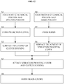
- Fig. 12 is a flow chart showing a procedure for processing and assembly of the clutch housing 31 and vibration proofing cover 51.
- Step S1 Form first cylindrical portion 32 and bottom portion 41
- the bottom portion 41 and first cylindrical portion 32 are formed. Specifically, the bottom portion 41 and first cylindrical portion 32 are formed by press processing.
- the plastic processing (press processing) is deep drawing, for example.
- the bottom portion 41 and first cylindrical portion 32 are formed by press processing of flat plate, for example.
- the bottom portion 41 and first cylindrical portion 32 constitute an integrated whole.
- Step S2 Form projections 71
- the projections 71 are formed. Specifically, the projections 71 are formed by plastic processing (press processing). The press processing is half pierce, for example. Simultaneously with the forming of the projections 71, the recesses 73 are formed in the bottom portion 41.
- first openings 42 are formed. Specifically, the first openings 42 are formed in the bottom portion 41 by shear processing (press processing).
- the press processing is punching, for example.
- the heads 72 are not yet formed in step S2.
- Step S3 Surface treatment of the clutch housing 31
- the clutch housing 31 is surface-treated.
- the clutch housing 31 is surface-treated in a state not having the vibration proofing cover 51 attached thereto.
- Step S4 Form second cylindrical portion 52 and fixed portion 61
- the second cylindrical portion 52 and fixed portion 61 are formed. Specifically, the second cylindrical portion 52 and fixed portion 61 are formed by press processing. The press processing is deep drawing, for example. The second cylindrical portion 52 and fixed portion 61 are formed by press processing of flat plate, for example. The second cylindrical portion 52 and fixed portion 61 constitute an integrated whole.
- Step S5 Form bores 65
- the bores 65 are formed. Specifically, the bores 65 are formed in the fixed portion 61 by press processing.
- the press processing is punching, for example.
- the second opening 62 is formed. Specifically, the second opening 62 is formed in the fixed portion 61 by pierce processing.
- the bores 65 and second opening 62 are formed at the same time.
- the bores 65 and second opening 62 are formed by one plastic processing (press processing).
- Step S6 Surface treatment of vibration proofing cover 51
- the vibration proofing cover 51 is surface-treated.
- the vibration proofing cover 51 is surface-treated in a state where the clutch housing 31 is not attached to the vibration proofing cover 51.
- Step S7 Attach vibration proofing cover 51 and clutch housing 31
- the vibration proofing cover 51 is attached to the clutch housing 31. Specifically, the vibration proofing cover 51 is pressed onto the clutch housing 31. The vibration proofing cover 51 is fitted outside the clutch housing 31. Consequently, the second cylindrical portion 52 contacts part of the first cylindrical portion 32. The second cylindrical portion 52 presses on part of the first cylindrical portion 32. The fixed portion 61 contacts the bottom portion 41. The projections 71 are placed in the bores 65. The projections 71 penetrate the fixed portion 61. The distal ends 71b of the projections 71 project from the fixed portion 61.
- Step S8 Form (crimp) heads 72
- the heads 72 are formed. Specifically, the heads 72 are formed by plastic processing (press processing). The plastic processing is heading or spinning, for example. By forming of the heads 72, the fixed portion 61 is crimped to the bottom portion 41.
- step S2 is executed after step S1.
- at least part of step S2 may be executed before at least part of step S1.
- at least part of step S2 may be executed simultaneously with at least part of step S1.
- at least part of step S2 may be executed after at least part of step S1.
- Step S3 is executed after steps S1 and S2.
- step S5 is executed after step S4.
- at least part of step S5 may be executed before at least part of step S4.
- at least part of step S5 may be executed simultaneously with at least part of step S4.
- at least part of step S5 may be executed after at least part of step S4.
- Step S6 is executed after steps S4 and S5.
- steps S1-S3 and steps S4-S6 there is no restriction on the temporal order between steps S1-S3 and steps S4-S6.
- steps S1-S3 may be executed before at least part of steps S4-S6.
- steps S1-S3 may be executed simultaneously with at least part of steps S4-S6.
- at least part of steps S1-S3 may be executed after at least part of steps S4-S6.
- Step S7 is executed after steps S1-S6.
- Step S8 is executed after step S7.
- the centrifugal clutch 21 includes centrifugal shoes 22.
- the centrifugal shoes 22 revolve about the axis A2.
- the centrifugal shoes 22 are movable by centrifugal force radially outward of the axis A2.
- the centrifugal clutch 22 includes a clutch housing 31.
- the clutch housing 31 has a first cylindrical portion 32.
- the first cylindrical portion 32 is located radially outward of the axis A2 relative to the centrifugal shoes 22.
- the first cylindrical portion 32 can contact the centrifugal shoes 22. This can appropriately connect power transmission between the centrifugal shoes 22 and clutch housing 31.
- the first cylindrical portion 32 can separate from the centrifugal shoes 22. This can appropriately cut power transmission between the centrifugal shoes 22 and clutch housing 31.
- the centrifugal clutch 21 includes a vibration proofing cover 51.
- the vibration proofing cover 51 has a second cylindrical portion 52.
- the second cylindrical portion 52 is located radially outward of the axis A2 relative to the first cylindrical portion 32.
- the second cylindrical portion 52 contacts part of the first cylindrical portion 32.
- the vibration proofing cover 51 can therefore appropriately suppress vibration of the first cylindrical portion 32.
- the clutch housing 31 has a bottom portion 41.
- the bottom portion 41 extends from the first cylindrical portion 32 radially inward of the axis A2.
- the vibration proofing cover 51 has a fixed portion 61.
- the fixed portion 61 extends from the second cylindrical portion 52 radially inward of the axis A2.
- the fixed portion 61 is crimped to the bottom portion 41.
- the clutch housing 31 and vibration proofing cover 51 can therefore appropriately be fixed together. Specifically, the clutch housing 31 and vibration proofing cover 51 can appropriately be joined together, not by fusion welding (welding).
- the fixed portion 61 is fixed to the bottom portion 41 by plastic processing.
- the clutch housing 31 and vibration proofing cover 51 can therefore appropriately be joined together.
- the fixed portion 61 is fixed to the bottom portion 41 by press processing.
- the clutch housing 31 and vibration proofing cover 51 can therefore appropriately be joined together.
- the centrifugal clutch 21 includes projections 71 and heads 72.
- the projections 71 penetrate the fixed portion 61.
- the heads 72 are connected to the projections 71.
- the heads 72 press the fixed portion 61 on the bottom portion 41.
- the fixed portion 61 and bottom portion 41 can therefore be appropriately fixed together.
- the projections 71 extend parallel to the axis A2.
- the bottom portion 41, the fixed portion 61, and the heads 72 are arranged in the stated order axially of the axis A2.
- the projections 71 can appropriately penetrate the fixed portion 61.
- the projections 71 can appropriately join the heads 72.
- the fixed portion 61 contacts the bottom portion 41.
- the fixed portion 61 contacts the heads 72. At least part of the heads 72 overlap both the fixed portion 61 and the bottom portion 41 as seen from the axis A2.
- the heads 72 can therefore appropriately press the fixed portion 61 on the bottom portion 41.
- the projections 71 and the heads 72 are integrated with the bottom portion 41. This can simplify the construction of the centrifugal clutch 21.
- the bottom portion 41 has a thickness T41 larger than a thickness T61 of the fixed portion 61.
- the projections 71 and heads 72 can be formed appropriately.
- the projections 71 can have a length L71 enough to penetrate the fixed portion 61.
- the heads 72 can be arranged in positions capable of appropriately pressing the fixed portion 61 on the bottom portion 41.
- the bottom portion 41 has recesses 73 arranged on back sides of the projections 71.
- the projections 71 are formed to project from the bottom portion 41 simultaneously with formation of the recesses 73.
- the projections 71 can be formed conveniently.
- the projections 71 have an outside diameter D71 smaller than an inside diameter D73 of the recesses 73. Therefore, the length L71 of the projections 71 can easily be secured. Specifically, an initial length L71 i of the projections 71 can easily be made larger than the thickness T61 of the fixed portion 61. The projections 71 can therefore penetrate the fixed portion 61 conveniently. On the other hand, the inside diameter D73 of the recesses 73 is larger than the outside diameter D71 of the projections 71. Therefore, the depth L73 of the recesses 73 can easily be made small. This can prevent excessive lowering of the strength of the bottom portion 41.
- the depth L73 of the recesses 73 is smaller than the thickness T41 of the bottom portion 41. This can conveniently secure the strength of the bottom portion 41.
- the heads 72 are formed by applying a load to distal ends 71b of the projections 71.
- the heads 72 can therefore be conveniently formed.
- the heads 72 are formed by crushing the distal ends 71b of the projections 71.
- the heads 72 can therefore be conveniently formed.
- the heads 72 are formed after the vibration proofing cover 51 is attached to the clutch housing 31.
- the heads 72 can therefore conveniently press the fixed portion 61 on the bottom portion 41.
- the clutch housing 31 is surface-treated.
- the functions of the clutch housing 31 can be improved conveniently.
- the characteristics of friction between the clutch housing 31 and centrifugal shoes 22 can be improved.
- the affinity of friction between the clutch housing 31 and centrifugal shoes 22 can be improved.
- the rust prevention of the clutch housing 31 can be improved.
- the clutch housing 31 is given nitriding treatment.
- the characteristics of friction between the clutch housing 31 and centrifugal shoes 22 can be improved effectively.
- the affinity of friction between the clutch housing 31 and centrifugal shoes 22 can be improved effectively.
- the rust prevention of the clutch housing 31 can be improved effectively.
- the vibration proofing cover 51 is surface-treated.
- the functions of the vibration proofing cover 51 can be improved conveniently.
- the rust prevention of the vibration proofing cover 51 can be improved.
- the vibration proofing cover 51 is given nitriding treatment.
- the rust prevention of the vibration proofing cover 51 can be improved effectively.
- the clutch housing 31 is surface-treated in a state not attached to the vibration proofing cover 51 (step S3).
- the vibration proofing cover 51 is attached to the clutch housing 31 after the clutch housing 31 is surface-treated (step S7). Consequently, after the surface treatment of the clutch housing 31 and before the vibration proofing cover 51 is attached to the clutch housing 31, the dimensions of the clutch housing 31 can be controlled with high accuracy.
- the accuracy of the relative position between the clutch housing 31 and vibration proofing cover 51 can therefore be secured conveniently. In other words, when attaching the vibration proofing cover 51 to the clutch housing 31, the positional adjustment of the clutch housing 31 and vibration proofing cover 51 can be performed with high accuracy. In particular, the accuracy of the relative position between the first cylindrical portion 32 and second cylindrical portion 52 can be secured conveniently.
- the positional adjustment of the first cylindrical portion 32 and second cylindrical portion 52 can be performed with high accuracy.
- the contact portions 35 of the first cylindrical portion 32 can be made to appropriately contact the second cylindrical portion 52.
- the non-contact portions 36 of the first cylindrical portion 32 can be appropriately spaced from the second cylindrical portion 52.
- the gaps 60 can be appropriately formed between the first cylindrical portion 32 and second cylindrical portion 52. As a result, vibration of the first cylindrical portion 32 can be suppressed conveniently.
- the surface treatment includes heat treatment.
- the clutch housing 31 may be distorted. It is difficult to correct the distortion of the clutch housing 31 in a state where the vibration proofing cover 51 is attached to the clutch housing 31. Consequently, if the surface treatment of the clutch housing 31 were carried out in the state where the vibration proofing cover 51 is attached to the clutch housing 31, it would be difficult to secure the accuracy of the relative position between the clutch housing 31 and vibration proofing cover 51. And if the accuracy of the relative position between the clutch housing 31 and vibration proofing cover 51 should lower, it would be difficult to suppress vibration of the first cylindrical portion 32.
- the fixation between the fixed portion 61 and bottom portion 41 is performed after surface treatment of the clutch housing 31.
- the clutch housing 31 after surface treatment can be unsuitable for welding.
- welding is not used for fixation between the fixed portion 61 and bottom portion 41.
- the fixed portion 61 and bottom portion 41 are not fusion-joined together.
- the fixed portion 61 and bottom portion 41 are joined by non-welding means. Therefore, the fixed portion 61 and bottom portion 41 can easily be fixed together.
- the centrifugal clutch 21 in this embodiment has particularly high utility.
- the centrifugal clutch 21 in this embodiment has particularly high utility.
- the vibration proofing cover 51 is surface-treated in a state not attached to the clutch housing 31 (step S6).
- the vibration proofing cover 51 is attached to the clutch housing 31 after the vibration proofing cover 51 is surface-treated (step S7). Consequently, after the surface treatment of the vibration proofing cover 51 and before the vibration proofing cover 51 is attached to the clutch housing 31, the dimensions of the vibration proofing cover 51 can be controlled with high accuracy.
- the accuracy of the relative position between the clutch housing 31 and vibration proofing cover 51 can therefore be secured conveniently. In other words, when attaching the vibration proofing cover 51 to the clutch housing 31, the positional adjustment of the clutch housing 31 and vibration proofing cover 51 can be performed with high accuracy. In particular, the accuracy of the relative position between the first cylindrical portion 32 and second cylindrical portion 52 can be secured conveniently.
- the positional adjustment of the first cylindrical portion 32 and second cylindrical portion 52 can be performed with high accuracy.
- the first contact portions 55 and second contact portions 58 of the second cylindrical portion 52 can be made to appropriately contact the first cylindrical portion 32.
- the first non-contact portions 57 and second non-contact portions 59 of the second cylindrical portion 52 can be appropriately separated from the first cylindrical portion 32.
- the gaps 60 can be appropriately formed between the first cylindrical portion 32 and second cylindrical portion 52.
- the second cylindrical portion 52 can conveniently suppress vibration of the first cylindrical portion 32.
- the surface treatment includes heat treatment.
- the vibration proofing cover 51 may be distorted. It is difficult to correct the distortion of the vibration proofing cover 51 in a state where the vibration proofing cover 51 is attached to the clutch housing 31. Consequently, if the surface treatment of the vibration proofing cover 51 were carried out in the state where the vibration proofing cover 51 is attached to the clutch housing 31, it would be difficult to secure the accuracy of the relative position between the clutch housing 31 and vibration proofing cover 51. And if the accuracy of the relative position between the clutch housing 31 and vibration proofing cover 51 should lower, it would be difficult for the vibration proofing cover 51 to suppress vibration of the first cylindrical portion 32.
- the fixation between the fixed portion 61 and bottom portion 41 is performed after surface treatment of the vibration proofing cover 51.
- the vibration proofing cover 51 after surface treatment can be unsuitable for welding.
- welding is not used for fixation between the fixed portion 61 and bottom portion 41.
- the fixed portion 61 and bottom portion 41 are not fusion-welded together.
- the fixed portion 61 and bottom portion 41 are joined by non-welding means. Therefore, the fixed portion 61 and bottom portion 41 can easily be fixed together.
- the centrifugal clutch 21 in this embodiment has particularly high utility.
- the vibration proofing cover 51 when the surface treatment of the vibration proofing cover 51 is nitriding treatment, the electric resistance of the vibration proofing cover 51 is relatively high. Therefore, the vibration proofing cover 51 after nitriding treatment is unsuitable for welding. For example, in order to weld the fixed portion 61 and bottom portion 41, a relatively high voltage is required. Thus, where nitriding treatment of the vibration proofing cover 51 is carried out, the centrifugal clutch 21 in this embodiment has particularly high utility.
- the initial length L71i of the projections 71 is larger than the thickness T61 of the fixed portion 61. Therefore, when the vibration proofing cover 51 is attached to the clutch housing 31 (step S7), the distal ends 71b of the projections 71 project from the fixed portion 61. Thus, the heads 72 can be formed conveniently.
- the final length L71f of the projections 71 is substantially the same as the thickness T61 of the fixed portion 61.
- the heads 72 can therefore conveniently contact the fixed portion 61.
- the bottom portion 41 can also conveniently contact the fixed portion 61.
- the outside diameter D72 of the heads 72 is larger than the inside diameter D65 of the bores 65.
- the heads 72 can thus conveniently press the fixed portion 61 on the bottom portion 41.
- the depth L73 of the recesses 73 is smaller than the initial length L71i of the projections 71. Thus, the strength of the bottom portion 41 can be secured conveniently.
- the inside diameter D73 of the recesses 73 is larger than the depth L73 of the recesses 73. Therefore, the depth L73 of the recesses 73 can easily be made small. Thus, the strength of the bottom portion 41 can be secured conveniently.
- step S3 the surface treatment of the clutch housing 31 is performed. That is, the projections 71 are formed before the clutch housing 31 is surface-treated. The projections 71 can therefore be formed easily. Specifically, the bottom portion 41 not surface-treated is put to plastic deformation. The plastic deformation of the bottom portion 41 can therefore be carried out easily.
- the clutch housing 31 hardens by the surface treatment of the clutch housing 31.
- the external force for forming the projections 71 after the surface treatment is larger than the external force for forming the projections 71 before the surface treatment. It is therefore easier to form the projections 71 before the surface treatment than forming the projections 71 after the surface treatment.
- the centrifugal clutch 21 in this embodiment has particularly high utility.
- the bores 65 and second opening 62 are formed at the same time.
- the bores 65 and second opening 62 are formed by one plastic processing (press processing). This can conveniently prevent variations of the relative position between the bores 65 and second opening 62. Further, the number of steps of the plastic processing (press processing) can be reduced.
- the second cylindrical portion 52 presses on part of the first cylindrical portion 32.
- the first cylindrical portion 32 and second cylindrical portion 52 contact each other with an appropriate frictional force.
- the frictional force between the first cylindrical portion 32 and second cylindrical portion 52 can effectively suppress vibration of the first cylindrical portion 32.
- the straddled vehicle 1 includes the centrifugal clutch 21 described above. According to the straddled vehicle 1, the clutch housing 31 and vibration proofing cover 51 can be joined together appropriately.
Landscapes
- Engineering & Computer Science (AREA)
- General Engineering & Computer Science (AREA)
- Mechanical Engineering (AREA)
- One-Way And Automatic Clutches, And Combinations Of Different Clutches (AREA)
- Vibration Prevention Devices (AREA)
Abstract
Description
- This invention relates to a centrifugal clutch and a straddled vehicle having the centrifugal clutch.
-
Japanese Unexamined Patent Publication No. 2006-71096 - The centrifugal clutch (11) has a vibration proofing cover (17). The vibration proofing cover (17) has a side edge (17a) and a bottom (17b). The side edge (17a) has projections (22). The projections (22) contact the cylindrical portion (12a). The bottom (17b) is melt-joined by spot welding to the bottom plate (12b). Here, spot welding is resistance welding.
- The centrifugal clutch is required to provide the following functions, for example:
- a) friction characteristics between the clutch housing and centrifugal shoes;
- b) suppressing vibration of the clutch housing;
- c) preventing rusting of the clutch housing; and
- d) preventing rusting of the vibration proofing cover.
- In order to improve these functions, Inventors herein have studied property modifications of the surfaces of the clutch housing, and property modifications of the surfaces of the vibration proofing cover, for example.
- As a result of these studies, Inventors have found a new problem. Specifically, Inventors have found that a new problem arises from property modifications of at least either the surfaces of the clutch housing or the surfaces of the vibration proofing cover. The new problem is that there is a possibility of resistance welding becoming unsuitable for fusion joining between the clutch housing and vibration proofing cover. For example, the quality of resistance welding becomes difficult to secure. For example, the set tolerance range of non-defective product conditions in resistance welding becomes narrow. Further, fusion zone can become unstable even when the current, weld time, load, and so on are made constant. Consequently, the electrode used in resistance welding can be markedly worn, thereby to shorten the life of the electrode. When the electrode used in resistance welding wears easily, there arises a concern about the fusion zone becoming still more unstable.
- This invention has been made having regard to the state of the art noted above, and its object is to provide a centrifugal clutch capable of appropriately joining a clutch housing and a vibration proofing cover, and a straddled vehicle having such centrifugal clutch.
- In order to fulfill the above object, a centrifugal clutch according to
claim 1 is provided. This invention provides the following construction. - A centrifugal clutch according to this invention comprises:
- centrifugal shoes revolvable about a first axis and movable by centrifugal force radially outward of the first axis;
- a clutch housing having a first cylindrical portion located radially outward of the first axis relative to the centrifugal shoes to be capable of contacting and separating from the centrifugal shoes, and a bottom portion extending from the first cylindrical portion radially inward of the first axis; and
- a vibration proofing cover having a second cylindrical portion located radially outward of the first axis relative to the first cylindrical portion and in contact with part of the first cylindrical portion, and a fixed portion extending from the second cylindrical portion radially inward of the first axis and crimped to the bottom portion.
- The centrifugal clutch includes centrifugal shoes. The centrifugal shoes revolve about the first axis. The centrifugal shoes are movable by centrifugal force radially outward of the first axis. The centrifugal clutch includes a clutch housing. The clutch housing has a first cylindrical portion. The first cylindrical portion is located radially outward of the first axis relative to the centrifugal shoes. The first cylindrical portion can contact the centrifugal shoes. This can appropriately engage power transmission between the centrifugal shoes and clutch housing. The first cylindrical portion can separate from the centrifugal shoes. This can appropriately disengage power transmission between the centrifugal shoes and clutch housing.
- The centrifugal clutch includes a vibration proofing cover. The vibration proofing cover has a second cylindrical portion. The second cylindrical portion is located radially outward of the first axis relative to the first cylindrical portion. The second cylindrical portion contacts part of the first cylindrical portion. The vibration proofing cover can therefore appropriately suppress vibration of the first cylindrical portion.
- The clutch housing has a bottom portion. The bottom portion extends from the first cylindrical portion radially inward toward the first axis. The vibration proofing cover has a fixed portion. The fixed portion extends from the second cylindrical portion radially inward toward the first axis. The fixed portion is crimped to the bottom portion. The clutch housing and the vibration proofing cover can therefore appropriately be joined together.
- In the above centrifugal clutch, it is preferred that the fixed portion is fixed to the bottom portion by plastic processing.
The plastic processing can appropriately fix the clutch housing and vibration proofing cover together. - In the above centrifugal clutch, it is preferred that the fixed portion is fixed to the bottom portion by press processing.
The press processing can appropriately fix the clutch housing and vibration proofing cover together. - It is preferred that the above centrifugal clutch comprises:
- pins penetrating the fixed portion; and
- heads connected to the pins for pressing the fixed portion on the bottom portion.
- In the above centrifugal clutch, it is preferred that:
- the pins extend parallel to the first axis;
- the bottom portion, the fixed portion, and the heads are arranged in the stated order axially of the first axis;
- the fixed portion contacts the bottom portion and the heads; and
- at least part of the heads overlap both the fixed portion and the bottom portion as seen from the first axis.
- In the above centrifugal clutch, it is preferred that the pins and the heads are integrated with the bottom portion.
This can simplify the construction of the centrifugal clutch. - In the above centrifugal clutch, it is preferred that the bottom portion has a thickness larger than a thickness of the fixed portion.
The pins and the heads are integrated with the bottom portion. The pins and the heads can be provided appropriately. More particularly, since the thickness of the bottom portion is relatively large, the pins and the heads can easily be integrated with the bottom portion. For example, the pins and the heads can be formed appropriately. - In the above centrifugal clutch, it is preferred that the bottom portion has recesses arranged on back sides of the pins; and
the pins are formed to project from the bottom portion simultaneously with formation of the recesses.
The pins can be formed conveniently. - In the above centrifugal clutch, it is preferred that the pins have an outside diameter smaller than an inside diameter of the recesses.
The outside diameter of the pins is smaller than the inside diameter of the recesses. Therefore, for example, the length of the pins can easily be secured by plastic deformation of the material. The pins can therefore penetrate the fixed portion conveniently. On the other hand, the inside diameter of the recesses is larger than the outside diameter of the pins. Therefore, the depth of the recesses can easily be made small. This can prevent excessive lowering of the strength of the bottom portion. - In the above centrifugal clutch, it is preferred that the recesses have a depth smaller than the thickness of the bottom portion.
This can conveniently secure the strength of the bottom portion. - In the above centrifugal clutch, it is preferred that the heads are formed by applying load to distal ends of the pins.
The heads can conveniently formed by crimping. - In the above centrifugal clutch, it is preferred that the heads are formed after the vibration proofing cover is attached to the clutch housing.
The heads can conveniently cause the fixed portion to contact the bottom portion. Further, the heads can conveniently press the fixed portion on the bottom portion. - In the above centrifugal clutch, it is preferred that at least one of the clutch housing and the vibration proofing cover is surface-treated.
Surface treatment can be performed as necessary for at least one of the clutch housing and the vibration proofing cover. This can conveniently improve the function of the centrifugal clutch. - In the above centrifugal clutch, it can be preferable that at least one of the clutch housing and the vibration proofing cover is not surface-treated.
In certain cases, the function of the centrifugal clutch can conveniently be improved by giving no surface treatment to at least one of the clutch housing and the vibration proofing cover. - In the above centrifugal clutch, it is preferred that:
- the clutch housing is surface-treated in a state not attached to the vibration proofing cover; and
- the vibration proofing cover is attached to the clutch housing after the clutch housing is surface-treated.
- In the above centrifugal clutch, it is preferred that:
- the vibration proofing cover is surface-treated in a state not attached to the clutch housing; and
- the vibration proofing cover is attached to the clutch housing after the vibration proofing cover is surface-treated.
- This invention also provides a straddled vehicle comprising the centrifugal clutch as described above.
- According to this straddled vehicle, the clutch housing and vibration proofing cover can be joined together appropriately. Furthermore, the present invention also considers any method for manufacturing a centrifugal clutch according to the above aspects by any of the above method related features.
- For the purpose of illustrating the invention, there are shown in the drawings several forms which are presently preferred, it being understood, however, that the invention is not limited to the precise arrangement and instrumentalities shown.
-
Fig. 1 is a left side view of a straddled vehicle according to an embodiment. -
Fig. 2 is a horizontal sectional view of a transmission. -
Fig. 3 is a view of centrifugal shoes seen axially of a second output shaft. -
Fig. 4A is a horizontal sectional view of a clutch housing. -
Fig. 4B is a view of the clutch housing seen from direction B shown inFig. 4A . -
Fig. 5A is a horizontal sectional view of a vibration proofing cover. -
Fig. 5B is a view of the vibration proofing cover seen from direction B shown inFig. 5A . -
Fig. 6A is a horizontal sectional view of the clutch housing and vibration proofing cover. -
Fig. 6B is a view of the clutch housing and vibration proofing cover seen from direction B1 shown inFig. 6A . -
Fig. 7 is a view of the clutch housing and vibration proofing cover seen from direction B2 shown inFig. 6A . -
Fig. 8 is a sectional view taken on line VIII-VIII ofFig. 6B . -
Fig. 9 is a sectional view showing forming of the clutch housing. -
Fig. 10 is a sectional view of the vibration proofing cover. -
Fig. 11 is a sectional view schematically showing the clutch housing and vibration proofing cover (including surface treatment). -
Fig. 12 is a flow chart showing a procedure for processing and assembly of the clutch housing and vibration proofing cover. -
Fig. 13 is a sectional view illustrating crimps between a bottom portion and a fixed portion in a modified embodiment. -
Fig. 14 is a sectional view illustrating crimps between the bottom portion and fixed portion in a modified embodiment. - A straddled
vehicle 1 according to this invention will be described hereinafter with reference to the drawings. -
Fig. 1 is a left side view of a straddled vehicle according to an embodiment. -
Fig. 1 shows a longitudinal direction X, a transverse direction Y, and an up-down direction Z of the straddledvehicle 1. The longitudinal direction X, transverse direction Y, and up-down direction Z are defined with reference to the driver (or rider) mounted on the straddledvehicle 1. The longitudinal direction X, transverse direction Y, and up-down direction Z are perpendicular to one another. The longitudinal direction X and transverse direction Y are horizontal. The up-down direction Z is vertical. - The terms "forward", "rearward", "upward", "downward", "rightward", and "leftward", respectively mean "forward", "rearward", "upward", "downward", "rightward", and "leftward" as seen from the driver mounted on the straddled
vehicle 1. Unless otherwise stated in this specification, "forward" and "rearward" include not only directions parallel to the longitudinal direction X but also directions approximate to the longitudinal direction X. The directions approximate to the longitudinal direction X are, for example, directions at angles not exceeding 45 degrees to the longitudinal direction X. Similarly, unless otherwise stated, "rightward" and "leftward" include not only directions parallel to the transverse direction Y but also directions approximate to the transverse direction Y. Unless otherwise stated, the "upward" and "downward" include not only directions parallel to the up-down direction Z but also directions approximate to the up-down direction Z. For reference, the drawings show front, rear, up, down, right, and left, as appropriate. - This specification uses various expressions describing arrangements, which have the following meanings, respectively. The following description will be made taking the transverse direction Y for example, and the same may be applied to the longitudinal direction X and up-down direction Z.
- The expression "Member Ma is located more rightward/leftward than member Mb," defines a position in the transverse direction Y of member Ma relative to member Mb, and does not define a position in the longitudinal direction X or the up-down direction Z of member Ma relative to member Mb. In the case of this expression, member Ma may, or may not, overlap member Mb in a side view of the vehicle.
- The expression "Member Ma is located rightward/leftward of member Mb," without reference to a looking direction defines a position in the transverse direction Y of member Ma relative to member Mb, a position in the longitudinal direction X of member Ma relative to member Mb, and a position in the up-down direction Z of member Ma relative to member Mb. This expression means that member Ma is located more rightward/leftward than member Mb, and that at least part of member Ma overlaps at least part of member Mb in a side view of the vehicle.
- The expression "Member Ma is located rightward/leftward of member Mb in a plan view of the vehicle," defines a position in the transverse direction Y of member Ma relative to member Mb, and a position in the longitudinal direction X of member Ma relative to member Mb, and does not define a position in the up-down direction Z of member Ma relative to member Mb. This expression means that member Ma is located more rightward/leftward than member Mb, and that the front end of member Ma is located more forward than the rear end of member Mb, and that the rear end of member Ma is located more rearward than the front end of member Mb.
- The expression "Member Ma is located rightward/leftward of member Mb in a front view of the vehicle," defines a position in the transverse direction Y of member Ma relative to member Mb, and a position in the up-down direction Z of member Ma relative to member Mb, and does not define a position in the longitudinal direction X of member Ma relative to member Mb. This expression means that member Ma is located more rightward/leftward than member Mb, that the upper end of member Ma is located higher than the lower end of member Mb, and that the lower end of member Ma is located lower than the upper end of member Mb.
- The straddled
vehicle 1 is a scooter type vehicle. - The straddled
vehicle 1 includes afront fork 2, afront wheel 3, and ahandlebar 4. Thefront fork 2 is disposed at the front of the straddledvehicle 1. Thefront wheel 3 is supported by thefront fork 2. Thehandlebar 4 is supported by thefront fork 2. Thehandlebar 4 is located higher than thefront wheel 3. The driver grasps thehandlebar 4. - The straddled
vehicle 1 includes aseat 5. Theseat 5 is located more rearward than thehandlebar 4. The driver sits on theseat 5. - The straddled
vehicle 1 includes anengine 6, atransmission 8, and arear wheel 9. Theengine 6 is located below theseat 5. Thetransmission 8 is located behind theengine 6. Therear wheel 9 is supported by thetransmission 8. - The straddled
vehicle 1 includes a body frame not shown. The body frame supports thefront fork 2,seat 5,engine 6, andtransmission 8. - The
engine 6 generates power. Thetransmission 8 transmits power from theengine 6 to therear wheel 9. -
Fig. 2 is a horizontal sectional view of thetransmission 8. Theengine 6 outputs rotational power. Specifically, theengine 6 has afirst output shaft 7. Thefirst output shaft 7 outputs the rotational power. The straddledvehicle 1 includes arear axle 10. Therear axle 10 transmits power to therear wheel 9 through gears and a reduction device. Therear wheel 9 is rotatable with therear axle 10, for example. Thetransmission 8 transmits the rotational power from thefirst output shaft 7 to therear axle 10. Therear wheel 9 is rotated by the power transmitted to therear axle 10. - The
transmission 8 has aspeed changer 11. Thespeed changer 11 receives the rotational power from thefirst output shaft 7. Thespeed changer 11 changes rotation speed of the rotational power inputted to thespeed changer 11. Thespeed changer 11 outputs the rotational power at rotation speeds changed. - The
transmission 8 has acentrifugal clutch 21. The centrifugal clutch 21 receives the rotational power from thespeed changer 11. The centrifugal clutch 21 uses centrifugal force to switch between an engaged state and a disengaged state. When the centrifugal clutch 21 is in the engaged state, the centrifugal clutch 21 transmits the rotational power from thespeed changer 11 to therear axle 10. When the centrifugal clutch 21 is in the disengaged state, the centrifugal clutch 21 does not transmit the rotational power from thespeed changer 11 to therear axle 10. - The constructions of the
first output shaft 7,speed changer 11, centrifugal clutch 21, andrear axle 10 will be described specifically. Thefirst output shaft 7 is a crankshaft, for example. Thefirst output shaft 7 has an axis A1. The axis A1 is an imaginary straight line passing through the center of thefirst output shaft 7. The axis A1 is parallel to the transverse direction Y, for example. Thefirst output shaft 7 rotates about the axis A1. - The
speed changer 11 is connected to thefirst output shaft 7. The rotational power of thefirst output shaft 7 is inputted to thespeed changer 11. - The
speed changer 11 has asecond output shaft 12. Thesecond output shaft 12 outputs rotational power. Thesecond output shaft 12 has an axis A2. The axis A2 is an imaginary straight line passing through the center of thesecond output shaft 12. The axis A2 is parallel to the axis A1, for example. The axis A2 is parallel to the transverse direction Y, for example. Thesecond output shaft 12 rotates about the axis A2. - The
speed changer 11 is a stepless speed change device. The stepless speed change device is also called a continuously variable transmission. Thespeed changer 11 continuously changes speed change ratio. The speed change ratio is also called gear ratio. The speed change ratio is a ratio between rotation speed of thefirst output shaft 7 and rotation speed of thesecond output shaft 12. - The
speed changer 11 has afirst pulley 15, asecond pulley 16, and abelt 17. Thefirst pulley 15 is mounted on thefirst output shaft 7. Thefirst pulley 15 is rotatable with thefirst output shaft 7. Thefirst pulley 15 rotates about the axis A1 of thefirst output shaft 7. Thefirst pulley 15 receives the rotational power of thefirst output shaft 7. Thesecond output shaft 12 is, in plan view, located behind thefirst output shaft 7. Thesecond output shaft 12 has a tubular shape. Thesecond output shaft 12 has ahollow portion 13. Thehollow portion 13 is formed inside thesecond output shaft 12. Thesecond pulley 16 is mounted on thesecond output shaft 12. Thesecond pulley 16 is rotatable with thesecond output shaft 12. Thesecond pulley 16 rotates about the axis A2 of thesecond output shaft 12. Thebelt 17 is an endless belt. Thebelt 17 is wound around thefirst pulley 15 andsecond pulley 16. Thebelt 17 connects thefirst pulley 15 andsecond pulley 16. Thebelt 17 transmits the rotational power of thefirst pulley 15 to thesecond pulley 16 andsecond output shaft 12. - The
first pulley 15 can continuously change the effective diameter of thefirst pulley 15. Thesecond pulley 16 can also continuously change the effective diameter of thesecond pulley 16. The speed change ratio of thespeed changer 11 changes as the effective diameter of thefirst pulley 15 and the effective diameter of thesecond pulley 16 change. Here, the effective diameter of thefirst pulley 15 is the diameter in a portion of thefirst pulley 15 that contacts thebelt 17. The effective diameter of thesecond pulley 16 is the diameter in a portion of thesecond pulley 16 that contacts thebelt 17. -
Fig. 2 shows thefirst pulley 15,second pulley 16, andbelt 17 in solid lines when the effective diameter of thefirst pulley 15 is relatively small.Fig. 2 shows thefirst pulley 15,second pulley 16, andbelt 17 in broken lines when the effective diameter of thefirst pulley 15 is relatively large. The effective diameter of thesecond pulley 16 becomes smaller as the effective diameter of thefirst pulley 15 becomes larger. - Specifically, the
first pulley 15 has a first fixedsheave 15a and a firstmovable sheave 15b. The first fixedsheave 15a and firstmovable sheave 15b are arranged side by side along the axis A1. Thebelt 17 is located between the first fixedsheave 15a and firstmovable sheave 15b. The spacing along the axis A1 between the first fixedsheave 15a and firstmovable sheave 15b enlarges radially outward from the axis A1. The first fixedsheave 15a is not slidable along the axis A1. The firstmovable sheave 15b is slidable along the axis A1. The effective diameter of thefirst pulley 15 changes with movement of the firstmovable sheave 15b along the axis A1. The smaller the spacing between the first fixedsheave 15a and firstmovable sheave 15b becomes, the larger becomes the effective diameter of thefirst pulley 15. - The
second pulley 16 has a second fixedsheave 16a and a secondmovable sheave 16b. The second fixedsheave 16a and secondmovable sheave 16b are arranged side by side along the axis A2. Thebelt 17 is located between the second fixedsheave 16a and secondmovable sheave 16b. The spacing along the axis A2 between the second fixedsheave 16a and secondmovable sheave 16b enlarges radially outward from the axis A2. The second fixedsheave 16a is not slidable along the axis A2. The secondmovable sheave 16b is slidable along the axis A2. The effective diameter of thesecond pulley 16 changes with movement of the secondmovable sheave 16b along the axis A2. The smaller the spacing between the second fixedsheave 16a and secondmovable sheave 16b becomes, the larger becomes the effective diameter of thesecond pulley 16. - Here, radial directions of the axis A2 are perpendicular to the axis A2. The phrase "radially outward of the axis" signifies directions perpendicular to the axis A2 and pointing away from the axis A2. The phrase "radially outward from the axis A2" also signifies directions perpendicular to the axis A2 and pointing away from the axis A2. The phrase "radially inward of the axis A2" signifies directions perpendicular to the axis A2 and approaching the axis A2. The phrase "radially inward toward the axis A2" also signifies directions perpendicular to the axis A2 and approaching the axis A2.
- The centrifugal clutch 21 has one or more (e.g. three)
centrifugal shoes 22. Thecentrifugal shoes 22 are connected to thesecond output shaft 12. Thecentrifugal shoes 22 are revolvable with thesecond output shaft 12. Thecentrifugal shoes 22 revolve about the axis A2. Thecentrifugal shoes 22 receive the rotational power of thesecond output shaft 12. - The
centrifugal shoes 22 are movable by centrifugal force radially of the axis A2. When thecentrifugal shoes 22 revolve about the axis A2, centrifugal force acts on thecentrifugal shoes 22. The centrifugal force acting on thecentrifugal shoes 22 becomes larger with increase in the revolving speed of thecentrifugal shoes 22 about the axis A2. As the centrifugal force becomes larger, thecentrifugal shoes 22 move radially outward from the axis A2. As the centrifugal force becomes smaller, thecentrifugal shoes 22 move radially inward toward the axis A2. When thecentrifugal shoes 22 do not revolve about the axis A2, centrifugal force does not act on thecentrifugal shoes 22. - The axis A2 is an example of the first axis in this invention.
- The centrifugal clutch 21 includes a
clutch housing 31. Theclutch housing 31 has a firstcylindrical portion 32. The firstcylindrical portion 32 is located radially outward of the axis A2 relative to thecentrifugal shoes 22. The firstcylindrical portion 32 can contact thecentrifugal shoes 22, and can separate from thecentrifugal shoes 22. - The first
cylindrical portion 32 overlaps thecentrifugal shoes 22 when seen radially of the axis A2. The firstcylindrical portion 32 circumferentially surrounds thecentrifugal shoes 22. - When the
centrifugal shoes 22 move radially outward of the axis A2, thecentrifugal shoes 22 contact the firstcylindrical portion 32. When thecentrifugal shoes 22 move radially outward from the axis A2, thecentrifugal shoes 22 press on the firstcylindrical portion 32 radially outward of the axis A2. The rotational power of thecentrifugal shoes 22 is transmitted to theclutch housing 31 by a frictional force occurring between thecentrifugal shoes 22 and firstcylindrical portion 32. The rotational power of thecentrifugal shoes 22 transmitted to theclutch housing 31 rotates theclutch housing 31 about the axis A2. When the firstcylindrical portion 32 contacts thecentrifugal shoes 22 with sufficient frictional force, theclutch housing 31 rotates integrally with thecentrifugal shoes 22. The state where the firstcylindrical portion 32 contacts thecentrifugal shoes 22 with sufficient frictional force corresponds to the engaged state of thecentrifugal clutch 21. When thecentrifugal shoes 22 move radially inward of the axis A2, thecentrifugal shoes 22 separate from the firstcylindrical portion 32. When the firstcylindrical portion 32 is separated from thecentrifugal shoes 22, the rotational power of thecentrifugal shoes 22 is not transmitted to theclutch housing 31. The state where the firstcylindrical portion 32 is separated from thecentrifugal shoes 22 corresponds to the disengaged state of thecentrifugal clutch 21. - The
clutch housing 31 has abottom portion 41. Thebottom portion 41 extends from the firstcylindrical portion 32 radially inward toward the axis A2. - The
bottom portion 41 andcentrifugal shoes 22 are arranged along the axis A2. Thebottom portion 41 overlaps thecentrifugal shoes 22 when seen from the axis A2. Thebottom portion 41 is located leftward of thecentrifugal shoes 22, for example. Note that thebottom portion 41 does not contact thecentrifugal shoes 22. - The
clutch housing 31 has aboss portion 45. Theboss portion 45 is fixed to thebottom portion 41. - The
rear axle 10 is connected to theclutch housing 31. Therear axle 10 is coupled to theboss portion 45. Therear axle 10 is fixed to theboss portion 45. Therear axle 10 is rotatable with theclutch housing 31. Therear axle 10 rotates about the axis A2. - The
rear axle 10 has an axis A3. The axis A3 is an imaginary straight line passing through the center of therear axle 10. The axis A3 is parallel to the transverse direction Y, for example. The axis A3 is coaxial with the axis A2, for example. Therear axle 10 extends through thehollow portion 13 of thesecond output shaft 12. Therear axle 10 is rotatable relative to thesecond output shaft 12. -
Fig. 3 is a view of thecentrifugal shoes 22 seen from the axis A2. Thecentrifugal shoes 22 are arranged radially outward of the axis A2 relative to thesecond output shaft 12. The threecentrifugal shoes 22 are arranged circumferentially of the axis A2. Eachcentrifugal shoe 22 extends circumferentially of the axis A2. - Reference is made to
Figs. 2 and3 . An example of support structure for thecentrifugal shoes 22 will be described. The centrifugal clutch 21 has aplate 25. Theplate 25 is mounted on thesecond output shaft 12. Theplate 25 extends from thesecond output shaft 12 radially outward of the axis A2. The centrifugal clutch 21 has one or more (e.g. three) support pins 26. The support pins 26 are fixed to theplate 25. The support pins 26 extend from theplate 25 parallel to the axis A2. Theplate 25 and support pins 26 are rotatable with thesecond output shaft 12. Theplate 25 and support pins 26 rotate about the axis A2. - The support pins 26 support the
centrifugal shoes 22. Thecentrifugal shoes 22 are rotatable about the support pins 26. As thecentrifugal shoes 22 rotate about the support pins 26, thecentrifugal shoes 22 pivot radially of the axis A2. Specifically, eachcentrifugal shoe 22 has aproximal end portion 22a and adistal end portion 22b. Theproximal end portion 22a is supported by thesupport pin 26. Thedistal end portion 22b extends from theproximal end portion 22a circumferentially of the axis A2. As thecentrifugal shoe 22 rotates about thesupport pin 26, thedistal end portion 22b pivots radially of the axis A2. - The centrifugal clutch 21 has one or more (e.g. three) springs 27. The
springs 27 are connected tocentrifugal shoes 22. For example, eachspring 27 connects twocentrifugal shoes 22 adjoining each other circumferentially of the axis A2. Thesprings 27 pull thecentrifugal shoes 22 radially inward toward the axis A2. For example, eachspring 27 pulls thedistal end portion 22b so that thedistal end portion 22b extend from theproximal end portion 22a circumferentially of the axis A2. - The
centrifugal shoes 22, in response to the centrifugal force acting thereon, rotate about the support pins 26. With an increase of the centrifugal force, thecentrifugal shoes 22 move radially outward of the axis A2 against the elastic force of thesprings 27. With a decrease of the centrifugal force, thecentrifugal shoes 22 move radially inward of the axis A2 by the elastic force of thesprings 27. - The
centrifugal shoes 22 havefriction members 23. Thefriction members 23 are arranged on peripheral portions of thecentrifugal shoes 22. Thefriction members 23 are formed of resin. Thefriction members 23 can contact the firstcylindrical portion 32. -
Fig. 4A is a horizontal sectional view of theclutch housing 31.Fig. 4B is a view of theclutch housing 31 seen from direction B shown inFig. 4A . The firstcylindrical portion 32 has an outercircumferential surface 33a and an innercircumferential surface 33b. The innercircumferential surface 33b can contact thecentrifugal shoes 22. The innercircumferential surface 33b can contact thefriction members 23 of thecentrifugal shoes 22. - The first
cylindrical portion 32 has a cylindrical shape centering on the axis A2. The firstcylindrical portion 32 extends along the axis A2. The firstcylindrical portion 32 extends in the transverse direction Y, for example. The firstcylindrical portion 32 has afirst end 32a and asecond end 32b. Thefirst end 32a of the firstcylindrical portion 32 is a left end of the firstcylindrical portion 32, for example. Thesecond end 32b of the firstcylindrical portion 32 is a right end of the firstcylindrical portion 32, for example. - The
bottom portion 41 extends from thefirst end 32a of the firstcylindrical portion 32. Thebottom portion 41 has a plate shape which is substantially perpendicular to the axis A2. Thebottom portion 41 has a thickness T41. Here, the thickness T41 of thebottom portion 41 is a length of thebottom portion 41 along the axis A2. - The
bottom portion 41 has afirst surface 43a and asecond surface 43b. Here, thefirst surface 43a of thebottom portion 41 is a surface turned up from the outercircumferential surface 33a of the firstcylindrical portion 32. Thesecond surface 43b of thebottom portion 41 is a surface turned up from the innercircumferential surface 33b of the firstcylindrical portion 32. Thefirst surface 43a of thebottom portion 41 is a left surface of thebottom portion 41, for example. Thesecond surface 43b of thebottom portion 41 is a right surface of thebottom portion 41, for example. - The
first end 32a of the firstcylindrical portion 32 is covered by thebottom portion 41. Thesecond end 32b of the firstcylindrical portion 32 is open. Consequently, theclutch housing 31 is substantially bowl-shaped. - The
bottom portion 41 has a plurality of (e.g. six)first openings 42. Thefirst openings 42 are arranged circumferentially of the axis A2. Thefirst openings 42 are formed around theboss portion 45. Thefirst openings 42 have an inside diameter D42. Since thebottom portion 41 has thefirst openings 42, theclutch housing 31 is relatively lightweight. Further, with gas passing through thefirst openings 42, the centrifugal clutch 21 can be cooled effectively. - Reference is made to
Fig. 2 . The centrifugal clutch 21 has avibration proofing cover 51. Thevibration proofing cover 51 suppresses vibration of theclutch housing 31. Thevibration proofing cover 51 suppresses resonance of theclutch housing 31. By suppressing vibration and/or resonance of theclutch housing 31, theclutch housing 31 can be restrained from generating abnormal noise. - The vibration or resonance of the
clutch housing 31 is caused by contact between thecentrifugal shoes 22 and firstcylindrical portion 32. In particular, the vibration or resonance of theclutch housing 31 is easily caused by stick slip. The stick slip is an alternation of slipping of thecentrifugal shoes 22 relative to the firstcylindrical portion 32 and sticking of thecentrifugal shoes 22 and firstcylindrical portion 32 to each other. When, for example, thecentrifugal shoes 22 and firstcylindrical portion 32 are in contact by insufficient frictional force, the stick slip will occur easily. For example, the stick slip will occur easily during the process of the centrifugal clutch 21 switching from the disengaged state to the engaged state. For example, the stick slip will occur easily during the process of the centrifugal clutch 21 switching from the engaged state to the disengaged state. - The
vibration proofing cover 51 is attached to theclutch housing 31. Thevibration proofing cover 51 is rotatable with theclutch housing 31. Thevibration proofing cover 51 rotates about the axis A2. - The
vibration proofing cover 51 has a secondcylindrical portion 52. The secondcylindrical portion 52 is located radially outward of the axis A2 of thesecond output shaft 12 relative to the firstcylindrical portion 32. - When seen radially of the axis A2, the second
cylindrical portion 52 overlaps the firstcylindrical portion 32. When seen radially of the axis A2, the secondcylindrical portion 52 overlaps thecentrifugal shoes 22. The secondcylindrical portion 52 contacts the firstcylindrical portion 32. - The
vibration proofing cover 51 has a fixedportion 61. The fixedportion 61 extends from the secondcylindrical portion 52 radially inward toward the axis A2. - The fixed
portion 61 andbottom portion 41 are arranged along the axis A2 of thesecond output shaft 12. The fixedportion 61 is located leftward of thebottom portion 41, for example. The fixedportion 61,bottom portion 41, andcentrifugal shoes 22 are arranged in this order along the axis A2 of thesecond output shaft 12. The fixedportion 61 is in contact with thebottom portion 41. -
Fig. 5A is a horizontal sectional view of thevibration proofing cover 51.Fig. 5B is a view of thevibration proofing cover 51 seen from direction B shown inFig. 5A . The secondcylindrical portion 52 has a cylindrical shape centering on the axis A2. The secondcylindrical portion 52 extends along the axis A2. The secondcylindrical portion 52 extends in the transverse direction Y, for example. The secondcylindrical portion 52 has afirst end 52a and asecond end 52b. Thefirst end 52a of the secondcylindrical portion 52 is a left end of the secondcylindrical portion 52, for example. Thesecond end 52b of the secondcylindrical portion 52 is a right end of the secondcylindrical portion 52, for example. - The second
cylindrical portion 52 has an outercircumferential surface 53a and an innercircumferential surface 53b. The innercircumferential surface 53b of the secondcylindrical portion 52 contacts the outercircumferential surface 33a of the firstcylindrical portion 32. - The fixed
portion 61 extends from thefirst end 52a of the secondcylindrical portion 52. The fixedportion 61 has a plate shape which is substantially perpendicular to the axis A2. The fixedportion 61 has a thickness T61. Here, the thickness T61 of the fixedportion 61 is a length of the fixedportion 61 along the direction of the axis A2. The thickness T61 of the fixedportion 61 is smaller than the thickness T41 of thebottom portion 41. In other words, the thickness T41 of thebottom portion 41 is larger than the thickness T61 of the fixedportion 61. - The fixed
portion 61 has afirst surface 63a and asecond surface 63b. Here, thefirst surface 63a of the fixedportion 61 is a surface turned up from the outercircumferential surface 53a of the secondcylindrical portion 52. Thesecond surface 63b of the fixedportion 61 is a surface turned up from the innercircumferential surface 53b of the secondcylindrical portion 52. Thefirst surface 63a of the fixedportion 61 is a left surface of the fixedportion 61, for example. Thesecond surface 63b of the fixedportion 61 is a right surface of the fixedportion 61, for example. Thesecond surface 63b of the fixedportion 61 contacts thefirst surface 43a of thebottom portion 41. - When seen from the axis A2, the fixed
portion 61 has an annular shape. The fixedportion 61 is what is called an inward flange. - The fixed
portion 61 has asecond opening 62. Thesecond opening 62 has a circular shape centering on the axis A2. Thesecond opening 62 has an inside diameter D62. The inside diameter D62 of thesecond opening 62 is relatively large. The inside diameter D62 of thesecond opening 62 is larger than the inside diameter D42 of thefirst openings 42. -
Fig. 6A is a horizontal sectional view of theclutch housing 31 andvibration proofing cover 51.Fig. 6B is a view of theclutch housing 31 andvibration proofing cover 51 seen from direction B1 shown inFig. 6A . The length along the axis A2 of the secondcylindrical portion 52 is substantially the same as the length along the axis A2 of the firstcylindrical portion 32. - The second
cylindrical portion 52 contacts part of the firstcylindrical portion 32. The secondcylindrical portion 52 contacts part of the outercircumferential surface 33a of the firstcylindrical portion 32. - The second
cylindrical portion 52 contacts only part of the firstcylindrical portion 32. One or more (e.g. six)gaps 60 are formed between the firstcylindrical portion 32 and secondcylindrical portion 52. - Further, the second
cylindrical portion 52 presses on part of the firstcylindrical portion 32. The secondcylindrical portion 52 presses only part of the firstcylindrical portion 32. -
Fig. 7 is a view of theclutch housing 31 andvibration proofing cover 51 seen from direction B2 shown inFig. 6A .Fig. 7 emphatically shows the shape of the secondcylindrical portion 52 for expediency. Consequently, the secondcylindrical portion 52 shown inFig. 7 is different from the shape of the secondcylindrical portion 52 shown inFigs. 5B and6B . The secondcylindrical portion 52 includes one or more (e.g. three)first contact portions 55 and one or more (e.g. three)arc portions 56. Thefirst contact portions 55 andarc portions 56 alternately continue circumferentially of the secondcylindrical portion 52. Thefirst contact portions 55 project inward of the secondcylindrical portion 52. Thefirst contact portions 55 are curved to project radially inward toward the axis A2. Thearc portions 56 swell outward of the secondcylindrical portion 52. Thearc portions 56 are curved to project radially outward from the axis A2. - Each
first contact portion 55 is formed to have an appropriate length from thesecond end 52b of the secondcylindrical portion 52. The length along the axis A2 of thefirst contact portions 55 is shorter than the length along the axis A2 of the secondcylindrical portion 52, for example. Or the length along the axis A2 of thefirst contact portions 55 may be substantially the same as the length along the axis A2 of the secondcylindrical portion 52. Eacharc portion 56 extends from thefirst end 52a of the secondcylindrical portion 52 to thesecond end 52b of the secondcylindrical portion 52. The length along the axis A2 of thearc portions 56 is substantially the same as the length along the axis A2 of the secondcylindrical portion 52, for example. - Each
arc portion 56 has a firstnon-contact portion 57, asecond contact portion 58, and a secondnon-contact portion 59. The firstnon-contact portion 57,second contact portion 58, and secondnon-contact portion 59 are arranged in this order circumferentially of the secondcylindrical portion 52. The firstnon-contact portion 57,second contact portion 58, and secondnon-contact portion 59 are arranged in this order between two of thefirst contact portions 55. - The
first contact portion 55 andsecond contact portion 58 contact the firstcylindrical portion 32, respectively. Thefirst contact portion 55 andsecond contact portion 58 press on the outercircumferential surface 33a of the firstcylindrical portion 32 radially inward toward the axis A2, respectively. The firstnon-contact portion 57 and secondnon-contact portion 59 do not contact the firstcylindrical portion 32, respectively. The firstnon-contact portion 57 and secondnon-contact portion 59 are separated from the firstcylindrical portion 32, respectively.Gaps 60 are formed between the firstnon-contact portion 57 and firstcylindrical portion 32 and between the secondnon-contact portion 59 and firstcylindrical portion 32. - Consequently, the first
cylindrical portion 32 is formed of one or more (e.g. six)contact portions 35 and one or more (e.g. six)non-contact portions 36. Thecontact portions 35 are parts of the firstcylindrical portion 32 in contact with the secondcylindrical portion 52. Thenon-contact portions 36 are parts of the firstcylindrical portion 32 not contacting the secondcylindrical portion 52. Thecontact portions 35 andnon-contact portions 36 alternately continue circumferentially of the firstcylindrical portion 32. - Reference is made to
Figs. 6A and 6B . The fixedportion 61 andbottom portion 41 are laminated. Thesecond surface 63b of the fixedportion 61 is in contact with thefirst surface 43a of thebottom portion 41. - When seen from the axis A2, the fixed
portion 61 overlaps thebottom portion 41. When seen from the axis A2, the fixedportion 61 overlaps an edge region of thebottom portion 41. When seen from the axis A2, the fixedportion 61 does not overlap thefirst openings 42. -
Fig. 8 is a sectional view taken on line VIII-VIII ofFig. 6B . The fixedportion 61 is joined to thebottom portion 41. The fixedportion 61 is crimped to thebottom portion 41. In other words, the fixedportion 61 is attached by pressure to thebottom portion 41. The fixedportion 61 sticks tight to thebottom portion 41. The fixedportion 61 is fastened to thebottom portion 41 using a pressing machine or the like. The fixedportion 61 is mechanically joined to thebottom portion 41. The fixedportion 61 is not joined by fusion to thebottom portion 41. The fixedportion 61 is joined to thebottom portion 41 by non-welding means. - The fixed
portion 61 is immovable relative to thebottom portion 41. The fixedportion 61 is not rotatable relative to thebottom portion 41. Consequently, thevibration proofing cover 51 is immovable relative to theclutch housing 31. Thevibration proofing cover 51 is not rotatable relative to theclutch housing 31. - A construction for fixing the fixed
portion 61 to thebottom portion 41 will be described. The centrifugal clutch 21 has one or more (e.g. six)projections 71. Theprojections 71 penetrate the fixedportion 61. The centrifugal clutch 21 has heads 72. Theheads 72 are connected to theprojections 71. Theheads 72 press the fixedportion 61 on thebottom portion 41. - The
projections 71 extend in directions parallel to the axis A2 of thesecond output shaft 12. Thebottom portion 41, fixedportion 61, and heads 72 are arranged in this order along the axis A2 of thesecond output shaft 12. Theheads 72 are located leftward of the fixedportion 61, for example. The fixedportion 61 contacts thebottom portion 41 and heads 72. At least parts of theheads 72 overlap both the fixedportion 61 andbottom portion 41 when seen from the axis A2. - Specifically, each
projection 71 has an axis A4. The axis A4 is an imaginary straight line passing through the center of theprojection 71. The axis A4 is parallel to the axis A2 shown inFig. 6A and other figures, for example. The axis A4 is parallel to the transverse direction Y, for example. Theprojections 71 prevent the fixedportion 61 from moving relative to thebottom portion 41. Theprojections 71 prevent the fixedportion 61 from moving radially of the axes A4 relative to thebottom portion 41. Consequently, theprojections 71 prevent the fixedportion 61 from rotating about the axis A2 relative to thebottom portion 41. Theprojections 71 prevent the fixedportion 61 from moving radially of the axis A2 relative to thebottom portion 41. Theprojections 71 prevent the fixedportion 61 from rotating radially of the axis A2 relative to thebottom portion 41. - The
bottom portion 41, fixedportion 61, and heads 72 are stacked in this order. Eachhead 72 extends radially outward of the axis A4 from theprojection 71. The whole of eachhead 72 overlaps thebottom portion 41 when seen from the axis A2. At least part of eachhead 72 overlaps the fixedportion 61 when seen from the axis A2. Thefirst surface 63a of the fixedportion 61 contacts theheads 72. Thesecond surface 63b of the fixedportion 61 contacts thebottom portion 41. Thebottom portion 41 and heads 72 stick tight to the fixedportion 61, respectively. Thebottom portion 41 and heads 72 clamp the fixedportion 61. Theheads 72 prevent the fixedportion 61 from moving relative to thebottom portion 41. Theheads 72 prevent the fixedportion 61 from moving axially of the axis A2 relative to thebottom portion 41. - The
projections 71 are connected to thebottom portion 41. Theprojections 71 are connected to thefirst surface 43a of thebottom portion 41. Theprojections 71 project from thefirst surface 43a of thebottom portion 41. Theprojections 71 extend leftward from thebottom portion 41, for example. - The
projections 71 are integrated with thebottom portion 41. Theheads 72 are integrated with theprojections 71. That is, theprojections 71 and heads 72 are integrated with thebottom portion 41. -
Fig. 9 is a sectional view showing forming of theclutch housing 31. Theprojections 71 are formed by plastic deformation of thebottom portion 41. Theprojections 71 are formed by plastic processing. The plastic processing is press processing, for example. - The
bottom portion 41 further includes one or more (e.g. six) recesses 73. Therecesses 73 are arranged on back sides of theprojections 71. Therecesses 73 are formed in thesecond surface 43b of thebottom portion 41. Therecesses 73 are arranged on the axes A4. - The
recesses 73 are formed by plastic deformation of thebottom portion 41. Therecesses 73 are formed by plastic processing (e.g. press processing). - The plastic processing (press processing) for forming the
projections 71 and recesses 73 is half pierce, for example. Half pierce is also called half blanking, half shear, or half punch. In half pierce, theprojections 71 are formed by ejection from thebottom portion 41 simultaneously with formation of therecesses 73. Specifically, theprojections 71 are raised from thefirst surface 43a of thebottom portion 41 at the same time as therecesses 73 are formed in thesecond surface 43b of thebottom portion 41. Here, therecesses 73 andprojections 71 are both formed by plastic deformation of thebottom portion 41. - Each
projection 71 has aproximal end 71a and adistal end 71b. Theproximal end 71a of theprojection 71 is connected to thebottom portion 41. Theproximal end 71a of theprojection 71 is integrated with thebottom portion 41. - Reference is made to
Figs. 8 and 9 . Theheads 72 are formed by plastic deformation of theprojections 71. Theheads 72 are formed by plastic deformation of the distal ends 71b of theprojections 71. Theheads 72 are formed by plastic processing (press processing). - The plastic processing (press processing) for forming the
heads 72 is heading, for example. In heading, the distal ends 71b of theprojections 71 are buckled. In heading, a load is applied to the distal ends 71b of theprojections 71. In heading, an external force is applied to the distal ends 71b of theprojections 71. In heading, the distal ends 71b of theprojections 71 are pushed along the axes A4. In heading, the distal ends 71b of theprojections 71 are pushed toward thebottom portion 41. By applying the load to the distal ends 71b of theprojections 71, the distal ends 71b spread radially of the axes A4. Theheads 72 are formed by crushing the distal ends 71b of theprojections 71. By the plastic processing (press processing), theheads 72 of the distal ends 71b are plastically deformed to theprojections 71. - Alternatively, the plastic processing for forming the
heads 72 may be spinning, for example. - The
projections 71 have a length L71 and an outside diameter D71. The outside diameter D71 is shown inFig. 9 . The length L71 is a length of theprojections 71 along the axes A4. With forming of theheads 72, theprojections 71 are contracted along the axes A4. The length L71 of theprojections 71 after theheads 72 are formed is smaller than the length L71 of theprojections 71 before theheads 72 are formed. In the following description, the length L71 of theprojections 71 before theheads 72 are formed will particularly be called the "initial length L71i of theprojections 71". The length L71 of theprojections 71 after theheads 72 are formed will particularly be called the "final length L71f of theprojections 71". The initial length L71i of theprojections 71 is longer than the final length L71f of theprojections 71. - The initial length L71i of the
projections 71 is thicker (longer) than the thickness T61 of the fixedportion 61. The initial length L71i of theprojections 71 is thinner (shorter) than the thickness T41 of thebottom portion 41. The initial length L71i of theprojections 71 is thicker (longer) than 50% of the thickness T41 of thebottom portion 41, for example. The initial length L71i of theprojections 71 is thinner (shorter) than the outside diameter D71 of theprojections 71. - The final length L71f of the
projections 71 is substantially the same as the thickness T61 of the fixedportion 61. - The
heads 72 have an outside diameter D72. The outside diameter D72 is shown inFig. 8 . The outside diameter D72 of theheads 72 is larger than the outside diameter D71 of theprojections 71. - The
recesses 73 have an inside diameter D73 and a depth L73. Here, the depth L73 of therecesses 73 is a length of therecesses 73 along the axes A4. - The inside diameter D73 of the
recesses 73 is larger than the outside diameter D71 of theprojections 71. In other words, the outside diameter D71 of theprojections 71 is smaller than the inside diameter D73 of therecesses 73. The inside diameter D73 of therecesses 73 is larger than the depth L73 of therecesses 73. - The depth L73 of the
recesses 73 is smaller (shorter) than the thickness T41 of thebottom portion 41. The depth L73 of therecesses 73 is thicker (longer) than 50% of the thickness T41 of thebottom portion 41, for example. The depth L73 of therecesses 73 is smaller (shorter) than the initial length L71i of theprojections 71. -
Fig. 10 is a sectional view of part of thevibration proofing cover 51. The fixedportion 61 has one or more (e.g. six) bores 65. Thebores 65 are for receiving theprojections 71. Thebores 65 are arranged on the axes A4. - The
bores 65 are formed by plastic deformation of the fixedportion 61. Thebores 65 are formed by shear processing (press processing). The shear processing (press processing) for forming thebores 65 is punching (piercing), for example. - The
bores 65 have an inside diameter D65. The inside diameter D65 of thebores 65 is slightly larger than the outside diameter D71 of theprojections 71. The inside diameter D65 of thebores 65 is smaller than the outside diameter D72 of theheads 72. In other words, the outside diameter D72 of theheads 72 is larger than the inside diameter D65 of thebores 65. - The
projections 71 are arranged in thebores 65. Theprojections 71 are placed in thebores 65 after theprojections 71 are formed and before theheads 72 are formed. Theheads 72 are formed after theprojections 71 are placed in thebores 65. Consequently, theheads 72 are not formed simultaneously with the forming of theprojections 71. Theheads 72 are formed after theprojections 71 are formed. - Reference is made to
Figs. 4B and6B . Theheads 72 are arranged circumferentially of the axis A2. Theheads 72 are arranged in edge regions of thebottom portion 41. Theheads 72 are arranged around thefirst openings 42. Theheads 72 are arranged radially more outward of the axis A2 than thefirst openings 42. When seen from the axis A2, theheads 72 are circular, for example. The outside diameter D72 of theheads 72 is sufficiently smaller than the inside diameter D42 of thefirst openings 42. - Reference is made to
Fig. 7 . Therecesses 73 are arranged circumferentially of the axis A2. Therecesses 73 are arranged in edge regions of thebottom portion 41. When seen from the axis A2, therecesses 73 are arranged in substantially the same positions as theheads 72. Therecesses 73 are arranged around thefirst openings 42. Therecesses 73 are arranged radially more outward of the axis A2 than thefirst openings 42. When seen from the axis A2, therecesses 73 are circular, for example. The inside diameter D73 of therecesses 73 is sufficiently smaller than the inside diameter D42 of thefirst openings 42. - Although not shown, when seen from the axis A2, the
projections 71 are arranged in substantially the same positions as theheads 72. When seen from the axis A2, theprojections 71 are arranged in substantially the same positions as therecesses 73. When seen from the axis A2, theprojections 71 are circular, for example. The outside diameter D71 of theprojections 71 is sufficiently smaller than the inside diameter D42 of thefirst openings 42. - Reference is made to
Fig. 5B . Thebores 65 are arranged circumferentially of the axis A2. When seen from the axis A2, thebores 65 are arranged in substantially the same positions as theprojections 71. When seen from the axis A2, thebores 65 are circular, for example. The inside diameter D65 of thebores 65 is sufficiently smaller than the inside diameter D62 of thesecond opening 62. - The
projections 71 are an example of the pins in this invention. - The materials of the
clutch housing 31 andvibration proofing cover 51 will be described. - The
clutch housing 31 is metal, for example. Theclutch housing 31 is formed of steel plate, for example. The material for theclutch housing 31 is iron, for example. - The
vibration proofing cover 51 is metal, for example. Thevibration proofing cover 51 is formed of steel plate, for example. The material for thevibration proofing cover 51 is iron, for example. - The
clutch housing 31 is surface-treated, for example. The surface of theclutch housing 31 is reformed by the surface treatment. - The
vibration proofing cover 51 is surface-treated, for example. The surface of thevibration proofing cover 51 is reformed by the surface treatment. - The surface treatment is nitriding treatment, for example. The surface treatment includes heat treatment, for example. In the nitriding treatment, the
clutch housing 31 orvibration proofing cover 51 is heat-treated in a nitriding atmosphere. The nitriding atmosphere includes at least one of nitrogen gas and ammonia gas, for example. The heat treatment heats theclutch housing 31 orvibration proofing cover 51. The heat treatment heats theclutch housing 31 orvibration proofing cover 51 to a range of 400 degrees to 700 degrees, for example. -
Fig. 11 is a sectional view schematically showing theclutch housing 31 andvibration proofing cover 51. Specifically,Fig. 11 shows theclutch housing 31 andvibration proofing cover 51 with the surface treatment carried out. As a result of the nitriding treatment, theclutch housing 31 hascompound layers 31a. After the nitriding treatment, thevibration proofing cover 51 hascompound layers 51a. The compound layers 31a and 51a include a nitriding compound, respectively. The nitriding compound is a compound of nitrogen and metal. - The compound layers 31a are formed on the surfaces of the
clutch housing 31. The compound layers 51a are formed on the surfaces of thevibration proofing cover 51. The compound layers 31a and 51a have a thickness of 5µm or more, respectively. The compound layers 31a and 51a have a thickness of approximately 20µm or less, respectively, for example. Here, the surfaces of theclutch housing 31 include the innercircumferential surface 33b of the firstcylindrical portion 32, the outercircumferential surface 33a of the firstcylindrical portion 32, thefirst surface 43a of thebottom portion 41, and thesecond surface 43b of thebottom portion 41. The surfaces of thevibration proofing cover 51 include the innercircumferential surface 53b of the secondcylindrical portion 52, the outercircumferential surface 53a of the secondcylindrical portion 52, thefirst surface 63a of the fixedportion 61, and thesecond surface 63b of the fixedportion 61. - The compound layers 31a and 51a have a relatively large electric resistance, respectively. The
clutch housing 31 after the surface treatment has a larger electric resistance than theclutch housing 31 before the surface treatment. Thevibration proofing cover 51 after the surface treatment has a larger electric resistance than thevibration proofing cover 51 before the surface treatment. - The compound layers 31a and 51a have a relatively high hardness, respectively. The
clutch housing 31 after the surface treatment has a higher hardness than theclutch housing 31 before the surface treatment. Thevibration proofing cover 51 after the surface treatment has a higher hardness than thevibration proofing cover 51 before the surface treatment. -
Fig. 12 is a flow chart showing a procedure for processing and assembly of theclutch housing 31 andvibration proofing cover 51. - The
bottom portion 41 and firstcylindrical portion 32 are formed. Specifically, thebottom portion 41 and firstcylindrical portion 32 are formed by press processing. The plastic processing (press processing) is deep drawing, for example. Thebottom portion 41 and firstcylindrical portion 32 are formed by press processing of flat plate, for example. Thebottom portion 41 and firstcylindrical portion 32 constitute an integrated whole. - The
projections 71 are formed. Specifically, theprojections 71 are formed by plastic processing (press processing). The press processing is half pierce, for example. Simultaneously with the forming of theprojections 71, therecesses 73 are formed in thebottom portion 41. - Further, the
first openings 42 are formed. Specifically, thefirst openings 42 are formed in thebottom portion 41 by shear processing (press processing). The press processing is punching, for example. - The
heads 72 are not yet formed in step S2. - The
clutch housing 31 is surface-treated. Theclutch housing 31 is surface-treated in a state not having thevibration proofing cover 51 attached thereto. - The second
cylindrical portion 52 and fixedportion 61 are formed. Specifically, the secondcylindrical portion 52 and fixedportion 61 are formed by press processing. The press processing is deep drawing, for example. The secondcylindrical portion 52 and fixedportion 61 are formed by press processing of flat plate, for example. The secondcylindrical portion 52 and fixedportion 61 constitute an integrated whole. - The
bores 65 are formed. Specifically, thebores 65 are formed in the fixedportion 61 by press processing. The press processing is punching, for example. Further, thesecond opening 62 is formed. Specifically, thesecond opening 62 is formed in the fixedportion 61 by pierce processing. - Here, the
bores 65 andsecond opening 62 are formed at the same time. Thebores 65 andsecond opening 62 are formed by one plastic processing (press processing). - The
vibration proofing cover 51 is surface-treated. Thevibration proofing cover 51 is surface-treated in a state where theclutch housing 31 is not attached to thevibration proofing cover 51. - The
vibration proofing cover 51 is attached to theclutch housing 31. Specifically, thevibration proofing cover 51 is pressed onto theclutch housing 31. Thevibration proofing cover 51 is fitted outside theclutch housing 31. Consequently, the secondcylindrical portion 52 contacts part of the firstcylindrical portion 32. The secondcylindrical portion 52 presses on part of the firstcylindrical portion 32. The fixedportion 61 contacts thebottom portion 41. Theprojections 71 are placed in thebores 65. Theprojections 71 penetrate the fixedportion 61. The distal ends 71b of theprojections 71 project from the fixedportion 61. - The
heads 72 are formed. Specifically, theheads 72 are formed by plastic processing (press processing). The plastic processing is heading or spinning, for example. By forming of theheads 72, the fixedportion 61 is crimped to thebottom portion 41. - A temporal order of steps S1-S8 will now be described.
- Preferably, step S2 is executed after step S1. However, there is no restriction on the temporal order between step S1 and step S2. For example, at least part of step S2 may be executed before at least part of step S1. For example, at least part of step S2 may be executed simultaneously with at least part of step S1. For example, at least part of step S2 may be executed after at least part of step S1.
- Preferably, step S5 is executed after step S4. However, there is no restriction on the temporal order between step S4 and step S5. For example, at least part of step S5 may be executed before at least part of step S4. For example, at least part of step S5 may be executed simultaneously with at least part of step S4. For example, at least part of step S5 may be executed after at least part of step S4.
- There is no restriction on the temporal order between steps S1-S3 and steps S4-S6. For example, at least part of steps S1-S3 may be executed before at least part of steps S4-S6. For example, at least part of steps S1-S3 may be executed simultaneously with at least part of steps S4-S6. For example, at least part of steps S1-S3 may be executed after at least part of steps S4-S6.
- The centrifugal clutch 21 includes
centrifugal shoes 22. Thecentrifugal shoes 22 revolve about the axis A2. Thecentrifugal shoes 22 are movable by centrifugal force radially outward of the axis A2. The centrifugal clutch 22 includes aclutch housing 31. Theclutch housing 31 has a firstcylindrical portion 32. The firstcylindrical portion 32 is located radially outward of the axis A2 relative to thecentrifugal shoes 22. The firstcylindrical portion 32 can contact thecentrifugal shoes 22. This can appropriately connect power transmission between thecentrifugal shoes 22 andclutch housing 31. The firstcylindrical portion 32 can separate from thecentrifugal shoes 22. This can appropriately cut power transmission between thecentrifugal shoes 22 andclutch housing 31. - The centrifugal clutch 21 includes a
vibration proofing cover 51. Thevibration proofing cover 51 has a secondcylindrical portion 52. The secondcylindrical portion 52 is located radially outward of the axis A2 relative to the firstcylindrical portion 32. The secondcylindrical portion 52 contacts part of the firstcylindrical portion 32. Thevibration proofing cover 51 can therefore appropriately suppress vibration of the firstcylindrical portion 32. - The
clutch housing 31 has abottom portion 41. Thebottom portion 41 extends from the firstcylindrical portion 32 radially inward of the axis A2. Thevibration proofing cover 51 has a fixedportion 61. The fixedportion 61 extends from the secondcylindrical portion 52 radially inward of the axis A2. The fixedportion 61 is crimped to thebottom portion 41. Theclutch housing 31 andvibration proofing cover 51 can therefore appropriately be fixed together. Specifically, theclutch housing 31 andvibration proofing cover 51 can appropriately be joined together, not by fusion welding (welding). - The fixed
portion 61 is fixed to thebottom portion 41 by plastic processing. Theclutch housing 31 andvibration proofing cover 51 can therefore appropriately be joined together. - The fixed
portion 61 is fixed to thebottom portion 41 by press processing. Theclutch housing 31 andvibration proofing cover 51 can therefore appropriately be joined together. - The centrifugal clutch 21 includes
projections 71 and heads 72. Theprojections 71 penetrate the fixedportion 61. Theheads 72 are connected to theprojections 71. Theheads 72 press the fixedportion 61 on thebottom portion 41. The fixedportion 61 andbottom portion 41 can therefore be appropriately fixed together. - The
projections 71 extend parallel to the axis A2. Thebottom portion 41, the fixedportion 61, and theheads 72 are arranged in the stated order axially of the axis A2. Thus, theprojections 71 can appropriately penetrate the fixedportion 61. Further, theprojections 71 can appropriately join theheads 72. The fixedportion 61 contacts thebottom portion 41. The fixedportion 61 contacts theheads 72. At least part of theheads 72 overlap both the fixedportion 61 and thebottom portion 41 as seen from the axis A2. Theheads 72 can therefore appropriately press the fixedportion 61 on thebottom portion 41. - The
projections 71 and theheads 72 are integrated with thebottom portion 41. This can simplify the construction of thecentrifugal clutch 21. - The
bottom portion 41 has a thickness T41 larger than a thickness T61 of the fixedportion 61. Thus, even though theprojections 71 and heads 72 are integrated with thebottom portion 41, theprojections 71 and heads 72 can be formed appropriately. Specifically, even though theprojections 71 are integrated with thebottom portion 41, theprojections 71 can have a length L71 enough to penetrate the fixedportion 61. Even though theheads 72 are integrated with thebottom portion 41, theheads 72 can be arranged in positions capable of appropriately pressing the fixedportion 61 on thebottom portion 41. - The
bottom portion 41 hasrecesses 73 arranged on back sides of theprojections 71. Theprojections 71 are formed to project from thebottom portion 41 simultaneously with formation of therecesses 73. Thus, theprojections 71 can be formed conveniently. - The
projections 71 have an outside diameter D71 smaller than an inside diameter D73 of therecesses 73. Therefore, the length L71 of theprojections 71 can easily be secured. Specifically, an initial length L71 i of theprojections 71 can easily be made larger than the thickness T61 of the fixedportion 61. Theprojections 71 can therefore penetrate the fixedportion 61 conveniently. On the other hand, the inside diameter D73 of therecesses 73 is larger than the outside diameter D71 of theprojections 71. Therefore, the depth L73 of therecesses 73 can easily be made small. This can prevent excessive lowering of the strength of thebottom portion 41. - The depth L73 of the
recesses 73 is smaller than the thickness T41 of thebottom portion 41. This can conveniently secure the strength of thebottom portion 41. - The
heads 72 are formed by applying a load todistal ends 71b of theprojections 71. Theheads 72 can therefore be conveniently formed. - The
heads 72 are formed by crushing the distal ends 71b of theprojections 71. Theheads 72 can therefore be conveniently formed. - The
heads 72 are formed after thevibration proofing cover 51 is attached to theclutch housing 31. Theheads 72 can therefore conveniently press the fixedportion 61 on thebottom portion 41. - The
clutch housing 31 is surface-treated. Thus, the functions of theclutch housing 31 can be improved conveniently. For example, the characteristics of friction between theclutch housing 31 andcentrifugal shoes 22 can be improved. In other words, the affinity of friction between theclutch housing 31 andcentrifugal shoes 22 can be improved. For example, the rust prevention of theclutch housing 31 can be improved. - In particular, the
clutch housing 31 is given nitriding treatment. Thus, the characteristics of friction between theclutch housing 31 andcentrifugal shoes 22 can be improved effectively. In other words, the affinity of friction between theclutch housing 31 andcentrifugal shoes 22 can be improved effectively. The rust prevention of theclutch housing 31 can be improved effectively. - The
vibration proofing cover 51 is surface-treated. Thus, the functions of thevibration proofing cover 51 can be improved conveniently. For example, the rust prevention of thevibration proofing cover 51 can be improved. - In particular, the
vibration proofing cover 51 is given nitriding treatment. Thus, the rust prevention of thevibration proofing cover 51 can be improved effectively. - The
clutch housing 31 is surface-treated in a state not attached to the vibration proofing cover 51 (step S3). Thevibration proofing cover 51 is attached to theclutch housing 31 after theclutch housing 31 is surface-treated (step S7). Consequently, after the surface treatment of theclutch housing 31 and before thevibration proofing cover 51 is attached to theclutch housing 31, the dimensions of theclutch housing 31 can be controlled with high accuracy. The accuracy of the relative position between theclutch housing 31 andvibration proofing cover 51 can therefore be secured conveniently. In other words, when attaching thevibration proofing cover 51 to theclutch housing 31, the positional adjustment of theclutch housing 31 andvibration proofing cover 51 can be performed with high accuracy. In particular, the accuracy of the relative position between the firstcylindrical portion 32 and secondcylindrical portion 52 can be secured conveniently. In other words, when attaching thevibration proofing cover 51 to theclutch housing 31, the positional adjustment of the firstcylindrical portion 32 and secondcylindrical portion 52 can be performed with high accuracy. For example, when thevibration proofing cover 51 is attached to theclutch housing 31, thecontact portions 35 of the firstcylindrical portion 32 can be made to appropriately contact the secondcylindrical portion 52. For example, when thevibration proofing cover 51 is attached to theclutch housing 31, thenon-contact portions 36 of the firstcylindrical portion 32 can be appropriately spaced from the secondcylindrical portion 52. For example, when thevibration proofing cover 51 is attached to theclutch housing 31, thegaps 60 can be appropriately formed between the firstcylindrical portion 32 and secondcylindrical portion 52. As a result, vibration of the firstcylindrical portion 32 can be suppressed conveniently. - Especially, the surface treatment includes heat treatment. In the surface treatment, therefore, there is a possibility that the
clutch housing 31 may be distorted. It is difficult to correct the distortion of theclutch housing 31 in a state where thevibration proofing cover 51 is attached to theclutch housing 31. Consequently, if the surface treatment of theclutch housing 31 were carried out in the state where thevibration proofing cover 51 is attached to theclutch housing 31, it would be difficult to secure the accuracy of the relative position between theclutch housing 31 andvibration proofing cover 51. And if the accuracy of the relative position between theclutch housing 31 andvibration proofing cover 51 should lower, it would be difficult to suppress vibration of the firstcylindrical portion 32. - For the above-mentioned reason, the fixation between the fixed
portion 61 andbottom portion 41 is performed after surface treatment of theclutch housing 31. Here, theclutch housing 31 after surface treatment can be unsuitable for welding. However, welding is not used for fixation between the fixedportion 61 andbottom portion 41. In other words, the fixedportion 61 andbottom portion 41 are not fusion-joined together. The fixedportion 61 andbottom portion 41 are joined by non-welding means. Therefore, the fixedportion 61 andbottom portion 41 can easily be fixed together. Thus, where surface treatment of theclutch housing 31 is carried out, the centrifugal clutch 21 in this embodiment has particularly high utility. - In particular, when the surface treatment of the
clutch housing 31 is nitriding treatment, the electric resistance of theclutch housing 31 is relatively high. Therefore, theclutch housing 31 after nitriding treatment is unsuitable for welding. For example, in order to weld the fixedportion 61 andbottom portion 41, a relatively high voltage is required. Thus, where nitriding treatment of theclutch housing 31 is carried out, the centrifugal clutch 21 in this embodiment has particularly high utility. - The
vibration proofing cover 51 is surface-treated in a state not attached to the clutch housing 31 (step S6). Thevibration proofing cover 51 is attached to theclutch housing 31 after thevibration proofing cover 51 is surface-treated (step S7). Consequently, after the surface treatment of thevibration proofing cover 51 and before thevibration proofing cover 51 is attached to theclutch housing 31, the dimensions of thevibration proofing cover 51 can be controlled with high accuracy. The accuracy of the relative position between theclutch housing 31 andvibration proofing cover 51 can therefore be secured conveniently. In other words, when attaching thevibration proofing cover 51 to theclutch housing 31, the positional adjustment of theclutch housing 31 andvibration proofing cover 51 can be performed with high accuracy. In particular, the accuracy of the relative position between the firstcylindrical portion 32 and secondcylindrical portion 52 can be secured conveniently. In other words, when attaching thevibration proofing cover 51 to theclutch housing 31, the positional adjustment of the firstcylindrical portion 32 and secondcylindrical portion 52 can be performed with high accuracy. For example, when thevibration proofing cover 51 is attached to theclutch housing 31, thefirst contact portions 55 andsecond contact portions 58 of the secondcylindrical portion 52 can be made to appropriately contact the firstcylindrical portion 32. For example, when thevibration proofing cover 51 is attached to theclutch housing 31, the firstnon-contact portions 57 and secondnon-contact portions 59 of the secondcylindrical portion 52 can be appropriately separated from the firstcylindrical portion 32. For example, when thevibration proofing cover 51 is attached to theclutch housing 31, thegaps 60 can be appropriately formed between the firstcylindrical portion 32 and secondcylindrical portion 52. As a result, the secondcylindrical portion 52 can conveniently suppress vibration of the firstcylindrical portion 32. - Especially, the surface treatment includes heat treatment. In the surface treatment, therefore, there is a possibility that the
vibration proofing cover 51 may be distorted. It is difficult to correct the distortion of thevibration proofing cover 51 in a state where thevibration proofing cover 51 is attached to theclutch housing 31. Consequently, if the surface treatment of thevibration proofing cover 51 were carried out in the state where thevibration proofing cover 51 is attached to theclutch housing 31, it would be difficult to secure the accuracy of the relative position between theclutch housing 31 andvibration proofing cover 51. And if the accuracy of the relative position between theclutch housing 31 andvibration proofing cover 51 should lower, it would be difficult for thevibration proofing cover 51 to suppress vibration of the firstcylindrical portion 32. - For the above-mentioned reason, the fixation between the fixed
portion 61 andbottom portion 41 is performed after surface treatment of thevibration proofing cover 51. Here, thevibration proofing cover 51 after surface treatment can be unsuitable for welding. However, welding is not used for fixation between the fixedportion 61 andbottom portion 41. In other words, the fixedportion 61 andbottom portion 41 are not fusion-welded together. The fixedportion 61 andbottom portion 41 are joined by non-welding means. Therefore, the fixedportion 61 andbottom portion 41 can easily be fixed together. Thus, where surface treatment of thevibration proofing cover 51 is carried out, the centrifugal clutch 21 in this embodiment has particularly high utility. - In particular, when the surface treatment of the
vibration proofing cover 51 is nitriding treatment, the electric resistance of thevibration proofing cover 51 is relatively high. Therefore, thevibration proofing cover 51 after nitriding treatment is unsuitable for welding. For example, in order to weld the fixedportion 61 andbottom portion 41, a relatively high voltage is required. Thus, where nitriding treatment of thevibration proofing cover 51 is carried out, the centrifugal clutch 21 in this embodiment has particularly high utility. - The initial length L71i of the
projections 71 is larger than the thickness T61 of the fixedportion 61. Therefore, when thevibration proofing cover 51 is attached to the clutch housing 31 (step S7), the distal ends 71b of theprojections 71 project from the fixedportion 61. Thus, theheads 72 can be formed conveniently. - The final length L71f of the
projections 71 is substantially the same as the thickness T61 of the fixedportion 61. Theheads 72 can therefore conveniently contact the fixedportion 61. Thebottom portion 41 can also conveniently contact the fixedportion 61. - The outside diameter D72 of the
heads 72 is larger than the inside diameter D65 of thebores 65. Theheads 72 can thus conveniently press the fixedportion 61 on thebottom portion 41. - The depth L73 of the
recesses 73 is smaller than the initial length L71i of theprojections 71. Thus, the strength of thebottom portion 41 can be secured conveniently. - The inside diameter D73 of the
recesses 73 is larger than the depth L73 of therecesses 73. Therefore, the depth L73 of therecesses 73 can easily be made small. Thus, the strength of thebottom portion 41 can be secured conveniently. - After the
projections 71 are formed (step S2), the surface treatment of theclutch housing 31 is performed (step S3). That is, theprojections 71 are formed before theclutch housing 31 is surface-treated. Theprojections 71 can therefore be formed easily. Specifically, thebottom portion 41 not surface-treated is put to plastic deformation. The plastic deformation of thebottom portion 41 can therefore be carried out easily. - In particular, when the surface treatment of the
clutch housing 31 is nitriding treatment, theclutch housing 31 hardens by the surface treatment of theclutch housing 31. Thus, the external force for forming theprojections 71 after the surface treatment is larger than the external force for forming theprojections 71 before the surface treatment. It is therefore easier to form theprojections 71 before the surface treatment than forming theprojections 71 after the surface treatment. Thus, where nitriding treatment of theclutch housing 31 is carried out, the centrifugal clutch 21 in this embodiment has particularly high utility. - The
bores 65 andsecond opening 62 are formed at the same time. Thebores 65 andsecond opening 62 are formed by one plastic processing (press processing). This can conveniently prevent variations of the relative position between thebores 65 andsecond opening 62. Further, the number of steps of the plastic processing (press processing) can be reduced. - The second
cylindrical portion 52 presses on part of the firstcylindrical portion 32. Thus, the firstcylindrical portion 32 and secondcylindrical portion 52 contact each other with an appropriate frictional force. The frictional force between the firstcylindrical portion 32 and secondcylindrical portion 52 can effectively suppress vibration of the firstcylindrical portion 32. - The straddled
vehicle 1 includes the centrifugal clutch 21 described above. According to the straddledvehicle 1, theclutch housing 31 andvibration proofing cover 51 can be joined together appropriately. - This invention is not limited to the foregoing embodiment, but may be modified as follows:
- (1) In the embodiment, the
projections 71 and heads 72 are integrated with thebottom portion 41. The invention is not limited to this. Theprojections 71 and heads 72 may be elements separate from thebottom portion 41.
Fig. 13 is a sectional view illustrating crimps between thebottom portion 41 and fixedportion 61 in a modified embodiment. Components identical to those of the embodiment are shown with the same signs, and will not particularly be described.
The straddledvehicle 1 has one or more (e.g. six) rivets 81. Therivets 81 are elements separate from thebottom portion 41. Therivets 81 are elements separate also from the fixedportion 61. The fixedportion 61 is crimped to thebottom portion 41 by therivets 81.
Eachrivet 81 has aflange 82, apin 83, and ahead 84. Thepin 83 is connected to theflange 82. Thehead 84 is connected to thepin 83. Thepin 83 is also called a shaft or stem. Thepin 83 penetrates the fixedportion 61. Further, thepin 83 penetrates thebottom portion 41. Thehead 84 presses the fixedportion 61 on thebottom portion 41.
Specifically, thepin 83 extends parallel to the axis A2. Theflange 82,bottom portion 41, fixedportion 61, andhead 84 are arranged in this order axially the axis A2. The fixedportion 61 contacts thebottom portion 41 andhead 84. At least part of thehead 84, when seen from the axis A2, overlaps both the fixedportion 61 andbottom portion 41.
Theflange 82 contacts thebottom portion 41. Theflange 82 contacts thesecond surface 43b of thebottom portion 41. Thefirst surface 43a of thebottom portion 41 contacts thesecond surface 63b of the fixedportion 61. Thefirst surface 63a of the fixedportion 61 contacts thehead 84. At least part of thehead 84 overlaps theflange 82, when seen from the axis A2.
Thehead 84 is formed after thevibration proofing cover 51 is attached to theclutch housing 31. Thehead 84 is formed by applying a load to the distal end of thepin 83. - (2) In the embodiment, the centrifugal clutch 21 includes the
projections 71 and heads 72. The invention is not limited to this. The centrifugal clutch 21 may leave out theprojections 71 and heads 72.
Fig. 14 is a sectional view illustrating crimps between thebottom portion 41 and fixedportion 61 in a modified embodiment. Components identical to those of the embodiment are shown with the same signs, and will not particularly be described.
The fixedportion 61 is crimped to thebottom portion 41. Specifically, the fixedportion 61 is crimped to thebottom portion 41 by plastic processing (press processing). The press processing is a mechanical clinching, for example. In the mechanical clinching, both thebottom portion 41 and the fixedportion 61 undergo plastic deformation.
Projections 91 are formed on thebottom portion 41 by plastic deformation of thebottom portion 41.Recesses 93 are formed in the fixedportion 61 by plastic deformation of the fixedportion 61. And concavo-convex joints are made between theprojections 91 and recesses 93.
Here, theprojections 91 and recesses 93 may be formed at the same time. Theprojections 91 and recesses 93 may be formed by one plastic processing (press processing). For example, in a stacked state of thebottom portion 41 and fixedportion 61, the press processing may be performed on both thebottom portion 41 and fixedportion 61.
Instead of forming theprojections 91 on thebottom portion 41 and therecesses 93 in the fixedportion 61, therecesses 93 may be formed in thebottom portion 41 andprojections 91 on the fixedportion 61. - (3) In the embodiment, the number of
projections 71 is six. The number ofheads 72 is six. The invention is not limited to this. The number ofprojections 71 may be any one of one to five, seven and more. The number ofheads 72 may be any one of one to five, seven and more. - (4) In the embodiment, the
bores 65 are substantially circular as seen from the axis A2. The invention is not limited to this. Thebores 65 may be elongate holes, for example. Thebores 65 may be oval as seen from the axis A2, for example. Thebores 65 may be cutouts, for example. Thebores 65 may be open to thesecond opening 62, for example. Thebores 65 may be connected to thesecond opening 62, for example. - (5) In the embodiment, the surface treatment is nitriding treatment. The invention is not limited to this. The surface treatment may be soft nitriding treatment, for example. The surface treatment may be zinc plating, for example.
- (6) In the embodiment, surface treatment is carried out for both the
clutch housing 31 and thevibration proofing cover 51. The invention is not limited to this. For example, at least one of theclutch housing 31 andvibration proofing cover 51 may be surface-treated. For example, both theclutch housing 31 andvibration proofing cover 51 may not be surface-treated. For example, at least one of step S3 and step S6 may be omitted. - (7) The embodiment shows by way of example that the
clutch housing 31 andvibration proofing cover 51 are metal, respectively. The invention is not limited to this. Theclutch housing 31 may be made of a synthetic resin, for example. Thevibration proofing cover 51 may be made of a synthetic resin, for example. - (8) In the embodiment, the
bottom portion 41 has thefirst openings 42. Theclutch housing 31 may have bores other than thefirst openings 42. For expediency, the bores other than thefirst openings 42 of theclutch housing 31 will be called first additional bores. The first additional bores are positioning bores, for example. The positioning bores are used, for example, in order to position theclutch housing 31 in a manufacturing process. The positioning bores are used in the step (step S7) of attaching thevibration proofing cover 51 to theclutch housing 31, for example. When thebottom portion 41 has the first additional bores, the first additional bores are formed as are thefirst openings 42, for example. The first additional bores are formed in step S2, for example. - (9) In the embodiment, the fixed
portion 61 has thebores 65 andsecond opening 62. Thevibration proofing cover 51 may have bores other than thebores 65 andsecond opening 62. For expediency, the bores other than thebores 65 andsecond opening 62 of thevibration proofing cover 51 will be called second additional bores. The second additional bores are positioning bores, for example. The positioning bores are used, for example, in order to position thevibration proofing cover 51 in a manufacturing process. The positioning bores are used in the step (step S7) of attaching thevibration proofing cover 51 to theclutch housing 31, for example. When the fixedportion 61 has the second additional bores, the second additional bores are formed as are thebores 65 andsecond opening 62, for example. The second additional bores are formed in step S5, for example. - (10) In the embodiment, part of the centrifugal shoes 22 (specifically the distal ends 22b of the centrifugal shoes 22) are movable radially outward of the axis A2. The invention is not limited to this. The whole
centrifugal shoes 22 may be movable radially outward of the axis A2. - (11) In the embodiment, the centrifugal clutch 21 is connected to the
speed changer 11. The invention is not limited to this. The centrifugal clutch 21 may be connected to other elements of the straddledvehicle 1 than thespeed changer 11. In the embodiment, thecentrifugal shoes 22 are revolvable about the axis A2 of thesecond output shaft 12 of thespeed changer 11. The invention is not limited to this. Thecentrifugal shoes 22 may be revolvable about the axes of other shaft members. Thecentrifugal shoes 22 may be revolvable about the axes of other shaft members of the straddledvehicle 1 than thesecond output shaft 12. In the embodiment, the centrifugal clutch 21 is connected to therear axle 10. The invention is not limited to this. The centrifugal clutch 21 may be connected to other elements of the straddledvehicle 1 than therear axle 10. - (12) In the foregoing embodiment, the straddled
vehicle 1 has been illustrated as an example of scooter type vehicles. The invention is not limited to this. The straddledvehicle 1 may be changed to vehicles of other types, such as the street type, sport type, off-road type, or a vehicle for irregular grounds (ALL-TERRAIN VEHICLE). - (13) In the foregoing embodiment, the number of
front wheels 3 of the straddledvehicle 1 is one. The invention is not limited to this. The number offront wheels 3 of the straddledvehicle 1 may be two. In the foregoing embodiment, the number ofrear wheels 9 of the straddledvehicle 1 is one. The invention is not limited to this. The number ofrear wheels 9 of the straddledvehicle 1 may be two. - (14) In the foregoing embodiment, the straddled
vehicle 1 includes the engine 6 (internal combustion engine) as power source. The invention is not limited to this. For example, the straddledvehicle 1 may have an electric motor as power source, besides theengine 6. For example, the straddledvehicle 1 may have an electric motor as power source, instead of theengine 6. - (15) The foregoing embodiment and each of the modified embodiments described in paragraphs (1) to (14) above may be further varied as appropriate by replacing or combining their constructions with the constructions of the other modified embodiments.
Claims (15)
- A centrifugal clutch (21) comprising:centrifugal shoes (22) revolvable about a first axis (A2) and movable by centrifugal force radially outward of the first axis (A2);a clutch housing (31) having a first cylindrical portion (32) located radially outward of the first axis (A2) relative to the centrifugal shoes (22) to be capable of contacting and separating from the centrifugal shoes (22), and a bottom portion (41) extending from the first cylindrical portion (32) radially inward of the first axis (A2); anda vibration proofing cover (51) having a second cylindrical portion (52) at least partially, preferably entirely, located radially outward of the first axis (A2) relative to the first cylindrical portion (32) and in contact with at least part of the first cylindrical portion (32), and a fixed portion (61) extending from the second cylindrical portion (52) radially inward of the first axis (A2) and crimped to the bottom portion (41).
- The centrifugal clutch (21) according to claim 1, wherein the centrifugal clutch (21) is obtained by fixing the fixed portion (61) to the bottom portion (41) by plastic processing.
- The centrifugal clutch (21) according to claim 1 or 2, comprising:pins (71, 83) penetrating the fixed portion (61); andheads (72, 84) connected to the pins (71, 83) for pressing the fixed portion (61) on the bottom portion (41).
- The centrifugal clutch (21) according to claim 3, wherein:the pins (71, 83) extend parallel to the first axis (A2);the bottom portion (41), the fixed portion (61), and the heads (72, 84) are arranged in the stated order axially of the first axis (A2);the fixed portion (61) contacts the bottom portion (41) and the heads (72, 84); andat least part of the heads (72, 84) overlap both the fixed portion (61) and the bottom portion (41) as seen from the first axis (A2).
- The centrifugal clutch (21) according to claim 3 or 4, wherein the pins (71) and the heads (72) are integrated with the bottom portion (41).
- The centrifugal clutch (21) according to claim 5, wherein the bottom portion (41) has a thickness (T41) larger than a thickness (T61) of the fixed portion (61).
- The centrifugal clutch (21) according to claim 5 or 6, wherein:the bottom portion (41) has recesses (73) arranged on back sides of the pins (71); andthe pins (71) are obtained by forming the pins (71) to project from the bottom portion (41) simultaneously with formation of the recesses (73).
- The centrifugal clutch (21) according to claim 7, wherein the pins (71) have an outside diameter (D71) smaller than an inside diameter (D73) of the recesses (73).
- The centrifugal clutch (21) according to claim 7 or 8, wherein the recesses (73) have a depth (L73) smaller than the thickness (T41) of the bottom portion (41).
- The centrifugal clutch (21) according to any one of claims 3 to 9, wherein the heads (72, 84) are formed by applying load to distal ends (71b) of the pins (71, 83).
- The centrifugal clutch (21) according to claim 10, wherein the heads (72, 84) are formed by forming the heads (72, 84) after the vibration proofing cover (51) is attached to the clutch housing (31).
- The centrifugal clutch (21) according to any one of claims 1 to 11, wherein at least one of the clutch housing (31) and the vibration proofing cover (51) is surface-treated.
- The centrifugal clutch (21) according to any one of claims 1 to 12, wherein:the clutch housing (31) is formed by being surface-treated in a state not attached to the vibration proofing cover (51); andthe centrifugal clutch (21) is obtained by the vibration proofing cover (51) being attached to the clutch housing (31) after the clutch housing (31) is surface-treated, and/orwherein:the vibration proofing cover (51) is formed by being surface-treated in a state not attached to the clutch housing (31); andthe centrifugal clutch (21) is obtained by the vibration proofing cover (51) being attached to the clutch housing (31) after the vibration proofing cover (51) is surface-treated.
- A straddled vehicle (1) comprising the centrifugal clutch (21) according to any one of claims 1 to 13.
- A method for manufacturing a centrifugal clutch according to any of claims 1 to 13, wherein the fixed portion (61) is fixed to the bottom portion (41) by plastic processing.
Applications Claiming Priority (1)
| Application Number | Priority Date | Filing Date | Title |
|---|---|---|---|
| JP2020094785A JP2021188686A (en) | 2020-05-29 | 2020-05-29 | Centrifugal clutch and saddle riding type vehicle comprising centrifugal clutch |
Publications (2)
| Publication Number | Publication Date |
|---|---|
| EP3916260A1 true EP3916260A1 (en) | 2021-12-01 |
| EP3916260B1 EP3916260B1 (en) | 2023-10-04 |
Family
ID=75977662
Family Applications (1)
| Application Number | Title | Priority Date | Filing Date |
|---|---|---|---|
| EP21174355.4A Active EP3916260B1 (en) | 2020-05-29 | 2021-05-18 | Centrifugal clutch, and a straddled vehicle having the centrifugal clutch |
Country Status (4)
| Country | Link |
|---|---|
| EP (1) | EP3916260B1 (en) |
| JP (1) | JP2021188686A (en) |
| PH (1) | PH12021050245A1 (en) |
| TW (1) | TWI783470B (en) |
Families Citing this family (2)
| Publication number | Priority date | Publication date | Assignee | Title |
|---|---|---|---|---|
| JP7246556B1 (en) * | 2022-09-01 | 2023-03-27 | 株式会社エフ・シー・シー | Centrifugal clutch assembly device |
| JP7598990B1 (en) | 2023-09-26 | 2024-12-12 | 本田技研工業株式会社 | Centrifugal clutch and vehicle |
Citations (4)
| Publication number | Priority date | Publication date | Assignee | Title |
|---|---|---|---|---|
| JPH0861384A (en) * | 1994-08-26 | 1996-03-08 | Suzuki Motor Corp | Friction engagement device housing damping structure |
| JPH0861383A (en) * | 1994-08-26 | 1996-03-08 | Suzuki Motor Corp | Friction engagement device housing damping structure |
| JP2006071096A (en) | 2004-08-03 | 2006-03-16 | Yamaha Motor Co Ltd | Centrifugal clutch and assembly method thereof |
| WO2016132636A1 (en) * | 2015-02-16 | 2016-08-25 | 株式会社エクセディ | Centrifugal clutch and housing cover |
Family Cites Families (1)
| Publication number | Priority date | Publication date | Assignee | Title |
|---|---|---|---|---|
| SE373420B (en) * | 1970-08-19 | 1975-02-03 | Daikin Mfg Co Ltd | CENTRIFUGAL COUPLING |
-
2020
- 2020-05-29 JP JP2020094785A patent/JP2021188686A/en active Pending
-
2021
- 2021-05-03 TW TW110115847A patent/TWI783470B/en active
- 2021-05-18 EP EP21174355.4A patent/EP3916260B1/en active Active
- 2021-05-28 PH PH12021050245A patent/PH12021050245A1/en unknown
Patent Citations (4)
| Publication number | Priority date | Publication date | Assignee | Title |
|---|---|---|---|---|
| JPH0861384A (en) * | 1994-08-26 | 1996-03-08 | Suzuki Motor Corp | Friction engagement device housing damping structure |
| JPH0861383A (en) * | 1994-08-26 | 1996-03-08 | Suzuki Motor Corp | Friction engagement device housing damping structure |
| JP2006071096A (en) | 2004-08-03 | 2006-03-16 | Yamaha Motor Co Ltd | Centrifugal clutch and assembly method thereof |
| WO2016132636A1 (en) * | 2015-02-16 | 2016-08-25 | 株式会社エクセディ | Centrifugal clutch and housing cover |
Also Published As
| Publication number | Publication date |
|---|---|
| TW202146785A (en) | 2021-12-16 |
| EP3916260B1 (en) | 2023-10-04 |
| TWI783470B (en) | 2022-11-11 |
| JP2021188686A (en) | 2021-12-13 |
| PH12021050245A1 (en) | 2022-01-03 |
Similar Documents
| Publication | Publication Date | Title |
|---|---|---|
| EP3916260B1 (en) | Centrifugal clutch, and a straddled vehicle having the centrifugal clutch | |
| US6945898B2 (en) | Differential mechanism for a vehicle | |
| EP2599640B1 (en) | Bearing unit and method for producing a raceway ring member for a bearing unit | |
| CN104854371B (en) | Flexplates and method for capacitor discharge welding of flexplates | |
| US20090158590A1 (en) | Wheel manufacturing method | |
| JP2002533627A (en) | Vehicle differential | |
| US11173568B2 (en) | Composite metal flexplate | |
| CN102401020B (en) | It is cast into splined sleeve for clutch hub | |
| JP3403572B2 (en) | Constant velocity universal joint | |
| JP2017003049A (en) | Centrifugal clutch | |
| EP1760365B1 (en) | Continously variable transmission, saddle-ride type vehicle, and method of manufacturing the continously variable transmission | |
| US7290838B2 (en) | Vehicle wheel | |
| JPH10311403A (en) | Differential device | |
| EP2647882B1 (en) | Torque transmitting assembly and method of producing | |
| US9856965B2 (en) | Metal core for resin gear and resin gear composite member | |
| WO2017139322A1 (en) | Differential assembly with two-piece carrier and welded ring gear | |
| US8763255B2 (en) | Manufacturing method for wheel rolling bearing device, and wheel rolling bearing device | |
| US10830327B2 (en) | Drive unit pinion and method of installation | |
| JP3205947B2 (en) | Method for manufacturing planetary carrier | |
| JP2000329214A (en) | Assembled camshaft and method of manufacturing the same | |
| JP2016017581A (en) | Power transmission device | |
| JP2018149599A (en) | Method and apparatus for manufacturing bearing unit for supporting wheel, and method of manufacturing vehicle | |
| JP2006071096A (en) | Centrifugal clutch and assembly method thereof | |
| EP4382772B1 (en) | Differential gear assembly, drivetrain for a vehicle, method for assembling a differential gear assembly and method for disassembling a differential gear assembly | |
| TWI896361B (en) | Sheave for continuously variable transmission, continuously variable transmission, straddled vehicle, and method for producing sheave for continuously variable transmission |
Legal Events
| Date | Code | Title | Description |
|---|---|---|---|
| PUAI | Public reference made under article 153(3) epc to a published international application that has entered the european phase |
Free format text: ORIGINAL CODE: 0009012 |
|
| STAA | Information on the status of an ep patent application or granted ep patent |
Free format text: STATUS: REQUEST FOR EXAMINATION WAS MADE |
|
| 17P | Request for examination filed |
Effective date: 20210518 |
|
| AK | Designated contracting states |
Kind code of ref document: A1 Designated state(s): AL AT BE BG CH CY CZ DE DK EE ES FI FR GB GR HR HU IE IS IT LI LT LU LV MC MK MT NL NO PL PT RO RS SE SI SK SM TR |
|
| B565 | Issuance of search results under rule 164(2) epc |
Effective date: 20211029 |
|
| RBV | Designated contracting states (corrected) |
Designated state(s): AL AT BE BG CH CY CZ DE DK EE ES FI FR GB GR HR HU IE IS IT LI LT LU LV MC MK MT NL NO PL PT RO RS SE SI SK SM TR |
|
| STAA | Information on the status of an ep patent application or granted ep patent |
Free format text: STATUS: EXAMINATION IS IN PROGRESS |
|
| 17Q | First examination report despatched |
Effective date: 20220607 |
|
| GRAP | Despatch of communication of intention to grant a patent |
Free format text: ORIGINAL CODE: EPIDOSNIGR1 |
|
| STAA | Information on the status of an ep patent application or granted ep patent |
Free format text: STATUS: GRANT OF PATENT IS INTENDED |
|
| P01 | Opt-out of the competence of the unified patent court (upc) registered |
Effective date: 20230527 |
|
| INTG | Intention to grant announced |
Effective date: 20230623 |
|
| GRAS | Grant fee paid |
Free format text: ORIGINAL CODE: EPIDOSNIGR3 |
|
| GRAA | (expected) grant |
Free format text: ORIGINAL CODE: 0009210 |
|
| STAA | Information on the status of an ep patent application or granted ep patent |
Free format text: STATUS: THE PATENT HAS BEEN GRANTED |
|
| AK | Designated contracting states |
Kind code of ref document: B1 Designated state(s): AL AT BE BG CH CY CZ DE DK EE ES FI FR GB GR HR HU IE IS IT LI LT LU LV MC MK MT NL NO PL PT RO RS SE SI SK SM TR |
|
| REG | Reference to a national code |
Ref country code: GB Ref legal event code: FG4D |
|
| REG | Reference to a national code |
Ref country code: CH Ref legal event code: EP |
|
| REG | Reference to a national code |
Ref country code: IE Ref legal event code: FG4D |
|
| REG | Reference to a national code |
Ref country code: DE Ref legal event code: R096 Ref document number: 602021005547 Country of ref document: DE |
|
| REG | Reference to a national code |
Ref country code: LT Ref legal event code: MG9D |
|
| REG | Reference to a national code |
Ref country code: NL Ref legal event code: MP Effective date: 20231004 |
|
| REG | Reference to a national code |
Ref country code: AT Ref legal event code: MK05 Ref document number: 1618041 Country of ref document: AT Kind code of ref document: T Effective date: 20231004 |
|
| PG25 | Lapsed in a contracting state [announced via postgrant information from national office to epo] |
Ref country code: NL Free format text: LAPSE BECAUSE OF FAILURE TO SUBMIT A TRANSLATION OF THE DESCRIPTION OR TO PAY THE FEE WITHIN THE PRESCRIBED TIME-LIMIT Effective date: 20231004 |
|
| PG25 | Lapsed in a contracting state [announced via postgrant information from national office to epo] |
Ref country code: GR Free format text: LAPSE BECAUSE OF FAILURE TO SUBMIT A TRANSLATION OF THE DESCRIPTION OR TO PAY THE FEE WITHIN THE PRESCRIBED TIME-LIMIT Effective date: 20240105 |
|
| PG25 | Lapsed in a contracting state [announced via postgrant information from national office to epo] |
Ref country code: IS Free format text: LAPSE BECAUSE OF FAILURE TO SUBMIT A TRANSLATION OF THE DESCRIPTION OR TO PAY THE FEE WITHIN THE PRESCRIBED TIME-LIMIT Effective date: 20240204 |
|
| PG25 | Lapsed in a contracting state [announced via postgrant information from national office to epo] |
Ref country code: LT Free format text: LAPSE BECAUSE OF FAILURE TO SUBMIT A TRANSLATION OF THE DESCRIPTION OR TO PAY THE FEE WITHIN THE PRESCRIBED TIME-LIMIT Effective date: 20231004 |
|
| PG25 | Lapsed in a contracting state [announced via postgrant information from national office to epo] |
Ref country code: AT Free format text: LAPSE BECAUSE OF FAILURE TO SUBMIT A TRANSLATION OF THE DESCRIPTION OR TO PAY THE FEE WITHIN THE PRESCRIBED TIME-LIMIT Effective date: 20231004 |
|
| PG25 | Lapsed in a contracting state [announced via postgrant information from national office to epo] |
Ref country code: ES Free format text: LAPSE BECAUSE OF FAILURE TO SUBMIT A TRANSLATION OF THE DESCRIPTION OR TO PAY THE FEE WITHIN THE PRESCRIBED TIME-LIMIT Effective date: 20231004 |
|
| PG25 | Lapsed in a contracting state [announced via postgrant information from national office to epo] |
Ref country code: LT Free format text: LAPSE BECAUSE OF FAILURE TO SUBMIT A TRANSLATION OF THE DESCRIPTION OR TO PAY THE FEE WITHIN THE PRESCRIBED TIME-LIMIT Effective date: 20231004 Ref country code: IS Free format text: LAPSE BECAUSE OF FAILURE TO SUBMIT A TRANSLATION OF THE DESCRIPTION OR TO PAY THE FEE WITHIN THE PRESCRIBED TIME-LIMIT Effective date: 20240204 Ref country code: GR Free format text: LAPSE BECAUSE OF FAILURE TO SUBMIT A TRANSLATION OF THE DESCRIPTION OR TO PAY THE FEE WITHIN THE PRESCRIBED TIME-LIMIT Effective date: 20240105 Ref country code: ES Free format text: LAPSE BECAUSE OF FAILURE TO SUBMIT A TRANSLATION OF THE DESCRIPTION OR TO PAY THE FEE WITHIN THE PRESCRIBED TIME-LIMIT Effective date: 20231004 Ref country code: BG Free format text: LAPSE BECAUSE OF FAILURE TO SUBMIT A TRANSLATION OF THE DESCRIPTION OR TO PAY THE FEE WITHIN THE PRESCRIBED TIME-LIMIT Effective date: 20240104 Ref country code: AT Free format text: LAPSE BECAUSE OF FAILURE TO SUBMIT A TRANSLATION OF THE DESCRIPTION OR TO PAY THE FEE WITHIN THE PRESCRIBED TIME-LIMIT Effective date: 20231004 Ref country code: PT Free format text: LAPSE BECAUSE OF FAILURE TO SUBMIT A TRANSLATION OF THE DESCRIPTION OR TO PAY THE FEE WITHIN THE PRESCRIBED TIME-LIMIT Effective date: 20240205 |
|
| PG25 | Lapsed in a contracting state [announced via postgrant information from national office to epo] |
Ref country code: SE Free format text: LAPSE BECAUSE OF FAILURE TO SUBMIT A TRANSLATION OF THE DESCRIPTION OR TO PAY THE FEE WITHIN THE PRESCRIBED TIME-LIMIT Effective date: 20231004 Ref country code: RS Free format text: LAPSE BECAUSE OF FAILURE TO SUBMIT A TRANSLATION OF THE DESCRIPTION OR TO PAY THE FEE WITHIN THE PRESCRIBED TIME-LIMIT Effective date: 20231004 Ref country code: PL Free format text: LAPSE BECAUSE OF FAILURE TO SUBMIT A TRANSLATION OF THE DESCRIPTION OR TO PAY THE FEE WITHIN THE PRESCRIBED TIME-LIMIT Effective date: 20231004 Ref country code: NO Free format text: LAPSE BECAUSE OF FAILURE TO SUBMIT A TRANSLATION OF THE DESCRIPTION OR TO PAY THE FEE WITHIN THE PRESCRIBED TIME-LIMIT Effective date: 20240104 Ref country code: LV Free format text: LAPSE BECAUSE OF FAILURE TO SUBMIT A TRANSLATION OF THE DESCRIPTION OR TO PAY THE FEE WITHIN THE PRESCRIBED TIME-LIMIT Effective date: 20231004 Ref country code: HR Free format text: LAPSE BECAUSE OF FAILURE TO SUBMIT A TRANSLATION OF THE DESCRIPTION OR TO PAY THE FEE WITHIN THE PRESCRIBED TIME-LIMIT Effective date: 20231004 |
|
| REG | Reference to a national code |
Ref country code: DE Ref legal event code: R097 Ref document number: 602021005547 Country of ref document: DE |
|
| PG25 | Lapsed in a contracting state [announced via postgrant information from national office to epo] |
Ref country code: DK Free format text: LAPSE BECAUSE OF FAILURE TO SUBMIT A TRANSLATION OF THE DESCRIPTION OR TO PAY THE FEE WITHIN THE PRESCRIBED TIME-LIMIT Effective date: 20231004 |
|
| PG25 | Lapsed in a contracting state [announced via postgrant information from national office to epo] |
Ref country code: CZ Free format text: LAPSE BECAUSE OF FAILURE TO SUBMIT A TRANSLATION OF THE DESCRIPTION OR TO PAY THE FEE WITHIN THE PRESCRIBED TIME-LIMIT Effective date: 20231004 |
|
| PG25 | Lapsed in a contracting state [announced via postgrant information from national office to epo] |
Ref country code: SK Free format text: LAPSE BECAUSE OF FAILURE TO SUBMIT A TRANSLATION OF THE DESCRIPTION OR TO PAY THE FEE WITHIN THE PRESCRIBED TIME-LIMIT Effective date: 20231004 |
|
| PG25 | Lapsed in a contracting state [announced via postgrant information from national office to epo] |
Ref country code: SM Free format text: LAPSE BECAUSE OF FAILURE TO SUBMIT A TRANSLATION OF THE DESCRIPTION OR TO PAY THE FEE WITHIN THE PRESCRIBED TIME-LIMIT Effective date: 20231004 Ref country code: SK Free format text: LAPSE BECAUSE OF FAILURE TO SUBMIT A TRANSLATION OF THE DESCRIPTION OR TO PAY THE FEE WITHIN THE PRESCRIBED TIME-LIMIT Effective date: 20231004 Ref country code: RO Free format text: LAPSE BECAUSE OF FAILURE TO SUBMIT A TRANSLATION OF THE DESCRIPTION OR TO PAY THE FEE WITHIN THE PRESCRIBED TIME-LIMIT Effective date: 20231004 Ref country code: EE Free format text: LAPSE BECAUSE OF FAILURE TO SUBMIT A TRANSLATION OF THE DESCRIPTION OR TO PAY THE FEE WITHIN THE PRESCRIBED TIME-LIMIT Effective date: 20231004 Ref country code: DK Free format text: LAPSE BECAUSE OF FAILURE TO SUBMIT A TRANSLATION OF THE DESCRIPTION OR TO PAY THE FEE WITHIN THE PRESCRIBED TIME-LIMIT Effective date: 20231004 Ref country code: CZ Free format text: LAPSE BECAUSE OF FAILURE TO SUBMIT A TRANSLATION OF THE DESCRIPTION OR TO PAY THE FEE WITHIN THE PRESCRIBED TIME-LIMIT Effective date: 20231004 |
|
| PLBE | No opposition filed within time limit |
Free format text: ORIGINAL CODE: 0009261 |
|
| STAA | Information on the status of an ep patent application or granted ep patent |
Free format text: STATUS: NO OPPOSITION FILED WITHIN TIME LIMIT |
|
| 26N | No opposition filed |
Effective date: 20240705 |
|
| PG25 | Lapsed in a contracting state [announced via postgrant information from national office to epo] |
Ref country code: SI Free format text: LAPSE BECAUSE OF FAILURE TO SUBMIT A TRANSLATION OF THE DESCRIPTION OR TO PAY THE FEE WITHIN THE PRESCRIBED TIME-LIMIT Effective date: 20231004 |
|
| PG25 | Lapsed in a contracting state [announced via postgrant information from national office to epo] |
Ref country code: SI Free format text: LAPSE BECAUSE OF FAILURE TO SUBMIT A TRANSLATION OF THE DESCRIPTION OR TO PAY THE FEE WITHIN THE PRESCRIBED TIME-LIMIT Effective date: 20231004 |
|
| REG | Reference to a national code |
Ref country code: CH Ref legal event code: PL |
|
| PG25 | Lapsed in a contracting state [announced via postgrant information from national office to epo] |
Ref country code: MC Free format text: LAPSE BECAUSE OF FAILURE TO SUBMIT A TRANSLATION OF THE DESCRIPTION OR TO PAY THE FEE WITHIN THE PRESCRIBED TIME-LIMIT Effective date: 20231004 |
|
| PG25 | Lapsed in a contracting state [announced via postgrant information from national office to epo] |
Ref country code: LU Free format text: LAPSE BECAUSE OF NON-PAYMENT OF DUE FEES Effective date: 20240518 |
|
| PG25 | Lapsed in a contracting state [announced via postgrant information from national office to epo] |
Ref country code: MC Free format text: LAPSE BECAUSE OF FAILURE TO SUBMIT A TRANSLATION OF THE DESCRIPTION OR TO PAY THE FEE WITHIN THE PRESCRIBED TIME-LIMIT Effective date: 20231004 Ref country code: LU Free format text: LAPSE BECAUSE OF NON-PAYMENT OF DUE FEES Effective date: 20240518 Ref country code: CH Free format text: LAPSE BECAUSE OF NON-PAYMENT OF DUE FEES Effective date: 20240531 |
|
| REG | Reference to a national code |
Ref country code: BE Ref legal event code: MM Effective date: 20240531 |
|
| PG25 | Lapsed in a contracting state [announced via postgrant information from national office to epo] |
Ref country code: IE Free format text: LAPSE BECAUSE OF NON-PAYMENT OF DUE FEES Effective date: 20240518 |
|
| PG25 | Lapsed in a contracting state [announced via postgrant information from national office to epo] |
Ref country code: BE Free format text: LAPSE BECAUSE OF NON-PAYMENT OF DUE FEES Effective date: 20240531 |
|
| PGFP | Annual fee paid to national office [announced via postgrant information from national office to epo] |
Ref country code: DE Payment date: 20250521 Year of fee payment: 5 |
|
| PGFP | Annual fee paid to national office [announced via postgrant information from national office to epo] |
Ref country code: IT Payment date: 20250527 Year of fee payment: 5 |
|
| PGFP | Annual fee paid to national office [announced via postgrant information from national office to epo] |
Ref country code: FR Payment date: 20250528 Year of fee payment: 5 |
|
| PG25 | Lapsed in a contracting state [announced via postgrant information from national office to epo] |
Ref country code: CY Free format text: LAPSE BECAUSE OF FAILURE TO SUBMIT A TRANSLATION OF THE DESCRIPTION OR TO PAY THE FEE WITHIN THE PRESCRIBED TIME-LIMIT; INVALID AB INITIO Effective date: 20210518 |
|
| PG25 | Lapsed in a contracting state [announced via postgrant information from national office to epo] |
Ref country code: HU Free format text: LAPSE BECAUSE OF FAILURE TO SUBMIT A TRANSLATION OF THE DESCRIPTION OR TO PAY THE FEE WITHIN THE PRESCRIBED TIME-LIMIT; INVALID AB INITIO Effective date: 20210518 |
|
| PG25 | Lapsed in a contracting state [announced via postgrant information from national office to epo] |
Ref country code: FI Free format text: LAPSE BECAUSE OF FAILURE TO SUBMIT A TRANSLATION OF THE DESCRIPTION OR TO PAY THE FEE WITHIN THE PRESCRIBED TIME-LIMIT Effective date: 20231004 |
|
| GBPC | Gb: european patent ceased through non-payment of renewal fee |
Effective date: 20250518 |
|
| PG25 | Lapsed in a contracting state [announced via postgrant information from national office to epo] |
Ref country code: GB Free format text: LAPSE BECAUSE OF NON-PAYMENT OF DUE FEES Effective date: 20250518 |