EP3915826A1 - Method and system for vehicle-to-vehicle charging of electric vehicles - Google Patents
Method and system for vehicle-to-vehicle charging of electric vehicles Download PDFInfo
- Publication number
- EP3915826A1 EP3915826A1 EP21175654.9A EP21175654A EP3915826A1 EP 3915826 A1 EP3915826 A1 EP 3915826A1 EP 21175654 A EP21175654 A EP 21175654A EP 3915826 A1 EP3915826 A1 EP 3915826A1
- Authority
- EP
- European Patent Office
- Prior art keywords
- electric vehicle
- vehicle
- energy storage
- storage system
- directional
- Prior art date
- Legal status (The legal status is an assumption and is not a legal conclusion. Google has not performed a legal analysis and makes no representation as to the accuracy of the status listed.)
- Pending
Links
- 238000000034 method Methods 0.000 title claims abstract description 45
- 238000004146 energy storage Methods 0.000 claims abstract description 103
- 238000004891 communication Methods 0.000 claims description 17
- 230000007935 neutral effect Effects 0.000 claims description 13
- 239000004020 conductor Substances 0.000 claims description 4
- 238000004590 computer program Methods 0.000 claims description 3
- 230000001276 controlling effect Effects 0.000 description 16
- 230000001105 regulatory effect Effects 0.000 description 6
- 239000003990 capacitor Substances 0.000 description 3
- 230000001419 dependent effect Effects 0.000 description 2
- 230000010363 phase shift Effects 0.000 description 2
- HBBGRARXTFLTSG-UHFFFAOYSA-N Lithium ion Chemical compound [Li+] HBBGRARXTFLTSG-UHFFFAOYSA-N 0.000 description 1
- 238000006243 chemical reaction Methods 0.000 description 1
- 230000005611 electricity Effects 0.000 description 1
- 238000005516 engineering process Methods 0.000 description 1
- 238000002955 isolation Methods 0.000 description 1
- 229910001416 lithium ion Inorganic materials 0.000 description 1
- 239000004065 semiconductor Substances 0.000 description 1
Images


Classifications
-
- B—PERFORMING OPERATIONS; TRANSPORTING
- B60—VEHICLES IN GENERAL
- B60L—PROPULSION OF ELECTRICALLY-PROPELLED VEHICLES; SUPPLYING ELECTRIC POWER FOR AUXILIARY EQUIPMENT OF ELECTRICALLY-PROPELLED VEHICLES; ELECTRODYNAMIC BRAKE SYSTEMS FOR VEHICLES IN GENERAL; MAGNETIC SUSPENSION OR LEVITATION FOR VEHICLES; MONITORING OPERATING VARIABLES OF ELECTRICALLY-PROPELLED VEHICLES; ELECTRIC SAFETY DEVICES FOR ELECTRICALLY-PROPELLED VEHICLES
- B60L53/00—Methods of charging batteries, specially adapted for electric vehicles; Charging stations or on-board charging equipment therefor; Exchange of energy storage elements in electric vehicles
- B60L53/10—Methods of charging batteries, specially adapted for electric vehicles; Charging stations or on-board charging equipment therefor; Exchange of energy storage elements in electric vehicles characterised by the energy transfer between the charging station and the vehicle
- B60L53/11—DC charging controlled by the charging station, e.g. mode 4
-
- B—PERFORMING OPERATIONS; TRANSPORTING
- B60—VEHICLES IN GENERAL
- B60L—PROPULSION OF ELECTRICALLY-PROPELLED VEHICLES; SUPPLYING ELECTRIC POWER FOR AUXILIARY EQUIPMENT OF ELECTRICALLY-PROPELLED VEHICLES; ELECTRODYNAMIC BRAKE SYSTEMS FOR VEHICLES IN GENERAL; MAGNETIC SUSPENSION OR LEVITATION FOR VEHICLES; MONITORING OPERATING VARIABLES OF ELECTRICALLY-PROPELLED VEHICLES; ELECTRIC SAFETY DEVICES FOR ELECTRICALLY-PROPELLED VEHICLES
- B60L53/00—Methods of charging batteries, specially adapted for electric vehicles; Charging stations or on-board charging equipment therefor; Exchange of energy storage elements in electric vehicles
- B60L53/20—Methods of charging batteries, specially adapted for electric vehicles; Charging stations or on-board charging equipment therefor; Exchange of energy storage elements in electric vehicles characterised by converters located in the vehicle
- B60L53/22—Constructional details or arrangements of charging converters specially adapted for charging electric vehicles
-
- B—PERFORMING OPERATIONS; TRANSPORTING
- B60—VEHICLES IN GENERAL
- B60L—PROPULSION OF ELECTRICALLY-PROPELLED VEHICLES; SUPPLYING ELECTRIC POWER FOR AUXILIARY EQUIPMENT OF ELECTRICALLY-PROPELLED VEHICLES; ELECTRODYNAMIC BRAKE SYSTEMS FOR VEHICLES IN GENERAL; MAGNETIC SUSPENSION OR LEVITATION FOR VEHICLES; MONITORING OPERATING VARIABLES OF ELECTRICALLY-PROPELLED VEHICLES; ELECTRIC SAFETY DEVICES FOR ELECTRICALLY-PROPELLED VEHICLES
- B60L53/00—Methods of charging batteries, specially adapted for electric vehicles; Charging stations or on-board charging equipment therefor; Exchange of energy storage elements in electric vehicles
- B60L53/50—Charging stations characterised by energy-storage or power-generation means
- B60L53/53—Batteries
-
- B—PERFORMING OPERATIONS; TRANSPORTING
- B60—VEHICLES IN GENERAL
- B60L—PROPULSION OF ELECTRICALLY-PROPELLED VEHICLES; SUPPLYING ELECTRIC POWER FOR AUXILIARY EQUIPMENT OF ELECTRICALLY-PROPELLED VEHICLES; ELECTRODYNAMIC BRAKE SYSTEMS FOR VEHICLES IN GENERAL; MAGNETIC SUSPENSION OR LEVITATION FOR VEHICLES; MONITORING OPERATING VARIABLES OF ELECTRICALLY-PROPELLED VEHICLES; ELECTRIC SAFETY DEVICES FOR ELECTRICALLY-PROPELLED VEHICLES
- B60L53/00—Methods of charging batteries, specially adapted for electric vehicles; Charging stations or on-board charging equipment therefor; Exchange of energy storage elements in electric vehicles
- B60L53/50—Charging stations characterised by energy-storage or power-generation means
- B60L53/57—Charging stations without connection to power networks
-
- B—PERFORMING OPERATIONS; TRANSPORTING
- B60—VEHICLES IN GENERAL
- B60L—PROPULSION OF ELECTRICALLY-PROPELLED VEHICLES; SUPPLYING ELECTRIC POWER FOR AUXILIARY EQUIPMENT OF ELECTRICALLY-PROPELLED VEHICLES; ELECTRODYNAMIC BRAKE SYSTEMS FOR VEHICLES IN GENERAL; MAGNETIC SUSPENSION OR LEVITATION FOR VEHICLES; MONITORING OPERATING VARIABLES OF ELECTRICALLY-PROPELLED VEHICLES; ELECTRIC SAFETY DEVICES FOR ELECTRICALLY-PROPELLED VEHICLES
- B60L53/00—Methods of charging batteries, specially adapted for electric vehicles; Charging stations or on-board charging equipment therefor; Exchange of energy storage elements in electric vehicles
- B60L53/60—Monitoring or controlling charging stations
- B60L53/66—Data transfer between charging stations and vehicles
-
- H—ELECTRICITY
- H02—GENERATION; CONVERSION OR DISTRIBUTION OF ELECTRIC POWER
- H02J—CIRCUIT ARRANGEMENTS OR SYSTEMS FOR SUPPLYING OR DISTRIBUTING ELECTRIC POWER; SYSTEMS FOR STORING ELECTRIC ENERGY
- H02J7/00—Circuit arrangements for charging or depolarising batteries or for supplying loads from batteries
- H02J7/0013—Circuit arrangements for charging or depolarising batteries or for supplying loads from batteries acting upon several batteries simultaneously or sequentially
-
- H—ELECTRICITY
- H02—GENERATION; CONVERSION OR DISTRIBUTION OF ELECTRIC POWER
- H02J—CIRCUIT ARRANGEMENTS OR SYSTEMS FOR SUPPLYING OR DISTRIBUTING ELECTRIC POWER; SYSTEMS FOR STORING ELECTRIC ENERGY
- H02J7/00—Circuit arrangements for charging or depolarising batteries or for supplying loads from batteries
- H02J7/34—Parallel operation in networks using both storage and other dc sources, e.g. providing buffering
- H02J7/342—The other DC source being a battery actively interacting with the first one, i.e. battery to battery charging
-
- B—PERFORMING OPERATIONS; TRANSPORTING
- B60—VEHICLES IN GENERAL
- B60L—PROPULSION OF ELECTRICALLY-PROPELLED VEHICLES; SUPPLYING ELECTRIC POWER FOR AUXILIARY EQUIPMENT OF ELECTRICALLY-PROPELLED VEHICLES; ELECTRODYNAMIC BRAKE SYSTEMS FOR VEHICLES IN GENERAL; MAGNETIC SUSPENSION OR LEVITATION FOR VEHICLES; MONITORING OPERATING VARIABLES OF ELECTRICALLY-PROPELLED VEHICLES; ELECTRIC SAFETY DEVICES FOR ELECTRICALLY-PROPELLED VEHICLES
- B60L2210/00—Converter types
- B60L2210/10—DC to DC converters
-
- B—PERFORMING OPERATIONS; TRANSPORTING
- B60—VEHICLES IN GENERAL
- B60L—PROPULSION OF ELECTRICALLY-PROPELLED VEHICLES; SUPPLYING ELECTRIC POWER FOR AUXILIARY EQUIPMENT OF ELECTRICALLY-PROPELLED VEHICLES; ELECTRODYNAMIC BRAKE SYSTEMS FOR VEHICLES IN GENERAL; MAGNETIC SUSPENSION OR LEVITATION FOR VEHICLES; MONITORING OPERATING VARIABLES OF ELECTRICALLY-PROPELLED VEHICLES; ELECTRIC SAFETY DEVICES FOR ELECTRICALLY-PROPELLED VEHICLES
- B60L2210/00—Converter types
- B60L2210/20—AC to AC converters
-
- H—ELECTRICITY
- H02—GENERATION; CONVERSION OR DISTRIBUTION OF ELECTRIC POWER
- H02J—CIRCUIT ARRANGEMENTS OR SYSTEMS FOR SUPPLYING OR DISTRIBUTING ELECTRIC POWER; SYSTEMS FOR STORING ELECTRIC ENERGY
- H02J2207/00—Indexing scheme relating to details of circuit arrangements for charging or depolarising batteries or for supplying loads from batteries
- H02J2207/20—Charging or discharging characterised by the power electronics converter
-
- H—ELECTRICITY
- H02—GENERATION; CONVERSION OR DISTRIBUTION OF ELECTRIC POWER
- H02J—CIRCUIT ARRANGEMENTS OR SYSTEMS FOR SUPPLYING OR DISTRIBUTING ELECTRIC POWER; SYSTEMS FOR STORING ELECTRIC ENERGY
- H02J2310/00—The network for supplying or distributing electric power characterised by its spatial reach or by the load
- H02J2310/40—The network being an on-board power network, i.e. within a vehicle
- H02J2310/48—The network being an on-board power network, i.e. within a vehicle for electric vehicles [EV] or hybrid vehicles [HEV]
-
- Y—GENERAL TAGGING OF NEW TECHNOLOGICAL DEVELOPMENTS; GENERAL TAGGING OF CROSS-SECTIONAL TECHNOLOGIES SPANNING OVER SEVERAL SECTIONS OF THE IPC; TECHNICAL SUBJECTS COVERED BY FORMER USPC CROSS-REFERENCE ART COLLECTIONS [XRACs] AND DIGESTS
- Y02—TECHNOLOGIES OR APPLICATIONS FOR MITIGATION OR ADAPTATION AGAINST CLIMATE CHANGE
- Y02T—CLIMATE CHANGE MITIGATION TECHNOLOGIES RELATED TO TRANSPORTATION
- Y02T10/00—Road transport of goods or passengers
- Y02T10/60—Other road transportation technologies with climate change mitigation effect
- Y02T10/70—Energy storage systems for electromobility, e.g. batteries
-
- Y—GENERAL TAGGING OF NEW TECHNOLOGICAL DEVELOPMENTS; GENERAL TAGGING OF CROSS-SECTIONAL TECHNOLOGIES SPANNING OVER SEVERAL SECTIONS OF THE IPC; TECHNICAL SUBJECTS COVERED BY FORMER USPC CROSS-REFERENCE ART COLLECTIONS [XRACs] AND DIGESTS
- Y02—TECHNOLOGIES OR APPLICATIONS FOR MITIGATION OR ADAPTATION AGAINST CLIMATE CHANGE
- Y02T—CLIMATE CHANGE MITIGATION TECHNOLOGIES RELATED TO TRANSPORTATION
- Y02T10/00—Road transport of goods or passengers
- Y02T10/60—Other road transportation technologies with climate change mitigation effect
- Y02T10/7072—Electromobility specific charging systems or methods for batteries, ultracapacitors, supercapacitors or double-layer capacitors
-
- Y—GENERAL TAGGING OF NEW TECHNOLOGICAL DEVELOPMENTS; GENERAL TAGGING OF CROSS-SECTIONAL TECHNOLOGIES SPANNING OVER SEVERAL SECTIONS OF THE IPC; TECHNICAL SUBJECTS COVERED BY FORMER USPC CROSS-REFERENCE ART COLLECTIONS [XRACs] AND DIGESTS
- Y02—TECHNOLOGIES OR APPLICATIONS FOR MITIGATION OR ADAPTATION AGAINST CLIMATE CHANGE
- Y02T—CLIMATE CHANGE MITIGATION TECHNOLOGIES RELATED TO TRANSPORTATION
- Y02T10/00—Road transport of goods or passengers
- Y02T10/60—Other road transportation technologies with climate change mitigation effect
- Y02T10/72—Electric energy management in electromobility
-
- Y—GENERAL TAGGING OF NEW TECHNOLOGICAL DEVELOPMENTS; GENERAL TAGGING OF CROSS-SECTIONAL TECHNOLOGIES SPANNING OVER SEVERAL SECTIONS OF THE IPC; TECHNICAL SUBJECTS COVERED BY FORMER USPC CROSS-REFERENCE ART COLLECTIONS [XRACs] AND DIGESTS
- Y02—TECHNOLOGIES OR APPLICATIONS FOR MITIGATION OR ADAPTATION AGAINST CLIMATE CHANGE
- Y02T—CLIMATE CHANGE MITIGATION TECHNOLOGIES RELATED TO TRANSPORTATION
- Y02T90/00—Enabling technologies or technologies with a potential or indirect contribution to GHG emissions mitigation
- Y02T90/10—Technologies relating to charging of electric vehicles
- Y02T90/12—Electric charging stations
-
- Y—GENERAL TAGGING OF NEW TECHNOLOGICAL DEVELOPMENTS; GENERAL TAGGING OF CROSS-SECTIONAL TECHNOLOGIES SPANNING OVER SEVERAL SECTIONS OF THE IPC; TECHNICAL SUBJECTS COVERED BY FORMER USPC CROSS-REFERENCE ART COLLECTIONS [XRACs] AND DIGESTS
- Y02—TECHNOLOGIES OR APPLICATIONS FOR MITIGATION OR ADAPTATION AGAINST CLIMATE CHANGE
- Y02T—CLIMATE CHANGE MITIGATION TECHNOLOGIES RELATED TO TRANSPORTATION
- Y02T90/00—Enabling technologies or technologies with a potential or indirect contribution to GHG emissions mitigation
- Y02T90/10—Technologies relating to charging of electric vehicles
- Y02T90/14—Plug-in electric vehicles
Definitions
- the present disclosure relates to a method for vehicle-to-vehicle charging of electric vehicles, an electric vehicle configured to carry out such a method, a use of a multiport unit in such an electric vehicle and a system for such a vehicle-to-vehicle charging.
- electric vehicles are well known comprising an electric train used to drive the electric vehicle.
- This electric drive train is supplied with energy by an electric energy storage system.
- this energy storage system must be charged with electrical energy, which can be done, e.g., at home or a charging station where the electric vehicle can be connected to an electrical grid via a charging cable for AC charging, e.g., a Type 2/Type 1 charging cable.
- an electric vehicle usually comprises an AC-DC on-board charger to allow charging of the energy storage system, e.g. Lithium-Ion batteries.
- the AC power is supplied to the on-board charger from the power grid and the on-board charger converts the AC power into a DC power that can be used to charge the energy storage system of the electric vehicle.
- a possible solution to reduce this issue is to provide a vehicle-to-vehicle charging.
- Such a possibility allows an electric vehicle to charge another vehicle, typically via its on-board chargers.
- a possible source vehicle the electric vehicle acting as an energy source, must comprise a bi-directional on-board charger that allows current to flow both into and out of the electric vehicle.
- Such an electric vehicle comprising a bi-directional on-board charger is able to supply AC power to the input/interface of the electric vehicle and, via a charging cable, may supply the load electric vehicle, the elective vehicle with an empty battery, with electricity.
- the on-board charger of the load electric vehicle can be either also a bi-directional or a unidirectional on-board charger.
- an object of the present invention to provide a method and a system allowing an improved vehicle-to-vehicle charging. It is in particular an object of the present invention to provide an increased charging efficiency when charging from vehicle-to-vehicle.
- a method for vehicle-to-vehicle charging of electric vehicles comprising the following steps: controlling a bi-directional on-board charger of a first electric vehicle to provide a DC power from an energy storage system of the first electric vehicle at an electric vehicle inlet of the first electric vehicle; transferring the DC power to an electric vehicle inlet of a second electric vehicle; transferring the DC power from the electric vehicle inlet of the second electric vehicle directly to an energy storage system of the second electric vehicle.
- the present disclosure is based on the finding that in a known vehicle-to-vehicle charging situation, the efficiency of such a charging is comparable low due to the losses when directing the charge through the on-board chargers of both electric vehicles in the intended way, i.e. converting the DC power of the energy storage system of the source electric vehicle into an AC power providing it to the AC inlet of the source electric inlet and converting the transmitted AC power in the load electric vehicle into a DC power for charging the energy storage system of the load electric vehicle.
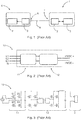
- FIG 1 a schematic illustration of such a known vehicle-to-vehicle charging situation is shown.
- a source electric vehicle 1 comprises an 11 kW bi-directional on-board charger 2 connected to an energy storage system 3, e.g.
- a load electric vehicle 4 comprises an 11 kW uni-directional on-board charger 5 connected to an energy storage system 6, e.g. a high voltage battery 6.
- the source electric vehicle 1 provides AC power at its AC inlet 7, which is transmitted to the AC inlet 8 of the load electric vehicle 4 via a charging cable 9.
- the load electric vehicle 4 may charge its energy storage system 6, similar to when the load electric vehicle 4 would be connected to a power grid via a charging station.
- the typical efficiency for known uni-directional on-board chargers and known bi-directional on-board chargers are around 94%.
- about 12% losses may occur, i.e. 6% from each on-board charger.
- the present disclosure proposes to provide a DC power to the AC inlet of the first electric vehicle and to bypass the on-board charger of the second electric vehicle such that the DC power of an insulated DC-DC converter of the first on-board charger may be directly provided to the energy storage system of the second electric vehicle.
- a DC power may be provided to the AC inlet of the first electric vehicle by controlling the bi-directional on-board charger of the first electric vehicle to provide DC power from the energy storage system of the first electric vehicle by switching the switches of a power factor correction unit of the bi-directional on-board charger of the first electric vehicle such that that at least a DC+ and a DC- line being provided at AC inlet of the first electric vehicle.
- the provide DC power bypasses the on-board charger of the second electric vehicle and the DC power provided by the first/source electric vehicle may charge a high voltage battery of the second electric vehicle.
- a higher overall charging system efficiency may be provided.
- the efficiency may remain at 94%, i.e. 6% higher than the efficiency in the conventional charging method.
- the step of controlling the bi-directional on-board charger of a first electric vehicle to provide a DC power from the energy storage system of the first electric vehicle at an electric vehicle inlet may comprise: controlling a charging current by the bi-directional on-board charger of the first electric vehicle.
- a data/control communication may be provided by means of a Powerline Communication (PLC) or CAN communication.
- PLC Powerline Communication
- the on-board charger of the first vehicle may control the charging current to the second/load electric vehicle by regulating the primary side of its isolated DC-DC converter, wherein the Powerline Communication protocol can be used to facilitate the charging between the electric vehicles.
- the charging current may be controlled by controlling an isolated DC-DC converter of the bi-directional on-board charger of a first electric vehicle.
- the on-board charger of the source electric vehicle may generate AC power which is fed to the load electric vehicle.
- the source vehicle may generate DC power using the same topology.
- the generated DC power may then fed to the load electric vehicle's high voltage battery directly, rather than having to pass through its on-board charger.
- the on-board charger of the source electric vehicle may control the charging current to the first electric vehicle by regulating the primary side its isolated DC-DC converter.
- the second electric vehicle may comprise a DC inlet, preferably being selected from: a CCS interface, a CHAdeMO interface and/or a GB/T interface. These interfaces comprise a DC inlet allowing to bypass the on-board charger of the second electric vehicle and directly provide the DC power to the energy storage system of the second electric vehicle.
- the bi-directional on-board charger may comprise at least one power factor correction unit and at least one isolated DC-DC converter.
- an electric vehicle which is configured to carry out a method described above, comprising: at least one bi-directional on-board charger comprising at least one power factor correction unit and at least one isolated DC-DC converter; the power factor correction unit comprising switches configured to be switched such that from the isolated DC-DC converter to the electric vehicle inlet at least a DC+ and a DC- line being provided.
- a use of an on-board charger comprising at least one power factor correction unit and at least one isolated DC-DC converter in an electric vehicle described above.
- a further aspect relates to a use of a charging cable for connecting two electric vehicles in a method described above.
- a further aspect relates to a control unit for controlling a bi-directional on-board charger of an electric vehicle to provide DC power from the energy storage system of the electric vehicle at an electric vehicle inlet configured to switch the switches of a power factor correction unit of the bi-directional on-board charger to provide at least a DC+ and a DC- line at the electric vehicle inlet of the electric vehicle.
- a further aspect relates to a computer program element which when executed by a processor is configured to carry out a method described above.
- a further aspect relates to a system for a vehicle-to-vehicle charging configured to carry out the method for charging vehicle-to-vehicle described above, comprising: a bi-directional on-board charger of a first electric vehicle; an energy storage system of the first electric vehicle; an energy storage system of a second electric vehicle; a control unit configured to control the bi-directional on-board charger of the first electric vehicle to provide a DC power from the energy storage system of the first electric vehicle at an electric vehicle inlet of the first electric vehicle; a charging cable configured to transfer the DC power to an electric vehicle inlet of a second electric vehicle; an on-board charger of the second electric vehicle configured to transfer the DC power from the electric vehicle inlet of the second electric vehicle directly to an energy storage system of the second electric vehicle.
- the control unit may be configured to control the charging of the energy storage system of the second electric vehicle.
- a further aspect relates to a method for vehicle-to-vehicle charging for electric vehicles, controlling a three phase bi-directional on-board charger of a first electric vehicle to provide a DC power from an energy storage system of the first electric vehicle at a first terminal L1 and a second terminal L2 of the three phase bi-directional on board-charger of the first electric vehicle; transferring the DC power from the first terminal L1 of the first electric vehicle to an energy storage system of the second electric vehicle, and from the second terminal L2 of the first electric vehicle to an energy storage system of the third electric vehicle.
- This may be advantageous as two electric vehicles (i.e. the second and the third electric vehicle) may be charged in parallel by one electric vehicle, i.e. the first vehicle.
- the second electric vehicle and the third electric vehicle are charged simultaneously.
- a voltage range of the energy storage system of the second electric vehicle and of the third electric vehicle is smaller than a voltage range of the energy system of the first electric vehicle.
- the voltage range of the energy storage system of the second electric vehicle and the voltage range of the energy storage system of the third electric vehicle are different.
- the first electric vehicle is connected to the second electric vehicle and to the third electric vehicle by means of one multi-port unit, wherein the multi-port unit comprises a common neutral conductor and wherein the multi-port unit is configured to provide a communication between the first electrical vehicle and the second electrical vehicle and the third electrical vehicle.
- communication means, as used herein, the exchange of data (e.g. control signal) and electric energy.
- the energy storage system of a fourth electrical vehicle is charged by the first electrical vehicle simultaneously to the second electrical vehicle and third electrical vehicle.
- a further aspect relates to a system for a vehicle-to-vehicle charging configured to carry out the method for charging vehicle-to-vehicle as described above, comprising: a three phase bi-directional on-board charger of a first electric vehicle; an energy storage system of the first electric vehicle; an energy storage system of a second electric vehicle; an energy storage system of a third electric vehicle; a multi-port unit configured to connect the three phase bi-directional on-board charger of the first electric vehicle and the energy storage system of the second electric vehicle and the energy storage system of a third electric vehicle; a control unit configured to control the three phase bi-directional on-board charger of the first electric vehicle to provide a DC power from the energy storage system of the first electric vehicle at a first terminal L1 and a second terminal L2 of the three phase bi-directional on board-charger of the first electric vehicle.
- a further aspect relates to a use of a multi-port unit in a method as described above or in a system as described above.
- a method for vehicle-to-vehicle charging for electric vehicles comprising: controlling a three phase bi-directional on-board charger of a first electric vehicle to provide a DC power from an energy storage system of the first electric vehicle at a first terminal L1 (40) of the three phase bi-directional on board-charger, transferring the DC power from the first terminal L1 (40) of the first electric vehicle to an energy storage system (34) of the second electric vehicle.
- the first electric vehicle has a 800V energy storage system and the second electric vehicle has a 400V energy storage system.
- the switches of the three phase bi-directional on board charger are switched such that the L2 and L3 phases are connected to L1.
- a DC-DC converter of the three phase bi-directional on-board charger may operate as a regulated 800V-400V DC-DC converter and may charge the energy storage system of the second vehicle.
- a L1 phase terminal and a neutral terminal may be connected to the DC+ and DC- terminal of the energy storage system of the second vehicle in order to charge the 400 Volt energy storage system.
- the three phase bi-directional on board charger is used as step-down converter here.
- FIG. 2 is a schematic view of a known bi-directional on-board charger 10 comprising a power factor correction (PFC) 11 and an isolated DC-DC converter 12 which can be used in both the first/source electric vehicle and the second/load electric vehicle.
- a known on-board charger has two stage power conversion. The first stage may be connected to AC power grid and is responsible for keeping the power factor close to unity while charging, also known as power factor correction (PFC) 11.
- the second stage is an isolated DC-DC converter 12, which may regulate the current and voltage in order to charge an energy storage system 3, e.g. a high-voltage (HV) battery 3, as shown in figure 1 . Apart from controlling the charging operation, the second stage also provides isolation from the AC input, and is typically implemented as a full bridge LLC resonator or phase shifted full bridge circuit.
- FIG. 3 is a schematic topology of the single-phase bi-directional on-board charger 10.
- the power stages for both uni-directional and bi-directional are principally the same, but in bi-directional operation a power factor correction 11 may generate either three phase or single phase AC voltages.
- the bi-directional on-board charger 10 may be equipped with active switches S1-S4 instead of diodes usually used in uni-directional on-board chargers.
- the on-board charger 10 inside the first/source electric vehicle generates AC power, which is fed to the second/load electric vehicle.
- the source vehicle generates DC power using the same topology by permanently closing the power factor correction 11 MOSFETs S1 and S4, or S2 and S3.
- the power factor correction 11 MOSFETs may be used as two wires to connect to the isolated DC-DC converter 12 primary side.
- the equivalent circuit after closing the MOSFETs S1 and S4 is shown in figure 4 .
- the switches S1 and S4 switch lines may act as DC+ and DC-, respectively.
- the on-board charger 10 may generate DC power but in the opposite polarity. Either of these combinations can be used.
- the generated DC power may then be fed to the second electric vehicle's HV battery directly, rather than having to pass through its on-board charger.
- the on-boards charger of the first vehicle may control the charging current to the first electric vehicle by regulating the primary side of its isolated DC-DC converter shown in figure 4 .
- a Powerline Communication or CAN communication may be used DC charging, and can be used to facilitate the charging between the electric vehicles. In this way, the electric power from the first vehicle will only pass through one on-board charger and thereby the power losses can be reduced to half.
- Such an implementation is compatible with both single and three phase configurations. If there are three phases, the AC side of the on-board charger may be reconfigured to single phase through the use of AC relays in order to transfer full power. There are no additional components or modules required in the shown implementation.
- the second electric vehicle may comprise a DC inlet, preferably being selected from: a CCS interface, a CHAdeMO interface and/or a GB/T interface. These interfaces comprise a DC inlet allowing to also bypass the on-board charger of the second electric vehicle and directly provide the DC power to the energy storage system of the second electric vehicle.
- the connector between the two electric vehicles comprises a Type 2/Type 1 interface to the source electric vehicle and a CCS DC/ CHAdeMO/ GBT DC interface to the load electric vehicle.
- the parties use a conventional Type 2/Type 1 charging cable, which usually comes standard with most electric vehicles.
- the DC power from source electric vehicle may transfer electric power through an on-board charger 20 of a load electric vehicle as shown in figure 5 .
- the load electric vehicle may still have either a uni-directional or a bi-directional on-board charger. If the load electric vehicle is using a known uni-directional diode rectifier 21, once the DC power is applied, the diodes D1 and D4 or D2 and D3 will conduct depends on the polarity of voltage.
- the power factor correct 22 MOSFETs may be turned off as the voltage on the load electric vehicle's input is already high enough to charge the energy storage system, e.g.
- the high voltage battery 23 and it can be fully regulated by the source electric vehicle's on-board charger, when used as shown in figure 4 .
- the power may flow through the isolated DC-DC converter 24 of the load electric vehicle to charge the high voltage battery 23 of the load electric vehicle.
- the load electric vehicle on-board charger 20 may be also used as DC-DC converter 24 but the overall charging efficiency is in practice just under 90%.
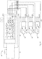
- FIG. 6 is a schematic view of a system 30 used in an embodiment of the present disclosure.
- the system is used for a vehicle-to-vehicle charging configured to carry out a method as described above.
- the system 30 comprises a three phase bi-directional on-board charger (32) of a first electric vehicle, an energy storage system (31) of the first electric vehicle, an energy storage system (34) of a second electric vehicle, an energy storage system (35) of a third electric vehicle, a multi-port unit (33) configured to connect the three phase bi-directional on-board charger (32) of the first electric vehicle and the energy storage system (34) of the second electric vehicle and the energy storage system (35) of a third electric vehicle, a control unit (51) configured to control the three phase bi-directional on-board charger (32) of the first electric vehicle to provide a DC power from the energy storage system (31) of the first electric vehicle at a first terminal L1 (40) and a second terminal L2 (41) of the three phase bi-directional on board-charger (32) of the first electric vehicle.
- the three phase bi-directional on board-charger (32) comprises further a third terminal L3 (42) and a neutral conduction terminal (43).
- the first terminal L1 (40), the second terminal L2 (41), the third terminal L3 (42) relate each to one of the phases L1, L2, L3 of the three phase on board charger (32).
- the first terminal L1 (40), the second terminal L2 (41), the third terminal L3 (42) are each connected to the multi-port unit (33).
- the multi-port unit (33) comprises a common neutral conductor (44), which is connected to the neutral conduction terminal (43).
- the multi-port unit (33) is configured to provide a communication between the first electric vehicle, the second electric vehicle, the third electric vehicle, and the fourth electric vehicle.
- the switches S1,S4 & inductor LA which operates as a step-down converter, are connected to L1.
- other two step-down DC-DC converters are formed by using S2,S5 & LB connected to L2 and the switches S3,S6 & LC connected to L3.
- These three step-down DC-DC's are independently capable of charging three vehicles with common return path through the neutral terminal.
- the relays R1 & R2 are switched such that L2 & L3 phases are independent from L1.
- the relay R3 is connected to the common source point of the switches S4,S5 & S6.
- the terminals L1,L2,L3 & Neutral are connected to the multi-port unit (33) from which three output ports are formed with a common neutral point for return current.
- the multi-port unit is connected to the DC+ & DC- (45, 46) of the second electric vehicle, to the DC+ & DC- (47, 48) of the third electric vehicle, and to the DC+ & DC- (49, 50) of the fourth electric vehicle in order to charge the energy storage system (34) of the second electric vehicle, the energy storage system (35) of the third electric vehicle, the energy storage system (36) of the fourth electric vehicle.
- This multi-port unit (33) is used to connect the three different electric vehicles at the same time to the first electric vehicle.
- the first electric vehicle can charge the three electric vehicles, which may have different voltages, which depends on state of charge of each electric vehicle.
- the communication between the first vehicle to other vehicles may also be taken care by multi-port unit (33).
- FIG. 7 is a schematic view of a three phase on board charger (62) of a first electric vehicle used to charge an energy storage system (63) of a second electric vehicle.
- the energy storage system (61) of the first electric vehicle has 800V.
- the energy storage system (63) of the second electric vehicle has 400V.
- the three-phase full bridge semiconductor switches S1, S2 & S3 are turned-ON and the relays R1 & R2 are switched such that L2 & L3 phases are connected to L1.
- the relay R3 is connected to mid-point of two capacitors. Each capacitor is rated for at least 500V.
- the DC-DC converter of three phase on-board charger inside first electric vehicle operates as a regulated 800V-400V DC-DC converter and charges the second electric vehicle, which is having 400V battery.
- the first vehicle L1 & Neutral terminals are connected to DC+ & DC- (64, 65) of the second electric vehicle in order to charge the 400V energy storage system (63).
- the main contactors 2 & 3, DC charging contactors 4 & 5 inside the second vehicle are turned ON to charge the 400V energy storage system (63).
- FIG 8 is another schematic view of a three phase on-board charger (72) of first vehicle used to charge a second electric vehicle.
- the three phase on-board charger does not support the full voltage range of the energy storage system of the second electric vehicle.
- the relays R1 & R2 are switched to connect to L1, relay R3 is switched to connect to the common source point of S4, S5 & S6.
- the switches S1, S4 & inductor L A together operated as a first step-down DC-DC converter.
- the switches S2, S5 & inductor L B together operated as a second step-down DC-DC converter and S3, S6 & inductor L C operated as a third step-down DC-DC converter.
- the three step-down converters are connected to L1, and there will be a 120 deg. phase shift angle between them to reduce the inductor current ripple.
- the three phase on-board charger of the first electric vehicle operates as a two stage DC-DC converter to charge the energy storage system (73) of the second electric vehicle with any voltage range window either it can be a 400V energy voltage system or a 800V energy storage voltage system as long as the actual energy storage system voltage of the second electric vehicle is always lower than actual energy storage system voltage of the first electric vehicle.
- the first electric vehicle L1 & Neutral terminals are connected to DC+ & DC-(74, 75) of the second electric vehicle in order to charge the 400V energy storage system (73).
- the first electric vehicle can also charge from a second electric vehicle.
- the switches S1, S4 & inductor L A operates as a first step-up DC-DC converter.
- the switches S2, S5 & inductor L B operates as a second step-up DC-DC converter and similarly the switches S3, S6 & inductor L C operates as a third step-up DC-DC converter.
- These three step-up DC-DC converters are having a 120 deg. phase shift to reduce the total current ripple.
- the present disclosure provides vehicle-to-vehicle charging with reduced losses resulting in a greater efficiency and lower charging times without the need of providing additional component.
Abstract
Description
- The present disclosure relates to a method for vehicle-to-vehicle charging of electric vehicles, an electric vehicle configured to carry out such a method, a use of a multiport unit in such an electric vehicle and a system for such a vehicle-to-vehicle charging.
- In the prior art, electric vehicles are well known comprising an electric train used to drive the electric vehicle. This electric drive train is supplied with energy by an electric energy storage system. From time to time, this energy storage system must be charged with electrical energy, which can be done, e.g., at home or a charging station where the electric vehicle can be connected to an electrical grid via a charging cable for AC charging, e.g., a
Type 2/Type 1 charging cable. For this purpose, an electric vehicle usually comprises an AC-DC on-board charger to allow charging of the energy storage system, e.g. Lithium-Ion batteries. To do this, the AC power is supplied to the on-board charger from the power grid and the on-board charger converts the AC power into a DC power that can be used to charge the energy storage system of the electric vehicle. - However, one of the main issues of this technology is still the limited range of electric vehicles, wherein a particular issue is considered to be the risk that the electric vehicle could run out of electric charge in a remote location where there is no access to a charging station. A possible solution to reduce this issue is to provide a vehicle-to-vehicle charging. Such a possibility allows an electric vehicle to charge another vehicle, typically via its on-board chargers. For this purpose, a possible source vehicle, the electric vehicle acting as an energy source, must comprise a bi-directional on-board charger that allows current to flow both into and out of the electric vehicle. Such an electric vehicle comprising a bi-directional on-board charger is able to supply AC power to the input/interface of the electric vehicle and, via a charging cable, may supply the load electric vehicle, the elective vehicle with an empty battery, with electricity. The on-board charger of the load electric vehicle can be either also a bi-directional or a unidirectional on-board charger.
- In view of this, it is found that a further need exists to improve a vehicle-to-vehicle charging. In particular there is a further need to increase the charging efficiency when charging from vehicle-to-vehicle.
- In the view of the above, it is an object of the present invention to provide a method and a system allowing an improved vehicle-to-vehicle charging. It is in particular an object of the present invention to provide an increased charging efficiency when charging from vehicle-to-vehicle.
- These and other objects, which become apparent upon reading the following description, are solved by the subject matter of the independent claims. The dependent claims refer to preferred embodiments of the invention.
- According to a first aspect, a method for vehicle-to-vehicle charging of electric vehicles may be provided, comprising the following steps: controlling a bi-directional on-board charger of a first electric vehicle to provide a DC power from an energy storage system of the first electric vehicle at an electric vehicle inlet of the first electric vehicle; transferring the DC power to an electric vehicle inlet of a second electric vehicle; transferring the DC power from the electric vehicle inlet of the second electric vehicle directly to an energy storage system of the second electric vehicle.
- The present disclosure is based on the finding that in a known vehicle-to-vehicle charging situation, the efficiency of such a charging is comparable low due to the losses when directing the charge through the on-board chargers of both electric vehicles in the intended way, i.e. converting the DC power of the energy storage system of the source electric vehicle into an AC power providing it to the AC inlet of the source electric inlet and converting the transmitted AC power in the load electric vehicle into a DC power for charging the energy storage system of the load electric vehicle. In
figure 1 , a schematic illustration of such a known vehicle-to-vehicle charging situation is shown. For example, in case a sourceelectric vehicle 1 comprises an 11 kW bi-directional on-board charger 2 connected to anenergy storage system 3, e.g. ahigh voltage battery 3, and a loadelectric vehicle 4 comprises an 11 kW uni-directional on-board charger 5 connected to anenergy storage system 6, e.g. ahigh voltage battery 6. The sourceelectric vehicle 1 provides AC power at itsAC inlet 7, which is transmitted to theAC inlet 8 of the loadelectric vehicle 4 via a charging cable 9. Thereby, the loadelectric vehicle 4 may charge itsenergy storage system 6, similar to when the loadelectric vehicle 4 would be connected to a power grid via a charging station. In praxis, the typical efficiency for known uni-directional on-board chargers and known bi-directional on-board chargers are around 94%. Thus, in such an example, the overall efficiency during this charging will be 0.94 x 0.94 = 0.883, i.e. 88.3%, wherein cable losses are negligible relative to the losses in the on-board chargers. As a result, in such a system about 12% losses may occur, i.e. 6% from each on-board charger. - In contrast to this known vehicle-to-vehicle charging, the present disclosure proposes to provide a DC power to the AC inlet of the first electric vehicle and to bypass the on-board charger of the second electric vehicle such that the DC power of an insulated DC-DC converter of the first on-board charger may be directly provided to the energy storage system of the second electric vehicle. In an example, a DC power may be provided to the AC inlet of the first electric vehicle by controlling the bi-directional on-board charger of the first electric vehicle to provide DC power from the energy storage system of the first electric vehicle by switching the switches of a power factor correction unit of the bi-directional on-board charger of the first electric vehicle such that that at least a DC+ and a DC- line being provided at AC inlet of the first electric vehicle. Thereby, it is possible that the provide DC power bypasses the on-board charger of the second electric vehicle and the DC power provided by the first/source electric vehicle may charge a high voltage battery of the second electric vehicle. Thereby a higher overall charging system efficiency may be provided. For example, in the above mentioned example, the efficiency may remain at 94%, i.e. 6% higher than the efficiency in the conventional charging method.
- In an implementation, the step of controlling the bi-directional on-board charger of a first electric vehicle to provide a DC power from the energy storage system of the first electric vehicle at an electric vehicle inlet may comprise: controlling a charging current by the bi-directional on-board charger of the first electric vehicle. In an example, a data/control communication may be provided by means of a Powerline Communication (PLC) or CAN communication. The on-board charger of the first vehicle may control the charging current to the second/load electric vehicle by regulating the primary side of its isolated DC-DC converter, wherein the Powerline Communication protocol can be used to facilitate the charging between the electric vehicles.
- In an implementation, the charging current may be controlled by controlling an isolated DC-DC converter of the bi-directional on-board charger of a first electric vehicle. In the known vehicle-to-vehicle charging, the on-board charger of the source electric vehicle may generate AC power which is fed to the load electric vehicle. However, in this implementation the source vehicle may generate DC power using the same topology. The generated DC power may then fed to the load electric vehicle's high voltage battery directly, rather than having to pass through its on-board charger. The on-board charger of the source electric vehicle may control the charging current to the first electric vehicle by regulating the primary side its isolated DC-DC converter.
- In an implementation, the second electric vehicle may comprise a DC inlet, preferably being selected from: a CCS interface, a CHAdeMO interface and/or a GB/T interface. These interfaces comprise a DC inlet allowing to bypass the on-board charger of the second electric vehicle and directly provide the DC power to the energy storage system of the second electric vehicle.
- In an implementation, the bi-directional on-board charger may comprise at least one power factor correction unit and at least one isolated DC-DC converter.
- According to a second aspect, an electric vehicle may be provided which is configured to carry out a method described above, comprising: at least one bi-directional on-board charger comprising at least one power factor correction unit and at least one isolated DC-DC converter; the power factor correction unit comprising switches configured to be switched such that from the isolated DC-DC converter to the electric vehicle inlet at least a DC+ and a DC- line being provided.
- According to a third aspect, a use of an on-board charger is proposed comprising at least one power factor correction unit and at least one isolated DC-DC converter in an electric vehicle described above. A further aspect relates to a use of a charging cable for connecting two electric vehicles in a method described above.
- A further aspect relates to a control unit for controlling a bi-directional on-board charger of an electric vehicle to provide DC power from the energy storage system of the electric vehicle at an electric vehicle inlet configured to switch the switches of a power factor correction unit of the bi-directional on-board charger to provide at least a DC+ and a DC- line at the electric vehicle inlet of the electric vehicle. A further aspect relates to a computer program element which when executed by a processor is configured to carry out a method described above.
- Moreover, a further aspect relates to a system for a vehicle-to-vehicle charging configured to carry out the method for charging vehicle-to-vehicle described above, comprising: a bi-directional on-board charger of a first electric vehicle; an energy storage system of the first electric vehicle; an energy storage system of a second electric vehicle; a control unit configured to control the bi-directional on-board charger of the first electric vehicle to provide a DC power from the energy storage system of the first electric vehicle at an electric vehicle inlet of the first electric vehicle; a charging cable configured to transfer the DC power to an electric vehicle inlet of a second electric vehicle; an on-board charger of the second electric vehicle configured to transfer the DC power from the electric vehicle inlet of the second electric vehicle directly to an energy storage system of the second electric vehicle. In an implementation of the system, the control unit may be configured to control the charging of the energy storage system of the second electric vehicle.
- A further aspect relates to a method for vehicle-to-vehicle charging for electric vehicles, controlling a three phase bi-directional on-board charger of a first electric vehicle to provide a DC power from an energy storage system of the first electric vehicle at a first terminal L1 and a second terminal L2 of the three phase bi-directional on board-charger of the first electric vehicle; transferring the DC power from the first terminal L1 of the first electric vehicle to an energy storage system of the second electric vehicle, and from the second terminal L2 of the first electric vehicle to an energy storage system of the third electric vehicle. This may be advantageous as two electric vehicles (i.e. the second and the third electric vehicle) may be charged in parallel by one electric vehicle, i.e. the first vehicle. In this aspect, all above explained explanations with respect to the electric vehicles, the specifics of the bi-directions on board charger of the first electric vehicle also apply here. In the following, only the specifics with respect to this aspect, i.e. a method for charging more than one vehicle by means of the first vehicle, are explained in more detail.
- In an implementation, the second electric vehicle and the third electric vehicle are charged simultaneously.
- In an implementation, a voltage range of the energy storage system of the second electric vehicle and of the third electric vehicle is smaller than a voltage range of the energy system of the first electric vehicle.
- In an implementation, the voltage range of the energy storage system of the second electric vehicle and the voltage range of the energy storage system of the third electric vehicle are different.
- In an implementation, the first electric vehicle is connected to the second electric vehicle and to the third electric vehicle by means of one multi-port unit, wherein the multi-port unit comprises a common neutral conductor and wherein the multi-port unit is configured to provide a communication between the first electrical vehicle and the second electrical vehicle and the third electrical vehicle. The term communication means, as used herein, the exchange of data (e.g. control signal) and electric energy.
- In an implementation, the energy storage system of a fourth electrical vehicle is charged by the first electrical vehicle simultaneously to the second electrical vehicle and third electrical vehicle.
- A further aspect relates to a system for a vehicle-to-vehicle charging configured to carry out the method for charging vehicle-to-vehicle as described above, comprising: a three phase bi-directional on-board charger of a first electric vehicle; an energy storage system of the first electric vehicle; an energy storage system of a second electric vehicle; an energy storage system of a third electric vehicle; a multi-port unit configured to connect the three phase bi-directional on-board charger of the first electric vehicle and the energy storage system of the second electric vehicle and the energy storage system of a third electric vehicle; a control unit configured to control the three phase bi-directional on-board charger of the first electric vehicle to provide a DC power from the energy storage system of the first electric vehicle at a first terminal L1 and a second terminal L2 of the three phase bi-directional on board-charger of the first electric vehicle.
- A further aspect relates to a use of a multi-port unit in a method as described above or in a system as described above.
- In another implementation, a method for vehicle-to-vehicle charging for electric vehicles is provided, comprising: controlling a three phase bi-directional on-board charger of a first electric vehicle to provide a DC power from an energy storage system of the first electric vehicle at a first terminal L1 (40) of the three phase bi-directional on board-charger, transferring the DC power from the first terminal L1 (40) of the first electric vehicle to an energy storage system (34) of the second electric vehicle. E.g. the first electric vehicle has a 800V energy storage system and the second electric vehicle has a 400V energy storage system. The switches of the three phase bi-directional on board charger are switched such that the L2 and L3 phases are connected to L1. A DC-DC converter of the three phase bi-directional on-board charger may operate as a regulated 800V-400V DC-DC converter and may charge the energy storage system of the second vehicle. A L1 phase terminal and a neutral terminal may be connected to the DC+ and DC- terminal of the energy storage system of the second vehicle in order to charge the 400 Volt energy storage system. In other words, the three phase bi-directional on board charger is used as step-down converter here.
- In the following, a non-exhaustive list of non-limiting examples is provided. Any one or more of the features of these examples may be combined with any one or more features of another example, embodiment, or aspect described herein.
- A. A method for vehicle-to-vehicle charging of electric vehicles (1, 4):
- controlling a bi-directional on-board charger (10) of a first electric vehicle (1) to provide a DC power from an energy storage system (3) of the first electric vehicle (1) at an electric vehicle inlet (7) of the first electric vehicle (1);
- transferring the DC power to an electric vehicle inlet (8) of a second electric vehicle (4);
- transferring the DC power from the electric vehicle inlet (8) of the second electric vehicle (4) to an energy storage system (6) of the second electric vehicle (4).
- B. Method according to claim A, controlling the bi-directional on-board charger (10) of the first electric vehicle (1) to provide DC power from the energy storage system (3) of the first electric vehicle (1) at an electric vehicle inlet (7) comprising:
switching the switches of a power factor correction unit (11) of the bi-directional on-board charger (10) of the first electric vehicle (1) such that at least a DC+ and a DC-line being provided at the electric vehicle inlet (7) of the first electric vehicle (1). - C. Method according to claim A or claim B, controlling the bi-directional on-board charger (10) of a first electric vehicle(1) to provide a DC power from the energy storage system (3) of the first electric vehicle (1) at an electric vehicle inlet (7) comprising:
controlling a charging current by the bi-directional on-board charger (10) of the first electric vehicle (1). - D. Method according to any one of the preceding claims, the charging current being controlled by controlling an isolated DC-DC converter (12) of the bi-directional on-board charger (10) of a first electric vehicle (1).
- E. Method according to any one of the preceding claims, a data communication being provided by means of a Powerline Communication (PLC) or CAN communication.
- F. Method according to any one of the preceding claims, the second electric vehicle (4) comprising a DC-inlet, preferably being selected from the following: a CCS interface, a CHAdeMO interface and/or a GB/T interface.
- G. Method according to any one of the preceding claims, the DC power bypassing an on-board charger (5) of the second electric vehicle (4).
- H. Method according to any one of the preceding claims, the bi-directional on-board charger (10) of the first electric vehicle (1) comprising at least one power factor correction unit (11) and at least one isolated DC-DC converter (12).
- I. Electric vehicle (1) configured to carry out a method according to any one of the preceding claims, comprising:
- at least one bi-directional on-board charger (10) comprising at least one power factor correction unit (11) and at least one isolated DC-DC converter (12);
- the power facto correction unit (11) comprising switches (S1-S4) configured to be switched such that at least a DC+ and a DC- line being provided from the isolated DC-DC converter (12) to the electric vehicle inlet (7) of the electric vehicle.
- J. Use of an on-board charger (10) comprising at least one power factor correction unit (11) and at least one isolated DC-DC converter (12) in an electric vehicle (1) according to claim I.
- K. Use of a charging cable (9) for connecting two electric vehicles (1, 4) in a method according to any one of claims A to H.
- L. Control unit for controlling a bi-directional on-board charger (10) of an electric vehicle (1) to provide DC power from a energy storage system (3) of the electric vehicle (1) at an electric vehicle inlet (7) being configured to switch switches (S1-S4) of a power factor correction unit (11) of the bi-directional on-board charger (10) to provide at least a DC+ and a DC- line at the electric vehicle inlet (7) of the electric vehicle (1).
- M. A computer program element which when executed by a processor being configured to carry out a method according to any one of claims A to H.
- N. A system for a vehicle-to-vehicle charging configured to carry out the method for charging vehicle-to-vehicle according to any one of claims A to H, comprising:
- a bi-directional on-board charger (10) of a first electric vehicle (1);
- an energy storage system (3) of the first electric vehicle (1);
- an energy storage system (6) of a second electric vehicle (4);
- a control unit configured to control the bi-directional on-board charger (10) of the first electric vehicle (1) to provide a DC power from the energy storage system (3) of the first electric vehicle (1) at an electric vehicle inlet (7) of the first electric vehicle (1);
- a charging cable (9) configured to transfer the DC power to an electric vehicle inlet (8) of the second electric vehicle (4);
- an on-board charger (20) of the second electric vehicle (4) configured to transfer the DC power from the electric vehicle inlet (8) of the second electric vehicle (4) directly to an energy storage system (6) of the second electric vehicle (4).
- O. System according to claim N, the control unit being configured to control the charging of the energy storage system (6) of the second electric vehicle (4).
- In the following, the disclosure is described exemplarily with reference to the enclosed figure, in which
- Figure 1
- is a schematic view of known vehicle-to-vehicle charging through the on-board chargers of a load electric vehicle and a source electric vehicle;
- Figure 2
- is a schematic view of a known bi-directional on-board charger comprising a power factor correction and an isolated DC-DC converter;
- Figure 3
- is a schematic topology of a single-phase bi-directional on-board charger;
- Figure 4
- is a schematic view of an on-board charger of a source electric vehicle used in an embodiment of to the present disclosure;
- Figure 5
- is a schematic view an on-board charger of a load electric vehicle used in an embodiment of the present disclosure;
- Figure 6
- is a schematic view of a system used in an embodiment of the present disclosure;
- Figure 7
- is a schematic view of a three phase on board charger of a first electric vehicle used to charge a second electric vehicle; and
- Figure 8
- is another schematic view of a three phase on board charger of first vehicle used to charge a second electric vehicle.
- Notably, the figures are merely schematic representations and serve only to illustrate an embodiment of the present disclosure. Identical or equivalent elements are in principle provided with the same reference signs.
-
Figures 2 is a schematic view of a known bi-directional on-board charger 10 comprising a power factor correction (PFC) 11 and an isolated DC-DC converter 12 which can be used in both the first/source electric vehicle and the second/load electric vehicle. A known on-board charger has two stage power conversion. The first stage may be connected to AC power grid and is responsible for keeping the power factor close to unity while charging, also known as power factor correction (PFC) 11. The second stage is an isolated DC-DC converter 12, which may regulate the current and voltage in order to charge anenergy storage system 3, e.g. a high-voltage (HV)battery 3, as shown infigure 1 . Apart from controlling the charging operation, the second stage also provides isolation from the AC input, and is typically implemented as a full bridge LLC resonator or phase shifted full bridge circuit. -
Figure 3 is a schematic topology of the single-phase bi-directional on-board charger 10. The power stages for both uni-directional and bi-directional are principally the same, but in bi-directional operation apower factor correction 11 may generate either three phase or single phase AC voltages. To achieve bi-directionality from the same power stages, the bi-directional on-board charger 10 may be equipped with active switches S1-S4 instead of diodes usually used in uni-directional on-board chargers. - In known vehicle-to-vehicle charging, the on-
board charger 10 inside the first/source electric vehicle generates AC power, which is fed to the second/load electric vehicle. However, in the shown embodiment, it is proposed that the source vehicle generates DC power using the same topology by permanently closing thepower factor correction 11 MOSFETs S1 and S4, or S2 and S3. Thereby, thepower factor correction 11 MOSFETs may be used as two wires to connect to the isolated DC-DC converter 12 primary side. The equivalent circuit after closing the MOSFETs S1 and S4 is shown infigure 4 . Now the switches S1 and S4 switch lines may act as DC+ and DC-, respectively. Similarly by closing the MOSFETs S2 and S3 and opening S1 and S4, the on-board charger 10 may generate DC power but in the opposite polarity. Either of these combinations can be used. - The generated DC power may then be fed to the second electric vehicle's HV battery directly, rather than having to pass through its on-board charger. The on-boards charger of the first vehicle may control the charging current to the first electric vehicle by regulating the primary side of its isolated DC-DC converter shown in
figure 4 . In this respect, a Powerline Communication or CAN communication may be used DC charging, and can be used to facilitate the charging between the electric vehicles. In this way, the electric power from the first vehicle will only pass through one on-board charger and thereby the power losses can be reduced to half. Such an implementation is compatible with both single and three phase configurations. If there are three phases, the AC side of the on-board charger may be reconfigured to single phase through the use of AC relays in order to transfer full power. There are no additional components or modules required in the shown implementation. - In an implementation, the second electric vehicle may comprise a DC inlet, preferably being selected from: a CCS interface, a CHAdeMO interface and/or a GB/T interface. These interfaces comprise a DC inlet allowing to also bypass the on-board charger of the second electric vehicle and directly provide the DC power to the energy storage system of the second electric vehicle. In this respect, it is preferred that the connector between the two electric vehicles comprises a
Type 2/Type 1 interface to the source electric vehicle and a CCS DC/ CHAdeMO/ GBT DC interface to the load electric vehicle. - However, it is also possible that the parties use a
conventional Type 2/Type 1 charging cable, which usually comes standard with most electric vehicles. In such a situation, the DC power from source electric vehicle may transfer electric power through an on-board charger 20 of a load electric vehicle as shown infigure 5 . The load electric vehicle may still have either a uni-directional or a bi-directional on-board charger. If the load electric vehicle is using a knownuni-directional diode rectifier 21, once the DC power is applied, the diodes D1 and D4 or D2 and D3 will conduct depends on the polarity of voltage. The power factor correct 22 MOSFETs may be turned off as the voltage on the load electric vehicle's input is already high enough to charge the energy storage system, e.g. thehigh voltage battery 23 and it can be fully regulated by the source electric vehicle's on-board charger, when used as shown infigure 4 . After thepower factor corrector 22 capacitor, the power may flow through the isolated DC-DC converter 24 of the load electric vehicle to charge thehigh voltage battery 23 of the load electric vehicle. In such a way, the load electric vehicle on-board charger 20 may be also used as DC-DC converter 24 but the overall charging efficiency is in practice just under 90%. -
Figure 6 is a schematic view of asystem 30 used in an embodiment of the present disclosure. The system is used for a vehicle-to-vehicle charging configured to carry out a method as described above. Thesystem 30 comprises a three phase bi-directional on-board charger (32) of a first electric vehicle, an energy storage system (31) of the first electric vehicle, an energy storage system (34) of a second electric vehicle, an energy storage system (35) of a third electric vehicle, a multi-port unit (33) configured to connect the three phase bi-directional on-board charger (32) of the first electric vehicle and the energy storage system (34) of the second electric vehicle and the energy storage system (35) of a third electric vehicle, a control unit (51) configured to control the three phase bi-directional on-board charger (32) of the first electric vehicle to provide a DC power from the energy storage system (31) of the first electric vehicle at a first terminal L1 (40) and a second terminal L2 (41) of the three phase bi-directional on board-charger (32) of the first electric vehicle. The three phase bi-directional on board-charger (32) comprises further a third terminal L3 (42) and a neutral conduction terminal (43). The first terminal L1 (40), the second terminal L2 (41), the third terminal L3 (42) relate each to one of the phases L1, L2, L3 of the three phase on board charger (32). The first terminal L1 (40), the second terminal L2 (41), the third terminal L3 (42) are each connected to the multi-port unit (33). The multi-port unit (33) comprises a common neutral conductor (44), which is connected to the neutral conduction terminal (43). The multi-port unit (33) is configured to provide a communication between the first electric vehicle, the second electric vehicle, the third electric vehicle, and the fourth electric vehicle. To charge the second energy storage system (34), the third energy storage system (35), and the fourth energy storage system (36), the following switch process in the three phase on board charger (32) is carried out. The switches S1,S4 & inductor LA, which operates as a step-down converter, are connected to L1. Similarly, other two step-down DC-DC converters are formed by using S2,S5 & LB connected to L2 and the switches S3,S6 & LC connected to L3. These three step-down DC-DC's are independently capable of charging three vehicles with common return path through the neutral terminal. The relays R1 & R2 are switched such that L2 & L3 phases are independent from L1. The relay R3 is connected to the common source point of the switches S4,S5 & S6. The terminals L1,L2,L3 & Neutral are connected to the multi-port unit (33) from which three output ports are formed with a common neutral point for return current. The multi-port unit is connected to the DC+ & DC- (45, 46) of the second electric vehicle, to the DC+ & DC- (47, 48) of the third electric vehicle, and to the DC+ & DC- (49, 50) of the fourth electric vehicle in order to charge the energy storage system (34) of the second electric vehicle, the energy storage system (35) of the third electric vehicle, the energy storage system (36) of the fourth electric vehicle. This multi-port unit (33) is used to connect the three different electric vehicles at the same time to the first electric vehicle. The first electric vehicle can charge the three electric vehicles, which may have different voltages, which depends on state of charge of each electric vehicle. The communication between the first vehicle to other vehicles may also be taken care by multi-port unit (33). -
Figure 7 is a schematic view of a three phase on board charger (62) of a first electric vehicle used to charge an energy storage system (63) of a second electric vehicle. The energy storage system (61) of the first electric vehicle has 800V. The energy storage system (63) of the second electric vehicle has 400V. The three-phase full bridge semiconductor switches S1, S2 & S3 are turned-ON and the relays R1 & R2 are switched such that L2 & L3 phases are connected to L1. The relay R3 is connected to mid-point of two capacitors. Each capacitor is rated for at least 500V. In this case, the DC-DC converter of three phase on-board charger inside first electric vehicle operates as a regulated 800V-400V DC-DC converter and charges the second electric vehicle, which is having 400V battery. The first vehicle L1 & Neutral terminals are connected to DC+ & DC- (64, 65) of the second electric vehicle in order to charge the 400V energy storage system (63). Themain contactors 2 & 3,DC charging contactors 4 & 5 inside the second vehicle are turned ON to charge the 400V energy storage system (63). -
Figure 8 is another schematic view of a three phase on-board charger (72) of first vehicle used to charge a second electric vehicle. In comparison to the description presented inFigure 7 , the three phase on-board charger does not support the full voltage range of the energy storage system of the second electric vehicle. For this operation, the relays R1 & R2 are switched to connect to L1, relay R3 is switched to connect to the common source point of S4, S5 & S6. The switches S1, S4 & inductor LA together operated as a first step-down DC-DC converter. The switches S2, S5 & inductor LB together operated as a second step-down DC-DC converter and S3, S6 & inductor LC operated as a third step-down DC-DC converter. These three step-down converters are connected to L1, and there will be a 120 deg. phase shift angle between them to reduce the inductor current ripple. The three phase on-board charger of the first electric vehicle operates as a two stage DC-DC converter to charge the energy storage system (73) of the second electric vehicle with any voltage range window either it can be a 400V energy voltage system or a 800V energy storage voltage system as long as the actual energy storage system voltage of the second electric vehicle is always lower than actual energy storage system voltage of the first electric vehicle. The first electric vehicle L1 & Neutral terminals are connected to DC+ & DC-(74, 75) of the second electric vehicle in order to charge the 400V energy storage system (73). The first electric vehicle can also charge from a second electric vehicle. In this case, the switches S1, S4 & inductor LA operates as a first step-up DC-DC converter. The switches S2, S5 & inductor LB operates as a second step-up DC-DC converter and similarly the switches S3, S6 & inductor LC operates as a third step-up DC-DC converter. These three step-up DC-DC converters are having a 120 deg. phase shift to reduce the total current ripple. - As a result, the present disclosure provides vehicle-to-vehicle charging with reduced losses resulting in a greater efficiency and lower charging times without the need of providing additional component. This is because, it is possible, e.g. by means of switching/controlling the switches of the power factor correction of the on-board charger of the first/source electric vehicle, that the DC power of the isolated DC-DC converter can be provided to the AC inlet of the first electric vehicle and then transmitted to the AC inlet of the second/load electric vehicle from which it can be directly provided to the energy storage system of the second electric vehicle.
- Other variations to the disclosed embodiment can be understood and effected by those skilled in the art in practicing the claimed subject matter, from the study of the drawings, the disclosure, and the appended claims. In the claims, the word "comprising" does not exclude other elements or steps and the indefinite article "a" or "an" does not exclude a plurality. The mere fact that certain measures are recited in mutually different dependent claims does not indicate that a combination of these measures cannot be used to advantage. Any reference signs in the claims should not be construed as limiting the scope of the claims.
-
- 1
- source electric vehicle
- 2
- bi-directional on-board charger of a source electric vehicle
- 3
- energy storage system/high voltage battery
- 4
- load electric vehicle
- 5
- uni- or bi-directional on-board charger of a load electric vehicle
- 6
- energy storage system/high voltage battery
- 7
- AC inlet source electric vehicle
- 8
- AC inlet load electric vehicle
- 9
- charging cable
- 10
- bi-directional on-board charger of a source electric vehicle
- 11
- power factor correction (PFC)
- 12
- isolated DC-DC converter
- 20
- uni- or bi-directional on-board charger of a load electric vehicle
- 21
- uni-directional diode rectifier
- 22
- power factor correction (PFC)
- 23
- energy storage system/high voltage battery
- 24
- isolated DC-DC converter
- 30
- system
- 31
- energy storage system of a first electric vehicle
- 32, 62, 72
- three phase bi-directional on-board charger of a first electric vehicle
- 33
- multi-port unit
- 34, 63, 73
- energy storage system of a second electric vehicle
- 35
- energy storage system of a third electric vehicle
- 36
- energy storage system of a fourth electric vehicle
- 40,41,42
- L1, L2, L3 terminals
- 43
- neutral conduction terminal
- 44
- common neutral conductor
- 45 to 50
- DC terminals
- 51
- control unit
- 64, 65, 74, 75
- DC terminals
Claims (15)
- A method for vehicle-to-vehicle charging for electric vehicles,controlling a three phase bi-directional on-board charger (32) of a first electric vehicle to provide a DC power from an energy storage system (31) of the first electric vehicle at a first terminal L1 (40) and a second terminal L2 (41) of the three phase bi-directional on board-charger (32) of the first electric vehicle;transferring the DC power from the first terminal L1 (40) of the first electric vehicle to an energy storage system (34) of a second electric vehicle, and from the second terminal L2 (41) of the first electric vehicle to an energy storage system (35) of a third electric vehicle.
- The method according to claim 1, wherein the second electric vehicle and the third electric vehicle are charged simultaneously.
- The method according to claim 1 or claim 2, wherein a voltage range of the energy storage system (34) of the second electric vehicle and of the energy storage system (35) of the third electric vehicle is smaller than a voltage range of the energy system (31) of the first electric vehicle.
- The method according to any one of the preceding claims, wherein the voltage range of the energy storage system (34) of the second electric vehicle and the voltage range of the energy storage system (35) of the third electric vehicle are different.
- Method according to any one of the preceding claims, the charging current being controlled by controlling an isolated DC-DC converter of the bi-directional on-board charger (32) of a first electric vehicle.
- Method according to any one of the preceding claims, a data communication being provided by means of a Powerline Communication (PLC) or CAN communication.
- Method according to any one of the preceding claims, the second and/or third electric vehicle comprising a DC-inlet, preferably being selected from the following: a CCS interface, a CHAdeMO interface and/or a GB/T interface.
- Method according to any one of the preceding claims, the DC power bypassing an on-board charger of the second electric vehicle.
- Method according to any one of the preceding claims, the bi-directional on-board charger of the first electric vehicle comprising at least one power factor correction unit and at least one isolated DC-DC converter.
- The method according to any one of the preceding claims, wherein the first electric vehicle is connected to the second electric vehicle and to the third electric vehicle by means of one multi-port unit (33), wherein the multi-port unit comprises a common neutral conductor (44) and wherein the multi-port unit is configured to provide a communication between the first electrical vehicle and the second electrical vehicle and the third electrical vehicle.
- The method according to any one of the preceding claims, wherein the energy storage system (36) of a fourth electric vehicle is charged by the first electric vehicle simultaneously to the second electric vehicle and third electric vehicle.
- A computer program element which when executed by a processor being configured to carry out a method according to any one of claims 1 to 11.
- Electric vehicle (1) configured to carry out a method according to any one of the claims 1 to 11, comprising:
a three phase bi-directional on-board charger (32) configured to provide a DC power from an energy storage system (31) of the electric vehicle at a first terminal L1 (40) and a second terminal L2 (41) of the three phase bi-directional on board-charger (32) of electric vehicle. - A system for a vehicle-to-vehicle charging configured to carry out the method for charging vehicle-to-vehicle according to any one of claims 1 to 11, comprising:a three phase bi-directional on-board charger (32) of a first electric vehicle;an energy storage system (31) of the first electric vehicle;an energy storage system (34) of a second electric vehicle;an energy storage system (35) of a third electric vehicle;a multi-port unit (33) configured to connect the three phase bi-directional on-board charger (32) of the first electric vehicle and the energy storage system (34) of the second electric vehicle and the energy storage system (35) of a third electric vehicle;a control unit (44) configured to control the three phase bi-directional on-board charger (32) of the first electric vehicle to provide a DC power from the energy storage system (31) of the first electric vehicle at a first terminal L1 (40) and a second terminal L2 (41) of the three phase bi-directional on board-charger (32) of the first electric vehicle.
- Use of a multi-port unit in a method according to any one of the claims 1 to 11 or in a system according to claim 14.
Priority Applications (2)
| Application Number | Priority Date | Filing Date | Title |
|---|---|---|---|
| US17/739,297 US20220379744A1 (en) | 2020-05-28 | 2022-05-09 | Method and system for vehicle-to-vehicle charging of electric vehicles |
| CN202210577841.3A CN115384327A (en) | 2020-05-28 | 2022-05-25 | Vehicle-to-vehicle charging method and system for electric vehicle |
Applications Claiming Priority (1)
| Application Number | Priority Date | Filing Date | Title |
|---|---|---|---|
| EP20177100.3A EP3915824A1 (en) | 2020-05-28 | 2020-05-28 | Method and system for vehicle-to-vehicle charging of electric vehicles |
Publications (1)
| Publication Number | Publication Date |
|---|---|
| EP3915826A1 true EP3915826A1 (en) | 2021-12-01 |
Family
ID=70918325
Family Applications (2)
| Application Number | Title | Priority Date | Filing Date |
|---|---|---|---|
| EP20177100.3A Withdrawn EP3915824A1 (en) | 2020-05-28 | 2020-05-28 | Method and system for vehicle-to-vehicle charging of electric vehicles |
| EP21175654.9A Pending EP3915826A1 (en) | 2020-05-28 | 2021-05-25 | Method and system for vehicle-to-vehicle charging of electric vehicles |
Family Applications Before (1)
| Application Number | Title | Priority Date | Filing Date |
|---|---|---|---|
| EP20177100.3A Withdrawn EP3915824A1 (en) | 2020-05-28 | 2020-05-28 | Method and system for vehicle-to-vehicle charging of electric vehicles |
Country Status (3)
| Country | Link |
|---|---|
| US (1) | US20220379744A1 (en) |
| EP (2) | EP3915824A1 (en) |
| CN (1) | CN115384327A (en) |
Cited By (1)
| Publication number | Priority date | Publication date | Assignee | Title |
|---|---|---|---|---|
| CN114336707A (en) * | 2021-12-29 | 2022-04-12 | 中汽研新能源汽车检验中心(天津)有限公司 | Operation system of alternating current V2V charge-discharge technology |
Families Citing this family (1)
| Publication number | Priority date | Publication date | Assignee | Title |
|---|---|---|---|---|
| DE202022103449U1 (en) | 2022-06-21 | 2022-06-28 | Madhu Gopahanal Manjunath | Portable EV to EV charger |
Citations (5)
| Publication number | Priority date | Publication date | Assignee | Title |
|---|---|---|---|---|
| WO2013009178A2 (en) * | 2011-07-11 | 2013-01-17 | Abb B.V. | Method and device for determining the charging behaviour of electric vehicles and a charging system incorporating such a method |
| US20130020993A1 (en) * | 2011-07-18 | 2013-01-24 | Green Charge Networks Llc | Multi-Mode Electric Vehicle Charging Station |
| US20160079776A1 (en) * | 2013-06-03 | 2016-03-17 | Panasonic Intellectual Property Management Co., Ltd. | Charge/discharge device |
| US20160368390A1 (en) * | 2013-06-28 | 2016-12-22 | Byd Company Limited | Vehicle mutual-charging system and charging connector |
| WO2019026095A1 (en) * | 2017-08-03 | 2019-02-07 | Green Arrow Power S.R.L. | A mobile charging unit, particularly for electric vehicles, and a management system thereof for the delivery of charges on request |
Family Cites Families (1)
| Publication number | Priority date | Publication date | Assignee | Title |
|---|---|---|---|---|
| JP2013236490A (en) * | 2012-05-09 | 2013-11-21 | Nippon Tekumo:Kk | Dc charging method of electric car |
-
2020
- 2020-05-28 EP EP20177100.3A patent/EP3915824A1/en not_active Withdrawn
-
2021
- 2021-05-25 EP EP21175654.9A patent/EP3915826A1/en active Pending
-
2022
- 2022-05-09 US US17/739,297 patent/US20220379744A1/en active Pending
- 2022-05-25 CN CN202210577841.3A patent/CN115384327A/en active Pending
Patent Citations (5)
| Publication number | Priority date | Publication date | Assignee | Title |
|---|---|---|---|---|
| WO2013009178A2 (en) * | 2011-07-11 | 2013-01-17 | Abb B.V. | Method and device for determining the charging behaviour of electric vehicles and a charging system incorporating such a method |
| US20130020993A1 (en) * | 2011-07-18 | 2013-01-24 | Green Charge Networks Llc | Multi-Mode Electric Vehicle Charging Station |
| US20160079776A1 (en) * | 2013-06-03 | 2016-03-17 | Panasonic Intellectual Property Management Co., Ltd. | Charge/discharge device |
| US20160368390A1 (en) * | 2013-06-28 | 2016-12-22 | Byd Company Limited | Vehicle mutual-charging system and charging connector |
| WO2019026095A1 (en) * | 2017-08-03 | 2019-02-07 | Green Arrow Power S.R.L. | A mobile charging unit, particularly for electric vehicles, and a management system thereof for the delivery of charges on request |
Non-Patent Citations (1)
| Title |
|---|
| ANONYMOUS: "Vehicle Electrification: Technologies, Challenges, and a Global Perspective for Smart Grids | IntechOpen", 27 November 2019 (2019-11-27), XP055746629, Retrieved from the Internet <URL:https://www.intechopen.com/books/innovation-in-energy-systems-new-technologies-for-changing-paradigms/vehicle-electrification-technologies-challenges-and-a-global-perspective-for-smart-grids> [retrieved on 20201103] * |
Cited By (2)
| Publication number | Priority date | Publication date | Assignee | Title |
|---|---|---|---|---|
| CN114336707A (en) * | 2021-12-29 | 2022-04-12 | 中汽研新能源汽车检验中心(天津)有限公司 | Operation system of alternating current V2V charge-discharge technology |
| CN114336707B (en) * | 2021-12-29 | 2024-01-19 | 中汽研新能源汽车检验中心(天津)有限公司 | Operation system of alternating current V2V charge-discharge technology |
Also Published As
| Publication number | Publication date |
|---|---|
| CN115384327A (en) | 2022-11-25 |
| US20220379744A1 (en) | 2022-12-01 |
| EP3915824A1 (en) | 2021-12-01 |
Similar Documents
| Publication | Publication Date | Title |
|---|---|---|
| US10917023B2 (en) | Power conversion system and method for pre charging DC-Bus capacitors therein | |
| US20220402390A1 (en) | A multimodal converter for interfacing with multiple energy sources | |
| US10498221B2 (en) | Multi-mode energy router | |
| KR20190085530A (en) | Method for controlling an onboard charging device of an electric or hybrid vehicle | |
| EP2815913A1 (en) | Recharging system for electric vehicles | |
| US20220379744A1 (en) | Method and system for vehicle-to-vehicle charging of electric vehicles | |
| WO2018202462A1 (en) | Electric charging system and method | |
| CN109874385B (en) | Power conversion system | |
| CN101997324A (en) | Systems and methods for bi-directional energy delivery with galvanic isolation | |
| KR20200115785A (en) | Bi-directional on board charger and a method for controlling thereof | |
| US11496053B2 (en) | Power conversion system with dc-bus pre-charge | |
| CN105659488A (en) | Charging circuit for an energy storage device and method for charging an energy storage device | |
| US9768617B2 (en) | Power management system comprising a power source, a source of renewable energy, and a power converter | |
| KR20210062670A (en) | Charging circuit for vehicle-side stored electric energy source | |
| CN115362610B (en) | SST system with multiple LVDC outputs | |
| KR102202495B1 (en) | Controller for charging battery in vehicle and operating method thereof | |
| CN111106667B (en) | Power supply device and power supply system | |
| CN104269910A (en) | Charging device | |
| US20230143719A1 (en) | Vehicle Power Conversion System and Method | |
| US11888389B1 (en) | Variable-phase power converter | |
| KR102379157B1 (en) | Integrated dc/dc and ac/dc converter system | |
| US11970067B2 (en) | Constant current fast charging of electric vehicles via DC grid using dual inverter drive | |
| EP3985821A1 (en) | Power grid | |
| US20210146792A1 (en) | Constant current fast charging of electric vehicles via dc grid using dual inverter drive | |
| JP2019088087A (en) | Power converter |
Legal Events
| Date | Code | Title | Description |
|---|---|---|---|
| PUAI | Public reference made under article 153(3) epc to a published international application that has entered the european phase |
Free format text: ORIGINAL CODE: 0009012 |
|
| STAA | Information on the status of an ep patent application or granted ep patent |
Free format text: STATUS: THE APPLICATION HAS BEEN PUBLISHED |
|
| AK | Designated contracting states |
Kind code of ref document: A1 Designated state(s): AL AT BE BG CH CY CZ DE DK EE ES FI FR GB GR HR HU IE IS IT LI LT LU LV MC MK MT NL NO PL PT RO RS SE SI SK SM TR |
|
| B565 | Issuance of search results under rule 164(2) epc |
Effective date: 20211022 |
|
| STAA | Information on the status of an ep patent application or granted ep patent |
Free format text: STATUS: REQUEST FOR EXAMINATION WAS MADE |
|
| 17P | Request for examination filed |
Effective date: 20220503 |
|
| RBV | Designated contracting states (corrected) |
Designated state(s): AL AT BE BG CH CY CZ DE DK EE ES FI FR GB GR HR HU IE IS IT LI LT LU LV MC MK MT NL NO PL PT RO RS SE SI SK SM TR |
|
| STAA | Information on the status of an ep patent application or granted ep patent |
Free format text: STATUS: EXAMINATION IS IN PROGRESS |
|
| 17Q | First examination report despatched |
Effective date: 20230711 |
|
| GRAP | Despatch of communication of intention to grant a patent |
Free format text: ORIGINAL CODE: EPIDOSNIGR1 |
|
| STAA | Information on the status of an ep patent application or granted ep patent |
Free format text: STATUS: GRANT OF PATENT IS INTENDED |