EP3915825B1 - Modular charging column for electric dc loading of a battery of an electric vehicle - Google Patents
Modular charging column for electric dc loading of a battery of an electric vehicle Download PDFInfo
- Publication number
- EP3915825B1 EP3915825B1 EP21174892.6A EP21174892A EP3915825B1 EP 3915825 B1 EP3915825 B1 EP 3915825B1 EP 21174892 A EP21174892 A EP 21174892A EP 3915825 B1 EP3915825 B1 EP 3915825B1
- Authority
- EP
- European Patent Office
- Prior art keywords
- charging
- electrical energy
- self
- sufficient
- module
- Prior art date
- Legal status (The legal status is an assumption and is not a legal conclusion. Google has not performed a legal analysis and makes no representation as to the accuracy of the status listed.)
- Active
Links
- 238000003860 storage Methods 0.000 claims description 56
- 238000004146 energy storage Methods 0.000 claims description 41
- 238000006243 chemical reaction Methods 0.000 claims description 15
- 238000007599 discharging Methods 0.000 claims description 6
- 238000010276 construction Methods 0.000 claims description 2
- 230000005611 electricity Effects 0.000 description 10
- 238000012937 correction Methods 0.000 description 7
- 238000002955 isolation Methods 0.000 description 7
- 230000002457 bidirectional effect Effects 0.000 description 4
- 230000032683 aging Effects 0.000 description 3
- 238000011161 development Methods 0.000 description 3
- 230000018109 developmental process Effects 0.000 description 3
- 238000000034 method Methods 0.000 description 3
- 230000005855 radiation Effects 0.000 description 3
- 238000013461 design Methods 0.000 description 2
- 238000009434 installation Methods 0.000 description 2
- 238000004519 manufacturing process Methods 0.000 description 2
- 238000012544 monitoring process Methods 0.000 description 2
- 238000013021 overheating Methods 0.000 description 2
- 230000008092 positive effect Effects 0.000 description 2
- 230000001681 protective effect Effects 0.000 description 2
- 238000011144 upstream manufacturing Methods 0.000 description 2
- 206010014357 Electric shock Diseases 0.000 description 1
- 230000015556 catabolic process Effects 0.000 description 1
- 239000004020 conductor Substances 0.000 description 1
- 230000006378 damage Effects 0.000 description 1
- 230000002950 deficient Effects 0.000 description 1
- 230000001419 dependent effect Effects 0.000 description 1
- 238000005516 engineering process Methods 0.000 description 1
- 238000004880 explosion Methods 0.000 description 1
- 238000009413 insulation Methods 0.000 description 1
- 230000010354 integration Effects 0.000 description 1
- 238000012432 intermediate storage Methods 0.000 description 1
- 230000007935 neutral effect Effects 0.000 description 1
Images

Classifications
-
- B—PERFORMING OPERATIONS; TRANSPORTING
- B60—VEHICLES IN GENERAL
- B60L—PROPULSION OF ELECTRICALLY-PROPELLED VEHICLES; SUPPLYING ELECTRIC POWER FOR AUXILIARY EQUIPMENT OF ELECTRICALLY-PROPELLED VEHICLES; ELECTRODYNAMIC BRAKE SYSTEMS FOR VEHICLES IN GENERAL; MAGNETIC SUSPENSION OR LEVITATION FOR VEHICLES; MONITORING OPERATING VARIABLES OF ELECTRICALLY-PROPELLED VEHICLES; ELECTRIC SAFETY DEVICES FOR ELECTRICALLY-PROPELLED VEHICLES
- B60L53/00—Methods of charging batteries, specially adapted for electric vehicles; Charging stations or on-board charging equipment therefor; Exchange of energy storage elements in electric vehicles
- B60L53/10—Methods of charging batteries, specially adapted for electric vehicles; Charging stations or on-board charging equipment therefor; Exchange of energy storage elements in electric vehicles characterised by the energy transfer between the charging station and the vehicle
- B60L53/11—DC charging controlled by the charging station, e.g. mode 4
-
- B—PERFORMING OPERATIONS; TRANSPORTING
- B60—VEHICLES IN GENERAL
- B60L—PROPULSION OF ELECTRICALLY-PROPELLED VEHICLES; SUPPLYING ELECTRIC POWER FOR AUXILIARY EQUIPMENT OF ELECTRICALLY-PROPELLED VEHICLES; ELECTRODYNAMIC BRAKE SYSTEMS FOR VEHICLES IN GENERAL; MAGNETIC SUSPENSION OR LEVITATION FOR VEHICLES; MONITORING OPERATING VARIABLES OF ELECTRICALLY-PROPELLED VEHICLES; ELECTRIC SAFETY DEVICES FOR ELECTRICALLY-PROPELLED VEHICLES
- B60L53/00—Methods of charging batteries, specially adapted for electric vehicles; Charging stations or on-board charging equipment therefor; Exchange of energy storage elements in electric vehicles
- B60L53/50—Charging stations characterised by energy-storage or power-generation means
- B60L53/51—Photovoltaic means
-
- B—PERFORMING OPERATIONS; TRANSPORTING
- B60—VEHICLES IN GENERAL
- B60L—PROPULSION OF ELECTRICALLY-PROPELLED VEHICLES; SUPPLYING ELECTRIC POWER FOR AUXILIARY EQUIPMENT OF ELECTRICALLY-PROPELLED VEHICLES; ELECTRODYNAMIC BRAKE SYSTEMS FOR VEHICLES IN GENERAL; MAGNETIC SUSPENSION OR LEVITATION FOR VEHICLES; MONITORING OPERATING VARIABLES OF ELECTRICALLY-PROPELLED VEHICLES; ELECTRIC SAFETY DEVICES FOR ELECTRICALLY-PROPELLED VEHICLES
- B60L53/00—Methods of charging batteries, specially adapted for electric vehicles; Charging stations or on-board charging equipment therefor; Exchange of energy storage elements in electric vehicles
- B60L53/50—Charging stations characterised by energy-storage or power-generation means
- B60L53/53—Batteries
-
- Y—GENERAL TAGGING OF NEW TECHNOLOGICAL DEVELOPMENTS; GENERAL TAGGING OF CROSS-SECTIONAL TECHNOLOGIES SPANNING OVER SEVERAL SECTIONS OF THE IPC; TECHNICAL SUBJECTS COVERED BY FORMER USPC CROSS-REFERENCE ART COLLECTIONS [XRACs] AND DIGESTS
- Y02—TECHNOLOGIES OR APPLICATIONS FOR MITIGATION OR ADAPTATION AGAINST CLIMATE CHANGE
- Y02T—CLIMATE CHANGE MITIGATION TECHNOLOGIES RELATED TO TRANSPORTATION
- Y02T10/00—Road transport of goods or passengers
- Y02T10/60—Other road transportation technologies with climate change mitigation effect
- Y02T10/70—Energy storage systems for electromobility, e.g. batteries
-
- Y—GENERAL TAGGING OF NEW TECHNOLOGICAL DEVELOPMENTS; GENERAL TAGGING OF CROSS-SECTIONAL TECHNOLOGIES SPANNING OVER SEVERAL SECTIONS OF THE IPC; TECHNICAL SUBJECTS COVERED BY FORMER USPC CROSS-REFERENCE ART COLLECTIONS [XRACs] AND DIGESTS
- Y02—TECHNOLOGIES OR APPLICATIONS FOR MITIGATION OR ADAPTATION AGAINST CLIMATE CHANGE
- Y02T—CLIMATE CHANGE MITIGATION TECHNOLOGIES RELATED TO TRANSPORTATION
- Y02T10/00—Road transport of goods or passengers
- Y02T10/60—Other road transportation technologies with climate change mitigation effect
- Y02T10/7072—Electromobility specific charging systems or methods for batteries, ultracapacitors, supercapacitors or double-layer capacitors
-
- Y—GENERAL TAGGING OF NEW TECHNOLOGICAL DEVELOPMENTS; GENERAL TAGGING OF CROSS-SECTIONAL TECHNOLOGIES SPANNING OVER SEVERAL SECTIONS OF THE IPC; TECHNICAL SUBJECTS COVERED BY FORMER USPC CROSS-REFERENCE ART COLLECTIONS [XRACs] AND DIGESTS
- Y02—TECHNOLOGIES OR APPLICATIONS FOR MITIGATION OR ADAPTATION AGAINST CLIMATE CHANGE
- Y02T—CLIMATE CHANGE MITIGATION TECHNOLOGIES RELATED TO TRANSPORTATION
- Y02T90/00—Enabling technologies or technologies with a potential or indirect contribution to GHG emissions mitigation
- Y02T90/10—Technologies relating to charging of electric vehicles
- Y02T90/12—Electric charging stations
-
- Y—GENERAL TAGGING OF NEW TECHNOLOGICAL DEVELOPMENTS; GENERAL TAGGING OF CROSS-SECTIONAL TECHNOLOGIES SPANNING OVER SEVERAL SECTIONS OF THE IPC; TECHNICAL SUBJECTS COVERED BY FORMER USPC CROSS-REFERENCE ART COLLECTIONS [XRACs] AND DIGESTS
- Y02—TECHNOLOGIES OR APPLICATIONS FOR MITIGATION OR ADAPTATION AGAINST CLIMATE CHANGE
- Y02T—CLIMATE CHANGE MITIGATION TECHNOLOGIES RELATED TO TRANSPORTATION
- Y02T90/00—Enabling technologies or technologies with a potential or indirect contribution to GHG emissions mitigation
- Y02T90/10—Technologies relating to charging of electric vehicles
- Y02T90/14—Plug-in electric vehicles
Landscapes
- Engineering & Computer Science (AREA)
- Power Engineering (AREA)
- Transportation (AREA)
- Mechanical Engineering (AREA)
- Charge And Discharge Circuits For Batteries Or The Like (AREA)
- Electric Propulsion And Braking For Vehicles (AREA)
Description
Die vorliegende Erfindung betrifft eine Ladesäule mit zumindest einem ersten Ladeanschluss zum elektrischen Gleichstromladen einer Batterie eines Elektrofahrzeugs und mit zumindest einem ersten Lade-/Speicherstrang. Der erste Lade-/Speicherstrang ist hierbei mit dem ersten Ladeanschluss elektrisch verbunden, mit zumindest einem elektrischen Energiespeicher elektrisch koppelbar und umfasst zumindest eine erste Ladeschaltung zum Laden des zumindest einen elektrischen Energiespeichers im elektrisch gekoppelten Zustand mit elektrischer Energie aus einem Speisestromnetz sowie eine zweite Ladeschaltung zum Laden der Batterie des Elektrofahrzeugs mit elektrischer Energie.The present invention relates to a charging station with at least one first charging connection for charging a battery of an electric vehicle with direct current and with at least one first charging/storage line. The first charging/storage line is electrically connected to the first charging connection, can be electrically coupled to at least one electrical energy store, and includes at least a first charging circuit for charging the at least one electrical energy store in the electrically coupled state with electrical energy from a power supply network, and a second charging circuit for Charging the battery of the electric vehicle with electrical energy.
Beim Gleichstromladen aus einer Ladesäule erfolgt ein Aufladen der Batterie des Elektrofahrzeugs üblicherweise direkt mit Gleichstrom. Der Gleichstrom wird in der Regel über ein leistungsstarkes Ladegerät in der Ladesäule zur Verfügung gestellt, wobei das Ladegerät meist über einen Netzanschluss an ein Wechselstromnetz angeschlossen ist und den daraus stammenden Wechselstrom in Gleichstrom umwandelt oder aber Gleichstrom aus einer mit dem Ladegerät elektrisch verbundenen Photovoltaikanlage bezieht. Ein leistungsstarkes Ladegerät in der Ladesäule ermöglicht hohe Ladeleistungen und somit ein Aufladen der Batterie des Elektrofahrzeugs innerhalb relativ kurzer Ladezeiten. Insbesondere, wenn der Netzanschluss jedoch eine geringere Leistung bereitstellt als für einen schnellen Ladevorgang erforderlich ist, können Zwischenspeicher zur Zwischenspeicherung der aus dem Wechselstromnetz bereitgestellten Energie, z.B. in Form von Akkumulatoren bzw. Akkus, zum Einsatz kommen. Findet kein Aufladen der Batterie eines Elektrofahrzeugs statt, wie es beispielsweise oft nachts der Fall ist, so wird dennoch der Zwischenspeicher mit elektrischer Energie aus dem Wechselstromnetz über den Netzanschluss nachgeladen. Entspricht die Kapazität des Zwischenspeichers in etwa der Kapazität der Batterie des Elektrofahrzeugs, kann folglich mittels des nachgeladenen Zwischenspeichers ein Aufladen der Batterie des Elektrofahrzeugs innerhalb relativ kurzer Ladezeiten erfolgen. Ebenso kann die Batterie des Elektrofahrzeugs, falls deren Kapazität in etwa der Kapazität des Zwischenspeichers entspricht, mittels eines noch nicht vollständig nachgeladenen Zwischenspeichers innerhalb relativ kurzer Ladezeiten aufgeladen werden. Grund dafür ist, dass während der Aufladung der Batterie des Elektrofahrzeugs aus dem Zwischenspeicher auch gleichzeitig wiederum der Zwischenspeicher mit elektrischer Energie aus dem Wechselstromnetz über den Netzanschluss nachgeladen wird.When charging with direct current from a charging station, the battery of the electric vehicle is usually charged directly with direct current. The direct current is usually made available via a high-performance charger in the charging station, whereby the charger is usually connected to an alternating current network via a mains connection and converts the alternating current from it into direct current or draws direct current from a photovoltaic system which is electrically connected to the charger. A powerful charger in the charging station enables high charging power and thus charging the battery of the electric vehicle within relatively short charging times. In particular, if the mains connection provides less power than is required for a quick charging process, temporary storage devices can be used to temporarily store the energy provided from the AC mains, for example in the form of accumulators or accumulators. If the battery of an electric vehicle is not being charged, as is often the case at night, for example, the intermediate store is still recharged with electrical energy from the AC mains via the mains connection. If the capacity of the buffer store corresponds approximately to the capacity of the battery of the electric vehicle, the battery of the electric vehicle can be charged within relatively short charging times by means of the recharged buffer store. Likewise, the battery of the electric vehicle, if its capacity is approximately Capacity of the cache corresponds to be charged by means of a not yet fully recharged cache within relatively short loading times. The reason for this is that while the battery of the electric vehicle is being charged from the buffer store, the buffer store is also recharged with electrical energy from the AC network via the grid connection at the same time.
So offenbart die
Außerdem ist aus
Zwischenspeicher in der Ladesäule werden oftmals auch durch eine Parallelschaltung von Akkus realisiert. Dies hat jedoch den Nachteil, dass unterschiedliche Ladezustände der einzelnen parallelgeschalteten Akkus teilweise zu hohen Ausgleichsströmen führen, von denen eine erhebliche Gefahr ausgehen kann. So können beispielsweise bei ausreichend hohen elektrischen Spannungen Lichtbögen entstehen, welche zu einer Überhitzung der Batterien bis hin zu einem Brand oder sogar einer Explosion, und somit der Zerstörung der Batterien führen können. Im Falle einer durch Überhitzung zerstörten Isolierung besteht zudem die Gefahr eines elektrischen Stromschlags. Um diese potentiellen Gefahren zu vermeiden, muss bei parallelgeschalteten Akkus ein zusätzlicher Aufwand für einen Ausgleich dieser Ladungsunterschiede, und somit für eine Symmetrierung der Akkus, betrieben werden, beispielsweise durch eine Integration dieser Funktion in ein Batteriemanagement, welches zur Überwachung, Regelung und zum Schutz von Akkus dient.Temporary storage in the charging station is often also implemented by connecting batteries in parallel. However, this has the disadvantage that different states of charge of the individual rechargeable batteries connected in parallel sometimes lead to high compensating currents, which can pose a considerable risk. For example, at sufficiently high electrical voltages, arcs can occur, which can lead to overheating of the batteries, fire or even an explosion, and thus the destruction of the batteries. If the insulation is destroyed by overheating, there is also a risk of electric shock. In order to avoid these potential dangers, in the case of rechargeable batteries connected in parallel, an additional effort must be made to compensate for these charge differences and thus to balance the rechargeable batteries, for example through integration this function into battery management, which is used to monitor, control and protect batteries.
Eine Aufgabe der vorliegenden Erfindung ist es, eine Ladesäule zum schnellen Gleichstromladen einer Batterie eines Elektrofahrzeugs zu schaffen, welche in ihrem Aufbau technisch einfach aufgebaut ist, eine große Flexibilität aufweist und insbesondere dem vorgenannten Nachteil zumindest teilweise effektiv entgegenwirkt.An object of the present invention is to create a charging station for fast direct current charging of a battery of an electric vehicle, which is technically simple in construction, has great flexibility and in particular counteracts the aforementioned disadvantage at least partially.
Die Lösung der Erfindung ist durch einen Gegenstand mit den Merkmalen des unabhängigen Anspruchs 1 wiedergegeben. Vorteilhafte Ausgestaltungen und Weiterentwicklungen sind Gegenstand der weiteren Merkmale der Unteransprüche.The solution of the invention is represented by subject matter with the features of
Dementsprechend geht die Lösung gemäß der Erfindung von einer Ladesäule mit einem ersten Ladeanschluss zum elektrischen Gleichstromladen einer Batterie eines an den ersten Ladeanschluss anschließbaren Elektrofahrzeugs aus, wobei die Ladesäule einen ersten Lade-/Speicherstrang besitzt, welcher mit dem ersten Ladeanschluss elektrisch verbunden ist. Der erste Lade-/Speicherstrang ist zumindest mit einem elektrischen Energiespeicher elektrisch koppelbar und umfasst zumindest eine erste Ladeschaltung zum Laden des zumindest einen elektrischen Energiespeichers im elektrisch gekoppelten Zustand mit elektrischer Energie aus einem Speisestromnetz sowie eine zweite Ladeschaltung zum Laden der Batterie eines an dem ersten Ladeanschluss anschließbaren Elektrofahrzeugs mit elektrischer Energie. Die erfindungsgemäße Ladesäule zeichnet sich dadurch aus, dass sie modular aufgebaut ist und eine Vielzahl von technisch identischen Lademodulen aufweist. Jedes einzelne Lademodul umfasst eine bestimmte Mehrzahl von elektrisch, insbesondere galvanisch voneinander getrennten autarken Ladeeinheiten und jede einzelne autarke Ladeeinheit weist eine Umwandlungseinrichtung zum Umwandeln einer Eingangsspannung in eine Ausgangsgleichspannung auf. Die erste Ladeschaltung besitzt ein erstes Lademodul und die zweite Ladeschaltung besitzt eine Mehrzahl von Lademodulen, sodass die Mehrzahl der Lademodule der zweiten Ladeschaltung gleich der bestimmten Mehrzahl von elektrisch, insbesondere galvanisch voneinander getrennten autarken Ladeeinheiten eines jeweiligen Lademoduls ist. Jede autarke Ladeeinheit des ersten Lademoduls der ersten Ladeschaltung ist im Betrieb der Ladesäule auf deren Primärseite mit dem Speisestromnetz elektrisch verbindbar und auf deren Sekundärseite zum Anschließen an jeweils genau einen elektrischen Energiespeicher und im elektrisch angeschlossenen Zustand zum Aufladen dieses elektrischen Energiespeichers mit elektrischer Energie aus dem Speisestromnetz ausgebildet. Alle autarken Ladeeinheiten eines jeweiligen Lademoduls der Mehrzahl von Lademodulen der zweiten Ladeschaltung sind auf deren Primärseite jeweils gemeinsam zum elektrischen Anschließen an genau einen elektrischen Energiespeicher und im elektrisch angeschlossenen Zustand zum Beziehen von elektrischer Energie aus diesem einen elektrischen Energiespeicher ausgebildet. Die autarken Ladeeinheiten der Lademodule der zweiten Ladeschaltung sind auf deren Sekundärseite parallelgeschaltet und nach deren Parallelschaltung mit dem ersten Ladeanschluss elektrisch verbunden.Accordingly, the solution according to the invention is based on a charging station with a first charging connection for electrical direct current charging of a battery of an electric vehicle that can be connected to the first charging connection, the charging station having a first charging/storage line which is electrically connected to the first charging connection. The first charging/storage line can be electrically coupled to at least one electrical energy storage device and comprises at least a first charging circuit for charging the at least one electrical energy storage device in the electrically coupled state with electrical energy from a power grid and a second charging circuit for charging the battery of a battery connected to the first charging connection connectable electric vehicle with electrical energy. The charging station according to the invention is characterized in that it has a modular structure and has a large number of technically identical charging modules. Each individual charging module includes a certain number of electrically, in particular galvanically isolated, self-sufficient charging units and each individual self-sufficient charging unit has a conversion device for converting an input voltage into an output DC voltage. The first charging circuit has a first charging module and the second charging circuit has a plurality of charging modules, so that the plurality of charging modules of the second charging circuit is equal to the specific plurality of electrically, in particular galvanically isolated, self-sufficient charging units of a respective charging module. Each self-sufficient charging unit of the first charging module The first charging circuit can be electrically connected to the power supply network on its primary side during operation of the charging station and is designed on its secondary side for connection to exactly one electrical energy store and in the electrically connected state for charging this electrical energy store with electrical energy from the power supply network. All self-sufficient charging units of a respective charging module of the plurality of charging modules of the second charging circuit are designed on their primary side for electrical connection to exactly one electrical energy store and, in the electrically connected state, for drawing electrical energy from this one electrical energy store. The self-sufficient charging units of the charging modules of the second charging circuit are connected in parallel on their secondary side and are electrically connected to the first charging connection after they have been connected in parallel.
Die erfindungsgemäße Ladesäule sieht demnach einen modularen Aufbau vor, bei welchem ein mit dem ersten Ladeanschluss elektrisch verbundener erster Lade-/Speicherstrang in elektrisch voneinander isolierte, unabhängige, jedoch im Wesentlichen identisch zueinander ausgebildete Teilstränge aufgegliedert wird. Jeder dieser Teilstränge umfasst eine an ein Speisestromnetz anschließbare, autarke Ladeeinheit des ersten Lademoduls der ersten Ladeschaltung, welche auf der Sekundärseite an genau einen elektrischen Energiespeicher elektrisch anschließbar ist, und ein an diesen elektrischen Energiespeicher elektrisch anschließbares Lademodul der zweiten Ladeschaltung mit jeweils der bestimmten Mehrzahl von autarken Ladeeinheiten.The charging station according to the invention therefore provides a modular structure in which a first charging/storage line electrically connected to the first charging connection is subdivided into sub-lines that are electrically isolated from one another, independent but essentially identical to one another. Each of these substrings comprises a self-sufficient charging unit of the first charging module of the first charging circuit that can be connected to a power supply network, which charging unit can be electrically connected to exactly one electrical energy storage device on the secondary side, and a charging module of the second charging circuit that can be electrically connected to this electrical energy storage device, each with the specific plurality of self-sufficient loading units.
Die einzelnen mit der Ladesäule elektrisch koppelbaren elektrischen Energiespeicher haben die Funktion eines eingangs erwähnten Zwischenspeichers und können insbesondere eine Batterie bzw. ein Akkumulator sein.The individual electrical energy stores that can be electrically coupled to the charging station have the function of an intermediate store mentioned at the outset and can in particular be a battery or an accumulator.
Dadurch, dass die Teilstränge erst auf der Sekundärseite der jeweiligen autarken Ladeeinheiten der Lademodule der zweiten Ladeschaltung parallelgeschaltet und dann mit dem ersten Ladeanschluss elektrisch verbunden werden, können im elektrisch angeschlossenen Zustand der jeweiligen elektrischen Energiespeicher keine Ausgleichsströme zwischen diesen jeweiligen elektrischen Energiespeichern der einzelnen Teilstränge fließen. Die elektrischen Energiespeicher sind zweckmäßig galvanisch voneinander getrennt. Eine aufwändige Symmetrierung der elektrischen Energiespeicher bzw. ein beispielsweise mittels Batteriemanagement gesteuertes Ausgleichen von Ladungsunterschieden der elektrischen Energiespeicher ist daher im Rahmen der vorliegenden Erfindung nicht erforderlich und vielmehr überflüssig. Nach erfolgter und zuvor beschriebener Parallelschaltung der einzelnen Teilstränge kann dem ersten Ladeanschluss somit die Summe der elektrischen Energie, die in den einzelnen jeweils elektrisch angeschlossenen elektrischen Energiespeichern der Teilstränge gespeichert ist, gleichzeitig zur Verfügung gestellt werden, ohne dass irgendwelchen auftretenden Ausgleichsströmen entgegengewirkt werden muss. Die erfindungsgemäße Ladesäule ermöglicht somit durch deren modularen Aufbau umfassend eine Vielzahl von technisch gleichen Lademodulen einerseits und durch die auf der Sekundärseite erfolgende Parallelschaltung der einzelnen Teilstränge der Ladesäule andererseits ein schnelles Laden eines an den ersten Ladeanschluss anschließbaren Elektrofahrzeugs mit Gleichstrom.Due to the fact that the sub-strings are only connected in parallel on the secondary side of the respective self-sufficient charging units of the charging modules of the second charging circuit and then electrically connected to the first charging connection, no electrical energy storage devices can be used in the electrically connected state Compensating currents flow between these respective electrical energy stores of the individual strands. The electrical energy stores are expediently galvanically isolated from one another. Complex symmetrization of the electrical energy store or compensation for differences in charge of the electrical energy store, controlled for example by means of battery management, is therefore not required within the scope of the present invention and is rather superfluous. After the parallel connection of the individual sub-strings has taken place and as described above, the sum of the electrical energy stored in the individual electrically connected electrical energy storage devices of the sub-strings can be made available to the first charging connection at the same time without having to counteract any equalizing currents that occur. The charging station according to the invention thus enables, due to its modular structure comprising a large number of technically identical charging modules on the one hand and through the parallel connection of the individual sub-strings of the charging station on the secondary side on the other hand, fast charging of an electric vehicle that can be connected to the first charging connection with direct current.
Dass alle von der erfindungsgemäßen Ladesäule umfassten Lademodule technisch exakt gleich bzw. identisch zueinander sind, hat darüber hinaus den Vorteil, dass die Ladesäule auf einfache Weise modular erweiterbar ist, indem zusätzliche Lademodule bei Bedarf entsprechend hinzugefügt werden können, sowie, dass defekte Lademodule auf einfache Weise austauschbar sind. De erfindungsgemäße Ladesäule weist somit eine große Flexibilität auf. Zudem lassen sich die Herstellungskosten für eine derart modular aufgebaute Ladesäule senken, da diese neben dem ersten Ladeanschluss lediglich aus Lademodulen, und optional aus elektrischen Energiespeichern, aufgebaut ist und dadurch deutlich an Komplexität verliert.The fact that all charging modules included in the charging station according to the invention are technically exactly the same or identical to one another has the additional advantage that the charging station can be easily expanded in a modular manner by additional charging modules being able to be added as required, and that defective charging modules can be easily way are interchangeable. The charging station according to the invention thus has great flexibility. In addition, the production costs for such a modularly constructed charging station can be reduced since, in addition to the first charging connection, it is constructed only from charging modules and optionally from electrical energy storage devices, and is therefore significantly less complex.
Gemäß einer Weiterbildung der erfindungsgemäßen Ladesäule ist die Umwandlungseinrichtung jeder einzelnen autarken Ladeeinheit zum Umwandeln sowohl einer Gleichspannung als auch einer Wechselspannung in Gleichspannung ausgebildet. Jede einzelne autarke Ladeeinheit eines jeweiligen Lademoduls der Ladesäule ist folglich in der Lage, eine Eingangsspannung sowohl in Form einer Gleichspannung als auch in Form einer Wechselspannung in eine Ausgangsgleichspannung umzuwandeln. Die Umwandlungseinrichtung ist somit eine Umwandlungseinrichtung von sogenannter Universalspannung (UC = Universal Current) als Eingangsspannung in Gleichspannung (DC = Direct Current) als Ausgangsspannung. Eine solche Umwandlungseinrichtung ermöglicht es, dass die erfindungsgemäße Ladesäule an beliebige Speisestromnetze angeschlossen werden kann. So kann die erfindungsgemäße Ladesäule dank einer solchen Umwandlungseinrichtung beispielsweise auch elektrische Energie aus einer Kombination von einem als Wechselstromnetz ausgebildeten Speisestromnetz und einem als Gleichstromnetz ausgebildeten Speisestromnetz beziehen.According to a development of the charging station according to the invention, the conversion device of each individual self-sufficient charging unit is designed to convert both a direct voltage and an alternating voltage into direct voltage. Each individual self-sufficient charging unit of a respective charging module of the charging station is therefore able to supply an input voltage both in the form of a DC voltage as well as in the form of an AC voltage to convert into an output DC voltage. The conversion device is thus a conversion device from so-called universal voltage (UC=universal current) as the input voltage to direct voltage (DC=direct current) as the output voltage. Such a conversion device makes it possible for the charging station according to the invention to be connected to any power supply network. Thanks to such a conversion device, the charging station according to the invention can, for example, also obtain electrical energy from a combination of a power supply network designed as an alternating current network and a power supply network designed as a direct current network.
Eine Ausführungsform der erfindungsgemäßen Ladesäule sieht vor, dass die Ladesäule eine Mehrzahl von elektrischen Energiespeichern aufweist. Jeder elektrische Energiespeicher der Mehrzahl von elektrischen Energiespeichern ist jeweils an eine autarke Ladeeinheit des ersten Lademoduls der ersten Ladeschaltung sowie an alle autarke Ladeeinheiten eines jeweiligen Lademoduls der Mehrzahl von Lademodulen der zweiten Ladeschaltung elektrisch angeschlossen. Die elektrischen Energiespeicher sind bedingt durch den Aufbau der erfindungsgemäßen Ladesäule, insbesondere die Untergliederung des ersten Lade-/Speicherstrangs in Teilstränge, galvanisch voneinander getrennt, sodass keine Ausgleichsströme zwischen den einzelnen elektrischen Energiespeichern fließen können.An embodiment of the charging station according to the invention provides that the charging station has a plurality of electrical energy stores. Each electrical energy store of the plurality of electrical energy stores is electrically connected to a self-sufficient charging unit of the first charging module of the first charging circuit and to all self-sufficient charging units of a respective charging module of the plurality of charging modules of the second charging circuit. Due to the structure of the charging station according to the invention, in particular the subdivision of the first charging/storage line into sub-lines, the electrical energy stores are electrically isolated from one another, so that no equalizing currents can flow between the individual electrical energy stores.
Jedoch kann die Ladesäule in einer weiteren Ausführungsform auch erst beispielsweise nach deren Auslieferung an den Betreiber mit elektrischen Energiespeichern in der bereits beschriebenen Art elektrisch gekoppelt werden, sodass die elektrischen Energiespeicher nicht von der Ladesäule umfasst sind. So kann der Betreiber der Ladesäule selbst elektrische Energiespeicher als Zwischenspeicher entsprechend des technischen Charakters der mit der Ladesäule zu ladenden Fahrzeugbatterie auswählen und mit der Ladesäule elektrisch koppeln.However, in a further embodiment, the charging station can also only be electrically coupled to electrical energy stores in the manner already described, for example after it has been delivered to the operator, so that the electrical energy stores are not included in the charging station. In this way, the operator of the charging station can select electrical energy storage as an intermediate store according to the technical character of the vehicle battery to be charged with the charging station and electrically couple it to the charging station.
In einer Ausführungsform der erfindungsgemäßen Ladesäule sind die von der Ladesäule umfassten elektrischen Energiespeicher hinsichtlich zumindest einer Größe aus der Gruppe von ihrer maximal speicherbaren Energie, ihrer Nennspannung, ihres maximalen Lade- und Entladestroms und ihres Ladezustands verschieden. Da bei der erfindungsgemäßen Ladesäule keine Ausgleichsströme zwischen den einzelnen elektrischen Energiespeichern fließen können, können auch technisch ungleiche elektrische Energiespeicher bzw. elektrische Energiespeicher mit ungleichem Ladezustand ohne den zusätzlichen Aufwand einer Symmetrierung von Ladungsunterschieden eingesetzt werden. Dies hat den Vorteil, dass eine größere Auswahl an verwendbaren elektrischen Energiespeichern als Zwischenspeicher für die Ladesäule zur Verfügung steht und keine Beschränkung auf einen speziellen Typ bzw. Zustand des Energiespeichers besteht.In one embodiment of the charging station according to the invention, the electrical energy storage devices included in the charging station are in terms of at least one variable from the Group of their maximum storable energy, their nominal voltage, their maximum charging and discharging current and their state of charge different. Since no equalizing currents can flow between the individual electrical energy stores in the charging station according to the invention, technically unequal electrical energy stores or electrical energy stores with an unequal state of charge can also be used without the additional effort of balancing charge differences. This has the advantage that a larger selection of usable electrical energy stores is available as intermediate storage for the charging station and there is no restriction to a specific type or state of the energy store.
Die elektrischen Energiespeicher können in einer alternativen Ausführungsform jedoch auch hinsichtlich ihrer maximal speicherbaren Energie, ihrer Nennspannung und/oder ihres maximalen Lade- und Entladestroms technisch gleich sein. Dabei kann es vorteilhaft sein, dass jeder elektrische Energiespeicher, abgesehen von möglicherweise unterschiedlichen Alterungsprozessen, die gleiche Energiemenge speichern kann und bei gleichem Ladezustand gleich schnell entladen werden kann. Darüber hinaus wird nur ein bestimmter Typ des elektrischen Energiespeichers benötigt. Wie zuvor aufgezeigt, besteht jedoch grundsätzlich keine Beschränkung auf einen bestimmten Typ bzw. Zustand bei den verwendeten Energiespeichern.In an alternative embodiment, however, the electrical energy stores can also be technically the same with regard to their maximum storable energy, their nominal voltage and/or their maximum charging and discharging current. It can be advantageous here that each electrical energy store, apart from possibly different aging processes, can store the same amount of energy and can be discharged at the same speed with the same state of charge. In addition, only a specific type of electrical energy store is required. As shown above, however, there is basically no restriction to a specific type or status for the energy stores used.
Die hier im Hinblick auf eine von der Ladesäule umfasste Mehrzahl von elektrischen Energiespeichern genannten Merkmale und daraus resultierenden Vorteile lassen sich auch auf eine nicht von der erfindungsgemäßen Ladesäule umfassten Mehrzahl von elektrischen Energiespeichern übertragen. Da die erfindungsgemäße Ladesäule auch für technisch ungleiche elektrische Energiespeicher bzw. für elektrische Energiespeicher mit unterschiedlichem Ladezustand geeignet ist, kann beispielsweise der Betreiber der Ladesäule hinsichtlich der zuvor beschriebenen Parameter wie die maximal speicherbare Energie, Nennspannung usw. der jeweiligen elektrischen Energiespeicher frei wählen, welche elektrischen Energiespeicher er verwenden möchte, und auch elektrische Energiespeicher mit beispielsweise unterschiedlichem Ladezustand verwenden.The features mentioned here with regard to a plurality of electrical energy stores comprised by the charging station and the advantages resulting therefrom can also be transferred to a plurality of electrical energy stores not comprised by the charging station according to the invention. Since the charging station according to the invention is also suitable for technically dissimilar electrical energy stores or for electrical energy stores with different states of charge, the operator of the charging station can, for example, freely choose which electrical Energy storage he wants to use, and also use electrical energy storage with, for example, different state of charge.
Vorzugsweise weist jedes einzelne Lademodul der erfindungsgemäßen Ladesäule jeweils genau drei galvanisch voneinander getrennte autarke Ladeeinheiten auf. Dabei ist z.B. jede der drei autarken Ladeeinheiten des ersten Lademoduls der ersten Ladeschaltung an jeweils zwei Phasen eines als Drehstromnetz ausgebildeten Speisestromnetzes oder an jeweils zumindest ein Photovoltaikmodul einer von dem Speisestromnetz umfassten Photovoltaikanlage elektrisch anschließbar.Each individual charging module of the charging station according to the invention preferably has exactly three self-sufficient charging units that are galvanically isolated from one another. For example, each of the three self-sufficient charging units of the first charging module of the first charging circuit can be electrically connected to two phases of a three-phase power supply network or to at least one photovoltaic module of a photovoltaic system included in the power supply network.
Die Ladesäule kann somit einerseits an ein dreiphasiges Wechselstromnetz elektrisch angeschlossen sein. Der Anschluss der Ladesäule an ein dreiphasiges Wechselstromnetz hat u.a. den Vorteil, dass ein Neutralleiter nicht zwingend benötigt wird. Üblicherweise stehen für den Anschluss an das Wechselstromnetz Anschlüsse mit 400 VAC/32A zur Verfügung. Die bestimmte Mehrzahl von genau drei autarken Ladeeinheiten eines jeweiligen Lademoduls ist bei einem dreiphasigen Wechselstromnetz besonders vorteilhaft, da die einzelnen autarken Ladeeinheiten in diesem Fall gleichermaßen elektrischen Strom aus dem dreiphasigen Wechselstromnetz beziehen.The charging station can thus be electrically connected to a three-phase AC network on the one hand. One of the advantages of connecting the charging station to a three-phase AC network is that a neutral conductor is not absolutely necessary. Connections with 400 VAC/32A are usually available for connection to the AC mains. The specific plurality of exactly three self-sufficient charging units of a respective charging module is particularly advantageous in a three-phase AC network, since in this case the individual self-sufficient charging units draw electrical current equally from the three-phase AC network.
Ferner kann die erfindungsgemäße Ladesäule ergänzend oder alternativ auch an ein als Gleichstromnetz ausgebildetes Speisestromnetz elektrisch angeschlossen sein und somit zumindest teilweise oder auch ausschließlich Gleichstrom beziehen. Damit ist die Erfindung folglich insbesondere auch für den Einsatz im Rahmen der zukunftsweisenden, sogenannten DC-INDUSTRIE geeignet, so dass hierdurch unter Anderem Konvertierungsverluste aufgrund einer nicht benötigten Umwandlung von Wechselstrom in Gleichstrom vermieden werden können.In addition or as an alternative, the charging station according to the invention can also be electrically connected to a feed current network designed as a direct current network and can therefore obtain direct current at least partially or exclusively. The invention is therefore particularly suitable for use in the forward-looking, so-called DC INDUSTRY, so that, among other things, conversion losses due to an unnecessary conversion of alternating current into direct current can be avoided.
Die erfindungsgemäße Ladesäule kann andererseits auch an jeweils zumindest ein Photovoltaikmodul einer von dem Speisestromnetz umfassten Photovoltaikanlage elektrisch angeschlossen sein und somit ausschließlich Solarstrom beziehen. Eine solche Ladesäule, die zum Laden von Elektrofahrzeugen ausschließlich Solarstrom aus einer Photovoltaikanlage als elektrische Energiequelle bezieht, stellt eine umweltbewusste Alternative zu herkömmlichen Ladesäulen, die Strom aus einem Drehstromnetz beziehen, dar.On the other hand, the charging station according to the invention can also be electrically connected to at least one photovoltaic module of a photovoltaic system included in the power supply network and can therefore draw solar power exclusively. Such a charging station, which only draws solar power from a photovoltaic system as the electrical energy source for charging electric vehicles, represents an environmentally friendly alternative to conventional charging stations that draw electricity from a three-phase network.
Eine Weiterbildung der vorliegenden Erfindung sieht vor, dass die Ladesäule mit einer Photovoltaikanlage, welche eine Mehrzahl von Photovoltaikmodulen umfasst, elektrisch verbindbar ist. Die einzelnen Photovoltaikmodule können technisch gleichermaßen oder auch unterschiedlich ausgebildet sein. Ergänzend oder alternativ ist gemäß einer weiteren Ausführungsform vorgesehen, dass die erste Ladeschaltung des ersten Lade-/Speicherstrangs ein zweites Lademodul mit der bestimmten Mehrzahl von elektrisch, insbesondere galvanisch voneinander getrennten autarken Ladeeinheiten aufweist. Jede der autarken Ladeeinheiten des zweiten Lademoduls ist auf deren Primärseite mit zumindest einem Photovoltaikmodul, vorzugsweise einer Vielzahl von in Reihe geschalteten Photovoltaikmodulen, elektrisch verbindbar und auf deren Sekundärseite mit jeweils genau einer der autarken Ladeeinheiten des ersten Lademoduls parallelgeschaltet.A development of the present invention provides that the charging station can be electrically connected to a photovoltaic system, which includes a plurality of photovoltaic modules. The individual photovoltaic modules can technically be designed in the same way or also differently. Additionally or alternatively, according to a further embodiment, it is provided that the first charging circuit of the first charging/storage line has a second charging module with the specific plurality of autonomous charging units that are electrically, in particular galvanically, isolated from one another. Each of the self-sufficient charging units of the second charging module can be electrically connected on its primary side to at least one photovoltaic module, preferably a large number of photovoltaic modules connected in series, and is connected in parallel on its secondary side to exactly one of the self-sufficient charging units of the first charging module.
Die Photovoltaikanlage ist mit der erfindungsgemäßen Ladesäule elektrisch verbindbar und kann beispielsweise auf dem Dach eines Carports bzw. Abstellplatzes, auf welchem das Elektrofahrzeug zum Aufladen der Fahrzeugbatterie geparkt wird, angebracht sein. Gemäß bekannter Photovoltaikanlagen umfasst die mit der Ladesäule elektrisch verbindbare Photovoltaikanlage eine Mehrzahl von Photovoltaikmodulen, in denen jeweils Solarzellen zusammengeschaltet sind. Die einzelnen Solarzellen wandeln die Strahlungsenergie der Sonne in elektrischen Strom um.The photovoltaic system can be electrically connected to the charging station according to the invention and can be installed, for example, on the roof of a carport or parking space on which the electric vehicle is parked to charge the vehicle battery. According to known photovoltaic systems, the photovoltaic system that can be electrically connected to the charging station includes a plurality of photovoltaic modules, in each of which solar cells are interconnected. The individual solar cells convert the sun's radiant energy into electricity.
In Kombination dazu ist vorgesehen, dass die erste Ladeschaltung des ersten Lade-/Speicherstrangs ein zweites Lademodul umfasst, wobei sich das zweite Lademodul von dem ersten Lademodul lediglich dadurch unterscheidet, dass es im Betrieb der Ladesäule auf der Primärseite nicht mit einem wie vorstehend aufgezeigten Speisestromnetz, sondern mit einer Photovoltaikanlage elektrisch verbunden ist. Das zweite Lademodul umfasst ebenfalls die bestimmte Mehrzahl von autarken Ladeeinheiten, wobei jede einzelne dieser autarken Ladeeinheiten im Betrieb der Ladesäule auf der Primärseite jeweils an zumindest ein Photovoltaikmodul, vorzugsweise jedoch an eine Mehrzahl von in Reihe geschalteten Photovoltaikmodulen, d.h. an sogenannte Strings, angeschlossen ist. Somit kann den einzelnen autarken Ladeeinheiten des zweiten Lademoduls im Betrieb der Photovoltaikanlage elektrischer Strom aus der Photovoltaikanlage zugeführt werden. Vor dem Zuführen von elektrischem Strom zu den einzelnen elektrischen Energiespeichern im elektrisch angeschlossenen Zustand ist jede einzelne autarke Ladeeinheit auf deren Sekundärseite jeweils mit genau einer autarken Ladeeinheit des ersten Lademoduls, welches elektrischen Strom aus dem Speisestromnetz bezieht, parallelgeschaltet. Die einzelnen elektrischen Energiespeicher können somit zusätzlich zu elektrischem Strom aus dem Speisestromnetz über jeweils eine autarke Ladeeinheit des ersten Lademoduls auch mit elektrischem Strom aus Solarenergie über jeweils eine autarke Ladeeinheit des zweiten Lademoduls versorgt werden. Aufgrund des zusätzlich zur Verfügung stehenden elektrischen Stroms aus Solarenergie können die elektrischen Energiespeicher, sofern sie elektrisch angeschlossen sind und für entsprechend höhere Ladeströme ausgelegt sind, schneller aufgeladen werden. Dies wiederum kann sich positiv auf den Ladevorgang eines an den ersten Ladeanschluss anschließbaren Elektrofahrzeugs auswirken, insbesondere indem die Taktrate von an dem ersten Ladeanschluss ladbaren Elektrofahrzeugen erhöht werden kann.In combination with this, it is provided that the first charging circuit of the first charging/storage line comprises a second charging module, with the second charging module differing from the first charging module only in that it is not connected to a power supply network as described above on the primary side during operation of the charging station , but is electrically connected to a photovoltaic system. The second charging module also includes the specific plurality of self-sufficient charging units, with each of these self-sufficient charging units being connected to at least one photovoltaic module on the primary side during operation of the charging station, but preferably to a plurality of photovoltaic modules connected in series, i.e. to so-called strings. Thus, the individual self-sufficient Charging units of the second charging module are supplied with electricity from the photovoltaic system during operation of the photovoltaic system. Before supplying electrical current to the individual electrical energy stores in the electrically connected state, each individual self-sufficient charging unit is connected in parallel on its secondary side with exactly one self-sufficient charging unit of the first charging module, which draws electrical current from the supply current network. The individual electrical energy stores can thus be supplied with electric power from solar energy via a self-sufficient charging unit of the second charging module in addition to electric power from the power supply network via a respective self-sufficient charging unit of the first charging module. Due to the additionally available electrical power from solar energy, the electrical energy stores can be charged more quickly, provided they are electrically connected and are designed for correspondingly higher charging currents. This in turn can have a positive effect on the charging process of an electric vehicle that can be connected to the first charging connection, in particular in that the clock rate of electric vehicles that can be charged at the first charging connection can be increased.
Ferner können die elektrischen Energiespeicher im elektrisch angeschlossenen Zustand auch nur durch die autarken Ladeeinheiten des zweiten Lademoduls, und somit aus Solarenergie der Photovoltaikanlage, geladen werden. Ein Aufladen der elektrischen Energiespeicher nur aus der Photovoltaikanlage kann insbesondere bei entsprechend intensiver Sonneneinstrahlung von Relevanz sein. Auch kann vorgesehen sein, dass der Fahrer des Elektrofahrzeugs an der erfindungsgemäßen Ladesäule auswählen kann, ob er sein Elektrofahrzeug nur mit Strom aus dem Speisestromnetz, nur mit Solarstrom aus der Photovoltaikanlage, und somit der Umwelt zuliebe nur mit Ökostrom, oder mit einer Kombination aus beiden Stromquellen laden möchte. Zur Ermöglichung dieses Auswählens kann die erfindungsgemäße Ladesäule eine entsprechende Auswahleinrichtung, beispielsweise ein Bedienpanel oder anderweitige Bedienelemente wie Tasten, Drehknopf oder Schalter, aufweisen.Furthermore, when electrically connected, the electrical energy stores can also only be charged by the self-sufficient charging units of the second charging module, and thus from solar energy from the photovoltaic system. Charging the electrical energy storage device only from the photovoltaic system can be relevant, particularly in the case of correspondingly intense solar radiation. It can also be provided that the driver of the electric vehicle can select at the charging station according to the invention whether he wants to charge his electric vehicle only with electricity from the power grid, only with solar electricity from the photovoltaic system, and thus for the sake of the environment only with green electricity, or with a combination of both wants to charge power sources. To enable this selection, the charging station according to the invention can have a corresponding selection device, for example a control panel or other control elements such as buttons, rotary knobs or switches.
Die Erfindung sieht insbesondere vor, dass Primärseite und Sekundärseite jeder einzelnen autarken Ladeeinheit eines Lademoduls der Ladesäule galvanisch voneinander getrennt sind.The invention provides in particular that the primary side and secondary side of each individual self-sufficient charging unit of a charging module of the charging station are electrically isolated from one another.
Da alle Lademodule der Ladesäule von ihrem technischen Aufbau her identisch zueinander sind und sich lediglich in ihrem Verwendungszweck in der Ladesäule unterscheiden, sind auch sämtliche autarke Ladeeinheiten der einzelnen Lademodule in ihrem technischen Aufbau identisch. Die galvanische Trennung von Primärseite und Sekundärseite jeder autarken Ladeeinheit stellt eine Schutztrennung zwischen dem an das Speisestromnetz angeschlossenen Primärstromkreis und einem Sekundärstromkreis sicher. Beispielsweise kann zur galvanischen Trennung ein von jeder einzelnen autarken Ladeeinheit umfasster Transformator vorgesehen sein, welcher die Eingangsspannung des Primärstromkreises in eine Ausgangsspannung des Sekundärstromkreises umwandelt.Since all charging modules of the charging station are identical to each other in terms of their technical structure and only differ in their intended use in the charging station, all self-sufficient charging units of the individual charging modules are also identical in their technical structure. The galvanic isolation of the primary side and secondary side of each self-sufficient charging unit ensures protective isolation between the primary circuit connected to the power supply network and a secondary circuit. For example, a transformer which is included in each individual self-sufficient charging unit and converts the input voltage of the primary circuit into an output voltage of the secondary circuit can be provided for galvanic isolation.
Zudem kann jede einzelne autarke Ladeeinheit eines Lademoduls einen Leistungskorrekturfilter aufweisen und insbesondere als Schaltnetzteil ausgebildet sein. Leistungskorrekturfilter, auch unter dem Begriff der sog. Power Factor Correction (PFC) bekannt, sind elektrische Schaltungen zur Erhöhung des Leistungsfaktors, d.h. dem Verhältnis von Wirkleistung bzw. "tatsächlicher Leistung" zur Scheinleistung bzw. Gesamtleistung, und werden häufig in an das öffentliche Stromnetz angeschlossenen Schaltnetzteilen verwendet. Leistungskorrekturfilter dienen dem Schutz des Stromnetzes vor unnötigen Belastungen mit Störfrequenzen bzw. Oberschwingungen.In addition, each individual self-sufficient charging unit of a charging module can have a power correction filter and, in particular, be designed as a switched-mode power supply. Power correction filters, also known as Power Factor Correction (PFC), are electrical circuits for increasing the power factor, i.e. the ratio of active power or "actual power" to apparent power or total power, and are often connected to the public power grid connected switched-mode power supplies. Power correction filters are used to protect the power grid from unnecessary loads with interference frequencies or harmonics.
In einer weiteren Ausführungsform weist die erfindungsgemäße Ladesäule einen von dem ersten Lade-/Speicherstrang unabhängigen und elektrisch getrennten zweiten Lade-/Speicherstrang sowie einen zweiten Ladeanschluss zum elektrischen Gleichstromladen einer Batterie eines an den zweiten Ladeanschluss anschließbaren Elektrofahrzeugs auf. Der erste Lade-/Speicherstrang und der zweite Lade-/Speicherstrang sind auf deren Primärseite zum Einspeisen von elektrischer Energie aus dem Speisestromnetz zweckmäßigerweise parallelgeschaltet. Vorzugsweise gleicht der zweite Lade-/Speicherstrang in seinem technischen Aufbau dem ersten Lade-/Speicherstrang. In diesem Fall umfasst der zweite Lade-/Speicherstrang eine weitere erste Ladeschaltung entsprechend der ersten Ladeschaltung des ersten Lade-/Speicherstrangs sowie eine weitere zweite Ladeschaltung entsprechend der zweiten Ladeschaltung des ersten Lade-/Speicherstrangs. Die jeweiligen autarken Ladeeinheiten der weiteren ersten und der weiteren zweiten Ladeschaltung sind dementsprechend ebenfalls zum elektrischen Anschließen an elektrische Energiespeicher ausgebildet, wie dies bereits im Hinblick auf den ersten Lade-/Speicherstrang beschrieben wurde.In a further embodiment, the charging station according to the invention has a second charging/storage line that is independent and electrically separate from the first charging/storage line and a second charging connection for direct-current electrical charging of a battery of an electric vehicle that can be connected to the second charging connection. The first charging/storage line and the second charging/storage line are expediently connected in parallel on their primary side for feeding in electrical energy from the supply current network. The technical structure of the second charging/storing line is preferably the same as that of the first charging/storing line. In In this case, the second charging/storing string comprises a further first charging circuit corresponding to the first charging circuit of the first charging/storing string and a further second charging circuit corresponding to the second charging circuit of the first charging/storing string. The respective self-sufficient charging units of the further first and the further second charging circuit are accordingly also designed for electrical connection to electrical energy stores, as has already been described with regard to the first charging/storage line.
Die jeweils ersten Lademodule des ersten und des zweiten Lade-Speicherstrangs sind auf der Primärseite zweckmäßigerweise parallelgeschaltet, sodass jede der autarken Ladeeinheiten der jeweiligen ersten Lademodule im Betrieb der Ladesäule auf deren Primärseite mit dem Speisestromnetz elektrisch verbindbar ist und auf deren Sekundärseite an jeweils genau einen elektrischen Energiespeicher elektrisch anschließbar ist. Die autarken Ladeeinheiten der Lademodule der weiteren zweiten Ladeschaltung des zweiten Lade-/Speicherstrangs sind zweckmäßigerweise auf deren Sekundärseite parallelgeschaltet und nach deren Parallelschaltung zum Versorgen des zweiten Ladeanschlusses mit elektrischer Energie mit dem zweiten Ladeanschluss elektrisch verbunden.The respective first charging modules of the first and second charging/storage strings are expediently connected in parallel on the primary side, so that each of the self-sufficient charging units of the respective first charging modules can be electrically connected to the power supply network on the primary side of the charging station and to exactly one electrical connection on its secondary side when the charging station is in operation Energy storage is electrically connected. The self-sufficient charging units of the charging modules of the further second charging circuit of the second charging/storage line are expediently connected in parallel on their secondary side and, after their parallel connection, are electrically connected to the second charging connection to supply the second charging connection with electrical energy.
Auf diese Weise können zwei Elektrofahrzeuge gleichzeitig an der erfindungsgemäßen Ladesäule mit Gleichstrom aus dem Speisestromnetz aufgeladen werden. Der erste und zweite Lade-/Speicherstrang teilen sich die aus dem Speisestromnetz beziehbare elektrische Energie, sind jedoch vollständig voneinander galvanisch isoliert und stellen dem ersten bzw. zweiten Ladeanschluss unabhängig voneinander elektrischen Strom zur Verfügung.In this way, two electric vehicles can be charged simultaneously at the charging station according to the invention with direct current from the power supply network. The first and second charging/storage strands share the electrical energy that can be drawn from the supply current network, but are completely galvanically isolated from one another and provide the first and second charging connection, respectively, with electrical current independently of one another.
Umfasst die erfindungsgemäße Ladesäule einen ersten und einen zweiten Lade-/Speicherstrang und ist zudem mit einer Photovoltaikanlage elektrisch verbindbar, so sind verschiedene Ausführungsvarianten denkbar. Beispielsweise können die jeweiligen autarken Ladeeinheiten der ersten Lademodule des ersten und des zweiten Lade-/Speicherstrangs auf deren Primärseite parallelgeschaltet sein und an ein Speisestromnetz sowie an eine Photovoltaikanlage elektrisch angeschlossen sein, um elektrische Energie sowohl aus dem Speisestromnetz als auch aus der Photovoltaikanlage zu beziehen. Weiterhin kann das erste Lademodul des ersten Lade-/Speicherstrangs über deren autarken Ladeeinheiten elektrische Energie aus dem Speisestromnetz und das erste Lademodul des zweiten Lade-/Speicherstrangs über deren jeweiligen autarken Ladeeinheiten elektrische Energie aus der Photovoltaikanlage beziehen. Zudem kann der erste und/oder der zweite Lade-/Speicherstrang ein zweites Lademodul der ersten bzw. der weiteren ersten Ladeschaltung aufweisen, wobei das jeweilige erste Lademodul elektrische Energie aus dem Speisestromnetz und das jeweilige zweite Lademodul elektrische Energie aus der Photovoltaikanlage bezieht und das erste und zweite Lademodul des jeweiligen Lade-/Speicherstrangs auf deren Sekundärseite parallelgeschaltet sind. Demnach können nicht nur zwei Elektrofahrzeuge über den ersten und zweiten Ladeanschluss und dem entsprechenden ersten und zweiten Lade-/Speicherstrang aus dem Speisestromnetz, sondern zusätzlich noch mit von der Photovoltaikanlage erzeugtem elektrischem Strom aus Solarenergie geladen werden.If the charging station according to the invention comprises a first and a second charging/storage line and can also be electrically connected to a photovoltaic system, then various design variants are conceivable. For example, the respective self-sufficient charging units of the first charging modules of the first and the second charging/storage line can be connected in parallel on their primary side and be electrically connected to a power supply network and to a photovoltaic system in order to obtain electrical energy both from the power supply network and from the photovoltaic system. Furthermore, the first charging module of the first charging/storage line can draw electrical energy from the power grid via their self-sufficient charging units and the first charging module of the second charging/storage line can draw electrical energy from the photovoltaic system via their respective self-sufficient charging units. In addition, the first and/or the second charging/storage string can have a second charging module of the first or the further first charging circuit, with the respective first charging module drawing electrical energy from the power supply network and the respective second charging module drawing electrical energy from the photovoltaic system and the first and second charging modules of the respective charging/storage string are connected in parallel on their secondary side. Accordingly, not only can two electric vehicles be charged via the first and second charging connection and the corresponding first and second charging/storage line from the supply current network, but also with electrical current generated by the photovoltaic system from solar energy.
Ein erstes Lademodul einer ersten Ladeschaltung kann über dessen autarke Ladeeinheiten erfindungsgemäß nicht nur an verschiedene Arten von Speisestromnetzen, sondern auch an mehrere Speisestromnetze elektrisch angeschlossen werden. Aufgrund des modularen Charakters der erfindungsgemäßen Ladesäule sind eine Vielzahl von möglichen Ausgestaltungen der Ladesäule von der Erfindung umfasst, auch wenn diese der Übersichtlichkeit halber nicht alle explizit erwähnt und beschrieben sind.According to the invention, a first charging module of a first charging circuit can be electrically connected via its self-sufficient charging units not only to different types of power supply networks, but also to a number of power supply networks. Due to the modular character of the charging station according to the invention, a large number of possible configurations of the charging station are covered by the invention, even if these are not all explicitly mentioned and described for the sake of clarity.
Weiterhin kann die Ladesäule eine Steuerungseinheit zum Steuern und Überwachen der ersten und zweiten Ladeschaltung des ersten Lade-/Speicherstrangs, vorzugsweise der einzelnen autarken Ladeeinheiten der jeweiligen Lademodule, sowie der elektrischen Energiespeicher im elektrisch angeschlossenen Zustand aufweisen. Über die Steuerungseinheit können beispielsweise die Ladezustände der einzelnen elektrischen Energiespeicher im elektrisch angeschlossenen Zustand überprüft und kann einer Überladung oder Tiefentladung der einzelnen elektrischen Energiespeicher entgegengesteuert werden. Zudem können die einzelnen autarken Ladeeinheiten der Lademodule über Steuersignale gesteuert und überwacht werden. Ist ein elektrischer Energiespeicher im elektrisch angeschlossenen Zustand beispielsweise voll aufgeladen, kann die Steuerungseinheit die dem elektrischen Energiespeicher vorgeschaltete autarke Ladeeinheit z.B. zum Öffnen eines Relais ansteuern, sodass dem elektrischen Energiespeicher kein elektrischer Strom mehr von der autarken Ladeeinheit zugeführt werden kann.Furthermore, the charging station can have a control unit for controlling and monitoring the first and second charging circuit of the first charging/storage line, preferably the individual self-sufficient charging units of the respective charging modules, and the electrical energy storage device when electrically connected. For example, the charge states of the individual electrical energy stores can be checked in the electrically connected state via the control unit, and overcharging or deep discharge of the individual electrical energy stores can be counteracted. In addition, the individual self-sufficient charging units of the charging modules can be controlled and monitored via control signals. Is an electric one For example, if the energy storage device is fully charged when it is electrically connected, the control unit can control the self-sufficient charging unit connected upstream of the electrical energy storage device, for example to open a relay, so that the electrical energy storage device can no longer be supplied with electricity from the self-sufficient charging unit.
Weiterhin umfasst die vorliegende Erfindung auch eine Ladestation mit einer Mehrzahl von Ladesäulen gemäß einer der zuvor beschriebenen, von der Erfindung umfassten Ausführungsformen.Furthermore, the present invention also includes a charging station with a plurality of charging stations according to one of the embodiments described above and covered by the invention.
Insgesamt stellt der erfindungsgemäße Gegenstand somit Lösungen betreffend eine Ladesäule zum elektrischen Gleichstromladen einer Batterie eines Elektrofahrzeugs bereit, welche einerseits ein schnelles Aufladen einer Batterie eines Elektrofahrzeugs mit hohen Ladeleistungen und andererseits eine einfache und flexible Installation ermöglicht und dabei gleichzeitig derart ausgebildet ist, dass auf eine Symmetrierung von Akkus eines Zwischenspeichers verzichtet werden kann.Overall, the subject of the invention thus provides solutions relating to a charging station for charging a battery of an electric vehicle with direct current, which on the one hand enables rapid charging of a battery of an electric vehicle with high charging power and on the other hand simple and flexible installation and is at the same time designed in such a way that balancing is required batteries of a buffer store can be dispensed with.
Weitere Vorteile, Merkmale und Anwendungsmöglichkeiten der vorliegenden Erfindung werden anhand der folgenden Beschreibung von Ausführungsformen davon sowie der dazugehörigen Figuren deutlich. Es zeigen:
- Figur 1:
- eine erste Ausführungsform einer erfindungsgemäßen Ladesäule,
- Figur 2:
- eine zweite Ausführungsform einer erfindungsgemäßen Ladesäule.
- Figure 1:
- a first embodiment of a charging station according to the invention,
- Figure 2:
- a second embodiment of a charging station according to the invention.
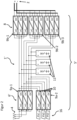
Die
Die in
Jede der in
Die erste Ladeschaltung 6, 6' der in den
In weiteren, nicht dargestellten Ausführungsformen der erfindungsgemäßen Ladesäule können jedoch auch zwei oder mehr als drei autarke Ladeeinheiten pro Lademodul vorgesehen sein, sodass eine Untergliederung des ersten Lade-/Speicherstrangs 5, 5' in lediglich zwei Teilstränge oder aber in mehr als drei Teilstränge erfolgen kann.In further, not shown embodiments of the charging station according to the invention, however, two or more than three autonomous charging units per charging module can also be provided, so that the first charging/
Auch können die einzelnen autarken Ladeeinheiten des ersten Lademoduls in einer weiteren Ausführungsform an ein anderes Speisestromnetz als an ein Drehstromnetz elektrisch angeschlossen sein. Beispielsweise können jeweils zwei Phasen jeder einzelnen autarken Ladeeinheit des ersten Lademoduls an jeweils zumindest ein Photovoltaikmodul einer von dem Speisestromnetz umfassten Photovoltaikanlage, oder auch an ein beliebiges anderes Gleichstromnetz, elektrisch angeschlossen sein.In a further embodiment, the individual self-sufficient charging units of the first charging module can also be electrically connected to a power supply system other than a three-phase system. For example, two phases of each individual self-sufficient charging unit of the first charging module can be connected to at least one Photovoltaic module of a photovoltaic system included in the power supply network, or to any other direct current network, be electrically connected.
Wie in
Gemäß
Zudem sind auch Ausführungsformen von der Erfindung umfasst, bei denen die zuvor beschriebene Mehrzahl von elektrischen Energiespeichern 11 nicht von der erfindungsgemäßen Ladesäule umfasst ist, sondern beispielsweise von dem Betreiber der Ladesäule in Abhängigkeit von den mit der Ladesäule zu ladenden Elektrofahrzeugbatterien in die Ladesäule eingebaut bzw. mit der Ladesäule elektrisch gekoppelt werden kann.In addition, the invention also includes embodiments in which the previously described plurality of electrical
Wie in den
Durch den modularen Aufbau der erfindungsgemäßen Ladesäule 1, 1' gemäß
Da der technische Aufbau der in
Die elektrischen Energiespeicher 11 können jedoch auch, abgesehen von möglicherweise unterschiedlichen Alterungsprozessen, technisch gleich sein und die gleiche maximal speicherbare Energie, Nennspannung und den gleichen maximalen Lade- und Entladestrom aufweisen. In diesem Fall wird nur ein bestimmter Typ des elektrischen Energiespeichers 11 benötigt, was die Installation der Ladesäule 1' vereinfachen kann.However, apart from possibly different aging processes, the
Der modulare Aufbau des in
Die in
Im Gegensatz zu dem ersten Lademodul 9a-1 sind die autarken Ladeeinheiten 10 des zweiten Lademoduls 9a-2 jedoch auf deren Primärseite an in Reihe geschaltete Photovoltaikmodule einer Photovoltaikanlage 16, sogenannte Strings, angeschlossen, und nicht an jeweils zwei Phasen des Speisestromnetzes 4. Gemäß der in
Gemäß der in
Ferner können die elektrischen Energiespeicher 11 auch nur durch die autarken Ladeeinheiten 10 des zweiten Lademoduls 9a-2, und somit aus Solarenergie der Photovoltaikanlage 16, geladen werden, beispielsweise, wenn elektrische Energie aus dem Speisestromnetz 4 wegen eines Zusammenbrechens des Speisestromnetzes 4 nicht zur Verfügung steht. Ein Aufladen der elektrischen Energiespeicher 11 nur aus der Photovoltaikanlage 16 kann auch insbesondere bei entsprechend intensiver Sonneneinstrahlung von Relevanz sein, z.B. um das Speisestromnetz 4 nicht zu überlasten oder um Kosten zu sparen.Furthermore, the
Auch kann in einer weiteren, nicht dargestellten Ausführungsform der Erfindung vorgesehen sein, dass die erfindungsgemäße Ladesäule eine entsprechende Auswahleinrichtung, beispielsweise ein Bedienpanel oder anderweitige Bedienelemente wie Tasten, Drehknopf oder Schalter, aufweist. Mit Hilfe der Auswahleinrichtung kann der Fahrer des Elektrofahrzeugs an der erfindungsgemäßen Ladesäule auswählen, ob er sein Elektrofahrzeug nur mit Wechselstrom aus dem Stromnetz, nur mit Solarstrom aus der Photovoltaikanlage, und somit der Umwelt zuliebe nur mit Ökostrom, oder mit einer Kombination aus beiden Stromquellen laden möchte.In a further embodiment of the invention, not shown, it can also be provided that the charging station according to the invention has a corresponding selection device, for example a control panel or other control elements such as buttons, rotary knobs or switches. With the help of the selection device, the driver of the electric vehicle can choose at the charging station according to the invention whether he wants to charge his electric vehicle only with alternating current from the power grid, only with solar power from the photovoltaic system, and thus for the sake of the environment only with green electricity, or with a combination of both power sources would like.
Auch wenn aus Gründen der Übersichtlichkeit nicht dargestellt, so kann die in
Gemäß einer weiteren, in den Figuren nicht dargestellten Ausführungsform kann die erfindungsgemäße Ladesäule einen von dem ersten Lade-/Speicherstrang 5, 5' unabhängigen und elektrisch getrennten zweiten Lade-/Speicherstrang sowie einen zweiten Ladeanschluss zum elektrischen Gleichstromladen einer Batterie eines an den zweiten Ladeanschluss anschließbaren Elektrofahrzeugs aufweisen. Der erste Lade-/Speicherstrang 5, 5' und der zweite Lade-/Speicherstrang sind auf deren Primärseite zum Einspeisen von elektrischer Energie aus dem Speisestromnetz 4 parallelgeschaltet. Vorzugsweise gleicht ein solcher zweiter Lade-/Speicherstrang in seinem technischen Aufbau dem ersten Lade-/Speicherstrang 5, 5'.According to a further embodiment not shown in the figures, the charging station according to the invention can have a second charging/storage line that is independent and electrically separate from the first charging/
Primärseite und Sekundärseite jeder einzelnen autarken Ladeeinheit 10 eines Lademoduls 9a-1, 9a-2, 9b-1, 9b-2, 9b-3 sind in
Jede einzelne autarke Ladeeinheit 10 des ersten Lademoduls 9a-1 kann einen Leistungskorrekturfilter, auch Power Factor Correction (PFC) genannt, aufweisen, der jedoch in den
Auch wenn in den Figuren nicht explizit dargestellt, so umfasst die vorliegende Erfindung weiterhin eine Ladestation, welche eine Mehrzahl von Ladesäulen 1, 1' gemäß einer von der Erfindung umfassten Ausführungsformen aufweist.Even if not explicitly shown in the figures, the present invention also includes a charging station which has a plurality of charging
Aus vorstehender Beschreibung ist ferner offensichtlich, dass ein weiterer Vorteil der erfindungsgemäß eingesetzten Lademodule darin besteht, dass diese in einer weiteren Anwendung grundsätzlich jeweils auch einzeln, oder auch mehrere parallel betriebene Lademodule, an ein Speisenetz, z.B. das Speisestromnetz 4, angeschlossen und direkt mit einem Ausgang, z.B. dem Ladeanschluss 2, zum Laden der Batterie eines daran anschließbaren bzw. angeschlossenen Elektrofahrzeugs benutzt werden kann, also auch ohne zwischengeschaltete Energiespeicher, insbesondere Pufferbatterie.It is also obvious from the above description that another advantage of the charging modules used according to the invention is that in a further application they can also be connected individually, or also several charging modules operated in parallel, to a supply network, e.g. the supply current network 4, and connected directly to a Output, for example the charging
- 1, 1'1, 1'
- Ladesäulecharging station
- 22
- erster Ladeanschlussfirst charging port
- 44
- Speisestromnetzsupply network
- 5, 5'5, 5'
- erster Lade-/Speicherstrangfirst load/store line
- 6, 6'6, 6'
- erste Ladeschaltungfirst charging circuit
- 88th
- zweite Ladeschaltungsecond charging circuit
- 9a-1, 9a-29a-1, 9a-2
- erstes, zweites Lademodul der ersten Ladeschaltungfirst, second charging module of the first charging circuit
- 9b-i, i=1,...,n9b-i, i=1,...,n
- Lademodul der zweiten LadeschaltungCharging module of the second charging circuit
- 1010
- autarke Ladeeinheitself-sufficient loading unit
- 1111
- elektrischer Energiespeicherelectrical energy storage
- 1212
- Umwandlungseinrichtung UC->DCConversion device UC->DC
- 1616
- Photovoltaikanlagephotovoltaic system
Claims (9)
- Charging pillar (1, 1') having a first charging terminal (2) for the electrical direct current charging of a battery of an electric vehicle which can be connected to the first charging terminal (2), the charging pillar (1, 1') having a first charging/storage strand (5, 5') which- is electrically connected to the first charging terminal (2),- can be electrically coupled to at least one electrical energy storage device (11) and at least includes- a first charging circuit (6, 6') for charging the at least one electrical energy storage device (11) in the electrically coupled state with electrical energy from a supply network (4), and- a second charging circuit (8a) for charging the battery of an electric vehicle connectable to the first charging terminal (2) with electrical energy,
characterized in thatthe charging pillar (1, 1') is modularly constructed in such a way that it has a plurality of technically identical charging modules (9a-i, 9b-i), each individual charging module (9a-i, 9b-i) comprising a certain plurality of self-sufficient charging units (10) electrically separated from one another, and each individual self-sufficient charging unit (10) having a conversion device (12) for converting an input voltage into a direct current output voltage,wherein the first charging circuit (6, 6') has a first charging module (9a-1) and the 25 second charging circuit (8) has a plurality of charging modules (9b-i),so that the plurality of charging modules (9b-i) of the second charging circuit (8) is equal to the determined plurality of the electrically separated self-sufficient charging units (10) of a respective charging module (9a-i, 9b-i), wherein- each self-sufficient charging unit (10) of the first charging module (9a-1) of the first charging circuit (6, 6') can be electrically connected on its primary side to the supply network (4) during operation of the charging pillar (1, 1') and is designed on its secondary side for electrical connection to precisely one electrical energy store (11) in each case and, in the electrically connected state, for charging this electrical energy store (11) with electrical energy from the supply network (4),- all self-sufficient charging units (10) of a respective charging module (9b-1, 9b-2, 9b- 3) of the plurality of charging modules (9b-i) of the second charging circuit (8) are each designed jointly on their primary side for connection to precisely one electrical energy store (11) and, in the electrically connected state, for drawing electrical energy from this one electrical energy store (11), and- the self-sufficient charging units (10) of the charging modules (9b-i) of the second charging circuit (8) are connected in parallel on their secondary side and are electrically connected to the first charging connection (2) after their parallel connection. - Charging pillar (1, 1') according to claim 1, characterized in that the conversion device (12) of each individual self-sufficient charging unit (10) is designed to convert both a direct voltage and an alternating voltage into direct voltage.
- Charging pillar (1, 1') according to claim 1 or 2, characterized in that the charging pillar (1, 1') has a plurality of electrical energy storages (11), wherein each electrical energy storage (11) of the plurality of electrical energy storages (11) is connected to a respective self-sufficient charging unit (10) of the first charging module (9a-1) of the first charging circuit (6, 6') and to all self-sufficient charging units (10) of a respective charging module (9b-1, 9b-2, 9b-3) of the plurality of charging modules (9b- i) of the second charging circuit (8).
- Charging pillar (1, 1') according to claim 3, characterized in that the electrical energy storage (11) are different with regard to at least one variable from the group of their maximum storable energy, their nominal voltage, their maximum charging and discharging current and their state of charge.
- Charging pillar (1, 1') according to one of the claims 1-4, characterized in that each individual charging module (9a-i, 9b-i) has in each case precisely three self-sufficient charging units (10) electrically separated from one another, wherein each of the three self-sufficient charging units (10) of the first charging module (9a-1) of the first charging circuit (6, 6') can be electrically connected to in each case two phases of a supply network (4) designed as a three-phase network or to in each case at least one photovoltaic module of a photovoltaic system (16) comprised by the supply network (4) or to a supply network designed as a direct current network.
- Charging pillar (1') according to one of the claims 1-5, characterized in that the charging pillar (1') can be electrically connected to a photovoltaic system (16) comprising a plurality of photovoltaic modules and/or that the first charging circuit (6') of the first charging/storage strand (5') has a second charging module (9a-2) with the certain plurality of self-sufficient charging units (10) electrically separated from one another, so that each of the self-sufficient charging units (10) of the second charging module (9a-2) can be electrically connected on its primary side to at least one photovoltaic module, preferably to a multiplicity of series-connected photovoltaic modules, and is connected in parallel on its secondary side in each case to exactly one of the self-sufficient charging units (10) of the first charging module (9a-1).
- Charging pillar (1, 1') according to one of the claims 1-6, characterized in that the primary side and secondary side of each individual self-sufficient charging unit (10) of a charging module (9a-i, 9b-i) of the charging pillar (1, 1') are electrically isolated from one another.
- Charging pillar according to one of the claims 1-7, characterized in that the charging pillar has a second charging/storage strand which is independent of and electrically separate from the first charging/storage strand (5, 5'), as well as a second charging terminal for the electrical direct current charging of a battery of an electric vehicle which can be connected to the second charging terminal, wherein the first charging/storage strand (5, 5') and the second charging/storage strand are connected in parallel on their primary side for feeding in electrical energy from the supply network (4) and the second charging/storage strand is preferably similar in its technical construction to the first charging/storage strand (5, 5').
- Charging station with a plurality of charging pillars (1, 1') according to any of claims 1-6.
Applications Claiming Priority (1)
| Application Number | Priority Date | Filing Date | Title |
|---|---|---|---|
| LU101820A LU101820B1 (en) | 2020-05-25 | 2020-05-25 | Modular charging station for electric direct current charging of a battery of an electric vehicle |
Publications (2)
| Publication Number | Publication Date |
|---|---|
| EP3915825A1 EP3915825A1 (en) | 2021-12-01 |
| EP3915825B1 true EP3915825B1 (en) | 2023-02-15 |
Family
ID=71094746
Family Applications (1)
| Application Number | Title | Priority Date | Filing Date |
|---|---|---|---|
| EP21174892.6A Active EP3915825B1 (en) | 2020-05-25 | 2021-05-20 | Modular charging column for electric dc loading of a battery of an electric vehicle |
Country Status (5)
| Country | Link |
|---|---|
| EP (1) | EP3915825B1 (en) |
| DK (1) | DK3915825T3 (en) |
| ES (1) | ES2939600T3 (en) |
| LU (1) | LU101820B1 (en) |
| PT (1) | PT3915825T (en) |
Families Citing this family (1)
| Publication number | Priority date | Publication date | Assignee | Title |
|---|---|---|---|---|
| CN114613066A (en) * | 2022-03-25 | 2022-06-10 | 广东易正电气股份有限公司 | Automatic control charging method of charging pile |
Family Cites Families (5)
| Publication number | Priority date | Publication date | Assignee | Title |
|---|---|---|---|---|
| DE102016123924A1 (en) * | 2016-12-09 | 2018-06-14 | Dr. Ing. H.C. F. Porsche Aktiengesellschaft | Modular power electronics for charging an electrically powered vehicle |
| DE102017207102A1 (en) * | 2017-03-13 | 2018-09-13 | Bayerische Motoren Werke Aktiengesellschaft | Stationary storage for temporary storage of electrical energy in an electrical supply network and operating method and retrofit module for the stationary storage |
| DE102017130992A1 (en) * | 2017-12-21 | 2019-06-27 | Hochschule Osnabrück | Charging / discharging unit for connecting a mobile electrical energy storage to a voltage network |
| DE102018204057A1 (en) | 2018-03-16 | 2019-09-19 | Schäfer Elektronik Gmbh | Charging station for electric vehicles with at least two charging stations |
| DE102018218555A1 (en) * | 2018-10-30 | 2020-04-30 | Robert Bosch Gmbh | Device and method for charging several energy stores |
-
2020
- 2020-05-25 LU LU101820A patent/LU101820B1/en active IP Right Grant
-
2021
- 2021-05-20 ES ES21174892T patent/ES2939600T3/en active Active
- 2021-05-20 EP EP21174892.6A patent/EP3915825B1/en active Active
- 2021-05-20 PT PT211748926T patent/PT3915825T/en unknown
- 2021-05-20 DK DK21174892.6T patent/DK3915825T3/en active
Also Published As
| Publication number | Publication date |
|---|---|
| PT3915825T (en) | 2023-03-27 |
| ES2939600T3 (en) | 2023-04-25 |
| DK3915825T3 (en) | 2023-03-20 |
| EP3915825A1 (en) | 2021-12-01 |
| LU101820B1 (en) | 2021-11-25 |
Similar Documents
| Publication | Publication Date | Title |
|---|---|---|
| EP3333005B1 (en) | Modular power electronics unit for charging an electrically powered vehicle | |
| WO2018166815A1 (en) | Stationary storage device for temporarily storing electric energy in an electric supply grid, operating method, and retrofitting module for the stationary storage device | |
| EP3521099B1 (en) | Charging system with at least one charging column for electric vehicles and method for charging one or more electric vehicles | |
| EP3022835B1 (en) | Inverter comprising at least two direct current inputs, a photovoltaic installation comprising such an inverter, and a method for actuating an inverter | |
| EP3535839B1 (en) | Electrically coupling a high-voltage on-board electrical system to a low-voltage on-board electrical system | |
| DE102013102603A1 (en) | Method for a black start of a power plant with multiple inverters connectable to an AC grid | |
| DE102010032088A1 (en) | Method for heating battery system of electrically driven vehicle, involves supplying alternating current to battery or battery section in phase-shifted manner for supplying current to another battery or another battery section | |
| DE102016123923A1 (en) | loader | |
| EP3024130A1 (en) | DC/DC converter | |
| EP3092150A1 (en) | Electrochemical energy accumulator and balancing method | |
| EP2528767B1 (en) | Battery system for micro-hybrid vehicles comprising high-efficiency consumers | |
| WO2016113298A1 (en) | High-voltage battery for a motor vehicle, and motor vehicle | |
| WO2019101443A1 (en) | Method for operating an electrical energy storage device for a motor vehicle, and corresponding energy storage device | |
| EP2544327B1 (en) | Energy storage assembly and fluctuating load | |
| EP2254218B1 (en) | Device and method for charging batteries | |
| DE102020113907A1 (en) | Modular charging station for electric direct current charging of a battery of an electric vehicle | |
| EP3915825B1 (en) | Modular charging column for electric dc loading of a battery of an electric vehicle | |
| EP2862255A2 (en) | Switching device for a battery and corresponding switching method | |
| DE102015007264B4 (en) | Fast transfer of electrical energy from a charging station to a consumer | |
| DE102017128573B3 (en) | Charging arrangement for an electric vehicle on a medium-voltage network and method for its operation | |
| DE102016002459A1 (en) | Electrical system for an electrically driven motor vehicle | |
| WO2017008927A1 (en) | Device and method for inductively transmitting electrical energy to movable electrical consumers | |
| WO2012038210A2 (en) | Energy supply system and method for charging at least one energy storage cell acting as energy store for a dc-voltage intermediate circuit in an energy supply system | |
| WO2017125347A1 (en) | Improved energy storage arrangement comprising multiple energy stores | |
| WO2019215194A1 (en) | Efficient converter assembly for a charging system for an electric vehicle including mains grid, battery store and other sources |
Legal Events
| Date | Code | Title | Description |
|---|---|---|---|
| PUAI | Public reference made under article 153(3) epc to a published international application that has entered the european phase |
Free format text: ORIGINAL CODE: 0009012 |
|
| STAA | Information on the status of an ep patent application or granted ep patent |
Free format text: STATUS: REQUEST FOR EXAMINATION WAS MADE |
|
| 17P | Request for examination filed |
Effective date: 20210525 |
|
| AK | Designated contracting states |
Kind code of ref document: A1 Designated state(s): AL AT BE BG CH CY CZ DE DK EE ES FI FR GB GR HR HU IE IS IT LI LT LU LV MC MK MT NL NO PL PT RO RS SE SI SK SM TR |
|
| B565 | Issuance of search results under rule 164(2) epc |
Effective date: 20211029 |
|
| GRAP | Despatch of communication of intention to grant a patent |
Free format text: ORIGINAL CODE: EPIDOSNIGR1 |
|
| STAA | Information on the status of an ep patent application or granted ep patent |
Free format text: STATUS: GRANT OF PATENT IS INTENDED |
|
| INTG | Intention to grant announced |
Effective date: 20220923 |
|
| GRAS | Grant fee paid |
Free format text: ORIGINAL CODE: EPIDOSNIGR3 |
|
| GRAA | (expected) grant |
Free format text: ORIGINAL CODE: 0009210 |
|
| STAA | Information on the status of an ep patent application or granted ep patent |
Free format text: STATUS: THE PATENT HAS BEEN GRANTED |
|
| AK | Designated contracting states |
Kind code of ref document: B1 Designated state(s): AL AT BE BG CH CY CZ DE DK EE ES FI FR GB GR HR HU IE IS IT LI LT LU LV MC MK MT NL NO PL PT RO RS SE SI SK SM TR |
|
| REG | Reference to a national code |
Ref country code: CH Ref legal event code: EP Ref country code: GB Ref legal event code: FG4D Free format text: NOT ENGLISH |
|
| REG | Reference to a national code |
Ref country code: DE Ref legal event code: R096 Ref document number: 502021000432 Country of ref document: DE |
|
| REG | Reference to a national code |
Ref country code: NL Ref legal event code: FP Ref country code: AT Ref legal event code: REF Ref document number: 1548079 Country of ref document: AT Kind code of ref document: T Effective date: 20230315 Ref country code: IE Ref legal event code: FG4D Free format text: LANGUAGE OF EP DOCUMENT: GERMAN |
|
| REG | Reference to a national code |
Ref country code: DK Ref legal event code: T3 Effective date: 20230315 |
|
| REG | Reference to a national code |
Ref country code: SE Ref legal event code: TRGR |
|
| REG | Reference to a national code |
Ref country code: PT Ref legal event code: SC4A Ref document number: 3915825 Country of ref document: PT Date of ref document: 20230327 Kind code of ref document: T Free format text: AVAILABILITY OF NATIONAL TRANSLATION Effective date: 20230321 |
|
| REG | Reference to a national code |
Ref country code: NO Ref legal event code: T2 Effective date: 20230215 |
|
| REG | Reference to a national code |
Ref country code: ES Ref legal event code: FG2A Ref document number: 2939600 Country of ref document: ES Kind code of ref document: T3 Effective date: 20230425 |
|
| REG | Reference to a national code |
Ref country code: LT Ref legal event code: MG9D |
|
| P01 | Opt-out of the competence of the unified patent court (upc) registered |
Effective date: 20230424 |
|
| PG25 | Lapsed in a contracting state [announced via postgrant information from national office to epo] |
Ref country code: RS Free format text: LAPSE BECAUSE OF FAILURE TO SUBMIT A TRANSLATION OF THE DESCRIPTION OR TO PAY THE FEE WITHIN THE PRESCRIBED TIME-LIMIT Effective date: 20230215 Ref country code: LV Free format text: LAPSE BECAUSE OF FAILURE TO SUBMIT A TRANSLATION OF THE DESCRIPTION OR TO PAY THE FEE WITHIN THE PRESCRIBED TIME-LIMIT Effective date: 20230215 Ref country code: LT Free format text: LAPSE BECAUSE OF FAILURE TO SUBMIT A TRANSLATION OF THE DESCRIPTION OR TO PAY THE FEE WITHIN THE PRESCRIBED TIME-LIMIT Effective date: 20230215 Ref country code: HR Free format text: LAPSE BECAUSE OF FAILURE TO SUBMIT A TRANSLATION OF THE DESCRIPTION OR TO PAY THE FEE WITHIN THE PRESCRIBED TIME-LIMIT Effective date: 20230215 |
|
| PGFP | Annual fee paid to national office [announced via postgrant information from national office to epo] |
Ref country code: PT Payment date: 20230508 Year of fee payment: 3 Ref country code: NO Payment date: 20230519 Year of fee payment: 3 Ref country code: IT Payment date: 20230531 Year of fee payment: 3 Ref country code: ES Payment date: 20230612 Year of fee payment: 3 Ref country code: DK Payment date: 20230524 Year of fee payment: 3 |
|
| PG25 | Lapsed in a contracting state [announced via postgrant information from national office to epo] |
Ref country code: PL Free format text: LAPSE BECAUSE OF FAILURE TO SUBMIT A TRANSLATION OF THE DESCRIPTION OR TO PAY THE FEE WITHIN THE PRESCRIBED TIME-LIMIT Effective date: 20230215 Ref country code: IS Free format text: LAPSE BECAUSE OF FAILURE TO SUBMIT A TRANSLATION OF THE DESCRIPTION OR TO PAY THE FEE WITHIN THE PRESCRIBED TIME-LIMIT Effective date: 20230615 Ref country code: GR Free format text: LAPSE BECAUSE OF FAILURE TO SUBMIT A TRANSLATION OF THE DESCRIPTION OR TO PAY THE FEE WITHIN THE PRESCRIBED TIME-LIMIT Effective date: 20230516 Ref country code: FI Free format text: LAPSE BECAUSE OF FAILURE TO SUBMIT A TRANSLATION OF THE DESCRIPTION OR TO PAY THE FEE WITHIN THE PRESCRIBED TIME-LIMIT Effective date: 20230215 |
|
| PGFP | Annual fee paid to national office [announced via postgrant information from national office to epo] |
Ref country code: SE Payment date: 20230524 Year of fee payment: 3 |
|
| PG25 | Lapsed in a contracting state [announced via postgrant information from national office to epo] |
Ref country code: SM Free format text: LAPSE BECAUSE OF FAILURE TO SUBMIT A TRANSLATION OF THE DESCRIPTION OR TO PAY THE FEE WITHIN THE PRESCRIBED TIME-LIMIT Effective date: 20230215 Ref country code: RO Free format text: LAPSE BECAUSE OF FAILURE TO SUBMIT A TRANSLATION OF THE DESCRIPTION OR TO PAY THE FEE WITHIN THE PRESCRIBED TIME-LIMIT Effective date: 20230215 Ref country code: EE Free format text: LAPSE BECAUSE OF FAILURE TO SUBMIT A TRANSLATION OF THE DESCRIPTION OR TO PAY THE FEE WITHIN THE PRESCRIBED TIME-LIMIT Effective date: 20230215 Ref country code: CZ Free format text: LAPSE BECAUSE OF FAILURE TO SUBMIT A TRANSLATION OF THE DESCRIPTION OR TO PAY THE FEE WITHIN THE PRESCRIBED TIME-LIMIT Effective date: 20230215 |
|
| REG | Reference to a national code |
Ref country code: DE Ref legal event code: R097 Ref document number: 502021000432 Country of ref document: DE |
|
| PG25 | Lapsed in a contracting state [announced via postgrant information from national office to epo] |
Ref country code: SK Free format text: LAPSE BECAUSE OF FAILURE TO SUBMIT A TRANSLATION OF THE DESCRIPTION OR TO PAY THE FEE WITHIN THE PRESCRIBED TIME-LIMIT Effective date: 20230215 |
|
| PGFP | Annual fee paid to national office [announced via postgrant information from national office to epo] |
Ref country code: DE Payment date: 20230726 Year of fee payment: 3 |
|
| PLBE | No opposition filed within time limit |
Free format text: ORIGINAL CODE: 0009261 |
|
| STAA | Information on the status of an ep patent application or granted ep patent |
Free format text: STATUS: NO OPPOSITION FILED WITHIN TIME LIMIT |
|
| PG25 | Lapsed in a contracting state [announced via postgrant information from national office to epo] |
Ref country code: MC Free format text: LAPSE BECAUSE OF FAILURE TO SUBMIT A TRANSLATION OF THE DESCRIPTION OR TO PAY THE FEE WITHIN THE PRESCRIBED TIME-LIMIT Effective date: 20230215 |
|
| 26N | No opposition filed |
Effective date: 20231116 |
|
| REG | Reference to a national code |
Ref country code: BE Ref legal event code: MM Effective date: 20230531 |
|
| PG25 | Lapsed in a contracting state [announced via postgrant information from national office to epo] |
Ref country code: SI Free format text: LAPSE BECAUSE OF FAILURE TO SUBMIT A TRANSLATION OF THE DESCRIPTION OR TO PAY THE FEE WITHIN THE PRESCRIBED TIME-LIMIT Effective date: 20230215 Ref country code: MC Free format text: LAPSE BECAUSE OF FAILURE TO SUBMIT A TRANSLATION OF THE DESCRIPTION OR TO PAY THE FEE WITHIN THE PRESCRIBED TIME-LIMIT Effective date: 20230215 Ref country code: LU Free format text: LAPSE BECAUSE OF NON-PAYMENT OF DUE FEES Effective date: 20230520 |
|
| REG | Reference to a national code |
Ref country code: IE Ref legal event code: MM4A |
|
| PG25 | Lapsed in a contracting state [announced via postgrant information from national office to epo] |
Ref country code: IE Free format text: LAPSE BECAUSE OF NON-PAYMENT OF DUE FEES Effective date: 20230520 |
|
| PG25 | Lapsed in a contracting state [announced via postgrant information from national office to epo] |
Ref country code: IE Free format text: LAPSE BECAUSE OF NON-PAYMENT OF DUE FEES Effective date: 20230520 |