EP3915794A1 - Sheet feeding device and image forming apparatus incorporating same - Google Patents
Sheet feeding device and image forming apparatus incorporating same Download PDFInfo
- Publication number
- EP3915794A1 EP3915794A1 EP21175500.4A EP21175500A EP3915794A1 EP 3915794 A1 EP3915794 A1 EP 3915794A1 EP 21175500 A EP21175500 A EP 21175500A EP 3915794 A1 EP3915794 A1 EP 3915794A1
- Authority
- EP
- European Patent Office
- Prior art keywords
- leading end
- continuous sheet
- time
- change rate
- roll
- Prior art date
- Legal status (The legal status is an assumption and is not a legal conclusion. Google has not performed a legal analysis and makes no representation as to the accuracy of the status listed.)
- Granted
Links
Images







Classifications
-
- B—PERFORMING OPERATIONS; TRANSPORTING
- B41—PRINTING; LINING MACHINES; TYPEWRITERS; STAMPS
- B41J—TYPEWRITERS; SELECTIVE PRINTING MECHANISMS, i.e. MECHANISMS PRINTING OTHERWISE THAN FROM A FORME; CORRECTION OF TYPOGRAPHICAL ERRORS
- B41J11/00—Devices or arrangements of selective printing mechanisms, e.g. ink-jet printers or thermal printers, for supporting or handling copy material in sheet or web form
- B41J11/006—Means for preventing paper jams or for facilitating their removal
-
- B—PERFORMING OPERATIONS; TRANSPORTING
- B41—PRINTING; LINING MACHINES; TYPEWRITERS; STAMPS
- B41J—TYPEWRITERS; SELECTIVE PRINTING MECHANISMS, i.e. MECHANISMS PRINTING OTHERWISE THAN FROM A FORME; CORRECTION OF TYPOGRAPHICAL ERRORS
- B41J15/00—Devices or arrangements of selective printing mechanisms, e.g. ink-jet printers or thermal printers, specially adapted for supporting or handling copy material in continuous form, e.g. webs
- B41J15/04—Supporting, feeding, or guiding devices; Mountings for web rolls or spindles
-
- B—PERFORMING OPERATIONS; TRANSPORTING
- B41—PRINTING; LINING MACHINES; TYPEWRITERS; STAMPS
- B41J—TYPEWRITERS; SELECTIVE PRINTING MECHANISMS, i.e. MECHANISMS PRINTING OTHERWISE THAN FROM A FORME; CORRECTION OF TYPOGRAPHICAL ERRORS
- B41J11/00—Devices or arrangements of selective printing mechanisms, e.g. ink-jet printers or thermal printers, for supporting or handling copy material in sheet or web form
- B41J11/0095—Detecting means for copy material, e.g. for detecting or sensing presence of copy material or its leading or trailing end
-
- B—PERFORMING OPERATIONS; TRANSPORTING
- B41—PRINTING; LINING MACHINES; TYPEWRITERS; STAMPS
- B41J—TYPEWRITERS; SELECTIVE PRINTING MECHANISMS, i.e. MECHANISMS PRINTING OTHERWISE THAN FROM A FORME; CORRECTION OF TYPOGRAPHICAL ERRORS
- B41J15/00—Devices or arrangements of selective printing mechanisms, e.g. ink-jet printers or thermal printers, specially adapted for supporting or handling copy material in continuous form, e.g. webs
- B41J15/18—Multiple web-feeding apparatus
-
- B—PERFORMING OPERATIONS; TRANSPORTING
- B65—CONVEYING; PACKING; STORING; HANDLING THIN OR FILAMENTARY MATERIAL
- B65H—HANDLING THIN OR FILAMENTARY MATERIAL, e.g. SHEETS, WEBS, CABLES
- B65H16/00—Unwinding, paying-out webs
- B65H16/005—Dispensers, i.e. machines for unwinding only parts of web roll
-
- B—PERFORMING OPERATIONS; TRANSPORTING
- B65—CONVEYING; PACKING; STORING; HANDLING THIN OR FILAMENTARY MATERIAL
- B65H—HANDLING THIN OR FILAMENTARY MATERIAL, e.g. SHEETS, WEBS, CABLES
- B65H16/00—Unwinding, paying-out webs
- B65H16/10—Arrangements for effecting positive rotation of web roll
- B65H16/103—Arrangements for effecting positive rotation of web roll in which power is applied to web-roll spindle
-
- B—PERFORMING OPERATIONS; TRANSPORTING
- B65—CONVEYING; PACKING; STORING; HANDLING THIN OR FILAMENTARY MATERIAL
- B65H—HANDLING THIN OR FILAMENTARY MATERIAL, e.g. SHEETS, WEBS, CABLES
- B65H23/00—Registering, tensioning, smoothing or guiding webs
- B65H23/04—Registering, tensioning, smoothing or guiding webs longitudinally
- B65H23/18—Registering, tensioning, smoothing or guiding webs longitudinally by controlling or regulating the web-advancing mechanism, e.g. mechanism acting on the running web
- B65H23/182—Registering, tensioning, smoothing or guiding webs longitudinally by controlling or regulating the web-advancing mechanism, e.g. mechanism acting on the running web in unwinding mechanisms or in connection with unwinding operations
- B65H23/185—Registering, tensioning, smoothing or guiding webs longitudinally by controlling or regulating the web-advancing mechanism, e.g. mechanism acting on the running web in unwinding mechanisms or in connection with unwinding operations motor-controlled
-
- B—PERFORMING OPERATIONS; TRANSPORTING
- B65—CONVEYING; PACKING; STORING; HANDLING THIN OR FILAMENTARY MATERIAL
- B65H—HANDLING THIN OR FILAMENTARY MATERIAL, e.g. SHEETS, WEBS, CABLES
- B65H2301/00—Handling processes for sheets or webs
- B65H2301/40—Type of handling process
- B65H2301/44—Moving, forwarding, guiding material
- B65H2301/443—Moving, forwarding, guiding material by acting on surface of handled material
- B65H2301/4431—Moving, forwarding, guiding material by acting on surface of handled material by means with operating surfaces contacting opposite faces of material
- B65H2301/44318—Moving, forwarding, guiding material by acting on surface of handled material by means with operating surfaces contacting opposite faces of material between rollers
-
- B—PERFORMING OPERATIONS; TRANSPORTING
- B65—CONVEYING; PACKING; STORING; HANDLING THIN OR FILAMENTARY MATERIAL
- B65H—HANDLING THIN OR FILAMENTARY MATERIAL, e.g. SHEETS, WEBS, CABLES
- B65H2301/00—Handling processes for sheets or webs
- B65H2301/50—Auxiliary process performed during handling process
- B65H2301/52—Auxiliary process performed during handling process for starting
- B65H2301/522—Threading web into machine
-
- B—PERFORMING OPERATIONS; TRANSPORTING
- B65—CONVEYING; PACKING; STORING; HANDLING THIN OR FILAMENTARY MATERIAL
- B65H—HANDLING THIN OR FILAMENTARY MATERIAL, e.g. SHEETS, WEBS, CABLES
- B65H2513/00—Dynamic entities; Timing aspects
- B65H2513/50—Timing
- B65H2513/52—Age; Duration; Life time or chronology of event
-
- B—PERFORMING OPERATIONS; TRANSPORTING
- B65—CONVEYING; PACKING; STORING; HANDLING THIN OR FILAMENTARY MATERIAL
- B65H—HANDLING THIN OR FILAMENTARY MATERIAL, e.g. SHEETS, WEBS, CABLES
- B65H2801/00—Application field
- B65H2801/03—Image reproduction devices
- B65H2801/06—Office-type machines, e.g. photocopiers
Definitions
- Embodiments of the present disclosure relate to a sheet feeding device and an image forming apparatus incorporating the sheet feeding device.
- the image forming apparatus that forms an image on a long sheet (hereinafter, referred to as a "continuous sheet") wound around a spool.
- the image forming apparatus using the continuous sheet includes a sheet feeding mechanism. A user manually inserts a leading end of the continuous sheet into a sheet feeding portion of the sheet feeding mechanism, and then the image forming apparatus performs a sheet feeding operation after detecting the leading end.
- Japanese Unexamined Patent Application Publication No. 2018-150107 discloses a technique in which the spool is reversely rotated in a winding direction to wind the continuous sheet, a leading end peeled from the roll of the continuous sheet is detected by a sensor, and the spool is forwardly rotated in a feeding direction to feed the continuous sheet whose leading end has been detected.
- the present disclosure has been made to solve such a situation, and an object thereof is to provide a technique of stably detecting a leading end of a continuous sheet regardless of the type of the continuous sheet in a sheet feeding device that feeds the continuous sheet wound around a spool.
- Embodiments of the present disclosure describe an improved sheet feeding device that includes a support, a rotation driver, a guide, a support shaft, a biasing member, a sensor, a roller, and circuitry.
- the support detachably supports a roll formed of a continuous sheet wound around a spool.
- the rotation driver rotates the spool supported by the support in a feeding direction and a winding direction of the continuous sheet.
- the guide includes a facing portion that faces an outer circumferential surface of the roll and a guide portion that extends downstream from the facing portion in the feeding direction.
- the support shaft swingably supports the guide around a downstream end of the guide in the feeding direction, in a direction in which the facing portion contacts and separates from the roll.
- the biasing member presses the guide in a direction in which the facing portion approaches the roll.
- the sensor retractably projects from the facing portion toward the roll to contact the roll and outputs a detection signal having a signal level in response to an amount of projection of the sensor.
- the roller supported by the facing portion contacts the outer circumferential surface of the roll at a different position from the sensor in a circumferential direction of the roll.
- the circuitry controls the rotation driver based on a signal change rate that is an amount of change in the signal level of the detection signal per unit time.
- the circuitry causes the rotation driver to rotate the spool in the winding direction to determine a passing time at which a leading end of the continuous sheet passes through the sensor based on a first change rate that is the signal change rate when the senser retracts and a second change rate that is the signal change rate when the sensor projects. Further, the circuitry causes the rotation driver to rotate the spool by a predetermined angle in the winding direction, from the passing time, to position the leading end at a feeding start position that is upstream from the sensor and the roller in the winding direction and facing the guide portion, and causes the rotation driver to rotate the spool in the feeding direction to feed the continuous sheet from the feeding start position along the guide portion.
- the sheet feeding device feeds the continuous sheet wound around the spool, and can stably detect the leading end of the continuous sheet regardless of the type of the continuous sheet.
- each reference numeral indicates only that components indicated thereby are used for forming yellow, magenta, cyan, and black images, respectively, and hereinafter may be omitted when color discrimination is not necessary.
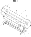
- FIG. 1 is an exterior perspective view of the image forming apparatus 1 according to the present embodiment.
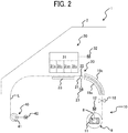
- FIG. 2 is a cross-sectional view illustrating an interior of the image forming apparatus 1.
- a housing of the image forming apparatus 1 has an exterior constructed of a center cover 2, a right cover 3 and a left cover 4 disposed on the left and right of the center cover 2, side plates 5 disposed at ends of the right cover 3 and the left cover 4, and an operation cover 6 that opens and closes respect to the center cover 2.
- An apparatus body of the image forming apparatus 1 covered with the respective covers 2 to 6 is supported by left and right legs 7 with casters.
- the image forming apparatus 1 is an image forming apparatus using an inkjet method that discharges ink onto a continuous sheet P (long sheet) to form an image on the continuous sheet P.
- a method of image formation used by the image forming apparatus 1 is not limited to the inkjet method, and an electrophotographic method can be used.
- the image forming apparatus 1 mainly includes a sheet feeding device 10, a conveyance unit 20, an image forming unit 30, a winding unit 40, and a controller 50 (see FIG. 8 ).
- the sheet feeding device 10 feeds the continuous sheet P wound around a spool 8 to the conveyance unit 20 through a conveyance path L.
- the conveyance path L is a space through which the continuous sheet P passes inside the image forming apparatus 1. More specifically, the conveyance path L is a route from the sheet feeding device 10 to the winding unit 40 via the conveyance unit 20 and the image forming unit 30. Details of the sheet feeding device 10 is described later with reference to FIGS. 3 to 7 .
- the conveyance unit 20 conveys the continuous sheet P, which is fed from the sheet feeding device 10 through the conveyance path L, to the winding unit 40 through a position facing the image forming unit 30.
- the conveyance unit 20 mainly includes a conveyance roller 21, a pressure roller 22, and a conveyance motor 23.
- the conveyance roller 21 and the pressure roller 22 rotate while nipping the continuous sheet P from both sides in the direction of thickness of the continuous sheet P.
- the conveyance motor 23 transmits a driving force to rotate the conveyance roller 21.
- the pressure roller 22 is pressed against the conveyance roller 21 with a predetermined pressure and rotated along with the rotation of the conveyance roller 21.
- the image forming unit 30 is disposed downstream from the conveyance unit 20 in the direction of conveyance of the continuous sheet P.
- the image forming unit 30 discharges ink onto the continuous sheet P conveyed by the conveyance unit 20 to form an image on the continuous sheet P.
- the image forming unit 30 mainly includes a carriage 31, a main scanning motor 32, and a platen 33.
- the carriage 31 reciprocates in the main scanning direction perpendicular to the direction of conveyance of the continuous sheet P.
- the carriage 31 includes recording heads 31k, 31c, 31m, and 31y that discharge inks of respective colors of black, cyan, magenta, and yellow.
- the recording heads 31k, 31c, 31m, and 31y discharge the inks of the respective colors toward the continuous sheet P supported by the platen 33 in accordance with instructions from the controller 50.
- the platen 33 upwardly faces the carriage 31.
- the platen 33 supports the continuous sheet P conveyed by the conveyance unit 20.
- the winding unit 40 is disposed downstream from the conveyance unit 20 and the image forming unit 30 in the direction of conveyance of the continuous sheet P.
- the winding unit 40 winds the continuous sheet P on which an image has been formed by the image forming unit 30.
- the winding unit 40 mainly includes a winding roller 41 and a winding motor 42. As the winding motor 42 transmits a driving force, the winding roller 41 rotates to wind the continuous sheet P on which the image has been formed.
- FIGS. 15A to 15E are schematic views for explaining the comparative method of setting the rolled sheet.
- the rolled sheet is provided with flanges at the ends in a width direction of the rolled sheet, and a spool is set into the rolled sheet.
- a user sets the rolled sheet with the spool in a sheet holding portion (spool bearing mount) of an apparatus as illustrated in FIG. 15A , searches for a leading end of a continuous sheet of the rolled sheet, holds the rolled sheet with both hands as illustrated in FIG. 15B while keeping an eye on the leading end, and rotates the rolled sheet so that the leading end of the continuous sheet reaches the front side.
- the user guides the leading end of the continuous sheet between guide plates disposed on the back side of the rolled sheet and inserts the leading end while rotating the rolled sheet as illustrated in FIG. 15C .
- the apparatus holds the leading end and pull the continuous sheet therein.
- the guide plates between which the leading end of the continuous sheet is inserted is located on the back side of the rolled sheet, the guide plates are hidden behind the rolled sheet. Accordingly, it is difficult for the user to see the guide plates and confirm whether the leading end has been inserted between the guide plates. In addition, the user is required to insert the leading end of the continuous sheet of the rolled sheet as evenly as possible, which is a delicate operation. If the leading end of the continuous sheet is not inserted evenly, the continuous sheet is fed obliquely, which may cause skew or jam of the continuous sheet, and the user may have to reset the rolled sheet.
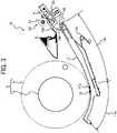
- FIG. 3 is a schematic view illustrating a configuration of the sheet feeding device 10.
- FIG. 4 is a perspective view of a guide arm 13 of the sheet feeding device 10.
- the sheet feeding device 10 mainly includes a support 11, a feed motor 12 as a rotation driver, the guide arm 13 as a guide, a support shaft 14, a coil spring 15 as a biasing member, a leading end sensor 16, multiple rollers 17a and 17b, a cutter 18, and guide plates 19a and 19b.
- the support 11 detachably supports a roll 9.
- the roll 9 is a rolled sheet formed by winding the continuous sheet P around the spool 8 having a shaft shape. More specifically, the support 11 rotatably supports both ends of the spool 8.
- the feed motor 12 rotates the spool 8 supported by the support 11 forward in the counterclockwise direction in FIG. 3 , that is, in a feeding direction to feed the continuous sheet P from the roll 9, and rotates the spool 8 in reverse in the clockwise direction in FIG. 3 , that is, in a winding direction to wind the continuous sheet P.
- the guide arm 13 brings the leading end sensor 16 and the rollers 17a and 17b into contact with the roll 9 and guides the continuous sheet P fed from the roll 9 between the guide plates 19a and 19b.
- the guide arm 13 has an elongated plate shape.
- the guide arm 13 includes a facing portion 13a and a guide portion 13b.
- the facing portion 13a has an arc shape along the outer circumferential surface of the roll 9.
- the facing portion 13a faces the outer circumferential surface of the roll 9 below a horizontal line passing through the center of rotation of the spool 8. More specifically, the facing portion 13a faces a region (lower region) including the lower end of the roll 9.
- the guide portion 13b extends downstream from the facing portion 13a in the feeding direction of the continuous sheet P. More specifically, the guide portion 13b extends from the facing portion 13a to a position between the guide plates 19a and 19b.
- the support shaft 14 extends in the same direction as the longitudinal direction of the spool 8 supported by the support 11.
- the support shaft 14 is secured inside the covers 2 to 6.
- the support shaft 14 is attached to a downstream end of the guide portion 13b in the feeding direction of the continuous sheet P, and swingably supports the guide arm 13. That is, the guide arm 13 is swingable around the support shaft 14 so that the facing portion 13a contacts and separates from the roll 9.
- the coil spring 15 presses the guide arm 13 in a direction in which the facing portion 13a approaches the roll 9.
- the leading end sensor 16 projects from the facing portion 13a toward the roll 9.
- the leading end sensor 16 is supported by the facing portion 13a and retractable with respect to the facing portion 13a. Further, the leading end sensor 16 is biased in a direction in which the leading end sensor 16 comes into contact with the outer circumferential surface of the roll 9, that is, in a direction in which the leading end sensor 16 projects from the facing portion 13a.
- the leading end sensor 16 outputs a detection signal to the controller 50.
- the detection signal has a signal level in response to an amount of projection of the leading end sensor 16 from the facing portion 13a. More specifically, the signal level of the detection signal increases as the amount of projection increases, and decreases as the amount of projection decreases.
- the rollers 17a and 17b are rotatably supported by the facing portion 13a.
- the axis of rotation of the rollers 17a and 17b extends in the same direction as the longitudinal direction of the spool 8 and the support shaft 14.
- the rollers 17a and 17b are disposed at a different position from the leading end sensor 16 in a circumferential direction of the roll 9. More specifically, the rollers 17a and 17b are disposed upstream from the leading end sensor 16 in the winding direction. Further, the rollers 17a and 17b are disposed separately from each other in the width direction perpendicular to the circumferential direction of the roll 9. More specifically, the leading end sensor 16 is disposed between the roller 17a and the roller 17b in the width direction.
- the cutter 18 cuts the leading end of the continuous sheet P over the entire region in the width direction.
- the cutting line by the cutter 18 extends in the direction perpendicular to the feeding direction of the continuous sheet P. That is, when the leading end of the continuous sheet P is inclined (skewed) with respect to the feeding direction, the cutter 18 cuts the leading end of the continuous sheet P to make the leading end of the continuous sheet P perpendicular to the feeding direction.
- the guide plates 19a and 19b are disposed downstream from the guide arm 13 in the feeding direction of the continuous sheet P.
- the guide plates 19a and 19b faces each other across the conveyance path L.
- the continuous sheet P moves along the guide arm 13, passes between the guide plates 19a and 19b, and enters the conveyance unit 20. That is, the guide plates 19a and 19b serve as a sheet feeding portion into which the continuous sheet P fed from the roll 9 enters.
- FIG. 5 is an enlarged view of the facing portion 13a and the surrounding thereof.
- FIGS. 6A to 6C are diagrams illustrating a positional relation between the leading end of the continuous sheet P, the leading end sensor 16, and the roller 17a.
- FIGS. 7A and 7B are diagrams illustrating change of the signal level of the detection signal of the leading end sensor 16.
- the leading end sensor 16 and the rollers 17a and 17b contact the outer circumferential surface of the roll 9.
- the leading end of the continuous sheet P that is in close contact with the outer circumferential surface of the roll 9 passes through the rollers 17a and 17b, and then passes through the leading end sensor 16.
- the detection signal of the leading end sensor 16 is High signal before the leading end of the continuous sheet P passes through the rollers 17a and 17b (region ⁇ ), and is Low signal after the leading end of the continuous sheet P passes through the rollers 17a and 17b (region ⁇ ).
- the High signal has a higher signal level than the Low signal. That is, the signal level of the detection signal of the leading end sensor 16 decreases as the leading end of the continuous sheet P passes through the rollers 17a and 17b.
- the leading end sensor 16 projects from the facing portion 13a by the thickness of the continuous sheet P. That is, when the leading end of the continuous sheet P passes through the leading end sensor 16, the amount of projection of the leading end sensor 16 increases.
- the detection signal of the leading end sensor 16 becomes the High signal after the leading end of the continuous sheet P passes through the leading end sensor 16 (region ⁇ ). That is, the signal level of the detection signal of the leading end sensor 16 increases as the leading end of the continuous sheet P passes through the leading end sensor 16.
- the change in the signal level of the detection signal is microscopically observed in FIG. 7B .
- the detection signal of the leading end sensor 16 decreases by the signal level y1 during the time x1 as illustrated in FIG. 7B .
- the detection signal of the leading end sensor 16 increases by the signal level y2 during the time x2.
- the amount of change in the signal level of the detection signal per unit time is referred to as a "signal change rate".
- the signal change rate when the leading end sensor 16 retracts is referred to as a first change rate
- the signal change rate when the leading end sensor 16 projects is referred to as a second change rate. That is, the first change rate and the second change rate are opposite in the direction of change of the signal level.
- the first change rate K1 exceeds a predetermined first threshold when the leading end of the continuous sheet P passes through the rollers 17a and 17b.
- the second change rate K2 exceeds a predetermined second threshold when the leading end of the continuous sheet P passes through the leading end sensor 16.
- the first threshold and the second threshold are thresholds for absorbing small variations in the diameter of the roll 9.
- the first threshold and the second threshold may be the same value or different values.
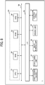
- FIG. 8 is a schematic block diagram illustrating a hardware configuration of the image forming apparatus 1.
- the image forming apparatus 1 includes a central processing unit (CPU) 51 as a control device, a random access memory (RAM) 52 as a storage device, a read only memory (ROM) 53 as a storage device, a hard disk drive (HDD) 54 as a storage device, and an interface (I/F) 55, which are connected via a common bus 56 as a communication device.
- the CPU 51, the RAM 52, the ROM 53, and the HDD 54 are examples of the controller 50 as circuitry.
- the CPU 51 is an arithmetic device and controls the overall operation of the image forming apparatus 1.
- the RAM 52 is a volatile storage medium in which data is read and written at high speed and used as a working area when the CPU 51 processes data.
- the ROM 53 is a non-volatile read only storage medium and stores programs such as firmware.
- the HDD 54 is a non-volatile storage medium with large storage capacity, in which data is read and written, and stores an operating system (OS), various control programs, application programs, and the like.
- OS operating system
- the image forming apparatus 1 processes various programs loaded from the ROM 53 or the HDD 54 to the RAM 52 by arithmetic functions provided in the CPU 51. By this processing, a software control unit including various functional modules of the image forming apparatus 1 is configured. The software control unit thus configured and the hardware resources installed in the image forming apparatus 1, in combination, construct functional blocks that implement the function of the image forming apparatus 1.
- the I/F 55 connects the sheet feeding device 10, the conveyance unit 20, the image forming unit 30, the winding unit 40, and a control panel (input unit) 57 to the common bus 56. That is, the controller 50 controls the sheet feeding device 10, the conveyance unit 20, the image forming unit 30, the winding unit 40, and the control panel 57 via the I/F 55.
- the control panel 57 is a user interface including a display that displays various types of information to be indicated to an operator, and buttons, switches, dials, and the like that accept operations by the operator.
- the control panel 57 may include a touch panel overlaid on the display. The control panel 57 accepts the operation by the operator and outputs an operation signal corresponding to the accepted operation to the controller 50.
- FIG. 9 is a flowchart of the sheet setting process.
- the sheet setting process when a new roll 9 is mounted on the support 11, the continuous sheet P of the roll 9 is fed to the conveyance unit 20 through between the guide plates 19a and 19b.
- the controller 50 controls the feed motor 12 based on the signal change rate of the leading end sensor 16.
- the sheet setting process starts, for example, when a sensor detects that the roll 9 is mounted on the sheet feeding device 10 or when the control panel 57 accepts an operation indicating that the roll 9 has been replaced.
- the controller 50 rotates the feed motor 12 in reverse to rotate the spool 8 in the winding direction (S901).
- the controller 50 executes a leading end detection process described later while rotating the feed motor 12 in the reverse (S902).
- the controller 50 determines whether the detection of the leading end of the continuous sheet P is successful in the leading end detection process (S903).
- the controller 50 determines that the detection of the leading end of the continuous sheet P is successful (Yes in S903), the controller 50 causes the feed motor 12 to rotate in reverse to rotate the spool 8 in the winding direction by a predetermined rotation angle (for example, about 355 degrees) from a passing time determined in the leading end detection process (S904).
- a predetermined rotation angle for example, about 355 degrees
- the passing time indicates when the leading end of the continuous sheet P passes through the leading end sensor 16.
- the feeding start position indicates a position upstream from the leading end sensor 16 and the rollers 17a and 17b in the winding direction and facing the guide portion 13b.
- the feeding start position is a position where the continuous sheet P is fed toward the guide plates 19a and 19b along the guide portion 13b when the spool 8 rotates in the feeding direction.
- the controller 50 causes the feed motor 12 to rotate forward to feed the continuous sheet P from the feeding start position along the guide portion 13b (S905).
- the continuous sheet P passes between the guide plates 19a and 19b and is nipped by the conveyance roller 21 and the pressure roller 22.
- the image forming apparatus 1 can execute an image forming process to form an image on the continuous sheet P. That is, the controller 50 drives the conveyance motor 23 to convey the continuous sheet P to a position facing the recording heads 31k, 31c, 31m, and 31y. Next, the controller 50 drives the main scanning motor 32 to move the carriage 31 in the main scanning direction and causes the recording heads 31k, 31c, 31m, and 31y to discharge ink. By repeating this process, an image is recorded on the continuous sheet P. Further, the controller 50 drives the winding motor 42 to wind the continuous sheet P on which the image is recorded on the winding roller 41.
- the controller 50 determines that the detection of the leading end of the continuous sheet P fails (No in S903), the controller 50 stops the feed motor 12 and displays an error on the control panel 57 (S906).
- the operator performs an appropriate operation (for example, remounting of the roll 9) according to the content of the error displayed on the control panel 57.
- FIG. 10 is a flowchart of the leading end detection process.
- FIG. 11 is a flowchart of an alternative detection process.
- FIG. 12 is a diagram illustrating the change of the signal level of the detection signal in the leading end detection process. During the leading end detection process and the alternative detection process, the spool 8 rotates in the winding direction.
- the controller 50 determines the passing time based on both the first change rate K1 and the second change rate K2.
- the controller 50 determines the passing time based on only the second change rate K2.
- the controller 50 determines the passing time in the leading end detection process, and when the controller 50 fails to detect the passing time in the leading end detection process, the controller 50 executes the alternative detection process. Note that the leading end detection process and the alternative detection process may be performed independently.
- the controller 50 initializes variables R and N stored in RAM 52 to 1 (S1001).
- the variable R represents the number of rotations of the spool 8 in the leading end detection process.
- the variable N represents the number of times the controller 50 determines the passing time in the leading end detection process.
- the controller 50 waits for subsequent processing until the first change rate K1 of the detection signal exceeds the first threshold (S1002) or until the second time t2 elapses (S1003).
- the controller 50 determines that the leading end of the continuous sheet P has passed through the rollers 17a and 17b when the first change rate K1 exceeds the first threshold during a predetermined third time range t3 (Yes in S1002) until the second time t2 elapses (No in S 1003).
- the controller 50 determines that the leading of the continuous sheet P has passed through the rollers 17a and 17b (Yes in S1002)
- the controller 50 waits for subsequent processing until the second change rate K2 of the detection signal exceeds the second threshold (S1004) or the first time t1 elapses (S1005).
- the controller 50 determines that the leading end of the continuous sheet P has passed the leading end sensor 16.
- the first time t1 is a predetermined time corresponding to a separation distance between the leading end sensor 16 and the rollers 17a and 17b. More specifically, the first time t1 is a time required for the roll 9 to rotate by the separation distance with a margin added.
- the second time t2 is a time required for the roll 9 to make one rotation with a positive margin added.
- the third time range t3 is a predetermined time range included in the second time t2. Specifically, the third time range t3 is a time range between the timing at which the second time t2 elapses (the end of the second time t2) and a time going back a predetermined time from the end of the second time t2. More specifically, the third time range t3 is a time range including positive and negative margins with respect to the timing at which the leading end of the continuous sheet P is assumed to pass through the leading end sensor 16 in the second time t2.
- the controller 50 determines the timing at which the second change rate K2 exceeds the second threshold (Yes in S 1004) as the passing time until the first time t1 elapses (No in S 1005) after the first change rate K1 exceeds the first threshold (Yes in S 1002).
- the controller 50 compares the variable N with a determination threshold X th (S 1006).
- the controller 50 increments the variable N by 1 (S 1007) and executes the processing from step S1002 again.
- the controller 50 determines that the detection of the leading end of the continuous sheet P is successful and ends the leading end detection process.
- the determination threshold Xth is a value to determine whether the number of times the controller 50 detects the leading end of the continuous sheet P exceeds a predetermined number of times.
- the determination threshold X th may be a certain fixed number, or may be a value of N input through the control panel 57.
- the determination threshold X th is an integer that may be 1, or 2 or more.
- the controller 50 compares the variable R with a rotation threshold R th (S 1008). Similarly, when the first time t1 has elapsed (Yes in S 1005) before the second change rate K2 exceeds the second threshold (No in S1004), the controller 50 compares the variable R with the rotation threshold R th (S1008).
- the controller 50 increments the variable R by 1 (S 1009) and executes the processing from step S 1002 again.
- the controller 50 determines that the detection of the leading end of the continuous sheet P in the leading end detection process fails and executes the alternative detection process (S1010).
- the rotation threshold Rth is a value to determine whether the number of times the controller 50 fails to detect the leading end of the continuous sheet P exceeds a predetermined number of times from the start of the leading end detection process (S1001) to the alternative detection process (S1010).
- the rotation threshold R th may be a predetermined fixed number, or may be a value of R input through the control panel 57.
- the rotation threshold R th is an integer that may be 1, or 2 or more.
- the controller 50 initializes variables R and N stored in RAM 52 to 1 (S1101).
- the definitions of the variables R and N, the determination threshold X th , and the rotation threshold R th are the same as the above-described definitions in the leading end detection process.
- the controller 50 waits for subsequent processing until the second change rate K2 of the detection signal exceeds the second threshold (S1102) or until the second time t2 elapses (S1103).
- the controller 50 determines that the leading end of the continuous sheet P has passed through the leading end sensor 16, that is, the passing time when the second change rate K2 exceeds the second threshold within the predetermined third time range t3 (Yes in S1102) until the second time t2 elapses (No in S1103).
- the controller 50 determines the passing time (Yes in S1102), the controller 50 compares the variable N with the determination threshold X th (S1104). Then, when the variable N is less than the determination threshold X th (No in S1104), the controller 50 increments the variable N by 1 (S1105) and executes the processing from step S 1102 again. When the variable N reaches the determination threshold X th (Yes in S1104), the controller 50 determines that the detection of the leading end of the continuous sheet P is successful and ends the alternative detection process.
- the controller 50 determines the timing at which the second change rate K2 exceeds the second threshold X th times as the passing time.
- the controller 50 compares the variable R with the rotation threshold R th (S1106). Then, when the variable R is less than the rotation threshold R th (No in S1106), the controller 50 increments the variable R by 1 (S1107) and executes the processing from step S1102 again. When the variable R reaches the rotation threshold R th (Yes in S1106), the controller 50 determines that the detection of the leading end of the continuous sheet P in the alternative detection process fails and ends the alternative detection process.
- the leading end of the continuous sheet P is detected in a state in which the leading end is in close contact with the outer circumferential surface of the roll 9. Therefore, the leading end of the continuous sheet P can be stably detected regardless of the thickness, stiffness, and curl of the continuous sheet P.
- the leading end is automatically detected and inserted between the guide plates 19a and 19b.
- the continuous sheet P can be stably inserted between the guide plates 19a and 19b compared with the case in which an operator manually inserts the continuous sheet P.
- the controller 50 determines the timing at which the second change rate K2 exceeds the second threshold as the passing time until the first time t1 elapses after the first change rate K1 exceeds the first threshold. Accordingly, the controller 50 does not erroneously detect the unevenness of the roll 9 as the leading end of the continuous sheet P.
- the controller 50 repeatedly detects the leading end of the continuous sheet P X th times, thereby improving the accuracy of detection. Further, the operator can set the determination threshold X th large when the continuous sheet P is thin, and small when the continuous sheet P is thick, for example. As a result, the accuracy and throughput of the detection are compatible with each other.
- the controller 50 executes the alternative detection process. Accordingly, the controller 50 can appropriately detect the leading end of the continuous sheet P regardless of the degree of inclination of the continuous sheet P.
- FIG. 13 is a schematic view illustrating an arrangement of leading end sensors 16a and 16b according to the variation.
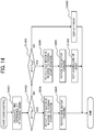
- FIG. 14 is a flowchart of the skew control process. Note that a detailed description of common points with the above-described embodiment is omitted, and differences are mainly described.
- the facing portion 13a according to the variation is different from the above-described embodiment in that the facing portion 13a includes the multiple leading end sensors 16a and 16b.
- the leading end sensors 16a and 16b are disposed facing the outer circumferential surface of the roll 9 at positions separated from each other in the width direction of the continuous sheet P.
- the controller 50 determines the passing times using the respective leading end sensors 16a and 16b in the leading end detection process and the alternative detection process.
- the controller 50 executes the skew control process illustrated in FIG. 14 instead of the processing after step S903 in FIG. 9 .
- a time difference ⁇ T is generated between the passing times determined using the leading end sensors 16a and 16b.
- the controller 50 calculates the time difference ⁇ T (S1401).
- the controller 50 compares the calculated time difference ⁇ T with a first threshold time T th1 and a second threshold time T th2 (S1402 and S1403). Note that the first threshold time T th1 is smaller than the second threshold time T th2 .
- the controller 50 executes the processing in steps S904 and S905.
- the controller 50 executes the processing in steps S904 and S905 and causes the cutter 18 to cut the leading end of the continuous sheet P fed along the guide portion 13b (S1404).
- the controller 50 displays an error on the control panel 57 without executing the processing in steps S904 and S905 (S1405).
- the controller 50 can determine the degree of inclination of the leading end of the continuous sheet P based on the time difference ⁇ T between the passing times.
- the controller 50 stops feeding the continuous sheet P and displays the error.
- the controller 50 can selectively execute desirable one of multiple operations of the sheet feeding device 10 according to the degree of inclination (skew).
- Processing circuitry includes a programmed processor, as a processor includes circuitry.
- a processing circuit also includes devices such as an application specific integrated circuit (ASIC), a digital signal processor (DSP), a field programmable gate array (FPGA), and conventional circuit components arranged to perform the recited functions.
- ASIC application specific integrated circuit
- DSP digital signal processor
- FPGA field programmable gate array
Landscapes
- Controlling Sheets Or Webs (AREA)
Abstract
Description
- Embodiments of the present disclosure relate to a sheet feeding device and an image forming apparatus incorporating the sheet feeding device.
- There is known an image forming apparatus that forms an image on a long sheet (hereinafter, referred to as a "continuous sheet") wound around a spool. The image forming apparatus using the continuous sheet includes a sheet feeding mechanism. A user manually inserts a leading end of the continuous sheet into a sheet feeding portion of the sheet feeding mechanism, and then the image forming apparatus performs a sheet feeding operation after detecting the leading end.
- In such an image forming apparatus, it takes time and effort for the user to manually insert the leading end of the continuous sheet into the sheet feeding portion, and the continuous sheet may be inserted obliquely depending on how the user inserts the leading end, causing skew of the continuous sheet that may require a service call. To solve such a situation, for example,
Japanese Unexamined Patent Application Publication No. 2018-150107 - However, a state of how the leading end is peeled when the spool is reversely rotated changes depending on the thickness, stiffness, and curl of the continuous sheet. Therefore, in the technique in
Japanese Unexamined Patent Application Publication No. 2018-150107 - The present disclosure has been made to solve such a situation, and an object thereof is to provide a technique of stably detecting a leading end of a continuous sheet regardless of the type of the continuous sheet in a sheet feeding device that feeds the continuous sheet wound around a spool.
- Embodiments of the present disclosure describe an improved sheet feeding device that includes a support, a rotation driver, a guide, a support shaft, a biasing member, a sensor, a roller, and circuitry. The support detachably supports a roll formed of a continuous sheet wound around a spool. The rotation driver rotates the spool supported by the support in a feeding direction and a winding direction of the continuous sheet. The guide includes a facing portion that faces an outer circumferential surface of the roll and a guide portion that extends downstream from the facing portion in the feeding direction. The support shaft swingably supports the guide around a downstream end of the guide in the feeding direction, in a direction in which the facing portion contacts and separates from the roll. The biasing member presses the guide in a direction in which the facing portion approaches the roll. The sensor retractably projects from the facing portion toward the roll to contact the roll and outputs a detection signal having a signal level in response to an amount of projection of the sensor. The roller supported by the facing portion contacts the outer circumferential surface of the roll at a different position from the sensor in a circumferential direction of the roll. The circuitry controls the rotation driver based on a signal change rate that is an amount of change in the signal level of the detection signal per unit time. The circuitry causes the rotation driver to rotate the spool in the winding direction to determine a passing time at which a leading end of the continuous sheet passes through the sensor based on a first change rate that is the signal change rate when the senser retracts and a second change rate that is the signal change rate when the sensor projects. Further, the circuitry causes the rotation driver to rotate the spool by a predetermined angle in the winding direction, from the passing time, to position the leading end at a feeding start position that is upstream from the sensor and the roller in the winding direction and facing the guide portion, and causes the rotation driver to rotate the spool in the feeding direction to feed the continuous sheet from the feeding start position along the guide portion.
- As a result, according to the present disclosure, the sheet feeding device feeds the continuous sheet wound around the spool, and can stably detect the leading end of the continuous sheet regardless of the type of the continuous sheet.
- A more complete appreciation of the disclosure and many of the attendant advantages thereof will be readily obtained as the same becomes better understood by reference to the following detailed description when considered in connection with the accompanying drawings, wherein:
-
FIG. 1 is an exterior perspective view of an image forming apparatus according to an embodiment of the present disclosure; -
FIG. 2 is a cross-sectional view illustrating an interior of the image forming apparatus; -
FIG. 3 is a schematic view illustrating a configuration of a sheet feeding device of the image forming apparatus; -
FIG. 4 is a perspective view of a guide arm of the sheet feeding device; -
FIG. 5 is an enlarged view of a facing portion of the guide arm and the surrounding thereof; -
FIGS. 6A to 6C are diagrams illustrating a positional relation between a leading end of a continuous sheet, a leading end sensor, and a roller in the sheet feeding device; -
FIGS. 7A and 7B are diagrams illustrating change of a signal level of a detection signal of the leading end sensor; -
FIG. 8 is a schematic block diagram illustrating a hardware configuration of the image forming apparatus; -
FIG. 9 is a flowchart of a sheet setting process of the sheet feeding device; -
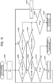
FIG. 10 is a flowchart of a leading end detection process of the sheet feeding device; -
FIG. 11 is a flowchart of an alternative detection process of the sheet feeding device; -
FIG. 12 is a diagram illustrating the change of the signal level of the detection signal in the leading end detection process; -
FIG. 13 is a schematic view illustrating an arrangement of leading end sensors according to a variation of the present disclosure; -
FIG. 14 is a flowchart of a skew control process of the sheet feeding device; and -
FIGS. 15A to 15E are schematic views for explaining a comparative method of setting a rolled sheet. - The accompanying drawings are intended to depict embodiments of the present disclosure and should not be interpreted to limit the scope thereof. The accompanying drawings are not to be considered as drawn to scale unless explicitly noted. In addition, identical or similar reference numerals designate identical or similar components throughout the several views.
- In describing embodiments illustrated in the drawings, specific terminology is employed for the sake of clarity. However, the disclosure of this patent specification is not intended to be limited to the specific terminology so selected, and it is to be understood that each specific element includes all technical equivalents that have the same function, operate in a similar manner, and achieve a similar result.
- As used herein, the singular forms "a", "an", and "the" are intended to include the plural forms as well, unless the context clearly indicates otherwise.
- It is to be noted that the suffixes y, m, c, and k attached to each reference numeral indicate only that components indicated thereby are used for forming yellow, magenta, cyan, and black images, respectively, and hereinafter may be omitted when color discrimination is not necessary.
- Hereinafter, a description is given of an
image forming apparatus 1 according to an embodiment of the present disclosure with reference toFIGS. 1 and2 .FIG. 1 is an exterior perspective view of theimage forming apparatus 1 according to the present embodiment.FIG. 2 is a cross-sectional view illustrating an interior of theimage forming apparatus 1. - As illustrated in
FIG. 1 , a housing of theimage forming apparatus 1 has an exterior constructed of acenter cover 2, aright cover 3 and a left cover 4 disposed on the left and right of thecenter cover 2,side plates 5 disposed at ends of theright cover 3 and the left cover 4, and anoperation cover 6 that opens and closes respect to thecenter cover 2. An apparatus body of theimage forming apparatus 1 covered with therespective covers 2 to 6 is supported by left andright legs 7 with casters. - The
image forming apparatus 1 according to the present embodiment is an image forming apparatus using an inkjet method that discharges ink onto a continuous sheet P (long sheet) to form an image on the continuous sheet P. A method of image formation used by theimage forming apparatus 1 is not limited to the inkjet method, and an electrophotographic method can be used. As illustrated inFIG. 2 , theimage forming apparatus 1 mainly includes asheet feeding device 10, aconveyance unit 20, animage forming unit 30, awinding unit 40, and a controller 50 (seeFIG. 8 ). - The
sheet feeding device 10 feeds the continuous sheet P wound around aspool 8 to theconveyance unit 20 through a conveyance path L. The conveyance path L is a space through which the continuous sheet P passes inside theimage forming apparatus 1. More specifically, the conveyance path L is a route from thesheet feeding device 10 to thewinding unit 40 via theconveyance unit 20 and theimage forming unit 30. Details of thesheet feeding device 10 is described later with reference toFIGS. 3 to 7 . - The
conveyance unit 20 conveys the continuous sheet P, which is fed from thesheet feeding device 10 through the conveyance path L, to thewinding unit 40 through a position facing theimage forming unit 30. Theconveyance unit 20 mainly includes aconveyance roller 21, apressure roller 22, and aconveyance motor 23. Theconveyance roller 21 and thepressure roller 22 rotate while nipping the continuous sheet P from both sides in the direction of thickness of the continuous sheet P. Theconveyance motor 23 transmits a driving force to rotate theconveyance roller 21. Thepressure roller 22 is pressed against theconveyance roller 21 with a predetermined pressure and rotated along with the rotation of theconveyance roller 21. - The
image forming unit 30 is disposed downstream from theconveyance unit 20 in the direction of conveyance of the continuous sheet P. Theimage forming unit 30 discharges ink onto the continuous sheet P conveyed by theconveyance unit 20 to form an image on the continuous sheet P. Theimage forming unit 30 mainly includes acarriage 31, amain scanning motor 32, and aplaten 33. - As the
main scanning motor 32 transmits a driving force, thecarriage 31 reciprocates in the main scanning direction perpendicular to the direction of conveyance of the continuous sheet P. Thecarriage 31 includes recording heads 31k, 31c, 31m, and 31y that discharge inks of respective colors of black, cyan, magenta, and yellow. The recording heads 31k, 31c, 31m, and 31y discharge the inks of the respective colors toward the continuous sheet P supported by theplaten 33 in accordance with instructions from thecontroller 50. Theplaten 33 upwardly faces thecarriage 31. Theplaten 33 supports the continuous sheet P conveyed by theconveyance unit 20. - The winding
unit 40 is disposed downstream from theconveyance unit 20 and theimage forming unit 30 in the direction of conveyance of the continuous sheet P. The windingunit 40 winds the continuous sheet P on which an image has been formed by theimage forming unit 30. The windingunit 40 mainly includes a windingroller 41 and a windingmotor 42. As the windingmotor 42 transmits a driving force, the windingroller 41 rotates to wind the continuous sheet P on which the image has been formed. - Here, a comparative method of setting a rolled sheet is described.
FIGS. 15A to 15E are schematic views for explaining the comparative method of setting the rolled sheet. The rolled sheet is provided with flanges at the ends in a width direction of the rolled sheet, and a spool is set into the rolled sheet. A user sets the rolled sheet with the spool in a sheet holding portion (spool bearing mount) of an apparatus as illustrated inFIG. 15A , searches for a leading end of a continuous sheet of the rolled sheet, holds the rolled sheet with both hands as illustrated inFIG. 15B while keeping an eye on the leading end, and rotates the rolled sheet so that the leading end of the continuous sheet reaches the front side. Next, the user guides the leading end of the continuous sheet between guide plates disposed on the back side of the rolled sheet and inserts the leading end while rotating the rolled sheet as illustrated inFIG. 15C . When the user inserts the leading end of the continuous sheet into the back of the guide plates, the apparatus holds the leading end and pull the continuous sheet therein. - As illustrated in
FIG. 15C , since the guide plates between which the leading end of the continuous sheet is inserted is located on the back side of the rolled sheet, the guide plates are hidden behind the rolled sheet. Accordingly, it is difficult for the user to see the guide plates and confirm whether the leading end has been inserted between the guide plates. In addition, the user is required to insert the leading end of the continuous sheet of the rolled sheet as evenly as possible, which is a delicate operation. If the leading end of the continuous sheet is not inserted evenly, the continuous sheet is fed obliquely, which may cause skew or jam of the continuous sheet, and the user may have to reset the rolled sheet. - Further, as illustrated in
FIGS. 15D and 15E , when the apparatus includes two-stage rolled sheet mounts, if the rolled sheet is set on the upper stage, it is more difficult for the user to see the guide plates and insert the leading end between the guide plates because of the rolled sheet on the upper stage, which may increase the difficulty in setting the rolled sheet and the possibility of oblique insertion. -
FIG. 3 is a schematic view illustrating a configuration of thesheet feeding device 10.FIG. 4 is a perspective view of aguide arm 13 of thesheet feeding device 10. As illustrated inFIGS. 2 to 4 , thesheet feeding device 10 mainly includes asupport 11, afeed motor 12 as a rotation driver, theguide arm 13 as a guide, asupport shaft 14, acoil spring 15 as a biasing member, aleading end sensor 16,multiple rollers cutter 18, and guideplates - The
support 11 detachably supports aroll 9. Theroll 9 is a rolled sheet formed by winding the continuous sheet P around thespool 8 having a shaft shape. More specifically, thesupport 11 rotatably supports both ends of thespool 8. Thefeed motor 12 rotates thespool 8 supported by thesupport 11 forward in the counterclockwise direction inFIG. 3 , that is, in a feeding direction to feed the continuous sheet P from theroll 9, and rotates thespool 8 in reverse in the clockwise direction inFIG. 3 , that is, in a winding direction to wind the continuous sheet P. - The
guide arm 13 brings theleading end sensor 16 and therollers roll 9 and guides the continuous sheet P fed from theroll 9 between theguide plates guide arm 13 has an elongated plate shape. Theguide arm 13 includes a facingportion 13a and aguide portion 13b. - The facing
portion 13a has an arc shape along the outer circumferential surface of theroll 9. The facingportion 13a faces the outer circumferential surface of theroll 9 below a horizontal line passing through the center of rotation of thespool 8. More specifically, the facingportion 13a faces a region (lower region) including the lower end of theroll 9. Theguide portion 13b extends downstream from the facingportion 13a in the feeding direction of the continuous sheet P. More specifically, theguide portion 13b extends from the facingportion 13a to a position between theguide plates - The
support shaft 14 extends in the same direction as the longitudinal direction of thespool 8 supported by thesupport 11. Thesupport shaft 14 is secured inside thecovers 2 to 6. Thesupport shaft 14 is attached to a downstream end of theguide portion 13b in the feeding direction of the continuous sheet P, and swingably supports theguide arm 13. That is, theguide arm 13 is swingable around thesupport shaft 14 so that the facingportion 13a contacts and separates from theroll 9. Thecoil spring 15 presses theguide arm 13 in a direction in which the facingportion 13a approaches theroll 9. - The
leading end sensor 16 projects from the facingportion 13a toward theroll 9. Theleading end sensor 16 is supported by the facingportion 13a and retractable with respect to the facingportion 13a. Further, theleading end sensor 16 is biased in a direction in which theleading end sensor 16 comes into contact with the outer circumferential surface of theroll 9, that is, in a direction in which theleading end sensor 16 projects from the facingportion 13a. Theleading end sensor 16 outputs a detection signal to thecontroller 50. The detection signal has a signal level in response to an amount of projection of theleading end sensor 16 from the facingportion 13a. More specifically, the signal level of the detection signal increases as the amount of projection increases, and decreases as the amount of projection decreases. - The
rollers portion 13a. The axis of rotation of therollers spool 8 and thesupport shaft 14. Therollers leading end sensor 16 in a circumferential direction of theroll 9. More specifically, therollers leading end sensor 16 in the winding direction. Further, therollers roll 9. More specifically, theleading end sensor 16 is disposed between theroller 17a and theroller 17b in the width direction. - The
cutter 18 cuts the leading end of the continuous sheet P over the entire region in the width direction. The cutting line by thecutter 18 extends in the direction perpendicular to the feeding direction of the continuous sheet P. That is, when the leading end of the continuous sheet P is inclined (skewed) with respect to the feeding direction, thecutter 18 cuts the leading end of the continuous sheet P to make the leading end of the continuous sheet P perpendicular to the feeding direction. - The
guide plates guide arm 13 in the feeding direction of the continuous sheet P. Theguide plates guide arm 13, passes between theguide plates conveyance unit 20. That is, theguide plates roll 9 enters. - Next, a description is given of a relation between the position of the leading end of the continuous sheet P and the signal level of the detection signal when the
spool 8 rotates in the winding direction with reference toFIGS. 5 to 7B .FIG. 5 is an enlarged view of the facingportion 13a and the surrounding thereof.FIGS. 6A to 6C are diagrams illustrating a positional relation between the leading end of the continuous sheet P, theleading end sensor 16, and theroller 17a.FIGS. 7A and 7B are diagrams illustrating change of the signal level of the detection signal of theleading end sensor 16. - Since the
guide arm 13 is biased by thecoil spring 15 in the direction in which theguide arm 13 approaches theroll 9, as illustrated inFIG. 5 , theleading end sensor 16 and therollers roll 9. As thespool 8 rotates in the winding direction indicated by arrow WD inFIG. 5 , the leading end of the continuous sheet P that is in close contact with the outer circumferential surface of theroll 9 passes through therollers leading end sensor 16. - As illustrated in
FIGS. 6A and 6B , when the leading end of the continuous sheet P passes through therollers guide arm 13 swings by the thickness of the continuous sheet P, and therollers roll 9. As a result, theleading end sensor 16 is retracted in the facingportion 13a by the thickness of the continuous sheet P. That is, when the leading end of the continuous sheet P passes through therollers leading end sensor 16 decreases. - As a result, as illustrated in
FIG. 7A , the detection signal of theleading end sensor 16 is High signal before the leading end of the continuous sheet P passes through therollers rollers leading end sensor 16 decreases as the leading end of the continuous sheet P passes through therollers - Next, as illustrated in
FIGS. 6B and 6C , when the leading end of the continuous sheet P passes through theleading end sensor 16, theleading end sensor 16 projects from the facingportion 13a by the thickness of the continuous sheet P. That is, when the leading end of the continuous sheet P passes through theleading end sensor 16, the amount of projection of theleading end sensor 16 increases. - As illustrated in
FIG. 7A , the detection signal of theleading end sensor 16 becomes the High signal after the leading end of the continuous sheet P passes through the leading end sensor 16 (region γ). That is, the signal level of the detection signal of theleading end sensor 16 increases as the leading end of the continuous sheet P passes through theleading end sensor 16. - Here, the change in the signal level of the detection signal is microscopically observed in
FIG. 7B . When the leading end of the continuous sheet P passes through therollers leading end sensor 16 decreases by the signal level y1 during the time x1 as illustrated inFIG. 7B . When the leading end of the continuous sheet P passes through theleading end sensor 16, the detection signal of theleading end sensor 16 increases by the signal level y2 during the time x2. - Hereinafter, the amount of change in the signal level of the detection signal per unit time is referred to as a "signal change rate". The signal change rate when the
leading end sensor 16 retracts is referred to as a first change rate, and the signal change rate when theleading end sensor 16 projects is referred to as a second change rate. That is, the first change rate and the second change rate are opposite in the direction of change of the signal level. - The first change rate K1 is defined by expression of K1 = |y1 / x1|. The first change rate K1 exceeds a predetermined first threshold when the leading end of the continuous sheet P passes through the
rollers leading end sensor 16. The first threshold and the second threshold are thresholds for absorbing small variations in the diameter of theroll 9. The first threshold and the second threshold may be the same value or different values. -
FIG. 8 is a schematic block diagram illustrating a hardware configuration of theimage forming apparatus 1. As illustrated inFIG. 8 , theimage forming apparatus 1 includes a central processing unit (CPU) 51 as a control device, a random access memory (RAM) 52 as a storage device, a read only memory (ROM) 53 as a storage device, a hard disk drive (HDD) 54 as a storage device, and an interface (I/F) 55, which are connected via acommon bus 56 as a communication device. TheCPU 51, theRAM 52, theROM 53, and theHDD 54 are examples of thecontroller 50 as circuitry. - The
CPU 51 is an arithmetic device and controls the overall operation of theimage forming apparatus 1. TheRAM 52 is a volatile storage medium in which data is read and written at high speed and used as a working area when theCPU 51 processes data. TheROM 53 is a non-volatile read only storage medium and stores programs such as firmware. TheHDD 54 is a non-volatile storage medium with large storage capacity, in which data is read and written, and stores an operating system (OS), various control programs, application programs, and the like. - The
image forming apparatus 1 processes various programs loaded from theROM 53 or theHDD 54 to theRAM 52 by arithmetic functions provided in theCPU 51. By this processing, a software control unit including various functional modules of theimage forming apparatus 1 is configured. The software control unit thus configured and the hardware resources installed in theimage forming apparatus 1, in combination, construct functional blocks that implement the function of theimage forming apparatus 1. - The I/
F 55 connects thesheet feeding device 10, theconveyance unit 20, theimage forming unit 30, the windingunit 40, and a control panel (input unit) 57 to thecommon bus 56. That is, thecontroller 50 controls thesheet feeding device 10, theconveyance unit 20, theimage forming unit 30, the windingunit 40, and thecontrol panel 57 via the I/F 55. - The
control panel 57 is a user interface including a display that displays various types of information to be indicated to an operator, and buttons, switches, dials, and the like that accept operations by the operator. Thecontrol panel 57 may include a touch panel overlaid on the display. Thecontrol panel 57 accepts the operation by the operator and outputs an operation signal corresponding to the accepted operation to thecontroller 50. - Next, a sheet setting process is described with reference to
FIG. 9. FIG. 9 is a flowchart of the sheet setting process. In the sheet setting process, when anew roll 9 is mounted on thesupport 11, the continuous sheet P of theroll 9 is fed to theconveyance unit 20 through between theguide plates controller 50 controls thefeed motor 12 based on the signal change rate of theleading end sensor 16. The sheet setting process starts, for example, when a sensor detects that theroll 9 is mounted on thesheet feeding device 10 or when thecontrol panel 57 accepts an operation indicating that theroll 9 has been replaced. - First, the
controller 50 rotates thefeed motor 12 in reverse to rotate thespool 8 in the winding direction (S901). In addition, thecontroller 50 executes a leading end detection process described later while rotating thefeed motor 12 in the reverse (S902). Then, thecontroller 50 determines whether the detection of the leading end of the continuous sheet P is successful in the leading end detection process (S903). - When the
controller 50 determines that the detection of the leading end of the continuous sheet P is successful (Yes in S903), thecontroller 50 causes thefeed motor 12 to rotate in reverse to rotate thespool 8 in the winding direction by a predetermined rotation angle (for example, about 355 degrees) from a passing time determined in the leading end detection process (S904). Thus, the leading end of the continuous sheet P reaches a feeding start position. - The passing time indicates when the leading end of the continuous sheet P passes through the
leading end sensor 16. The feeding start position indicates a position upstream from theleading end sensor 16 and therollers guide portion 13b. In other words, the feeding start position is a position where the continuous sheet P is fed toward theguide plates guide portion 13b when thespool 8 rotates in the feeding direction. - Next, the
controller 50 causes thefeed motor 12 to rotate forward to feed the continuous sheet P from the feeding start position along theguide portion 13b (S905). Thus, the continuous sheet P passes between theguide plates conveyance roller 21 and thepressure roller 22. - After finishing the sheet setting process normally, the
image forming apparatus 1 can execute an image forming process to form an image on the continuous sheet P. That is, thecontroller 50 drives theconveyance motor 23 to convey the continuous sheet P to a position facing the recording heads 31k, 31c, 31m, and 31y. Next, thecontroller 50 drives themain scanning motor 32 to move thecarriage 31 in the main scanning direction and causes the recording heads 31k, 31c, 31m, and 31y to discharge ink. By repeating this process, an image is recorded on the continuous sheet P. Further, thecontroller 50 drives the windingmotor 42 to wind the continuous sheet P on which the image is recorded on the windingroller 41. - On the other hand, when the
controller 50 determines that the detection of the leading end of the continuous sheet P fails (No in S903), thecontroller 50 stops thefeed motor 12 and displays an error on the control panel 57 (S906). The operator performs an appropriate operation (for example, remounting of the roll 9) according to the content of the error displayed on thecontrol panel 57. - Next, with reference to
FIGS. 10 to 12 , a description is given of the leading end detection process of detecting the leading end of the continuous sheet P in step S902 illustrated inFIG. 9 .FIG. 10 is a flowchart of the leading end detection process.FIG. 11 is a flowchart of an alternative detection process.FIG. 12 is a diagram illustrating the change of the signal level of the detection signal in the leading end detection process. During the leading end detection process and the alternative detection process, thespool 8 rotates in the winding direction. - In the leading end detection process illustrated in
FIG. 10 , thecontroller 50 determines the passing time based on both the first change rate K1 and the second change rate K2. On the other hand, in the alternative detection process illustrated inFIG. 11 , thecontroller 50 determines the passing time based on only the second change rate K2. In the present embodiment, first, thecontroller 50 determines the passing time in the leading end detection process, and when thecontroller 50 fails to detect the passing time in the leading end detection process, thecontroller 50 executes the alternative detection process. Note that the leading end detection process and the alternative detection process may be performed independently. - First, the
controller 50 initializes variables R and N stored inRAM 52 to 1 (S1001). The variable R represents the number of rotations of thespool 8 in the leading end detection process. The variable N represents the number of times thecontroller 50 determines the passing time in the leading end detection process. - Next, the
controller 50 waits for subsequent processing until the first change rate K1 of the detection signal exceeds the first threshold (S1002) or until the second time t2 elapses (S1003). Thecontroller 50 determines that the leading end of the continuous sheet P has passed through therollers - Next, when the
controller 50 determines that the leading of the continuous sheet P has passed through therollers controller 50 waits for subsequent processing until the second change rate K2 of the detection signal exceeds the second threshold (S1004) or the first time t1 elapses (S1005). When the second change rate K2 exceeds the second threshold (Yes in S1004) before the first time t1 elapses (No in S1005), thecontroller 50 determines that the leading end of the continuous sheet P has passed theleading end sensor 16. - As illustrated in
FIG. 12 , the first time t1 is a predetermined time corresponding to a separation distance between theleading end sensor 16 and therollers roll 9 to rotate by the separation distance with a margin added. The second time t2 is a time required for theroll 9 to make one rotation with a positive margin added. The third time range t3 is a predetermined time range included in the second time t2. Specifically, the third time range t3 is a time range between the timing at which the second time t2 elapses (the end of the second time t2) and a time going back a predetermined time from the end of the second time t2. More specifically, the third time range t3 is a time range including positive and negative margins with respect to the timing at which the leading end of the continuous sheet P is assumed to pass through theleading end sensor 16 in the second time t2. - The
controller 50 determines the timing at which the second change rate K2 exceeds the second threshold (Yes in S 1004) as the passing time until the first time t1 elapses (No in S 1005) after the first change rate K1 exceeds the first threshold (Yes in S 1002). When thecontroller 50 determines the passing time, thecontroller 50 compares the variable N with a determination threshold Xth (S 1006). - Then, when the variable N is less than the determination threshold Xth (No in S 1006), the
controller 50 increments the variable N by 1 (S 1007) and executes the processing from step S1002 again. When the variable N reaches the determination threshold Xth (Yes in S 1006), thecontroller 50 determines that the detection of the leading end of the continuous sheet P is successful and ends the leading end detection process. - That is, when the
controller 50 determines the passing time within the third time range t3 included in each second time of Xth times (Yes in S 1004) while the second time t2 elapses Xth times (No in S1006), thecontroller 50 executes the processing in step S904 at the Xth-th passing time. The determination threshold Xth is a value to determine whether the number of times thecontroller 50 detects the leading end of the continuous sheet P exceeds a predetermined number of times. The determination threshold Xth may be a certain fixed number, or may be a value of N input through thecontrol panel 57. The determination threshold Xth is an integer that may be 1, or 2 or more. - On the other hand, when the second time t2 has elapsed before the first change rate K1 exceeds the first threshold (No in S1002 and Yes in S 1003) or when the first change rate K1 exceeds the first threshold outside the third time range t3, the
controller 50 compares the variable R with a rotation threshold Rth (S 1008). Similarly, when the first time t1 has elapsed (Yes in S 1005) before the second change rate K2 exceeds the second threshold (No in S1004), thecontroller 50 compares the variable R with the rotation threshold Rth (S1008). - Then, when the variable R is less than the rotation threshold Rth (No in S 1008), the
controller 50 increments the variable R by 1 (S 1009) and executes the processing from step S 1002 again. When the variable R reaches the rotation threshold Rth (Yes in S 1008), thecontroller 50 determines that the detection of the leading end of the continuous sheet P in the leading end detection process fails and executes the alternative detection process (S1010). - That is, when the
controller 50 fails to detect the first change rate K1 and the second change rate K2 (No in S1002 and No in S1004) until theroll 9 rotates Rth times in the winding direction (No in S1008), thecontroller 50 executes the alternative detection process (S1010). The rotation threshold Rth is a value to determine whether the number of times thecontroller 50 fails to detect the leading end of the continuous sheet P exceeds a predetermined number of times from the start of the leading end detection process (S1001) to the alternative detection process (S1010). The rotation threshold Rth may be a predetermined fixed number, or may be a value of R input through thecontrol panel 57. The rotation threshold Rth is an integer that may be 1, or 2 or more. - As illustrated in
FIG. 11 , thecontroller 50 initializes variables R and N stored inRAM 52 to 1 (S1101). The definitions of the variables R and N, the determination threshold Xth, and the rotation threshold Rth are the same as the above-described definitions in the leading end detection process. - Next, the
controller 50 waits for subsequent processing until the second change rate K2 of the detection signal exceeds the second threshold (S1102) or until the second time t2 elapses (S1103). Thecontroller 50 determines that the leading end of the continuous sheet P has passed through theleading end sensor 16, that is, the passing time when the second change rate K2 exceeds the second threshold within the predetermined third time range t3 (Yes in S1102) until the second time t2 elapses (No in S1103). - When the
controller 50 determines the passing time (Yes in S1102), thecontroller 50 compares the variable N with the determination threshold Xth (S1104). Then, when the variable N is less than the determination threshold Xth (No in S1104), thecontroller 50 increments the variable N by 1 (S1105) and executes the processing from step S 1102 again. When the variable N reaches the determination threshold Xth (Yes in S1104), thecontroller 50 determines that the detection of the leading end of the continuous sheet P is successful and ends the alternative detection process. That is, when the second change rate K2 exceeds the second threshold within the third time range t3 included in each second time t2 of Xth times while the second time t2 elapses Xth times (No in S1104), thecontroller 50 determines the timing at which the second change rate K2 exceeds the second threshold Xth times as the passing time. - On the other hand, when the second time t2 has elapsed before the second change rate K2 exceeds the second threshold (No in S1102 and Yes in S1103) or when the second change rate K2 exceeds the second threshold outside the third time range t3, the
controller 50 compares the variable R with the rotation threshold Rth (S1106). Then, when the variable R is less than the rotation threshold Rth (No in S1106), thecontroller 50 increments the variable R by 1 (S1107) and executes the processing from step S1102 again. When the variable R reaches the rotation threshold Rth (Yes in S1106), thecontroller 50 determines that the detection of the leading end of the continuous sheet P in the alternative detection process fails and ends the alternative detection process. - According to the above-described embodiment, the following operational effects, for example, are achieved.
- According to the above-described embodiment, the leading end of the continuous sheet P is detected in a state in which the leading end is in close contact with the outer circumferential surface of the
roll 9. Therefore, the leading end of the continuous sheet P can be stably detected regardless of the thickness, stiffness, and curl of the continuous sheet P. As theroll 9 is just mounted on thesupport 11, the leading end is automatically detected and inserted between theguide plates guide plates - Further, according to the above-described embodiment, the
controller 50 determines the timing at which the second change rate K2 exceeds the second threshold as the passing time until the first time t1 elapses after the first change rate K1 exceeds the first threshold. Accordingly, thecontroller 50 does not erroneously detect the unevenness of theroll 9 as the leading end of the continuous sheet P. - Further, according to the above-described embodiment, the
controller 50 repeatedly detects the leading end of the continuous sheet P Xth times, thereby improving the accuracy of detection. Further, the operator can set the determination threshold Xth large when the continuous sheet P is thin, and small when the continuous sheet P is thick, for example. As a result, the accuracy and throughput of the detection are compatible with each other. - When the leading end of the continuous sheet P is inclined with respect to the feeding direction, the first change rate K1 when the leading end of the continuous sheet P passes through the
rollers controller 50 does not appropriately detect the leading end of the continuous sheet P in the leading end detection process, thecontroller 50 executes the alternative detection process. Accordingly, thecontroller 50 can appropriately detect the leading end of the continuous sheet P regardless of the degree of inclination of the continuous sheet P. - A skew control process according to a variation of the present disclosure is described with reference to
FIGS. 13 and14 .FIG. 13 is a schematic view illustrating an arrangement of leadingend sensors FIG. 14 is a flowchart of the skew control process. Note that a detailed description of common points with the above-described embodiment is omitted, and differences are mainly described. - The facing
portion 13a according to the variation is different from the above-described embodiment in that the facingportion 13a includes the multipleleading end sensors leading end sensors roll 9 at positions separated from each other in the width direction of the continuous sheet P. According to the variation, thecontroller 50 determines the passing times using the respectiveleading end sensors controller 50 executes the skew control process illustrated inFIG. 14 instead of the processing after step S903 inFIG. 9 . - As illustrated in
FIG. 13 , when the leading end of the continuous sheet P is inclined with respect to the feeding direction, a time difference ΔT is generated between the passing times determined using theleading end sensors FIG. 14 , when the detection of the leading end of the continuous sheet P is successful (Yes in S903), thecontroller 50 calculates the time difference ΔT (S1401). Next, thecontroller 50 compares the calculated time difference ΔT with a first threshold time Tth1 and a second threshold time Tth2 (S1402 and S1403). Note that the first threshold time Tth1 is smaller than the second threshold time Tth2. - When the time difference ΔT is less than the first threshold time Tth1 (Yes in S1402), the
controller 50 executes the processing in steps S904 and S905. When the time difference ΔT is equal to or greater than the first threshold time Tth1 and less than the second threshold time Tth2 (No in S1402 and Yes in S 1403), thecontroller 50 executes the processing in steps S904 and S905 and causes thecutter 18 to cut the leading end of the continuous sheet P fed along theguide portion 13b (S1404). Further, when the time difference ΔT is equal to or greater than the second threshold time Tth2 (No in S1402 and No in S 1403), thecontroller 50 displays an error on thecontrol panel 57 without executing the processing in steps S904 and S905 (S1405). - As described in the above variation, since the
leading end sensors controller 50 can determine the degree of inclination of the leading end of the continuous sheet P based on the time difference ΔT between the passing times. According to the above variation, when the time difference ΔT is large to some extent (the skew is not so large), the leading end is cut by thecutter 18, and when the time difference ΔT is very large (the skew is large), thecontroller 50 stops feeding the continuous sheet P and displays the error. Thus, thecontroller 50 can selectively execute desirable one of multiple operations of thesheet feeding device 10 according to the degree of inclination (skew). - Any one of the above-described operations may be performed in various other ways, for example, in an order different from the one described above. Each of the functions of the described embodiments may be implemented by one or more processing circuits or circuitry. Processing circuitry includes a programmed processor, as a processor includes circuitry. A processing circuit also includes devices such as an application specific integrated circuit (ASIC), a digital signal processor (DSP), a field programmable gate array (FPGA), and conventional circuit components arranged to perform the recited functions.
Claims (9)
- A sheet feeding device (10) comprising:a support (11) configured to detachably support a roll (9) formed of a continuous sheet (P) wound around a spool (8);a rotation driver (12) configured to rotate the spool (8) supported by the support (11) in a feeding direction and a winding direction of the continuous sheet (P);a guide (13) including:a facing portion (13a) configured to face an outer circumferential surface of the roll (9); anda guide portion (13b) extending downstream from the facing portion (13a) in the feeding direction;a support shaft (14) configured to swingably support the guide (13) around a downstream end of the guide (13) in the feeding direction, in a direction in which the facing portion (13a) contacts and separates from the roll (9);a biasing member (15) configured to press the guide (13) in a direction in which the facing portion (13a) approaches the roll (9);a sensor (16) configured to:retractably project from the facing portion (13a) toward the roll (9) to contact the outer circumferential surface of the roll (9); andoutput a detection signal having a signal level in response to an amount of projection of the sensor (16);a roller (17a; 17b) supported by the facing portion (13a), the roller (17a; 17b) configured to contact the outer circumferential surface of the roll (9) at a different position from the sensor (16) in a circumferential direction of the roll (9); andcircuitry (50) configured to:control the rotation driver (12) based on a signal change rate that is an amount of change in the signal level of the detection signal per unit time;cause the rotation driver (12) to rotate the spool (8) in the winding direction to determine a passing time at which a leading end of the continuous sheet (P) passes through the sensor (16) based on a first change rate (K1) that is the signal change rate when the senser (16) retracts and a second change rate (K2) that is the signal change rate when the sensor (16) projects;cause the rotation driver (12) to rotate the spool (8) by a predetermined angle in the winding direction, from the passing time, to position the leading end at a feeding start position that is upstream from the sensor (16) and the roller (17a; 17b) in the winding direction and facing the guide portion (13b); andcause the rotation driver (12) to rotate the spool (8) in the feeding direction to feed the continuous sheet (P) from the feeding start position along the guide portion (13b).
- The sheet feeding device (10) according to claim 1,
wherein the roller (17a; 17b) is disposed upstream from the sensor (16) in the winding direction, and
wherein the circuitry (50) is configured to determine, as the passing time, a timing at which the second change rate (K2) exceeds a second threshold until a first time (t1) elapses after the first change rate (K1) exceeds a first threshold, the first time (t1) corresponding to a distance between the roller (17a; 17b) and the sensor (16). - The sheet feeding device (10) according to claim 2,
wherein, when a second time (t2) corresponding to one rotation of the roll (9) elapses Xth times, and the circuitry (50) determines the passing time to be within a third time range (t3) included in the second time (t2) in each time of the Xth times, the circuitry (50) causes the rotation driver (12) to rotate the spool (8) by the predetermined angle in the winding direction from Xth-th passing time, where Xth is an integer greater than or equal to 2. - The sheet feeding device (10) according to any one of claims 1 to 3,
wherein, when the circuitry (50) fails to detect the first change rate (K1) until the roll (9) rotates Rth times in the winding direction, the circuitry (50) determines the passing time based on the second change rate (K1), where Rth is an integer greater than or equal to 1. - The sheet feeding device (10) according to claim 4,
wherein, when a second time (t2) corresponding to one rotation of the roll (9) elapses Xth times, and the second change rate (K2) exceeds a second threshold within a third time range (t3) included in the second time (t2) in each time of the Xth times, the circuitry (50) determines, as the passing time, a timing at which the second change rate (K2) exceeds the second threshold Xth times, where Xth is an integer greater than or equal to 2. - The sheet feeding device (10) according to claim 3 or 5, further comprising an input unit (57) configured to accept an operation of inputting a value of Xth.
- The sheet feeding device (10) according to any one of claims 1 to 6,
wherein the sensor (16) includes multiple sensors (16a; 16b) disposed separately from each other in a width direction of the continuous sheet (P). - The sheet feeding device (10) according to claim 7,
wherein the circuitry (50) is configured to execute any one of multiple operations based on a time difference (ΔT) between the passing times determined using the multiple sensors (16a; 16b). - An image forming apparatus (1) comprising:the sheet feeding device (10) according to any one of claims 1 to 8, configured to feed the continuous sheet (P); andan image forming unit (30) configured to form an image on the continuous sheet (P).
Applications Claiming Priority (2)
| Application Number | Priority Date | Filing Date | Title |
|---|---|---|---|
| JP2020091640 | 2020-05-26 | ||
| JP2021082233A JP7613255B2 (en) | 2020-05-26 | 2021-05-14 | Sheet feeding device and image forming apparatus |
Publications (2)
| Publication Number | Publication Date |
|---|---|
| EP3915794A1 true EP3915794A1 (en) | 2021-12-01 |
| EP3915794B1 EP3915794B1 (en) | 2023-03-01 |
Family
ID=76444220
Family Applications (1)
| Application Number | Title | Priority Date | Filing Date |
|---|---|---|---|
| EP21175500.4A Active EP3915794B1 (en) | 2020-05-26 | 2021-05-24 | Sheet feeding device and image forming apparatus incorporating same |
Country Status (2)
| Country | Link |
|---|---|
| US (1) | US11613137B2 (en) |
| EP (1) | EP3915794B1 (en) |
Families Citing this family (5)
| Publication number | Priority date | Publication date | Assignee | Title |
|---|---|---|---|---|
| JP7771702B2 (en) | 2021-12-10 | 2025-11-18 | 株式会社リコー | Sheet conveying device and image forming apparatus |
| JP7767974B2 (en) * | 2022-02-18 | 2025-11-12 | 株式会社リコー | Paper feeder and image forming apparatus |
| JP7831006B2 (en) * | 2022-02-28 | 2026-03-17 | 株式会社リコー | Sheet supply device and image forming apparatus |
| JP2024056220A (en) * | 2022-10-11 | 2024-04-23 | 株式会社リコー | Paper feeder and image forming apparatus |
| JP2024134018A (en) | 2023-03-20 | 2024-10-03 | 株式会社リコー | Paper feeder and image forming apparatus |
Citations (4)
| Publication number | Priority date | Publication date | Assignee | Title |
|---|---|---|---|---|
| US20130221054A1 (en) * | 2012-02-24 | 2013-08-29 | Ricoh Company, Ltd. | Sheet feeder and image forming apparatus including same |
| US20180257892A1 (en) * | 2017-03-10 | 2018-09-13 | Canon Kabushiki Kaisha | Printing apparatus |
| JP2018150108A (en) * | 2017-03-10 | 2018-09-27 | キヤノン株式会社 | Sheet feeding device and printing device |
| US20200130386A1 (en) * | 2018-10-29 | 2020-04-30 | Canon Kabushiki Kaisha | Print apparatus |
Family Cites Families (2)
| Publication number | Priority date | Publication date | Assignee | Title |
|---|---|---|---|---|
| JPH07256964A (en) * | 1994-03-23 | 1995-10-09 | Seiko Epson Corp | Paper guide device for printer |
| JP2018150114A (en) | 2017-03-10 | 2018-09-27 | キヤノン株式会社 | Sheet feeding apparatus and printing apparatus |
-
2021
- 2021-05-24 EP EP21175500.4A patent/EP3915794B1/en active Active
- 2021-05-24 US US17/328,340 patent/US11613137B2/en active Active
Patent Citations (5)
| Publication number | Priority date | Publication date | Assignee | Title |
|---|---|---|---|---|
| US20130221054A1 (en) * | 2012-02-24 | 2013-08-29 | Ricoh Company, Ltd. | Sheet feeder and image forming apparatus including same |
| US20180257892A1 (en) * | 2017-03-10 | 2018-09-13 | Canon Kabushiki Kaisha | Printing apparatus |
| JP2018150107A (en) | 2017-03-10 | 2018-09-27 | キヤノン株式会社 | Sheet feeding device, printing device and jam detection method |
| JP2018150108A (en) * | 2017-03-10 | 2018-09-27 | キヤノン株式会社 | Sheet feeding device and printing device |
| US20200130386A1 (en) * | 2018-10-29 | 2020-04-30 | Canon Kabushiki Kaisha | Print apparatus |
Also Published As
| Publication number | Publication date |
|---|---|
| US11613137B2 (en) | 2023-03-28 |
| US20210370693A1 (en) | 2021-12-02 |
| EP3915794B1 (en) | 2023-03-01 |
Similar Documents
| Publication | Publication Date | Title |
|---|---|---|
| EP3915794B1 (en) | Sheet feeding device and image forming apparatus incorporating same | |
| EP3915793B1 (en) | Sheet feeding device and image forming apparatus incorporating same | |
| US8714541B2 (en) | Image recording apparatus and control method thereof | |
| US11667138B2 (en) | Printing apparatus, control method, and non-transitory computer-readable storage medium | |
| US12157299B2 (en) | Printing apparatus, printing method, and non-transitory computer-readable storage medium | |
| EP3521044B1 (en) | Image printing apparatus and control method therefor | |
| JP7613255B2 (en) | Sheet feeding device and image forming apparatus | |
| US20230286296A1 (en) | Image recording apparatus | |
| US20190180265A1 (en) | Printer and merchandise information processing apparatus | |
| US12522461B2 (en) | Sheet supply device and image forming apparatus | |
| US8146917B2 (en) | Conveying device with roller separating unit | |
| US20130134658A1 (en) | Medium supply device and image forming apparatus | |
| JP5984408B2 (en) | Printer device | |
| JPH0764101B2 (en) | Line feed method and single-cut set device in printer | |
| GB2592467A (en) | Printing apparatus and control method | |
| US12528302B2 (en) | Image forming apparatus and medium abnormality detection method | |
| JP6149464B2 (en) | Sheet feeding apparatus and image recording apparatus | |
| JP2607954B2 (en) | Sheet feeding device | |
| JP2006198859A (en) | Recording apparatus and recording apparatus control method | |
| US20210300085A1 (en) | Printing device having cutting unit for separating printing medium into first and second media, and accommodating unit for accommodating therein second medium | |
| JP3170115B2 (en) | Impact printer | |
| US20100230894A1 (en) | Printing apparatus | |
| JP3466820B2 (en) | Recording medium transport device | |
| JP2012051299A (en) | Printer, information processing apparatus, and program | |
| JPS63102963A (en) | printer |
Legal Events
| Date | Code | Title | Description |
|---|---|---|---|
| PUAI | Public reference made under article 153(3) epc to a published international application that has entered the european phase |
Free format text: ORIGINAL CODE: 0009012 |
|
| STAA | Information on the status of an ep patent application or granted ep patent |
Free format text: STATUS: REQUEST FOR EXAMINATION WAS MADE |
|
| 17P | Request for examination filed |
Effective date: 20210524 |
|
| AK | Designated contracting states |
Kind code of ref document: A1 Designated state(s): AL AT BE BG CH CY CZ DE DK EE ES FI FR GB GR HR HU IE IS IT LI LT LU LV MC MK MT NL NO PL PT RO RS SE SI SK SM TR |
|
| B565 | Issuance of search results under rule 164(2) epc |
Effective date: 20211015 |
|
| GRAP | Despatch of communication of intention to grant a patent |
Free format text: ORIGINAL CODE: EPIDOSNIGR1 |
|
| STAA | Information on the status of an ep patent application or granted ep patent |
Free format text: STATUS: GRANT OF PATENT IS INTENDED |
|
| RIC1 | Information provided on ipc code assigned before grant |
Ipc: B65H 16/10 20060101ALI20221031BHEP Ipc: B41J 15/18 20060101ALI20221031BHEP Ipc: B41J 15/04 20060101ALI20221031BHEP Ipc: B41J 11/00 20060101AFI20221031BHEP |
|
| INTG | Intention to grant announced |
Effective date: 20221128 |
|
| GRAS | Grant fee paid |
Free format text: ORIGINAL CODE: EPIDOSNIGR3 |
|
| GRAA | (expected) grant |
Free format text: ORIGINAL CODE: 0009210 |
|
| STAA | Information on the status of an ep patent application or granted ep patent |
Free format text: STATUS: THE PATENT HAS BEEN GRANTED |
|
| AK | Designated contracting states |
Kind code of ref document: B1 Designated state(s): AL AT BE BG CH CY CZ DE DK EE ES FI FR GB GR HR HU IE IS IT LI LT LU LV MC MK MT NL NO PL PT RO RS SE SI SK SM TR |
|
| REG | Reference to a national code |
Ref country code: GB Ref legal event code: FG4D |
|
| REG | Reference to a national code |
Ref country code: CH Ref legal event code: EP Ref country code: AT Ref legal event code: REF Ref document number: 1550724 Country of ref document: AT Kind code of ref document: T Effective date: 20230315 |
|
| REG | Reference to a national code |
Ref country code: DE Ref legal event code: R096 Ref document number: 602021001496 Country of ref document: DE |
|
| REG | Reference to a national code |
Ref country code: IE Ref legal event code: FG4D |
|
| REG | Reference to a national code |
Ref country code: NL Ref legal event code: FP |
|
| REG | Reference to a national code |
Ref country code: LT Ref legal event code: MG9D |
|
| PG25 | Lapsed in a contracting state [announced via postgrant information from national office to epo] |
Ref country code: RS Free format text: LAPSE BECAUSE OF FAILURE TO SUBMIT A TRANSLATION OF THE DESCRIPTION OR TO PAY THE FEE WITHIN THE PRESCRIBED TIME-LIMIT Effective date: 20230301 Ref country code: NO Free format text: LAPSE BECAUSE OF FAILURE TO SUBMIT A TRANSLATION OF THE DESCRIPTION OR TO PAY THE FEE WITHIN THE PRESCRIBED TIME-LIMIT Effective date: 20230601 Ref country code: LV Free format text: LAPSE BECAUSE OF FAILURE TO SUBMIT A TRANSLATION OF THE DESCRIPTION OR TO PAY THE FEE WITHIN THE PRESCRIBED TIME-LIMIT Effective date: 20230301 Ref country code: LT Free format text: LAPSE BECAUSE OF FAILURE TO SUBMIT A TRANSLATION OF THE DESCRIPTION OR TO PAY THE FEE WITHIN THE PRESCRIBED TIME-LIMIT Effective date: 20230301 Ref country code: HR Free format text: LAPSE BECAUSE OF FAILURE TO SUBMIT A TRANSLATION OF THE DESCRIPTION OR TO PAY THE FEE WITHIN THE PRESCRIBED TIME-LIMIT Effective date: 20230301 Ref country code: ES Free format text: LAPSE BECAUSE OF FAILURE TO SUBMIT A TRANSLATION OF THE DESCRIPTION OR TO PAY THE FEE WITHIN THE PRESCRIBED TIME-LIMIT Effective date: 20230301 |
|
| REG | Reference to a national code |
Ref country code: AT Ref legal event code: MK05 Ref document number: 1550724 Country of ref document: AT Kind code of ref document: T Effective date: 20230301 |
|
| P01 | Opt-out of the competence of the unified patent court (upc) registered |
Effective date: 20230714 |
|
| PG25 | Lapsed in a contracting state [announced via postgrant information from national office to epo] |
Ref country code: SE Free format text: LAPSE BECAUSE OF FAILURE TO SUBMIT A TRANSLATION OF THE DESCRIPTION OR TO PAY THE FEE WITHIN THE PRESCRIBED TIME-LIMIT Effective date: 20230301 Ref country code: PL Free format text: LAPSE BECAUSE OF FAILURE TO SUBMIT A TRANSLATION OF THE DESCRIPTION OR TO PAY THE FEE WITHIN THE PRESCRIBED TIME-LIMIT Effective date: 20230301 Ref country code: GR Free format text: LAPSE BECAUSE OF FAILURE TO SUBMIT A TRANSLATION OF THE DESCRIPTION OR TO PAY THE FEE WITHIN THE PRESCRIBED TIME-LIMIT Effective date: 20230602 Ref country code: FI Free format text: LAPSE BECAUSE OF FAILURE TO SUBMIT A TRANSLATION OF THE DESCRIPTION OR TO PAY THE FEE WITHIN THE PRESCRIBED TIME-LIMIT Effective date: 20230301 |
|
| PG25 | Lapsed in a contracting state [announced via postgrant information from national office to epo] |
Ref country code: SM Free format text: LAPSE BECAUSE OF FAILURE TO SUBMIT A TRANSLATION OF THE DESCRIPTION OR TO PAY THE FEE WITHIN THE PRESCRIBED TIME-LIMIT Effective date: 20230301 Ref country code: RO Free format text: LAPSE BECAUSE OF FAILURE TO SUBMIT A TRANSLATION OF THE DESCRIPTION OR TO PAY THE FEE WITHIN THE PRESCRIBED TIME-LIMIT Effective date: 20230301 Ref country code: PT Free format text: LAPSE BECAUSE OF FAILURE TO SUBMIT A TRANSLATION OF THE DESCRIPTION OR TO PAY THE FEE WITHIN THE PRESCRIBED TIME-LIMIT Effective date: 20230703 Ref country code: EE Free format text: LAPSE BECAUSE OF FAILURE TO SUBMIT A TRANSLATION OF THE DESCRIPTION OR TO PAY THE FEE WITHIN THE PRESCRIBED TIME-LIMIT Effective date: 20230301 Ref country code: CZ Free format text: LAPSE BECAUSE OF FAILURE TO SUBMIT A TRANSLATION OF THE DESCRIPTION OR TO PAY THE FEE WITHIN THE PRESCRIBED TIME-LIMIT Effective date: 20230301 Ref country code: AT Free format text: LAPSE BECAUSE OF FAILURE TO SUBMIT A TRANSLATION OF THE DESCRIPTION OR TO PAY THE FEE WITHIN THE PRESCRIBED TIME-LIMIT Effective date: 20230301 |
|
| PG25 | Lapsed in a contracting state [announced via postgrant information from national office to epo] |
Ref country code: SK Free format text: LAPSE BECAUSE OF FAILURE TO SUBMIT A TRANSLATION OF THE DESCRIPTION OR TO PAY THE FEE WITHIN THE PRESCRIBED TIME-LIMIT Effective date: 20230301 Ref country code: IS Free format text: LAPSE BECAUSE OF FAILURE TO SUBMIT A TRANSLATION OF THE DESCRIPTION OR TO PAY THE FEE WITHIN THE PRESCRIBED TIME-LIMIT Effective date: 20230701 |
|
| REG | Reference to a national code |
Ref country code: DE Ref legal event code: R097 Ref document number: 602021001496 Country of ref document: DE |
|
| PLBE | No opposition filed within time limit |
Free format text: ORIGINAL CODE: 0009261 |
|
| STAA | Information on the status of an ep patent application or granted ep patent |
Free format text: STATUS: NO OPPOSITION FILED WITHIN TIME LIMIT |
|
| PG25 | Lapsed in a contracting state [announced via postgrant information from national office to epo] |
Ref country code: MC Free format text: LAPSE BECAUSE OF FAILURE TO SUBMIT A TRANSLATION OF THE DESCRIPTION OR TO PAY THE FEE WITHIN THE PRESCRIBED TIME-LIMIT Effective date: 20230301 |
|
| REG | Reference to a national code |
Ref country code: BE Ref legal event code: MM Effective date: 20230531 |
|
| PG25 | Lapsed in a contracting state [announced via postgrant information from national office to epo] |
Ref country code: SI Free format text: LAPSE BECAUSE OF FAILURE TO SUBMIT A TRANSLATION OF THE DESCRIPTION OR TO PAY THE FEE WITHIN THE PRESCRIBED TIME-LIMIT Effective date: 20230301 Ref country code: MC Free format text: LAPSE BECAUSE OF FAILURE TO SUBMIT A TRANSLATION OF THE DESCRIPTION OR TO PAY THE FEE WITHIN THE PRESCRIBED TIME-LIMIT Effective date: 20230301 Ref country code: LU Free format text: LAPSE BECAUSE OF NON-PAYMENT OF DUE FEES Effective date: 20230524 Ref country code: DK Free format text: LAPSE BECAUSE OF FAILURE TO SUBMIT A TRANSLATION OF THE DESCRIPTION OR TO PAY THE FEE WITHIN THE PRESCRIBED TIME-LIMIT Effective date: 20230301 |
|
| 26N | No opposition filed |
Effective date: 20231204 |
|
| REG | Reference to a national code |
Ref country code: IE Ref legal event code: MM4A |
|
| PG25 | Lapsed in a contracting state [announced via postgrant information from national office to epo] |
Ref country code: IE Free format text: LAPSE BECAUSE OF NON-PAYMENT OF DUE FEES Effective date: 20230524 |
|
| PG25 | Lapsed in a contracting state [announced via postgrant information from national office to epo] |
Ref country code: IE Free format text: LAPSE BECAUSE OF NON-PAYMENT OF DUE FEES Effective date: 20230524 |
|
| PG25 | Lapsed in a contracting state [announced via postgrant information from national office to epo] |
Ref country code: IT Free format text: LAPSE BECAUSE OF FAILURE TO SUBMIT A TRANSLATION OF THE DESCRIPTION OR TO PAY THE FEE WITHIN THE PRESCRIBED TIME-LIMIT Effective date: 20230301 Ref country code: BE Free format text: LAPSE BECAUSE OF NON-PAYMENT OF DUE FEES Effective date: 20230531 |
|
| PG25 | Lapsed in a contracting state [announced via postgrant information from national office to epo] |
Ref country code: BG Free format text: LAPSE BECAUSE OF FAILURE TO SUBMIT A TRANSLATION OF THE DESCRIPTION OR TO PAY THE FEE WITHIN THE PRESCRIBED TIME-LIMIT Effective date: 20230301 |
|
| PG25 | Lapsed in a contracting state [announced via postgrant information from national office to epo] |
Ref country code: BG Free format text: LAPSE BECAUSE OF FAILURE TO SUBMIT A TRANSLATION OF THE DESCRIPTION OR TO PAY THE FEE WITHIN THE PRESCRIBED TIME-LIMIT Effective date: 20230301 |
|
| REG | Reference to a national code |
Ref country code: CH Ref legal event code: PL |
|
| PG25 | Lapsed in a contracting state [announced via postgrant information from national office to epo] |
Ref country code: CH Free format text: LAPSE BECAUSE OF NON-PAYMENT OF DUE FEES Effective date: 20240531 |
|
| PGFP | Annual fee paid to national office [announced via postgrant information from national office to epo] |
Ref country code: NL Payment date: 20250521 Year of fee payment: 5 |
|
| PGFP | Annual fee paid to national office [announced via postgrant information from national office to epo] |
Ref country code: DE Payment date: 20250521 Year of fee payment: 5 |
|
| PGFP | Annual fee paid to national office [announced via postgrant information from national office to epo] |
Ref country code: GB Payment date: 20250527 Year of fee payment: 5 |
|
| PGFP | Annual fee paid to national office [announced via postgrant information from national office to epo] |
Ref country code: FR Payment date: 20250528 Year of fee payment: 5 |
|
| PG25 | Lapsed in a contracting state [announced via postgrant information from national office to epo] |
Ref country code: CY Free format text: LAPSE BECAUSE OF FAILURE TO SUBMIT A TRANSLATION OF THE DESCRIPTION OR TO PAY THE FEE WITHIN THE PRESCRIBED TIME-LIMIT; INVALID AB INITIO Effective date: 20210524 |
|
| PG25 | Lapsed in a contracting state [announced via postgrant information from national office to epo] |
Ref country code: HU Free format text: LAPSE BECAUSE OF FAILURE TO SUBMIT A TRANSLATION OF THE DESCRIPTION OR TO PAY THE FEE WITHIN THE PRESCRIBED TIME-LIMIT; INVALID AB INITIO Effective date: 20210524 |
|
| PG25 | Lapsed in a contracting state [announced via postgrant information from national office to epo] |
Ref country code: TR Free format text: LAPSE BECAUSE OF FAILURE TO SUBMIT A TRANSLATION OF THE DESCRIPTION OR TO PAY THE FEE WITHIN THE PRESCRIBED TIME-LIMIT Effective date: 20230301 |