EP3915761A1 - Plastic container and method for producing same - Google Patents
Plastic container and method for producing same Download PDFInfo
- Publication number
- EP3915761A1 EP3915761A1 EP20744722.8A EP20744722A EP3915761A1 EP 3915761 A1 EP3915761 A1 EP 3915761A1 EP 20744722 A EP20744722 A EP 20744722A EP 3915761 A1 EP3915761 A1 EP 3915761A1
- Authority
- EP
- European Patent Office
- Prior art keywords
- plastic container
- particles
- filler particles
- innermost layer
- resin
- Prior art date
- Legal status (The legal status is an assumption and is not a legal conclusion. Google has not performed a legal analysis and makes no representation as to the accuracy of the status listed.)
- Granted
Links
Images


Classifications
-
- B—PERFORMING OPERATIONS; TRANSPORTING
- B65—CONVEYING; PACKING; STORING; HANDLING THIN OR FILAMENTARY MATERIAL
- B65D—CONTAINERS FOR STORAGE OR TRANSPORT OF ARTICLES OR MATERIALS, e.g. BAGS, BARRELS, BOTTLES, BOXES, CANS, CARTONS, CRATES, DRUMS, JARS, TANKS, HOPPERS, FORWARDING CONTAINERS; ACCESSORIES, CLOSURES, OR FITTINGS THEREFOR; PACKAGING ELEMENTS; PACKAGES
- B65D1/00—Rigid or semi-rigid containers having bodies formed in one piece, e.g. by casting metallic material, by moulding plastics, by blowing vitreous material, by throwing ceramic material, by moulding pulped fibrous material or by deep-drawing operations performed on sheet material
- B65D1/02—Bottles or similar containers with necks or like restricted apertures, designed for pouring contents
- B65D1/0207—Bottles or similar containers with necks or like restricted apertures, designed for pouring contents characterised by material, e.g. composition, physical features
- B65D1/0215—Bottles or similar containers with necks or like restricted apertures, designed for pouring contents characterised by material, e.g. composition, physical features multilayered
-
- B—PERFORMING OPERATIONS; TRANSPORTING
- B29—WORKING OF PLASTICS; WORKING OF SUBSTANCES IN A PLASTIC STATE IN GENERAL
- B29C—SHAPING OR JOINING OF PLASTICS; SHAPING OF MATERIAL IN A PLASTIC STATE, NOT OTHERWISE PROVIDED FOR; AFTER-TREATMENT OF THE SHAPED PRODUCTS, e.g. REPAIRING
- B29C49/00—Blow-moulding, i.e. blowing a preform or parison to a desired shape within a mould; Apparatus therefor
- B29C49/0005—Blow-moulding, i.e. blowing a preform or parison to a desired shape within a mould; Apparatus therefor characterised by the material
-
- B—PERFORMING OPERATIONS; TRANSPORTING
- B29—WORKING OF PLASTICS; WORKING OF SUBSTANCES IN A PLASTIC STATE IN GENERAL
- B29C—SHAPING OR JOINING OF PLASTICS; SHAPING OF MATERIAL IN A PLASTIC STATE, NOT OTHERWISE PROVIDED FOR; AFTER-TREATMENT OF THE SHAPED PRODUCTS, e.g. REPAIRING
- B29C49/00—Blow-moulding, i.e. blowing a preform or parison to a desired shape within a mould; Apparatus therefor
- B29C49/22—Blow-moulding, i.e. blowing a preform or parison to a desired shape within a mould; Apparatus therefor using multilayered preforms or parisons
-
- B—PERFORMING OPERATIONS; TRANSPORTING
- B65—CONVEYING; PACKING; STORING; HANDLING THIN OR FILAMENTARY MATERIAL
- B65D—CONTAINERS FOR STORAGE OR TRANSPORT OF ARTICLES OR MATERIALS, e.g. BAGS, BARRELS, BOTTLES, BOXES, CANS, CARTONS, CRATES, DRUMS, JARS, TANKS, HOPPERS, FORWARDING CONTAINERS; ACCESSORIES, CLOSURES, OR FITTINGS THEREFOR; PACKAGING ELEMENTS; PACKAGES
- B65D1/00—Rigid or semi-rigid containers having bodies formed in one piece, e.g. by casting metallic material, by moulding plastics, by blowing vitreous material, by throwing ceramic material, by moulding pulped fibrous material or by deep-drawing operations performed on sheet material
- B65D1/40—Details of walls
-
- B—PERFORMING OPERATIONS; TRANSPORTING
- B65—CONVEYING; PACKING; STORING; HANDLING THIN OR FILAMENTARY MATERIAL
- B65D—CONTAINERS FOR STORAGE OR TRANSPORT OF ARTICLES OR MATERIALS, e.g. BAGS, BARRELS, BOTTLES, BOXES, CANS, CARTONS, CRATES, DRUMS, JARS, TANKS, HOPPERS, FORWARDING CONTAINERS; ACCESSORIES, CLOSURES, OR FITTINGS THEREFOR; PACKAGING ELEMENTS; PACKAGES
- B65D23/00—Details of bottles or jars not otherwise provided for
- B65D23/02—Linings or internal coatings
-
- B—PERFORMING OPERATIONS; TRANSPORTING
- B65—CONVEYING; PACKING; STORING; HANDLING THIN OR FILAMENTARY MATERIAL
- B65D—CONTAINERS FOR STORAGE OR TRANSPORT OF ARTICLES OR MATERIALS, e.g. BAGS, BARRELS, BOTTLES, BOXES, CANS, CARTONS, CRATES, DRUMS, JARS, TANKS, HOPPERS, FORWARDING CONTAINERS; ACCESSORIES, CLOSURES, OR FITTINGS THEREFOR; PACKAGING ELEMENTS; PACKAGES
- B65D23/00—Details of bottles or jars not otherwise provided for
- B65D23/04—Means for mixing or for promoting flow of contents
-
- B—PERFORMING OPERATIONS; TRANSPORTING
- B29—WORKING OF PLASTICS; WORKING OF SUBSTANCES IN A PLASTIC STATE IN GENERAL
- B29K—INDEXING SCHEME ASSOCIATED WITH SUBCLASSES B29B, B29C OR B29D, RELATING TO MOULDING MATERIALS OR TO MATERIALS FOR MOULDS, REINFORCEMENTS, FILLERS OR PREFORMED PARTS, e.g. INSERTS
- B29K2023/00—Use of polyalkenes or derivatives thereof as moulding material
- B29K2023/10—Polymers of propylene
- B29K2023/12—PP, i.e. polypropylene
-
- B—PERFORMING OPERATIONS; TRANSPORTING
- B29—WORKING OF PLASTICS; WORKING OF SUBSTANCES IN A PLASTIC STATE IN GENERAL
- B29K—INDEXING SCHEME ASSOCIATED WITH SUBCLASSES B29B, B29C OR B29D, RELATING TO MOULDING MATERIALS OR TO MATERIALS FOR MOULDS, REINFORCEMENTS, FILLERS OR PREFORMED PARTS, e.g. INSERTS
- B29K2105/00—Condition, form or state of moulded material or of the material to be shaped
- B29K2105/0005—Condition, form or state of moulded material or of the material to be shaped containing compounding ingredients
-
- B—PERFORMING OPERATIONS; TRANSPORTING
- B29—WORKING OF PLASTICS; WORKING OF SUBSTANCES IN A PLASTIC STATE IN GENERAL
- B29K—INDEXING SCHEME ASSOCIATED WITH SUBCLASSES B29B, B29C OR B29D, RELATING TO MOULDING MATERIALS OR TO MATERIALS FOR MOULDS, REINFORCEMENTS, FILLERS OR PREFORMED PARTS, e.g. INSERTS
- B29K2505/00—Use of metals, their alloys or their compounds, as filler
-
- B—PERFORMING OPERATIONS; TRANSPORTING
- B29—WORKING OF PLASTICS; WORKING OF SUBSTANCES IN A PLASTIC STATE IN GENERAL
- B29L—INDEXING SCHEME ASSOCIATED WITH SUBCLASS B29C, RELATING TO PARTICULAR ARTICLES
- B29L2023/00—Tubular articles
- B29L2023/003—Tubular articles having irregular or rough surfaces
-
- B—PERFORMING OPERATIONS; TRANSPORTING
- B29—WORKING OF PLASTICS; WORKING OF SUBSTANCES IN A PLASTIC STATE IN GENERAL
- B29L—INDEXING SCHEME ASSOCIATED WITH SUBCLASS B29C, RELATING TO PARTICULAR ARTICLES
- B29L2031/00—Other particular articles
- B29L2031/712—Containers; Packaging elements or accessories, Packages
- B29L2031/7158—Bottles
Definitions
- the present invention relates to a plastic container and its manufacturing method.
- Patent Literature 1 discloses a plastic container with excellent slipping property for its contents.
- Patent Literature 1 JP-A-2013-10541
- Patent Literature 1 the slipping property is improved by adding a lubricant to a base resin in contact with the contents.
- a lubricant to a base resin in contact with the contents.
- the present invention has been made in view of such circumstances, and an objective thereof is to provide a plastic container with excellent slipping property for the contents.
- a plastic container for storing contents wherein the plastic container is a blow molded body, an innermost layer in contact with the contents is formed of a resin composition containing a base resin and filler particles, and an inner surface of the innermost layer is provided with concave and convex shapes due to presence of the filler particles.
- the plastic container of the present invention since the concave and convex shapes are provided on the inner surface of the innermost layer, the friction between the inner surface of the innermost layer and the contents is reduced, and the slipping property is improved. Further, the plastic container of the present invention is a blow molded body and is provided with the concave and convex shapes due to the presence of the filler particles contained in the resin composition forming the innermost layer, which makes it easy to form the concave and convex shapes during manufacturing.
- T/D is 0.80 to 1.40 where T represents an average thickness of the innermost layer at a center of the plastic container in a vertical direction, and D represents an average particle diameter of the filler particles.
- At least a part of the filler particles is exposed from the inner surface of the innermost layer.
- the resin composition has a content of the filler particles of 15 to 50% by mass.
- the filler particles are formed of an acrylic resin.
- the base resin is polyolefin.
- a liquid repellent agent adheres to a surface of the concave and convex shapes.
- a manufacturing method of the above-mentioned plastic container comprising a molding step of blow molding a parison, wherein an innermost layer of the parison is formed of the resin composition, and the parison is expanded so that the concave and convex shapes are formed on an inner surface of the innermost layer by the filler particles.
- Fig. 1 is a schematic diagram of a plastic container 1 of an embodiment of the present invention.
- the container 1 is a container for storing contents. Examples of the contents include viscous substances, such as mayonnaise and ketchup.
- the container 1 is configured such that the contents are released from a spout 12 provided with a thread 11 by squeezing a body portion 14, and the spout 12 is usually sealed with a cap 13.
- the container 1 is a blow molded body formed by blow molding. The details of blow molding will be described later.
- the container 1 may have a single-layer structure or a multi-layer structure and preferably has a multi-layer structure.
- Fig. 2 shows an example of a layer structure of the container 1, and the layer structure includes, in order from an inner surface side of the container 1, an innermost layer 2, an intermediate layer 3, an adhesive resin layer 4, a barrier layer 5, an adhesive resin layer 6, and an outermost layer 7.
- the layer structure of the container 1 at least one of these layers may be omitted, and another layer may be included. Each layer will be described below.
- the outermost layer 7 is formed of a resin composition containing a thermoplastic resin, such as polyolefin, and the resin composition preferably contains a lubricant. This prevents the occurrence of problems due to poor slippage on the surface of the container 1.
- the barrier layer 5 is formed of a resin with high gas barrier property.
- a resin include ethylene vinyl alcohol copolymer (EVOH: including ethylene-vinyl acetate copolymer saponified product and the like), aromatic polyamide and the like.
- the intermediate layer 3 is formed of a resin composition containing a thermoplastic resin, such as polyolefin.
- the intermediate layer 3 may be omitted.
- the intermediate layer 3 may be a repro layer made of a material recycled from burrs generated during blow molding of the container 1.
- the adhesive resin layers 4, 6 are formed of an adhesive resin.
- the adhesive resin include an acid-modified polyolefin resin (e.g., maleic anhydride-modified polyethylene, maleic anhydride-modified polypropylene) and the like.
- an adhesive resin may be blended into the barrier layer 5.
- the innermost layer 2 is a layer in contact with the contents and is formed of a resin composition containing a base resin 2a and filler particles 2b.
- Concave and convex shapes 2c (uneven shape) due to the presence of the filler particles 2b are provided on an inner surface of the innermost layer 2 (that is, an inner surface of the container 1). Since the concave and convex shapes 2c are provided on the inner surface of the innermost layer 2, the friction between the inner surface of the innermost layer 2 and the contents is reduced, and the slipping property is improved.
- a ten-point average roughness Rz of the concave and convex shapes 2c is preferably 7 to 500 ⁇ m, more preferably 10 to 300 ⁇ m, most preferably 10 to 100 ⁇ m. By setting the ten-point average roughness Rz within this range, the slipping property can be particularly improved.
- the ten-point average roughness Rz is defined in accordance with JIS B0601(-1982).
- the base resin 2a is preferably a thermoplastic resin, such as polyolefin.
- polyolefin examples include polyethylene and polypropylene.
- the filler particles 2b are particles capable of providing the concave and convex shapes 2c, and the filler particles containing at least one type of organic components and inorganic components can be adopted.
- inorganic components for example, 1) metals, such as aluminum, copper, iron, titanium, silver, and calcium, or alloys or intermetallic compounds containing these metals, 2) oxides, such as silicon oxide, aluminum oxide, zirconium oxide, titanium oxide, and iron oxide, 3) inorganic or organic acid salts, such as calcium phosphate and calcium stearate, 4) glass, and 5) ceramics, such as aluminum nitride, boron nitride, silicon carbide, and silicon nitride can be suitably used.
- organic polymer components such as acrylic resin, urethane resin, melamine resin, amino resin, epoxy resin, polyethylene resin, polystyrene resin, polypropylene resin, polyester resin, cellulose resin, vinyl chloride resin, polyvinyl alcohol, ethylene-vinyl acetate copolymer, ethylene-vinyl alcohol copolymer, ethylene-ethyl acrylate copolymer, polyacrylonitrile, and polyamide can be suitably used.
- organic polymer components such as acrylic resin, urethane resin, melamine resin, amino resin, epoxy resin, polyethylene resin, polystyrene resin, polypropylene resin, polyester resin, cellulose resin, vinyl chloride resin, polyvinyl alcohol, ethylene-vinyl acetate copolymer, ethylene-vinyl alcohol copolymer, ethylene-ethyl acrylate copolymer, polyacrylonitrile, and polyamide can be suitably used.
- the filler particle 2b is preferably acrylic resin. This is because the acrylic resin has high transparency, and thus the addition of the filler particles 2b is unlikely to cause a decrease in transparency.
- Tb-Ta is preferably 10 °C or higher, more preferably 30 °C or higher, and even more preferably 50 °C or higher. This is because, if the filler particles 2b are melted when the base resin 2a is heated to melt in manufacturing the container 1 by blow molding, it becomes difficult to form the concave and convex shapes 2c.
- the average particle diameter of the filler particles 2b is preferably 10 to 100 ⁇ m, more preferably 20 to 80 ⁇ m, and even more preferably 30 to 50 ⁇ m. This average particle diameter may be specifically, for example, 10, 20, 30, 40, 50, 60, 70, 80, 90, 100 ⁇ m and may be within a range between any two of the values exemplified herein. If the average particle diameter is too small, it is difficult to form the concave and convex shapes 2c, and if the average particle diameter is too large, the filler particles 2b are likely to detach and fall off from the innermost layer 2.
- the average particle diameter of the filler particles 2b can be measured by a laser diffraction particle size analyzer.
- the particles can be observed by a microscope (or a photograph of the particles can be taken). If the particle has a spherical shape, its diameter can be used, and if the particle has a non-spherical shape, the average value of the largest diameter and the smallest diameter can be regarded as its diameter. Then, the average value of the diameters of 10 particles selected arbitrarily by microscopic observation can be used as the average particle diameter.
- the shape of the filler particles 2b is not particularly limited, and the particles may have, for example, a spherical shape, spheroid shape, irregular and indefinite shape, teardrop shape, flat shape, hollow shape, porous shape, or the like.
- T/D is preferably 0.50 to 2.00, and more preferably 0.80 to 1.40.
- the average thickness of the innermost layer 2 can be calculated by arithmetically averaging the thicknesses measured at four measuring points evenly spaced in the circumferential direction on the container wall surface cut out from the center of the container 1 in the vertical direction. If T/D is too small, the filler particles 2b are likely to detach and fall off from the innermost layer 2, and if T/D is too large, the concave and convex shapes on the surface of the innermost layer 2 tend to be insufficient.
- T/D may be specifically, for example, 0.50, 0.70, 0.80, 0.85, 0.90, 0.95, 1.00, 1.05, 1.10, 1.15, 1.20, 1.25, 1.30, 1.35, 1.40, 1.50, 2.00 and may be within a range between any two of the values exemplified herein.
- the filler particles 2b may be embedded in the base resin 2a, it is preferable that at least a part of the particles is exposed from the inner surface of the innermost layer 2. In such a case, the concave and convex shapes 2c can be easily formed. Further, when the filler particles 2b have slipping property superior to that of the base resin 2a, the slipping property can be further improved by exposing the filler particles 2b from the inner surface of the innermost layer 2.
- the content of the filler particles 2b in the resin composition is preferably 15 to 50% by mass and more preferably 20 to 40% by mass.
- the content may be specifically, for example, 15, 20, 25, 30, 35, 40, 45, 50% by mass and may be within a range between any two of the values exemplified herein. If the content of the filler particles 2b is too small, the concave and convex shapes 2c tend to be insufficient, and if the content of the filler particles 2b is too large, the filler particles 2b are likely to detach and fall off from the innermost layer 2.
- a lubricant may be added to the resin composition forming the innermost layer 2 to further improve the slipping property.
- a liquid repellent agent 8 adheres to the surface of the concave and convex shapes 2c.
- the slipping property can be further improved by adhering the liquid repellent agent 8 to the surface of the concave and convex shapes 2c.
- the liquid repellent agent 8 includes at least one of hydrophobic particles and hydrophobic and oleophobic particles. This allows the liquid repellent agent 8 to have at least one (preferably both) of water repellency and oil repellency and to inhibit adhesion of the contents even when the contents come into contact with it.
- the average primary particle diameter of the hydrophobic particles is usually 3 to 100 nm, preferably 5 to 50 nm, and more preferably 7 to 30 nm.
- the hydrophobic particles agglomerate moderately, and gas, such as air, can be retained in voids inside the agglomerate, so that the excellent slipping property can be realized. That is, since this agglomerated state is maintained even after adhering to the surface of the concave and convex shapes 2c, the excellent slipping property can be realized.
- the average primary particle diameter can be measured by a scanning electron microscope (FE-SEM), and another electron microscope, such as a transmission electron microscope may be used in combination for measurement if the resolution of the scanning electron microscope is low. Specifically, if the particles have a spherical shape, their diameter can be used, and if the particles have a non-spherical shape, the average value of the largest diameter and the smallest diameter can be regarded as the diameter. Then, the average value of the diameters of 20 particles selected arbitrarily by observation using the scanning electron microscope and the like can be used as the average primary particle diameter.
- FE-SEM scanning electron microscope
- the hydrophobic particles are not particularly limited as long as they have hydrophobic property, and those that have been hydrophobized by surface treatment may be used.
- the type of oxide is also not limited as long as it has hydrophobic property.
- at least one of silica (silicon dioxide), alumina, titania and the like can be used.
- hydrophobic silica fine particles can be suitably used as the hydrophobic oxide particles.
- hydrophobic silica fine particles having a trimethylsilyl group on their surface are preferable in that more excellent non-adhesiveness can be obtained. Examples of commercially available products corresponding to this include "AEROSIL R812" and “AEROSIL R812S” (both manufactured by Evonik Degussa).
- the oleophobic particles for example, composite particles in which the surface of oxide fine particles is coated with a fluorine-based resin or the like can be used.
- the oxide fine particles for example, at least one type of oxide fine particles selected from particles (powder) of silicon oxide, titanium oxide, aluminum oxide, and zinc oxide can be used. In particular, silicon oxide particles are preferable. Commercially available products can also be used for these oxide fine particles.
- oxide fine particles can be subjected to surface coating treatment to be suitably used as oleophobic particles.
- silicon oxide using particles with the product name "AEROSIL 200" ("AEROSIL” is a registered trademark; the same applies hereinafter), "AEROSIL 130", “AEROSIL 300", “AEROSIL 50”, “AEROSIL 200FAD”, “AEROSIL 380” (all manufactured by NIPPON AEROSIL CO., LTD.) as the core, the surface of the core can be coated with a polyfluoroalkyl methacrylate resin, and the obtained oil repellent particles can be used.
- AEROSIL 200 AEROSIL 200
- AEROSIL 130 AEROSIL 300
- AEROSIL 50 AEROSIL 200FAD
- AEROSIL 380 all manufactured by NIPPON AEROSIL CO., LTD.
- titanium oxide for example, using particles with the product name "AEROXIDE TiO 2 T805" (manufactured by Evonik Degussa) as the core, the surface of the core can be coated with a polyfluoroalkyl methacrylate resin, and the obtained oil repellent particles can be used.
- aluminum oxide for example, using particles with the product name " AEROXIDE Alu C 805" (manufactured by Evonik Degussa) as the core, the surface of the core can be coated with a polyfluoroalkyl methacrylate resin, and the obtained oil repellent particles can be used.
- these oleophobic particles have a polyfluoroalkyl methacrylate resin on their surface, they can form a strong coating layer with relatively high adhesiveness on the surface of the particles due to their excellent affinity with the inorganic oxide particles and can also develop high non-adhesiveness to the contents.
- liquid repellent agent 8 for example, a) a layer containing hydrophobic particles and oleophobic particles or b) a layer including a hydrophobic region containing hydrophobic particles and an oleophobic region containing oleophobic particles may be employed.
- a layer containing hydrophobic particles and oleophobic particles or b) a layer including a hydrophobic region containing hydrophobic particles and an oleophobic region containing oleophobic particles may be employed.
- the content of the hydrophobic particles and the hydrophobic and oleophobic particles in the liquid repellent agent 8 is not particularly limited and can be set as appropriate, usually within the range of 10 to 100% by weight.
- the amount of hydrophobic particles and hydrophobic and oleophobic particles adhered to the container body is not particularly limited and is usually and preferably 0.01 to 10 g/m 2 , more preferably 0.2 to 1.5 g/m 2 , and most preferably 0.2 to 1 g/m 2 .
- the method for forming the liquid repellent agent 8 is not particularly limited, it can be formed by a method including a process of applying and drying coating liquid containing at least one type of hydrophobic particles and oleophobic particles.
- dispersion liquid obtained by dispersing at least one type of hydrophobic particles and oleophobic particles in a solvent can be suitably used.
- solvents examples include organic solvents, for example, aromatic hydrocarbons, such as toluene and xylene, alicyclic hydrocarbon solvents, such as methylcyclohexane and cyclohexane, ester solvents, such as ethyl acetate and butyl acetate, ketone solvents, such as methyl ethyl ketone and acetone, alcohol solvents, such as isopropyl alcohol and denatured ethanol.
- organic solvents for example, aromatic hydrocarbons, such as toluene and xylene, alicyclic hydrocarbon solvents, such as methylcyclohexane and cyclohexane, ester solvents, such as ethyl acetate and butyl acetate, ketone solvents, such as methyl ethyl ketone and acetone, alcohol solvents, such as isopropyl alcohol and denatured ethanol.
- aromatic hydrocarbons such as toluene
- the solid content of the liquid repellent agent 8 can be set as appropriate, usually within the range of 10 to 90% by weight, and particularly within the range of 20 to 80% by weight.
- the coating liquid may contain other components as long as they do not interfere with the effects of the present invention.
- resin binders, dispersants, or curing agents may be contained.
- the content of the resin component in the liquid repellent agent 8 is preferably 5% by weight or less, more preferably 1% by weight or less, and more preferably substantially 0% by weight. By setting the content of the resin component to such amount, a higher effect of preventing adhesion can be realized.
- the surface of the concave and convex shapes 2c may be coated with the liquid repellent agent 8 according to a known method, and for example, the spray method, the immersion method, or the stirring granulation method can be applied.
- coating by the spray method is particularly preferable in terms of excellent coating uniformity.
- a drying process is performed after application.
- the drying process may be either natural drying or heat drying.
- the temperature can be set, for example, 50 to 160 °C.
- the above application and drying processes may be repeated twice or more to obtain a predetermined thickness.
- the container 1 can be formed by blow molding of parison.
- the blow molding may be direct blow molding or injection blow molding.
- direct blow molding a tubular parison in a molten state extruded from an extruder is sandwiched between a pair of split molds, and air is blown into the parison to manufacture the container 1.
- injection blow molding a bottomed parison in a shape of a test tube, known as a preform, is formed by injection molding, and blow molding is performed using this parison.
- the layer structure of the parison is the same as the layer structure of the container 1.
- a multi-layered parison can be formed by coextrusion molding or multi-layer injection molding.
- An innermost layer of the parison is formed of the resin composition forming the innermost layer 2 of the container 1 (that is, the resin composition containing the base resin 2a and the filler particles 2b).
- the innermost layer of the parison does not need to have concave and convex shapes on its surface, the shape of the filler particles 2b appears, and the concave and convex shapes 2c due to the presence of the filler particles 2b are formed on an inner surface of the innermost layer 2 because the parison is expanded, and its wall thickness decreases during blow molding.
- the liquid repellent agent 8 By forming the container 1 by blow molding and then directly spraying the liquid repellent agent 8 or spraying the liquid repellent agent 8 in a state dispersed or dissolved in a medium (dispersion medium or solvent), the liquid repellent agent 8 can adhere to the surface of the concave and convex shapes 2c.
- a drying process may be performed as appropriate.
- the container 1 having a shape shown in Fig. 1 was manufactured by direct blow molding of a parison.
- the innermost layer of the parison was formed of a resin composition containing the base resin 2a and the filler particles 2b.
- the base resin 2a is polyethylene (melting point: 112 °C)
- the filler particles 2b are acrylic resin (melting point: 230 °C) having an average particle diameter of 30 ⁇ m.
- the content of the filler particles in the resin composition was 20% by mass.
- the thickness of the innermost layer of the parison was adjusted so that the thickness of the innermost layer 2 at the center of the container 1 in the vertical direction was 20 ⁇ m.
- the container 1 was manufactured in the same manner as in Manufacturing Example 1, except that the content of the filler particles 2b, the average particle diameter D of the filler particles 2b, and the thickness T of the innermost layer 2 of the container 1 were changed as shown in Table 1.
- Table 1 Manufacturing Example 1 2 3 4 5 6 7 8 9 10 Content of filler particles (% by mass) 20 20 20 20 20 20 20 15 50 40 Average particle diameter D of filler particles ( ⁇ m) 30 30 30 30 50 50 50 50 30 30 30 30 Thickness T of innermost layer of container ( ⁇ m) 20 30 40 50 40 50 60 30 30 30 30 T/D 0.67 1.00 1.33 1.67 0.80 1.00 1.20 1.00 1.00 1.00 Test on particle detachment B A A A A A A A A A A A A A B A Test on concave and convex shapes A A A A B A A A A B A A B A Test on concave and convex shapes A A A A B A A A A B A A B A A Test on concave and convex shapes
- test piece (approximately 10 mm ⁇ 50 mm) was cut out from the container 1 and is polished with synthetic paper (product name "Kimwipe” manufactured by Nippon Paper Crecia), and the detachment of fine particles was visually observed and evaluated according to the following criteria.
- the surface roughness Sa of the concave and convex shapes formed on the inner surface of the container 1 was measured using a digital microscope (image dimension measuring device) and was evaluated according to the following criteria.
- the inner surface of the container 1 of Manufacturing Example 5 was photographed at a magnification of 100 times and 300 times using a digital microscope (image dimension measuring device).
- the particle diameter of 10 filler particles 2b in the photograph taken at a magnification of 300 times was measured, and the arithmetic average of the measured values was 48.7 ⁇ m.
Landscapes
- Engineering & Computer Science (AREA)
- Mechanical Engineering (AREA)
- Manufacturing & Machinery (AREA)
- Ceramic Engineering (AREA)
- Containers Having Bodies Formed In One Piece (AREA)
- Laminated Bodies (AREA)
- Wrappers (AREA)
- Details Of Rigid Or Semi-Rigid Containers (AREA)
- Tubes (AREA)
- Blow-Moulding Or Thermoforming Of Plastics Or The Like (AREA)
Abstract
Description
- The present invention relates to a plastic container and its manufacturing method.
-
Patent Literature 1 discloses a plastic container with excellent slipping property for its contents. - Patent Literature 1:
JP-A-2013-10541 - In
Patent Literature 1, the slipping property is improved by adding a lubricant to a base resin in contact with the contents. However, there is a need to improve the slipping property by another means. - The present invention has been made in view of such circumstances, and an objective thereof is to provide a plastic container with excellent slipping property for the contents.
- According to the present invention, provided is a plastic container for storing contents, wherein the plastic container is a blow molded body, an innermost layer in contact with the contents is formed of a resin composition containing a base resin and filler particles, and an inner surface of the innermost layer is provided with concave and convex shapes due to presence of the filler particles.
- In the plastic container of the present invention, since the concave and convex shapes are provided on the inner surface of the innermost layer, the friction between the inner surface of the innermost layer and the contents is reduced, and the slipping property is improved. Further, the plastic container of the present invention is a blow molded body and is provided with the concave and convex shapes due to the presence of the filler particles contained in the resin composition forming the innermost layer, which makes it easy to form the concave and convex shapes during manufacturing.
- Hereinafter, various embodiments of the present invention will be exemplified. The embodiments described hereinafter can be combined with each other.
- Preferably, in the above-mentioned plastic container, T/D is 0.80 to 1.40 where T represents an average thickness of the innermost layer at a center of the plastic container in a vertical direction, and D represents an average particle diameter of the filler particles.
- Preferably, in the above-mentioned plastic container, at least a part of the filler particles is exposed from the inner surface of the innermost layer.
- Preferably, in the above-mentioned plastic container, the resin composition has a content of the filler particles of 15 to 50% by mass.
- Preferably, in the above-mentioned plastic container, the filler particles are formed of an acrylic resin.
- Preferably, in the above-mentioned plastic container, the base resin is polyolefin.
- Preferably, in the above-mentioned plastic container, a liquid repellent agent adheres to a surface of the concave and convex shapes.
- According to another viewpoint of the present invention, provided is a manufacturing method of the above-mentioned plastic container, comprising a molding step of blow molding a parison, wherein an innermost layer of the parison is formed of the resin composition, and the parison is expanded so that the concave and convex shapes are formed on an inner surface of the innermost layer by the filler particles.
-
-
Fig. 1 is an elevational view showing aplastic container 1 and acap 13. -
Fig. 2 is a diagram showing a layer structure of theplastic container 1. -
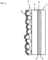
Fig. 3 is a diagram showing the layer structure of theplastic container 1 in a state where aliquid repellent agent 8 adheres to the surface of concave andconvex shapes 2c. -
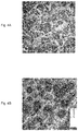
Fig. 4A and Fig. 4B are digital microscope images at a magnification of 100 times and 300 times, respectively. - Hereinafter, various embodiments of the present invention will be described. Various features described in the following embodiments can be combined with each other. In addition, an invention can be established independently for each of the features.
-
Fig. 1 is a schematic diagram of aplastic container 1 of an embodiment of the present invention. As shown inFig. 1 , thecontainer 1 is a container for storing contents. Examples of the contents include viscous substances, such as mayonnaise and ketchup. Thecontainer 1 is configured such that the contents are released from aspout 12 provided with athread 11 by squeezing abody portion 14, and thespout 12 is usually sealed with acap 13. Thecontainer 1 is a blow molded body formed by blow molding. The details of blow molding will be described later. - The
container 1 may have a single-layer structure or a multi-layer structure and preferably has a multi-layer structure.Fig. 2 shows an example of a layer structure of thecontainer 1, and the layer structure includes, in order from an inner surface side of thecontainer 1, aninnermost layer 2, anintermediate layer 3, anadhesive resin layer 4, abarrier layer 5, anadhesive resin layer 6, and anoutermost layer 7. In the layer structure of thecontainer 1, at least one of these layers may be omitted, and another layer may be included. Each layer will be described below. - The
outermost layer 7 is formed of a resin composition containing a thermoplastic resin, such as polyolefin, and the resin composition preferably contains a lubricant. This prevents the occurrence of problems due to poor slippage on the surface of thecontainer 1. - The
barrier layer 5 is formed of a resin with high gas barrier property. Examples of such a resin include ethylene vinyl alcohol copolymer (EVOH: including ethylene-vinyl acetate copolymer saponified product and the like), aromatic polyamide and the like. By providing thebarrier layer 5, oxidative degradation of the contents due to oxygen permeation can be effectively suppressed. - The
intermediate layer 3 is formed of a resin composition containing a thermoplastic resin, such as polyolefin. Theintermediate layer 3 may be omitted. Theintermediate layer 3 may be a repro layer made of a material recycled from burrs generated during blow molding of thecontainer 1. - The
adhesive resin layers adhesive resin layers barrier layer 5 and theoutermost layer 7 or theintermediate layer 3 can be improved. Instead of providing theadhesive resin layers barrier layer 5. - The
innermost layer 2 is a layer in contact with the contents and is formed of a resin composition containing abase resin 2a andfiller particles 2b. Concave andconvex shapes 2c (uneven shape) due to the presence of thefiller particles 2b are provided on an inner surface of the innermost layer 2 (that is, an inner surface of the container 1). Since the concave andconvex shapes 2c are provided on the inner surface of theinnermost layer 2, the friction between the inner surface of theinnermost layer 2 and the contents is reduced, and the slipping property is improved. - A ten-point average roughness Rz of the concave and
convex shapes 2c is preferably 7 to 500 µm, more preferably 10 to 300 µm, most preferably 10 to 100 µm. By setting the ten-point average roughness Rz within this range, the slipping property can be particularly improved. The ten-point average roughness Rz is defined in accordance with JIS B0601(-1982). - The
base resin 2a is preferably a thermoplastic resin, such as polyolefin. Examples of such polyolefin include polyethylene and polypropylene. - The
filler particles 2b are particles capable of providing the concave andconvex shapes 2c, and the filler particles containing at least one type of organic components and inorganic components can be adopted. - As the inorganic components, for example, 1) metals, such as aluminum, copper, iron, titanium, silver, and calcium, or alloys or intermetallic compounds containing these metals, 2) oxides, such as silicon oxide, aluminum oxide, zirconium oxide, titanium oxide, and iron oxide, 3) inorganic or organic acid salts, such as calcium phosphate and calcium stearate, 4) glass, and 5) ceramics, such as aluminum nitride, boron nitride, silicon carbide, and silicon nitride can be suitably used.
- As the organic components, for example, organic polymer components (or resin components), such as acrylic resin, urethane resin, melamine resin, amino resin, epoxy resin, polyethylene resin, polystyrene resin, polypropylene resin, polyester resin, cellulose resin, vinyl chloride resin, polyvinyl alcohol, ethylene-vinyl acetate copolymer, ethylene-vinyl alcohol copolymer, ethylene-ethyl acrylate copolymer, polyacrylonitrile, and polyamide can be suitably used.
- The
filler particle 2b is preferably acrylic resin. This is because the acrylic resin has high transparency, and thus the addition of thefiller particles 2b is unlikely to cause a decrease in transparency. - When Ta represents the melting point of the
base resin 2a, and Tb represents the melting point of thefiller particle 2b, Tb-Ta is preferably 10 °C or higher, more preferably 30 °C or higher, and even more preferably 50 °C or higher. This is because, if thefiller particles 2b are melted when thebase resin 2a is heated to melt in manufacturing thecontainer 1 by blow molding, it becomes difficult to form the concave andconvex shapes 2c. - The average particle diameter of the
filler particles 2b is preferably 10 to 100 µm, more preferably 20 to 80 µm, and even more preferably 30 to 50 µm. This average particle diameter may be specifically, for example, 10, 20, 30, 40, 50, 60, 70, 80, 90, 100 µm and may be within a range between any two of the values exemplified herein. If the average particle diameter is too small, it is difficult to form the concave andconvex shapes 2c, and if the average particle diameter is too large, thefiller particles 2b are likely to detach and fall off from theinnermost layer 2. The average particle diameter of thefiller particles 2b can be measured by a laser diffraction particle size analyzer. If it is difficult to measure it by the laser diffraction particle size analyzer, the particles can be observed by a microscope (or a photograph of the particles can be taken). If the particle has a spherical shape, its diameter can be used, and if the particle has a non-spherical shape, the average value of the largest diameter and the smallest diameter can be regarded as its diameter. Then, the average value of the diameters of 10 particles selected arbitrarily by microscopic observation can be used as the average particle diameter. - The shape of the
filler particles 2b is not particularly limited, and the particles may have, for example, a spherical shape, spheroid shape, irregular and indefinite shape, teardrop shape, flat shape, hollow shape, porous shape, or the like. - When T represents the average thickness of the
innermost layer 2 at the center of thecontainer 1 in the vertical direction, and D represents the average particle diameter of thefiller particles 2b, T/D is preferably 0.50 to 2.00, and more preferably 0.80 to 1.40. The average thickness of theinnermost layer 2 can be calculated by arithmetically averaging the thicknesses measured at four measuring points evenly spaced in the circumferential direction on the container wall surface cut out from the center of thecontainer 1 in the vertical direction. If T/D is too small, thefiller particles 2b are likely to detach and fall off from theinnermost layer 2, and if T/D is too large, the concave and convex shapes on the surface of theinnermost layer 2 tend to be insufficient. T/D may be specifically, for example, 0.50, 0.70, 0.80, 0.85, 0.90, 0.95, 1.00, 1.05, 1.10, 1.15, 1.20, 1.25, 1.30, 1.35, 1.40, 1.50, 2.00 and may be within a range between any two of the values exemplified herein. - Although the
filler particles 2b may be embedded in thebase resin 2a, it is preferable that at least a part of the particles is exposed from the inner surface of theinnermost layer 2. In such a case, the concave andconvex shapes 2c can be easily formed. Further, when thefiller particles 2b have slipping property superior to that of thebase resin 2a, the slipping property can be further improved by exposing thefiller particles 2b from the inner surface of theinnermost layer 2. - The content of the
filler particles 2b in the resin composition is preferably 15 to 50% by mass and more preferably 20 to 40% by mass. The content may be specifically, for example, 15, 20, 25, 30, 35, 40, 45, 50% by mass and may be within a range between any two of the values exemplified herein. If the content of thefiller particles 2b is too small, the concave andconvex shapes 2c tend to be insufficient, and if the content of thefiller particles 2b is too large, thefiller particles 2b are likely to detach and fall off from theinnermost layer 2. - A lubricant may be added to the resin composition forming the
innermost layer 2 to further improve the slipping property. - As shown in
Fig. 3 , it is preferable that a liquidrepellent agent 8 adheres to the surface of the concave andconvex shapes 2c. The slipping property can be further improved by adhering the liquidrepellent agent 8 to the surface of the concave andconvex shapes 2c. The liquidrepellent agent 8 includes at least one of hydrophobic particles and hydrophobic and oleophobic particles. This allows the liquidrepellent agent 8 to have at least one (preferably both) of water repellency and oil repellency and to inhibit adhesion of the contents even when the contents come into contact with it. - The average primary particle diameter of the hydrophobic particles is usually 3 to 100 nm, preferably 5 to 50 nm, and more preferably 7 to 30 nm. By setting the average primary particle diameter in the above range, the hydrophobic particles agglomerate moderately, and gas, such as air, can be retained in voids inside the agglomerate, so that the excellent slipping property can be realized. That is, since this agglomerated state is maintained even after adhering to the surface of the concave and
convex shapes 2c, the excellent slipping property can be realized. - In the present invention, the average primary particle diameter can be measured by a scanning electron microscope (FE-SEM), and another electron microscope, such as a transmission electron microscope may be used in combination for measurement if the resolution of the scanning electron microscope is low. Specifically, if the particles have a spherical shape, their diameter can be used, and if the particles have a non-spherical shape, the average value of the largest diameter and the smallest diameter can be regarded as the diameter. Then, the average value of the diameters of 20 particles selected arbitrarily by observation using the scanning electron microscope and the like can be used as the average primary particle diameter.
- The hydrophobic particles are not particularly limited as long as they have hydrophobic property, and those that have been hydrophobized by surface treatment may be used. For example, it is also possible to use fine particles in which hydrophilic oxide fine particles are surface-treated with a silane coupling agent or the like to make the surface state hydrophobic. The type of oxide is also not limited as long as it has hydrophobic property. For example, at least one of silica (silicon dioxide), alumina, titania and the like can be used. Among these, hydrophobic silica fine particles can be suitably used as the hydrophobic oxide particles. In particular, hydrophobic silica fine particles having a trimethylsilyl group on their surface are preferable in that more excellent non-adhesiveness can be obtained. Examples of commercially available products corresponding to this include "AEROSIL R812" and "AEROSIL R812S" (both manufactured by Evonik Degussa).
- As the oleophobic particles, for example, composite particles in which the surface of oxide fine particles is coated with a fluorine-based resin or the like can be used. As the oxide fine particles, for example, at least one type of oxide fine particles selected from particles (powder) of silicon oxide, titanium oxide, aluminum oxide, and zinc oxide can be used. In particular, silicon oxide particles are preferable. Commercially available products can also be used for these oxide fine particles.
- These commercially available oxide fine particles can be subjected to surface coating treatment to be suitably used as oleophobic particles. For example, regarding silicon oxide, using particles with the product name "AEROSIL 200" ("AEROSIL" is a registered trademark; the same applies hereinafter), "AEROSIL 130", "AEROSIL 300", "AEROSIL 50", "AEROSIL 200FAD", "AEROSIL 380" (all manufactured by NIPPON AEROSIL CO., LTD.) as the core, the surface of the core can be coated with a polyfluoroalkyl methacrylate resin, and the obtained oil repellent particles can be used. Regarding titanium oxide, for example, using particles with the product name "AEROXIDE TiO2 T805" (manufactured by Evonik Degussa) as the core, the surface of the core can be coated with a polyfluoroalkyl methacrylate resin, and the obtained oil repellent particles can be used. Regarding aluminum oxide, for example, using particles with the product name " AEROXIDE Alu C 805" (manufactured by Evonik Degussa) as the core, the surface of the core can be coated with a polyfluoroalkyl methacrylate resin, and the obtained oil repellent particles can be used.
- Since these oleophobic particles have a polyfluoroalkyl methacrylate resin on their surface, they can form a strong coating layer with relatively high adhesiveness on the surface of the particles due to their excellent affinity with the inorganic oxide particles and can also develop high non-adhesiveness to the contents.
- For the liquid
repellent agent 8, for example, a) a layer containing hydrophobic particles and oleophobic particles or b) a layer including a hydrophobic region containing hydrophobic particles and an oleophobic region containing oleophobic particles may be employed. By employing such a layer, the adhesion of contents can be suitably suppressed or prevented even when the contents is high in fat as well as moisture. - The content of the hydrophobic particles and the hydrophobic and oleophobic particles in the liquid
repellent agent 8 is not particularly limited and can be set as appropriate, usually within the range of 10 to 100% by weight. The closer the content of the hydrophobic particles and the hydrophobic and oleophobic particles is to 100% by weight, the higher the water repellency and/or oil repellency can be obtained. Therefore, the content of the hydrophobic particles and the hydrophobic and oleophobic particles in the liquidrepellent agent 8 can be set, for example, 98 to 100% by weight. - The amount of hydrophobic particles and hydrophobic and oleophobic particles adhered to the container body (weight after drying) is not particularly limited and is usually and preferably 0.01 to 10 g/m2, more preferably 0.2 to 1.5 g/m2, and most preferably 0.2 to 1 g/m2.
- Although the method for forming the liquid
repellent agent 8 is not particularly limited, it can be formed by a method including a process of applying and drying coating liquid containing at least one type of hydrophobic particles and oleophobic particles. - For example, dispersion liquid obtained by dispersing at least one type of hydrophobic particles and oleophobic particles in a solvent can be suitably used.
- Examples of the above solvent include organic solvents, for example, aromatic hydrocarbons, such as toluene and xylene, alicyclic hydrocarbon solvents, such as methylcyclohexane and cyclohexane, ester solvents, such as ethyl acetate and butyl acetate, ketone solvents, such as methyl ethyl ketone and acetone, alcohol solvents, such as isopropyl alcohol and denatured ethanol. These can be used alone or in combination of two or more.
- The solid content of the liquid
repellent agent 8 can be set as appropriate, usually within the range of 10 to 90% by weight, and particularly within the range of 20 to 80% by weight. - The coating liquid may contain other components as long as they do not interfere with the effects of the present invention. For example, resin binders, dispersants, or curing agents may be contained. In particular, in the present invention, the content of the resin component in the liquid
repellent agent 8 is preferably 5% by weight or less, more preferably 1% by weight or less, and more preferably substantially 0% by weight. By setting the content of the resin component to such amount, a higher effect of preventing adhesion can be realized. - The surface of the concave and
convex shapes 2c may be coated with the liquidrepellent agent 8 according to a known method, and for example, the spray method, the immersion method, or the stirring granulation method can be applied. In the present invention, coating by the spray method is particularly preferable in terms of excellent coating uniformity. - A drying process is performed after application. The drying process may be either natural drying or heat drying. In the case of heat drying, the temperature can be set, for example, 50 to 160 °C. In the coating of the present application, the above application and drying processes may be repeated twice or more to obtain a predetermined thickness.
- The
container 1 can be formed by blow molding of parison. The blow molding may be direct blow molding or injection blow molding. In direct blow molding, a tubular parison in a molten state extruded from an extruder is sandwiched between a pair of split molds, and air is blown into the parison to manufacture thecontainer 1. In injection blow molding, a bottomed parison in a shape of a test tube, known as a preform, is formed by injection molding, and blow molding is performed using this parison. - In any type of blow molding, the layer structure of the parison is the same as the layer structure of the
container 1. A multi-layered parison can be formed by coextrusion molding or multi-layer injection molding. An innermost layer of the parison is formed of the resin composition forming theinnermost layer 2 of the container 1 (that is, the resin composition containing thebase resin 2a and thefiller particles 2b). Although the innermost layer of the parison does not need to have concave and convex shapes on its surface, the shape of thefiller particles 2b appears, and the concave andconvex shapes 2c due to the presence of thefiller particles 2b are formed on an inner surface of theinnermost layer 2 because the parison is expanded, and its wall thickness decreases during blow molding. - By forming the
container 1 by blow molding and then directly spraying the liquidrepellent agent 8 or spraying the liquidrepellent agent 8 in a state dispersed or dissolved in a medium (dispersion medium or solvent), the liquidrepellent agent 8 can adhere to the surface of the concave andconvex shapes 2c. When the medium is used, a drying process may be performed as appropriate. - The
container 1 having a shape shown inFig. 1 was manufactured by direct blow molding of a parison. The innermost layer of the parison was formed of a resin composition containing thebase resin 2a and thefiller particles 2b. Thebase resin 2a is polyethylene (melting point: 112 °C), and thefiller particles 2b are acrylic resin (melting point: 230 °C) having an average particle diameter of 30 µm. The content of the filler particles in the resin composition was 20% by mass. - The thickness of the innermost layer of the parison was adjusted so that the thickness of the
innermost layer 2 at the center of thecontainer 1 in the vertical direction was 20 µm. - The
container 1 was manufactured in the same manner as in Manufacturing Example 1, except that the content of thefiller particles 2b, the average particle diameter D of thefiller particles 2b, and the thickness T of theinnermost layer 2 of thecontainer 1 were changed as shown in Table 1.[Table 1] Table 1 Manufacturing Example 1 2 3 4 5 6 7 8 9 10 Content of filler particles (% by mass) 20 20 20 20 20 20 20 15 50 40 Average particle diameter D of filler particles (µm) 30 30 30 30 50 50 50 30 30 30 Thickness T of innermost layer of container (µm) 20 30 40 50 40 50 60 30 30 30 T/D 0.67 1.00 1.33 1.67 0.80 1.00 1.20 1.00 1.00 1.00 Test on particle detachment B A A A A A A A B A Test on concave and convex shapes A A A B A A A B A A - A test piece (approximately 10 mm × 50 mm) was cut out from the
container 1 and is polished with synthetic paper (product name "Kimwipe" manufactured by Nippon Paper Crecia), and the detachment of fine particles was visually observed and evaluated according to the following criteria. - A: The detachment of the particles were not observed even after polishing 10 times or more.
- B: The detachment of the particles were observed after 3 to 9 times of polishing.
- C: The detachment of the particles were observed after polishing twice or less.
- The surface roughness Sa of the concave and convex shapes formed on the inner surface of the
container 1 was measured using a digital microscope (image dimension measuring device) and was evaluated according to the following criteria. - A: 2.5 µm or more
- B: 2 µm or more and less than 2.5 µm
- C: Less than 2 µm
- The inner surface of the
container 1 of Manufacturing Example 5 was photographed at a magnification of 100 times and 300 times using a digital microscope (image dimension measuring device). The particle diameter of 10filler particles 2b in the photograph taken at a magnification of 300 times was measured, and the arithmetic average of the measured values was 48.7 µm. - 1: plastic container, 2: innermost layer, 2a: base resin, 2b: filler particle, 2c: concave and convex shapes, 3: intermediate layer, 4: adhesive resin layer, 5: barrier layer, 6: adhesive resin layer, 7: outermost layer, 8: liquid repellent agent, 11: thread, 12: spout, 13: cap, 14: body portion
Claims (8)
- A plastic container for storing contents,wherein the plastic container is a blow molded body,an innermost layer in contact with the contents is formed of a resin composition containing a base resin and filler particles, andan inner surface of the innermost layer is provided with concave and convex shapes due to presence of the filler particles.
- The plastic container of Claim 1,
wherein T/D is 0.80 to 1.40 where T represents an average thickness of the innermost layer at a center of the plastic container in a vertical direction, and D represents an average particle diameter of the filler particles. - The plastic container of Claim 1 or Claim 2,
wherein at least a part of the filler particles is exposed from the inner surface of the innermost layer. - The plastic container of any one of Claim 1 to Claim 3,
wherein the resin composition has a content of the filler particles of 15 to 50% by mass. - The plastic container of any one of Claim 1 to Claim 4,
wherein the filler particles are formed of an acrylic resin. - The plastic container of any one of Claim 1 to Claim 5,
wherein the base resin is polyolefin. - The plastic container of any one of Claim 1 to Claim 6,
wherein a liquid repellent agent adheres to a surface of the concave and convex shapes. - A manufacturing method of the plastic container of any one of Claim 1 to Claim 7, comprising:a molding step of blow molding a parison,wherein an innermost layer of the parison is formed of the resin composition, andthe parison is expanded so that the concave and convex shapes are formed on an inner surface of the innermost layer by the filler particles.
Applications Claiming Priority (2)
| Application Number | Priority Date | Filing Date | Title |
|---|---|---|---|
| JP2019010513A JP7292629B2 (en) | 2019-01-24 | 2019-01-24 | Plastic container and its manufacturing method |
| PCT/JP2020/002285 WO2020153421A1 (en) | 2019-01-24 | 2020-01-23 | Plastic container and method for producing same |
Publications (3)
| Publication Number | Publication Date |
|---|---|
| EP3915761A1 true EP3915761A1 (en) | 2021-12-01 |
| EP3915761A4 EP3915761A4 (en) | 2022-02-09 |
| EP3915761B1 EP3915761B1 (en) | 2024-04-24 |
Family
ID=71736174
Family Applications (1)
| Application Number | Title | Priority Date | Filing Date |
|---|---|---|---|
| EP20744722.8A Active EP3915761B1 (en) | 2019-01-24 | 2020-01-23 | Plastic container and method for producing same |
Country Status (5)
| Country | Link |
|---|---|
| US (1) | US11851234B2 (en) |
| EP (1) | EP3915761B1 (en) |
| JP (2) | JP7292629B2 (en) |
| CN (1) | CN113302034B (en) |
| WO (1) | WO2020153421A1 (en) |
Families Citing this family (2)
| Publication number | Priority date | Publication date | Assignee | Title |
|---|---|---|---|---|
| JP2024079363A (en) * | 2022-11-30 | 2024-06-11 | 株式会社吉野工業所 | Manufacturing method of synthetic resin container |
| EP4527753A1 (en) * | 2023-09-21 | 2025-03-26 | Marcin Golec | Bottle with an internal coating layer |
Family Cites Families (15)
| Publication number | Priority date | Publication date | Assignee | Title |
|---|---|---|---|---|
| JP2011063272A (en) * | 2009-09-15 | 2011-03-31 | Toyo Seikan Kaisha Ltd | Multi-layered plastic container having superior appearance characteristics |
| JP5961935B2 (en) | 2011-06-29 | 2016-08-03 | キョーラク株式会社 | Plastic bottle |
| JP2013105411A (en) | 2011-11-16 | 2013-05-30 | Konica Minolta Business Technologies Inc | Sample print control program |
| KR101821324B1 (en) | 2012-07-13 | 2018-03-08 | 도요세이칸 그룹 홀딩스 가부시키가이샤 | Packaging container with excellent content slipperiness |
| KR20150109441A (en) * | 2013-02-08 | 2015-10-01 | 도요세이칸 그룹 홀딩스 가부시키가이샤 | Container having superior slide properties for fluid content |
| JP5713154B1 (en) * | 2013-04-24 | 2015-05-07 | 東洋製罐株式会社 | Method for producing blow-molded container excellent in slipperiness for fluid contents |
| JP5673870B1 (en) * | 2013-07-26 | 2015-02-18 | 東洋製罐グループホールディングス株式会社 | Resin structure having a liquid layer on the surface |
| EP3053840B1 (en) * | 2013-10-02 | 2018-12-12 | Kuraray Co., Ltd. | Blow-molded container, fuel container, blow-molded bottle container, and method for producing blow-molded container |
| JP6511735B2 (en) | 2014-06-03 | 2019-05-15 | 東洋製罐グループホールディングス株式会社 | Direct blow container |
| JP6734661B2 (en) * | 2016-02-19 | 2020-08-05 | 東罐興業株式会社 | Laminated structure provided with wax layer having uneven surface and method for manufacturing the same |
| RU2675145C1 (en) * | 2015-03-27 | 2018-12-17 | Тойо Сейкан Груп Холдингз, Лтд. | Structured product with hydrophobic surface and method for manufacture thereof |
| JP6587823B2 (en) | 2015-04-24 | 2019-10-09 | 東洋製罐株式会社 | Container with solid particles distributed on the surface |
| JP6069426B2 (en) | 2015-07-09 | 2017-02-01 | 東洋製罐グループホールディングス株式会社 | Container whose inner surface is formed of an olefin resin layer |
| JP6651319B2 (en) * | 2015-09-30 | 2020-02-19 | 東洋製罐グループホールディングス株式会社 | Packaging container |
| JP6579185B2 (en) * | 2017-12-06 | 2019-09-25 | 東洋製罐グループホールディングス株式会社 | Resin molding having a surface excellent in water slidability |
-
2019
- 2019-01-24 JP JP2019010513A patent/JP7292629B2/en active Active
-
2020
- 2020-01-23 WO PCT/JP2020/002285 patent/WO2020153421A1/en not_active Ceased
- 2020-01-23 CN CN202080009883.6A patent/CN113302034B/en active Active
- 2020-01-23 US US17/421,218 patent/US11851234B2/en active Active
- 2020-01-23 EP EP20744722.8A patent/EP3915761B1/en active Active
-
2023
- 2023-03-02 JP JP2023031522A patent/JP2023067934A/en active Pending
Also Published As
| Publication number | Publication date |
|---|---|
| JP2020117284A (en) | 2020-08-06 |
| US20220063858A1 (en) | 2022-03-03 |
| EP3915761A4 (en) | 2022-02-09 |
| JP7292629B2 (en) | 2023-06-19 |
| EP3915761B1 (en) | 2024-04-24 |
| CN113302034B (en) | 2023-08-22 |
| US11851234B2 (en) | 2023-12-26 |
| WO2020153421A1 (en) | 2020-07-30 |
| JP2023067934A (en) | 2023-05-16 |
| CN113302034A (en) | 2021-08-24 |
Similar Documents
| Publication | Publication Date | Title |
|---|---|---|
| EP3915761B1 (en) | Plastic container and method for producing same | |
| CN102576502A (en) | Label for in-mold molding, in-mold molded article and method for molding same | |
| KR20160085802A (en) | Thermoplastic resin film, label-attached hollow molded container, adhesive film, label, and film for printing use | |
| CN102164990A (en) | Films having low density and low haze | |
| EP3898236B1 (en) | Printable film | |
| CN111819612B (en) | Laminate and adhesive label | |
| JP2016047598A (en) | In-mold label, resin molded product and method for producing the same | |
| CN103826850A (en) | Barrier structure and laminate thereof | |
| CN102264606B (en) | Labeled container and method of manufacture | |
| JP2019166806A (en) | Water-repellent oil-repellent laminate | |
| JP2643745B2 (en) | Frost-shaped plastic container and method for producing the same | |
| JP7638068B2 (en) | Laminate | |
| JP6524180B2 (en) | Packaging material | |
| JP2019171805A (en) | Laminate for forming water-repellent laminate film and water-repellent laminate film | |
| JP7417035B2 (en) | laminated peel container | |
| JP2019171807A (en) | Laminate for forming water-repellent laminate film, water-repellent laminate film, and method for producing the same | |
| JP2019051596A (en) | Oil-repellent laminate | |
| JP4775797B2 (en) | Fluoropolymer film for laminating steel sheets | |
| JP4889841B2 (en) | Laminated polyolefin film with excellent printability | |
| CN1222570C (en) | Polyolefin resin composition | |
| JP2014000968A (en) | Method of manufacturing resin molding having water repellent surface | |
| JP2009061708A (en) | Method for producing gas barrier laminate film and laminate film | |
| JP2019108424A (en) | Oriented polyester film | |
| WO2022244218A1 (en) | Layered product | |
| CN114981053A (en) | Coated bag-in-containers |
Legal Events
| Date | Code | Title | Description |
|---|---|---|---|
| STAA | Information on the status of an ep patent application or granted ep patent |
Free format text: STATUS: THE INTERNATIONAL PUBLICATION HAS BEEN MADE |
|
| PUAI | Public reference made under article 153(3) epc to a published international application that has entered the european phase |
Free format text: ORIGINAL CODE: 0009012 |
|
| STAA | Information on the status of an ep patent application or granted ep patent |
Free format text: STATUS: REQUEST FOR EXAMINATION WAS MADE |
|
| 17P | Request for examination filed |
Effective date: 20210809 |
|
| AK | Designated contracting states |
Kind code of ref document: A1 Designated state(s): AL AT BE BG CH CY CZ DE DK EE ES FI FR GB GR HR HU IE IS IT LI LT LU LV MC MK MT NL NO PL PT RO RS SE SI SK SM TR |
|
| A4 | Supplementary search report drawn up and despatched |
Effective date: 20220111 |
|
| RIC1 | Information provided on ipc code assigned before grant |
Ipc: B29K 105/00 20060101ALN20220104BHEP Ipc: B29K 505/00 20060101ALN20220104BHEP Ipc: B29K 23/00 20060101ALN20220104BHEP Ipc: B29C 49/00 20060101ALN20220104BHEP Ipc: B29L 23/00 20060101ALI20220104BHEP Ipc: B29L 31/00 20060101ALI20220104BHEP Ipc: B65D 35/14 20060101ALI20220104BHEP Ipc: B65D 1/40 20060101ALI20220104BHEP Ipc: B65D 1/02 20060101ALI20220104BHEP Ipc: B65D 23/04 20060101ALI20220104BHEP Ipc: B65D 23/02 20060101ALI20220104BHEP Ipc: B29C 49/22 20060101AFI20220104BHEP |
|
| DAV | Request for validation of the european patent (deleted) | ||
| DAX | Request for extension of the european patent (deleted) | ||
| GRAP | Despatch of communication of intention to grant a patent |
Free format text: ORIGINAL CODE: EPIDOSNIGR1 |
|
| STAA | Information on the status of an ep patent application or granted ep patent |
Free format text: STATUS: GRANT OF PATENT IS INTENDED |
|
| RIC1 | Information provided on ipc code assigned before grant |
Ipc: B29K 105/00 20060101ALN20231102BHEP Ipc: B29K 505/00 20060101ALN20231102BHEP Ipc: B29K 23/00 20060101ALN20231102BHEP Ipc: B29C 49/00 20060101ALN20231102BHEP Ipc: B29L 23/00 20060101ALI20231102BHEP Ipc: B29L 31/00 20060101ALI20231102BHEP Ipc: B65D 35/14 20060101ALI20231102BHEP Ipc: B65D 1/40 20060101ALI20231102BHEP Ipc: B65D 1/02 20060101ALI20231102BHEP Ipc: B65D 23/04 20060101ALI20231102BHEP Ipc: B65D 23/02 20060101ALI20231102BHEP Ipc: B29C 49/22 20060101AFI20231102BHEP |
|
| INTG | Intention to grant announced |
Effective date: 20231117 |
|
| GRAS | Grant fee paid |
Free format text: ORIGINAL CODE: EPIDOSNIGR3 |
|
| GRAA | (expected) grant |
Free format text: ORIGINAL CODE: 0009210 |
|
| STAA | Information on the status of an ep patent application or granted ep patent |
Free format text: STATUS: THE PATENT HAS BEEN GRANTED |
|
| AK | Designated contracting states |
Kind code of ref document: B1 Designated state(s): AL AT BE BG CH CY CZ DE DK EE ES FI FR GB GR HR HU IE IS IT LI LT LU LV MC MK MT NL NO PL PT RO RS SE SI SK SM TR |
|
| REG | Reference to a national code |
Ref country code: GB Ref legal event code: FG4D |
|
| REG | Reference to a national code |
Ref country code: CH Ref legal event code: EP |
|
| REG | Reference to a national code |
Ref country code: DE Ref legal event code: R096 Ref document number: 602020029624 Country of ref document: DE |
|
| REG | Reference to a national code |
Ref country code: IE Ref legal event code: FG4D |
|
| REG | Reference to a national code |
Ref country code: LT Ref legal event code: MG9D |
|
| REG | Reference to a national code |
Ref country code: NL Ref legal event code: MP Effective date: 20240424 |
|
| REG | Reference to a national code |
Ref country code: AT Ref legal event code: MK05 Ref document number: 1679141 Country of ref document: AT Kind code of ref document: T Effective date: 20240424 |
|
| PG25 | Lapsed in a contracting state [announced via postgrant information from national office to epo] |
Ref country code: NL Free format text: LAPSE BECAUSE OF FAILURE TO SUBMIT A TRANSLATION OF THE DESCRIPTION OR TO PAY THE FEE WITHIN THE PRESCRIBED TIME-LIMIT Effective date: 20240424 |
|
| PG25 | Lapsed in a contracting state [announced via postgrant information from national office to epo] |
Ref country code: NL Free format text: LAPSE BECAUSE OF FAILURE TO SUBMIT A TRANSLATION OF THE DESCRIPTION OR TO PAY THE FEE WITHIN THE PRESCRIBED TIME-LIMIT Effective date: 20240424 |
|
| PG25 | Lapsed in a contracting state [announced via postgrant information from national office to epo] |
Ref country code: IS Free format text: LAPSE BECAUSE OF FAILURE TO SUBMIT A TRANSLATION OF THE DESCRIPTION OR TO PAY THE FEE WITHIN THE PRESCRIBED TIME-LIMIT Effective date: 20240824 |
|
| PG25 | Lapsed in a contracting state [announced via postgrant information from national office to epo] |
Ref country code: BG Free format text: LAPSE BECAUSE OF FAILURE TO SUBMIT A TRANSLATION OF THE DESCRIPTION OR TO PAY THE FEE WITHIN THE PRESCRIBED TIME-LIMIT Effective date: 20240424 |
|
| PG25 | Lapsed in a contracting state [announced via postgrant information from national office to epo] |
Ref country code: FI Free format text: LAPSE BECAUSE OF FAILURE TO SUBMIT A TRANSLATION OF THE DESCRIPTION OR TO PAY THE FEE WITHIN THE PRESCRIBED TIME-LIMIT Effective date: 20240424 Ref country code: HR Free format text: LAPSE BECAUSE OF FAILURE TO SUBMIT A TRANSLATION OF THE DESCRIPTION OR TO PAY THE FEE WITHIN THE PRESCRIBED TIME-LIMIT Effective date: 20240424 |
|
| PG25 | Lapsed in a contracting state [announced via postgrant information from national office to epo] |
Ref country code: GR Free format text: LAPSE BECAUSE OF FAILURE TO SUBMIT A TRANSLATION OF THE DESCRIPTION OR TO PAY THE FEE WITHIN THE PRESCRIBED TIME-LIMIT Effective date: 20240725 |
|
| PG25 | Lapsed in a contracting state [announced via postgrant information from national office to epo] |
Ref country code: PT Free format text: LAPSE BECAUSE OF FAILURE TO SUBMIT A TRANSLATION OF THE DESCRIPTION OR TO PAY THE FEE WITHIN THE PRESCRIBED TIME-LIMIT Effective date: 20240826 |
|
| PG25 | Lapsed in a contracting state [announced via postgrant information from national office to epo] |
Ref country code: ES Free format text: LAPSE BECAUSE OF FAILURE TO SUBMIT A TRANSLATION OF THE DESCRIPTION OR TO PAY THE FEE WITHIN THE PRESCRIBED TIME-LIMIT Effective date: 20240424 |
|
| PG25 | Lapsed in a contracting state [announced via postgrant information from national office to epo] |
Ref country code: AT Free format text: LAPSE BECAUSE OF FAILURE TO SUBMIT A TRANSLATION OF THE DESCRIPTION OR TO PAY THE FEE WITHIN THE PRESCRIBED TIME-LIMIT Effective date: 20240424 |
|
| PG25 | Lapsed in a contracting state [announced via postgrant information from national office to epo] |
Ref country code: PL Free format text: LAPSE BECAUSE OF FAILURE TO SUBMIT A TRANSLATION OF THE DESCRIPTION OR TO PAY THE FEE WITHIN THE PRESCRIBED TIME-LIMIT Effective date: 20240424 |
|
| PG25 | Lapsed in a contracting state [announced via postgrant information from national office to epo] |
Ref country code: LV Free format text: LAPSE BECAUSE OF FAILURE TO SUBMIT A TRANSLATION OF THE DESCRIPTION OR TO PAY THE FEE WITHIN THE PRESCRIBED TIME-LIMIT Effective date: 20240424 |
|
| PG25 | Lapsed in a contracting state [announced via postgrant information from national office to epo] |
Ref country code: PT Free format text: LAPSE BECAUSE OF FAILURE TO SUBMIT A TRANSLATION OF THE DESCRIPTION OR TO PAY THE FEE WITHIN THE PRESCRIBED TIME-LIMIT Effective date: 20240826 Ref country code: PL Free format text: LAPSE BECAUSE OF FAILURE TO SUBMIT A TRANSLATION OF THE DESCRIPTION OR TO PAY THE FEE WITHIN THE PRESCRIBED TIME-LIMIT Effective date: 20240424 Ref country code: NO Free format text: LAPSE BECAUSE OF FAILURE TO SUBMIT A TRANSLATION OF THE DESCRIPTION OR TO PAY THE FEE WITHIN THE PRESCRIBED TIME-LIMIT Effective date: 20240724 Ref country code: LV Free format text: LAPSE BECAUSE OF FAILURE TO SUBMIT A TRANSLATION OF THE DESCRIPTION OR TO PAY THE FEE WITHIN THE PRESCRIBED TIME-LIMIT Effective date: 20240424 Ref country code: IS Free format text: LAPSE BECAUSE OF FAILURE TO SUBMIT A TRANSLATION OF THE DESCRIPTION OR TO PAY THE FEE WITHIN THE PRESCRIBED TIME-LIMIT Effective date: 20240824 Ref country code: HR Free format text: LAPSE BECAUSE OF FAILURE TO SUBMIT A TRANSLATION OF THE DESCRIPTION OR TO PAY THE FEE WITHIN THE PRESCRIBED TIME-LIMIT Effective date: 20240424 Ref country code: GR Free format text: LAPSE BECAUSE OF FAILURE TO SUBMIT A TRANSLATION OF THE DESCRIPTION OR TO PAY THE FEE WITHIN THE PRESCRIBED TIME-LIMIT Effective date: 20240725 Ref country code: FI Free format text: LAPSE BECAUSE OF FAILURE TO SUBMIT A TRANSLATION OF THE DESCRIPTION OR TO PAY THE FEE WITHIN THE PRESCRIBED TIME-LIMIT Effective date: 20240424 Ref country code: ES Free format text: LAPSE BECAUSE OF FAILURE TO SUBMIT A TRANSLATION OF THE DESCRIPTION OR TO PAY THE FEE WITHIN THE PRESCRIBED TIME-LIMIT Effective date: 20240424 Ref country code: BG Free format text: LAPSE BECAUSE OF FAILURE TO SUBMIT A TRANSLATION OF THE DESCRIPTION OR TO PAY THE FEE WITHIN THE PRESCRIBED TIME-LIMIT Effective date: 20240424 Ref country code: AT Free format text: LAPSE BECAUSE OF FAILURE TO SUBMIT A TRANSLATION OF THE DESCRIPTION OR TO PAY THE FEE WITHIN THE PRESCRIBED TIME-LIMIT Effective date: 20240424 Ref country code: RS Free format text: LAPSE BECAUSE OF FAILURE TO SUBMIT A TRANSLATION OF THE DESCRIPTION OR TO PAY THE FEE WITHIN THE PRESCRIBED TIME-LIMIT Effective date: 20240724 |
|
| PG25 | Lapsed in a contracting state [announced via postgrant information from national office to epo] |
Ref country code: DK Free format text: LAPSE BECAUSE OF FAILURE TO SUBMIT A TRANSLATION OF THE DESCRIPTION OR TO PAY THE FEE WITHIN THE PRESCRIBED TIME-LIMIT Effective date: 20240424 |
|
| PG25 | Lapsed in a contracting state [announced via postgrant information from national office to epo] |
Ref country code: EE Free format text: LAPSE BECAUSE OF FAILURE TO SUBMIT A TRANSLATION OF THE DESCRIPTION OR TO PAY THE FEE WITHIN THE PRESCRIBED TIME-LIMIT Effective date: 20240424 |
|
| PG25 | Lapsed in a contracting state [announced via postgrant information from national office to epo] |
Ref country code: CZ Free format text: LAPSE BECAUSE OF FAILURE TO SUBMIT A TRANSLATION OF THE DESCRIPTION OR TO PAY THE FEE WITHIN THE PRESCRIBED TIME-LIMIT Effective date: 20240424 |
|
| PG25 | Lapsed in a contracting state [announced via postgrant information from national office to epo] |
Ref country code: RO Free format text: LAPSE BECAUSE OF FAILURE TO SUBMIT A TRANSLATION OF THE DESCRIPTION OR TO PAY THE FEE WITHIN THE PRESCRIBED TIME-LIMIT Effective date: 20240424 Ref country code: SK Free format text: LAPSE BECAUSE OF FAILURE TO SUBMIT A TRANSLATION OF THE DESCRIPTION OR TO PAY THE FEE WITHIN THE PRESCRIBED TIME-LIMIT Effective date: 20240424 |
|
| REG | Reference to a national code |
Ref country code: DE Ref legal event code: R097 Ref document number: 602020029624 Country of ref document: DE |
|
| PG25 | Lapsed in a contracting state [announced via postgrant information from national office to epo] |
Ref country code: SM Free format text: LAPSE BECAUSE OF FAILURE TO SUBMIT A TRANSLATION OF THE DESCRIPTION OR TO PAY THE FEE WITHIN THE PRESCRIBED TIME-LIMIT Effective date: 20240424 |
|
| PG25 | Lapsed in a contracting state [announced via postgrant information from national office to epo] |
Ref country code: SM Free format text: LAPSE BECAUSE OF FAILURE TO SUBMIT A TRANSLATION OF THE DESCRIPTION OR TO PAY THE FEE WITHIN THE PRESCRIBED TIME-LIMIT Effective date: 20240424 Ref country code: SK Free format text: LAPSE BECAUSE OF FAILURE TO SUBMIT A TRANSLATION OF THE DESCRIPTION OR TO PAY THE FEE WITHIN THE PRESCRIBED TIME-LIMIT Effective date: 20240424 Ref country code: RO Free format text: LAPSE BECAUSE OF FAILURE TO SUBMIT A TRANSLATION OF THE DESCRIPTION OR TO PAY THE FEE WITHIN THE PRESCRIBED TIME-LIMIT Effective date: 20240424 Ref country code: EE Free format text: LAPSE BECAUSE OF FAILURE TO SUBMIT A TRANSLATION OF THE DESCRIPTION OR TO PAY THE FEE WITHIN THE PRESCRIBED TIME-LIMIT Effective date: 20240424 Ref country code: DK Free format text: LAPSE BECAUSE OF FAILURE TO SUBMIT A TRANSLATION OF THE DESCRIPTION OR TO PAY THE FEE WITHIN THE PRESCRIBED TIME-LIMIT Effective date: 20240424 Ref country code: CZ Free format text: LAPSE BECAUSE OF FAILURE TO SUBMIT A TRANSLATION OF THE DESCRIPTION OR TO PAY THE FEE WITHIN THE PRESCRIBED TIME-LIMIT Effective date: 20240424 |
|
| PLBE | No opposition filed within time limit |
Free format text: ORIGINAL CODE: 0009261 |
|
| STAA | Information on the status of an ep patent application or granted ep patent |
Free format text: STATUS: NO OPPOSITION FILED WITHIN TIME LIMIT |
|
| 26N | No opposition filed |
Effective date: 20250127 |
|
| PG25 | Lapsed in a contracting state [announced via postgrant information from national office to epo] |
Ref country code: SI Free format text: LAPSE BECAUSE OF FAILURE TO SUBMIT A TRANSLATION OF THE DESCRIPTION OR TO PAY THE FEE WITHIN THE PRESCRIBED TIME-LIMIT Effective date: 20240424 |
|
| REG | Reference to a national code |
Ref country code: CH Ref legal event code: PL |
|
| PG25 | Lapsed in a contracting state [announced via postgrant information from national office to epo] |
Ref country code: SE Free format text: LAPSE BECAUSE OF FAILURE TO SUBMIT A TRANSLATION OF THE DESCRIPTION OR TO PAY THE FEE WITHIN THE PRESCRIBED TIME-LIMIT Effective date: 20240424 |
|
| PG25 | Lapsed in a contracting state [announced via postgrant information from national office to epo] |
Ref country code: MC Free format text: LAPSE BECAUSE OF FAILURE TO SUBMIT A TRANSLATION OF THE DESCRIPTION OR TO PAY THE FEE WITHIN THE PRESCRIBED TIME-LIMIT Effective date: 20240424 Ref country code: LU Free format text: LAPSE BECAUSE OF NON-PAYMENT OF DUE FEES Effective date: 20250123 |
|
| PG25 | Lapsed in a contracting state [announced via postgrant information from national office to epo] |
Ref country code: BE Free format text: LAPSE BECAUSE OF NON-PAYMENT OF DUE FEES Effective date: 20250131 |
|
| PG25 | Lapsed in a contracting state [announced via postgrant information from national office to epo] |
Ref country code: CH Free format text: LAPSE BECAUSE OF NON-PAYMENT OF DUE FEES Effective date: 20250131 |
|
| REG | Reference to a national code |
Ref country code: BE Ref legal event code: MM Effective date: 20250131 |
|
| PG25 | Lapsed in a contracting state [announced via postgrant information from national office to epo] |
Ref country code: IE Free format text: LAPSE BECAUSE OF NON-PAYMENT OF DUE FEES Effective date: 20250123 |
|
| PG25 | Lapsed in a contracting state [announced via postgrant information from national office to epo] |
Ref country code: IT Free format text: LAPSE BECAUSE OF FAILURE TO SUBMIT A TRANSLATION OF THE DESCRIPTION OR TO PAY THE FEE WITHIN THE PRESCRIBED TIME-LIMIT Effective date: 20240424 |
|
| PGFP | Annual fee paid to national office [announced via postgrant information from national office to epo] |
Ref country code: GB Payment date: 20260123 Year of fee payment: 7 |
|
| PGFP | Annual fee paid to national office [announced via postgrant information from national office to epo] |
Ref country code: DE Payment date: 20260121 Year of fee payment: 7 |
|
| PGFP | Annual fee paid to national office [announced via postgrant information from national office to epo] |
Ref country code: FR Payment date: 20260123 Year of fee payment: 7 |