EP3915293B1 - Service cell selection - Google Patents
Service cell selection Download PDFInfo
- Publication number
- EP3915293B1 EP3915293B1 EP20705450.3A EP20705450A EP3915293B1 EP 3915293 B1 EP3915293 B1 EP 3915293B1 EP 20705450 A EP20705450 A EP 20705450A EP 3915293 B1 EP3915293 B1 EP 3915293B1
- Authority
- EP
- European Patent Office
- Prior art keywords
- cell
- listening
- user equipment
- cells
- service
- Prior art date
- Legal status (The legal status is an assumption and is not a legal conclusion. Google has not performed a legal analysis and makes no representation as to the accuracy of the status listed.)
- Active
Links
- 238000000034 method Methods 0.000 claims description 65
- 230000006854 communication Effects 0.000 claims description 25
- 238000004891 communication Methods 0.000 claims description 25
- 230000008569 process Effects 0.000 claims description 24
- 238000003064 k means clustering Methods 0.000 claims description 16
- 238000012545 processing Methods 0.000 claims description 15
- 230000003213 activating effect Effects 0.000 claims description 8
- 230000007717 exclusion Effects 0.000 claims description 3
- 230000009471 action Effects 0.000 description 3
- 230000004913 activation Effects 0.000 description 3
- 230000005540 biological transmission Effects 0.000 description 3
- 230000008901 benefit Effects 0.000 description 2
- 230000003993 interaction Effects 0.000 description 2
- 230000002452 interceptive effect Effects 0.000 description 2
- 238000012804 iterative process Methods 0.000 description 2
- 238000013507 mapping Methods 0.000 description 2
- 239000005437 stratosphere Substances 0.000 description 2
- 241000760358 Enodes Species 0.000 description 1
- 239000000654 additive Substances 0.000 description 1
- 238000013459 approach Methods 0.000 description 1
- 230000007175 bidirectional communication Effects 0.000 description 1
- 230000002457 bidirectional effect Effects 0.000 description 1
- 230000015572 biosynthetic process Effects 0.000 description 1
- 230000001413 cellular effect Effects 0.000 description 1
- 230000006835 compression Effects 0.000 description 1
- 238000007906 compression Methods 0.000 description 1
- 238000001514 detection method Methods 0.000 description 1
- 230000000694 effects Effects 0.000 description 1
- 238000005516 engineering process Methods 0.000 description 1
- 230000006870 function Effects 0.000 description 1
- 230000007774 longterm Effects 0.000 description 1
- 230000011664 signaling Effects 0.000 description 1
- 230000003595 spectral effect Effects 0.000 description 1
- 238000001228 spectrum Methods 0.000 description 1
- 239000000758 substrate Substances 0.000 description 1
- 238000012546 transfer Methods 0.000 description 1
Images


Classifications
-
- H—ELECTRICITY
- H04—ELECTRIC COMMUNICATION TECHNIQUE
- H04B—TRANSMISSION
- H04B7/00—Radio transmission systems, i.e. using radiation field
- H04B7/14—Relay systems
- H04B7/15—Active relay systems
- H04B7/185—Space-based or airborne stations; Stations for satellite systems
- H04B7/18502—Airborne stations
- H04B7/18504—Aircraft used as relay or high altitude atmospheric platform
-
- H—ELECTRICITY
- H04—ELECTRIC COMMUNICATION TECHNIQUE
- H04W—WIRELESS COMMUNICATION NETWORKS
- H04W84/00—Network topologies
- H04W84/02—Hierarchically pre-organised networks, e.g. paging networks, cellular networks, WLAN [Wireless Local Area Network] or WLL [Wireless Local Loop]
- H04W84/04—Large scale networks; Deep hierarchical networks
- H04W84/06—Airborne or Satellite Networks
-
- H—ELECTRICITY
- H04—ELECTRIC COMMUNICATION TECHNIQUE
- H04B—TRANSMISSION
- H04B7/00—Radio transmission systems, i.e. using radiation field
- H04B7/14—Relay systems
- H04B7/15—Active relay systems
- H04B7/185—Space-based or airborne stations; Stations for satellite systems
- H04B7/18502—Airborne stations
-
- H—ELECTRICITY
- H04—ELECTRIC COMMUNICATION TECHNIQUE
- H04W—WIRELESS COMMUNICATION NETWORKS
- H04W16/00—Network planning, e.g. coverage or traffic planning tools; Network deployment, e.g. resource partitioning or cells structures
- H04W16/24—Cell structures
- H04W16/26—Cell enhancers or enhancement, e.g. for tunnels, building shadow
-
- H—ELECTRICITY
- H04—ELECTRIC COMMUNICATION TECHNIQUE
- H04W—WIRELESS COMMUNICATION NETWORKS
- H04W24/00—Supervisory, monitoring or testing arrangements
- H04W24/02—Arrangements for optimising operational condition
-
- H—ELECTRICITY
- H04—ELECTRIC COMMUNICATION TECHNIQUE
- H04W—WIRELESS COMMUNICATION NETWORKS
- H04W48/00—Access restriction; Network selection; Access point selection
- H04W48/16—Discovering, processing access restriction or access information
Definitions
- the present invention relates to a method and apparatus for providing service cells for wireless communication between user equipment and a core network.
- the present invention relates to the initial provision of multiple listening cells, via an aerial vehicle such as a high altitude platform (HAP), followed by the provision of one or more service cells at certain locations after determining which of the initial listening cells satisfy a predetermined condition.
- HAP high altitude platform
- HAPs High altitude platforms
- LOS Line-of-Sight
- geostationary satellites are located approximately 1800 x further from the earth's surface than HAPs.
- Wireless networks are required to deliver high aggregate data rates within a limited bandwidth through efficient spectral use.
- a way this can be achieved is to use directional antennas on each HAP.
- user equipment such as mobile phones, tablets or laptops or other such user devices can communicate wirelessly with a number of HAPs equipped with directional antennas such as horn or multi-element phased array antennas. These antennas can be utilised to form beams towards the ground thus illuminating "cells" that can be perceived by the user equipment as conventional terrestrial cells.
- An advantage of this approach relative to non-aerial vehicle based communication networks is that the locations and density of cells created by the HAPs are dynamically controllable and do not involve changes to the infrastructure on the ground.
- US patent number 9,913,278 describes wireless service being provided to a service area using limited resources dynamically reallocated to maximize capacity in high demand regions.
- HAP high altitude platform
- HAP high altitude platform
- a method of providing service cells for wireless communication between user equipment and a core network comprising the steps of:
- the step of providing at least one service cell comprises, for each qualifying listening cell, activating a service cell having an associated service cell coverage area centred proximate to a respective centre of a listening cell cell coverage area of the qualifying listening cell.
- the step of determining which listening cells are qualifying listening cells comprises determining how many user equipment are associated with each listening cell and for each listening cell, determining if a number of associated user equipment satisfies at least one predetermined condition.
- the predetermined condition is that the number of user equipment is equal to or greater than a predetermined minimum number or that the number is high enough to make the cell a cell with a qualifyingly high number of user equipment or that the number of user equipment is equal to or greater than a predetermined proportion of total user equipment located in the service area.
- the method further provides the wireless signal by broadcasting respective beacon signals from the aerial vehicle for each listening cell.
- the method further comprises determining the at least one parameter by determining a signal strength of each received wireless signal at each user equipment and for each user equipment, providing an associated request signal to the listening cell that is associated with a wireless signal that has a greatest signal strength of all wireless signals received at the user equipment.
- the method further comprises subsequent to determining which listening cells are qualifying cells, via a clustering algorithm, determining an improved location as a centre point for a service cell associated with that listening cell, said improved location being a location geographically offset from a previously suggested centre for the listening cell and subsequently providing a service cell having an associated service cell cell coverage area centred on the improved location.
- the method further comprises determining the improved location by, via a clustering unit that performs a clustering algorithm, iteratively recalculating a proposed centre point responsive to a determined carrier to noise ratio for user equipment in a cluster edge region of a cluster of user equipment in each service cell.
- the clustering algorithm comprises a K means clustering algorithm or RF-K means clustering algorithm or RF clustering algorithm.
- the service area has an average width of 30km or more.
- the method further comprises simultaneously or one-by-one, determining which listening cells are qualifying listening cells.
- the method further comprises providing the listening cells via an aerial vehicle that is a high altitude platform (HAP).
- HAP high altitude platform
- the HAP is at an altitude of 15 to 30km above sea level.
- the method further comprises providing the listening cells by dynamically directing a respective beam from the aerial vehicle at a plurality of respective target locations within the service area.
- the method further comprises determining a placement and/or a shape of each of the service cells responsive to at least one iterative clustering process.
- the method further comprises prioritising the provision of cell islands of cell coverage, provided by the aerial vehicle, responsive to the identification of user hot spots in the service area.
- the method further comprises prioritising a lack of provision of cell coverage, thereby providing respective islands of exclusion of cell coverage, provided by the aerial vehicle, responsive to the identification of geographical borders and/or at least one service area associated with a further communication network.
- the step of determining which cells are qualifying listening cells comprises determining if a listening cell is associated with one or more high priority user equipment and for each listening cell that is associated with at least one high priority user equipment, determining if a number of associated high priority user equipment satisfies at least one predetermined condition.
- an aerial vehicle for providing service cells for wireless communication between user equipment (UE) and a core network, comprising at least one directional antenna and a controller that includes at least one processing element for providing a plurality of listening cells across a service area associated with the aerial vehicle, each listening cell covering at least a portion of the service area, for associating user equipment located in the service area with at least one listening cell, wherein associating the user equipment comprises determining at least one parameter associated with a wireless signal transmitted from the aerial vehicle to the user equipment, and responsive to the parameter, providing an association request signal from the user equipment to the aerial vehicle, for determining which listening cells are qualifying listening cells that are listening cells that satisfy at least one predetermined condition and subsequently providing at least one service cell in the service area for each qualifying listening cell, wherein providing the at least one service cell comprises activating the service cell for each qualifying listening cell.
- UE user equipment
- a core network comprising at least one directional antenna and a controller that includes at least one processing element for providing a plurality of listening cells across a service area associated with the
- the controller includes at least one processing element for each qualifying listening cell, activating a service cell having an associated service cell coverage area centred proximate to a respective centre of a listening cell coverage area of the qualifying listening cells.
- Certain embodiments of the present invention provide a method and apparatus for providing service cells for wireless communication between user equipment and a core network. By first providing a plurality of listening cells across an entire service area associated with an aerial vehicle and then determining which of those listening cells are qualifying listening cells in the sense that they satisfy a predetermined condition, one or more fully functioning service cells can subsequently be provided in the service area where needed.
- Certain embodiments of the present invention provide a method and apparatus whereby account can be taken of numbers of users in particular geographical areas (or a priority of users associated with priority user equipment in particular areas or other particular parameters) so that once identified across a service area service cells can be provided to provide wireless communication between those user equipment and a core network.
- Certain embodiments of the present invention provide for an antenna beam pointing scheme using a process which determines clusters of user equipment in geographical areas and subsequently creates service cells focussed on high density areas.
- Certain embodiments of the present invention help make use of limited resources on an aerial vehicle, such as a HAP, by prioritising islands of coverage delivered from a HAP by focussing on user hotspots.
- islands of exclusion can be prioritised to assist with coexistence with terrestrial and other systems.
- methodologies can be provided to help prioritise throughput and throughput density.
- Certain embodiments of the present invention provide for an antenna beam pointing process which can be used on a high altitude platform (HAP) and/or other forms of lower altitude airborne platforms.
- HAP high altitude platform
- Certain embodiments of the present invention provide for one or more HAPS which can achieve line or sight (LoS) connectivity with terrestrial based user equipment (UE) and which can allow for rapid service deployment.
- a single HAP equipped with an array of antennas can deploy many beams, each of which can form a cell, and unlike in a terrestrial situation, the cells can be dynamically directed anywhere inside a geographical service area according to short or long-term fluctuations in demand.
- Certain embodiments of the present invention provide for high speed broadband services from high altitude platforms (HAPs). Certain embodiments of the present invention provide for high speed broadband services from low altitude platforms (LAPs).
- a HAP may be an aircraft or lighter than air structure 10 to 35 km above sea level.
- a LAP may be an aircraft or lighter than air structure 0.1 km to 10 km above sea level.
- a High Altitude Long Endurance (HALE) aircraft or free flying or tethered aerostat can be an example of a HAP.
- a HAP is an example of an aerial vehicle.
- a quadcopter or a drone are examples of LAPs. Other such aerial vehicles such as tethered vehicles or manned aircraft or the like can be utilised according to other embodiments of the present invention.
- each aerial vehicle is deployed at least 5 km above sea level.
- each LAP is deployed at least 1 km above sea level.
- Aptly each aerial vehicle can be deployed in the stratosphere at an altitude above sea level of around 17 to 22 km.
- HAPs and LAPs cover significantly wider areas with Line-of-Sight (LoS) links compared to conventional terrestrial systems and do not suffer from capacity and propagation delay limitations associated with satellites.
- LoS Line-of-Sight
- FIG 1 illustrates how at least one aerial vehicle 100 (one HAP shown in Figure 1 ) can provide wireless services to user equipment.
- a user equipment can be a mobile phone, tablet or laptop or PDA or a device that acts as a relay or the like.
- Each user equipment described hereinbelow, by way of example only, is a smartphone.
- Each aerial vehicle described hereinbelow, by way of example only, is a HAP.
- Each HAP shown is equipped with one or more directional antenna 110. Aptly each directional antenna is a multi-element phased array antenna. Such antennas and their general control is described in GB2536015 .
- each aerial vehicle 100 alone can form one or more beams which are directed to the ground thus illuminating 'cells'.
- the beams provided by a single HAP can be used to provide a single channel wireless communication link between the respective HAP and a user equipment in each cell 130.
- the wireless communication link is two way or bidirectional in the sense that uplink and downlink transfer of data can be supported.
- the cells 130 can be perceived by the user equipment as conventional terrestrial wireless telecommunication cells.
- the locations and density of cells created by the HAPs are dynamically controllable. That is to say over time the locations where cells are directed and/or numbers of cells and/or size and/or shape of cells can be modified. Optionally this is carried out in real time.
- Each aerial vehicle supports at least one directional antenna.
- each vehicle supports a phased array antenna 110.
- a transmission antenna and a reception antenna could be utilised.
- horns could be used or other such transmission/reception members.
- Each phased array antenna can comprise an array of small antenna elements.
- Each single channel wireless communication link is formed over the channel between a single user equipment and a single HAP.
- the single channel communication link is provided by forming a beam, from a directional antenna of a respective aerial vehicle, towards the ground that illuminates a first cell coverage area.
- the first cell coverage area has a relatively wide footprint and may thus be referred to as a wide cell. Aptly the footprint has a width of greater than 500 m.
- the single channel communication link enables synchronisation and/or association and/or exchange of control signals between a respective user equipment and a respective HAP and a core network.
- a footprint of a first cell coverage area provided by any one HAP comprises a region where a wireless signal strength is strong enough that a user equipment located within the cell coverage area can associate with the core network via an associated wireless communication link.
- a footprint of a cell coverage area is a region defined by an imaginary boundary congruent with positions where a wireless signal strength of a communication link is at a predetermined threshold level lower than a maximum signal strength in the cell coverage area.
- the predetermined threshold is around 9dB above the noise floor.
- Certain embodiments of the present invention provide for a clustering technique which utilises an association procedure to perform efficient user clustering to enable more efficient cell formation. This helps make more efficient use of scarce resources on the HAP system such as available power and possible capacity available. As a result this helps high altitude platform systems provide better coverage and capacity to those areas most densely occupied by HAPS by providing best coordinates to point the beams at that will form the cells on the ground. Alternatively or additionally in addition to densely populated areas, areas which include one or more high priority users associated with high priority user equipment can be identified and cells provided accordingly.
- Figure 1 illustrates a flow process for how a clustering methodology may be carried out according to certain embodiments of the present invention. That is to say how areas of relatively high density of user equipment can be determined and that determination used to thereafter provide service cells.
- Figure 1a shows a HAP being activated (or reconfigured after an initial activation) in a particular service area. Subsequent to activation the HAP deploys listening cells (LCs) in a regular hexagonal grid to initiate a clustering process.
- Figure 1a illustrates three clusters 120 1-3 of user equipment arranged over a geographical area encompassed by a service area associated with the HAP. Each cluster could, for example, comprise user equipment in a small urban area or in a village or at an event such as a concert.
- LCs listening cells
- Figure 1b illustrates the provision of a plurality of LCs 130 across the service area associated with the aerial vehicle.
- Nineteen listening cells each having a generally hexagonal shape are shown in Figure 1 but it will be appreciated by those skilled in the art that different numbers and indeed different shapes of listening cell could be provided according to use.
- the user equipment in each listening cell 130 becomes associated with a particular listening cell via a cell association procedure and this associates user equipment located in the service area with at least one listening cell.
- qualifying listening cells are determined. Qualifying listening cells are listening cells that satisfy a predetermined condition. For example, with respect to Figure 1 , qualifying listening cells are original listening cells that contain two or more user equipment associated with those listening cells. It will be appreciated by those skilled in the art that other numbers of user equipment and other conditions could be utilised to determine which listening cells are qualifying listening cells.
- Figure 1c illustrates the subsequent provision of three service cells 140 1-3 in the service area.
- Each service cell is provided for a respective qualifying listening cell. That is to say in the example shown in Figure 1 a service cell is provided where each previously created listening cell was associated with more than two user equipment.
- a number of how many user equipment is associated with any one listening cell can be based upon (aggregate) received carrier to noise ratio (CNR) or through use of association control messages as described hereinbelow in more detail.
- Service cells 140 can be activated if there is a sufficient number of user equipment in any one listening cell whilst other originally formed listening cells may be turned off.
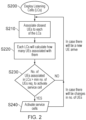
- FIG. 2 shows a flow chart for a Radio Frequency (RF) clustering methodology which can be utilised to determine where service cells in a service area should be provided.
- An initial step (S200) illustrates the deployment of listening cells 130 over a service area based on a regular hexagonal grid. This helps makes sure that the LCs cover an entire (or desired proportion of a) service area.
- step S210 the UEs associate with the closest/strongest signal LC around them. This process is illustrated more clearly in Figure 3 . With respect to Figure 3 the interaction and control message exchanges between a UE node 120 and a LC node 130 of a communication network during an association process are shown.
- Each LC broadcasts a beacon signal 300 so that the UEs can be associated with an LC.
- a UE will first identify which LC is the closest to it by determining which LC provides a highest received power level (Pr). Subsequently the UE sends a request 310 for connection to the LC with the strongest Pr.
- the LC will check the CNR level of the requesting UE to see if its CNR satisfies a predetermined threshold value. Aptly the threshold value is 9dB. This threshold will form a cluster and will later help form a cell boundary. If the CNR is sufficient then the LC will accept the request to associate and will send a successful acknowledgement message 320.
- the UEs in an LC are then clustered together by connecting to the same LC with each LC knowing precisely the number of UEs in its associated cluster.
- each LC calculates how many UEs are associated with that particular LC.
- the UE association is counted based on a counter function using the CNR of individual association messages as follows:
- k is the number of an LC and "Counter” is a vector of the number of UE associated for each LC.
- the LCs thus have information on how many UEs are clustered in their respective cell coverage area. They then check (illustrated by step S230 in Figure 2 ) how many UEs are clustered in their coverage area. They then check to see if they meet the requirement to activate a service cell. That is to say a determination is made as to whether a number of UE in a cell is greater than or equal to a minimum number of UE required per cell. All the processing can be carried out in the RF clustering unit in Figure 5 . For example the minimum requirement may be three UE. Aptly as an alternative the number is twenty UE. If the threshold requirement is met then one or more service cells are activated (illustrated in Figure 2 via step S240) accordingly.
- a service cell is activated in the service area for each listening cell which qualifies (in this described example by having a number of associated UEs that at least met a minimum threshold value).
- an option is to use the previous geographical centre of the preceding listening cell to become the new beam pointing coordinates for the service cell.
- service cells can be different depending upon the specific requirement for telecommunication operators. For example, minimum users per cell requirements may be considered or priority based requirements (cell with highest number of user will activate first). Alternatively users with priority user equipment can be utilised to help in the decision making as to where one or more service cells are to be activated. Such priority user equipment may be associated with emergency service providers or those who pay more for a higher quality of service (QoS). This helps maximise a number of users and a number of priority users served within a service area. This can be useful when a power constraint is in place.
- QoS quality of service
- Figure 2 thus helps illustrate how the provision of service cells can be an iterative process subsequent to initial provision. That is to say if numbers of UEs in original listening cell areas did not meet a predetermined threshold, the listening cells can subsequently be created again and checked to see if user equipment has migrated into the new geographical area. This may be constantly repeated periodically or randomly or repeated upon the detection of a particular event occurring.
- FIG. 4 illustrates a HAP 100 in more detail and illustrates how a directional antenna such as a phased array antenna 110 can be utilised to provide service cells 140 within a service area 400.
- the service area 400 is associated with a geographical extent.
- the HAP 100 includes a phased array controller unit 410 which can be utilised to control transmission and reception of the various antenna elements of the phased array antenna 110 to create cells and perform bi-directional communication with user equipment in the service area.
- the HAP 100 is connected via a backhaul link 420 to a ground station 430. This link may optionally be provided via a fixed cable link.
- the backhaul link 420 is provided by a wireless communication link (e.g.
- the ground station 430 is connected to a core network via a ground based cell processing centre.
- Each ground station 430 includes a directional antenna for the backhaul link 420 and the ground station can relay, using a wireless or wired connection, user data and control information between every HAP and the cell processing centre 435.
- the processing centre may be located adjacent to or be part of the ground station or may be connected to the ground station via a wired connection.
- a wireless connection can connect the ground station/s to the processing centre.
- the processing centre 435 includes at least one interface 437 with a core network 440 via a respective wired or wireless connection 441.
- the processing centre 435 can include a beam forming control unit that runs processes for controlling the flight of each aerial vehicle (such as location flight path and/or altitude). Alternatively much of the processing can be carried out on each individual HAP via a processor.
- a processing element may be a processor. This is used to indicate a central processing unit (CPU) or electronic circuit within a computer or a computer configured to carry out instructions of a computer programme. It will be understood in what follows that stating that a processor implements an action or that the processor is configured to implement an action is analogous to stating that the processor is configured to execute computer readable instructions and implement or execute an action. It is likewise to be understood that the term "computer” is intended to mean an assembly of components e.g.
- processors memory element, input device and output device arranged to receive inputs, produce outputs, store information and algorithms and execute instructions. It is not intended to be limited to any specific arrangement or group of components.
- the processor may optionally be a general purpose processor, co-processor or special-purpose processor such as, for example, a network or communication processor, compression engine, high throughput many integrated core co-processor, embedded processor or the like.
- the processor may be implanted on one or more chips. The chips can be proximate to one another or interconnected at different locations.
- the processor may be a part of and/or may be implemented on one or more substrates using any number of processed technologies, such as, for example, BiCMOS, CMOS or EMOS.
- FIG 4 helps illustrate how the HAP 100 is associated with multiple aerial Evolved Node Bs (eNodeBs) comprising a physical layer and data link layer.
- the physical layer and data link layers have several components, which can be placed together in one place either on an aerial vehicle or on the ground, or partly on the aerial vehicle and partly on the ground depending on whether it is a conventional HAP based system (all BBU components are on the aerial vehicle), or Cloud RAN (C-RAN) based system (all BBU components are on the ground), or a C-RAN system with a network functional split (part of BBU is on the aerial vehicle and on the ground).
- eNodeBs aerial Evolved Node Bs
- the backhaul link is considered as a backhaul link for a HAP based system, or as a fronthaul link for a C-RAN based system.
- Figure 4 illustrates the HAP being associated with k eNodeBs 450 1,2... k.
- the phased array controller 410 receives the respective signals for each eNodeB via a cell mapping controller 455 which receives raw IQ samples representing an individual beam, which are mapped to the designated eNode B.
- the cell mapping controller receives signals from and provides data and/or control signals to a beam forming processor 460.
- the beam forming processor 460 provides data and/or control signals to and receives signals from a clustering unit 470.
- the beam forming processor 460 also provides data and/or control signals to and receives signals from a signal processing unit 480 which provides data and/or control signals to the directional antenna 110.
- the phased array controller 410 is part of a remote radio head (RRH) which deals with processing of data coming in and out of the array antenna.
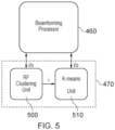
- the clustering unit 470 includes two different sub-units which may be referred to as an RF clustering unit and a K-means unit. This is illustrated more in Figure 5 .
- the RF clustering unit 500 within the clustering unit 470 of the phased array controller unit 410 receives information such as the UEs CNR levels and also processes connection requests.
- the RF clustering unit 500 transmits information about the LCs that are activated as service cells and also the UEs that are clustered in any LC.
- the RF clustering unit will transmit co-ordinates to a K-means unit 510.
- the K-means unit 510 helps optimise beam pointing co-ordinates.
- an LC passes the requirement to activate as a service cell the LC will be activated as a service cell.
- a location of the centre of a successful LC can be optimised before deploying a service cell. This can be achieved using a clustering like methodology.
- An example of a clustering algorithm is a K-means clustering algorithm.
- K-means clustering An example of K-means clustering is explained in " Antenna Platform and Terrestrial Coexistence Using K-means Clustering" 2017 IEEE 13th Malaysia International Conference on Communications 28-30 Nov 2017 by Zakaria et al which is incorporated herein by reference.
- the K-means clustering algorithm is used as an example to optimise beam pointing co-ordinates using a mean of the clustered UE positions.
- a centre of the LC is used as an initial centroid. This is illustrated in Figure 6 in more detail via step S600.
- Figure 6 illustrates an iterative process by which new co-ordinates can be determined for a centre of a cell.
- the optimisation process for each cell is carried out in sequence so that earlier optimised can act as a benchmark to determine whether the current centroid being optimised is interfering (by checking cluster-edge CINR threshold) with the earlier cell (now activated as a serving cell).
- K-means clustering to be effective specific locations are provided at the clustering unit and obtaining these specific locations can be achieved using the exchange process shown in more detail in Figure 8 .
- the centroid will use a successful LC co-ordinate and form a temporary cell.
- Figure 8 is a signalling exchange process between 830 and 820 which are needed in every association and clustering process.
- RF clustering the process by which the centroid formed from a localised group of UEs is moved taking into account the signal strength received from each UE at the HAP, can identify a high density user group accurately. By combining this with K-means clustering a higher accuracy can be achieved.
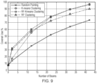
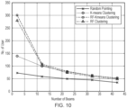
- Figure 9 and Figure 10 show results illustrating that RF and RF+K-means clustering provide a higher accuracy for spotting high density user groups compared with random pointing and K-means clustering alone.
- the graph in Figure 9 shows an RF based methodology which can cover up to 90% of population with forty-two beams. It is advantageous for K-means alone that all user locations are known that exceed a minimum CNR and CNIR threshold.
Description
- The present invention relates to a method and apparatus for providing service cells for wireless communication between user equipment and a core network. In particular, but not exclusively, the present invention relates to the initial provision of multiple listening cells, via an aerial vehicle such as a high altitude platform (HAP), followed by the provision of one or more service cells at certain locations after determining which of the initial listening cells satisfy a predetermined condition.
- The provision of wireless communication using aerial vehicles has been suggested for many years. Various types of aerial vehicles such as tethered balloons or manned aircraft or unmanned aircraft have been suggested. High altitude platforms (HAPs) have been suggested as a type of aerial vehicle. In particular the provision of high speed broadband services from HAPs has now been discussed in the prior art for a number of years. Various authors have discussed how HAPs deployed in the stratosphere around 15 to 22 km in altitude, can achieve an excellent trade off between terrestrial cellular networks and satellite based systems. HAPs have the advantage that they are capable of covering significantly wider areas with Line-of-Sight (LoS) communication links compared with terrestrial systems yet do not suffer from capacity and propagation delay limitations typically provided by satellite based systems. For example, geostationary satellites are located approximately 1800 x further from the earth's surface than HAPs.
- Wireless networks are required to deliver high aggregate data rates within a limited bandwidth through efficient spectral use. A way this can be achieved is to use directional antennas on each HAP. For example, it has been suggested that user equipment such as mobile phones, tablets or laptops or other such user devices can communicate wirelessly with a number of HAPs equipped with directional antennas such as horn or multi-element phased array antennas. These antennas can be utilised to form beams towards the ground thus illuminating "cells" that can be perceived by the user equipment as conventional terrestrial cells. An advantage of this approach relative to non-aerial vehicle based communication networks is that the locations and density of cells created by the HAPs are dynamically controllable and do not involve changes to the infrastructure on the ground.
- The publication, ZAKARIA MUHAMMAD D ET AL, "Antenna array beamforming strategies for high altitude platform and terrestrial coexistence using K-means clustering", 2017 IEEE 13TH MALAYSIA INTERNATIONAL CONFERENCE ON COMMUNICATIONS (MICC), IEEE, (20171128), investigates suitable strategies for cell deployment from a High Altitude Platform system to provide efficient delivery of coverage and capacity while giving protection for terrestrial users sharing a common 2.6 GHz band.
-
US patent number 9,913,278 - Conventionally subsequent to the provision of cells, user equipment in a service area provided by those cells needs to be associated with the cells. Conventional cell associated procedures can be inefficient and can put a limiting drain on the resources of a HAP based system. For example, available power and possible capacity limits can be reached.
- The invention is set out in the independent claims.
- It is an aim of the present invention to at least partly mitigate one or more of the above-mentioned problems.
- It is an aim of certain embodiments of the present invention to provide a method and apparatus for providing service cells for wireless communication between user equipment and a core network.
- It is an aim of certain embodiments of the present invention to make use of antenna beam pointing from an aerial vehicle such as a high altitude platform (HAP) whereby a method of understanding where to point beams is utilised in order to maximise useful coverage, capacity and capacity density of a communication system.
- It is an aim of certain embodiments of the present invention to provide an aerial vehicle such as a high altitude platform (HAP) which delivers an antenna beam pointing methodology that accommodates desired numbers of users or priorities of users to create service cells where needed.
- According to a first aspect of the present invention there is provided a method of providing service cells for wireless communication between user equipment and a core network, comprising the steps of:
- providing a plurality of listening cells across a service area associated with an aerial vehicle;
- each listening cell covering at least a portion of the service area;
- associating user equipment located in the service area with at least one listening cell;
wherein associating the user equipment comprises:- determining at least one parameter associated with a wireless signal transmitted from the aerial vehicle to the user equipment; and
- responsive to the parameter, providing an association request signal from the user equipment to the aerial vehicle;
- determining which listening cells are qualifying listening cells that are listening cells that satisfy at least one predetermined condition; and
- subsequently providing at least one service cell in the service area for each qualifying listening cell;
wherein providing the at least one service cell comprises activating the service cell for each qualifying listening cell. - Aptly the step of providing at least one service cell comprises, for each qualifying listening cell, activating a service cell having an associated service cell coverage area centred proximate to a respective centre of a listening cell cell coverage area of the qualifying listening cell.
- Aptly the step of determining which listening cells are qualifying listening cells comprises determining how many user equipment are associated with each listening cell and for each listening cell, determining if a number of associated user equipment satisfies at least one predetermined condition.
- Aptly the predetermined condition is that the number of user equipment is equal to or greater than a predetermined minimum number or that the number is high enough to make the cell a cell with a qualifyingly high number of user equipment or that the number of user equipment is equal to or greater than a predetermined proportion of total user equipment located in the service area.
- Aptly the method further provides the wireless signal by broadcasting respective beacon signals from the aerial vehicle for each listening cell.
- Aptly the method further comprises determining the at least one parameter by determining a signal strength of each received wireless signal at each user equipment and for each user equipment, providing an associated request signal to the listening cell that is associated with a wireless signal that has a greatest signal strength of all wireless signals received at the user equipment.
- Aptly the method further comprises subsequent to determining which listening cells are qualifying cells, via a clustering algorithm, determining an improved location as a centre point for a service cell associated with that listening cell, said improved location being a location geographically offset from a previously suggested centre for the listening cell and subsequently providing a service cell having an associated service cell cell coverage area centred on the improved location.
- Aptly the method further comprises determining the improved location by, via a clustering unit that performs a clustering algorithm, iteratively recalculating a proposed centre point responsive to a determined carrier to noise ratio for user equipment in a cluster edge region of a cluster of user equipment in each service cell.
- Aptly the clustering algorithm comprises a K means clustering algorithm or RF-K means clustering algorithm or RF clustering algorithm.
- Aptly the service area has an average width of 30km or more.
- Aptly the method further comprises simultaneously or one-by-one, determining which listening cells are qualifying listening cells.
- Aptly the method further comprises providing the listening cells via an aerial vehicle that is a high altitude platform (HAP).
- Aptly the HAP is at an altitude of 15 to 30km above sea level.
- Aptly the method further comprises providing the listening cells by dynamically directing a respective beam from the aerial vehicle at a plurality of respective target locations within the service area.
- Aptly the method further comprises determining a placement and/or a shape of each of the service cells responsive to at least one iterative clustering process.
- Aptly the method further comprises prioritising the provision of cell islands of cell coverage, provided by the aerial vehicle, responsive to the identification of user hot spots in the service area.
- Aptly the method further comprises prioritising a lack of provision of cell coverage, thereby providing respective islands of exclusion of cell coverage, provided by the aerial vehicle, responsive to the identification of geographical borders and/or at least one service area associated with a further communication network.
- Aptly the step of determining which cells are qualifying listening cells comprises determining if a listening cell is associated with one or more high priority user equipment and for each listening cell that is associated with at least one high priority user equipment, determining if a number of associated high priority user equipment satisfies at least one predetermined condition.
- According to a second aspect of the present invention there is provided an aerial vehicle for providing service cells for wireless communication between user equipment (UE) and a core network, comprising at least one directional antenna and a controller that includes at least one processing element for providing a plurality of listening cells across a service area associated with the aerial vehicle, each listening cell covering at least a portion of the service area, for associating user equipment located in the service area with at least one listening cell, wherein associating the user equipment comprises determining at least one parameter associated with a wireless signal transmitted from the aerial vehicle to the user equipment, and responsive to the parameter, providing an association request signal from the user equipment to the aerial vehicle, for determining which listening cells are qualifying listening cells that are listening cells that satisfy at least one predetermined condition and subsequently providing at least one service cell in the service area for each qualifying listening cell, wherein providing the at least one service cell comprises activating the service cell for each qualifying listening cell.
- Aptly the controller includes at least one processing element for each qualifying listening cell, activating a service cell having an associated service cell coverage area centred proximate to a respective centre of a listening cell coverage area of the qualifying listening cells.
- Certain embodiments of the present invention provide a method and apparatus for providing service cells for wireless communication between user equipment and a core network. By first providing a plurality of listening cells across an entire service area associated with an aerial vehicle and then determining which of those listening cells are qualifying listening cells in the sense that they satisfy a predetermined condition, one or more fully functioning service cells can subsequently be provided in the service area where needed.
- Certain embodiments of the present invention provide a method and apparatus whereby account can be taken of numbers of users in particular geographical areas (or a priority of users associated with priority user equipment in particular areas or other particular parameters) so that once identified across a service area service cells can be provided to provide wireless communication between those user equipment and a core network.
- Certain embodiments of the present invention provide for an antenna beam pointing scheme using a process which determines clusters of user equipment in geographical areas and subsequently creates service cells focussed on high density areas.
- Certain embodiments of the present invention help make use of limited resources on an aerial vehicle, such as a HAP, by prioritising islands of coverage delivered from a HAP by focussing on user hotspots. Alternatively, islands of exclusion can be prioritised to assist with coexistence with terrestrial and other systems. Still furthermore as an alternative, methodologies can be provided to help prioritise throughput and throughput density.
- Certain embodiments of the present invention provide for an antenna beam pointing process which can be used on a high altitude platform (HAP) and/or other forms of lower altitude airborne platforms.
- Certain embodiments of the present invention provide for one or more HAPS which can achieve line or sight (LoS) connectivity with terrestrial based user equipment (UE) and which can allow for rapid service deployment. A single HAP equipped with an array of antennas can deploy many beams, each of which can form a cell, and unlike in a terrestrial situation, the cells can be dynamically directed anywhere inside a geographical service area according to short or long-term fluctuations in demand.
- The invention is reflected by
Figures 1b and 1c . - Certain embodiments of the present invention will now be described hereinafter, by way of example only, with reference to the accompanying drawings in which:
-
Figure 1 graphically illustrates an RF clustering flow process; -
Figure 2 illustrates a flow chart schematically illustrating RF clustering; -
Figure 3 illustrates user equipment association with a listening cell; -
Figure 4 illustrates a HAP and a phase array controller of a HAP; -
Figure 5 illustrates apparatus to implement RF and RF + K-means clustering; -
Figure 6 illustrates how K-means clustering can be iteratively performed to obtain an optimised centroid; -
Figure 7 illustrates shifting of a centroid as two iterations of a K-means process; -
Figure 8 illustrates an information exchange between a temporary cell and a UE during an optimisation process; -
Figure 9 illustrates user proportion in terms of proportion of covered users for various schemes; and -
Figure 10 illustrates average number of users per beam for different numbers of beams deployed using different schemes. - In the drawings like reference numerals refer to like parts.
- Certain embodiments of the present invention provide for high speed broadband services from high altitude platforms (HAPs). Certain embodiments of the present invention provide for high speed broadband services from low altitude platforms (LAPs). A HAP may be an aircraft or lighter than
air structure 10 to 35 km above sea level. A LAP may be an aircraft or lighter than air structure 0.1 km to 10 km above sea level. A High Altitude Long Endurance (HALE) aircraft or free flying or tethered aerostat can be an example of a HAP. A HAP is an example of an aerial vehicle. A quadcopter or a drone are examples of LAPs. Other such aerial vehicles such as tethered vehicles or manned aircraft or the like can be utilised according to other embodiments of the present invention. Aptly each aerial vehicle is deployed at least 5 km above sea level. Aptly each LAP is deployed at least 1 km above sea level. Aptly each aerial vehicle can be deployed in the stratosphere at an altitude above sea level of around 17 to 22 km. HAPs and LAPs cover significantly wider areas with Line-of-Sight (LoS) links compared to conventional terrestrial systems and do not suffer from capacity and propagation delay limitations associated with satellites. -
Figure 1 illustrates how at least one aerial vehicle 100 (one HAP shown inFigure 1 ) can provide wireless services to user equipment. A user equipment can be a mobile phone, tablet or laptop or PDA or a device that acts as a relay or the like. Each user equipment described hereinbelow, by way of example only, is a smartphone. Each aerial vehicle described hereinbelow, by way of example only, is a HAP. Each HAP shown is equipped with one or moredirectional antenna 110. Aptly each directional antenna is a multi-element phased array antenna. Such antennas and their general control is described inGB2536015 - As shown in
Figure 1 eachaerial vehicle 100 alone can form one or more beams which are directed to the ground thus illuminating 'cells'. The beams provided by a single HAP can be used to provide a single channel wireless communication link between the respective HAP and a user equipment in eachcell 130. The wireless communication link is two way or bidirectional in the sense that uplink and downlink transfer of data can be supported. Thecells 130 can be perceived by the user equipment as conventional terrestrial wireless telecommunication cells. The locations and density of cells created by the HAPs are dynamically controllable. That is to say over time the locations where cells are directed and/or numbers of cells and/or size and/or shape of cells can be modified. Optionally this is carried out in real time. Each aerial vehicle supports at least one directional antenna. InFigure 1 each vehicle supports a phasedarray antenna 110. - Optionally, a transmission antenna and a reception antenna could be utilised. Likewise horns could be used or other such transmission/reception members. Each phased array antenna can comprise an array of small antenna elements.
- Each single channel wireless communication link is formed over the channel between a single user equipment and a single HAP. The single channel communication link is provided by forming a beam, from a directional antenna of a respective aerial vehicle, towards the ground that illuminates a first cell coverage area. The first cell coverage area has a relatively wide footprint and may thus be referred to as a wide cell. Aptly the footprint has a width of greater than 500 m. The single channel communication link enables synchronisation and/or association and/or exchange of control signals between a respective user equipment and a respective HAP and a core network.
- A footprint of a first cell coverage area provided by any one HAP comprises a region where a wireless signal strength is strong enough that a user equipment located within the cell coverage area can associate with the core network via an associated wireless communication link. Aptly a footprint of a cell coverage area is a region defined by an imaginary boundary congruent with positions where a wireless signal strength of a communication link is at a predetermined threshold level lower than a maximum signal strength in the cell coverage area. Optionally the predetermined threshold is around 9dB above the noise floor.
- Certain embodiments of the present invention provide for a clustering technique which utilises an association procedure to perform efficient user clustering to enable more efficient cell formation. This helps make more efficient use of scarce resources on the HAP system such as available power and possible capacity available. As a result this helps high altitude platform systems provide better coverage and capacity to those areas most densely occupied by HAPS by providing best coordinates to point the beams at that will form the cells on the ground. Alternatively or additionally in addition to densely populated areas, areas which include one or more high priority users associated with high priority user equipment can be identified and cells provided accordingly.
-
Figure 1 illustrates a flow process for how a clustering methodology may be carried out according to certain embodiments of the present invention. That is to say how areas of relatively high density of user equipment can be determined and that determination used to thereafter provide service cells. -
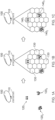
Figure 1a shows a HAP being activated (or reconfigured after an initial activation) in a particular service area. Subsequent to activation the HAP deploys listening cells (LCs) in a regular hexagonal grid to initiate a clustering process.Figure 1a illustrates threeclusters 1201-3 of user equipment arranged over a geographical area encompassed by a service area associated with the HAP. Each cluster could, for example, comprise user equipment in a small urban area or in a village or at an event such as a concert. -
Figure 1b illustrates the provision of a plurality ofLCs 130 across the service area associated with the aerial vehicle. Nineteen listening cells each having a generally hexagonal shape are shown inFigure 1 but it will be appreciated by those skilled in the art that different numbers and indeed different shapes of listening cell could be provided according to use. The user equipment in each listeningcell 130 becomes associated with a particular listening cell via a cell association procedure and this associates user equipment located in the service area with at least one listening cell. Subsequently, qualifying listening cells are determined. Qualifying listening cells are listening cells that satisfy a predetermined condition. For example, with respect toFigure 1 , qualifying listening cells are original listening cells that contain two or more user equipment associated with those listening cells. It will be appreciated by those skilled in the art that other numbers of user equipment and other conditions could be utilised to determine which listening cells are qualifying listening cells. -
Figure 1c illustrates the subsequent provision of three service cells 1401-3 in the service area. Each service cell is provided for a respective qualifying listening cell. That is to say in the example shown inFigure 1 a service cell is provided where each previously created listening cell was associated with more than two user equipment. A number of how many user equipment is associated with any one listening cell can be based upon (aggregate) received carrier to noise ratio (CNR) or through use of association control messages as described hereinbelow in more detail. Service cells 140 can be activated if there is a sufficient number of user equipment in any one listening cell whilst other originally formed listening cells may be turned off. -
Figure 2 shows a flow chart for a Radio Frequency (RF) clustering methodology which can be utilised to determine where service cells in a service area should be provided. An initial step (S200) illustrates the deployment of listeningcells 130 over a service area based on a regular hexagonal grid. This helps makes sure that the LCs cover an entire (or desired proportion of a) service area. Next, illustrated via step S210, the UEs associate with the closest/strongest signal LC around them. This process is illustrated more clearly inFigure 3 . With respect toFigure 3 the interaction and control message exchanges between aUE node 120 and aLC node 130 of a communication network during an association process are shown. Each LC broadcasts abeacon signal 300 so that the UEs can be associated with an LC. A UE will first identify which LC is the closest to it by determining which LC provides a highest received power level (Pr). Subsequently the UE sends arequest 310 for connection to the LC with the strongest Pr. The LC will check the CNR level of the requesting UE to see if its CNR satisfies a predetermined threshold value. Aptly the threshold value is 9dB. This threshold will form a cluster and will later help form a cell boundary. If the CNR is sufficient then the LC will accept the request to associate and will send asuccessful acknowledgement message 320. The UEs in an LC are then clustered together by connecting to the same LC with each LC knowing precisely the number of UEs in its associated cluster. - Returning to
Figure 2 following a step S220 is illustrated whereby each LC calculates how many UEs are associated with that particular LC. The UE association is counted based on a counter function using the CNR of individual association messages as follows:
      Counter(1:k) = 0;
      i=1;
      While (i < k)
      {
        For j = 1:1:(no. of UE)
        {
                If (index of max CNR(j,:) is i & CNR(j,i) ≥ 9dB)
                      Counter (i) ++;
                End
        }
       End
       i++;
       }
       End
Claims (15)
- A method of providing service cells (1401, 1402, 1403) for wireless communication between user equipment and a core network, comprising the steps of:providing a plurality of listening cells (130) across a service area associated with an aerial vehicle (HAP, 100);each listening cell covering at least a portion of the service area;associating user equipment located in the service area with at least one listening cell;wherein associating the user equipment comprises:determining at least one parameter associated with a wireless signal transmitted from the aerial vehicle to the user equipment; andresponsive to the parameter, providing an association request signal from the user equipment to the aerial vehicle;determining which listening cells are qualifying listening cells that are listening cells that satisfy at least one predetermined condition; andsubsequently providing at least one service cell in the service area for each qualifying listening cell;wherein providing the at least one service cell comprises activating (S240) the service cell for each qualifying listening cell.
- The method as claimed in claim 1, whereby the step of providing at least one service cell comprises:
for each qualifying listening cell, activating a service cell having an associated service cell cell coverage area centred proximate to a respective centre of a listening cell cell coverage area of the qualifying listening cell. - The method as claimed in claim 1 or claim 2, whereby the step of determining which listening cells are qualifying listening cells comprises:determining how many user equipment are associated with each listening cell; andfor each listening cell, determining if a number of associated user equipment satisfies at least one predetermined condition.optionally the predetermined condition is that the number of user equipment is equal to or greater than a predetermined minimum number or that the number is high enough to make the cell a cell with a qualifyingly high number of user equipment or that the number of user equipment is equal to or greater than a predetermined proportion of total user equipment located in the service area.
- The method as claimed in claim 1, further comprising:
providing the wireless signal by broadcasting respective beacon signals from the aerial vehicle for each listening cell. - The method as claimed in any of claims 1 to 4, further comprising:determining the at least one parameter by determining a signal strength of each received wireless signal at each user equipment; andfor each user equipment, providing an associated request signal to the listening cell that is associated with a wireless signal that has a greatest signal strength of all wireless signals received at the user equipment.
- The method as claimed in any preceding claim, further comprising:
subsequent to determining which listening cells are qualifying listening cells, via a clustering algorithm, determining an improved location as a centre point for a service cell associated with that listening cell, said improved location being a location geographically offset from a previously suggested centre for the listening cell; and subsequently providing a service cell having an associated service cell cell coverage area centred on the improved location , optionally further comprising:
determining the improved location by, via a clustering unit that performs a clustering algorithm, iteratively recalculating a proposed centre point responsive to a determined carrier to noise ratio for user equipment in a cluster edge region of a cluster of user equipment in each service celloptionally the clustering algorithm comprises a K means clustering algorithm or RF-K means clustering algorithm or RF clustering algorithm. - The method as claimed in any preceding claim, further comprising:
the service area has an average width of 30 km or more. - The method as claimed in any preceding claim, further comprising:
simultaneously or one-by-one, determining which listening cells are qualifying listening cells. - The method as claimed in any preceding claim, further comprising:
providing the listening cells via an aerial vehicle that is a high altitude platform, HAP, optionally the HAP is at an altitude of 15 to 30 km above sea level. - The method as claimed in any preceding claim, further comprising:
providing the listening cells by dynamically directing a respective beam from the aerial vehicle at a plurality of respective target locations within the service area. - The method as claimed in any preceding claim, further comprising:
determining a placement and/or a shape of each of the service cells responsive to at least one iterative clustering process. - The method as claimed in any preceding claim, further comprising:
prioritising the provision of cell islands of cell coverage, provided by the aerial vehicle, responsive to the identification of user hot spots in the service area. - The method as claimed in any one of claims 1 to 11, further comprising:
prioritising a lack of provision of cell coverage, thereby providing respective islands of exclusion of cell coverage, provided by the aerial vehicle, responsive to the identification of geographical borders and/or at least one service area associated with a further communication network. - The method as claimed in claim 1 or claim 2, whereby the step of determining which cells are qualifying listening cells comprises:determining if a listening cell is associated with one or more high priority user equipment; andfor each listening cell that is associated with at least one high priority user equipment, determining if a number of associated high priority user equipment satisfies at least one predetermined condition.
- An aerial vehicle for providing service cells for wireless communication between user equipment, UE, and a core network, comprising:at least one directional antenna; anda controller that includes at least one processing element for providing a plurality of listening cells across a service area associated with the aerial vehicle, each listening cell covering at least a portion of the service area, for associating user equipment located in the service area with at least one listening cell, wherein associating the user equipment comprises determining at least one parameter associated with a wireless signal transmitted from the aerial vehicle to the user equipment, and responsive to the parameter, providing an association request signal from the user equipment to the aerial vehicle, for determining which listening cells are qualifying listening cells that are listening cells that satisfy at least one predetermined condition and subsequently providing at least one service cell in the service area for each qualifying listening cell, wherein providing the at least one service cell comprises activating the service cell for each qualifying listening cell.
Applications Claiming Priority (2)
| Application Number | Priority Date | Filing Date | Title |
|---|---|---|---|
| GBGB1901060.2A GB201901060D0 (en) | 2019-01-25 | 2019-01-25 | Service cell selection |
| PCT/GB2020/050164 WO2020152475A1 (en) | 2019-01-25 | 2020-01-24 | Service cell selection |
Publications (2)
| Publication Number | Publication Date |
|---|---|
| EP3915293A1 EP3915293A1 (en) | 2021-12-01 |
| EP3915293B1 true EP3915293B1 (en) | 2024-03-20 |
Family
ID=65656014
Family Applications (1)
| Application Number | Title | Priority Date | Filing Date |
|---|---|---|---|
| EP20705450.3A Active EP3915293B1 (en) | 2019-01-25 | 2020-01-24 | Service cell selection |
Country Status (4)
| Country | Link |
|---|---|
| US (1) | US20230163833A1 (en) |
| EP (1) | EP3915293B1 (en) |
| GB (1) | GB201901060D0 (en) |
| WO (1) | WO2020152475A1 (en) |
Family Cites Families (4)
| Publication number | Priority date | Publication date | Assignee | Title |
|---|---|---|---|---|
| US9718557B2 (en) * | 2014-01-17 | 2017-08-01 | The Research Foundation For The State University Of New York | Flight data tracker |
| US9398467B2 (en) * | 2014-09-05 | 2016-07-19 | Verizon Patent And Licensing Inc. | System and method for providing extension of network coverage |
| GB2536015A (en) | 2015-03-03 | 2016-09-07 | Stratospheric Platforms Ltd | Process and apparatus for communicating with a user antenna |
| US9913278B2 (en) * | 2016-06-06 | 2018-03-06 | Google Llc | Systems and methods for dynamically allocating wireless service resources consonant with service demand density |
-
2019
- 2019-01-25 GB GBGB1901060.2A patent/GB201901060D0/en not_active Ceased
-
2020
- 2020-01-24 EP EP20705450.3A patent/EP3915293B1/en active Active
- 2020-01-24 WO PCT/GB2020/050164 patent/WO2020152475A1/en unknown
- 2020-01-24 US US17/310,208 patent/US20230163833A1/en active Pending
Also Published As
| Publication number | Publication date |
|---|---|
| US20230163833A1 (en) | 2023-05-25 |
| WO2020152475A1 (en) | 2020-07-30 |
| GB201901060D0 (en) | 2019-03-13 |
| EP3915293A1 (en) | 2021-12-01 |
Similar Documents
| Publication | Publication Date | Title |
|---|---|---|
| EP3651381B1 (en) | System for providing high speed communications service in an airborne wireless cellular network | |
| He et al. | Joint altitude and beamwidth optimization for UAV-enabled multiuser communications | |
| CN107018514B (en) | Spectrum sharing between aircraft-based air-to-ground communication systems and existing geostationary satellite services | |
| US9866312B2 (en) | Beam forming and pointing in a network of unmanned aerial vehicles (UAVs) for broadband access | |
| EP3309976B1 (en) | Method for managing wireless communications links between an airborne communication terminal and a plurality of user terminals, one of them being used as relay between the terminals. | |
| AU2017291705B2 (en) | Servicing cell selection in air to ground communication systems | |
| US6735438B1 (en) | Antenna for air-to-ground communication | |
| Shibata et al. | System design of gigabit HAPS mobile communications | |
| US8810451B2 (en) | Communication antenna automatic orientation apparatus and method | |
| US20170237482A1 (en) | Multibeam coverage for a high altitude platform | |
| KR101822369B1 (en) | High-capacity hybrid terrestrial/satellite cellular radio communication system | |
| US10194335B2 (en) | Wireless communication method using hybrid beamforming and apparatus therefore | |
| KR101854899B1 (en) | Communication method and bean forming apparatus in a multi-cell mobile communication system | |
| JP2001522160A (en) | Non-terrestrial cellular mobile telecommunications station | |
| CA3127655C (en) | Systems and methods of adaptive beamforming for mobile satellite systems based on user locations and co-channel waveforms | |
| JP2021093761A (en) | Method for connection establishment using common random access preamble | |
| CN113573318A (en) | Spectrum use method, system, antenna and network equipment | |
| US11146326B1 (en) | Reconfigurable and prioritizable wireless radio system for providing massive bandwidth to the sky using a limited number of frequencies and adaptable hardware | |
| EP3915293B1 (en) | Service cell selection | |
| CN107547114B (en) | SDM/SDMA communication method for adjusting point beam antenna direction packet by packet | |
| US8571499B1 (en) | Wireless terrestrial communications systems using a line-of-sight frequency for inbound data and a non-line-of-sight frequency for outbound data | |
| WO2024008518A1 (en) | Interference-limited transmission from access points |
Legal Events
| Date | Code | Title | Description |
|---|---|---|---|
| STAA | Information on the status of an ep patent application or granted ep patent |
Free format text: STATUS: UNKNOWN |
|
| STAA | Information on the status of an ep patent application or granted ep patent |
Free format text: STATUS: THE INTERNATIONAL PUBLICATION HAS BEEN MADE |
|
| PUAI | Public reference made under article 153(3) epc to a published international application that has entered the european phase |
Free format text: ORIGINAL CODE: 0009012 |
|
| STAA | Information on the status of an ep patent application or granted ep patent |
Free format text: STATUS: REQUEST FOR EXAMINATION WAS MADE |
|
| 17P | Request for examination filed |
Effective date: 20210715 |
|
| AK | Designated contracting states |
Kind code of ref document: A1 Designated state(s): AL AT BE BG CH CY CZ DE DK EE ES FI FR GB GR HR HU IE IS IT LI LT LU LV MC MK MT NL NO PL PT RO RS SE SI SK SM TR |
|
| DAV | Request for validation of the european patent (deleted) | ||
| DAX | Request for extension of the european patent (deleted) | ||
| RIC1 | Information provided on ipc code assigned before grant |
Ipc: H04W 16/24 20090101ALN20230904BHEP Ipc: H04W 16/28 20090101ALN20230904BHEP Ipc: H04W 16/10 20090101ALN20230904BHEP Ipc: H04W 84/06 20090101ALN20230904BHEP Ipc: H04B 7/185 20060101ALI20230904BHEP Ipc: H04W 16/26 20090101ALI20230904BHEP Ipc: H04W 24/02 20090101AFI20230904BHEP |
|
| GRAP | Despatch of communication of intention to grant a patent |
Free format text: ORIGINAL CODE: EPIDOSNIGR1 |
|
| STAA | Information on the status of an ep patent application or granted ep patent |
Free format text: STATUS: GRANT OF PATENT IS INTENDED |
|
| INTG | Intention to grant announced |
Effective date: 20231013 |
|
| GRAS | Grant fee paid |
Free format text: ORIGINAL CODE: EPIDOSNIGR3 |
|
| GRAA | (expected) grant |
Free format text: ORIGINAL CODE: 0009210 |
|
| STAA | Information on the status of an ep patent application or granted ep patent |
Free format text: STATUS: THE PATENT HAS BEEN GRANTED |
|
| AK | Designated contracting states |
Kind code of ref document: B1 Designated state(s): AL AT BE BG CH CY CZ DE DK EE ES FI FR GB GR HR HU IE IS IT LI LT LU LV MC MK MT NL NO PL PT RO RS SE SI SK SM TR |
|
| REG | Reference to a national code |
Ref country code: GB Ref legal event code: FG4D |
|
| REG | Reference to a national code |
Ref country code: CH Ref legal event code: EP |
|
| REG | Reference to a national code |
Ref country code: DE Ref legal event code: R096 Ref document number: 602020027486 Country of ref document: DE |