EP3914957B1 - Adjustment mechanism for head-mounted display - Google Patents
Adjustment mechanism for head-mounted display Download PDFInfo
- Publication number
- EP3914957B1 EP3914957B1 EP20722053.4A EP20722053A EP3914957B1 EP 3914957 B1 EP3914957 B1 EP 3914957B1 EP 20722053 A EP20722053 A EP 20722053A EP 3914957 B1 EP3914957 B1 EP 3914957B1
- Authority
- EP
- European Patent Office
- Prior art keywords
- actuator
- lead screw
- movement mechanism
- dynamic event
- nut assembly
- Prior art date
- Legal status (The legal status is an assumption and is not a legal conclusion. Google has not performed a legal analysis and makes no representation as to the accuracy of the status listed.)
- Active
Links
Images



Classifications
-
- G—PHYSICS
- G02—OPTICS
- G02B—OPTICAL ELEMENTS, SYSTEMS OR APPARATUS
- G02B27/00—Optical systems or apparatus not provided for by any of the groups G02B1/00 - G02B26/00, G02B30/00
- G02B27/01—Head-up displays
- G02B27/0149—Head-up displays characterised by mechanical features
-
- G—PHYSICS
- G02—OPTICS
- G02B—OPTICAL ELEMENTS, SYSTEMS OR APPARATUS
- G02B27/00—Optical systems or apparatus not provided for by any of the groups G02B1/00 - G02B26/00, G02B30/00
- G02B27/01—Head-up displays
- G02B27/0179—Display position adjusting means not related to the information to be displayed
-
- G—PHYSICS
- G02—OPTICS
- G02B—OPTICAL ELEMENTS, SYSTEMS OR APPARATUS
- G02B27/00—Optical systems or apparatus not provided for by any of the groups G02B1/00 - G02B26/00, G02B30/00
- G02B27/01—Head-up displays
- G02B27/017—Head mounted
- G02B27/0172—Head mounted characterised by optical features
-
- G—PHYSICS
- G02—OPTICS
- G02B—OPTICAL ELEMENTS, SYSTEMS OR APPARATUS
- G02B27/00—Optical systems or apparatus not provided for by any of the groups G02B1/00 - G02B26/00, G02B30/00
- G02B27/01—Head-up displays
- G02B27/0149—Head-up displays characterised by mechanical features
- G02B2027/0154—Head-up displays characterised by mechanical features with movable elements
-
- G—PHYSICS
- G02—OPTICS
- G02B—OPTICAL ELEMENTS, SYSTEMS OR APPARATUS
- G02B27/00—Optical systems or apparatus not provided for by any of the groups G02B1/00 - G02B26/00, G02B30/00
- G02B27/01—Head-up displays
- G02B27/0179—Display position adjusting means not related to the information to be displayed
- G02B2027/0181—Adaptation to the pilot/driver
Definitions
- This disclosure relates to a display system and, in particular, a head-mounted display and an adjustment mechanism therefor.
- Head-mounted displays are electronic devices that display graphics to a user wearing the head-mounted display, for example, when participating in activities related to computer-generated, augmented, virtual, and/or mixed realities.
- the head-mounted display may be worn by users having differing head sizes and facial features, so the ability to adjust a fit of the head-mounted display for a particular user having specific features is a high priority.
- Existing head-mounted displays can be adjusted for circumferential fit using features such headbands made from elastic materials and temple-located adjustment mechanisms that change a length of a non-elastic headband between a variety of predetermined lengths.
- these adjustment options do not address differences in facial features, such as different inter-pupillary distances (IPD) among users.
- IPD inter-pupillary distances
- US 2015103306 is directed to a VR headset with an adjustment mechanism coupled to eyepieces of the headset and operable to simultaneously move the eyepieces. It describes a knob-based adjustment mechanism with a linear actuator 560 and bar linkages 562a,b.
- the adjustment mechanism allows a user to manipulate the interpupillary distance by moving the eyepieces inwardly or outwardly relative to the adjustment mechanism. The user rotates the knob-based adjustment mechanism in a clockwise direction which causes a linear extension of the linear actuator device shaft.
- US 2001055947 is directed to a damper assembly in which the position of the damper blades is controlled by an electric powered actuator.
- the powered actuator rotates a threaded lead screw shaft attached to an operator means attached to the damper blades of the damper. It describes a spring means 35 that acts on the damper doors, such as of a vent.
- a head-mounted display includes an optical assembly and an actuator.
- the actuator includes a movement mechanism configured to adjust a position of an optical component within the optical assembly, a locking-release mechanism configured to modify operation of the movement mechanism upon detection of a dynamic event, and a dampening mechanism configured to control positional changes of the optical component during the dynamic event.
- the movement mechanism can be configured to adjust the position of the optical component within the optical assembly to a pre-dynamic event position in accordance with detection of an end of the dynamic event.
- the movement mechanism can comprise a lead screw and a nut assembly, the nut assembly configured to translate along the lead screw based on rotation of the lead screw.
- the nut assembly can comprise separable first and second portions, and the locking-release mechanism can include a spring that linearly biases one of the first and second portions of the nut assembly against the lead screw.
- the modified operation of the movement mechanism can include one of the first and second portions of the nut assembly being disengaged from the lead screw.
- the dampening mechanism can comprise an electromagnetic component configured to generate attraction between the nut assembly and the lead screw during the dynamic event.
- the movement mechanism can comprise a lead screw and a plate configured to translate along the lead screw based on rotation of the lead screw.
- the locking-release mechanism can include a spring that torsionally biases the plate against the lead screw. Modified operation of the movement mechanism can include the plate being disengaged from the lead screw.
- the dampening mechanism can comprise an electromagnetic component configured to generate attraction between the plate and the lead screw during the dynamic event.
- the dampening mechanism can comprise an electromagnetic component configured to repel the movement mechanism from end portions of the actuator during the dynamic event.
- the dampening mechanism can comprise a spring or cable configured to restrict motion of the movement mechanism during the dynamic event.
- a method in a second aspect, includes detecting, using a sensor in a head-mounted display, a start of a dynamic event. I accordance with detection of the start of the dynamic event and using a locking-release mechanism, the method includes modifying operation of a movement mechanism. The movement mechanism is configured to adjust a position of an optical component within an optical assembly of the head-mounted display. The method includes detecting, using the sensor in the head-mounted display, an end of the dynamic event. In accordance with detection of the end of the dynamic event and using the movement mechanism, the method includes adjusting the position of the optical component within the optical assembly to a pre-dynamic event position.
- the method can include controlling positional changes of the movement mechanism during the dynamic event.
- the dampening mechanism can comprise an electromagnetic component configured to repel components within the movement mechanism during the dynamic event.
- the dampening mechanism can comprise an electromagnetic component configured to cause attraction between components within the movement mechanism during the dynamic event.
- the dampening mechanism can comprise a spring or cable configured to restrict motion of the movement mechanism during the dynamic event.
- the movement mechanism can comprise a lead screw and a nut assembly nut assembly configured to translate along the lead screw based on rotation of the lead screw.
- the nut assembly can comprise separable first and second portions.
- the locking-release mechanism can include a spring that linearly biases one of the first and second portions of the nut assembly against the lead screw. Modified operation of the movement mechanism can include one of the first and second portions of the nut assembly being disengaged from the lead screw.
- the movement mechanism can comprise a lead screw and a plate configured to translate along the lead screw based on rotation of the lead screw.
- the locking-release mechanism can include a spring that torsionally biases the plate against the lead screw. Modified operation of the movement mechanism can include the plate being disengaged from the lead screw.
- the second aspect may include any combination of the features described in this paragraph.
- an actuator in a third aspect, includes a movement mechanism configured to adjust a position of an optical component within an optical assembly of a head-mounted display.
- the movement mechanism includes a lead screw and a threaded component.
- the threaded component is configured to translate along the lead screw based on rotation of the lead screw.
- the actuator also includes a locking-release mechanism configured to modify operation of the movement mechanism upon detection of a dynamic event.
- the locking-release mechanism includes a spring configured to bias the threaded component against the lead screw. Modified operation of the movement mechanism includes the threaded component being disengaged from the lead screw.
- the actuator also includes a dampening mechanism configured to control positional changes of the movement mechanism during the dynamic event.
- the dampening mechanism can comprise an electromagnetic component configured to generate attraction between the threaded component and the lead screw during the dynamic event.
- the dampening mechanism can comprise an electromagnetic component configured to repel the movement mechanism from end portions of the actuator during the dynamic event.
- the third aspect may include any combination of the features described in this paragraph.
- head-mounted displays require the alignment of optical components such as lenses, projection units, displays, screens, etc. to unique facial features among a variety of users in order to promote comfort, fit, performance, etc.
- optical components can be physically repositioned in respect to other components within a head-mounted display.
- physical repositioning mechanisms should be small in size with tightly controlled motion, for example, small electro-mechanical actuators. Though small in size, the actuators should be able to withstand dynamic events and properly function after experiencing these dynamic events. Dynamic events can include shaking, jostling, dropping, impacting, or otherwise handling the head-mounted display in a manner that leads to forces being exerted upon optical components or subcomponents within the electro-mechanical actuators.
- locking-release mechanisms that allow disengagement or slip along the lead screw can be used in conjunction with dampening mechanisms that allow controlled sliding and/or stopping along a guide rail to prevent damage both to the actuator and to the optical components that undergo motion through use of the actuator.
- the locking-release and dampening mechanisms can include motor-driven, lead-screw system designs that leverage linear spring-loaded nut assemblies, torsional spring-loaded plates, drop-detection-based lock engagement or disengagement, and optical-component motion dampening during dynamic events. Detailed descriptions of these and other applicable mechanisms that improve performance of physical repositioning within a head-mounted display are described herein.
- FIG. 1 is a top view of a head-mounted display 100 that includes a display assembly 102 and a head support 104.
- the display assembly 102 can include a housing 106 and various sub-assemblies and electronics therein, such as one or more optical assemblies 108, 110, sensors 112 (e.g., detecting gaze and/or user status), power electronics 114, and actuators 116.
- Various portions or subcomponents of the optical assemblies 108, 110 e.g., such as lenses, projection units, screens, or displays
- the optical assemblies 108, 110, sensors 112, power electronics 114, and actuators 116 are depicted schematically and in dashed lines to illustrate being hidden from view and disposed within the display assembly 102.
- the head support 104 is coupled to left and right sides of the display assembly 102 (e.g., to the housing 106), extending rearward of the display assembly 102 and between the left and right sides thereof.
- the display assembly 102 extends across a front of the head of the user (i.e., the face of the user), while the head support 104 extends rearward along left and right sides of the head of the user and across a rear of the head of the user.
- the display assembly 102 and the head support 104 cooperatively extend around the head of the user.
- the head support 104 includes a band 118 and one or more circumferential adjustment mechanisms 120 (e.g., two as shown on the left and right sides)
- the band 118 forms a primary portion of the head support 104, which engages the head of the user to support the head-mounted display 100 worn on the head of the user.
- Each of the circumferential adjustment mechanisms 120 removably couples the head support 104 to the display assembly 102 and allows the head support 104 to change length overall by changing the length between the band 118 and the circumferential adjustment mechanisms 120. Though two circumferential adjustment mechanisms 120 are shown as acting from opposing sides of the head support 104, the head support 104 may alternatively employ a single adjustment mechanism.
- the band 118 can be elastic, flexible, or otherwise deformable to accommodate different shapes of heads of the users.
- the band 118 can be formed of or otherwise include an elastic or silicone material.
- the band 118 may also be configured to transfer electrical power from a power source (e.g., an external battery) to the display assembly 102.
- the band 118 may include a flexible circuit 122 extending from a power connector 124, through the circumferential adjustment mechanism 120, to a corresponding power connector (not shown) of the display assembly 102.
- the flexible circuit 122 (hidden and illustrated in dash-dot lines) may be embedded in the elastic or silicone material of the band 118 or otherwise hidden from view by the material of the band 118. In this manner, the band 118 may supply electrical current to the display assembly 102 inclusive of the optical assemblies 108, 110, sensors 112, power electronics 114, and actuators 116.
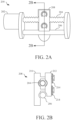
- FIGS. 2A and 2B are detail and partially-exploded sectional views of an actuator 200.
- the partially-exploded sectional view of FIG. 2B is representative of the location indicated in FIG. 2A .
- the actuator 200 may serve as the actuator 116 disposed in the head-mounted display 100 of FIG. 1 .
- the actuator 200 includes a movement mechanism formed by a motor 202, a lead screw 204, a guide rail 206, and a nut assembly 208.
- the nut assembly 208 is configured to translate along the lead screw 204 based on rotation of the lead screw 204 and thread engagement between the nut assembly 208 and the lead screw 204.
- the lead screw 204 can be rotationally driven by the motor 202 to cause translation of the nut assembly 208.
- the movement mechanism is configured to adjust a position of an optical component (e.g., a lens, a display, a projector, a screen, a lens and a display, etc., not shown) within an optical assembly (e.g., within the optical assemblies 108, 110 within the head-mounted display 100).
- the threads on the lead screw 204, the threads on the nut assembly 208, or both, can be coated to provide a longer life for the actuator 200 and to reduce friction and noise associated with operation of the actuator 200.
- Positional adjustment of optical component(s) can be achieved using the described movement mechanism, for example, by coupling the optical component(s) that require(s) repositioning to a portion of the nut assembly 208, though the coupling is not shown.
- the movement mechanism can be used to modify optical component spacing along a focal axis or modify interpupillary distance, for example, between optical assemblies within the same head-mounted display.
- the nut assembly 208 can be designed to avoid unintended rotation, for example, by use of the guide rail 206 extending parallel to the lead screw 204, though other anti-rotation features in the actuator 200 are also possible. When the guide rail 206 is used as shown in FIGS. 2A and 2B , the nut assembly 208 translates along both the lead screw 204 and the guide rail 206 based on rotation of the lead screw 204 as driven by the motor 202.
- the actuator 200 also includes a locking-release mechanism formed by separable halves or portions 210, 212 of the nut assembly 208 and one or more springs 214 that can linearly bias the portion 212 against the lead screw 204, against the guide rail 206, and against the portion 210 of the nut assembly 208 as is best seen in the partially-exploded sectional view of FIG. 2B .
- the nut assembly 208 has a split-nut configuration with the portion 212 of the nut assembly 208 configured to translate away from the portion 210 of the nut assembly 208 when a load experienced is sufficient to overcome a load generated by the springs 214 against the portion 212 of the nut assembly 208. Sufficient loads of this type can occur during dynamic events (e.g., shaking, jostling, dropping, or impacting a head-mounted display that includes the actuator 200).
- the threads on the lead screw 204 and the threads on the portions 210, 212 can be disengaged, and the nut assembly 208 becomes free to slide along the lead screw 204 and the guide rail 206, thus limiting or avoiding damage to the nut assembly 208 and/or to the lead screw 204 during the dynamic event based on operation of the described locking-release mechanism.
- the threads on the lead screw 204 and the threads on the portions 210, 212 of the nut assembly 208 can become reengaged, and the nut assembly 208 can once again be driven along the lead screw 204 by the motor.
- the nut assembly 208 may be in a different position along the lead screw 204 than prior to or during the dynamic event.
- the movement mechanism may be configured to adjust the position of the nut assembly 208, and in turn, any optical components coupled or otherwise connected to the nut assembly 208, to a pre-dynamic event position, that is, to a position that was documented for the nut assembly 208 in respect to the lead screw 204 prior to the dynamic event.
- both portions 210, 212 of the nut assembly 208 are shown as being threaded at the interface to the lead screw 204, in some examples, only the portion 212 may include threads without impacting operation of the actuator 200.
- a position sensor (not shown) can be used to determine a position of the nut assembly 208 in respect to the lead screw 204 before, during, and after a dynamic event.
- An accelerometer, inertial measurement unit, or any other sensor (not shown) can be used to determine a beginning, duration, and end of the dynamic event.
- a magnetic encoder system can include a sensor that determines a landing position of the portions 210, 212 of the nut assembly 208 in respect to the lead screw 204 (or other portion of the actuator 200), and a controller can perform a recalibration, repositioning the portions 210, 212 of the nut assembly 208 to pre-dynamic event positions along the lead screw 204 after the dynamic event.
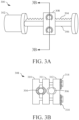
- FIGS. 3A and 3B are detail and partially-exploded sectional views of another actuator 300.
- the partially-exploded sectional view of FIG. 3B is representative of the location indicated in FIG. 3A .
- the actuator 300 may serve as the actuator 116 disposed in the head-mounted display 100 of FIG. 1 and may be similar to the actuator 200 described in respect to FIGS. 2A and 2B . Differences between the actuator 300 and the actuator 200 are highlighted herein.
- the actuator 300 includes a movement mechanism formed by a motor 302, a lead screw 304, a guide rail 306, and a nut assembly 308.
- the nut assembly 308 is configured to translate along the lead screw 304 and the guide rail 306 based on rotation of the lead screw 304 and thread engagement between the nut assembly 308 and the lead screw 304.
- the nut assembly 308 can be designed to avoid unintended rotation, for example, by use of the guide rail 306 extending parallel to the lead screw 304, though other anti-rotation features in the actuator 300 are also possible.
- the actuator 300 also includes a locking-release mechanism formed by separable portions 310, 311, 312 of the nut assembly 308 and one or more springs 314 that can linearly bias the portion 312 against the guide rail 306 and the central-most portion 311 of the nut assembly 308.
- the portion 311 can be linearly biased against the lead screw 304 and the portion 310 of the nut assembly 308 as is best seen in the partially-exploded sectional view of FIG. 3B .
- the nut assembly 308 has three portions 310, 311, 312, with the portions 311, 312 of the nut assembly 308 configured to translate away and become disengaged from the portion 310 of the nut assembly 308 when a load experienced is sufficient to overcome a load generated by the springs 314 against the portion 312 of the nut assembly 308.
- Sufficient loads of this type can occur during dynamic events (e.g., shaking, jostling, dropping, or impacting a head-mounted display that includes the actuator 300).
- the actuator 300 of FIGS. 3A and 3B differs from the actuator 200 of FIGS. 2A and 2B in that the nut assembly 308 is used in place of the nut assembly 208.
- the actuator 300 of FIGS. 3A and 3B may be useful in vertically tight packaging spaces, that is, the actuator 300 may be shorter in height than the actuator 200 due to the construction of the nut assemblies 208, 308.
- the actuator 200 of FIGS. 2A and 2B may be useful in horizontally tight packaging spaces, that is, the actuator 200 may be narrower in width than the actuator 300 due to the construction of the nut assemblies 208, 308.
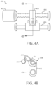
- FIGS. 4A and 4B are detail and partially-exploded sectional views of another actuator 400.
- the partially-exploded sectional view of FIG. 4B is representative of the location indicated in FIG. 4A .
- the actuator 400 may serve as the actuator 116 disposed in the head-mounted display 100 of FIG. 1 and may be similar to the actuators 200, 300 described in respect to FIGS. 2A, 2B , 3A, and 3B . Differences between the actuator 400 and the actuators 200, 300 are highlighted herein.
- the actuator 400 includes a movement mechanism formed by a motor 402, a lead screw 404, a guide rail 406, and a torsion assembly 408.
- the torsion assembly 408 is configured to translate along the lead screw 404 and the guide rail 406 based on rotation of the lead screw 404 and thread engagement between the torsion assembly 408 and the lead screw 404.
- the torsion assembly 408 can be designed to avoid unintended rotation, for example, by use of the guide rail 406 extending through the torsion assembly 408, though other anti-rotation features in the actuator 400 are also possible.
- the torsion assembly 408 includes a plate 410, a support 412, and a torsional spring 414 that can torsionally bias the plate 410 against the lead screw 404 to form a locking-release mechanism of the actuator 400.
- the torsional spring 414 acts against both the plate 410 and the support 412 such that the plate 410 is configured to rotate away and become disengaged from the lead screw 404 when a load experienced is sufficient to overcome a load generated by the spring 414 against the plate 410 and the support 412. Sufficient loads of this type can occur during dynamic events (e.g., shaking, jostling, dropping, or impacting a head-mounted display that includes the actuator 400).
- the actuator 400 of FIGS. 4A and 4B differs from the actuators 200, 300 of FIGS. 2A, 2B , 3A, and 3B in that the torsion assembly 408 with the rotatable plate 410 is used in place of the nut assemblies 208, 308.
- Use of the actuator 400 of FIGS. 4A and 4B can support unique positional relationships between the lead screw 404 and the guide rail 406 since these components can be both vertically and horizontally offset while remaining generally parallel. Further, there is less physical engagement between the plate 410 and the lead screw 404 than is present between the nut assemblies 208, 308 and the lead screws 204, 304, reducing for example, friction-based and wear-based failure potential.
- the actuators 200, 300, 400 described in respect to FIGS. 2A, 2B , 3A, 3B , 4A, and 4B include split-nut and torsional-type movement mechanisms using lead screws 204, 304, 404.
- Additional designs for movement mechanisms can include living-hinge nut assemblies and back-driveable lead screws (not shown).
- a living-hinge nut assembly can be separated along a central axis with coupled top and bottom edges such that the sides of the nut assembly disengage from the lead screw under sufficient force while the top and bottom edges remain coupled.
- a back-driveable lead screw can be controlled to reduce forces experienced during a dynamic event by enabling back-driving during the dynamic event.
- movement mechanisms may use rack-and-pinion, pneumatic, hydraulic, piezo-actuated, and electromagnetic designs (not shown) to achieve positioning and repositioning of optical components within optical assemblies.
- a consequence of using the locking-release mechanisms described in respect to FIGS. 2A, 2B , 3A, 3B , 4A, and 4B is that the nut assemblies 208, 308 and torsion assembly 408 can become generally free-sliding along the guide rails 206, 306, 406 during a dynamic event sufficient to disengage the nut assemblies 208, 308 and torsion assembly 408 from the lead screws 204, 304, 404.
- various dampening mechanisms can be implemented to control positional changes of the otherwise free-sliding optical components during dynamic events.
- FIGS. 5A and 5B are detail views of magnetic dampening mechanisms for an actuator 500 similar to the actuators 200, 300, 400 of FIGS. 2A, 2B , 3A, 3B , 4A, and 4B .
- the actuator 500 may serve as the actuator 116 disposed in the head-mounted display 100 of FIG. 1 .
- the actuator 500 includes a movement mechanism formed by a motor 502, a lead screw 504, a guide rail 506, and a nut assembly 508.
- the nut assembly 508 is configured to translate along the lead screw 504 and the guide rail 506 based on rotation of the lead screw 504 and thread engagement between the nut assembly 508 and the lead screw 504.
- Locking-release mechanisms similar to those described in reference to FIGS. 2A, 2B , 3A, and 3B can cause the nut assembly 508 to become disengaged from the lead screw 504, for example, during a dynamic event.
- the actuator 500 can include an electromagnetic dampening mechanism formed by an electromagnetic component 516 disposed within or forming a portion of the nut assembly 508 as shown in dotted line in FIGS. 5A and 5B .
- the electromagnetic dampening mechanism can include electromagnetic components 518, 520 disposed at ends of the guide rail 506 as shown in dotted line for hidden representation.
- the electromagnetic components 518, 520 can be controlled to actuate and repel the electromagnetic component 516 during a dynamic event, thus serving as cushions or bumpers to slow or prohibit the nut assembly 508 from impacting the ends of the guide rail 506 when sliding.
- the nut assembly 508 may include portions formed of ferritic or other material susceptible to magnetic repulsion, and the nut assembly 508 may be repelled by the electromagnetic components 518, 520 during dynamic events.
- the electromagnetic dampening mechanism can include electromagnetic component 522 that runs the length of the guide rail 506 as shown in dotted line.
- the electromagnetic component 522 can be controlled to actuate and attract the electromagnetic component 516 during a dynamic event, thus serving to slow motion of the nut assembly 508 during the dynamic event due to attraction between the electromagnetic components 516, 522.
- the guide rail 506 may be formed of ferritic or other material susceptible to magnetic attraction, and the electromagnetic component 516 may be attracted to the guide rail 506 during dynamic events.
- the electromagnetic components 516, 518, 520, 522 may be designed to repel in non-powered states and attract in powered states (or vice-versa), and some of the electromagnetic components 516, 518, 520, 522 may be replaced with non-powered ferritic or other magnetically-susceptible materials without changing the overall function of the dampening mechanism.
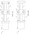
- FIG. 6A and 6B are detail views of mechanical dampening mechanisms for an actuator 600 similar to the actuators 200, 300, 500 of FIGS. 2A, 2B , 3A, 3B , 5A, and 5B .
- the actuator 600 may serve as the actuator 116 disposed in the head-mounted display 100 of FIG. 1 .
- the actuator 600 includes a movement mechanism formed by a motor 602, a lead screw 604, a guide rail 606, and a nut assembly 608.
- the nut assembly 608 is configured to translate along the lead screw 604 and the guide rail 606 based on rotation of the lead screw 604 and thread engagement between the nut assembly 608 and the lead screw 604.
- Locking-release mechanisms similar to those described in reference to FIGS. 2A, 2B , 3A, and 3B can cause the nut assembly 608 to become disengaged from the lead screw 604, for example, during a dynamic event.
- the actuator 600 can include a mechanical dampening mechanism such as those described in reference to FIGS. 6A and 6B .
- the mechanical dampening mechanism can include one or more cables 626, 628 (two are shown in solid and dotted line) disposed proximate to ends of the lead screw 604 and the guide rail 606.
- the cables 626, 628 can either wind or unwind during a dynamic event, serving to slow or counteract motion of the nut assembly 608 to avoid having the nut assembly 608 impact the ends of the lead screw 604 and guide rail 606 when sliding.
- the cables 626, 628 can be engaged under high torque conditions, or the cables 626, 628 can be designed with a predetermined amount of unwinding or stretching that occurs before stopping movement of the nut assembly 608.
- the mechanical dampening mechanism can include one or more springs 630, 632 (two are shown) disposed proximate to ends of the lead screw 604 and the guide rail 606.
- the springs 630, 632 can compress or expand during a dynamic event, serving to slow or counteract motion of the nut assembly 608 to avoid having the nut assembly 608 impact the ends of the lead screw 604 and guide rail 606 when sliding.
- the springs 630, 632 can be coupled to bumpers or electromagnetic components in order to combine mechanical and electromagnetic dampening means (not shown).
- FIG. 7 is a flowchart depicting a process 700 of operation for an actuator similar to the actuators 200, 300, 400, 500, 600 of FIGS. 2A, 2B , 3A, 3B , 4A, 4B , 5A, 5B , 6A, and 6B disposed within a head-mounted display similar to the head-mounted display 100 of FIG. 1 .
- the process 700 includes detecting a start of a dynamic event, for example, using a sensor such as a position sensor, an accelerometer, an inertial measurement unit, or other sensor within or associated with the head-mounted display.
- the dynamic event can include events such as shaking, jostling, dropping, impacting, or otherwise handling the head-mounted display in a manner that leads to forces above a disengagement threshold being exerted upon components of the actuator and optical components of an optical assembly.
- the process 700 includes activating a locking-release mechanism such as the locking-release mechanisms described in reference to the actuators 200, 300, 400.
- the locking-release mechanism can be activated in accordance with detection of the start of the dynamic event, for example, based on or associated with detection of the start of the dynamic event.
- the locking-release mechanism can modify operation of the movement mechanism within the associated actuator.
- the movement mechanism can include a lead screw and a nut assembly or a torsion assembly. Modifying operation of the movement mechanism can include disengaging the nut assembly (e.g., the nut assemblies 208, 308) or the torsion assembly (e.g., the torsion assembly 408) from the lead screw (e.g., the lead screws 204, 304, 404).
- the process 700 includes activating a dampening mechanism such as the dampening mechanisms described in reference to the actuators 500, 600.
- the dampening mechanism can be activated in accordance with detection of the start of the dynamic event.
- the dampening mechanism can be activated in accordance with detected motion of the movement mechanism that surpasses a predetermined threshold speed or distance, indicating that a dynamic event is ongoing.
- the dampening mechanism can include electromagnetic components susceptible to attraction or repulsion or mechanical components such as springs and cables.
- the process 700 includes detecting an end of the dynamic event, for example, using a sensor such as a position sensor, an accelerometer, an inertial measurement unit, or other sensor within or associated with the head-mounted display.
- the end of the dynamic event can also be detected based on detecting arrested motion of components within a movement mechanism that were previously in motion during the dynamic event.
- the process 700 includes adjusting a position of an optical component within an optical assembly to a pre-dynamic event position.
- the movement mechanism can be used to move, for example, a nut assembly or a torsion assembly within an actuator from its current post-dynamic event position to the pre-dynamic event position. Movement of the optical component is tied to movement of the movement mechanism in this example. Repositioning supports improved function of the overall head-mounted display as the user will not be required to readjust optical components within optical assemblies after a dynamic event.
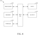
- FIG. 8 shows an example of a hardware configuration for a controller 800 that may be used to implement portions of the head-mounted display 100.
- the controller 800 includes a processor 802, a memory device 804, a storage device 806, one or more input devices 808, and one or more output devices 810. These components may be interconnected by hardware such as a bus 812 that allows communication between the components.
- the processor 802 may be a conventional device such as a central processing unit and is operable to execute computer program instructions and perform operations described by the computer program instructions.
- the memory device 804 may be a volatile, high-speed, short-term information storage device such as a random-access memory module.
- the storage device 806 may be a non-volatile information storage device such as a hard drive or a solid-state drive.
- the input devices 808 may include sensors and/or any type of human-machine interface, such as buttons, switches, a keyboard, a mouse, a touchscreen input device, a gestural input device, or an audio input device.
- the output devices 810 may include any type of device operable to provide an indication to a user regarding an operating state, such as a display screen, a light-control panel, or an audio output.
- a physical environment refers to a physical world that people can sense and/or interact with without aid of electronic systems.
- Physical environments such as a physical park, include physical articles, such as physical trees, physical buildings, and physical people. People can directly sense and/or interact with the physical environment, such as through sight, touch, hearing, taste, and smell.
- a computer-generated reality (CGR) environment refers to a wholly or partially simulated environment that people sense and/or interact with via an electronic system.
- CGR computer-generated reality
- a subset of a person's physical motions, or representations thereof, are tracked, and, in response, one or more characteristics of one or more virtual objects simulated in the CGR environment are adjusted in a manner that comports with at least one law of physics.
- a CGR system may detect a person's head turning and, in response, adjust graphical content and an acoustic field presented to the person in a manner similar to how such views and sounds would change in a physical environment.
- adjustments to characteristic(s) of virtual object(s) in a CGR environment may be made in response to representations of physical motions (e.g., vocal commands).
- a person may sense and/or interact with a CGR object using any one of their senses, including sight, sound, touch, taste, and smell.
- a person may sense and/or interact with audio objects that create 3D or spatial audio environment that provides the perception of point audio sources in 3D space.
- audio objects may enable audio transparency, which selectively incorporates ambient sounds from the physical environment with or without computer-generated audio.
- a person may sense and/or interact only with audio objects.
- Examples of CGR include virtual reality and mixed reality.
- a virtual reality (VR) environment refers to a simulated environment that is designed to be based entirely on computer-generated sensory inputs for one or more senses.
- a VR environment comprises a plurality of virtual objects with which a person may sense and/or interact. For example, computer-generated imagery of trees, buildings, and avatars representing people are examples of virtual objects.
- a person may sense and/or interact with virtual objects in the VR environment through a simulation of the person's presence within the computer-generated environment, and/or through a simulation of a subset of the person's physical movements within the computer-generated environment.
- a mixed reality (MR) environment refers to a simulated environment that is designed to incorporate sensory inputs from the physical environment, or a representation thereof, in addition to including computer-generated sensory inputs (e.g., virtual objects).
- MR mixed reality
- a mixed reality environment is anywhere between, but not including, a wholly physical environment at one end and virtual reality environment at the other end.
- computer-generated sensory inputs may respond to changes in sensory inputs from the physical environment.
- some electronic systems for presenting an MR environment may track location and/or orientation with respect to the physical environment to enable virtual objects to interact with real objects (that is, physical articles from the physical environment or representations thereof). For example, a system may account for movements so that a virtual tree appears stationery with respect to the physical ground.
- Examples of mixed realities include augmented reality and augmented virtuality.
- An augmented reality (AR) environment refers to a simulated environment in which one or more virtual objects are superimposed over a physical environment, or a representation thereof.
- an electronic system for presenting an AR environment may have a transparent or translucent display through which a person may directly view the physical environment.
- the system may be configured to present virtual objects on the transparent or translucent display, so that a person, using the system, perceives the virtual objects superimposed over the physical environment.
- a system may have an opaque display and one or more imaging sensors that capture images or video of the physical environment, which are representations of the physical environment. The system composites the images or video with virtual objects and presents the composition on the opaque display.
- a person, using the system indirectly views the physical environment by way of the images or video of the physical environment, and perceives the virtual objects superimposed over the physical environment.
- a video of the physical environment shown on an opaque display is called "pass-through video,” meaning a system uses one or more image sensor(s) to capture images of the physical environment and uses those images in presenting the AR environment on the opaque display.
- a system may have a projection system that projects virtual objects into the physical environment, for example, as a hologram or on a physical surface, so that a person, using the system, perceives the virtual objects superimposed over the physical environment.
- An augmented reality environment also refers to a simulated environment in which a representation of a physical environment is transformed by computer-generated sensory information.
- a system may transform one or more sensor images to impose a select perspective (e.g., viewpoint) different than the perspective captured by the imaging sensors.
- a representation of a physical environment may be transformed by graphically modifying (e.g., enlarging) portions thereof, such that the modified portion may be representative but not photorealistic versions of the originally captured images.
- a representation of a physical environment may be transformed by graphically eliminating or obfuscating portions thereof.
- An augmented virtuality (AV) environment refers to a simulated environment in which a virtual or computer-generated environment incorporates one or more sensory inputs from the physical environment.
- the sensory inputs may be representations of one or more characteristics of the physical environment.
- an AV park may have virtual trees and virtual buildings, but people with faces photorealistically reproduced from images taken of physical people.
- a virtual object may adopt a shape or color of a physical article imaged by one or more imaging sensors.
- a virtual object may adopt shadows consistent with the position of the sun in the physical environment.
- a head-mounted system may have one or more speaker(s) and an integrated opaque display.
- a head-mounted system may be configured to accept an external opaque display (e.g., a smartphone).
- the head-mounted system may incorporate one or more imaging sensors to capture images or video of the physical environment, and/or one or more microphones to capture audio of the physical environment.
- a head-mounted system may have a transparent or translucent display.
- the transparent or translucent display may have a medium through which light representative of images is directed to a person's eyes.
- the display may utilize digital light projection, OLEDs, LEDs, uLEDs, liquid crystal on silicon, laser scanning light source, or any combination of these technologies.
- the medium may be an optical waveguide, a hologram medium, an optical combiner, an optical reflector, or any combination thereof.
- the transparent or translucent display may be configured to become opaque selectively.
- Projection-based systems may employ retinal projection technology that projects graphical images onto a person's retina. Projection systems also may be configured to project virtual objects into the physical environment, for example, as a hologram or on a physical surface.
- this gathered data may include personal information data that uniquely identifies or can be used to contact or locate a specific person.
- personal information data can include demographic data, location-based data, telephone numbers, email addresses, twitter ID's, home addresses, data or records relating to a user's health or level of fitness (e.g., vital signs measurements, medication information, exercise information), date of birth, or any other identifying or personal information.
- the present disclosure recognizes that the use of such personal information data, in the present technology, can be used to the benefit of users.
- the personal information data can be used to deliver targeted content that is of greater interest to the user.
- other uses for personal information data that benefit the user are also contemplated by the present disclosure.
- health and fitness data may be used to provide insights into a user's general wellness or may be used as positive feedback to individuals using technology to pursue wellness goals.
- the present disclosure contemplates that the entities responsible for the collection, analysis, disclosure, transfer, storage, or other use of such personal information data will comply with well-established privacy policies and/or privacy practices.
- such entities should implement and consistently use privacy policies and practices that are generally recognized as meeting or exceeding industry or governmental requirements for maintaining personal information data private and secure.
- Such policies should be easily accessible by users and should be updated as the collection and/or use of data changes.
- Personal information from users should be collected for legitimate and reasonable uses of the entity and not shared or sold outside of those legitimate uses. Further, such collection/sharing should occur after receiving the informed consent of the users.
- policies and practices should be adapted for the particular types of personal information data being collected and/or accessed and adapted to applicable laws and standards, including jurisdiction-specific considerations. For instance, in the US, collection of or access to certain health data may be governed by federal and/or state laws, such as the Health Insurance Portability and Accountability Act (HIPAA); whereas health data in other countries may be subject to other regulations and policies and should be handled accordingly. Hence different privacy practices should be maintained for different personal data types in each country.
- HIPAA Health Insurance Portability and Accountability Act
- the present disclosure also contemplates embodiments in which users selectively block the use of, or access to, personal information data. That is, the present disclosure contemplates that hardware and/or software elements can be provided to prevent or block access to such personal information data.
- the present technology can be configured to allow users to select to "opt in” or “opt out” of participation in the collection of personal information data during registration for services or anytime thereafter.
- the present disclosure contemplates providing notifications relating to the access or use of personal information. For instance, a user may be notified upon downloading an app that their personal information data will be accessed and then reminded again just before personal information data is accessed by the app.
- personal information data should be managed and handled in a way to minimize risks of unintentional or unauthorized access or use. Risk can be minimized by limiting the collection of data and deleting data once it is no longer needed.
- data de-identification can be used to protect a user's privacy. De-identification may be facilitated, when appropriate, by removing specific identifiers (e.g., date of birth, etc.), controlling the amount or specificity of data stored (e.g., collecting location data a city level rather than at an address level), controlling how data is stored (e.g., aggregating data across users), and/or other methods.
- the present disclosure broadly covers use of personal information data to implement one or more various disclosed embodiments
- the present disclosure also contemplates that the various embodiments can also be implemented without the need for accessing such personal information data. That is, the various embodiments of the present technology are not rendered inoperable due to the lack of all or a portion of such personal information data.
- content can be displayed to users by inferring preferences based on non-personal information data or a bare minimum amount of personal information, such as the content being requested by the device associated with a user, other non-personal information available to the device, or publicly available information.
Landscapes
- Physics & Mathematics (AREA)
- General Physics & Mathematics (AREA)
- Optics & Photonics (AREA)
- Devices For Indicating Variable Information By Combining Individual Elements (AREA)
- Instrument Panels (AREA)
Description
- This disclosure relates to a display system and, in particular, a head-mounted display and an adjustment mechanism therefor.
- Head-mounted displays (HMD) are electronic devices that display graphics to a user wearing the head-mounted display, for example, when participating in activities related to computer-generated, augmented, virtual, and/or mixed realities. The head-mounted display may be worn by users having differing head sizes and facial features, so the ability to adjust a fit of the head-mounted display for a particular user having specific features is a high priority. Existing head-mounted displays can be adjusted for circumferential fit using features such headbands made from elastic materials and temple-located adjustment mechanisms that change a length of a non-elastic headband between a variety of predetermined lengths. However, these adjustment options do not address differences in facial features, such as different inter-pupillary distances (IPD) among users.
-
US 2015103306 is directed to a VR headset with an adjustment mechanism coupled to eyepieces of the headset and operable to simultaneously move the eyepieces. It describes a knob-based adjustment mechanism with a linear actuator 560 and bar linkages 562a,b. The adjustment mechanism allows a user to manipulate the interpupillary distance by moving the eyepieces inwardly or outwardly relative to the adjustment mechanism. The user rotates the knob-based adjustment mechanism in a clockwise direction which causes a linear extension of the linear actuator device shaft. -
US 2001055947 is directed to a damper assembly in which the position of the damper blades is controlled by an electric powered actuator. The powered actuator rotates a threaded lead screw shaft attached to an operator means attached to the damper blades of the damper. It describes a spring means 35 that acts on the damper doors, such as of a vent. There is a solenoid and piston that translates to make contact with a nut 66 that is then turned about a screw 68. - Disclosed herein are implementations of a head-mounted display and adjustment mechanisms for optical components within the head-mounted display. The invention is defined by the claims.
- In a first aspect, a head-mounted display includes an optical assembly and an actuator. The actuator includes a movement mechanism configured to adjust a position of an optical component within the optical assembly, a locking-release mechanism configured to modify operation of the movement mechanism upon detection of a dynamic event, and a dampening mechanism configured to control positional changes of the optical component during the dynamic event.
- In the first aspect, the movement mechanism can be configured to adjust the position of the optical component within the optical assembly to a pre-dynamic event position in accordance with detection of an end of the dynamic event. The movement mechanism can comprise a lead screw and a nut assembly, the nut assembly configured to translate along the lead screw based on rotation of the lead screw. The nut assembly can comprise separable first and second portions, and the locking-release mechanism can include a spring that linearly biases one of the first and second portions of the nut assembly against the lead screw. The modified operation of the movement mechanism can include one of the first and second portions of the nut assembly being disengaged from the lead screw. The dampening mechanism can comprise an electromagnetic component configured to generate attraction between the nut assembly and the lead screw during the dynamic event. The movement mechanism can comprise a lead screw and a plate configured to translate along the lead screw based on rotation of the lead screw. The locking-release mechanism can include a spring that torsionally biases the plate against the lead screw. Modified operation of the movement mechanism can include the plate being disengaged from the lead screw. The dampening mechanism can comprise an electromagnetic component configured to generate attraction between the plate and the lead screw during the dynamic event. The dampening mechanism can comprise an electromagnetic component configured to repel the movement mechanism from end portions of the actuator during the dynamic event. The dampening mechanism can comprise a spring or cable configured to restrict motion of the movement mechanism during the dynamic event. The first aspect may include any combination of the features described in this paragraph.
- In a second aspect, a method includes detecting, using a sensor in a head-mounted display, a start of a dynamic event. I accordance with detection of the start of the dynamic event and using a locking-release mechanism, the method includes modifying operation of a movement mechanism. The movement mechanism is configured to adjust a position of an optical component within an optical assembly of the head-mounted display. The method includes detecting, using the sensor in the head-mounted display, an end of the dynamic event. In accordance with detection of the end of the dynamic event and using the movement mechanism, the method includes adjusting the position of the optical component within the optical assembly to a pre-dynamic event position.
- In the second aspect, and in accordance with detection of the start of the dynamic event and using a dampening mechanism, the method can include controlling positional changes of the movement mechanism during the dynamic event. The dampening mechanism can comprise an electromagnetic component configured to repel components within the movement mechanism during the dynamic event. The dampening mechanism can comprise an electromagnetic component configured to cause attraction between components within the movement mechanism during the dynamic event. The dampening mechanism can comprise a spring or cable configured to restrict motion of the movement mechanism during the dynamic event. The movement mechanism can comprise a lead screw and a nut assembly nut assembly configured to translate along the lead screw based on rotation of the lead screw. The nut assembly can comprise separable first and second portions. The locking-release mechanism can include a spring that linearly biases one of the first and second portions of the nut assembly against the lead screw. Modified operation of the movement mechanism can include one of the first and second portions of the nut assembly being disengaged from the lead screw. The movement mechanism can comprise a lead screw and a plate configured to translate along the lead screw based on rotation of the lead screw. The locking-release mechanism can include a spring that torsionally biases the plate against the lead screw. Modified operation of the movement mechanism can include the plate being disengaged from the lead screw. The second aspect may include any combination of the features described in this paragraph.
- In a third aspect, an actuator includes a movement mechanism configured to adjust a position of an optical component within an optical assembly of a head-mounted display. The movement mechanism includes a lead screw and a threaded component. The threaded component is configured to translate along the lead screw based on rotation of the lead screw. The actuator also includes a locking-release mechanism configured to modify operation of the movement mechanism upon detection of a dynamic event. The locking-release mechanism includes a spring configured to bias the threaded component against the lead screw. Modified operation of the movement mechanism includes the threaded component being disengaged from the lead screw. The actuator also includes a dampening mechanism configured to control positional changes of the movement mechanism during the dynamic event.
- In the third aspect, the dampening mechanism can comprise an electromagnetic component configured to generate attraction between the threaded component and the lead screw during the dynamic event. The dampening mechanism can comprise an electromagnetic component configured to repel the movement mechanism from end portions of the actuator during the dynamic event. The third aspect may include any combination of the features described in this paragraph.
- The disclosure is best understood from the following detailed description when read in conjunction with the accompanying drawings. It is emphasized that, according to common practice, the various features of the drawings are not to-scale. On the contrary, the dimensions of the various features are arbitrarily expanded or reduced for clarity.
-
FIG. 1 is a top view of a head-mounted display. -
FIG. 2A is a detail view of an actuator disposed within a head-mounted display similar to the head-mounted display ofFIG. 1 . -
FIG. 2B is a partially-exploded sectional view of the actuator ofFIG. 2A . -
FIG. 3A is a detail view of another actuator disposed within a head-mounted display similar to the head-mounted display ofFIG. 1 . -
FIG. 3B is a partially-exploded sectional view of the actuator ofFIG. 3A . -
FIG. 4A is a detail view of another actuator disposed within a head-mounted display similar to the head-mounted display ofFIG. 1 . -
FIG. 4B is a partially-exploded sectional view of the actuator ofFIG. 4A . -
FIG. 5A is a detail view of an electromagnetic dampening mechanism for an actuator similar to the actuators ofFIGS. 2A, 2B ,3A, 3B ,4A, and 4B . -
FIG. 5B is a detail view of another electromagnetic dampening mechanism for an actuator similar to the actuator ofFIGS. 2A, 2B ,3A, 3B ,4A, and 4B . -
FIG. 6A is a detail view of a mechanical dampening mechanism for an actuator similar to the actuator ofFIGS. 2A, 2B ,3A, 3B ,4A, and 4B . -
FIG. 6B is a detail view of another mechanical dampening mechanism for an actuator similar to the actuator ofFIGS. 2A, 2B ,3A, 3B ,4A, and 4B . -
FIG. 7 is a flowchart depicting a process of operation for an actuator disposed within a head-mounted display similar to the head-mounted display ofFIG. 1 . -
FIG. 8 is a schematic hardware configuration for a controller in the head-mounted display ofFIG. 1 . - For improved performance, head-mounted displays require the alignment of optical components such as lenses, projection units, displays, screens, etc. to unique facial features among a variety of users in order to promote comfort, fit, performance, etc. During the alignment process, optical components can be physically repositioned in respect to other components within a head-mounted display. As packaging space is constrained within head-mounted displays, physical repositioning mechanisms should be small in size with tightly controlled motion, for example, small electro-mechanical actuators. Though small in size, the actuators should be able to withstand dynamic events and properly function after experiencing these dynamic events. Dynamic events can include shaking, jostling, dropping, impacting, or otherwise handling the head-mounted display in a manner that leads to forces being exerted upon optical components or subcomponents within the electro-mechanical actuators.
- In an example where an actuator used to reposition optical components employs a lead screw, locking-release mechanisms that allow disengagement or slip along the lead screw can be used in conjunction with dampening mechanisms that allow controlled sliding and/or stopping along a guide rail to prevent damage both to the actuator and to the optical components that undergo motion through use of the actuator. The locking-release and dampening mechanisms can include motor-driven, lead-screw system designs that leverage linear spring-loaded nut assemblies, torsional spring-loaded plates, drop-detection-based lock engagement or disengagement, and optical-component motion dampening during dynamic events. Detailed descriptions of these and other applicable mechanisms that improve performance of physical repositioning within a head-mounted display are described herein.
-
FIG. 1 is a top view of a head-mounteddisplay 100 that includes adisplay assembly 102 and ahead support 104. Thedisplay assembly 102 can include ahousing 106 and various sub-assemblies and electronics therein, such as one or moreoptical assemblies power electronics 114, andactuators 116. Various portions or subcomponents of theoptical assemblies 108, 110 (e.g., such as lenses, projection units, screens, or displays) can be repositionable using the one ormore actuators 116, details of which are described further herein. Theoptical assemblies sensors 112,power electronics 114, andactuators 116 are depicted schematically and in dashed lines to illustrate being hidden from view and disposed within thedisplay assembly 102. - The
head support 104 is coupled to left and right sides of the display assembly 102 (e.g., to the housing 106), extending rearward of thedisplay assembly 102 and between the left and right sides thereof. When the head-mounteddisplay 100 is worn on a head of a user, thedisplay assembly 102 extends across a front of the head of the user (i.e., the face of the user), while thehead support 104 extends rearward along left and right sides of the head of the user and across a rear of the head of the user. Thus, thedisplay assembly 102 and thehead support 104 cooperatively extend around the head of the user. Thehead support 104 includes aband 118 and one or more circumferential adjustment mechanisms 120 (e.g., two as shown on the left and right sides) - The
band 118 forms a primary portion of thehead support 104, which engages the head of the user to support the head-mounteddisplay 100 worn on the head of the user. Each of thecircumferential adjustment mechanisms 120 removably couples thehead support 104 to thedisplay assembly 102 and allows thehead support 104 to change length overall by changing the length between theband 118 and thecircumferential adjustment mechanisms 120. Though twocircumferential adjustment mechanisms 120 are shown as acting from opposing sides of thehead support 104, thehead support 104 may alternatively employ a single adjustment mechanism. - The
band 118 can be elastic, flexible, or otherwise deformable to accommodate different shapes of heads of the users. Theband 118 can be formed of or otherwise include an elastic or silicone material. Theband 118 may also be configured to transfer electrical power from a power source (e.g., an external battery) to thedisplay assembly 102. For example, theband 118 may include aflexible circuit 122 extending from apower connector 124, through thecircumferential adjustment mechanism 120, to a corresponding power connector (not shown) of thedisplay assembly 102. The flexible circuit 122 (hidden and illustrated in dash-dot lines) may be embedded in the elastic or silicone material of theband 118 or otherwise hidden from view by the material of theband 118. In this manner, theband 118 may supply electrical current to thedisplay assembly 102 inclusive of theoptical assemblies sensors 112,power electronics 114, andactuators 116. -
FIGS. 2A and 2B are detail and partially-exploded sectional views of anactuator 200. The partially-exploded sectional view ofFIG. 2B is representative of the location indicated inFIG. 2A . Theactuator 200 may serve as theactuator 116 disposed in the head-mounteddisplay 100 ofFIG. 1 . - The
actuator 200 includes a movement mechanism formed by amotor 202, alead screw 204, aguide rail 206, and anut assembly 208. Thenut assembly 208 is configured to translate along thelead screw 204 based on rotation of thelead screw 204 and thread engagement between thenut assembly 208 and thelead screw 204. For example, thelead screw 204 can be rotationally driven by themotor 202 to cause translation of thenut assembly 208. In this manner, the movement mechanism is configured to adjust a position of an optical component (e.g., a lens, a display, a projector, a screen, a lens and a display, etc., not shown) within an optical assembly (e.g., within theoptical assemblies lead screw 204, the threads on thenut assembly 208, or both, can be coated to provide a longer life for theactuator 200 and to reduce friction and noise associated with operation of theactuator 200. - Positional adjustment of optical component(s) can be achieved using the described movement mechanism, for example, by coupling the optical component(s) that require(s) repositioning to a portion of the
nut assembly 208, though the coupling is not shown. The movement mechanism can be used to modify optical component spacing along a focal axis or modify interpupillary distance, for example, between optical assemblies within the same head-mounted display. Thenut assembly 208 can be designed to avoid unintended rotation, for example, by use of theguide rail 206 extending parallel to thelead screw 204, though other anti-rotation features in theactuator 200 are also possible. When theguide rail 206 is used as shown inFIGS. 2A and 2B , thenut assembly 208 translates along both thelead screw 204 and theguide rail 206 based on rotation of thelead screw 204 as driven by themotor 202. - The
actuator 200 also includes a locking-release mechanism formed by separable halves orportions nut assembly 208 and one ormore springs 214 that can linearly bias theportion 212 against thelead screw 204, against theguide rail 206, and against theportion 210 of thenut assembly 208 as is best seen in the partially-exploded sectional view ofFIG. 2B . In this example, thenut assembly 208 has a split-nut configuration with theportion 212 of thenut assembly 208 configured to translate away from theportion 210 of thenut assembly 208 when a load experienced is sufficient to overcome a load generated by thesprings 214 against theportion 212 of thenut assembly 208. Sufficient loads of this type can occur during dynamic events (e.g., shaking, jostling, dropping, or impacting a head-mounted display that includes the actuator 200). - During a dynamic event that generates sufficient force, the threads on the
lead screw 204 and the threads on theportions nut assembly 208 becomes free to slide along thelead screw 204 and theguide rail 206, thus limiting or avoiding damage to thenut assembly 208 and/or to thelead screw 204 during the dynamic event based on operation of the described locking-release mechanism. After a dynamic event, when sufficient loads are no longer experienced by theactuator 200, the threads on thelead screw 204 and the threads on theportions nut assembly 208 can become reengaged, and thenut assembly 208 can once again be driven along thelead screw 204 by the motor. - Upon reengagement, the
nut assembly 208 may be in a different position along thelead screw 204 than prior to or during the dynamic event. In this case, the movement mechanism may be configured to adjust the position of thenut assembly 208, and in turn, any optical components coupled or otherwise connected to thenut assembly 208, to a pre-dynamic event position, that is, to a position that was documented for thenut assembly 208 in respect to thelead screw 204 prior to the dynamic event. Though bothportions nut assembly 208 are shown as being threaded at the interface to thelead screw 204, in some examples, only theportion 212 may include threads without impacting operation of theactuator 200. - To effectively implement the locking-release mechanism of the
actuator 200, a position sensor (not shown) can be used to determine a position of thenut assembly 208 in respect to thelead screw 204 before, during, and after a dynamic event. An accelerometer, inertial measurement unit, or any other sensor (not shown) can be used to determine a beginning, duration, and end of the dynamic event. In another example, a magnetic encoder system can include a sensor that determines a landing position of theportions nut assembly 208 in respect to the lead screw 204 (or other portion of the actuator 200), and a controller can perform a recalibration, repositioning theportions nut assembly 208 to pre-dynamic event positions along thelead screw 204 after the dynamic event. -
FIGS. 3A and 3B are detail and partially-exploded sectional views of anotheractuator 300. The partially-exploded sectional view ofFIG. 3B is representative of the location indicated inFIG. 3A . Theactuator 300 may serve as theactuator 116 disposed in the head-mounteddisplay 100 ofFIG. 1 and may be similar to theactuator 200 described in respect toFIGS. 2A and 2B . Differences between the actuator 300 and theactuator 200 are highlighted herein. - The
actuator 300 includes a movement mechanism formed by amotor 302, alead screw 304, aguide rail 306, and anut assembly 308. Thenut assembly 308 is configured to translate along thelead screw 304 and theguide rail 306 based on rotation of thelead screw 304 and thread engagement between thenut assembly 308 and thelead screw 304. Thenut assembly 308 can be designed to avoid unintended rotation, for example, by use of theguide rail 306 extending parallel to thelead screw 304, though other anti-rotation features in theactuator 300 are also possible. - The
actuator 300 also includes a locking-release mechanism formed byseparable portions nut assembly 308 and one ormore springs 314 that can linearly bias theportion 312 against theguide rail 306 and thecentral-most portion 311 of thenut assembly 308. In turn, theportion 311 can be linearly biased against thelead screw 304 and theportion 310 of thenut assembly 308 as is best seen in the partially-exploded sectional view ofFIG. 3B . In this example, thenut assembly 308 has threeportions portions nut assembly 308 configured to translate away and become disengaged from theportion 310 of thenut assembly 308 when a load experienced is sufficient to overcome a load generated by thesprings 314 against theportion 312 of thenut assembly 308. Sufficient loads of this type can occur during dynamic events (e.g., shaking, jostling, dropping, or impacting a head-mounted display that includes the actuator 300). - The
actuator 300 ofFIGS. 3A and 3B differs from theactuator 200 ofFIGS. 2A and 2B in that thenut assembly 308 is used in place of thenut assembly 208. Theactuator 300 ofFIGS. 3A and 3B may be useful in vertically tight packaging spaces, that is, theactuator 300 may be shorter in height than theactuator 200 due to the construction of thenut assemblies actuator 200 ofFIGS. 2A and 2B may be useful in horizontally tight packaging spaces, that is, theactuator 200 may be narrower in width than theactuator 300 due to the construction of thenut assemblies -
FIGS. 4A and 4B are detail and partially-exploded sectional views of anotheractuator 400. The partially-exploded sectional view ofFIG. 4B is representative of the location indicated inFIG. 4A . Theactuator 400 may serve as theactuator 116 disposed in the head-mounteddisplay 100 ofFIG. 1 and may be similar to theactuators FIGS. 2A, 2B ,3A, and 3B . Differences between the actuator 400 and theactuators - The
actuator 400 includes a movement mechanism formed by amotor 402, alead screw 404, aguide rail 406, and atorsion assembly 408. Thetorsion assembly 408 is configured to translate along thelead screw 404 and theguide rail 406 based on rotation of thelead screw 404 and thread engagement between thetorsion assembly 408 and thelead screw 404. Thetorsion assembly 408 can be designed to avoid unintended rotation, for example, by use of theguide rail 406 extending through thetorsion assembly 408, though other anti-rotation features in theactuator 400 are also possible. - The
torsion assembly 408 includes aplate 410, asupport 412, and atorsional spring 414 that can torsionally bias theplate 410 against thelead screw 404 to form a locking-release mechanism of theactuator 400. In this example, thetorsional spring 414 acts against both theplate 410 and thesupport 412 such that theplate 410 is configured to rotate away and become disengaged from thelead screw 404 when a load experienced is sufficient to overcome a load generated by thespring 414 against theplate 410 and thesupport 412. Sufficient loads of this type can occur during dynamic events (e.g., shaking, jostling, dropping, or impacting a head-mounted display that includes the actuator 400). - The
actuator 400 ofFIGS. 4A and 4B differs from theactuators FIGS. 2A, 2B ,3A, and 3B in that thetorsion assembly 408 with therotatable plate 410 is used in place of thenut assemblies actuator 400 ofFIGS. 4A and 4B can support unique positional relationships between thelead screw 404 and theguide rail 406 since these components can be both vertically and horizontally offset while remaining generally parallel. Further, there is less physical engagement between theplate 410 and thelead screw 404 than is present between thenut assemblies - The
actuators FIGS. 2A, 2B ,3A, 3B ,4A, and 4B include split-nut and torsional-type movement mechanisms usinglead screws - A consequence of using the locking-release mechanisms described in respect to
FIGS. 2A, 2B ,3A, 3B ,4A, and 4B is that thenut assemblies torsion assembly 408 can become generally free-sliding along theguide rails nut assemblies torsion assembly 408 from the lead screws 204, 304, 404. To avoid damage to optical components having motion controlled by theactuators -
FIGS. 5A and 5B are detail views of magnetic dampening mechanisms for anactuator 500 similar to theactuators FIGS. 2A, 2B ,3A, 3B ,4A, and 4B . Theactuator 500 may serve as theactuator 116 disposed in the head-mounteddisplay 100 ofFIG. 1 . Theactuator 500 includes a movement mechanism formed by amotor 502, alead screw 504, aguide rail 506, and anut assembly 508. Thenut assembly 508 is configured to translate along thelead screw 504 and theguide rail 506 based on rotation of thelead screw 504 and thread engagement between thenut assembly 508 and thelead screw 504. - Locking-release mechanisms similar to those described in reference to
FIGS. 2A, 2B ,3A, and 3B , can cause thenut assembly 508 to become disengaged from thelead screw 504, for example, during a dynamic event. To minimize free sliding of thenut assembly 508, theactuator 500 can include an electromagnetic dampening mechanism formed by anelectromagnetic component 516 disposed within or forming a portion of thenut assembly 508 as shown in dotted line inFIGS. 5A and 5B . - Referring to
FIG. 5A , the electromagnetic dampening mechanism can includeelectromagnetic components guide rail 506 as shown in dotted line for hidden representation. In this embodiment, theelectromagnetic components electromagnetic component 516 during a dynamic event, thus serving as cushions or bumpers to slow or prohibit thenut assembly 508 from impacting the ends of theguide rail 506 when sliding. In other embodiments, thenut assembly 508 may include portions formed of ferritic or other material susceptible to magnetic repulsion, and thenut assembly 508 may be repelled by theelectromagnetic components - Referring to
FIG. 5B , the electromagnetic dampening mechanism can includeelectromagnetic component 522 that runs the length of theguide rail 506 as shown in dotted line. In this embodiment, theelectromagnetic component 522 can be controlled to actuate and attract theelectromagnetic component 516 during a dynamic event, thus serving to slow motion of thenut assembly 508 during the dynamic event due to attraction between theelectromagnetic components guide rail 506 may be formed of ferritic or other material susceptible to magnetic attraction, and theelectromagnetic component 516 may be attracted to theguide rail 506 during dynamic events. - Other magnetic dampening mechanisms are also possible. For example, the
electromagnetic components electromagnetic components -
FIG. 6A and 6B are detail views of mechanical dampening mechanisms for anactuator 600 similar to theactuators FIGS. 2A, 2B ,3A, 3B ,5A, and 5B . Theactuator 600 may serve as theactuator 116 disposed in the head-mounteddisplay 100 ofFIG. 1 . Theactuator 600 includes a movement mechanism formed by amotor 602, alead screw 604, aguide rail 606, and anut assembly 608. Thenut assembly 608 is configured to translate along thelead screw 604 and theguide rail 606 based on rotation of thelead screw 604 and thread engagement between thenut assembly 608 and thelead screw 604. - Locking-release mechanisms similar to those described in reference to
FIGS. 2A, 2B ,3A, and 3B can cause thenut assembly 608 to become disengaged from thelead screw 604, for example, during a dynamic event. To minimize free sliding of thenut assembly 608, theactuator 600 can include a mechanical dampening mechanism such as those described in reference toFIGS. 6A and 6B . - Referring to
FIG. 6A , the mechanical dampening mechanism can include one ormore cables 626, 628 (two are shown in solid and dotted line) disposed proximate to ends of thelead screw 604 and theguide rail 606. In this embodiment, thecables nut assembly 608 to avoid having thenut assembly 608 impact the ends of thelead screw 604 andguide rail 606 when sliding. For example, thecables cables nut assembly 608. - Referring to
FIG. 6B , the mechanical dampening mechanism can include one ormore springs 630, 632 (two are shown) disposed proximate to ends of thelead screw 604 and theguide rail 606. In this embodiment, thesprings nut assembly 608 to avoid having thenut assembly 608 impact the ends of thelead screw 604 andguide rail 606 when sliding. In another example, thesprings -
FIG. 7 is a flowchart depicting aprocess 700 of operation for an actuator similar to theactuators FIGS. 2A, 2B ,3A, 3B ,4A, 4B ,5A, 5B ,6A, and 6B disposed within a head-mounted display similar to the head-mounteddisplay 100 ofFIG. 1 . - At 710, the
process 700 includes detecting a start of a dynamic event, for example, using a sensor such as a position sensor, an accelerometer, an inertial measurement unit, or other sensor within or associated with the head-mounted display. The dynamic event can include events such as shaking, jostling, dropping, impacting, or otherwise handling the head-mounted display in a manner that leads to forces above a disengagement threshold being exerted upon components of the actuator and optical components of an optical assembly. - At 720, the
process 700 includes activating a locking-release mechanism such as the locking-release mechanisms described in reference to theactuators nut assemblies 208, 308) or the torsion assembly (e.g., the torsion assembly 408) from the lead screw (e.g., the lead screws 204, 304, 404). - At 730, shown in dotted line to represent its optional nature, the
process 700 includes activating a dampening mechanism such as the dampening mechanisms described in reference to theactuators - At 740, the
process 700 includes detecting an end of the dynamic event, for example, using a sensor such as a position sensor, an accelerometer, an inertial measurement unit, or other sensor within or associated with the head-mounted display. The end of the dynamic event can also be detected based on detecting arrested motion of components within a movement mechanism that were previously in motion during the dynamic event. - At 750, shown in dotted line to represent its optional nature, the
process 700 includes adjusting a position of an optical component within an optical assembly to a pre-dynamic event position. The movement mechanism can be used to move, for example, a nut assembly or a torsion assembly within an actuator from its current post-dynamic event position to the pre-dynamic event position. Movement of the optical component is tied to movement of the movement mechanism in this example. Repositioning supports improved function of the overall head-mounted display as the user will not be required to readjust optical components within optical assemblies after a dynamic event. -
FIG. 8 shows an example of a hardware configuration for acontroller 800 that may be used to implement portions of the head-mounteddisplay 100. In the illustrated example, thecontroller 800 includes aprocessor 802, amemory device 804, astorage device 806, one ormore input devices 808, and one ormore output devices 810. These components may be interconnected by hardware such as abus 812 that allows communication between the components. - The
processor 802 may be a conventional device such as a central processing unit and is operable to execute computer program instructions and perform operations described by the computer program instructions. Thememory device 804 may be a volatile, high-speed, short-term information storage device such as a random-access memory module. Thestorage device 806 may be a non-volatile information storage device such as a hard drive or a solid-state drive. Theinput devices 808 may include sensors and/or any type of human-machine interface, such as buttons, switches, a keyboard, a mouse, a touchscreen input device, a gestural input device, or an audio input device. Theoutput devices 810 may include any type of device operable to provide an indication to a user regarding an operating state, such as a display screen, a light-control panel, or an audio output. - In general, a physical environment refers to a physical world that people can sense and/or interact with without aid of electronic systems. Physical environments, such as a physical park, include physical articles, such as physical trees, physical buildings, and physical people. People can directly sense and/or interact with the physical environment, such as through sight, touch, hearing, taste, and smell.
- In contrast, a computer-generated reality (CGR) environment refers to a wholly or partially simulated environment that people sense and/or interact with via an electronic system. In CGR, a subset of a person's physical motions, or representations thereof, are tracked, and, in response, one or more characteristics of one or more virtual objects simulated in the CGR environment are adjusted in a manner that comports with at least one law of physics. For example, a CGR system may detect a person's head turning and, in response, adjust graphical content and an acoustic field presented to the person in a manner similar to how such views and sounds would change in a physical environment. In some situations (e.g., for accessibility reasons), adjustments to characteristic(s) of virtual object(s) in a CGR environment may be made in response to representations of physical motions (e.g., vocal commands).
- A person may sense and/or interact with a CGR object using any one of their senses, including sight, sound, touch, taste, and smell. For example, a person may sense and/or interact with audio objects that create 3D or spatial audio environment that provides the perception of point audio sources in 3D space. In another example, audio objects may enable audio transparency, which selectively incorporates ambient sounds from the physical environment with or without computer-generated audio. In some CGR environments, a person may sense and/or interact only with audio objects.
- Examples of CGR include virtual reality and mixed reality.
- A virtual reality (VR) environment refers to a simulated environment that is designed to be based entirely on computer-generated sensory inputs for one or more senses. A VR environment comprises a plurality of virtual objects with which a person may sense and/or interact. For example, computer-generated imagery of trees, buildings, and avatars representing people are examples of virtual objects. A person may sense and/or interact with virtual objects in the VR environment through a simulation of the person's presence within the computer-generated environment, and/or through a simulation of a subset of the person's physical movements within the computer-generated environment.
- In contrast to a VR environment, which is designed to be based entirely on computer-generated sensory inputs, a mixed reality (MR) environment refers to a simulated environment that is designed to incorporate sensory inputs from the physical environment, or a representation thereof, in addition to including computer-generated sensory inputs (e.g., virtual objects). On a virtuality continuum, a mixed reality environment is anywhere between, but not including, a wholly physical environment at one end and virtual reality environment at the other end.
- In some MR environments, computer-generated sensory inputs may respond to changes in sensory inputs from the physical environment. Also, some electronic systems for presenting an MR environment may track location and/or orientation with respect to the physical environment to enable virtual objects to interact with real objects (that is, physical articles from the physical environment or representations thereof). For example, a system may account for movements so that a virtual tree appears stationery with respect to the physical ground.
- Examples of mixed realities include augmented reality and augmented virtuality.
- An augmented reality (AR) environment refers to a simulated environment in which one or more virtual objects are superimposed over a physical environment, or a representation thereof. For example, an electronic system for presenting an AR environment may have a transparent or translucent display through which a person may directly view the physical environment. The system may be configured to present virtual objects on the transparent or translucent display, so that a person, using the system, perceives the virtual objects superimposed over the physical environment. Alternatively, a system may have an opaque display and one or more imaging sensors that capture images or video of the physical environment, which are representations of the physical environment. The system composites the images or video with virtual objects and presents the composition on the opaque display. A person, using the system, indirectly views the physical environment by way of the images or video of the physical environment, and perceives the virtual objects superimposed over the physical environment. As used herein, a video of the physical environment shown on an opaque display is called "pass-through video," meaning a system uses one or more image sensor(s) to capture images of the physical environment and uses those images in presenting the AR environment on the opaque display. Further alternatively, a system may have a projection system that projects virtual objects into the physical environment, for example, as a hologram or on a physical surface, so that a person, using the system, perceives the virtual objects superimposed over the physical environment.
- An augmented reality environment also refers to a simulated environment in which a representation of a physical environment is transformed by computer-generated sensory information. For example, in providing pass-through video, a system may transform one or more sensor images to impose a select perspective (e.g., viewpoint) different than the perspective captured by the imaging sensors. As another example, a representation of a physical environment may be transformed by graphically modifying (e.g., enlarging) portions thereof, such that the modified portion may be representative but not photorealistic versions of the originally captured images. As a further example, a representation of a physical environment may be transformed by graphically eliminating or obfuscating portions thereof.
- An augmented virtuality (AV) environment refers to a simulated environment in which a virtual or computer-generated environment incorporates one or more sensory inputs from the physical environment. The sensory inputs may be representations of one or more characteristics of the physical environment. For example, an AV park may have virtual trees and virtual buildings, but people with faces photorealistically reproduced from images taken of physical people. As another example, a virtual object may adopt a shape or color of a physical article imaged by one or more imaging sensors. As a further example, a virtual object may adopt shadows consistent with the position of the sun in the physical environment.
- There are many different types of electronic systems that enable a person to sense and/or interact with various CGR environments. Examples include head-mounted systems, projection-based systems, heads-up displays (HUDs), vehicle windshields having integrated display capability, windows having integrated display capability, displays formed as lenses designed to be placed on a person's eyes (e.g., similar to contact lenses), headphones/earphones, speaker arrays, input systems (e.g., wearable or handheld controllers with or without haptic feedback), smartphones, tablets, and desktop/laptop computers. A head-mounted system may have one or more speaker(s) and an integrated opaque display. Alternatively, a head-mounted system may be configured to accept an external opaque display (e.g., a smartphone).
- The head-mounted system may incorporate one or more imaging sensors to capture images or video of the physical environment, and/or one or more microphones to capture audio of the physical environment. Rather than an opaque display, a head-mounted system may have a transparent or translucent display. The transparent or translucent display may have a medium through which light representative of images is directed to a person's eyes. The display may utilize digital light projection, OLEDs, LEDs, uLEDs, liquid crystal on silicon, laser scanning light source, or any combination of these technologies. The medium may be an optical waveguide, a hologram medium, an optical combiner, an optical reflector, or any combination thereof. In one embodiment, the transparent or translucent display may be configured to become opaque selectively. Projection-based systems may employ retinal projection technology that projects graphical images onto a person's retina. Projection systems also may be configured to project virtual objects into the physical environment, for example, as a hologram or on a physical surface.
- As described above, one aspect of the present technology is the gathering and use of data available from various sources, such as from the
sensors 112 or user profiles, to improve the delivery to users of content associated with the head-mounteddisplay 100. The present disclosure contemplates that in some instances, this gathered data may include personal information data that uniquely identifies or can be used to contact or locate a specific person. Such personal information data can include demographic data, location-based data, telephone numbers, email addresses, twitter ID's, home addresses, data or records relating to a user's health or level of fitness (e.g., vital signs measurements, medication information, exercise information), date of birth, or any other identifying or personal information. - The present disclosure recognizes that the use of such personal information data, in the present technology, can be used to the benefit of users. For example, the personal information data can be used to deliver targeted content that is of greater interest to the user. Further, other uses for personal information data that benefit the user are also contemplated by the present disclosure. For instance, health and fitness data may be used to provide insights into a user's general wellness or may be used as positive feedback to individuals using technology to pursue wellness goals.
- The present disclosure contemplates that the entities responsible for the collection, analysis, disclosure, transfer, storage, or other use of such personal information data will comply with well-established privacy policies and/or privacy practices. In particular, such entities should implement and consistently use privacy policies and practices that are generally recognized as meeting or exceeding industry or governmental requirements for maintaining personal information data private and secure. Such policies should be easily accessible by users and should be updated as the collection and/or use of data changes. Personal information from users should be collected for legitimate and reasonable uses of the entity and not shared or sold outside of those legitimate uses. Further, such collection/sharing should occur after receiving the informed consent of the users.
- Additionally, such entities should consider taking any needed steps for safeguarding and securing access to such personal information data and ensuring that others with access to the personal information data adhere to their privacy policies and procedures. Further, such entities can subject themselves to evaluation by third parties to certify their adherence to widely accepted privacy policies and practices. In addition, policies and practices should be adapted for the particular types of personal information data being collected and/or accessed and adapted to applicable laws and standards, including jurisdiction-specific considerations. For instance, in the US, collection of or access to certain health data may be governed by federal and/or state laws, such as the Health Insurance Portability and Accountability Act (HIPAA); whereas health data in other countries may be subject to other regulations and policies and should be handled accordingly. Hence different privacy practices should be maintained for different personal data types in each country.
- Despite the foregoing, the present disclosure also contemplates embodiments in which users selectively block the use of, or access to, personal information data. That is, the present disclosure contemplates that hardware and/or software elements can be provided to prevent or block access to such personal information data. For example, in the case of user-profile-based delivery of content, the present technology can be configured to allow users to select to "opt in" or "opt out" of participation in the collection of personal information data during registration for services or anytime thereafter. In addition to providing "opt in" and "opt out" options, the present disclosure contemplates providing notifications relating to the access or use of personal information. For instance, a user may be notified upon downloading an app that their personal information data will be accessed and then reminded again just before personal information data is accessed by the app.
- Moreover, it is the intent of the present disclosure that personal information data should be managed and handled in a way to minimize risks of unintentional or unauthorized access or use. Risk can be minimized by limiting the collection of data and deleting data once it is no longer needed. In addition, and when applicable, including in certain health related applications, data de-identification can be used to protect a user's privacy. De-identification may be facilitated, when appropriate, by removing specific identifiers (e.g., date of birth, etc.), controlling the amount or specificity of data stored (e.g., collecting location data a city level rather than at an address level), controlling how data is stored (e.g., aggregating data across users), and/or other methods.
- Therefore, although the present disclosure broadly covers use of personal information data to implement one or more various disclosed embodiments, the present disclosure also contemplates that the various embodiments can also be implemented without the need for accessing such personal information data. That is, the various embodiments of the present technology are not rendered inoperable due to the lack of all or a portion of such personal information data. For example, content can be displayed to users by inferring preferences based on non-personal information data or a bare minimum amount of personal information, such as the content being requested by the device associated with a user, other non-personal information available to the device, or publicly available information.
Claims (15)
- An actuator (200, 300) for a head-mounted display including an optical assembly, the actuator comprising:a movement mechanism configured to adjust a position of an optical component within the optical assembly, wherein the movement mechanism comprises a lead screw (204. 304) and a nut assembly (208, 308), the nut assembly configured to translate along the lead screw based on rotation of the lead screw;a locking-release mechanism configured to modify operation of the movement mechanism upon detection of a dynamic event, wherein the locking-release mechanism includes a spring (214, 314) that linearly biases the nut assembly against the lead screw, and wherein modified operation of the movement mechanism includes a portion of the nut assembly being disengaged from the lead screw; anda dampening mechanism configured to control positional changes of the optical component during the dynamic event.
- The actuator (200, 300) according to claim 1, wherein the movement mechanism is configured to adjust the position of the optical component within the optical assembly to a pre-dynamic event position in accordance with detection of an end of the dynamic event.
- The actuator (200, 300) according to claim 1 or claim 2, wherein the nut assembly (208, 308) comprises separable first and second portions, and wherein the spring (214, 314) linearly biases one of the first and second portions of the nut assembly against the lead screw.
- The actuator (200, 300) according to claim 1, claim 2, or claim 4, wherein the dampening mechanism comprises an electromagnetic component configured to generate attraction between the nut assembly (208, 308) and the lead screw (204, 304) during the dynamic event.
- The actuator (200, 300) according to claims 1-3 wherein the dampening mechanism comprises an electromagnetic component configured to repel the movement mechanism from end portions of the actuator during the dynamic event.
- The actuator (200, 300) according to claims 1-3 wherein the dampening mechanism comprises a spring or cable configured to restrict motion of the movement mechanism during the dynamic event.
- An actuator (200, 300, 400) for a head-mounted display including an optical assembly, the actuator comprising:a movement mechanism configured to adjust a position of an optical component within the optical assembly, the movement mechanism comprising:a lead screw (204, 304, 404); anda threaded component, wherein the threaded component is configured to translate along the lead screw based on rotation of the lead screw;a locking-release mechanism configured to modify operation of the movement mechanism upon detection of a dynamic event, the locking-release mechanism comprising:a spring (214, 314, 414) configured to bias the threaded component against the lead screw,wherein modified operation of the movement mechanism includes the threaded component being disengaged from the lead screw; anda dampening mechanism configured to control positional changes of the movement mechanism during the dynamic event.
- The actuator (200, 300, 400) according to claim 7, wherein the movement mechanism is configured to adjust the position of the optical component within the optical assembly to a pre-dynamic event position in accordance with detection of an end of the dynamic event.
- The actuator (200, 300, 400) according to claim 7 or claim 8, wherein the dampening mechanism comprises an electromagnetic component configured to generate attraction between the threaded component and the lead screw during the dynamic event.
- The actuator (200, 300, 400) according to claim 7 or claim 8, wherein the dampening mechanism comprises an electromagnetic component configured to repel the movement mechanism from end portions of the actuator during the dynamic event.
- The actuator (200, 300, 400) according to claim 7 or claim 8, wherein the dampening mechanism comprises a spring or cable configured to restrict motion of the movement mechanism during the dynamic event.
- The actuator (200, 300) according to claim 3, wherein modified operation of the movement mechanism includes one of the first and second portions of the nut assembly being disengaged from the lead screw.
- The actuator (200, 300, 400) according to claim 7 or claim 8, wherein the movement mechanism comprises a plate, and wherein the plate is configured to translate along the lead screw based on rotation of the lead screw.
- The actuator (200, 300, 400) according to claim 13, wherein the spring torsionally biases the plate against the lead screw, and wherein modified operation of the movement mechanism includes the plate being disengaged from the lead screw.
- The actuator (200, 300, 400) according to claim 13 or claim 14, wherein the dampening mechanism comprises an electromagnetic component configured to generate attraction between the plate and the lead screw during the dynamic event.
Applications Claiming Priority (2)
| Application Number | Priority Date | Filing Date | Title |
|---|---|---|---|
| US201962844244P | 2019-05-07 | 2019-05-07 | |
| PCT/US2020/026134 WO2020226791A1 (en) | 2019-05-07 | 2020-04-01 | Adjustment mechanism for head-mounted display |
Publications (2)
| Publication Number | Publication Date |
|---|---|
| EP3914957A1 EP3914957A1 (en) | 2021-12-01 |
| EP3914957B1 true EP3914957B1 (en) | 2023-11-22 |
Family
ID=70465423
Family Applications (1)
| Application Number | Title | Priority Date | Filing Date |
|---|---|---|---|
| EP20722053.4A Active EP3914957B1 (en) | 2019-05-07 | 2020-04-01 | Adjustment mechanism for head-mounted display |
Country Status (5)
| Country | Link |
|---|---|
| US (1) | US11106034B2 (en) |
| EP (1) | EP3914957B1 (en) |
| JP (1) | JP7202482B2 (en) |
| CN (2) | CN113614611B (en) |
| WO (1) | WO2020226791A1 (en) |
Families Citing this family (21)
| Publication number | Priority date | Publication date | Assignee | Title |
|---|---|---|---|---|
| EP4437368A1 (en) * | 2021-11-23 | 2024-10-02 | Optotune Switzerland AG | Tunable optical component |
| US12645085B2 (en) * | 2022-07-11 | 2026-06-02 | Apple Inc. | Electronic devices with lens positioners |
| US12124043B2 (en) * | 2022-09-15 | 2024-10-22 | Apple Inc. | Electronic devices with drop protection |
| US12614483B2 (en) | 2023-05-15 | 2026-04-28 | Apple Inc. | Head mountable display |
| US12701212B2 (en) | 2023-05-15 | 2026-08-04 | Apple Inc. | Head mountable display |
| US12238909B2 (en) | 2023-05-15 | 2025-02-25 | Apple Inc. | Head mountable display |
| US12289874B2 (en) | 2023-05-15 | 2025-04-29 | Apple Inc. | Head mountable display |
| US12379595B2 (en) | 2023-05-15 | 2025-08-05 | Apple Inc. | Head mountable display |
| US12148332B1 (en) | 2023-05-15 | 2024-11-19 | Apple Inc. | Head mountable display |
| US12659568B2 (en) | 2023-05-15 | 2026-06-16 | Apple Inc. | Head mountable display |
| US12061339B1 (en) | 2023-05-15 | 2024-08-13 | Apple Inc. | Head mountable display |
| US12645292B2 (en) | 2023-05-15 | 2026-06-02 | Apple Inc. | Head mountable display |
| US12196974B2 (en) | 2023-05-15 | 2025-01-14 | Apple Inc. | Head mountable display |
| US12597219B2 (en) | 2023-05-15 | 2026-04-07 | Apple Inc. | Head mountable display |
| US12210169B2 (en) | 2023-05-15 | 2025-01-28 | Apple Inc. | Head mountable display |
| US12347051B2 (en) | 2023-05-15 | 2025-07-01 | Apple Inc. | Head mountable display |
| US12147598B1 (en) | 2023-05-15 | 2024-11-19 | Apple Inc. | Head mountable display |
| US12554323B2 (en) | 2023-05-15 | 2026-02-17 | Apple Inc. | Head mountable display |
| US12169283B2 (en) | 2023-05-15 | 2024-12-17 | Apple Inc. | Head mountable display |
| US20250060426A1 (en) * | 2023-08-15 | 2025-02-20 | Apple Inc. | Electronic Devices With Optical Assembly Position Sensors |
| JP2025101287A (en) * | 2023-12-25 | 2025-07-07 | ソニーグループ株式会社 | Head-mounted display |
Family Cites Families (69)
| Publication number | Priority date | Publication date | Assignee | Title |
|---|---|---|---|---|
| US2857776A (en) | 1955-01-13 | 1958-10-28 | American Metal Prod | Lead screw selectively operable and releasable under load |
| US6204974B1 (en) * | 1996-10-08 | 2001-03-20 | The Microoptical Corporation | Compact image display system for eyeglasses or other head-borne frames |
| US6415673B1 (en) | 1997-04-17 | 2002-07-09 | Kerk Motion Products, Inc. | Reinforced lead screw with anti-backlash nut |
| US5913941A (en) | 1997-04-17 | 1999-06-22 | Kerk Motion Products, Inc. | Reinforced lead screw |
| US5954642A (en) * | 1997-12-23 | 1999-09-21 | Honeywell Inc. | Adjustable head mounted display and system |
| US5937702A (en) | 1998-04-14 | 1999-08-17 | Kerk Motion Products, Inc. | Spring bias wedge in reinforcing rail |
| US6557583B2 (en) * | 1999-08-23 | 2003-05-06 | Mccabe Francis J. | Electric power modulated lead screw actuated dampers and methods of modulating their operation |
| US6480174B1 (en) * | 1999-10-09 | 2002-11-12 | Optimize Incorporated | Eyeglass-mount display having personalized fit module |
| JP3833150B2 (en) * | 2002-07-02 | 2006-10-11 | キヤノン株式会社 | Mounting device, head-mounted device, and head-mounted image display device |
| US9153074B2 (en) | 2011-07-18 | 2015-10-06 | Dylan T X Zhou | Wearable augmented reality eyeglass communication device including mobile phone and mobile computing via virtual touch screen gesture control and neuron command |
| US7059182B1 (en) * | 2004-03-03 | 2006-06-13 | Gary Dean Ragner | Active impact protection system |
| FR2894683B1 (en) | 2005-12-13 | 2008-02-15 | Essilor Int | OPHTHALMIC DISPLAY |
| US8040600B2 (en) | 2006-06-15 | 2011-10-18 | Kopin Corporation | Binocular display having an adjustment system |
| US7510279B2 (en) | 2007-02-02 | 2009-03-31 | Nike, Inc. | Sports glasses lens adapter |
| US8605008B1 (en) | 2007-05-04 | 2013-12-10 | Apple Inc. | Head-mounted display |
| US8113494B2 (en) | 2007-12-21 | 2012-02-14 | Apple Inc. | Active impact protection mechanism |
| JP5126682B2 (en) * | 2008-12-10 | 2013-01-23 | ブラザー工業株式会社 | Head mounted display |
| JP5195708B2 (en) | 2009-09-30 | 2013-05-15 | ブラザー工業株式会社 | Head mounted display |
| US20150309316A1 (en) | 2011-04-06 | 2015-10-29 | Microsoft Technology Licensing, Llc | Ar glasses with predictive control of external device based on event input |
| US20110213664A1 (en) | 2010-02-28 | 2011-09-01 | Osterhout Group, Inc. | Local advertising content on an interactive head-mounted eyepiece |
| US8413532B2 (en) | 2010-06-15 | 2013-04-09 | Timotion Technology Co. Ltd. | Safety release mechanism for linear actuator |
| US8355208B1 (en) * | 2010-06-15 | 2013-01-15 | Rockwell Collins, Inc. | Quick adjustment mechanism for head or helmet mounted displays |
| US20150077312A1 (en) | 2011-05-13 | 2015-03-19 | Google Inc. | Near-to-eye display having adaptive optics |
| US20130022220A1 (en) * | 2011-07-20 | 2013-01-24 | Google Inc. | Wearable Computing Device with Indirect Bone-Conduction Speaker |
| US8223024B1 (en) * | 2011-09-21 | 2012-07-17 | Google Inc. | Locking mechanism based on unnatural movement of head-mounted display |
| TWI481901B (en) | 2012-12-03 | 2015-04-21 | Wistron Corp | Head-mounted display |
| JP6244631B2 (en) * | 2013-02-19 | 2017-12-13 | セイコーエプソン株式会社 | Virtual image display device |
| KR101455714B1 (en) | 2013-07-24 | 2014-11-03 | 한국과학기술연구원 | Head mounted display device and method for compensating image distortion thereof |
| JP6479785B2 (en) * | 2013-10-16 | 2019-03-06 | マジック リープ, インコーポレイテッドMagic Leap,Inc. | Virtual or augmented reality headset with adjustable interpupillary distance |
| US10234699B2 (en) | 2013-11-26 | 2019-03-19 | Sony Corporation | Head-mounted display |
| US9448409B2 (en) | 2014-11-26 | 2016-09-20 | Osterhout Group, Inc. | See-through computer display systems |
| US9651788B2 (en) | 2014-01-21 | 2017-05-16 | Osterhout Group, Inc. | See-through computer display systems |
| CN104158433B (en) | 2014-07-14 | 2016-08-24 | 南京航空航天大学 | The movable piezoelectric linear motor of clamping institution |
| WO2016017966A1 (en) | 2014-07-29 | 2016-02-04 | Samsung Electronics Co., Ltd. | Method of displaying image via head mounted display device and head mounted display device therefor |
| KR102230076B1 (en) * | 2014-09-01 | 2021-03-19 | 삼성전자 주식회사 | Head-mounted display apparatus |
| TWI678554B (en) * | 2014-12-30 | 2019-12-01 | 新加坡商雷蛇(亞太)私人有限公司 | Optical systems and head mounted displays |
| CN104898277B (en) | 2015-03-27 | 2017-05-31 | 上海理鑫光学科技有限公司 | A kind of Helmet Mounted Display for being provided with the travel mechanism that platen bracket is moved forward and backward |
| JP6707823B2 (en) | 2015-09-03 | 2020-06-10 | セイコーエプソン株式会社 | Display device, display device control method, and program |
| CN104793452B (en) * | 2015-04-29 | 2016-08-17 | 北京小鸟看看科技有限公司 | A kind of micro-projection device |
| KR101726676B1 (en) | 2015-05-20 | 2017-04-14 | 엘지전자 주식회사 | Head mounted display |
| TWI530709B (en) * | 2015-06-05 | 2016-04-21 | 中強光電股份有限公司 | Head-mounted display |
| US9874755B2 (en) * | 2015-06-15 | 2018-01-23 | Oculus Vr, Llc | Adjustable dual-screen head-mounted displays |
| JP2017011436A (en) * | 2015-06-19 | 2017-01-12 | セイコーエプソン株式会社 | Image display device |
| CN204883054U (en) | 2015-07-23 | 2015-12-16 | 北京中创华影科技有限公司 | Head mounted display |
| US10545714B2 (en) | 2015-09-04 | 2020-01-28 | Samsung Electronics Co., Ltd. | Dual screen head mounted display |
| CN107430003B (en) * | 2015-12-03 | 2020-11-17 | 深圳市大疆创新科技有限公司 | System and method for component protection |
| CN205581416U (en) | 2016-04-11 | 2016-09-14 | 神采光电(深圳)有限公司 | Interchangeable virtual reality glasses of lens |
| CN205581421U (en) | 2016-05-07 | 2016-09-14 | 杭州映墨科技有限公司 | Wear -type virtual reality optical system of diopter is adjusted with fei nieer lens |
| CN206096621U (en) | 2016-07-30 | 2017-04-12 | 广州数娱信息科技有限公司 | Enhancement mode virtual reality perception equipment |
| CN206057681U (en) | 2016-08-09 | 2017-03-29 | 深圳市掌网科技股份有限公司 | A kind of removable virtual implementing helmet of eyepiece |
| CN106444025B (en) | 2016-08-30 | 2019-10-01 | 成都虚拟世界科技有限公司 | A kind of helmet |
| CN206133119U (en) | 2016-09-26 | 2017-04-26 | 张恺龙 | VR glasses object distance adjustment mechanism |
| CN206321880U (en) | 2016-11-15 | 2017-07-11 | 耿喜龙 | Wear display device |
| US10310598B2 (en) | 2017-01-17 | 2019-06-04 | Facebook Technologies, Llc | Varifocal head-mounted display including modular air spaced optical assembly |
| CN106950694A (en) | 2017-03-28 | 2017-07-14 | 哈尔滨医科大学 | A kind of circumscribed improves eyesight and wears VR devices |
| CN206863342U (en) | 2017-03-31 | 2018-01-09 | 潍坊歌尔电子有限公司 | One kind wears display device |
| CN206960775U (en) * | 2017-05-11 | 2018-02-02 | 北京小鸟看看科技有限公司 | Wear display device and its interpupillary adjustment mechanism and support |
| US11874530B2 (en) | 2017-05-17 | 2024-01-16 | Apple Inc. | Head-mounted display device with vision correction |
| US10848751B2 (en) * | 2017-05-19 | 2020-11-24 | Facebook Technologies, Llc | Interpupillary distance adjustment in a head-mounted display |
| US10386647B1 (en) * | 2017-07-11 | 2019-08-20 | Facebook, Inc. | Magnetic interpupillary distance adjustment |
| US10261324B2 (en) | 2017-08-10 | 2019-04-16 | Facebook Technologies, Llc | Removable lens assembly for a head-mounted display |
| CN107577052B (en) | 2017-09-30 | 2023-11-10 | 深圳市冠旭电子股份有限公司 | Interpupillary distance adjustment structure and virtual reality display device |
| CN207440403U (en) * | 2017-10-30 | 2018-06-01 | 潍坊歌尔电子有限公司 | Head-mounted display and its interpupillary distance regulating device |
| CN207752244U (en) | 2018-02-07 | 2018-08-21 | 成都链和科技有限公司 | Convenient for the AR glasses of adjusting |
| CN108563021B (en) * | 2018-03-16 | 2021-01-22 | 京东方科技集团股份有限公司 | Interpupillary distance adjustment device, head-mounted display device and step-by-step adjustment mechanism |
| EP4328650B1 (en) * | 2018-03-26 | 2026-05-20 | Adlens Limited | Improvements to or related to augmented reality display units and augmented reality headphones so that |
| US10952479B2 (en) * | 2018-09-25 | 2021-03-23 | Sony Corporation | Protection for head mounted display device |
| CN209148977U (en) * | 2018-12-12 | 2019-07-23 | 歌尔科技有限公司 | Head mounted display device |
| WO2020243014A1 (en) * | 2019-05-24 | 2020-12-03 | Magic Leap, Inc. | Variable focus assemblies |
-
2020
- 2020-04-01 JP JP2021558830A patent/JP7202482B2/en active Active
- 2020-04-01 EP EP20722053.4A patent/EP3914957B1/en active Active
- 2020-04-01 CN CN202080022456.1A patent/CN113614611B/en active Active
- 2020-04-01 WO PCT/US2020/026134 patent/WO2020226791A1/en not_active Ceased
- 2020-04-10 US US16/845,581 patent/US11106034B2/en active Active
- 2020-05-06 CN CN202020724137.2U patent/CN211979336U/en active Active
Also Published As
| Publication number | Publication date |
|---|---|
| WO2020226791A1 (en) | 2020-11-12 |
| CN113614611B (en) | 2023-09-15 |
| US20200355919A1 (en) | 2020-11-12 |
| US11106034B2 (en) | 2021-08-31 |
| CN113614611A (en) | 2021-11-05 |
| CN211979336U (en) | 2020-11-20 |
| JP7202482B2 (en) | 2023-01-11 |
| JP2022527965A (en) | 2022-06-07 |
| EP3914957A1 (en) | 2021-12-01 |
Similar Documents
| Publication | Publication Date | Title |
|---|---|---|
| US11106034B2 (en) | Adjustment mechanism for head-mounted display | |
| JP7483099B2 (en) | Head-mounted display and its facial interface | |
| US12147052B2 (en) | Head-mounted device with tension adjustment | |
| US20250190078A1 (en) | Electronic Devices With Finger Sensors | |
| CN110908113B (en) | Waveguide display system | |
| US11782288B2 (en) | Head-mounted device with adjustment mechanism | |
| US11340670B2 (en) | Structural thermal solutions for display devices | |
| WO2021030137A1 (en) | Head-mounted display unit with adaptable facial interface | |
| US12140995B1 (en) | Head-mounted display with changeable center of gravity | |
| US11402644B1 (en) | Head securement for head-mountable device | |
| EP4685544A2 (en) | Electronic devices with lens positioners | |
| US12066861B1 (en) | Nosepiece for head-mountable device | |
| US20210373592A1 (en) | Optical Module With Conformable Portion | |
| US11768518B1 (en) | Head securement for head-mountable device | |
| US11733529B1 (en) | Load-distributing headband for head-mounted device | |
| US20250244591A1 (en) | Devices with Adjustable Lenses | |
| US12572021B1 (en) | Frame assembly for electronic device | |
| US20250113474A1 (en) | Electrostatic Shield For Electronic Device | |
| US11715355B1 (en) | Crown input and feedback for head-mountable devices | |
| US20250170626A1 (en) | Automated Cleaning Of An Optical Element |
Legal Events
| Date | Code | Title | Description |
|---|---|---|---|
| STAA | Information on the status of an ep patent application or granted ep patent |
Free format text: STATUS: UNKNOWN |
|
| STAA | Information on the status of an ep patent application or granted ep patent |
Free format text: STATUS: THE INTERNATIONAL PUBLICATION HAS BEEN MADE |
|
| PUAI | Public reference made under article 153(3) epc to a published international application that has entered the european phase |
Free format text: ORIGINAL CODE: 0009012 |
|
| STAA | Information on the status of an ep patent application or granted ep patent |
Free format text: STATUS: REQUEST FOR EXAMINATION WAS MADE |
|
| 17P | Request for examination filed |
Effective date: 20210823 |
|
| AK | Designated contracting states |
Kind code of ref document: A1 Designated state(s): AL AT BE BG CH CY CZ DE DK EE ES FI FR GB GR HR HU IE IS IT LI LT LU LV MC MK MT NL NO PL PT RO RS SE SI SK SM TR |
|
| DAV | Request for validation of the european patent (deleted) | ||
| DAX | Request for extension of the european patent (deleted) | ||
| GRAP | Despatch of communication of intention to grant a patent |
Free format text: ORIGINAL CODE: EPIDOSNIGR1 |
|
| STAA | Information on the status of an ep patent application or granted ep patent |
Free format text: STATUS: GRANT OF PATENT IS INTENDED |
|
| INTG | Intention to grant announced |
Effective date: 20230707 |
|
| GRAS | Grant fee paid |
Free format text: ORIGINAL CODE: EPIDOSNIGR3 |
|
| GRAA | (expected) grant |
Free format text: ORIGINAL CODE: 0009210 |
|
| STAA | Information on the status of an ep patent application or granted ep patent |
Free format text: STATUS: THE PATENT HAS BEEN GRANTED |
|
| AK | Designated contracting states |
Kind code of ref document: B1 Designated state(s): AL AT BE BG CH CY CZ DE DK EE ES FI FR GB GR HR HU IE IS IT LI LT LU LV MC MK MT NL NO PL PT RO RS SE SI SK SM TR |
|
| REG | Reference to a national code |
Ref country code: GB Ref legal event code: FG4D |
|
| REG | Reference to a national code |
Ref country code: CH Ref legal event code: EP |
|
| REG | Reference to a national code |
Ref country code: DE Ref legal event code: R096 Ref document number: 602020021486 Country of ref document: DE |
|
| REG | Reference to a national code |
Ref country code: IE Ref legal event code: FG4D |
|
| P01 | Opt-out of the competence of the unified patent court (upc) registered |
Effective date: 20240126 |
|
| REG | Reference to a national code |
Ref country code: LT Ref legal event code: MG9D |
|
| REG | Reference to a national code |
Ref country code: NL Ref legal event code: MP Effective date: 20231122 |
|
| PG25 | Lapsed in a contracting state [announced via postgrant information from national office to epo] |
Ref country code: GR Free format text: LAPSE BECAUSE OF FAILURE TO SUBMIT A TRANSLATION OF THE DESCRIPTION OR TO PAY THE FEE WITHIN THE PRESCRIBED TIME-LIMIT Effective date: 20240223 |
|
| PG25 | Lapsed in a contracting state [announced via postgrant information from national office to epo] |
Ref country code: IS Free format text: LAPSE BECAUSE OF FAILURE TO SUBMIT A TRANSLATION OF THE DESCRIPTION OR TO PAY THE FEE WITHIN THE PRESCRIBED TIME-LIMIT Effective date: 20240322 |
|
| PG25 | Lapsed in a contracting state [announced via postgrant information from national office to epo] |
Ref country code: LT Free format text: LAPSE BECAUSE OF FAILURE TO SUBMIT A TRANSLATION OF THE DESCRIPTION OR TO PAY THE FEE WITHIN THE PRESCRIBED TIME-LIMIT Effective date: 20231122 |
|
| REG | Reference to a national code |
Ref country code: AT Ref legal event code: MK05 Ref document number: 1634345 Country of ref document: AT Kind code of ref document: T Effective date: 20231122 |
|
| PG25 | Lapsed in a contracting state [announced via postgrant information from national office to epo] |
Ref country code: NL Free format text: LAPSE BECAUSE OF FAILURE TO SUBMIT A TRANSLATION OF THE DESCRIPTION OR TO PAY THE FEE WITHIN THE PRESCRIBED TIME-LIMIT Effective date: 20231122 |
|
| PG25 | Lapsed in a contracting state [announced via postgrant information from national office to epo] |
Ref country code: AT Free format text: LAPSE BECAUSE OF FAILURE TO SUBMIT A TRANSLATION OF THE DESCRIPTION OR TO PAY THE FEE WITHIN THE PRESCRIBED TIME-LIMIT Effective date: 20231122 |
|
| PG25 | Lapsed in a contracting state [announced via postgrant information from national office to epo] |
Ref country code: ES Free format text: LAPSE BECAUSE OF FAILURE TO SUBMIT A TRANSLATION OF THE DESCRIPTION OR TO PAY THE FEE WITHIN THE PRESCRIBED TIME-LIMIT Effective date: 20231122 |
|
| PG25 | Lapsed in a contracting state [announced via postgrant information from national office to epo] |
Ref country code: NL Free format text: LAPSE BECAUSE OF FAILURE TO SUBMIT A TRANSLATION OF THE DESCRIPTION OR TO PAY THE FEE WITHIN THE PRESCRIBED TIME-LIMIT Effective date: 20231122 Ref country code: LT Free format text: LAPSE BECAUSE OF FAILURE TO SUBMIT A TRANSLATION OF THE DESCRIPTION OR TO PAY THE FEE WITHIN THE PRESCRIBED TIME-LIMIT Effective date: 20231122 Ref country code: IS Free format text: LAPSE BECAUSE OF FAILURE TO SUBMIT A TRANSLATION OF THE DESCRIPTION OR TO PAY THE FEE WITHIN THE PRESCRIBED TIME-LIMIT Effective date: 20240322 Ref country code: GR Free format text: LAPSE BECAUSE OF FAILURE TO SUBMIT A TRANSLATION OF THE DESCRIPTION OR TO PAY THE FEE WITHIN THE PRESCRIBED TIME-LIMIT Effective date: 20240223 Ref country code: ES Free format text: LAPSE BECAUSE OF FAILURE TO SUBMIT A TRANSLATION OF THE DESCRIPTION OR TO PAY THE FEE WITHIN THE PRESCRIBED TIME-LIMIT Effective date: 20231122 Ref country code: BG Free format text: LAPSE BECAUSE OF FAILURE TO SUBMIT A TRANSLATION OF THE DESCRIPTION OR TO PAY THE FEE WITHIN THE PRESCRIBED TIME-LIMIT Effective date: 20240222 Ref country code: AT Free format text: LAPSE BECAUSE OF FAILURE TO SUBMIT A TRANSLATION OF THE DESCRIPTION OR TO PAY THE FEE WITHIN THE PRESCRIBED TIME-LIMIT Effective date: 20231122 Ref country code: PT Free format text: LAPSE BECAUSE OF FAILURE TO SUBMIT A TRANSLATION OF THE DESCRIPTION OR TO PAY THE FEE WITHIN THE PRESCRIBED TIME-LIMIT Effective date: 20240322 |
|
| PG25 | Lapsed in a contracting state [announced via postgrant information from national office to epo] |
Ref country code: SE Free format text: LAPSE BECAUSE OF FAILURE TO SUBMIT A TRANSLATION OF THE DESCRIPTION OR TO PAY THE FEE WITHIN THE PRESCRIBED TIME-LIMIT Effective date: 20231122 Ref country code: RS Free format text: LAPSE BECAUSE OF FAILURE TO SUBMIT A TRANSLATION OF THE DESCRIPTION OR TO PAY THE FEE WITHIN THE PRESCRIBED TIME-LIMIT Effective date: 20231122 Ref country code: PL Free format text: LAPSE BECAUSE OF FAILURE TO SUBMIT A TRANSLATION OF THE DESCRIPTION OR TO PAY THE FEE WITHIN THE PRESCRIBED TIME-LIMIT Effective date: 20231122 Ref country code: NO Free format text: LAPSE BECAUSE OF FAILURE TO SUBMIT A TRANSLATION OF THE DESCRIPTION OR TO PAY THE FEE WITHIN THE PRESCRIBED TIME-LIMIT Effective date: 20240222 Ref country code: LV Free format text: LAPSE BECAUSE OF FAILURE TO SUBMIT A TRANSLATION OF THE DESCRIPTION OR TO PAY THE FEE WITHIN THE PRESCRIBED TIME-LIMIT Effective date: 20231122 Ref country code: HR Free format text: LAPSE BECAUSE OF FAILURE TO SUBMIT A TRANSLATION OF THE DESCRIPTION OR TO PAY THE FEE WITHIN THE PRESCRIBED TIME-LIMIT Effective date: 20231122 |
|
| PG25 | Lapsed in a contracting state [announced via postgrant information from national office to epo] |
Ref country code: DK Free format text: LAPSE BECAUSE OF FAILURE TO SUBMIT A TRANSLATION OF THE DESCRIPTION OR TO PAY THE FEE WITHIN THE PRESCRIBED TIME-LIMIT Effective date: 20231122 |
|
| PG25 | Lapsed in a contracting state [announced via postgrant information from national office to epo] |
Ref country code: CZ Free format text: LAPSE BECAUSE OF FAILURE TO SUBMIT A TRANSLATION OF THE DESCRIPTION OR TO PAY THE FEE WITHIN THE PRESCRIBED TIME-LIMIT Effective date: 20231122 |
|
| PG25 | Lapsed in a contracting state [announced via postgrant information from national office to epo] |
Ref country code: SK Free format text: LAPSE BECAUSE OF FAILURE TO SUBMIT A TRANSLATION OF THE DESCRIPTION OR TO PAY THE FEE WITHIN THE PRESCRIBED TIME-LIMIT Effective date: 20231122 |
|
| PG25 | Lapsed in a contracting state [announced via postgrant information from national office to epo] |
Ref country code: SM Free format text: LAPSE BECAUSE OF FAILURE TO SUBMIT A TRANSLATION OF THE DESCRIPTION OR TO PAY THE FEE WITHIN THE PRESCRIBED TIME-LIMIT Effective date: 20231122 Ref country code: SK Free format text: LAPSE BECAUSE OF FAILURE TO SUBMIT A TRANSLATION OF THE DESCRIPTION OR TO PAY THE FEE WITHIN THE PRESCRIBED TIME-LIMIT Effective date: 20231122 Ref country code: RO Free format text: LAPSE BECAUSE OF FAILURE TO SUBMIT A TRANSLATION OF THE DESCRIPTION OR TO PAY THE FEE WITHIN THE PRESCRIBED TIME-LIMIT Effective date: 20231122 Ref country code: IT Free format text: LAPSE BECAUSE OF FAILURE TO SUBMIT A TRANSLATION OF THE DESCRIPTION OR TO PAY THE FEE WITHIN THE PRESCRIBED TIME-LIMIT Effective date: 20231122 Ref country code: EE Free format text: LAPSE BECAUSE OF FAILURE TO SUBMIT A TRANSLATION OF THE DESCRIPTION OR TO PAY THE FEE WITHIN THE PRESCRIBED TIME-LIMIT Effective date: 20231122 Ref country code: DK Free format text: LAPSE BECAUSE OF FAILURE TO SUBMIT A TRANSLATION OF THE DESCRIPTION OR TO PAY THE FEE WITHIN THE PRESCRIBED TIME-LIMIT Effective date: 20231122 Ref country code: CZ Free format text: LAPSE BECAUSE OF FAILURE TO SUBMIT A TRANSLATION OF THE DESCRIPTION OR TO PAY THE FEE WITHIN THE PRESCRIBED TIME-LIMIT Effective date: 20231122 |
|
| REG | Reference to a national code |
Ref country code: DE Ref legal event code: R097 Ref document number: 602020021486 Country of ref document: DE |
|
| PLBE | No opposition filed within time limit |
Free format text: ORIGINAL CODE: 0009261 |
|
| STAA | Information on the status of an ep patent application or granted ep patent |
Free format text: STATUS: NO OPPOSITION FILED WITHIN TIME LIMIT |
|
| PG25 | Lapsed in a contracting state [announced via postgrant information from national office to epo] |
Ref country code: SI Free format text: LAPSE BECAUSE OF FAILURE TO SUBMIT A TRANSLATION OF THE DESCRIPTION OR TO PAY THE FEE WITHIN THE PRESCRIBED TIME-LIMIT Effective date: 20231122 |
|
| 26N | No opposition filed |
Effective date: 20240823 |
|
| PG25 | Lapsed in a contracting state [announced via postgrant information from national office to epo] |
Ref country code: SI Free format text: LAPSE BECAUSE OF FAILURE TO SUBMIT A TRANSLATION OF THE DESCRIPTION OR TO PAY THE FEE WITHIN THE PRESCRIBED TIME-LIMIT Effective date: 20231122 |
|
| PG25 | Lapsed in a contracting state [announced via postgrant information from national office to epo] |
Ref country code: MC Free format text: LAPSE BECAUSE OF FAILURE TO SUBMIT A TRANSLATION OF THE DESCRIPTION OR TO PAY THE FEE WITHIN THE PRESCRIBED TIME-LIMIT Effective date: 20231122 |
|
| PG25 | Lapsed in a contracting state [announced via postgrant information from national office to epo] |
Ref country code: MC Free format text: LAPSE BECAUSE OF FAILURE TO SUBMIT A TRANSLATION OF THE DESCRIPTION OR TO PAY THE FEE WITHIN THE PRESCRIBED TIME-LIMIT Effective date: 20231122 |
|
| REG | Reference to a national code |
Ref country code: CH Ref legal event code: PL |
|
| PG25 | Lapsed in a contracting state [announced via postgrant information from national office to epo] |
Ref country code: LU Free format text: LAPSE BECAUSE OF NON-PAYMENT OF DUE FEES Effective date: 20240401 |
|
| REG | Reference to a national code |
Ref country code: BE Ref legal event code: MM Effective date: 20240430 |
|
| PG25 | Lapsed in a contracting state [announced via postgrant information from national office to epo] |
Ref country code: LU Free format text: LAPSE BECAUSE OF NON-PAYMENT OF DUE FEES Effective date: 20240401 |
|
| PG25 | Lapsed in a contracting state [announced via postgrant information from national office to epo] |
Ref country code: BE Free format text: LAPSE BECAUSE OF NON-PAYMENT OF DUE FEES Effective date: 20240430 |
|
| PG25 | Lapsed in a contracting state [announced via postgrant information from national office to epo] |
Ref country code: FR Free format text: LAPSE BECAUSE OF NON-PAYMENT OF DUE FEES Effective date: 20240430 |
|
| PG25 | Lapsed in a contracting state [announced via postgrant information from national office to epo] |
Ref country code: FR Free format text: LAPSE BECAUSE OF NON-PAYMENT OF DUE FEES Effective date: 20240430 Ref country code: BE Free format text: LAPSE BECAUSE OF NON-PAYMENT OF DUE FEES Effective date: 20240430 Ref country code: CH Free format text: LAPSE BECAUSE OF NON-PAYMENT OF DUE FEES Effective date: 20240430 |
|
| PG25 | Lapsed in a contracting state [announced via postgrant information from national office to epo] |
Ref country code: IE Free format text: LAPSE BECAUSE OF NON-PAYMENT OF DUE FEES Effective date: 20240401 |
|
| PG25 | Lapsed in a contracting state [announced via postgrant information from national office to epo] |
Ref country code: CY Free format text: LAPSE BECAUSE OF FAILURE TO SUBMIT A TRANSLATION OF THE DESCRIPTION OR TO PAY THE FEE WITHIN THE PRESCRIBED TIME-LIMIT; INVALID AB INITIO Effective date: 20200401 |
|
| PG25 | Lapsed in a contracting state [announced via postgrant information from national office to epo] |
Ref country code: HU Free format text: LAPSE BECAUSE OF FAILURE TO SUBMIT A TRANSLATION OF THE DESCRIPTION OR TO PAY THE FEE WITHIN THE PRESCRIBED TIME-LIMIT; INVALID AB INITIO Effective date: 20200401 |
|
| PG25 | Lapsed in a contracting state [announced via postgrant information from national office to epo] |
Ref country code: FI Free format text: LAPSE BECAUSE OF FAILURE TO SUBMIT A TRANSLATION OF THE DESCRIPTION OR TO PAY THE FEE WITHIN THE PRESCRIBED TIME-LIMIT Effective date: 20231122 |
|
| PG25 | Lapsed in a contracting state [announced via postgrant information from national office to epo] |
Ref country code: TR Free format text: LAPSE BECAUSE OF FAILURE TO SUBMIT A TRANSLATION OF THE DESCRIPTION OR TO PAY THE FEE WITHIN THE PRESCRIBED TIME-LIMIT Effective date: 20231122 |
|
| PGFP | Annual fee paid to national office [announced via postgrant information from national office to epo] |
Ref country code: GB Payment date: 20260313 Year of fee payment: 7 |
|
| PGFP | Annual fee paid to national office [announced via postgrant information from national office to epo] |
Ref country code: DE Payment date: 20260305 Year of fee payment: 7 |