EP3914850B1 - An apparatus and a method for controlling a pulling of an inflatable bladder through an aperture - Google Patents
An apparatus and a method for controlling a pulling of an inflatable bladder through an aperture Download PDFInfo
- Publication number
- EP3914850B1 EP3914850B1 EP20744266.6A EP20744266A EP3914850B1 EP 3914850 B1 EP3914850 B1 EP 3914850B1 EP 20744266 A EP20744266 A EP 20744266A EP 3914850 B1 EP3914850 B1 EP 3914850B1
- Authority
- EP
- European Patent Office
- Prior art keywords
- bladder
- aperture
- pulling
- vessel
- resistance
- Prior art date
- Legal status (The legal status is an assumption and is not a legal conclusion. Google has not performed a legal analysis and makes no representation as to the accuracy of the status listed.)
- Active
Links
Images




Classifications
-
- F—MECHANICAL ENGINEERING; LIGHTING; HEATING; WEAPONS; BLASTING
- F17—STORING OR DISTRIBUTING GASES OR LIQUIDS
- F17C—VESSELS FOR CONTAINING OR STORING COMPRESSED, LIQUEFIED OR SOLIDIFIED GASES; FIXED-CAPACITY GAS-HOLDERS; FILLING VESSELS WITH, OR DISCHARGING FROM VESSELS, COMPRESSED, LIQUEFIED, OR SOLIDIFIED GASES
- F17C3/00—Vessels not under pressure
-
- F—MECHANICAL ENGINEERING; LIGHTING; HEATING; WEAPONS; BLASTING
- F17—STORING OR DISTRIBUTING GASES OR LIQUIDS
- F17C—VESSELS FOR CONTAINING OR STORING COMPRESSED, LIQUEFIED OR SOLIDIFIED GASES; FIXED-CAPACITY GAS-HOLDERS; FILLING VESSELS WITH, OR DISCHARGING FROM VESSELS, COMPRESSED, LIQUEFIED, OR SOLIDIFIED GASES
- F17C9/00—Methods or apparatus for discharging liquefied or solidified gases from vessels not under pressure
-
- B—PERFORMING OPERATIONS; TRANSPORTING
- B65—CONVEYING; PACKING; STORING; HANDLING THIN OR FILAMENTARY MATERIAL
- B65D—CONTAINERS FOR STORAGE OR TRANSPORT OF ARTICLES OR MATERIALS, e.g. BAGS, BARRELS, BOTTLES, BOXES, CANS, CARTONS, CRATES, DRUMS, JARS, TANKS, HOPPERS, FORWARDING CONTAINERS; ACCESSORIES, CLOSURES, OR FITTINGS THEREFOR; PACKAGING ELEMENTS; PACKAGES
- B65D90/00—Component parts, details or accessories for large containers
- B65D90/22—Safety features
- B65D90/38—Means for reducing the vapour space or for reducing the formation of vapour within containers
-
- B—PERFORMING OPERATIONS; TRANSPORTING
- B65—CONVEYING; PACKING; STORING; HANDLING THIN OR FILAMENTARY MATERIAL
- B65D—CONTAINERS FOR STORAGE OR TRANSPORT OF ARTICLES OR MATERIALS, e.g. BAGS, BARRELS, BOTTLES, BOXES, CANS, CARTONS, CRATES, DRUMS, JARS, TANKS, HOPPERS, FORWARDING CONTAINERS; ACCESSORIES, CLOSURES, OR FITTINGS THEREFOR; PACKAGING ELEMENTS; PACKAGES
- B65D2231/00—Means for facilitating the complete expelling of the contents
-
- B—PERFORMING OPERATIONS; TRANSPORTING
- B65—CONVEYING; PACKING; STORING; HANDLING THIN OR FILAMENTARY MATERIAL
- B65D—CONTAINERS FOR STORAGE OR TRANSPORT OF ARTICLES OR MATERIALS, e.g. BAGS, BARRELS, BOTTLES, BOXES, CANS, CARTONS, CRATES, DRUMS, JARS, TANKS, HOPPERS, FORWARDING CONTAINERS; ACCESSORIES, CLOSURES, OR FITTINGS THEREFOR; PACKAGING ELEMENTS; PACKAGES
- B65D90/00—Component parts, details or accessories for large containers
- B65D90/0093—Devices for cleaning the internal surfaces of the container and forming part of the container
-
- F—MECHANICAL ENGINEERING; LIGHTING; HEATING; WEAPONS; BLASTING
- F17—STORING OR DISTRIBUTING GASES OR LIQUIDS
- F17C—VESSELS FOR CONTAINING OR STORING COMPRESSED, LIQUEFIED OR SOLIDIFIED GASES; FIXED-CAPACITY GAS-HOLDERS; FILLING VESSELS WITH, OR DISCHARGING FROM VESSELS, COMPRESSED, LIQUEFIED, OR SOLIDIFIED GASES
- F17C2201/00—Vessel construction, in particular geometry, arrangement or size
- F17C2201/01—Shape
- F17C2201/0176—Shape variable
- F17C2201/018—Shape variable with bladders
-
- F—MECHANICAL ENGINEERING; LIGHTING; HEATING; WEAPONS; BLASTING
- F17—STORING OR DISTRIBUTING GASES OR LIQUIDS
- F17C—VESSELS FOR CONTAINING OR STORING COMPRESSED, LIQUEFIED OR SOLIDIFIED GASES; FIXED-CAPACITY GAS-HOLDERS; FILLING VESSELS WITH, OR DISCHARGING FROM VESSELS, COMPRESSED, LIQUEFIED, OR SOLIDIFIED GASES
- F17C2201/00—Vessel construction, in particular geometry, arrangement or size
- F17C2201/03—Orientation
- F17C2201/035—Orientation with substantially horizontal main axis
-
- F—MECHANICAL ENGINEERING; LIGHTING; HEATING; WEAPONS; BLASTING
- F17—STORING OR DISTRIBUTING GASES OR LIQUIDS
- F17C—VESSELS FOR CONTAINING OR STORING COMPRESSED, LIQUEFIED OR SOLIDIFIED GASES; FIXED-CAPACITY GAS-HOLDERS; FILLING VESSELS WITH, OR DISCHARGING FROM VESSELS, COMPRESSED, LIQUEFIED, OR SOLIDIFIED GASES
- F17C2201/00—Vessel construction, in particular geometry, arrangement or size
- F17C2201/05—Size
- F17C2201/052—Size large (>1000 m3)
-
- F—MECHANICAL ENGINEERING; LIGHTING; HEATING; WEAPONS; BLASTING
- F17—STORING OR DISTRIBUTING GASES OR LIQUIDS
- F17C—VESSELS FOR CONTAINING OR STORING COMPRESSED, LIQUEFIED OR SOLIDIFIED GASES; FIXED-CAPACITY GAS-HOLDERS; FILLING VESSELS WITH, OR DISCHARGING FROM VESSELS, COMPRESSED, LIQUEFIED, OR SOLIDIFIED GASES
- F17C2203/00—Vessel construction, in particular walls or details thereof
- F17C2203/06—Materials for walls or layers thereof; Properties or structures of walls or their materials
- F17C2203/0602—Wall structures; Special features thereof
- F17C2203/0612—Wall structures
- F17C2203/0614—Single wall
- F17C2203/0619—Single wall with two layers
-
- F—MECHANICAL ENGINEERING; LIGHTING; HEATING; WEAPONS; BLASTING
- F17—STORING OR DISTRIBUTING GASES OR LIQUIDS
- F17C—VESSELS FOR CONTAINING OR STORING COMPRESSED, LIQUEFIED OR SOLIDIFIED GASES; FIXED-CAPACITY GAS-HOLDERS; FILLING VESSELS WITH, OR DISCHARGING FROM VESSELS, COMPRESSED, LIQUEFIED, OR SOLIDIFIED GASES
- F17C2203/00—Vessel construction, in particular walls or details thereof
- F17C2203/06—Materials for walls or layers thereof; Properties or structures of walls or their materials
- F17C2203/068—Special properties of materials for vessel walls
- F17C2203/0685—Special properties of materials for vessel walls flexible
-
- F—MECHANICAL ENGINEERING; LIGHTING; HEATING; WEAPONS; BLASTING
- F17—STORING OR DISTRIBUTING GASES OR LIQUIDS
- F17C—VESSELS FOR CONTAINING OR STORING COMPRESSED, LIQUEFIED OR SOLIDIFIED GASES; FIXED-CAPACITY GAS-HOLDERS; FILLING VESSELS WITH, OR DISCHARGING FROM VESSELS, COMPRESSED, LIQUEFIED, OR SOLIDIFIED GASES
- F17C2221/00—Handled fluid, in particular type of fluid
- F17C2221/03—Mixtures
- F17C2221/032—Hydrocarbons
- F17C2221/035—Propane butane, e.g. LPG, GPL
-
- F—MECHANICAL ENGINEERING; LIGHTING; HEATING; WEAPONS; BLASTING
- F17—STORING OR DISTRIBUTING GASES OR LIQUIDS
- F17C—VESSELS FOR CONTAINING OR STORING COMPRESSED, LIQUEFIED OR SOLIDIFIED GASES; FIXED-CAPACITY GAS-HOLDERS; FILLING VESSELS WITH, OR DISCHARGING FROM VESSELS, COMPRESSED, LIQUEFIED, OR SOLIDIFIED GASES
- F17C2223/00—Handled fluid before transfer, i.e. state of fluid when stored in the vessel or before transfer from the vessel
- F17C2223/01—Handled fluid before transfer, i.e. state of fluid when stored in the vessel or before transfer from the vessel characterised by the phase
- F17C2223/0146—Two-phase
- F17C2223/0153—Liquefied gas, e.g. LPG, GPL
-
- F—MECHANICAL ENGINEERING; LIGHTING; HEATING; WEAPONS; BLASTING
- F17—STORING OR DISTRIBUTING GASES OR LIQUIDS
- F17C—VESSELS FOR CONTAINING OR STORING COMPRESSED, LIQUEFIED OR SOLIDIFIED GASES; FIXED-CAPACITY GAS-HOLDERS; FILLING VESSELS WITH, OR DISCHARGING FROM VESSELS, COMPRESSED, LIQUEFIED, OR SOLIDIFIED GASES
- F17C2223/00—Handled fluid before transfer, i.e. state of fluid when stored in the vessel or before transfer from the vessel
- F17C2223/03—Handled fluid before transfer, i.e. state of fluid when stored in the vessel or before transfer from the vessel characterised by the pressure level
- F17C2223/033—Small pressure, e.g. for liquefied gas
-
- F—MECHANICAL ENGINEERING; LIGHTING; HEATING; WEAPONS; BLASTING
- F17—STORING OR DISTRIBUTING GASES OR LIQUIDS
- F17C—VESSELS FOR CONTAINING OR STORING COMPRESSED, LIQUEFIED OR SOLIDIFIED GASES; FIXED-CAPACITY GAS-HOLDERS; FILLING VESSELS WITH, OR DISCHARGING FROM VESSELS, COMPRESSED, LIQUEFIED, OR SOLIDIFIED GASES
- F17C2250/00—Accessories; Control means; Indicating, measuring or monitoring of parameters
- F17C2250/04—Indicating or measuring of parameters as input values
- F17C2250/0404—Parameters indicated or measured
- F17C2250/0421—Mass or weight of the content of the vessel
-
- F—MECHANICAL ENGINEERING; LIGHTING; HEATING; WEAPONS; BLASTING
- F17—STORING OR DISTRIBUTING GASES OR LIQUIDS
- F17C—VESSELS FOR CONTAINING OR STORING COMPRESSED, LIQUEFIED OR SOLIDIFIED GASES; FIXED-CAPACITY GAS-HOLDERS; FILLING VESSELS WITH, OR DISCHARGING FROM VESSELS, COMPRESSED, LIQUEFIED, OR SOLIDIFIED GASES
- F17C2250/00—Accessories; Control means; Indicating, measuring or monitoring of parameters
- F17C2250/04—Indicating or measuring of parameters as input values
- F17C2250/0404—Parameters indicated or measured
- F17C2250/0469—Constraints, e.g. by gauges
-
- F—MECHANICAL ENGINEERING; LIGHTING; HEATING; WEAPONS; BLASTING
- F17—STORING OR DISTRIBUTING GASES OR LIQUIDS
- F17C—VESSELS FOR CONTAINING OR STORING COMPRESSED, LIQUEFIED OR SOLIDIFIED GASES; FIXED-CAPACITY GAS-HOLDERS; FILLING VESSELS WITH, OR DISCHARGING FROM VESSELS, COMPRESSED, LIQUEFIED, OR SOLIDIFIED GASES
- F17C2260/00—Purposes of gas storage and gas handling
- F17C2260/01—Improving mechanical properties or manufacturing
- F17C2260/015—Facilitating maintenance
-
- F—MECHANICAL ENGINEERING; LIGHTING; HEATING; WEAPONS; BLASTING
- F17—STORING OR DISTRIBUTING GASES OR LIQUIDS
- F17C—VESSELS FOR CONTAINING OR STORING COMPRESSED, LIQUEFIED OR SOLIDIFIED GASES; FIXED-CAPACITY GAS-HOLDERS; FILLING VESSELS WITH, OR DISCHARGING FROM VESSELS, COMPRESSED, LIQUEFIED, OR SOLIDIFIED GASES
- F17C2260/00—Purposes of gas storage and gas handling
- F17C2260/04—Reducing risks and environmental impact
- F17C2260/048—Refurbishing
-
- F—MECHANICAL ENGINEERING; LIGHTING; HEATING; WEAPONS; BLASTING
- F17—STORING OR DISTRIBUTING GASES OR LIQUIDS
- F17C—VESSELS FOR CONTAINING OR STORING COMPRESSED, LIQUEFIED OR SOLIDIFIED GASES; FIXED-CAPACITY GAS-HOLDERS; FILLING VESSELS WITH, OR DISCHARGING FROM VESSELS, COMPRESSED, LIQUEFIED, OR SOLIDIFIED GASES
- F17C2270/00—Applications
- F17C2270/01—Applications for fluid transport or storage
- F17C2270/0102—Applications for fluid transport or storage on or in the water
- F17C2270/0105—Ships
Definitions
- the present invention is related to removal of a flexible bellows or bladder that has been inflated inside a chamber. More particularly, the present invention is related to an apparatus and a method for controlling a pulling of an inflatable bladder through an aperture in a wall between a chamber and a structure arranged on an outside of the chamber.
- the bladder may be elastic or substantially inelastic of a type suitable for use as a volume-displacing device in a chamber such as for example an LPG-tank in an LPG transport ship.
- a bladder or bellows intended for this purpose is disclosed in publication WO 2006/033577 A1 which discloses i.a. a method related to change of cargo of a transport vessel having at least one fluid container containing a first fluid comprising a liquid phase and a gas phase. A second fluid is introduced into a bladder which is situated inside the fluid container. The expansion or filling of the bladder reduces the internal volume of the fluid container which is available for said gas phase.
- the method comprises inter alia the following steps:
- WO 2006/033577 A1 discloses an efficient manner in which a gas is ventilated from an enclosure such as a tank. Once the bladder is inflated using said gas, a gas on the outside of the bellows is allowed to escape through at least one aperture and into another area for safe keeping and/or processing. Once the bladder has been completely or nearly completely inflated, all the gas on the outside of the bladder is thus displaced though said apertures.
- Publication WO 2014/070021 A1 discloses an apparatus and a method for facilitating purging a vessel by means of an inflatable bellows or bladder.
- the bladder is connected to a conduit for communicating a fluid into or out of the bladder.
- the bladder is initially arranged in a fluid tight compartment outside the vessel.
- the compartment is provided with a closable sealing means adapted for selectively bringing the compartment in fluid communication with the internal of the vessel via an aperture in a portion of the vessel.
- the aperture may typically, but not exclusively, be a so-called manhole.
- At least a portion of the bladder is then brought into the vessel. Thereafter, the bladder is inflated by means of a fluid provided from a fluid source.
- the vessel When the bladder has been inflated, the vessel is cleaned by purging a space which is defined by an internal surface of the vessel and an external surface of the inflated bladder. When the cleaning process has been completed, the bladder is deflated and thereafter brought out of the vessel and back into the compartment.
- the bladder used for insertion into a first tank such as described in WO 2014/070021 A1 , is typically folded inside a cartridge when it is inserted into the second adjacent tank prior to use.
- the bellows or bladder Upon deployment, the bellows or bladder is typically falling from its cartridge in the second, adjacent tank into the first tank such that the filling end of the bladder is retained inside the second, adjacent tank.
- the filling end is a narrow portion of the bladder extending from its termination point inside the second, adjacent tank into the main tank so that it forms a "neck" on the main bladder, which is intended to inflate in the first tank.
- the bladder is folded in so a manner so as to avoid twist, which would impede the flow of gas into the bladder once it is dropped into the first tank.
- the "neck" of the bladder is typically made in a somewhat stiffer material than that of the main portion of the bladder so that it does not successively collapse and re-inflate in dynamically unstable manner during inflation and deflation.
- the bladder Once the bladder has served its purpose, it is typically deflated as much as is possible through the filling of gas on the outside of the bladder inside the first tank in which it has been deployed.
- This deflation method although reliable, is not guaranteed to expel all the gas from the bladder.
- the remaining gas inside the bladder must be allowed to escape prior to the bladder entering a collection means inside the compartment.
- This inflated portion being upstream of the aperture in the vessel will tend to fully block the aperture between the vessel and the compartment. If the pulling operation continues, the gas pressure within the inflated portion of the bladder being upstream of the aperture will increase and represent a high risk of rupture. If, or rather when, such a rupture occurs, the gas from inside the bladder will blend with that of the gas on the outside of bladder inside vessel. A person skilled in the art will appreciate that such a blend of gases is highly undesirable.
- the invention has for its object to remedy or to reduce at least one of the drawbacks of the prior art, or at least provide a useful alternative to prior art.
- an apparatus for controlling a pulling of an inflatable bladder through an aperture in a wall between a chamber and a structure arranged on an outside of the chamber comprises:
- the structure may be configured for carrying the pulling mechanism and the cutting device.
- the structure may be a housing.
- slit any passage through a wall of the bladder allowing gas to flow out of the bladder.
- the slit may for example be one or a plurality of circular holes, or one or more rifts in the wall of the bladder.
- the evacuating rate of gas out of the bladder and into the structure, such as a housing can be controlled.
- the evacuation rate of gas out of the bladder it is possible to use the portion of bladder still being upstream of the aperture, i.e. the portion of the bladder still being on the inside of the chamber, as a sealing means against the aperture.
- the evacuation rate of gas out of the bladder two different situations may arise. If the evacuation rate of gas is too large, the gas pressure within the portion of the bladder still being upstream of the aperture, will be too small to abut the periphery of the aperture and an open space will arise between the bladder and the periphery of the aperture.
- the gas pressure within the portion of the bladder still being upstream of the aperture may increase to a pressure exceeding the capacity of the bladder while the bladder is pulled out.
- a pressure exceeding the capacity of the bladder will result in rupture of the bladder and mixing of the gas within the bladder with the gas within the chamber.
- the resistance is measured by measuring a load on the pulling mechanism.
- the load on the pulling mechanism may be measured for example by means of power consumption of the pulling mechanism, a torque, a "weight" of the device detected by means of a load cell, etc.
- the resistance is measured by means of a pressure sensing mechanism arranged in or at a periphery of the aperture, the pressure sensing mechanism configured for measuring a pressure exerted by the bladder.
- a pressure sensing mechanism may give signals to a control device operating the cutting device; the higher pressure sensed by the sensing mechanism, the higher number of and/or larger size of slits in the bladder is made by the cutting mechanism.
- the apparatus may further comprise a control device for controlling a pulling rate of the pulling mechanism, the control device being responsive to a resistance of the bladder from passing through the aperture so that the pulling rate is increased if the resistance is reduced, and vice versa; i.e. the pulling rate is reduced if the resistance is increased.
- the control device may form part of a common control device for controlling other components of the apparatus.
- the cutting device may be configured for providing one or more slits along an axis being substantially in parallel with a moving direction of the bladder through the aperture. This has the effect that the bladder even after being provided with slits, is continuous in said moving direction and thus being spoolable onto a drum.
- the pulling mechanism may be configured for puckering the bladder so that a volume of the bladder at the pulling mechanism is smaller than an area defined by a periphery of the aperture.
- a method for pulling an inflatable bladder through an aperture in a wall between a chamber and a structure arranged on an outside of the chamber comprising:
- the method may further comprise, after activating the cutting device, controlling a pulling rate so that the resistance of the bladder against passing through the aperture is within a predetermined range.
- Position indications such as for example, upper, lower, upstream and downstream refers to a typical position of use of the apparatus, and as shown in the figures.
- the figures are principle drawings, and that relative proportions between individual elements may be distorted.
- the volume of the chamber and the volume defined by the structure are for illustrative purposes substantially the same.
- the volume of the chamber will typically be much larger, for example 100 times or more, than the volume defined by the structure.
- reference numeral 1 denotes an apparatus for controlling a pulling of an inflatable bladder B through an aperture 3 in a wall between a chamber 5, here in the form of a vessel, and a structure 7, here in the form of a bladder housing compartment which is desired if the gas within the bladder B is to be collected for example for future use and/or discharged distant from the structure 7. It should be noted that all required or desired piping and instrumentation of i.a. the vessel 5 and the bladder housing compartment 7 will be obvious to a person skilled in the art and are thus not shown in figures 1-9 .
- the bladder housing compartment 7 is connected to the vessel 5 via a conduit 9 extending from the aperture 3.
- the conduit 9 is similar to a so-called manhole. Typically, a diameter of the conduit 9 is 600 mm.
- the purpose of the bladder housing compartment 7 is to store the bladder B prior to insertion into the vessel 5 as shown in fig. 1 , and to receive the bladder B as shown in figures 4-5 and 7-9 when it has served its purpose, i.e. when the vessel 5 has been purged, as discussed above in relation to WO 2014/070021 A1 .
- the bladder housing compartment 7 is provided with an internal partition 21 having a central opening therein for receiving a top portion of the bladder B.
- the partition 21 extends radially inwards from an internal wall of the bladder housing compartment 7. Prior to commencing the pulling operation of the bladder B, the bladder B and the partition 21 serve to divide the bladder housing compartment 7 into an upper portion 22 and a lower portion 23, as will be understood from the discussion below.
- the apparatus 1 comprises a pulling mechanism 11, 11', here in the form of a pair of oblong rollers 11 abutting each other, and a rotatable drum 11'.
- the rotatable drum 11' is rotated by means of a driving device such as for example an electric, pneumatic or hydraulic motor (not shown).
- the rollers 11 are traction rollers 11 configured for rotating in opposite directions as indicated by arrows R in figures 4-5 and 7-8 .
- the rotation is provided by means of a driving device (not shown) such as for example electric, pneumatic or hydraulic motors.
- the rotatable drum 11' is configured for winding the bladder B onto the drum 11' after having passed the traction rollers 11.
- the rotatable drum 11' is configured for operating synchronous with the traction rollers 11 by means of a control device 15 operatively connected i.a. thereto.
- the control device 15 is typically operated from a remote location on for example a ship. For the sake of clarity, communication lines/signals to and from the control device 15 are not shown.
- the rotatable drum 11' is configured for pulling the bladder B out of the vessel 5.
- the rollers 11 may be passive rollers configured for being rotated by means of the bladder B passing the rollers 11 while the bladder B is pulled by the rotatable drum 11'.
- the passive rollers 11 serve as a guidance means.
- the bladder B is pulled out of the vessel 5 by means of both the traction rollers 11 and the rotatable drum 11'.
- the rotatable drum 11' is configured for operating synchronous with the traction rollers 11 by means of the control device 15.
- rollers 11 independent of being traction rollers or rollers serving as guidance means, may in one embodiment (not shown) be provided with serrated surfaces configured for cutting the bladder B into a plurality of elongate strips when passing the rollers 11.
- the elongate strips are wound onto the drum 11'.
- the rotatable drum 11' is configured for being removed from the upper portion 22 of the bladder housing compartment 7 in a manner disclosed in WO 2014/070021 A1 .
- the apparatus 1 further comprises a cutting device 13 for providing a slit in a portion of the bladder B after said portion having passed the aperture 3 in the wall of the vessel 5 during the pulling operation, i.e. in a "downstream" side of the aperture 3. Providing the slit in the downstream side of the aperture 3 will substantially prevent that the gas within the bladder B mixes with the gas within the vessel 5.
- the cutting device 13 is movable from a passive position as shown in figures 1 - 4 wherein the cutting device 13 is not in contact with the bladder B, to an active position as shown in figures 5-8 wherein the cutting device penetrates the bladder B. It should be noted that the cutting device shown in fig. 7 is shown both in the passive position (indicated by dotted lines) and in the active position.
- the movement of the cutting device 13 both ways between its passive position and its active position is controlled by the control device 15 being further configured for measuring a resistance of the bladder B from passing through the relatively small diameter of the aperture 3 in the vessel 5.
- the bladder B is folded and packed in a storage device 17 such as a cartridge, canister or other types of container or box having a size and a shape suitable for efficient storage and transport and thereafter easy handling and installation within the lower portion 23 of the bladder housing compartment 7.
- a storage device 17 such as a cartridge, canister or other types of container or box having a size and a shape suitable for efficient storage and transport and thereafter easy handling and installation within the lower portion 23 of the bladder housing compartment 7.
- Several storage devices 17 are typically stored for example on board a ship for easy use and installation within the bladder housing compartment 7, when needed.
- a rim BR forming a top portion of a nozzle BN (see for example fig. 2 ) of the bladder B is connected to the rotatable drum 11' by means of for example a rope 18 attached to the rim BR of the bladder B and the rotatable drum 11'.
- the rim BR of the bladder B abuts an upper surface portion of the partition 21 at the periphery of the central opening in the partition 21.
- the partition 21 may support at least some of the weight of the bladder B. More importantly, when the rim BR abuts the partition 21, a sufficient seal is provided for inflating the bladder B by means of a gas, for example N 2 , supplied to the upper portion 22 of the bladder housing compartment 7 via a gas supply pipe 8.
- a gas for example N 2
- the bladder housing compartment 7 is connected to the vessel 5 by a closable sealing means 19 adapted for controllable opening and closing for communication between the bladder housing compartment 7 and the internal of the vessel 5.
- a closable sealing means 19 adapted for controllable opening and closing for communication between the bladder housing compartment 7 and the internal of the vessel 5.
- the closable sealing means 19 are shown in fig. 1 only wherein it is indicated as a gate valve 19 being in its closed position.
- the gate valve 19 has been opened and a major portion of the bladder B has been inserted, or allowed to "drop", into the vessel 5 and subsequently fully inflated (as indicated by arrows Fi) within the vessel 5.
- the bladder B occupies substantially the entire internal volume of the vessel 5.
- a fluid within the lower portion 23 of the bladder housing compartment 7 may mix with the fluid within the vessel 5.
- the fluid within the vessel 5 is substantially prevented from mixing with the fluid within the upper portion 23 of the bladder housing compartment 7.
- the bladder B At least after being fully inflated, the bladder B abuts the aperture 3 in the wall of the vessel 5 and thus substantially prevents fluid communication between the bladder housing compartment 7, including its lower portion 23, and the internal volume of the vessel 5 defined by an inner surface of the vessel 5 and outer surface of the bladder B.
- a vessel purging operation as discussed in WO 2014/070021 A1 may now commence.
- Fig. 3 shows a situation prior to commencing the pulling operation of the bladder B out of the vessel 5.
- the bladder B is in the process of being compressed by means of filling a fluid, preferably a gas having a pressure being higher than the pressure within the bladder B, into the space defined by the inner surface of the vessel 5 and the outer surface of the bladder B.
- the fluid is supplied into the vessel 5 via vessel supply pipe 6.
- the bladder B is compressed and most of the gas within the bladder is urged into the upper portion 22 of the bladder housing compartment 7 and out via a conduit 8' for storage in another vessel (not shown) for later use or, depending on the type of gas, ventilated to atmosphere.
- the fluid flow into the vessel 5 is in fig. 3 indicated by arrow Fi and the gas flow out of the bladder B is indicated by arrow Fo.
- Fig. 4 shows a situation wherein the bladder B has been substantially deflated by means of the pressure within the vessel 5, and the pulling process has commenced by activating the pulling mechanism 11, 11' as indicated by arrows R.
- the pair of oblong rollers 11, independent of being traction rollers or guidance means as discussed above, will pucker the bladder B so that a volume of the bladder B at the rollers 11 is smaller than an area defined by the periphery of the aperture 3 in the vessel 5.
- the gas will accumulate in the portion of the bladder B still being within the vessel 5, i.e. upstream of the aperture 3. Due to the pulling of the bladder B, the volume available for housing the gas within the bladder B will diminish and the pressure within the bladder B will increase. This increased pressure will result in an increased resistance against the pulling of the bladder B through the aperture 3.
- the apparatus 1 is provided with a measuring device (not shown) for measuring a load on the relevant pulling mechanism 11, 11'.
- the measuring device may be a pressure sensing mechanism arranged in or at a periphery of the aperture 3 in the wall of the vessel 5.
- the pressure sensing mechanism is responsive to a pressure or load exerted by the bladder B while passing the aperture 3.
- the control device 15 will activate a driving device of the cutting device 13 and move the cutting device 13 from an initial passive position as shown for example in fig. 4 , to an active position as shown for example in fig. 5 wherein the cutting device 13 penetrates the bladder B in the portion being downstream of the aperture 3, i.e. within the lower portion 23 of the bladder housing compartment 7.
- the cutting device 13 comprises a sharp object, such as a knife extending from a piston movable within a cylinder (best seen in fig. 6 ).
- the driving device comprises a fluid pump, for example a hydraulic pump connected to a hydraulic source.
- the cutting device may for example comprise a rod configured for being heated at least in its active position so that the rod penetrates the bladder B by melting through the wall thereof.
- a cutting device in the form of a sharp object is preferred.
- the cutting device 13 may be controlled both ways between its active and passive positions so that a desired resistance against the pulling is achieved.
- the control device 15 controls the control device 15 in such a manner that if the resistance against pulling of the bladder B is below a predetermined level, the cutting device 13 is retracted to its initial passive position. If the resistance thereafter increases to a level above the predetermined level, the cutting device 13 is again moved to its active position. This process continues until the bladder B is completely pulled out of the vessel 5 and the valve 19 at the aperture 3 is closed.
- Fig. 6 shows an example of a configuration of the cutting device 13 comprising eight cutting elements 14 extending radially towards a centerline of the aperture 3 of the vessel and the conduit 9.
- the cutting device 13 in an alternative embodiment may comprise at least one cutting element.
- each cutting element 14 is connected to a piston of a piston-cylinder arrangement 14' as discussed above.
- the piston-cylinder arrangements 14' are arranged at the interface between the conduit 9 and a wall of the bladder housing compartment 7.
- all eight cutting elements 14 are in their active position penetrating the bladder B.
- each of or at least opposite pairs of the cutting elements 14 are configured to be controlled individually by means of the control device 15 operatively connected to the means for measuring resistance of the bladder B through the aperture 3.
- the cutting device 13 comprises rolling knives 14.
- Each rolling knife 14 is arranged at an end portion of a pivot arm 14' connected to the wall of the lower portion 23 of the bladder housing compartment 7.
- the arm 14' is configured for movement between a passive position (shown by dotted lines), and an active position wherein the rolling knives penetrates the wall of the bladder B.
- the movement is provided by means of a hydraulic or pneumatic cylinder controlled by means of the control device 15 as discussed above.
- the cutting device 13 shown in fig. 8 is similar to cutting device 13 shown in fig. 5 , but inclined downwardly with respect to a pulling direction of the bladder B instead of being substantially perpendicular thereto as indicated in fig. 5 .
- the cutting devices 13 shown in figures 7 and 8 may be arranged and operated in a similar way as discussed with regards to the embodiment shown in fig. 5 and fig. 6 .
- the bladder B has been pulled out of the vessel 5 and fully wound onto the drum 11' which can then be removed from the upper portion 22 of the bladder housing compartment 7 for example via an openable top portion (not shown) thereof.
- the gate valve 19 has been activated to its closed position so that bladder housing compartment 7 is fluidly isolated from the internal of the vessel 5.
- the rate of gas release from the bladder attained through such controlled slit or cut is not significantly greater than that of the pulling rate of the bladder so that the bladder inside the vessel 5 is sufficiently inflated to form an effective seal against leakage from the bladder housing compartment 7 into the vessel 5 through the aperture 3. If the gas release rate is too high compared with the pulling rate of the bladder B, the bladder B may deflate more rapidly than its volumetric removal rate from vessel 5, resulting in loss of sealing of the bladder B against the aperture 3 resulting of gas leakage from the bladder housing compartment 7 into vessel 5.
- volumetric removal rate is meant the rate at which the remaining volume of the bladder B is reduced inside the vessel 5 as a result of the bladder B being pulled through the aperture 3 and into bladder housing compartment 7.
- the gas release rate from the bladder can be controlled by at least three different methods.
- a first method of controlling the gas release rate from the bladder B in the lower portion 23 of the bladder housing compartment 7, is through monitoring the torque applied to the pulling mechanism 11, 11' and thus apply a selective degree of cut of the bladder B in the lower portion 23 of the bladder housing compartment 7 as a function of required torque above a certain threshold level. Once the required gas release rate is achieved the required torque is reduced and thus the degree of selective cut is similarly reduced.
- a second method of controlling the gas release rate from the bladder B in the lower portion 23 of the bladder housing compartment 7 is through maintaining a certain degree torque applied to the pulling mechanism 11, 11'. Once a certain torque level is exceeded, the selective cut is applied in increasing degree until the torque level is reduced to within acceptable or desired limits.
- the torque level of the pulling mechanism 11, 11' will be a proxy for the degree of sealing pressure from the bladder B against the aperture 3 on the inside of vessel 5.
- the degree of selective cut of the bladder B in the lower portion 23 of the bladder housing compartment 7 is successively reduced in line with reduced degree of torque requirements.
- a third method of controlling the gas release rate from the bladder B in the lower portion 23 of the bladder housing compartment 7 is through maintaining a constant volumetric extraction rate of the bladder B through controlling the speed of the rollers 11 and/or the rotatable drum 11' whilst monitoring the required torque applied thereto. Once a certain torque level is exceeded, selective slit(s) is/are applied in the lower portion 23 of the bladder housing compartment 7 whilst maintaining the applied torque of the rollers 11 and/or rotatable drum 11' below a predetermined limit. The torque is maintained by varying the rotational speed thereof such that neither the extraction rate of the bladder B nor the upper torque level is exceeded. Once the torque level is below a predetermined level and the maximum predetermined rotational speed of the rollers 11 and/or rotatable drum 11' is achieved, the degree of selective cut through the wall of the bladder B is reduced or withdrawn.
Landscapes
- Engineering & Computer Science (AREA)
- Mechanical Engineering (AREA)
- General Engineering & Computer Science (AREA)
- Filling Or Discharging Of Gas Storage Vessels (AREA)
- Massaging Devices (AREA)
- Mattresses And Other Support Structures For Chairs And Beds (AREA)
- Earth Drilling (AREA)
- Supply Devices, Intensifiers, Converters, And Telemotors (AREA)
Description
- The present invention is related to removal of a flexible bellows or bladder that has been inflated inside a chamber. More particularly, the present invention is related to an apparatus and a method for controlling a pulling of an inflatable bladder through an aperture in a wall between a chamber and a structure arranged on an outside of the chamber.
- The bladder may be elastic or substantially inelastic of a type suitable for use as a volume-displacing device in a chamber such as for example an LPG-tank in an LPG transport ship. A bladder or bellows intended for this purpose is disclosed in publication
WO 2006/033577 A1 which discloses i.a. a method related to change of cargo of a transport vessel having at least one fluid container containing a first fluid comprising a liquid phase and a gas phase. A second fluid is introduced into a bladder which is situated inside the fluid container. The expansion or filling of the bladder reduces the internal volume of the fluid container which is available for said gas phase. The method comprises inter alia the following steps: - a) ventilating the fluid container by filling the bladder with said second fluid such that the amount of gas phase which is to be vented by an inert gas, is limited to a volume defined by the internal surface of fluid container and the external surface of the bladder; and
- b) replacing the inert gas, such as for example N2 in said volume with the gas phase of the following cargo.
- Thus,
WO 2006/033577 A1 discloses an efficient manner in which a gas is ventilated from an enclosure such as a tank. Once the bladder is inflated using said gas, a gas on the outside of the bellows is allowed to escape through at least one aperture and into another area for safe keeping and/or processing. Once the bladder has been completely or nearly completely inflated, all the gas on the outside of the bladder is thus displaced though said apertures. - Publication
WO 2014/070021 A1 discloses an apparatus and a method for facilitating purging a vessel by means of an inflatable bellows or bladder. The bladder is connected to a conduit for communicating a fluid into or out of the bladder. The bladder is initially arranged in a fluid tight compartment outside the vessel. The compartment is provided with a closable sealing means adapted for selectively bringing the compartment in fluid communication with the internal of the vessel via an aperture in a portion of the vessel. The aperture may typically, but not exclusively, be a so-called manhole. At least a portion of the bladder is then brought into the vessel. Thereafter, the bladder is inflated by means of a fluid provided from a fluid source. When the bladder has been inflated, the vessel is cleaned by purging a space which is defined by an internal surface of the vessel and an external surface of the inflated bladder. When the cleaning process has been completed, the bladder is deflated and thereafter brought out of the vessel and back into the compartment. - The bladder used for insertion into a first tank such as described in
WO 2014/070021 A1 , is typically folded inside a cartridge when it is inserted into the second adjacent tank prior to use. Upon deployment, the bellows or bladder is typically falling from its cartridge in the second, adjacent tank into the first tank such that the filling end of the bladder is retained inside the second, adjacent tank. The filling end is a narrow portion of the bladder extending from its termination point inside the second, adjacent tank into the main tank so that it forms a "neck" on the main bladder, which is intended to inflate in the first tank. The bladder is folded in so a manner so as to avoid twist, which would impede the flow of gas into the bladder once it is dropped into the first tank. Similarly, the "neck" of the bladder is typically made in a somewhat stiffer material than that of the main portion of the bladder so that it does not successively collapse and re-inflate in dynamically unstable manner during inflation and deflation. - Once the bladder has served its purpose, it is typically deflated as much as is possible through the filling of gas on the outside of the bladder inside the first tank in which it has been deployed. This deflation method, although reliable, is not guaranteed to expel all the gas from the bladder. Thus, the remaining gas inside the bladder must be allowed to escape prior to the bladder entering a collection means inside the compartment.
- One of the great advantages of the apparatus and method disclosed in
WO 2014/070021 A1 is that the insertion, inflation, deflation and removal of bladder may be remotely controlled without a human having to expose him-/herself to the atmosphere in the vessel once the bladder has been initially installed in the compartment. This important advantage should be present also for the apparatus according to the present invention. - The apparatus and method disclosed in
WO 2014/070021 A1 works satisfactorily. However, experiences show that there may be instances in which it is difficult to completely deflate the bladder, i.e. completely remove all the gas inside the bladder, before the bladder is pulled from the vessel through the aperture separating the vessel from the compartment and further onto or into the drum as disclosed inWO 2014/070021 A1 . In such instances the gas trapped inside the bladder will tend to accumulate inside the diminishing volume of the remaining bladder during the pulling process. As the bladder is being pulled through the aperture between the vessel and compartment, the remaining gas volume inside the bladder will tend to inflate the remainder of the bladder being "upstream" of the aperture, i.e. the portion of the bladder still being inside the vessel. This inflated portion being upstream of the aperture in the vessel will tend to fully block the aperture between the vessel and the compartment. If the pulling operation continues, the gas pressure within the inflated portion of the bladder being upstream of the aperture will increase and represent a high risk of rupture. If, or rather when, such a rupture occurs, the gas from inside the bladder will blend with that of the gas on the outside of bladder inside vessel. A person skilled in the art will appreciate that such a blend of gases is highly undesirable. - Even though it should be expected that any cutting of the bladder into elongate strips when wound onto or into a collection drum in the compartment during its extraction from the vessel through the aperture should allow for the gas to escape from the bladder, experiences show that this is not always so.
- There is therefore a need for an apparatus to provide a controlled gas release from the bladder downstream of the aperture, i.e. from the portion of the bladder that has been pulled out of the vessel.
- The invention has for its object to remedy or to reduce at least one of the drawbacks of the prior art, or at least provide a useful alternative to prior art.
- The object is achieved through features, which are specified in the description below and in the claims that follow.
- The invention is defined by the independent patent claims. The dependent claims define advantageous embodiments of the invention.
- In what follows the vessel will also be denoted chamber and the compartment will also be denoted structure.
- In a first aspect of the invention there is provided an apparatus for controlling a pulling of an inflatable bladder through an aperture in a wall between a chamber and a structure arranged on an outside of the chamber. The apparatus comprises:
- a pulling mechanism for pulling the bladder through the aperture;
- a cutting device for providing a slit in a portion of the bladder after said portion having passed the aperture, the cutting device being responsive to a resistance of the bladder against passing through the aperture, so that the cutting device is activated and provides the slit if the resistance exceeds a predetermined level.
- Preferably, the structure may be configured for carrying the pulling mechanism and the cutting device. The structure may be a housing.
- By the term "slit" is meant any passage through a wall of the bladder allowing gas to flow out of the bladder. Thus, the slit may for example be one or a plurality of circular holes, or one or more rifts in the wall of the bladder.
- By providing a cutting device being responsive to a resistance of the bladder against passing through the aperture, the evacuating rate of gas out of the bladder and into the structure, such as a housing, can be controlled. By controlling the evacuation rate of gas out of the bladder, it is possible to use the portion of bladder still being upstream of the aperture, i.e. the portion of the bladder still being on the inside of the chamber, as a sealing means against the aperture. Without controlling the evacuation rate of gas out of the bladder, two different situations may arise. If the evacuation rate of gas is too large, the gas pressure within the portion of the bladder still being upstream of the aperture, will be too small to abut the periphery of the aperture and an open space will arise between the bladder and the periphery of the aperture. On the other hand, if said evacuation rate of gas is too small, the gas pressure within the portion of the bladder still being upstream of the aperture may increase to a pressure exceeding the capacity of the bladder while the bladder is pulled out. A pressure exceeding the capacity of the bladder will result in rupture of the bladder and mixing of the gas within the bladder with the gas within the chamber.
- In one embodiment, the resistance is measured by measuring a load on the pulling mechanism. The load on the pulling mechanism may be measured for example by means of power consumption of the pulling mechanism, a torque, a "weight" of the device detected by means of a load cell, etc.
- In another embodiment, the resistance is measured by means of a pressure sensing mechanism arranged in or at a periphery of the aperture, the pressure sensing mechanism configured for measuring a pressure exerted by the bladder. Such a pressure sensing mechanism may give signals to a control device operating the cutting device; the higher pressure sensed by the sensing mechanism, the higher number of and/or larger size of slits in the bladder is made by the cutting mechanism.
- Independent of in which way the resistance is measured, the apparatus may further comprise a control device for controlling a pulling rate of the pulling mechanism, the control device being responsive to a resistance of the bladder from passing through the aperture so that the pulling rate is increased if the resistance is reduced, and vice versa; i.e. the pulling rate is reduced if the resistance is increased. This has the effect of further securing a sealing effect of the bladder against the aperture. The control device may form part of a common control device for controlling other components of the apparatus.
- The cutting device may be configured for providing one or more slits along an axis being substantially in parallel with a moving direction of the bladder through the aperture. This has the effect that the bladder even after being provided with slits, is continuous in said moving direction and thus being spoolable onto a drum.
- The pulling mechanism may be configured for puckering the bladder so that a volume of the bladder at the pulling mechanism is smaller than an area defined by a periphery of the aperture.
- In a second aspect of the invention there is provided a method for pulling an inflatable bladder through an aperture in a wall between a chamber and a structure arranged on an outside of the chamber, wherein the method comprises:
- bringing a portion of the bladder in engagement with a pulling device configured for pulling the bladder through the aperture between the chamber and the structure;
- activating the pulling device and measuring by means of a measuring device a resistance of the bladder against passing through the aperture; and
- if the measured resistance exceeds a predetermined level, activating a cutting device configured for providing a slit in a portion of the bladder that has been pulled through the aperture.
- The method may further comprise, after activating the cutting device, controlling a pulling rate so that the resistance of the bladder against passing through the aperture is within a predetermined range.
- In the following is described examples of preferred embodiments illustrated in the accompanying drawings, wherein:
- Fig. 1
- shows a cut through an apparatus according to the invention prior to inserting a bladder from a structure into the chamber;
- Fig. 2
- shows the bladder inserted into and fully inflated in the chamber;
- Fig. 3
- shows the bladder while a gas within the bladder is urged out of the bladder by means of introducing a fluid into the chamber;
- Fig. 4
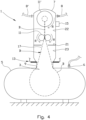
- shows the apparatus after commencing the pulling operation by means of a puling mechanism, wherein a major portion of the bladder has been pulled out;
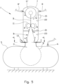
- Fig. 5
- shows the same as
fig. 4 but wherein a cutting device has been activated to perforate the bladder; - Fig. 6
- shows in larger scale a cut through A-A in
fig. 5 ; - Fig. 7
- shows an alternative cutting device of that shown in
fig 5 ; - Fig. 8
- shows an alternative configuration of the cutting device shown in
fig 5 ; and - Fig. 9
- shows the bladder wound onto a drum within the structure.
- In the figures, same or corresponding elements are indicated by same reference numerals and letters.
- Position indications such as for example, upper, lower, upstream and downstream refers to a typical position of use of the apparatus, and as shown in the figures.
- A person skilled in the art will understand that the figures are principle drawings, and that relative proportions between individual elements may be distorted. For example, in the embodiment shown in
figures 1-5 and7-8 the volume of the chamber and the volume defined by the structure are for illustrative purposes substantially the same. However, the volume of the chamber will typically be much larger, for example 100 times or more, than the volume defined by the structure. - For clarity, some of the elements shown may in some of the figures be without reference numerals.
- In the
figures 1 to 9 ,reference numeral 1 denotes an apparatus for controlling a pulling of an inflatable bladder B through anaperture 3 in a wall between achamber 5, here in the form of a vessel, and astructure 7, here in the form of a bladder housing compartment which is desired if the gas within the bladder B is to be collected for example for future use and/or discharged distant from thestructure 7. It should be noted that all required or desired piping and instrumentation of i.a. thevessel 5 and thebladder housing compartment 7 will be obvious to a person skilled in the art and are thus not shown infigures 1-9 . - The
bladder housing compartment 7 is connected to thevessel 5 via aconduit 9 extending from theaperture 3. Theconduit 9 is similar to a so-called manhole. Typically, a diameter of theconduit 9 is 600 mm. - The purpose of the
bladder housing compartment 7 is to store the bladder B prior to insertion into thevessel 5 as shown infig. 1 , and to receive the bladder B as shown infigures 4-5 and7-9 when it has served its purpose, i.e. when thevessel 5 has been purged, as discussed above in relation toWO 2014/070021 A1 . - The
bladder housing compartment 7 is provided with aninternal partition 21 having a central opening therein for receiving a top portion of the bladder B. Thepartition 21 extends radially inwards from an internal wall of thebladder housing compartment 7. Prior to commencing the pulling operation of the bladder B, the bladder B and thepartition 21 serve to divide thebladder housing compartment 7 into anupper portion 22 and alower portion 23, as will be understood from the discussion below. - The
apparatus 1 comprises a pullingmechanism 11, 11', here in the form of a pair ofoblong rollers 11 abutting each other, and a rotatable drum 11'. The rotatable drum 11' is rotated by means of a driving device such as for example an electric, pneumatic or hydraulic motor (not shown). - In a first embodiment the
rollers 11 aretraction rollers 11 configured for rotating in opposite directions as indicated by arrows R infigures 4-5 and7-8 . The rotation is provided by means of a driving device (not shown) such as for example electric, pneumatic or hydraulic motors. In such an embodiment, the rotatable drum 11' is configured for winding the bladder B onto the drum 11' after having passed thetraction rollers 11. In this embodiment the rotatable drum 11' is configured for operating synchronous with thetraction rollers 11 by means of acontrol device 15 operatively connected i.a. thereto. Thecontrol device 15 is typically operated from a remote location on for example a ship. For the sake of clarity, communication lines/signals to and from thecontrol device 15 are not shown. - In a second embodiment the rotatable drum 11' is configured for pulling the bladder B out of the
vessel 5. In such an embodiment therollers 11 may be passive rollers configured for being rotated by means of the bladder B passing therollers 11 while the bladder B is pulled by the rotatable drum 11'. In this second embodiment of the pulling mechanism, thepassive rollers 11 serve as a guidance means. - In a third embodiment, the bladder B is pulled out of the
vessel 5 by means of both thetraction rollers 11 and the rotatable drum 11'. In this third embodiment, the rotatable drum 11' is configured for operating synchronous with thetraction rollers 11 by means of thecontrol device 15. - The
rollers 11, independent of being traction rollers or rollers serving as guidance means, may in one embodiment (not shown) be provided with serrated surfaces configured for cutting the bladder B into a plurality of elongate strips when passing therollers 11. The elongate strips are wound onto the drum 11'. - In all three embodiments of the pulling
mechanism 11, 11', the rotatable drum 11' is configured for being removed from theupper portion 22 of thebladder housing compartment 7 in a manner disclosed inWO 2014/070021 A1 . - The
apparatus 1 further comprises acutting device 13 for providing a slit in a portion of the bladder B after said portion having passed theaperture 3 in the wall of thevessel 5 during the pulling operation, i.e. in a "downstream" side of theaperture 3. Providing the slit in the downstream side of theaperture 3 will substantially prevent that the gas within the bladder B mixes with the gas within thevessel 5. - The cutting
device 13 is movable from a passive position as shown infigures 1 - 4 wherein the cuttingdevice 13 is not in contact with the bladder B, to an active position as shown infigures 5-8 wherein the cutting device penetrates the bladder B. It should be noted that the cutting device shown infig. 7 is shown both in the passive position (indicated by dotted lines) and in the active position. - The movement of the cutting
device 13 both ways between its passive position and its active position is controlled by thecontrol device 15 being further configured for measuring a resistance of the bladder B from passing through the relatively small diameter of theaperture 3 in thevessel 5. - In
fig. 1 , the bladder B is folded and packed in astorage device 17 such as a cartridge, canister or other types of container or box having a size and a shape suitable for efficient storage and transport and thereafter easy handling and installation within thelower portion 23 of thebladder housing compartment 7.Several storage devices 17 are typically stored for example on board a ship for easy use and installation within thebladder housing compartment 7, when needed. - Prior to commencing the pulling operation, a rim BR forming a top portion of a nozzle BN (see for example
fig. 2 ) of the bladder B is connected to the rotatable drum 11' by means of for example arope 18 attached to the rim BR of the bladder B and the rotatable drum 11'. - When the bladder B has been installed in the
bladder housing compartment 7 and prior to commencing the pulling operation of the bladder B, the rim BR of the bladder B abuts an upper surface portion of thepartition 21 at the periphery of the central opening in thepartition 21. Thus, thepartition 21 may support at least some of the weight of the bladder B. More importantly, when the rim BR abuts thepartition 21, a sufficient seal is provided for inflating the bladder B by means of a gas, for example N2, supplied to theupper portion 22 of thebladder housing compartment 7 via agas supply pipe 8. - The
bladder housing compartment 7 is connected to thevessel 5 by a closable sealing means 19 adapted for controllable opening and closing for communication between thebladder housing compartment 7 and the internal of thevessel 5. For illustrative purposes, the closable sealing means 19 are shown infig. 1 only wherein it is indicated as agate valve 19 being in its closed position. - In
fig. 1 the pullingmechanism 11, 11' and thecutting device 13 are inactive. - In
fig. 2 , thegate valve 19 has been opened and a major portion of the bladder B has been inserted, or allowed to "drop", into thevessel 5 and subsequently fully inflated (as indicated by arrows Fi) within thevessel 5. When fully inflated, the bladder B occupies substantially the entire internal volume of thevessel 5. It should be noted that when thegate valve 19 is opened, and prior to inflating the bladder B, a fluid within thelower portion 23 of thebladder housing compartment 7 may mix with the fluid within thevessel 5. However, due to the sealing effect of thepartition 21 and rim BR of the bladder B as discussed above, the fluid within thevessel 5 is substantially prevented from mixing with the fluid within theupper portion 23 of thebladder housing compartment 7. - At least after being fully inflated, the bladder B abuts the
aperture 3 in the wall of thevessel 5 and thus substantially prevents fluid communication between thebladder housing compartment 7, including itslower portion 23, and the internal volume of thevessel 5 defined by an inner surface of thevessel 5 and outer surface of the bladder B. - A vessel purging operation as discussed in
WO 2014/070021 A1 may now commence. -
Fig. 3 shows a situation prior to commencing the pulling operation of the bladder B out of thevessel 5. The bladder B is in the process of being compressed by means of filling a fluid, preferably a gas having a pressure being higher than the pressure within the bladder B, into the space defined by the inner surface of thevessel 5 and the outer surface of the bladder B. The fluid is supplied into thevessel 5 viavessel supply pipe 6. Thus, the bladder B is compressed and most of the gas within the bladder is urged into theupper portion 22 of thebladder housing compartment 7 and out via a conduit 8' for storage in another vessel (not shown) for later use or, depending on the type of gas, ventilated to atmosphere. The fluid flow into thevessel 5 is infig. 3 indicated by arrow Fi and the gas flow out of the bladder B is indicated by arrow Fo. - As discussed above, experiences show that there may be instances in which it is difficult to completely deflate the bladder B, i.e. completely remove all the gas inside the bladder B, before all of the bladder B is pulled through the
aperture 3 and out of thevessel 5. -
Fig. 4 shows a situation wherein the bladder B has been substantially deflated by means of the pressure within thevessel 5, and the pulling process has commenced by activating the pullingmechanism 11, 11' as indicated by arrows R. - The pair of
oblong rollers 11, independent of being traction rollers or guidance means as discussed above, will pucker the bladder B so that a volume of the bladder B at therollers 11 is smaller than an area defined by the periphery of theaperture 3 in thevessel 5. Thus, during the pulling of the bladder B experiences show that the gas will accumulate in the portion of the bladder B still being within thevessel 5, i.e. upstream of theaperture 3. Due to the pulling of the bladder B, the volume available for housing the gas within the bladder B will diminish and the pressure within the bladder B will increase. This increased pressure will result in an increased resistance against the pulling of the bladder B through theaperture 3. - The
apparatus 1 is provided with a measuring device (not shown) for measuring a load on the relevant pullingmechanism 11, 11'. Alternatively, or additionally, the measuring device may be a pressure sensing mechanism arranged in or at a periphery of theaperture 3 in the wall of thevessel 5. The pressure sensing mechanism is responsive to a pressure or load exerted by the bladder B while passing theaperture 3. - If the measuring device for measuring a resistance of the bladder B from passing through the
aperture 3 measures a resistance exceeding a predetermined level, thecontrol device 15 will activate a driving device of the cuttingdevice 13 and move thecutting device 13 from an initial passive position as shown for example infig. 4 , to an active position as shown for example infig. 5 wherein the cuttingdevice 13 penetrates the bladder B in the portion being downstream of theaperture 3, i.e. within thelower portion 23 of thebladder housing compartment 7. - In the embodiments shown in
figures 1-6 and8-9 , the cuttingdevice 13 comprises a sharp object, such as a knife extending from a piston movable within a cylinder (best seen infig. 6 ). Thus, the driving device comprises a fluid pump, for example a hydraulic pump connected to a hydraulic source. As an alternative to said sharp object, the cutting device may for example comprise a rod configured for being heated at least in its active position so that the rod penetrates the bladder B by melting through the wall thereof. However, a cutting device in the form of a sharp object is preferred. - When being penetrated by the cutting
device 13, the gas within the bladder B flows out of the bladder B and into thelower portion 23 of thebladder housing compartment 7. Due to therollers 11 within theupper portion 22 of thebladder housing compartment 7, the bladder will be puckered, and a space will arise between the bladder B and the periphery of the opening in thepartition 21. The compressed gas from within the bladder B flowing into thelower portion 23 of thebladder housing compartment 7, is then allowed to pass said space at thepartition 21 and flow into theupper potion 23 ofbladder housing compartment 7 and out through the conduit 8' as mentioned above. This flow is infigures 5 ,7 , and8 indicated by arrows Fo. - By measuring the resistance of the bladder B from passing through the
aperture 3 either continuously or at certain intervals, for example each five seconds, the cuttingdevice 13 may be controlled both ways between its active and passive positions so that a desired resistance against the pulling is achieved. - It is desirable to substantially prevent that the gas within the
vessel 5 blends with the gas in thebladder housing compartment 7. To achieve this desire, it is important that the bladder B within thevessel 5 seals around theaperture 3 during the pulling operation. Therefore, it is important that the slit(s) provided by the cuttingdevice 13 is/are not too large. This is controlled by thecontrol device 15 in such a manner that if the resistance against pulling of the bladder B is below a predetermined level, the cuttingdevice 13 is retracted to its initial passive position. If the resistance thereafter increases to a level above the predetermined level, the cuttingdevice 13 is again moved to its active position. This process continues until the bladder B is completely pulled out of thevessel 5 and thevalve 19 at theaperture 3 is closed. -
Fig. 6 shows an example of a configuration of the cuttingdevice 13 comprising eight cuttingelements 14 extending radially towards a centerline of theaperture 3 of the vessel and theconduit 9. It should be noted that the cuttingdevice 13 in an alternative embodiment may comprise at least one cutting element. In the embodiment shown, each cuttingelement 14 is connected to a piston of a piston-cylinder arrangement 14' as discussed above. The piston-cylinder arrangements 14' are arranged at the interface between theconduit 9 and a wall of thebladder housing compartment 7. - In the embodiment shown, all eight cutting
elements 14 are in their active position penetrating the bladder B. However, it is preferred that each of or at least opposite pairs of the cuttingelements 14 are configured to be controlled individually by means of thecontrol device 15 operatively connected to the means for measuring resistance of the bladder B through theaperture 3. - Further examples of arrangements of the cutting
device 13 are shown infigures 7 and8 which will be discussed below. - In
fig. 7 , the cuttingdevice 13 comprises rollingknives 14. Each rollingknife 14 is arranged at an end portion of a pivot arm 14' connected to the wall of thelower portion 23 of thebladder housing compartment 7. In the embodiment shown, the arm 14' is configured for movement between a passive position (shown by dotted lines), and an active position wherein the rolling knives penetrates the wall of the bladder B. The movement is provided by means of a hydraulic or pneumatic cylinder controlled by means of thecontrol device 15 as discussed above. - The cutting
device 13 shown infig. 8 is similar to cuttingdevice 13 shown infig. 5 , but inclined downwardly with respect to a pulling direction of the bladder B instead of being substantially perpendicular thereto as indicated infig. 5 . - With respect to the number of cutting
elements 14, thecutting devices 13 shown infigures 7 and8 may be arranged and operated in a similar way as discussed with regards to the embodiment shown infig. 5 andfig. 6 . - Due to the upward movement of the bladder B when pulled out of the
vessel 5, it is desired to provide the slit relatively close to theaperture 3. An "effective working time" of the slit before the slit moves puckered into theupper part 22 of thebladder housing compartment 7 will then be sufficient for serving its purpose of allowing gas to flow out of the bladder B. - In
fig. 9 the bladder B has been pulled out of thevessel 5 and fully wound onto the drum 11' which can then be removed from theupper portion 22 of thebladder housing compartment 7 for example via an openable top portion (not shown) thereof. Thegate valve 19 has been activated to its closed position so thatbladder housing compartment 7 is fluidly isolated from the internal of thevessel 5. - From the above it should be understood that it is important that the rate of gas release from the bladder attained through such controlled slit or cut is not significantly greater than that of the pulling rate of the bladder so that the bladder inside the
vessel 5 is sufficiently inflated to form an effective seal against leakage from thebladder housing compartment 7 into thevessel 5 through theaperture 3. If the gas release rate is too high compared with the pulling rate of the bladder B, the bladder B may deflate more rapidly than its volumetric removal rate fromvessel 5, resulting in loss of sealing of the bladder B against theaperture 3 resulting of gas leakage from thebladder housing compartment 7 intovessel 5. By the term volumetric removal rate is meant the rate at which the remaining volume of the bladder B is reduced inside thevessel 5 as a result of the bladder B being pulled through theaperture 3 and intobladder housing compartment 7. - As will be apparent form the description above, the gas release rate from the bladder can be controlled by at least three different methods.
- A first method of controlling the gas release rate from the bladder B in the
lower portion 23 of thebladder housing compartment 7, is through monitoring the torque applied to the pullingmechanism 11, 11' and thus apply a selective degree of cut of the bladder B in thelower portion 23 of thebladder housing compartment 7 as a function of required torque above a certain threshold level. Once the required gas release rate is achieved the required torque is reduced and thus the degree of selective cut is similarly reduced. - A second method of controlling the gas release rate from the bladder B in the
lower portion 23 of thebladder housing compartment 7 is through maintaining a certain degree torque applied to the pullingmechanism 11, 11'. Once a certain torque level is exceeded, the selective cut is applied in increasing degree until the torque level is reduced to within acceptable or desired limits. In this context the torque level of the pullingmechanism 11, 11' will be a proxy for the degree of sealing pressure from the bladder B against theaperture 3 on the inside ofvessel 5. The degree of selective cut of the bladder B in thelower portion 23 of thebladder housing compartment 7 is successively reduced in line with reduced degree of torque requirements. - A third method of controlling the gas release rate from the bladder B in the
lower portion 23 of thebladder housing compartment 7 is through maintaining a constant volumetric extraction rate of the bladder B through controlling the speed of therollers 11 and/or the rotatable drum 11' whilst monitoring the required torque applied thereto. Once a certain torque level is exceeded, selective slit(s) is/are applied in thelower portion 23 of thebladder housing compartment 7 whilst maintaining the applied torque of therollers 11 and/or rotatable drum 11' below a predetermined limit. The torque is maintained by varying the rotational speed thereof such that neither the extraction rate of the bladder B nor the upper torque level is exceeded. Once the torque level is below a predetermined level and the maximum predetermined rotational speed of therollers 11 and/or rotatable drum 11' is achieved, the degree of selective cut through the wall of the bladder B is reduced or withdrawn. - It should be noted that the above-mentioned embodiments illustrate rather than limit the invention, and that those skilled in the art will be able to design many alternative embodiments without departing from the scope of the appended claims. In the claims, any reference signs placed between parentheses shall not be construed as limiting the claim. Use of the verb "comprise" and its conjugations does not exclude the presence of elements or steps other than those stated in a claim. The article "a" or "an" preceding an element does not exclude the presence of a plurality of such elements.
- The mere fact that certain measures are recited in mutually different dependent claims does not indicate that a combination of these measures cannot be used to advantage.
Claims (8)
- An apparatus (1) for controlling a pulling of an inflatable bladder (B) through an aperture (3) in a wall between a chamber (5) and a structure (7) arranged on an outside of the chamber (5), wherein the apparatus (1) comprises:- a pulling mechanism (11, 11') for pulling the bladder (B) through the aperture (3);- a cutting device (13) for providing a slit in a portion of the bladder (B) after said portion having passed the aperture (3), the cutting device (13) being responsive to a resistance of the bladder (B) against passing through the aperture (3), so that the cutting device (13) is activated and provides the slit if the resistance exceeds a predetermined level.
- The apparatus (1) according to claim 1, wherein the resistance is measured by measuring a load on the pulling mechanism.
- The apparatus (1) according to claim 1, wherein the resistance is measured by means of a pressure sensing mechanism arranged in or at a periphery of the aperture (3), the pressure sensing mechanism configured for measuring a pressure exerted by the bladder (B).
- The apparatus (1) according to any one of claims 1 to 3, comprising a control device (15) for further controlling a pulling rate of the pulling mechanism (11, 11'), the control device (15) being responsive to a resistance of the bladder (B) from passing through the aperture (3) so that the pulling rate is increased if the resistance is reduced, and vice versa.
- The apparatus (1) according to any one of claims 1 to 4, wherein the cutting device (13) is configured for providing one or more slits along an axis being substantially in parallel with a moving direction of the bladder (B) through the aperture (3).
- The apparatus (1) according to any one of claims 1 to 5, wherein the pulling mechanism (11, 11') is configured for puckering the bladder (B) so that a volume of the bladder (B) at the pulling mechanism (11) is smaller than an area defined by a periphery of the aperture (3).
- A method for pulling an inflatable bladder (B) through an aperture (3) in a wall between a chamber (5) and a structure (7), wherein the method comprises:- bringing a portion of the bladder (B) in engagement with a pulling device (11, 11') configured for pulling the bladder (B) through the aperture (3) between the chamber (5) and the structure (7) arranged on an outside of the chamber (5);- activating the pulling device (11, 11') and measuring by means of a measuring device (15) a resistance of the bladder (B) against passing through the aperture (3); and- if the measured resistance exceeds a predetermined level, activating a cutting device (13) configured for providing a slit in a portion of the bladder (B) that has been pulled through the aperture (3).
- The method according to claim 7, wherein, after activating the cutting device (13), the method further comprises controlling a pulling rate so that the resistance of the bladder (B) against passing through the aperture (3) is within a predetermined range.
Applications Claiming Priority (2)
| Application Number | Priority Date | Filing Date | Title |
|---|---|---|---|
| NO20190096A NO345292B1 (en) | 2019-01-25 | 2019-01-25 | An apparatus and a method for controlling a pulling of an inflatable bladder through an aperture |
| PCT/NO2020/050011 WO2020153852A1 (en) | 2019-01-25 | 2020-01-23 | An apparatus and a method for controlling a pulling of an inflatable bladder through an aperture |
Publications (3)
| Publication Number | Publication Date |
|---|---|
| EP3914850A1 EP3914850A1 (en) | 2021-12-01 |
| EP3914850A4 EP3914850A4 (en) | 2022-10-26 |
| EP3914850B1 true EP3914850B1 (en) | 2023-08-02 |
Family
ID=71736483
Family Applications (1)
| Application Number | Title | Priority Date | Filing Date |
|---|---|---|---|
| EP20744266.6A Active EP3914850B1 (en) | 2019-01-25 | 2020-01-23 | An apparatus and a method for controlling a pulling of an inflatable bladder through an aperture |
Country Status (3)
| Country | Link |
|---|---|
| EP (1) | EP3914850B1 (en) |
| NO (1) | NO345292B1 (en) |
| WO (1) | WO2020153852A1 (en) |
Families Citing this family (2)
| Publication number | Priority date | Publication date | Assignee | Title |
|---|---|---|---|---|
| NO346713B1 (en) * | 2021-05-20 | 2022-12-05 | Ravndal & Moore Projects As | An apparatus and a method for extracting a bladder through a constriction |
| NO349002B1 (en) * | 2024-07-16 | 2025-08-25 | Vecs As | An inflatable bladder, a system comprising the bladder, and a method for bringing the bladder into and out of a vessel |
Family Cites Families (9)
| Publication number | Priority date | Publication date | Assignee | Title |
|---|---|---|---|---|
| BE542014A (en) * | 1954-10-18 | |||
| JPS51150551A (en) * | 1975-06-19 | 1976-12-24 | Nittetsu Kaatenoole Kk | An electro deposition method of aluminium or aluminium alloys by alter nating current |
| GB1543579A (en) * | 1975-07-02 | 1979-04-04 | British Petroleum Co | Storage tank |
| JPS58180897A (en) * | 1982-04-19 | 1983-10-22 | Kawasaki Steel Corp | Removing method for residual gas in gas holder |
| US7021488B2 (en) * | 2003-03-31 | 2006-04-04 | Matheson Tri-Gas, Inc. | Pressure vessel for compressed gases utilizing a replaceable and flexible liner |
| DE102004043380A1 (en) * | 2004-09-03 | 2006-03-09 | SCHÄFER, Friedrich | Fluid device for food stuff industry, has constituent parts that are volume-flexible fillable bag, tubes, manometer, valve and coupler, where storage of fluids in containers with rigid volume-limited volumetric capacity is made possible |
| NO322558B1 (en) * | 2004-09-21 | 2006-10-23 | Ola Ravndal | Method of using volume displacing device when changing load in a means of transport |
| WO2014070021A1 (en) * | 2012-11-05 | 2014-05-08 | Environgas As | A method and an apparatus for deployment of a bladder into and out of a vessel |
| FR2998268B1 (en) * | 2012-11-19 | 2015-07-17 | Eurocopter France | FUEL STORAGE DEVICE, AIRCRAFT AND METHOD |
-
2019
- 2019-01-25 NO NO20190096A patent/NO345292B1/en unknown
-
2020
- 2020-01-23 WO PCT/NO2020/050011 patent/WO2020153852A1/en not_active Ceased
- 2020-01-23 EP EP20744266.6A patent/EP3914850B1/en active Active
Also Published As
| Publication number | Publication date |
|---|---|
| NO20190096A1 (en) | 2020-07-27 |
| EP3914850A4 (en) | 2022-10-26 |
| WO2020153852A1 (en) | 2020-07-30 |
| NO345292B1 (en) | 2020-11-30 |
| EP3914850A1 (en) | 2021-12-01 |
Similar Documents
| Publication | Publication Date | Title |
|---|---|---|
| CN106079583B (en) | Operating system of air charging device of air buffer body and operating method thereof | |
| EP1466720B1 (en) | Process for forming fluid filled units and series of fluid filled units | |
| AU573241B2 (en) | A high speed evacuation chamber packaging machine | |
| MX2012008056A (en) | Systems and methods for cleaning body cavities. | |
| US20190248095A1 (en) | Inflating stick and processing machine | |
| NO345292B1 (en) | An apparatus and a method for controlling a pulling of an inflatable bladder through an aperture | |
| ES2402979T3 (en) | Device for extracting liquids from a container | |
| US9067378B2 (en) | Inflation and sealing device with rotary cutter | |
| JPS63203521A (en) | Method and device for manufacturing gas-flushed packaging | |
| CA2641774A1 (en) | Inflation valve assembly | |
| WO2013074782A1 (en) | Apparatus and method for displacing air from wine containers | |
| CN208071018U (en) | A kind of tension-adjusting gear of PVC tarpaulins | |
| CN2344433Y (en) | Air bag for blocking leakage | |
| JP2020518508A (en) | Cover device and thruster | |
| US4666413A (en) | Life-saving appliance with a gas-tight covering | |
| WO2016195742A1 (en) | On-board re-inflatable containment boom and control system | |
| BR112017016771B1 (en) | PACKAGING APPLIANCE, AND PACKAGING PROCESS PERFORMED USING SAID APPLIANCE | |
| NO346713B1 (en) | An apparatus and a method for extracting a bladder through a constriction | |
| GB2064703A (en) | Unblocking and repairing conduits | |
| US5082236A (en) | Tablet or capsule drop tube assembly | |
| US20180016762A1 (en) | On-board spool-able re-useable containment boom and control system | |
| KR102182480B1 (en) | Supplying a dispensing device for loading a refinery and/or petrochemical reactor with solid particles | |
| US20250296748A1 (en) | An opening system for containers that are under pressure | |
| AU2015396962B2 (en) | On-board re-inflatable containment boom system and method | |
| DK172028B1 (en) | Apparatus for releasing a rescue equipment |
Legal Events
| Date | Code | Title | Description |
|---|---|---|---|
| STAA | Information on the status of an ep patent application or granted ep patent |
Free format text: STATUS: THE INTERNATIONAL PUBLICATION HAS BEEN MADE |
|
| PUAI | Public reference made under article 153(3) epc to a published international application that has entered the european phase |
Free format text: ORIGINAL CODE: 0009012 |
|
| STAA | Information on the status of an ep patent application or granted ep patent |
Free format text: STATUS: REQUEST FOR EXAMINATION WAS MADE |
|
| 17P | Request for examination filed |
Effective date: 20210810 |
|
| AK | Designated contracting states |
Kind code of ref document: A1 Designated state(s): AL AT BE BG CH CY CZ DE DK EE ES FI FR GB GR HR HU IE IS IT LI LT LU LV MC MK MT NL NO PL PT RO RS SE SI SK SM TR |
|
| DAV | Request for validation of the european patent (deleted) | ||
| DAX | Request for extension of the european patent (deleted) | ||
| A4 | Supplementary search report drawn up and despatched |
Effective date: 20220926 |
|
| RIC1 | Information provided on ipc code assigned before grant |
Ipc: F17C 3/00 20060101ALI20220920BHEP Ipc: F17C 1/02 20060101ALI20220920BHEP Ipc: B65D 90/22 20060101ALI20220920BHEP Ipc: F17C 7/00 20060101AFI20220920BHEP |
|
| GRAP | Despatch of communication of intention to grant a patent |
Free format text: ORIGINAL CODE: EPIDOSNIGR1 |
|
| STAA | Information on the status of an ep patent application or granted ep patent |
Free format text: STATUS: GRANT OF PATENT IS INTENDED |
|
| INTG | Intention to grant announced |
Effective date: 20230327 |
|
| GRAS | Grant fee paid |
Free format text: ORIGINAL CODE: EPIDOSNIGR3 |
|
| GRAA | (expected) grant |
Free format text: ORIGINAL CODE: 0009210 |
|
| STAA | Information on the status of an ep patent application or granted ep patent |
Free format text: STATUS: THE PATENT HAS BEEN GRANTED |
|
| AK | Designated contracting states |
Kind code of ref document: B1 Designated state(s): AL AT BE BG CH CY CZ DE DK EE ES FI FR GB GR HR HU IE IS IT LI LT LU LV MC MK MT NL NO PL PT RO RS SE SI SK SM TR |
|
| REG | Reference to a national code |
Ref country code: GB Ref legal event code: FG4D |
|
| REG | Reference to a national code |
Ref country code: CH Ref legal event code: EP |
|
| REG | Reference to a national code |
Ref country code: DE Ref legal event code: R096 Ref document number: 602020015049 Country of ref document: DE |
|
| REG | Reference to a national code |
Ref country code: IE Ref legal event code: FG4D |
|
| REG | Reference to a national code |
Ref country code: NL Ref legal event code: FP |
|
| P01 | Opt-out of the competence of the unified patent court (upc) registered |
Effective date: 20230821 |
|
| REG | Reference to a national code |
Ref country code: LT Ref legal event code: MG9D |
|
| REG | Reference to a national code |
Ref country code: AT Ref legal event code: MK05 Ref document number: 1595135 Country of ref document: AT Kind code of ref document: T Effective date: 20230802 |
|
| PG25 | Lapsed in a contracting state [announced via postgrant information from national office to epo] |
Ref country code: GR Free format text: LAPSE BECAUSE OF FAILURE TO SUBMIT A TRANSLATION OF THE DESCRIPTION OR TO PAY THE FEE WITHIN THE PRESCRIBED TIME-LIMIT Effective date: 20231103 |
|
| PG25 | Lapsed in a contracting state [announced via postgrant information from national office to epo] |
Ref country code: IS Free format text: LAPSE BECAUSE OF FAILURE TO SUBMIT A TRANSLATION OF THE DESCRIPTION OR TO PAY THE FEE WITHIN THE PRESCRIBED TIME-LIMIT Effective date: 20231202 |
|
| PG25 | Lapsed in a contracting state [announced via postgrant information from national office to epo] |
Ref country code: SE Free format text: LAPSE BECAUSE OF FAILURE TO SUBMIT A TRANSLATION OF THE DESCRIPTION OR TO PAY THE FEE WITHIN THE PRESCRIBED TIME-LIMIT Effective date: 20230802 Ref country code: RS Free format text: LAPSE BECAUSE OF FAILURE TO SUBMIT A TRANSLATION OF THE DESCRIPTION OR TO PAY THE FEE WITHIN THE PRESCRIBED TIME-LIMIT Effective date: 20230802 Ref country code: PT Free format text: LAPSE BECAUSE OF FAILURE TO SUBMIT A TRANSLATION OF THE DESCRIPTION OR TO PAY THE FEE WITHIN THE PRESCRIBED TIME-LIMIT Effective date: 20231204 Ref country code: NO Free format text: LAPSE BECAUSE OF FAILURE TO SUBMIT A TRANSLATION OF THE DESCRIPTION OR TO PAY THE FEE WITHIN THE PRESCRIBED TIME-LIMIT Effective date: 20231102 Ref country code: LV Free format text: LAPSE BECAUSE OF FAILURE TO SUBMIT A TRANSLATION OF THE DESCRIPTION OR TO PAY THE FEE WITHIN THE PRESCRIBED TIME-LIMIT Effective date: 20230802 Ref country code: LT Free format text: LAPSE BECAUSE OF FAILURE TO SUBMIT A TRANSLATION OF THE DESCRIPTION OR TO PAY THE FEE WITHIN THE PRESCRIBED TIME-LIMIT Effective date: 20230802 Ref country code: IS Free format text: LAPSE BECAUSE OF FAILURE TO SUBMIT A TRANSLATION OF THE DESCRIPTION OR TO PAY THE FEE WITHIN THE PRESCRIBED TIME-LIMIT Effective date: 20231202 Ref country code: HR Free format text: LAPSE BECAUSE OF FAILURE TO SUBMIT A TRANSLATION OF THE DESCRIPTION OR TO PAY THE FEE WITHIN THE PRESCRIBED TIME-LIMIT Effective date: 20230802 Ref country code: GR Free format text: LAPSE BECAUSE OF FAILURE TO SUBMIT A TRANSLATION OF THE DESCRIPTION OR TO PAY THE FEE WITHIN THE PRESCRIBED TIME-LIMIT Effective date: 20231103 Ref country code: FI Free format text: LAPSE BECAUSE OF FAILURE TO SUBMIT A TRANSLATION OF THE DESCRIPTION OR TO PAY THE FEE WITHIN THE PRESCRIBED TIME-LIMIT Effective date: 20230802 Ref country code: AT Free format text: LAPSE BECAUSE OF FAILURE TO SUBMIT A TRANSLATION OF THE DESCRIPTION OR TO PAY THE FEE WITHIN THE PRESCRIBED TIME-LIMIT Effective date: 20230802 |
|
| PG25 | Lapsed in a contracting state [announced via postgrant information from national office to epo] |
Ref country code: PL Free format text: LAPSE BECAUSE OF FAILURE TO SUBMIT A TRANSLATION OF THE DESCRIPTION OR TO PAY THE FEE WITHIN THE PRESCRIBED TIME-LIMIT Effective date: 20230802 |
|
| PG25 | Lapsed in a contracting state [announced via postgrant information from national office to epo] |
Ref country code: ES Free format text: LAPSE BECAUSE OF FAILURE TO SUBMIT A TRANSLATION OF THE DESCRIPTION OR TO PAY THE FEE WITHIN THE PRESCRIBED TIME-LIMIT Effective date: 20230802 |
|
| PG25 | Lapsed in a contracting state [announced via postgrant information from national office to epo] |
Ref country code: SM Free format text: LAPSE BECAUSE OF FAILURE TO SUBMIT A TRANSLATION OF THE DESCRIPTION OR TO PAY THE FEE WITHIN THE PRESCRIBED TIME-LIMIT Effective date: 20230802 Ref country code: RO Free format text: LAPSE BECAUSE OF FAILURE TO SUBMIT A TRANSLATION OF THE DESCRIPTION OR TO PAY THE FEE WITHIN THE PRESCRIBED TIME-LIMIT Effective date: 20230802 Ref country code: ES Free format text: LAPSE BECAUSE OF FAILURE TO SUBMIT A TRANSLATION OF THE DESCRIPTION OR TO PAY THE FEE WITHIN THE PRESCRIBED TIME-LIMIT Effective date: 20230802 Ref country code: EE Free format text: LAPSE BECAUSE OF FAILURE TO SUBMIT A TRANSLATION OF THE DESCRIPTION OR TO PAY THE FEE WITHIN THE PRESCRIBED TIME-LIMIT Effective date: 20230802 Ref country code: DK Free format text: LAPSE BECAUSE OF FAILURE TO SUBMIT A TRANSLATION OF THE DESCRIPTION OR TO PAY THE FEE WITHIN THE PRESCRIBED TIME-LIMIT Effective date: 20230802 Ref country code: CZ Free format text: LAPSE BECAUSE OF FAILURE TO SUBMIT A TRANSLATION OF THE DESCRIPTION OR TO PAY THE FEE WITHIN THE PRESCRIBED TIME-LIMIT Effective date: 20230802 Ref country code: SK Free format text: LAPSE BECAUSE OF FAILURE TO SUBMIT A TRANSLATION OF THE DESCRIPTION OR TO PAY THE FEE WITHIN THE PRESCRIBED TIME-LIMIT Effective date: 20230802 |
|
| PGFP | Annual fee paid to national office [announced via postgrant information from national office to epo] |
Ref country code: GB Payment date: 20240118 Year of fee payment: 5 |
|
| REG | Reference to a national code |
Ref country code: DE Ref legal event code: R097 Ref document number: 602020015049 Country of ref document: DE |
|
| PG25 | Lapsed in a contracting state [announced via postgrant information from national office to epo] |
Ref country code: IT Free format text: LAPSE BECAUSE OF FAILURE TO SUBMIT A TRANSLATION OF THE DESCRIPTION OR TO PAY THE FEE WITHIN THE PRESCRIBED TIME-LIMIT Effective date: 20230802 |
|
| PGFP | Annual fee paid to national office [announced via postgrant information from national office to epo] |
Ref country code: FR Payment date: 20240115 Year of fee payment: 5 Ref country code: BE Payment date: 20240126 Year of fee payment: 5 |
|
| PLBE | No opposition filed within time limit |
Free format text: ORIGINAL CODE: 0009261 |
|
| STAA | Information on the status of an ep patent application or granted ep patent |
Free format text: STATUS: NO OPPOSITION FILED WITHIN TIME LIMIT |
|
| 26N | No opposition filed |
Effective date: 20240503 |
|
| PG25 | Lapsed in a contracting state [announced via postgrant information from national office to epo] |
Ref country code: SI Free format text: LAPSE BECAUSE OF FAILURE TO SUBMIT A TRANSLATION OF THE DESCRIPTION OR TO PAY THE FEE WITHIN THE PRESCRIBED TIME-LIMIT Effective date: 20230802 |
|
| PG25 | Lapsed in a contracting state [announced via postgrant information from national office to epo] |
Ref country code: MC Free format text: LAPSE BECAUSE OF FAILURE TO SUBMIT A TRANSLATION OF THE DESCRIPTION OR TO PAY THE FEE WITHIN THE PRESCRIBED TIME-LIMIT Effective date: 20230802 |
|
| PG25 | Lapsed in a contracting state [announced via postgrant information from national office to epo] |
Ref country code: MC Free format text: LAPSE BECAUSE OF FAILURE TO SUBMIT A TRANSLATION OF THE DESCRIPTION OR TO PAY THE FEE WITHIN THE PRESCRIBED TIME-LIMIT Effective date: 20230802 |
|
| REG | Reference to a national code |
Ref country code: CH Ref legal event code: PL |
|
| PG25 | Lapsed in a contracting state [announced via postgrant information from national office to epo] |
Ref country code: LU Free format text: LAPSE BECAUSE OF NON-PAYMENT OF DUE FEES Effective date: 20240123 |
|
| PG25 | Lapsed in a contracting state [announced via postgrant information from national office to epo] |
Ref country code: LU Free format text: LAPSE BECAUSE OF NON-PAYMENT OF DUE FEES Effective date: 20240123 |
|
| PG25 | Lapsed in a contracting state [announced via postgrant information from national office to epo] |
Ref country code: CH Free format text: LAPSE BECAUSE OF NON-PAYMENT OF DUE FEES Effective date: 20240131 |
|
| PG25 | Lapsed in a contracting state [announced via postgrant information from national office to epo] |
Ref country code: CH Free format text: LAPSE BECAUSE OF NON-PAYMENT OF DUE FEES Effective date: 20240131 |
|
| PG25 | Lapsed in a contracting state [announced via postgrant information from national office to epo] |
Ref country code: BG Free format text: LAPSE BECAUSE OF FAILURE TO SUBMIT A TRANSLATION OF THE DESCRIPTION OR TO PAY THE FEE WITHIN THE PRESCRIBED TIME-LIMIT Effective date: 20230802 |
|
| PG25 | Lapsed in a contracting state [announced via postgrant information from national office to epo] |
Ref country code: BG Free format text: LAPSE BECAUSE OF FAILURE TO SUBMIT A TRANSLATION OF THE DESCRIPTION OR TO PAY THE FEE WITHIN THE PRESCRIBED TIME-LIMIT Effective date: 20230802 |
|
| PG25 | Lapsed in a contracting state [announced via postgrant information from national office to epo] |
Ref country code: IE Free format text: LAPSE BECAUSE OF NON-PAYMENT OF DUE FEES Effective date: 20240123 |
|
| PG25 | Lapsed in a contracting state [announced via postgrant information from national office to epo] |
Ref country code: IE Free format text: LAPSE BECAUSE OF NON-PAYMENT OF DUE FEES Effective date: 20240123 |
|
| PG25 | Lapsed in a contracting state [announced via postgrant information from national office to epo] |
Ref country code: CY Free format text: LAPSE BECAUSE OF FAILURE TO SUBMIT A TRANSLATION OF THE DESCRIPTION OR TO PAY THE FEE WITHIN THE PRESCRIBED TIME-LIMIT; INVALID AB INITIO Effective date: 20200123 |
|
| PG25 | Lapsed in a contracting state [announced via postgrant information from national office to epo] |
Ref country code: HU Free format text: LAPSE BECAUSE OF FAILURE TO SUBMIT A TRANSLATION OF THE DESCRIPTION OR TO PAY THE FEE WITHIN THE PRESCRIBED TIME-LIMIT; INVALID AB INITIO Effective date: 20200123 |
|
| GBPC | Gb: european patent ceased through non-payment of renewal fee |
Effective date: 20250123 |
|
| PG25 | Lapsed in a contracting state [announced via postgrant information from national office to epo] |
Ref country code: BE Free format text: LAPSE BECAUSE OF NON-PAYMENT OF DUE FEES Effective date: 20250131 Ref country code: GB Free format text: LAPSE BECAUSE OF NON-PAYMENT OF DUE FEES Effective date: 20250123 |
|
| PG25 | Lapsed in a contracting state [announced via postgrant information from national office to epo] |
Ref country code: FR Free format text: LAPSE BECAUSE OF NON-PAYMENT OF DUE FEES Effective date: 20250131 |
|
| REG | Reference to a national code |
Ref country code: BE Ref legal event code: MM Effective date: 20250131 |
|
| PG25 | Lapsed in a contracting state [announced via postgrant information from national office to epo] |
Ref country code: TR Free format text: LAPSE BECAUSE OF FAILURE TO SUBMIT A TRANSLATION OF THE DESCRIPTION OR TO PAY THE FEE WITHIN THE PRESCRIBED TIME-LIMIT Effective date: 20230802 |
|
| PGFP | Annual fee paid to national office [announced via postgrant information from national office to epo] |
Ref country code: NL Payment date: 20260116 Year of fee payment: 7 |
|
| PGFP | Annual fee paid to national office [announced via postgrant information from national office to epo] |
Ref country code: DE Payment date: 20260115 Year of fee payment: 7 |