EP3914845B1 - Flansch für einen schlauch - Google Patents
Flansch für einen schlauch Download PDFInfo
- Publication number
- EP3914845B1 EP3914845B1 EP20702074.4A EP20702074A EP3914845B1 EP 3914845 B1 EP3914845 B1 EP 3914845B1 EP 20702074 A EP20702074 A EP 20702074A EP 3914845 B1 EP3914845 B1 EP 3914845B1
- Authority
- EP
- European Patent Office
- Prior art keywords
- locking element
- annular
- hose
- flange
- flange body
- Prior art date
- Legal status (The legal status is an assumption and is not a legal conclusion. Google has not performed a legal analysis and makes no representation as to the accuracy of the status listed.)
- Active
Links
Images


Classifications
-
- F—MECHANICAL ENGINEERING; LIGHTING; HEATING; WEAPONS; BLASTING
- F16—ENGINEERING ELEMENTS AND UNITS; GENERAL MEASURES FOR PRODUCING AND MAINTAINING EFFECTIVE FUNCTIONING OF MACHINES OR INSTALLATIONS; THERMAL INSULATION IN GENERAL
- F16L—PIPES; JOINTS OR FITTINGS FOR PIPES; SUPPORTS FOR PIPES, CABLES OR PROTECTIVE TUBING; MEANS FOR THERMAL INSULATION IN GENERAL
- F16L23/00—Flanged joints
- F16L23/02—Flanged joints the flanges being connected by members tensioned axially
- F16L23/024—Flanged joints the flanges being connected by members tensioned axially characterised by how the flanges are joined to, or form an extension of, the pipes
- F16L23/028—Flanged joints the flanges being connected by members tensioned axially characterised by how the flanges are joined to, or form an extension of, the pipes the flanges being held against a shoulder
-
- F—MECHANICAL ENGINEERING; LIGHTING; HEATING; WEAPONS; BLASTING
- F16—ENGINEERING ELEMENTS AND UNITS; GENERAL MEASURES FOR PRODUCING AND MAINTAINING EFFECTIVE FUNCTIONING OF MACHINES OR INSTALLATIONS; THERMAL INSULATION IN GENERAL
- F16L—PIPES; JOINTS OR FITTINGS FOR PIPES; SUPPORTS FOR PIPES, CABLES OR PROTECTIVE TUBING; MEANS FOR THERMAL INSULATION IN GENERAL
- F16L23/00—Flanged joints
- F16L23/02—Flanged joints the flanges being connected by members tensioned axially
- F16L23/024—Flanged joints the flanges being connected by members tensioned axially characterised by how the flanges are joined to, or form an extension of, the pipes
- F16L23/028—Flanged joints the flanges being connected by members tensioned axially characterised by how the flanges are joined to, or form an extension of, the pipes the flanges being held against a shoulder
- F16L23/0286—Flanged joints the flanges being connected by members tensioned axially characterised by how the flanges are joined to, or form an extension of, the pipes the flanges being held against a shoulder the shoulder not being formed from the pipe
-
- F—MECHANICAL ENGINEERING; LIGHTING; HEATING; WEAPONS; BLASTING
- F16—ENGINEERING ELEMENTS AND UNITS; GENERAL MEASURES FOR PRODUCING AND MAINTAINING EFFECTIVE FUNCTIONING OF MACHINES OR INSTALLATIONS; THERMAL INSULATION IN GENERAL
- F16L—PIPES; JOINTS OR FITTINGS FOR PIPES; SUPPORTS FOR PIPES, CABLES OR PROTECTIVE TUBING; MEANS FOR THERMAL INSULATION IN GENERAL
- F16L19/00—Joints in which sealing surfaces are pressed together by means of a member, e.g. a swivel nut, screwed on, or into, one of the joint parts
- F16L19/02—Pipe ends provided with collars or flanges, integral with the pipe or not, pressed together by a screwed member
-
- F—MECHANICAL ENGINEERING; LIGHTING; HEATING; WEAPONS; BLASTING
- F16—ENGINEERING ELEMENTS AND UNITS; GENERAL MEASURES FOR PRODUCING AND MAINTAINING EFFECTIVE FUNCTIONING OF MACHINES OR INSTALLATIONS; THERMAL INSULATION IN GENERAL
- F16L—PIPES; JOINTS OR FITTINGS FOR PIPES; SUPPORTS FOR PIPES, CABLES OR PROTECTIVE TUBING; MEANS FOR THERMAL INSULATION IN GENERAL
- F16L23/00—Flanged joints
-
- F—MECHANICAL ENGINEERING; LIGHTING; HEATING; WEAPONS; BLASTING
- F16—ENGINEERING ELEMENTS AND UNITS; GENERAL MEASURES FOR PRODUCING AND MAINTAINING EFFECTIVE FUNCTIONING OF MACHINES OR INSTALLATIONS; THERMAL INSULATION IN GENERAL
- F16L—PIPES; JOINTS OR FITTINGS FOR PIPES; SUPPORTS FOR PIPES, CABLES OR PROTECTIVE TUBING; MEANS FOR THERMAL INSULATION IN GENERAL
- F16L23/00—Flanged joints
- F16L23/003—Auxiliary devices
-
- F—MECHANICAL ENGINEERING; LIGHTING; HEATING; WEAPONS; BLASTING
- F16—ENGINEERING ELEMENTS AND UNITS; GENERAL MEASURES FOR PRODUCING AND MAINTAINING EFFECTIVE FUNCTIONING OF MACHINES OR INSTALLATIONS; THERMAL INSULATION IN GENERAL
- F16L—PIPES; JOINTS OR FITTINGS FOR PIPES; SUPPORTS FOR PIPES, CABLES OR PROTECTIVE TUBING; MEANS FOR THERMAL INSULATION IN GENERAL
- F16L33/00—Arrangements for connecting hoses to rigid members; Rigid hose-connectors, i.e. single members engaging both hoses
- F16L33/26—Arrangements for connecting hoses to rigid members; Rigid hose-connectors, i.e. single members engaging both hoses specially adapted for hoses made of metal
-
- F—MECHANICAL ENGINEERING; LIGHTING; HEATING; WEAPONS; BLASTING
- F16—ENGINEERING ELEMENTS AND UNITS; GENERAL MEASURES FOR PRODUCING AND MAINTAINING EFFECTIVE FUNCTIONING OF MACHINES OR INSTALLATIONS; THERMAL INSULATION IN GENERAL
- F16L—PIPES; JOINTS OR FITTINGS FOR PIPES; SUPPORTS FOR PIPES, CABLES OR PROTECTIVE TUBING; MEANS FOR THERMAL INSULATION IN GENERAL
- F16L33/00—Arrangements for connecting hoses to rigid members; Rigid hose-connectors, i.e. single members engaging both hoses
- F16L33/28—Arrangements for connecting hoses to rigid members; Rigid hose-connectors, i.e. single members engaging both hoses for hoses with one end terminating in a radial flange or collar
-
- F—MECHANICAL ENGINEERING; LIGHTING; HEATING; WEAPONS; BLASTING
- F16—ENGINEERING ELEMENTS AND UNITS; GENERAL MEASURES FOR PRODUCING AND MAINTAINING EFFECTIVE FUNCTIONING OF MACHINES OR INSTALLATIONS; THERMAL INSULATION IN GENERAL
- F16L—PIPES; JOINTS OR FITTINGS FOR PIPES; SUPPORTS FOR PIPES, CABLES OR PROTECTIVE TUBING; MEANS FOR THERMAL INSULATION IN GENERAL
- F16L25/00—Construction or details of pipe joints not provided for in, or of interest apart from, groups F16L13/00 - F16L23/00
- F16L25/0036—Joints for corrugated pipes
Definitions
- the invention relates to a flange for a hose according to the preamble of claim 1.
- Such a flange is known, for example, from US 2004/0187543 A1 in which the couplings are formed by screws or US 3 934 902 A in which the couplings are formed by a threaded ring.
- hoses like rubber hoses
- a flange can be embedded in the rubber hoses to ensure a good connection between the hose and the flange.
- embedding a flange in a rubber hose must be done during the manufacturing of the hose and at such a moment in time it is often not known how the hose will be used.
- the flange is manufactured as two arc shaped elements, which together from an annular flange.
- the two arc shaped elements have overlapping parts in the axial direction with which the arc shaped elements are bolted together and positioned in the circumferential groove of the hose.
- the disadvantage of this construction is that the overlapping parts of the arc shaped elements have a reduced thickness, i.e. half of the thickness of the flange, which is the weakest point of the flange.
- a flange for a hose according to claim 1 which flange comprises:
- the flange according to the invention has a single piece annular flange body, which does not have any overlapping parts, which reduce the thickness of the flange.
- the central hose opening is dimensioned such that a hose can be inserted into the central hose opening without any deformation.
- the annular locking element of the flange according to the invention is composed out of at least two arc shaped locking element parts, which can be positioned into a circumferential groove of a hose end.
- the annular flange body can be shifted over the annular locking element to keep the annular locking element in position.
- the couplings ensure that the annular flange body is coupled to the annular locking element and ensures that the annular flange body and annular locking element can no longer shift relative to each other, resulting in a flange, which extends into the circumferential groove at the hose end.
- the flange according to the invention extends into the circumferential groove and because the flange has a single piece annular flange body, the flange has an even strength distributed along the circumference of the flange and as a result the thickness of the flange can be optimized.
- the first coupling part is a groove extending in axial direction from a first end surface of the annular flange body, wherein the length of the groove is smaller than the thickness of the annular flange body and wherein the second coupling part is a protrusion arranged on the radially outer surface of the respective locking element part, which protrusion has in axial direction a cross-section corresponding to the cross-section of the groove.
- the groove does not extend over the full width of the annular flange body and because the protrusions correspond to the groove in cross-section it is possible to tighten the annular flange body against another flange body or the like, such that the hose end is compressed also against the other flange body, causing a reliable seal.
- the cross-section of the protrusion and the cross-section of the groove is T-shaped.
- the outer diameter of the annular locking element corresponds with the diameter of the central hose opening. With corresponding diameters, it is possible to provide a tight fit of the annular locking element in the annular flange body.
- the annular flange body has a number of axially extending through holes evenly positioned along the circumference of the annular flange body.
- Bolts can be extended through the through holes to tighten the flange according to the invention against another flange.
- the invention also relates to a combination of a flange according to the invention and a hose having an outer diameter smaller than the diameter of the central hose opening and larger than the inner diameter of the annular locking element, which hose has on an end a circumferential groove, in which the annular locking element is at least partially accommodated.
- Figure 1 shows a combination 1 according to the invention.
- the combination 1 has a hose 2 with a circumferential groove 3 arranged on one end of the hose 2.
- An annular flange body 4 is positioned around the hose 2, such that the hose 2 extends through the central hose opening 5.
- a number of axially extending through holes 6 are evenly positioned along the circumference of this annular flange body 4 and allow for mounting the flange body 4 to another flange.
- the annular flange body 4 furthermore has grooves 7 with T-shaped cross-section, which correspond with T-shaped protrusions 8 arranged on arc shaped locking element parts 9, which together can form an annular locking element.
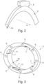
- Figure 2 shows an enlarged perspective view of an arc shaped locking element part 9 provided with the protrusion 8, which has, in axial direction A, a T-shaped cross-section.
- the arc shaped locking element part 9 has a slanting contact surface 10, with which the part 9 abuts a side of the groove 3 of the hose 2.
- Figure 3 shows a perspective view of the annular flange body 4.
- This flange body 4 has a uniform width w and is provided with four grooves 7 with T-shaped cross-section. The length of the grooves 7 is smaller than the width w, such that a stop 11 is provided against which a T-shaped protrusion 8 can rest. This stop 11 allows for an axial force to be exerted from the annular flange body 4 onto the hose 2, such that the hose end can be pressed sealingly against another flange.
- Figure 4 shows a cross-sectional view of the combination 1 of figure 1 .
- the flange is in assembled state such that the annular locking element is coupled to and arranged concentrically within the annular flange body 4.
- the diameter D c of the central hose opening 5 is larger than the outer diameter D h of the hose 2, while the inner diameter of the annular locking element corresponds to the diameter D g of the groove 3.
Landscapes
- Engineering & Computer Science (AREA)
- General Engineering & Computer Science (AREA)
- Mechanical Engineering (AREA)
- Joints That Cut Off Fluids, And Hose Joints (AREA)
- Flanged Joints, Insulating Joints, And Other Joints (AREA)
- Quick-Acting Or Multi-Walled Pipe Joints (AREA)
Claims (5)
- Flansch für einen Schlauch (2), wobei der Flansch umfasst:- einen ringförmigen Flanschkörper (4), der eine mittlere Schlauchöffnung (5) aufweist,- ein ringförmiges Klemmelement zum Einklemmen des ringförmigen Flanschkörpers (4) in einer umlaufenden Nut (3) eines Schlauchs (2), wobei das ringförmige Klemmelement aus wenigstens zwei im Allgemeinen bogenförmigen Klemmelementteilen (9) besteht, wobei das ringförmige Klemmelement konzentrisch in der mittleren Schlauchöffnung (5) des ringförmigen Flanschkörpers (4) angeordnet ist, und- Kupplungen für jeden der wenigstens zwei im Allgemeinen bogenförmigen Klemmelementteile (9), wobei jede Kupplung einen ersten Kupplungsteil, der auf dem ringförmigen Flanschkörper (4) angeordnet ist, und einen zweiten Kupplungsteil, der auf dem entsprechenden bogenförmigen Klemmelementteil (9) angeordnet ist, aufweist, wobei sich der erste Kupplungsteil mit dem zweiten Kupplungsteil koppelt, um zu gewährleisten, dass sich der ringförmige Flanschkörper (4) und das ringförmige Klemmelement nicht mehr relativ zueinander verschieben können, dadurch gekennzeichnet, dassder erste Kupplungsteil eine Nut (7) ist, die sich in einer axialen Richtung (A) von der ersten Endfläche des ringförmigen Flanschkörpers (4) erstreckt, wobei die Länge der Nut (7) kleiner als eine Dicke (w) des ringförmigen Flanschkörpers (4) ist und wobei der zweite Kupplungsteil ein Vorsprung (8) ist, der auf der radial äußeren Fläche des entsprechenden Klemmelementteils (9) angeordnet ist, wobei der Vorsprung (8) in der axialen Richtung (A) einen Querschnitt aufweist, der dem Querschnitt der Nut (7) entspricht.
- Flansch nach Anspruch 1, wobei der Querschnitt des Vorsprungs (8) und der Querschnitt der Nut (7) T-förmig sind.
- Flansch nach einem der vorhergehenden Ansprüche, wobei ein Außendurchmesser des ringförmigen Klemmelements einem Durchmesser (Dc) der mittleren Schlauchöffnung (5) entspricht.
- Flansch nach einem der vorhergehenden Ansprüche, wobei der ringförmige Flanschkörper (4) eine Anzahl von sich axial erstreckenden Durchgangslöchern (6) aufweist, die gleichmäßig entlang einem Umfang des ringförmigen Flanschkörpers (4) positioniert sind.
- Kombination aus einem Flansch nach einem der vorhergehenden Ansprüche und einem Schlauch (2), der einen Außendurchmesser (Dh) aufweist, der kleiner als der Durchmesser der mittleren Schlauchöffnung (Dc) und größer als der Innendurchmesser des ringförmigen Klemmelements ist, wobei der Schlauch (2) an einem Ende die umlaufende Nut (3) aufweist, in der das ringförmige Klemmelement wenigstens zum Teil aufgenommen ist.
Applications Claiming Priority (2)
| Application Number | Priority Date | Filing Date | Title |
|---|---|---|---|
| GB1901012.3A GB2580692B (en) | 2019-01-25 | 2019-01-25 | Flange for a hose |
| PCT/EP2020/050696 WO2020151981A1 (en) | 2019-01-25 | 2020-01-13 | Flange for a hose |
Publications (2)
| Publication Number | Publication Date |
|---|---|
| EP3914845A1 EP3914845A1 (de) | 2021-12-01 |
| EP3914845B1 true EP3914845B1 (de) | 2023-12-27 |
Family
ID=65656018
Family Applications (1)
| Application Number | Title | Priority Date | Filing Date |
|---|---|---|---|
| EP20702074.4A Active EP3914845B1 (de) | 2019-01-25 | 2020-01-13 | Flansch für einen schlauch |
Country Status (5)
| Country | Link |
|---|---|
| US (1) | US12049970B2 (de) |
| EP (1) | EP3914845B1 (de) |
| CN (1) | CN113614432B (de) |
| GB (1) | GB2580692B (de) |
| WO (1) | WO2020151981A1 (de) |
Families Citing this family (2)
| Publication number | Priority date | Publication date | Assignee | Title |
|---|---|---|---|---|
| US12449072B1 (en) * | 2024-07-10 | 2025-10-21 | Cosmoind Co., Ltd | Pipe connection device |
| CN119777749B (zh) * | 2025-01-03 | 2026-04-21 | 烟台泰悦流体科技有限公司 | 一种用于高压油田的压裂软管 |
Family Cites Families (15)
| Publication number | Priority date | Publication date | Assignee | Title |
|---|---|---|---|---|
| US2568414A (en) * | 1947-01-07 | 1951-09-18 | Ira A Russ | Pipe joint |
| US3085820A (en) * | 1958-07-21 | 1963-04-16 | Andrew A Pollia | Detachable pipe coupling including a detachable flange |
| GB1350199A (en) * | 1970-11-10 | 1974-04-18 | Laity T | Engine exhaust pipe joints |
| US3934902A (en) * | 1973-12-18 | 1976-01-27 | Rca Corporation | Connector for a corrugated conduit |
| DE29518603U1 (de) * | 1995-11-24 | 1996-01-11 | BRUGG Rohrsysteme GmbH, 31515 Wunstorf | Flammlose Anschlußverbindung für Wellrohre |
| KR100269937B1 (ko) * | 1998-07-04 | 2000-10-16 | 손화현 | 냉매파이프 연결구 |
| US6460901B2 (en) * | 2001-02-13 | 2002-10-08 | Alpha-Western Corporation | Split thread nut assembly |
| US6935153B2 (en) * | 2003-03-27 | 2005-08-30 | Andrew Corporation | Method and apparatus for flaring a tube |
| DE10355848A1 (de) | 2003-11-26 | 2005-07-21 | Abb Patent Gmbh | Flanschverbindung und Verfahren zu deren Herstellung |
| JP4851627B1 (ja) * | 2011-01-14 | 2012-01-11 | ゼンシン株式会社 | 金属製可撓管 |
| FR2976041B1 (fr) * | 2011-05-30 | 2014-07-25 | Ensival Moret France | Bride de raccordement d'une tuyauterie hydraulique ou pneumatique d'une machine industrielle |
| MX345431B (es) * | 2012-01-03 | 2017-01-31 | Micro Motion Inc | Método y aparato de retención de brida en un medidor de fluido. |
| CN204628863U (zh) | 2015-03-18 | 2015-09-09 | 董布和 | 一种管道活套法兰接头 |
| CN204829023U (zh) | 2015-07-25 | 2015-12-02 | 零八一电子集团四川华昌电子有限公司 | 新型充气型椭圆-矩形转换波导用气密封法兰 |
| CN106439306A (zh) | 2015-08-04 | 2017-02-22 | 中国科学院物理研究所 | 旋转法兰 |
-
2019
- 2019-01-25 GB GB1901012.3A patent/GB2580692B/en active Active
-
2020
- 2020-01-13 CN CN202080023535.4A patent/CN113614432B/zh active Active
- 2020-01-13 EP EP20702074.4A patent/EP3914845B1/de active Active
- 2020-01-13 US US17/425,700 patent/US12049970B2/en active Active
- 2020-01-13 WO PCT/EP2020/050696 patent/WO2020151981A1/en not_active Ceased
Also Published As
| Publication number | Publication date |
|---|---|
| EP3914845A1 (de) | 2021-12-01 |
| CN113614432B (zh) | 2023-08-22 |
| US20220163146A1 (en) | 2022-05-26 |
| GB201901012D0 (en) | 2019-03-13 |
| GB2580692A (en) | 2020-07-29 |
| GB2580692B (en) | 2022-09-28 |
| CN113614432A (zh) | 2021-11-05 |
| US12049970B2 (en) | 2024-07-30 |
| WO2020151981A1 (en) | 2020-07-30 |
Similar Documents
| Publication | Publication Date | Title |
|---|---|---|
| US9915385B2 (en) | Fitting with draw mechanism | |
| US6439617B1 (en) | Coupler for a pipe or hose section | |
| EP0937935B1 (de) | Rohrverbindung | |
| WO2001096774A1 (en) | Pipe coupling device | |
| EP3914845B1 (de) | Flansch für einen schlauch | |
| EP3460305B1 (de) | Rückhalteklemmring zum verbinden von zwei rohren und von rohren mit verbindungen | |
| US20160169432A1 (en) | Hydraulic cylinder joint and hydraulic cylinder pipe including same | |
| EP0727026B1 (de) | Rohrverbindung | |
| TWI437179B (zh) | 用於爪形軸環之總成,相對應的爪形軸環及管形接頭 | |
| CN109996985B (zh) | 密封组件 | |
| WO2001031243A2 (en) | Pipe fitting element, particularly for plastic pipes | |
| US7731240B2 (en) | Pipe coupling | |
| US5360238A (en) | Pipe couplings | |
| EP3732387B1 (de) | Einschränkende schlauchkupplung | |
| EP0455464A2 (de) | Rohrkupplung | |
| CA1179393A (en) | Quick-connect coupling for thin-walled pipes | |
| HK40011243A (en) | Seal assembly | |
| WO2001090627A1 (en) | Pipe coupling |
Legal Events
| Date | Code | Title | Description |
|---|---|---|---|
| STAA | Information on the status of an ep patent application or granted ep patent |
Free format text: STATUS: UNKNOWN |
|
| STAA | Information on the status of an ep patent application or granted ep patent |
Free format text: STATUS: THE INTERNATIONAL PUBLICATION HAS BEEN MADE |
|
| PUAI | Public reference made under article 153(3) epc to a published international application that has entered the european phase |
Free format text: ORIGINAL CODE: 0009012 |
|
| STAA | Information on the status of an ep patent application or granted ep patent |
Free format text: STATUS: REQUEST FOR EXAMINATION WAS MADE |
|
| 17P | Request for examination filed |
Effective date: 20210707 |
|
| AK | Designated contracting states |
Kind code of ref document: A1 Designated state(s): AL AT BE BG CH CY CZ DE DK EE ES FI FR GB GR HR HU IE IS IT LI LT LU LV MC MK MT NL NO PL PT RO RS SE SI SK SM TR |
|
| DAV | Request for validation of the european patent (deleted) | ||
| DAX | Request for extension of the european patent (deleted) | ||
| RAP1 | Party data changed (applicant data changed or rights of an application transferred) |
Owner name: DANFOSS POWER SOLUTIONS II TECHNOLOGY A/S |
|
| GRAP | Despatch of communication of intention to grant a patent |
Free format text: ORIGINAL CODE: EPIDOSNIGR1 |
|
| STAA | Information on the status of an ep patent application or granted ep patent |
Free format text: STATUS: GRANT OF PATENT IS INTENDED |
|
| RIC1 | Information provided on ipc code assigned before grant |
Ipc: F16L 33/28 20060101ALI20230711BHEP Ipc: F16L 23/028 20060101ALI20230711BHEP Ipc: F16L 19/02 20060101ALI20230711BHEP Ipc: F16L 33/26 20060101ALI20230711BHEP Ipc: F16L 23/00 20060101AFI20230711BHEP |
|
| P01 | Opt-out of the competence of the unified patent court (upc) registered |
Effective date: 20230713 |
|
| INTG | Intention to grant announced |
Effective date: 20230731 |
|
| GRAS | Grant fee paid |
Free format text: ORIGINAL CODE: EPIDOSNIGR3 |
|
| GRAA | (expected) grant |
Free format text: ORIGINAL CODE: 0009210 |
|
| STAA | Information on the status of an ep patent application or granted ep patent |
Free format text: STATUS: THE PATENT HAS BEEN GRANTED |
|
| RAP1 | Party data changed (applicant data changed or rights of an application transferred) |
Owner name: DANFOSS A/S |
|
| AK | Designated contracting states |
Kind code of ref document: B1 Designated state(s): AL AT BE BG CH CY CZ DE DK EE ES FI FR GB GR HR HU IE IS IT LI LT LU LV MC MK MT NL NO PL PT RO RS SE SI SK SM TR |
|
| REG | Reference to a national code |
Ref country code: GB Ref legal event code: FG4D |
|
| REG | Reference to a national code |
Ref country code: CH Ref legal event code: EP |
|
| REG | Reference to a national code |
Ref country code: DE Ref legal event code: R096 Ref document number: 602020023353 Country of ref document: DE |
|
| REG | Reference to a national code |
Ref country code: IE Ref legal event code: FG4D |
|
| PG25 | Lapsed in a contracting state [announced via postgrant information from national office to epo] |
Ref country code: GR Free format text: LAPSE BECAUSE OF FAILURE TO SUBMIT A TRANSLATION OF THE DESCRIPTION OR TO PAY THE FEE WITHIN THE PRESCRIBED TIME-LIMIT Effective date: 20240328 |
|
| REG | Reference to a national code |
Ref country code: LT Ref legal event code: MG9D |
|
| PG25 | Lapsed in a contracting state [announced via postgrant information from national office to epo] |
Ref country code: LT Free format text: LAPSE BECAUSE OF FAILURE TO SUBMIT A TRANSLATION OF THE DESCRIPTION OR TO PAY THE FEE WITHIN THE PRESCRIBED TIME-LIMIT Effective date: 20231227 |
|
| PG25 | Lapsed in a contracting state [announced via postgrant information from national office to epo] |
Ref country code: ES Free format text: LAPSE BECAUSE OF FAILURE TO SUBMIT A TRANSLATION OF THE DESCRIPTION OR TO PAY THE FEE WITHIN THE PRESCRIBED TIME-LIMIT Effective date: 20231227 |
|
| PG25 | Lapsed in a contracting state [announced via postgrant information from national office to epo] |
Ref country code: LT Free format text: LAPSE BECAUSE OF FAILURE TO SUBMIT A TRANSLATION OF THE DESCRIPTION OR TO PAY THE FEE WITHIN THE PRESCRIBED TIME-LIMIT Effective date: 20231227 Ref country code: GR Free format text: LAPSE BECAUSE OF FAILURE TO SUBMIT A TRANSLATION OF THE DESCRIPTION OR TO PAY THE FEE WITHIN THE PRESCRIBED TIME-LIMIT Effective date: 20240328 Ref country code: FI Free format text: LAPSE BECAUSE OF FAILURE TO SUBMIT A TRANSLATION OF THE DESCRIPTION OR TO PAY THE FEE WITHIN THE PRESCRIBED TIME-LIMIT Effective date: 20231227 Ref country code: ES Free format text: LAPSE BECAUSE OF FAILURE TO SUBMIT A TRANSLATION OF THE DESCRIPTION OR TO PAY THE FEE WITHIN THE PRESCRIBED TIME-LIMIT Effective date: 20231227 Ref country code: BG Free format text: LAPSE BECAUSE OF FAILURE TO SUBMIT A TRANSLATION OF THE DESCRIPTION OR TO PAY THE FEE WITHIN THE PRESCRIBED TIME-LIMIT Effective date: 20240327 |
|
| REG | Reference to a national code |
Ref country code: NL Ref legal event code: MP Effective date: 20231227 |
|
| REG | Reference to a national code |
Ref country code: AT Ref legal event code: MK05 Ref document number: 1644819 Country of ref document: AT Kind code of ref document: T Effective date: 20231227 |
|
| PG25 | Lapsed in a contracting state [announced via postgrant information from national office to epo] |
Ref country code: NL Free format text: LAPSE BECAUSE OF FAILURE TO SUBMIT A TRANSLATION OF THE DESCRIPTION OR TO PAY THE FEE WITHIN THE PRESCRIBED TIME-LIMIT Effective date: 20231227 |
|
| PG25 | Lapsed in a contracting state [announced via postgrant information from national office to epo] |
Ref country code: SE Free format text: LAPSE BECAUSE OF FAILURE TO SUBMIT A TRANSLATION OF THE DESCRIPTION OR TO PAY THE FEE WITHIN THE PRESCRIBED TIME-LIMIT Effective date: 20231227 Ref country code: RS Free format text: LAPSE BECAUSE OF FAILURE TO SUBMIT A TRANSLATION OF THE DESCRIPTION OR TO PAY THE FEE WITHIN THE PRESCRIBED TIME-LIMIT Effective date: 20231227 Ref country code: NO Free format text: LAPSE BECAUSE OF FAILURE TO SUBMIT A TRANSLATION OF THE DESCRIPTION OR TO PAY THE FEE WITHIN THE PRESCRIBED TIME-LIMIT Effective date: 20240327 Ref country code: NL Free format text: LAPSE BECAUSE OF FAILURE TO SUBMIT A TRANSLATION OF THE DESCRIPTION OR TO PAY THE FEE WITHIN THE PRESCRIBED TIME-LIMIT Effective date: 20231227 Ref country code: LV Free format text: LAPSE BECAUSE OF FAILURE TO SUBMIT A TRANSLATION OF THE DESCRIPTION OR TO PAY THE FEE WITHIN THE PRESCRIBED TIME-LIMIT Effective date: 20231227 Ref country code: HR Free format text: LAPSE BECAUSE OF FAILURE TO SUBMIT A TRANSLATION OF THE DESCRIPTION OR TO PAY THE FEE WITHIN THE PRESCRIBED TIME-LIMIT Effective date: 20231227 |
|
| PG25 | Lapsed in a contracting state [announced via postgrant information from national office to epo] |
Ref country code: IS Free format text: LAPSE BECAUSE OF FAILURE TO SUBMIT A TRANSLATION OF THE DESCRIPTION OR TO PAY THE FEE WITHIN THE PRESCRIBED TIME-LIMIT Effective date: 20240427 |
|
| PG25 | Lapsed in a contracting state [announced via postgrant information from national office to epo] |
Ref country code: CZ Free format text: LAPSE BECAUSE OF FAILURE TO SUBMIT A TRANSLATION OF THE DESCRIPTION OR TO PAY THE FEE WITHIN THE PRESCRIBED TIME-LIMIT Effective date: 20231227 Ref country code: AT Free format text: LAPSE BECAUSE OF FAILURE TO SUBMIT A TRANSLATION OF THE DESCRIPTION OR TO PAY THE FEE WITHIN THE PRESCRIBED TIME-LIMIT Effective date: 20231227 |
|
| PG25 | Lapsed in a contracting state [announced via postgrant information from national office to epo] |
Ref country code: SK Free format text: LAPSE BECAUSE OF FAILURE TO SUBMIT A TRANSLATION OF THE DESCRIPTION OR TO PAY THE FEE WITHIN THE PRESCRIBED TIME-LIMIT Effective date: 20231227 |
|
| PG25 | Lapsed in a contracting state [announced via postgrant information from national office to epo] |
Ref country code: SM Free format text: LAPSE BECAUSE OF FAILURE TO SUBMIT A TRANSLATION OF THE DESCRIPTION OR TO PAY THE FEE WITHIN THE PRESCRIBED TIME-LIMIT Effective date: 20231227 Ref country code: SK Free format text: LAPSE BECAUSE OF FAILURE TO SUBMIT A TRANSLATION OF THE DESCRIPTION OR TO PAY THE FEE WITHIN THE PRESCRIBED TIME-LIMIT Effective date: 20231227 Ref country code: RO Free format text: LAPSE BECAUSE OF FAILURE TO SUBMIT A TRANSLATION OF THE DESCRIPTION OR TO PAY THE FEE WITHIN THE PRESCRIBED TIME-LIMIT Effective date: 20231227 Ref country code: IT Free format text: LAPSE BECAUSE OF FAILURE TO SUBMIT A TRANSLATION OF THE DESCRIPTION OR TO PAY THE FEE WITHIN THE PRESCRIBED TIME-LIMIT Effective date: 20231227 Ref country code: IS Free format text: LAPSE BECAUSE OF FAILURE TO SUBMIT A TRANSLATION OF THE DESCRIPTION OR TO PAY THE FEE WITHIN THE PRESCRIBED TIME-LIMIT Effective date: 20240427 Ref country code: EE Free format text: LAPSE BECAUSE OF FAILURE TO SUBMIT A TRANSLATION OF THE DESCRIPTION OR TO PAY THE FEE WITHIN THE PRESCRIBED TIME-LIMIT Effective date: 20231227 Ref country code: CZ Free format text: LAPSE BECAUSE OF FAILURE TO SUBMIT A TRANSLATION OF THE DESCRIPTION OR TO PAY THE FEE WITHIN THE PRESCRIBED TIME-LIMIT Effective date: 20231227 Ref country code: AT Free format text: LAPSE BECAUSE OF FAILURE TO SUBMIT A TRANSLATION OF THE DESCRIPTION OR TO PAY THE FEE WITHIN THE PRESCRIBED TIME-LIMIT Effective date: 20231227 |
|
| PG25 | Lapsed in a contracting state [announced via postgrant information from national office to epo] |
Ref country code: PT Free format text: LAPSE BECAUSE OF FAILURE TO SUBMIT A TRANSLATION OF THE DESCRIPTION OR TO PAY THE FEE WITHIN THE PRESCRIBED TIME-LIMIT Effective date: 20240429 Ref country code: PL Free format text: LAPSE BECAUSE OF FAILURE TO SUBMIT A TRANSLATION OF THE DESCRIPTION OR TO PAY THE FEE WITHIN THE PRESCRIBED TIME-LIMIT Effective date: 20231227 |
|
| PG25 | Lapsed in a contracting state [announced via postgrant information from national office to epo] |
Ref country code: PT Free format text: LAPSE BECAUSE OF FAILURE TO SUBMIT A TRANSLATION OF THE DESCRIPTION OR TO PAY THE FEE WITHIN THE PRESCRIBED TIME-LIMIT Effective date: 20240429 Ref country code: PL Free format text: LAPSE BECAUSE OF FAILURE TO SUBMIT A TRANSLATION OF THE DESCRIPTION OR TO PAY THE FEE WITHIN THE PRESCRIBED TIME-LIMIT Effective date: 20231227 |
|
| REG | Reference to a national code |
Ref country code: CH Ref legal event code: PL |
|
| PG25 | Lapsed in a contracting state [announced via postgrant information from national office to epo] |
Ref country code: LU Free format text: LAPSE BECAUSE OF NON-PAYMENT OF DUE FEES Effective date: 20240113 |
|
| PG25 | Lapsed in a contracting state [announced via postgrant information from national office to epo] |
Ref country code: LU Free format text: LAPSE BECAUSE OF NON-PAYMENT OF DUE FEES Effective date: 20240113 Ref country code: MC Free format text: LAPSE BECAUSE OF FAILURE TO SUBMIT A TRANSLATION OF THE DESCRIPTION OR TO PAY THE FEE WITHIN THE PRESCRIBED TIME-LIMIT Effective date: 20231227 |
|
| REG | Reference to a national code |
Ref country code: DE Ref legal event code: R097 Ref document number: 602020023353 Country of ref document: DE |
|
| PG25 | Lapsed in a contracting state [announced via postgrant information from national office to epo] |
Ref country code: DK Free format text: LAPSE BECAUSE OF FAILURE TO SUBMIT A TRANSLATION OF THE DESCRIPTION OR TO PAY THE FEE WITHIN THE PRESCRIBED TIME-LIMIT Effective date: 20231227 |
|
| PG25 | Lapsed in a contracting state [announced via postgrant information from national office to epo] |
Ref country code: BE Free format text: LAPSE BECAUSE OF NON-PAYMENT OF DUE FEES Effective date: 20240131 |
|
| PG25 | Lapsed in a contracting state [announced via postgrant information from national office to epo] |
Ref country code: CH Free format text: LAPSE BECAUSE OF NON-PAYMENT OF DUE FEES Effective date: 20240131 |
|
| PG25 | Lapsed in a contracting state [announced via postgrant information from national office to epo] |
Ref country code: DK Free format text: LAPSE BECAUSE OF FAILURE TO SUBMIT A TRANSLATION OF THE DESCRIPTION OR TO PAY THE FEE WITHIN THE PRESCRIBED TIME-LIMIT Effective date: 20231227 Ref country code: CH Free format text: LAPSE BECAUSE OF NON-PAYMENT OF DUE FEES Effective date: 20240131 Ref country code: BE Free format text: LAPSE BECAUSE OF NON-PAYMENT OF DUE FEES Effective date: 20240131 |
|
| PLBE | No opposition filed within time limit |
Free format text: ORIGINAL CODE: 0009261 |
|
| STAA | Information on the status of an ep patent application or granted ep patent |
Free format text: STATUS: NO OPPOSITION FILED WITHIN TIME LIMIT |
|
| REG | Reference to a national code |
Ref country code: BE Ref legal event code: MM Effective date: 20240131 |
|
| 26N | No opposition filed |
Effective date: 20240930 |
|
| PG25 | Lapsed in a contracting state [announced via postgrant information from national office to epo] |
Ref country code: IE Free format text: LAPSE BECAUSE OF NON-PAYMENT OF DUE FEES Effective date: 20240113 |
|
| PG25 | Lapsed in a contracting state [announced via postgrant information from national office to epo] |
Ref country code: IE Free format text: LAPSE BECAUSE OF NON-PAYMENT OF DUE FEES Effective date: 20240113 |
|
| PG25 | Lapsed in a contracting state [announced via postgrant information from national office to epo] |
Ref country code: SI Free format text: LAPSE BECAUSE OF FAILURE TO SUBMIT A TRANSLATION OF THE DESCRIPTION OR TO PAY THE FEE WITHIN THE PRESCRIBED TIME-LIMIT Effective date: 20231227 |
|
| PG25 | Lapsed in a contracting state [announced via postgrant information from national office to epo] |
Ref country code: CY Free format text: LAPSE BECAUSE OF FAILURE TO SUBMIT A TRANSLATION OF THE DESCRIPTION OR TO PAY THE FEE WITHIN THE PRESCRIBED TIME-LIMIT; INVALID AB INITIO Effective date: 20200113 |
|
| PG25 | Lapsed in a contracting state [announced via postgrant information from national office to epo] |
Ref country code: HU Free format text: LAPSE BECAUSE OF FAILURE TO SUBMIT A TRANSLATION OF THE DESCRIPTION OR TO PAY THE FEE WITHIN THE PRESCRIBED TIME-LIMIT; INVALID AB INITIO Effective date: 20200113 |
|
| PG25 | Lapsed in a contracting state [announced via postgrant information from national office to epo] |
Ref country code: TR Free format text: LAPSE BECAUSE OF FAILURE TO SUBMIT A TRANSLATION OF THE DESCRIPTION OR TO PAY THE FEE WITHIN THE PRESCRIBED TIME-LIMIT Effective date: 20231227 |
|
| PGFP | Annual fee paid to national office [announced via postgrant information from national office to epo] |
Ref country code: GB Payment date: 20251204 Year of fee payment: 7 |
|
| PGFP | Annual fee paid to national office [announced via postgrant information from national office to epo] |
Ref country code: FR Payment date: 20251208 Year of fee payment: 7 |
|
| PGFP | Annual fee paid to national office [announced via postgrant information from national office to epo] |
Ref country code: DE Payment date: 20251203 Year of fee payment: 7 |