EP3914775B1 - Automated road sweeper and road cleaning method using said road sweeper - Google Patents
Automated road sweeper and road cleaning method using said road sweeper Download PDFInfo
- Publication number
- EP3914775B1 EP3914775B1 EP19836525.6A EP19836525A EP3914775B1 EP 3914775 B1 EP3914775 B1 EP 3914775B1 EP 19836525 A EP19836525 A EP 19836525A EP 3914775 B1 EP3914775 B1 EP 3914775B1
- Authority
- EP
- European Patent Office
- Prior art keywords
- cleaning
- debris
- sweeper
- road
- road surface
- Prior art date
- Legal status (The legal status is an assumption and is not a legal conclusion. Google has not performed a legal analysis and makes no representation as to the accuracy of the status listed.)
- Active
Links
Images
Classifications
-
- E—FIXED CONSTRUCTIONS
- E01—CONSTRUCTION OF ROADS, RAILWAYS, OR BRIDGES
- E01H—STREET CLEANING; CLEANING OF PERMANENT WAYS; CLEANING BEACHES; DISPERSING OR PREVENTING FOG IN GENERAL CLEANING STREET OR RAILWAY FURNITURE OR TUNNEL WALLS
- E01H1/00—Removing undesirable matter from roads or like surfaces, with or without moistening of the surface
- E01H1/02—Brushing apparatus, e.g. with auxiliary instruments for mechanically loosening dirt
- E01H1/04—Brushing apparatus, e.g. with auxiliary instruments for mechanically loosening dirt taking- up the sweepings, e.g. for collecting, for loading
-
- E—FIXED CONSTRUCTIONS
- E01—CONSTRUCTION OF ROADS, RAILWAYS, OR BRIDGES
- E01H—STREET CLEANING; CLEANING OF PERMANENT WAYS; CLEANING BEACHES; DISPERSING OR PREVENTING FOG IN GENERAL CLEANING STREET OR RAILWAY FURNITURE OR TUNNEL WALLS
- E01H1/00—Removing undesirable matter from roads or like surfaces, with or without moistening of the surface
-
- A—HUMAN NECESSITIES
- A46—BRUSHWARE
- A46B—BRUSHES
- A46B13/00—Brushes with driven brush bodies or carriers
- A46B13/008—Disc-shaped brush bodies
-
- A—HUMAN NECESSITIES
- A46—BRUSHWARE
- A46B—BRUSHES
- A46B13/00—Brushes with driven brush bodies or carriers
- A46B13/02—Brushes with driven brush bodies or carriers power-driven carriers
-
- A—HUMAN NECESSITIES
- A46—BRUSHWARE
- A46B—BRUSHES
- A46B15/00—Other brushes; Brushes with additional arrangements
- A46B15/0002—Arrangements for enhancing monitoring or controlling the brushing process
- A46B15/0004—Arrangements for enhancing monitoring or controlling the brushing process with a controlling means
-
- E—FIXED CONSTRUCTIONS
- E01—CONSTRUCTION OF ROADS, RAILWAYS, OR BRIDGES
- E01H—STREET CLEANING; CLEANING OF PERMANENT WAYS; CLEANING BEACHES; DISPERSING OR PREVENTING FOG IN GENERAL CLEANING STREET OR RAILWAY FURNITURE OR TUNNEL WALLS
- E01H1/00—Removing undesirable matter from roads or like surfaces, with or without moistening of the surface
- E01H1/02—Brushing apparatus, e.g. with auxiliary instruments for mechanically loosening dirt
- E01H1/05—Brushing apparatus, e.g. with auxiliary instruments for mechanically loosening dirt with driven brushes
- E01H1/053—Brushing apparatus, e.g. with auxiliary instruments for mechanically loosening dirt with driven brushes having vertical axes
-
- E—FIXED CONSTRUCTIONS
- E01—CONSTRUCTION OF ROADS, RAILWAYS, OR BRIDGES
- E01H—STREET CLEANING; CLEANING OF PERMANENT WAYS; CLEANING BEACHES; DISPERSING OR PREVENTING FOG IN GENERAL CLEANING STREET OR RAILWAY FURNITURE OR TUNNEL WALLS
- E01H1/00—Removing undesirable matter from roads or like surfaces, with or without moistening of the surface
- E01H1/08—Pneumatically dislodging or taking-up undesirable matter or small objects; Drying by heat only or by streams of gas; Cleaning by projecting abrasive particles
-
- E—FIXED CONSTRUCTIONS
- E01—CONSTRUCTION OF ROADS, RAILWAYS, OR BRIDGES
- E01H—STREET CLEANING; CLEANING OF PERMANENT WAYS; CLEANING BEACHES; DISPERSING OR PREVENTING FOG IN GENERAL CLEANING STREET OR RAILWAY FURNITURE OR TUNNEL WALLS
- E01H1/00—Removing undesirable matter from roads or like surfaces, with or without moistening of the surface
- E01H1/10—Hydraulically loosening or dislodging undesirable matter; Raking or scraping apparatus ; Removing liquids or semi-liquids e.g., absorbing water, sliding-off mud
-
- G—PHYSICS
- G06—COMPUTING OR CALCULATING; COUNTING
- G06V—IMAGE OR VIDEO RECOGNITION OR UNDERSTANDING
- G06V10/00—Arrangements for image or video recognition or understanding
- G06V10/70—Arrangements for image or video recognition or understanding using pattern recognition or machine learning
- G06V10/74—Image or video pattern matching; Proximity measures in feature spaces
- G06V10/75—Organisation of the matching processes, e.g. simultaneous or sequential comparisons of image or video features; Coarse-fine approaches, e.g. multi-scale approaches; using context analysis; Selection of dictionaries
- G06V10/751—Comparing pixel values or logical combinations thereof, or feature values having positional relevance, e.g. template matching
-
- G—PHYSICS
- G06—COMPUTING OR CALCULATING; COUNTING
- G06V—IMAGE OR VIDEO RECOGNITION OR UNDERSTANDING
- G06V20/00—Scenes; Scene-specific elements
- G06V20/50—Context or environment of the image
- G06V20/56—Context or environment of the image exterior to a vehicle by using sensors mounted on the vehicle
- G06V20/588—Recognition of the road, e.g. of lane markings; Recognition of the vehicle driving pattern in relation to the road
-
- A—HUMAN NECESSITIES
- A46—BRUSHWARE
- A46B—BRUSHES
- A46B2200/00—Brushes characterized by their functions, uses or applications
- A46B2200/30—Brushes for cleaning or polishing
- A46B2200/3066—Brush specifically designed for use with street cleaning machinery
-
- E—FIXED CONSTRUCTIONS
- E01—CONSTRUCTION OF ROADS, RAILWAYS, OR BRIDGES
- E01H—STREET CLEANING; CLEANING OF PERMANENT WAYS; CLEANING BEACHES; DISPERSING OR PREVENTING FOG IN GENERAL CLEANING STREET OR RAILWAY FURNITURE OR TUNNEL WALLS
- E01H1/00—Removing undesirable matter from roads or like surfaces, with or without moistening of the surface
- E01H1/08—Pneumatically dislodging or taking-up undesirable matter or small objects; Drying by heat only or by streams of gas; Cleaning by projecting abrasive particles
- E01H1/0827—Dislodging by suction; Mechanical dislodging-cleaning apparatus with independent or dependent exhaust, e.g. dislodging-sweeping machines with independent suction nozzles ; Mechanical loosening devices working under vacuum
- E01H1/0854—Apparatus in which the mechanically dislodged dirt is partially sucked-off, e.g. dislodging- sweeping apparatus with dirt collector in brush housing or dirt container
-
- E—FIXED CONSTRUCTIONS
- E01—CONSTRUCTION OF ROADS, RAILWAYS, OR BRIDGES
- E01H—STREET CLEANING; CLEANING OF PERMANENT WAYS; CLEANING BEACHES; DISPERSING OR PREVENTING FOG IN GENERAL CLEANING STREET OR RAILWAY FURNITURE OR TUNNEL WALLS
- E01H1/00—Removing undesirable matter from roads or like surfaces, with or without moistening of the surface
- E01H1/10—Hydraulically loosening or dislodging undesirable matter; Raking or scraping apparatus ; Removing liquids or semi-liquids e.g., absorbing water, sliding-off mud
- E01H1/101—Hydraulic loosening or dislodging, combined or not with mechanical loosening or dislodging, e.g. road washing machines with brushes or wipers
Definitions
- the present invention relates to an automated road sweeper and road cleaning method of said road sweeper of the type specified in the preamble of the first claim.
- the present invention relates to a motorized sweeper that can be driven by at least one operator and is suitable for cleaning the road base of dirt or debris, such as gravel, which may obstruct or, in any case, interfere with the circulation path of vehicles on at least one section of road.
- dirt or debris such as gravel
- a sweeper machine generally comprises a motorized vehicle, i.e. equipped with a motor suitable for making the vehicle itself autonomously mobile, a plurality of brushes emerging from the vehicle and intended for direct contact with the ground, a waste container, and a conveyor capable of sending the waste collected by the brushes into the latter container.
- an auxiliary tank can be set up next to the waste container and the conveyor for containing water to be distributed on the ground in order to dampen it before removing waste.
- Some sweeper machines can also proceed to cleaning the road surface or the common area by sprinkling them with abundant water.
- specially equipped vehicles are used with a front bar, on which washing nozzles are fitted; a large water tank; and a pumping unit that sends water to the above-mentioned nozzles.
- road surfaces do not all have the same conformation, but they can have surfaces that include a plurality of materials or, even, a plurality of portions separated from each other.
- the cleaning means used are not suitable for all types of roads and may have effects that are contrary to the functions for which they are intended. For example, incorrect cleaning or using incorrect tools can lead to the deposit of waste material inside the cracks that separate the cobblestones.
- the operator obtains the variation by operating a series of commands, knobs, and joysticks in the cab and must, simultaneously, drive the vehicle, identify the material on the ground, look at the road, check the other vehicles, avoid pedestrians and any obstacles, even sudden ones, and periodically check the rear video camera to see if the sweeper is collecting waste well.
- the technical task underlying the present invention is to devise an automated road sweeper and road cleaning method of said road sweeper, which is capable of substantially obviating at least some of the above-mentioned drawbacks.
- one important purpose of the invention is to obtain a road sweeper that is able to recognise the type of road surface on which it is carrying out the cleaning steps.
- Another important purpose of the invention is to create a road sweeper that is able to operate the cleaning means in a selective manner according to the type and density of debris on the road.
- an additional purpose of the invention is to create a sweeper that has lower energy consumption than the sweepers present in the current state of the art.
- the technical purpose and specified aims are achieved by an automated road sweeper as claimed in the appended claim 1 and by the road cleaning method as claimed in the appended claim 6.
- the measures, values, shapes, and geometric references when associated with words like “about” or other similar terms such as “approximately” or “substantially”, are to be understood as except for measurement errors or inaccuracies owing to production and/or manufacturing errors and, above all, except for a slight divergence from the value, measure, shape, or geometric reference with which it is associated.
- said terms, if associated with a value preferably indicate a divergence of not more than 10% of said value.
- the number 1 globally denotes the automated road sweeper according to the invention.
- the sweeper 1 is preferably a motorized means suitable for allowing the cleaning of a road surface 10.
- the road surface 10 is preferably defined by the flooring of any common or public area and can, for example, comprise a plurality of different materials that may also be configured in different ways.
- the road surface 10 may comprise asphalt or tar or similar paving materials, including those used for indoor structures, or it may also comprise pebbles, of which the classic cobblestone is a typical example, and have an irregular shape in which escape routes are also provided.
- road surface 10 can be broadly understood as the flooring of a building, and the sweeper 1 itself can be a small machine suitable for cleaning the floors of closed rooms.
- the road surface 10 can therefore comprise a plurality of types of debris 11.
- the debris 11 comprises, for example, dirt that is commonly deposited on road surfaces 10, or may be waste deposited on the surface 10, or may be damaged portions of the road surface 10.
- debris 11a means one or more types of debris 11 that can be removed or cleaned with the help of the same cleaning device.
- each of the grains of sand or gravel is included within a specific type of debris 11a, just as broken glass, metal, or solid polymer parts, are also part of the same specific type of debris 11a.
- the sweeper 1 is preferably largely known in the current state of the art and is a machine suitable for allowing the removal or cleaning of debris 11 from the road surface 10.
- the sweeper 1 comprises means of transport 2 and at least one cleaning member 3.
- the means of transport 2 are suitable for allowing the sweeper 1 to travel on the road surface 10. Normally, the sweeper 1 travels by the means of transport 2 on a road surface 10 comprising debris 11. In turn, the debris 11 may comprise one or more specific types of debris 11a.
- the means of transport 2 therefore comprise the transport devices such as the wheels or tracks and the motor and driver's compartment.
- the term means of transport 2 means everything that allows an operator to move the sweeper 1 on the road surface 10.
- the cleaning members 3 are, on the other hand, suitable for cleaning the road surface 10.
- many different cleaning members 3 are known, which have different conformations in order to allow the removal of specific different debris 11a, or even just the cleaning of the road surface 10.
- the more than one cleaning device 3 are arranged at fixed points located on different portions of the sweeper 1.
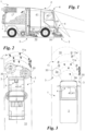
- cleaning members 3 can be provided on the front or side portion, or even on the rear portion, of the sweeper 1 and as, for example, shown in Fig. 1 and Fig. 3 .
- the cleaning members 3 are preferably tools that define a machining capacity and, therefore, essentially define a cleaning area 3a.
- the cleaning area 3a is preferably the area underneath the individual brush or, if the cleaning member 3 is of a different kind, the area underneath the cleaning tool.
- the cleaning area 3a should be considered, more broadly, as the area that the cleaning members 3 can describe when travelling.
- the cleaning area 3a is essentially the space defined by the cleaning members 3 along the travelling trajectory of the sweeper 1.
- the various cleaning members 3 may comprise brushes, or a bar comprising washing nozzles, or both.
- suction means suitable for removing debris 11 by creating a vacuum.
- Each of the cleaning members 3 can in fact include one or more cleaning heads 30.
- the cleaning heads 30 are preferably the ends of each cleaning member 3 that are suitable for interacting with the road surface 10 and, therefore, they can correspond respectively to the brushes or to the washing bar or to the suction means described above.
- each of the cleaning heads 30 is preferably suitable for cleaning a specific type of debris 11a, or it may be necessary to combine the different cleaning heads 30 for removing specific types of debris 11a.
- the sweeper 1 is essentially, preferably, a motorized vehicle, i.e. equipped with motors, including electric ones, suitable for making the vehicle itself autonomously mobile, a plurality of brushes, or other similar tools, emerging from the vehicle and intended for direct contact with the ground, a waste container and a conveyor capable of sending the waste collected by the brushes into the latter.
- a motorized vehicle i.e. equipped with motors, including electric ones, suitable for making the vehicle itself autonomously mobile, a plurality of brushes, or other similar tools, emerging from the vehicle and intended for direct contact with the ground, a waste container and a conveyor capable of sending the waste collected by the brushes into the latter.
- the sweeper 1 comprises, in addition to what is commonly present, selection means 4.
- the selection means 4 are operatively connected to the cleaning members 3. Therefore, the sweeper may, preferably, comprise electronic, or even mechanical or mechatronic, connections between the cleaning members 3 and the selection means 4 so that the latter can alter the behaviour of the cleaning means 3.
- the selection means 4 can perform a plurality of functions.
- the sweeper 1 comprises a plurality of cleaning members 3 positioned at fixed points of different portions of the sweeper 1, the selection means 4 being suitable for scanning the road surface 10.
- the selection means 4 should be suitable for scanning at least part of the road surface 10 and not necessarily the whole road surface 10.
- the selection means 4 locate the debris 11 so as to select and operate only the cleaning members 3 the cleaning area 3a of which covers the debris 11 during the movement of the sweeper 1.
- the selection means 4 are essentially suitable for defining target elements that condition the operation of the cleaning members 3.
- each of the cleaning members 3 comprises a plurality of cleaning heads 30, or alternatively to what is indicated, if the sweeper 1 includes, for example, a single cleaning member 3 comprising a plurality of cleaning heads 30, the selection means 4 preferably identify the type of debris 11 and select the cleaning head 30 corresponding to the specific type of debris 11a.
- the selection means 4 comprise optical means 40.
- the optical means 40 are suitable for recording at least one frame of the road surface 10.
- the term frame means a specific image or an ideal structure that represents the scanned environment or a sequence of elements.
- the optical means 40 comprise at least one video camera.
- the optical means 40 can, therefore, comprise only one video camera.
- the optical means 40 comprise a plurality of video cameras suitable for reconstructing the three-dimensional image of the road surface. These video cameras can then be offset from each other along a direction perpendicular to the ground, as in Fig. 1 , or along a direction parallel to the ground, as in Fig. 2 .
- the video camera(s) can be positioned and oriented differently.
- the selection means 4 are oriented integrally with the direction of movement given by the means of transport 2.
- the video camera frames the road surface 10 along the direction of travel. However, if several cameras are present, all of them can be oriented along the same direction of travel.
- the selection means 4 can also be oriented in the opposite direction to the direction of travel, as in Fig. 3 , or even to the sides.
- the sweeper 1 may comprise one or more feed-back video cameras suitable for checking that the sweeper 1 has been operating correctly and, therefore, preferably oriented contrary to the direction of travel given by the means of transport 2.
- the selection means 4 may further comprise a processor 41.
- the processor 41 is preferably an electronic component, e.g. comprising an electronic card, suitable for receiving images from the optical means 40 and for enabling the control or command of the cleaning means 3 based on the information obtained.
- the processor 41 is, preferably, in fact operatively connected to the optical means 40 and to the cleaning member or members 3. In addition, if there are several cleaning heads 30 on each cleaning member 3, the processor 41 is operatively connected to each cleaning head 30.
- the processor 41 therefore, preferably stores frames from the optical means 40 and selects and operates the proper cleaning member 3 or cleaning head 30.
- the processor 41 may also comprise a database of comparison images representing a plurality of different specific types of debris 11a.
- This database can be constructed on the basis of images acquired by the optical means 40, or, preferably, also includes external images.
- the processor 41 may comprise storage media that can be externally accessed via physical or even wireless connections.
- the processor 41 preferably compares the frame(s) captured by the optical means 40 with the comparison images in such a way as to select the cleaning head 30 corresponding to the specific detritus 10a identified.
- the processor 41 can also take a series of successive frames in such a way as to allow the processing of a preferred trajectory along which the cleaning members 3 travel or, if it is connected to part of the command means of the means of transport 2, to command the sweeper 1 itself along a trajectory that is defined based on the images.
- the processor 41 can also be operatively connected to the common command panel of the sweeper 1 and can operate the cleaning means 3 through this.
- the processor 41 processes the information and sends appropriate electrical command signals to the mechatronic implementing members, which suitably vary the kinematics and spatial position of, for example, the front brush, the side brushes, the central roller, the suction/removal power, and the cleaning area 3a of these elements.
- the database of the processor 41 can allow the association of predetermined operating configurations, with the setting of various parameters.
- the processor 41 can be equipped with software suitable for identifying, in addition to the position, type, approximate weight, and volume of debris 11, its area position in relation to the speed of the travelling sweeper 1 as well.
- the implementing part of the system's electronic management card can also calculate, in relation to the area position of the debris 11, the times and methods for the cleaning members 3 to work, by activating, in an appropriate way, the different cleaning members 3 or cleaning heads 30, the relative rotation speed, and the pressure to the ground.
- the operating parameters of these mechanical components can be varied by sending, via the electronics, appropriate electrical command signals to the hydraulic control units, motors, and hydraulic pistons, through the management of the many solenoid valves, control units, and command distributors of the sweeper machine 1.
- the selection means 4 can also create a mounting kit adaptable to vehicles or sweepers 1 on which they are not originally installed.
- the processor it is preferably sufficient for the processor to provide the first connection means suitable for ensuring the power supply of the selection means 4 and second connection means to the command panel of the transport means 2 or the cleaning members 3, for example, to the hydraulic control unit to actuate or change the various movements appropriately.
- the selection means 4 may also comprise connections and sockets that allow the system to be open, adaptive, suitable for receiving and managing other equipment, complementary to the kit, such as a back-up rear view video camera for checking proper cleaning, a front laser scanner or a SLAM laser scanner that can enable the system to capture three-dimensional images of the road, debris 11, sidewalks, and any obstacles.
- a back-up rear view video camera for checking proper cleaning
- a front laser scanner or a SLAM laser scanner that can enable the system to capture three-dimensional images of the road, debris 11, sidewalks, and any obstacles.
- the sweeper 1 may also comprise a display, available in the cab or passenger compartment in which the operator usually sits, suitable for projecting, on the windscreen, the essential operating data of the machine and the path to be followed for the areas to be cleaned, for example as calculated by the processor 41.
- the sweeper 1 can, therefore, provide that processor 41 connect to geolocation systems, such as GPS, to follow predetermined routes and precisely follow the edge of the pavement and the centre of the road. These routes can be managed, programmed remotely and in real time, thus leaving the operator with only the control and safety functions to manage.
- geolocation systems such as GPS
- the processor 41 can be managed, via the second connection means, if wireless, remotely and can enable the management of fleets of sweepers 1 from a single central location via a connection, for example, via the internet.
- the invention comprises a new road cleaning method.
- the method comprises at least the debris 11 location steps on the road surface 10, the selection of the cleaning members 3, the cleaning area 3a of which covers the debris 11 during the movement of the sweeper 1, and the operation of the cleaning members 3.
- At least one frame captured by the optical means 40 is processed by the processor 41.
- the processor 41 can construct a path or trajectory of travel for the cleaning members 3 based on the frames received from the optical means 40.
- the method may comprise, in addition to or alternatively to the previous steps, at least the steps of identifying the type of debris 11 and selecting the cleaning head 30 corresponding to the specific type of debris 11a.
- the processor 41 preferably compares at least one frame, or even more than one, with the comparison images present in its database in order to select the cleaning head 30, and possibly the correct processing machining parameters, corresponding to the specific type of detritus 10a identified.
- the method involves both the identification and the location of the debris 11, it first carries out the identification step and then the location step.
- the method is essentially a routine one that involves, in order, the detection, identification, and location of the debris 11 on the road surface 10.
- the method may also comprise a switching-off step for the cleaning members 3 when the cleaning area 3a is no longer covering the debris 11. In this way, it may consume less energy.
- the automated road sweeper 1 and its relative road cleaning method according to the invention achieve significant advantages.
- the sweeper 1 has a high efficiency in cleaning the road, lower energy consumption, and less wear of the brushes by adjusting the behaviour of the members of the vehicle according to the debris 11 present on the road surface 10, i.e. the material to be removed.
- the sweeper 1 allows you to improve the effectiveness of cleaning even in the presence of less experienced, distracted, or tired operators due to the monotony of street cleaning operations at very low speed.
- the conformation of the selection means 4 also allows the transfer of the experience and skills of an expert operator to this automated mechatronic system equipped with a two- to three-dimensional view of the road and the material to be removed, subsequently optimising the performance in relation to what is detected on the ground.
- sweeper Another advantage of the sweeper is that it automatically adapts to the various types of debris 11 to be removed from the road surface 10 during the collection and removal steps.
- the selection means 4 can be made as kits of several elements, modular and open, which can be installed on all road, industrial, and indoor sweeping machines.
Landscapes
- Engineering & Computer Science (AREA)
- Architecture (AREA)
- Civil Engineering (AREA)
- Structural Engineering (AREA)
- Theoretical Computer Science (AREA)
- Physics & Mathematics (AREA)
- General Physics & Mathematics (AREA)
- Multimedia (AREA)
- Computer Vision & Pattern Recognition (AREA)
- Artificial Intelligence (AREA)
- Health & Medical Sciences (AREA)
- Computing Systems (AREA)
- Databases & Information Systems (AREA)
- Evolutionary Computation (AREA)
- General Health & Medical Sciences (AREA)
- Medical Informatics (AREA)
- Software Systems (AREA)
- Cleaning Of Streets, Tracks, Or Beaches (AREA)
- Traffic Control Systems (AREA)
- Machines For Laying And Maintaining Railways (AREA)
- Control Of Position, Course, Altitude, Or Attitude Of Moving Bodies (AREA)
- Cleaning In General (AREA)
Description
- The present invention relates to an automated road sweeper and road cleaning method of said road sweeper of the type specified in the preamble of the first claim.
- In particular, the present invention relates to a motorized sweeper that can be driven by at least one operator and is suitable for cleaning the road base of dirt or debris, such as gravel, which may obstruct or, in any case, interfere with the circulation path of vehicles on at least one section of road.
- A similar sweeper is described in the patent application
WO-A-2016/198044 . - As is well known, a sweeper machine generally comprises a motorized vehicle, i.e. equipped with a motor suitable for making the vehicle itself autonomously mobile, a plurality of brushes emerging from the vehicle and intended for direct contact with the ground, a waste container, and a conveyor capable of sending the waste collected by the brushes into the latter container.
- In addition, an auxiliary tank can be set up next to the waste container and the conveyor for containing water to be distributed on the ground in order to dampen it before removing waste.
- Some sweeper machines can also proceed to cleaning the road surface or the common area by sprinkling them with abundant water.
- In these cases, specially equipped vehicles are used with a front bar, on which washing nozzles are fitted; a large water tank; and a pumping unit that sends water to the above-mentioned nozzles.
- The prior art described comprises several significant drawbacks.
- In particular, road surfaces do not all have the same conformation, but they can have surfaces that include a plurality of materials or, even, a plurality of portions separated from each other.
- In addition to roads made of common material, such as asphalt or tar, at present, there are stony or cobblestone roads, especially within the historical centre of Italian towns, which are, therefore, very irregular.
- Therefore, the cleaning means used are not suitable for all types of roads and may have effects that are contrary to the functions for which they are intended. For example, incorrect cleaning or using incorrect tools can lead to the deposit of waste material inside the cracks that separate the cobblestones.
- In addition, roads may not be completely covered with waste, but they may have empty areas where brushing is not necessary; however, the current state of the art sweepers are not able to operate the cleaning means effectively and when required. A further drawback, therefore, is the fact that the sweepers needlessly consume a large amount of energy to continuously feed the cleaning means.
- The only expedients that can be implemented involve direct action by the operator who, from the cab, sees the material in front of him, while the machine is moving forward, and can act on the hydraulic commands. This material in general is, as already mentioned, very variable and may comprise, in even more detail, undifferentiated debris, general, mixed dirt, material from construction sites, stones, plastic, cardboard, market waste, leaves, sand, bottles, pebbles of various sizes, gravel, or a mix of all of these. This material, as well as being mixed, has a nonhomogeneous distribution on the road or on the square. In this situation the operator, in order to optimise the work of the machine, must manually vary the different functions and mechanisms of the sweeper to adapt them to the type and ground distribution of the material in front of him.
- Currently, the operator obtains the variation by operating a series of commands, knobs, and joysticks in the cab and must, simultaneously, drive the vehicle, identify the material on the ground, look at the road, check the other vehicles, avoid pedestrians and any obstacles, even sudden ones, and periodically check the rear video camera to see if the sweeper is collecting waste well.
- In view of this considerable variability in manoeuvres and the attention that the operator must pay, s/he must have considerable experience in manually adapting the operation of the machine to the type of material to be removed. In these working conditions, the operator is then subjected to possible stresses or carelessness that may lead to accidents or the incorrect use of the road sweeper. These difficulties generally mean that the operator does not adapt the operation of the sweeper machine to the material on the ground, but maintains all the operating parameters of the brushes, the central roller, and the suction at maximum power and speed, even when not needed. This leads to the motor's consuming a lot of energy, the hydraulic oil's greatly heating up, and the brushes', and, generally, the machine's, being subjected to excessive wear.
- In this context, the technical task underlying the present invention is to devise an automated road sweeper and road cleaning method of said road sweeper, which is capable of substantially obviating at least some of the above-mentioned drawbacks. In the context of said technical task, one important purpose of the invention is to obtain a road sweeper that is able to recognise the type of road surface on which it is carrying out the cleaning steps.
- Another important purpose of the invention is to create a road sweeper that is able to operate the cleaning means in a selective manner according to the type and density of debris on the road.
- Therefore, an additional purpose of the invention is to create a sweeper that has lower energy consumption than the sweepers present in the current state of the art. The technical purpose and specified aims are achieved by an automated road sweeper as claimed in the appended claim 1 and by the road cleaning method as claimed in the appended claim 6.
- Preferred technical embodiments are described in the dependent claims.
- The features and advantages of the invention are clearly evident from the following detailed description of preferred embodiments thereof, with reference to the accompanying drawings, in which:
-
Fig. 1 shows a lateral view of an automated road sweeper according to the invention; -
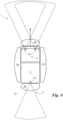
Fig. 2 shows a top view of an automated road sweeper according to the invention during the cleaning operations; and -
Fig. 3 is an example of an alternative arrangement of the selection means of an automated road sweeper according to the invention. - In this document, the measures, values, shapes, and geometric references (such as perpendicularity and parallelism), when associated with words like "about" or other similar terms such as "approximately" or "substantially", are to be understood as except for measurement errors or inaccuracies owing to production and/or manufacturing errors and, above all, except for a slight divergence from the value, measure, shape, or geometric reference with which it is associated. For example, said terms, if associated with a value, preferably indicate a divergence of not more than 10% of said value.
- In addition, where used, terms such as "first", "second", "upper", "lower", "main" and "secondary" do not necessarily refer to an order, a priority relationship or relative position, but may simply be used to more clearly distinguish different components from each other.
- The measurements and data presented herein are to be considered, unless otherwise indicated, as made in Standard International Atmospheres ICAO (ISO 2533: 1975).
- With reference to the Figures, the number 1 globally denotes the automated road sweeper according to the invention.
- The sweeper 1 is preferably a motorized means suitable for allowing the cleaning of a
road surface 10. - The
road surface 10 is preferably defined by the flooring of any common or public area and can, for example, comprise a plurality of different materials that may also be configured in different ways. - For example, the
road surface 10 may comprise asphalt or tar or similar paving materials, including those used for indoor structures, or it may also comprise pebbles, of which the classic cobblestone is a typical example, and have an irregular shape in which escape routes are also provided. - Even the
term road surface 10 can be broadly understood as the flooring of a building, and the sweeper 1 itself can be a small machine suitable for cleaning the floors of closed rooms. - The
road surface 10 can therefore comprise a plurality of types ofdebris 11. - The
debris 11 comprises, for example, dirt that is commonly deposited onroad surfaces 10, or may be waste deposited on thesurface 10, or may be damaged portions of theroad surface 10. - Therefore, different types of debris can be identified among the
debris 11. Each of the different types ofdebris 11 is, therefore, aspecific debris 11a. - The
specific term debris 11a means one or more types ofdebris 11 that can be removed or cleaned with the help of the same cleaning device. Thus, for example, each of the grains of sand or gravel is included within a specific type ofdebris 11a, just as broken glass, metal, or solid polymer parts, are also part of the same specific type ofdebris 11a. - The sweeper 1 is preferably largely known in the current state of the art and is a machine suitable for allowing the removal or cleaning of
debris 11 from theroad surface 10. - The sweeper 1 comprises means of
transport 2 and at least onecleaning member 3. - The means of
transport 2 are suitable for allowing the sweeper 1 to travel on theroad surface 10. Normally, the sweeper 1 travels by the means oftransport 2 on aroad surface 10 comprisingdebris 11. In turn, thedebris 11 may comprise one or more specific types ofdebris 11a. - The means of
transport 2 therefore comprise the transport devices such as the wheels or tracks and the motor and driver's compartment. In general, the term means oftransport 2 means everything that allows an operator to move the sweeper 1 on theroad surface 10. - The
cleaning members 3 are, on the other hand, suitable for cleaning theroad surface 10. In the current state of the art, manydifferent cleaning members 3 are known, which have different conformations in order to allow the removal of specificdifferent debris 11a, or even just the cleaning of theroad surface 10. - The more than one
cleaning device 3 are arranged at fixed points located on different portions of the sweeper 1. - For example, cleaning
members 3 can be provided on the front or side portion, or even on the rear portion, of the sweeper 1 and as, for example, shown inFig. 1 and Fig. 3 . - The
cleaning members 3 are preferably tools that define a machining capacity and, therefore, essentially define acleaning area 3a. - The
cleaning area 3a is preferably the area underneath the individual brush or, if thecleaning member 3 is of a different kind, the area underneath the cleaning tool. In addition, thecleaning area 3a should be considered, more broadly, as the area that thecleaning members 3 can describe when travelling. - Considering that the sweeper 1 comprises, as mentioned, means of
transport 2 as well, and is suitable for working while travelling, thecleaning area 3a is essentially the space defined by thecleaning members 3 along the travelling trajectory of the sweeper 1. - The
various cleaning members 3 may comprise brushes, or a bar comprising washing nozzles, or both. In addition, there may also be suction means suitable for removingdebris 11 by creating a vacuum. - Each of the
cleaning members 3 can in fact include one or more cleaning heads 30. The cleaning heads 30 are preferably the ends of each cleaningmember 3 that are suitable for interacting with theroad surface 10 and, therefore, they can correspond respectively to the brushes or to the washing bar or to the suction means described above. - Therefore, each of the cleaning heads 30 is preferably suitable for cleaning a specific type of
debris 11a, or it may be necessary to combine the different cleaning heads 30 for removing specific types ofdebris 11a. - In any case, all the above-mentioned features are essentially known in the current state of the art and are, at least in part, present on various sweepers for example those marketed by the same applicant.
- In general, therefore, the sweeper 1 is essentially, preferably, a motorized vehicle, i.e. equipped with motors, including electric ones, suitable for making the vehicle itself autonomously mobile, a plurality of brushes, or other similar tools, emerging from the vehicle and intended for direct contact with the ground, a waste container and a conveyor capable of sending the waste collected by the brushes into the latter.
- The sweeper 1 according to the invention comprises, in addition to what is commonly present, selection means 4.
- The selection means 4 are operatively connected to the
cleaning members 3. Therefore, the sweeper may, preferably, comprise electronic, or even mechanical or mechatronic, connections between the cleaningmembers 3 and the selection means 4 so that the latter can alter the behaviour of the cleaning means 3. - This can be done, for example, by allowing the selection means 4 to command at least part of the cleaning means 3 replacing, for example, the manual commands usually given by an operator in the cab of the sweeper 1.
- The selection means 4 can perform a plurality of functions.
- The sweeper 1 comprises a plurality of cleaning
members 3 positioned at fixed points of different portions of the sweeper 1, the selection means 4 being suitable for scanning theroad surface 10. - Obviously, the selection means 4 should be suitable for scanning at least part of the
road surface 10 and not necessarily thewhole road surface 10. - In addition, the selection means 4 locate the
debris 11 so as to select and operate only thecleaning members 3 thecleaning area 3a of which covers thedebris 11 during the movement of the sweeper 1. - Therefore, the selection means 4 are essentially suitable for defining target elements that condition the operation of the
cleaning members 3. - In addition to the features indicated, if each of the
cleaning members 3 comprises a plurality of cleaning heads 30, or alternatively to what is indicated, if the sweeper 1 includes, for example, asingle cleaning member 3 comprising a plurality of cleaning heads 30, the selection means 4 preferably identify the type ofdebris 11 and select the cleaninghead 30 corresponding to the specific type ofdebris 11a. - In particular, the selection means 4 comprise
optical means 40. - The optical means 40 are suitable for recording at least one frame of the
road surface 10. The term frame means a specific image or an ideal structure that represents the scanned environment or a sequence of elements. Preferably, therefore, the optical means 40 comprise at least one video camera. - The optical means 40 can, therefore, comprise only one video camera.
- More preferably, the optical means 40 comprise a plurality of video cameras suitable for reconstructing the three-dimensional image of the road surface. These video cameras can then be offset from each other along a direction perpendicular to the ground, as in
Fig. 1 , or along a direction parallel to the ground, as inFig. 2 . - In addition, the video camera(s) can be positioned and oriented differently. Preferably, mainly when there is only one video camera, and the image is two-dimensional, the selection means 4 are oriented integrally with the direction of movement given by the means of
transport 2. - In other words, the video camera frames the
road surface 10 along the direction of travel. However, if several cameras are present, all of them can be oriented along the same direction of travel. - In fact, the selection means 4 can also be oriented in the opposite direction to the direction of travel, as in
Fig. 3 , or even to the sides. For example, the sweeper 1 may comprise one or more feed-back video cameras suitable for checking that the sweeper 1 has been operating correctly and, therefore, preferably oriented contrary to the direction of travel given by the means oftransport 2. - The selection means 4 may further comprise a
processor 41. - The
processor 41 is preferably an electronic component, e.g. comprising an electronic card, suitable for receiving images from the optical means 40 and for enabling the control or command of the cleaning means 3 based on the information obtained. - The
processor 41 is, preferably, in fact operatively connected to the optical means 40 and to the cleaning member ormembers 3. In addition, if there are several cleaning heads 30 on each cleaningmember 3, theprocessor 41 is operatively connected to each cleaninghead 30. - The
processor 41, therefore, preferably stores frames from the optical means 40 and selects and operates theproper cleaning member 3 or cleaninghead 30. - The
processor 41 may also comprise a database of comparison images representing a plurality of different specific types ofdebris 11a. - This database can be constructed on the basis of images acquired by the optical means 40, or, preferably, also includes external images.
- Therefore, the
processor 41 may comprise storage media that can be externally accessed via physical or even wireless connections. - In addition, the
processor 41 preferably compares the frame(s) captured by the optical means 40 with the comparison images in such a way as to select the cleaninghead 30 corresponding to the specific detritus 10a identified. - The
processor 41 can also take a series of successive frames in such a way as to allow the processing of a preferred trajectory along which thecleaning members 3 travel or, if it is connected to part of the command means of the means oftransport 2, to command the sweeper 1 itself along a trajectory that is defined based on the images. - In fact, the
processor 41 can also be operatively connected to the common command panel of the sweeper 1 and can operate the cleaning means 3 through this. - In other words, the
processor 41 processes the information and sends appropriate electrical command signals to the mechatronic implementing members, which suitably vary the kinematics and spatial position of, for example, the front brush, the side brushes, the central roller, the suction/removal power, and thecleaning area 3a of these elements. - The database of the
processor 41 can allow the association of predetermined operating configurations, with the setting of various parameters. For example, theprocessor 41 can be equipped with software suitable for identifying, in addition to the position, type, approximate weight, and volume ofdebris 11, its area position in relation to the speed of the travelling sweeper 1 as well. The implementing part of the system's electronic management card can also calculate, in relation to the area position of thedebris 11, the times and methods for thecleaning members 3 to work, by activating, in an appropriate way, thedifferent cleaning members 3 or cleaning heads 30, the relative rotation speed, and the pressure to the ground. The operating parameters of these mechanical components can be varied by sending, via the electronics, appropriate electrical command signals to the hydraulic control units, motors, and hydraulic pistons, through the management of the many solenoid valves, control units, and command distributors of the sweeper machine 1. - The selection means 4 can also create a mounting kit adaptable to vehicles or sweepers 1 on which they are not originally installed.
- For this purpose, it is preferably sufficient for the processor to provide the first connection means suitable for ensuring the power supply of the selection means 4 and second connection means to the command panel of the transport means 2 or the
cleaning members 3, for example, to the hydraulic control unit to actuate or change the various movements appropriately. - The selection means 4 may also comprise connections and sockets that allow the system to be open, adaptive, suitable for receiving and managing other equipment, complementary to the kit, such as a back-up rear view video camera for checking proper cleaning, a front laser scanner or a SLAM laser scanner that can enable the system to capture three-dimensional images of the road,
debris 11, sidewalks, and any obstacles. - The sweeper 1 may also comprise a display, available in the cab or passenger compartment in which the operator usually sits, suitable for projecting, on the windscreen, the essential operating data of the machine and the path to be followed for the areas to be cleaned, for example as calculated by the
processor 41. - The sweeper 1 can, therefore, provide that
processor 41 connect to geolocation systems, such as GPS, to follow predetermined routes and precisely follow the edge of the pavement and the centre of the road. These routes can be managed, programmed remotely and in real time, thus leaving the operator with only the control and safety functions to manage. - Therefore, the
processor 41 can be managed, via the second connection means, if wireless, remotely and can enable the management of fleets of sweepers 1 from a single central location via a connection, for example, via the internet. - The invention comprises a new road cleaning method.
- The method is carried out with the sweeper 1 described above
- In particular, it comprises different steps depending on the functions implemented by the selection means 4.
- The method comprises at least the
debris 11 location steps on theroad surface 10, the selection of thecleaning members 3, thecleaning area 3a of which covers thedebris 11 during the movement of the sweeper 1, and the operation of thecleaning members 3. - In particular, during the selection step, at least one frame captured by the optical means 40 is processed by the
processor 41. - Moreover, as already mentioned, during the operating step, the
processor 41 can construct a path or trajectory of travel for thecleaning members 3 based on the frames received from theoptical means 40. - In addition, if the method is suitable for identifying
debris 11, it may comprise, in addition to or alternatively to the previous steps, at least the steps of identifying the type ofdebris 11 and selecting the cleaninghead 30 corresponding to the specific type ofdebris 11a. - In particular, during the identification step, the
processor 41 preferably compares at least one frame, or even more than one, with the comparison images present in its database in order to select the cleaninghead 30, and possibly the correct processing machining parameters, corresponding to the specific type of detritus 10a identified. - Preferably, but not necessarily, if the method involves both the identification and the location of the
debris 11, it first carries out the identification step and then the location step. - In this case, the method is essentially a routine one that involves, in order, the detection, identification, and location of the
debris 11 on theroad surface 10. - In conclusion, the method may also comprise a switching-off step for the
cleaning members 3 when thecleaning area 3a is no longer covering thedebris 11. In this way, it may consume less energy. - From a logical point of view, the software used to manage the cleaning method covered by the patent essentially performs the following functions in the sequence described below.
- Captures the image of the road and the material to be collected and removed with a focal plane with a variable depth of, for example, 8-13 metres.
- Adjusts the 2D/3D view to the light intensity, weather conditions, seasons, natural and artificial lighting present in a given time, in addition to the number of frames given. Therefore, the selection means 4 can also provide for the variation of the focus of the lens of the optical means 40, preferably video cameras, which are fully controllable via the
processor 41. - Receives frames or still images, every 1, 3, n seconds by the management electronics that compares them with the reference ones previously loaded in its memory and representative of all
possible debris 11 situations or material to be removed and ambient brightness. - Compares, analyses, and processes, using algorithms pre-set in the software, of the image captured in each frame with those stored in order to identify the type of
debris 11 and its position with respect to the sweeper that advances at a certain speed between 4 and 13 Km/h. - Processes the information captured, calculates the times and activities necessary to carry out the appropriate mechanical-hydraulic manoeuvres of the
cleaning members 3 for the collection of material identified from the road. For example, the manoeuvres of the brushes, the suction device, and the other members responsible for collecting have periods of inactivity, travel, and implementation of the removal. These periods are calculated by the electronics and the command software by taking into account the speed of the vehicle at that time as well. The speed of the vehicle can be detected using geolocation systems, as indicated. - After processing, the electronics define an area of the
road surface 10 to be swept in whichundifferentiated debris 11 is placed, which may be in an area wider than the width of the vehicle's brushing. On the basis of the data processed by theprocessor 41, a trajectory and working width can be determined based on the path studied by theprocessor 41, which, for example, assesses whether to use only the central brush and/or the right side, or only the left, or all three by expanding and narrowing the working area, or by varying the ground pressure of the brushes themselves, according to the needs that emerged in the processing of the images. - The implementation step of the manoeuvres, commanded by the electronics, involves the sending of electrical signals to the control units and hydraulic implementation devices of the
cleaning members 3. In addition, the suction can be differentiated according to the material and in order to collect dirt on all three lanes, or only on some of them. The control preferably also determines the choice of the optimal rotation speed for that type of material and, if not necessary, stops the rotation of some brushes by lifting them off the ground to avoid wear and energy consumption. - In conclusion, a control can be carried out by means of a video camera placed on the back of the sweeper machine that provides a feed-back comparison of the cleaning efficiency allowing the operator an immediate visual control.
- The automated road sweeper 1 and its relative road cleaning method according to the invention achieve significant advantages.
- In fact, the sweeper 1 has a high efficiency in cleaning the road, lower energy consumption, and less wear of the brushes by adjusting the behaviour of the members of the vehicle according to the
debris 11 present on theroad surface 10, i.e. the material to be removed. - In particular, the sweeper 1 allows you to improve the effectiveness of cleaning even in the presence of less experienced, distracted, or tired operators due to the monotony of street cleaning operations at very low speed.
- The conformation of the selection means 4 also allows the transfer of the experience and skills of an expert operator to this automated mechatronic system equipped with a two- to three-dimensional view of the road and the material to be removed, subsequently optimising the performance in relation to what is detected on the ground.
- Another advantage of the sweeper is that it automatically adapts to the various types of
debris 11 to be removed from theroad surface 10 during the collection and removal steps. - Moreover, due to their simplicity, the selection means 4 can be made as kits of several elements, modular and open, which can be installed on all road, industrial, and indoor sweeping machines.
- The invention is subject to variations falling within the scope of the inventive concept defined by the claims.
- In such context, all of the details can be replaced by equivalent elements and any materials, shapes, and sizes can be used.
Claims (10)
- An automated road sweeper (1) comprising:- means of transport (2) suitable to allow said sweeper (1) to travel on a road surface (10) including debris (11),- a plurality of cleaning members (3) arranged at fixed points located in different portions of said sweeper (1) and suitable for cleaning within predetermined cleaning areas (3a),and characterised in that it further comprises- selection means (4) operatively connected to said cleaning members (3), suitable for scanning said road surface (10) and locating said debris (11) so as to select and exclusively operate said cleaning members (3), the said cleaning area (3a) of which covers said debris (11) during the movement of said sweeper (1).
- The sweeper (1) according to claim 1, wherein each of said cleaning members (3) includes a plurality of cleaning heads (30), each of which is suitable for cleaning up a specific debris (11a) of said debris (11), said selection means (4) identify the type of said debris (11) and select said cleaning head (30) corresponding to said specific debris (11a).
- The sweeper (1) according to at least one of the preceding claims, wherein said selection means (4) include optical means (40) suitable to record at least one frame of said road surface (10), said optical means (40) being oriented integrally with the direction of motion given by said means of transport (2).
- The sweeper (1) according to claim 3, wherein
the optical means (40) comprise a plurality of video cameras (41) suitable for reconstructing the three-dimensional image of the road surface. - The sweeper (1) according to the preceding claims 3 or 4, wherein said selection means (4) comprise a processor (41) operatively connected to said optical means (40) and said cleaning members (3) so as to store said frames from said optical means (40) and select and operate said at least one selected cleaning member (3).
- A road cleaning method for cleaning a road surface (10) including debris (11) by means of a sweeper (1) according to at least one of the preceding claims, and said method being characterised in that it comprises the steps of:- locating said debris (11) on said road surface (10),- selecting said cleaning members (3), the said cleaning area (3a) of which covers said debris (11) during the movement of said sweeper (1),- exclusively operating said selected cleaning members (3).
- The method according to claim 6, comprising the further step of switching off said cleaning members (3) when said cleaning area (3a) is no longer covering said debris (11).
- The method according to at least one of the preceding claims 6-7, wherein said
cleaning members (3) include a plurality of cleaning heads (30), each of which is suitable for cleaning up a specific debris (11a) of said debris (11), and said method comprises the further step of identifying the type of said debris (11) and selecting said cleaning head (30) corresponding to said specific debris (11a). - The method according to at least one of the preceding claims 6-8, wherein said
sweeper (1) comprises selection means (4) including optical means (40) suitable to record at least one frame of said road surface (10) and at least one processor (41) operatively connected to said optical means (40) and said cleaning members (3), and said selecting step includes the processing of said at least one frame by said processor (41) so as to select said cleaning member (3). - The method according to claim 9, wherein
said processor (41) includes a database of comparison images representing a plurality of different specific debris (11a), and in said identifying step said processor (41) compares said at least one frame with said comparison images so as to select said cleaning head (30) corresponding to said identified specific debris (10a).
Applications Claiming Priority (2)
| Application Number | Priority Date | Filing Date | Title |
|---|---|---|---|
| IT102019000001111A IT201900001111A1 (en) | 2019-01-25 | 2019-01-25 | AUTOMATED ROAD SWEEPER AND ROAD CLEANING PROCEDURE OF SAID ROAD SWEEPER |
| PCT/IB2019/060720 WO2020152526A1 (en) | 2019-01-25 | 2019-12-12 | Automated road sweeper and road cleaning method using said road sweeper |
Publications (2)
| Publication Number | Publication Date |
|---|---|
| EP3914775A1 EP3914775A1 (en) | 2021-12-01 |
| EP3914775B1 true EP3914775B1 (en) | 2023-12-27 |
Family
ID=66218344
Family Applications (1)
| Application Number | Title | Priority Date | Filing Date |
|---|---|---|---|
| EP19836525.6A Active EP3914775B1 (en) | 2019-01-25 | 2019-12-12 | Automated road sweeper and road cleaning method using said road sweeper |
Country Status (12)
| Country | Link |
|---|---|
| US (1) | US12173461B2 (en) |
| EP (1) | EP3914775B1 (en) |
| JP (1) | JP7381022B2 (en) |
| CN (1) | CN113330162A (en) |
| AU (1) | AU2019424115B2 (en) |
| BR (1) | BR112021014517A2 (en) |
| CA (1) | CA3127285A1 (en) |
| DK (1) | DK3914775T3 (en) |
| ES (1) | ES2974235T3 (en) |
| IT (1) | IT201900001111A1 (en) |
| PT (1) | PT3914775T (en) |
| WO (1) | WO2020152526A1 (en) |
Families Citing this family (10)
| Publication number | Priority date | Publication date | Assignee | Title |
|---|---|---|---|---|
| WO2022106993A1 (en) * | 2020-11-17 | 2022-05-27 | Dulevo International S.P.A. | Automated road sweeper and cleaning procedure street of said street sweeper |
| US20230034864A1 (en) * | 2021-07-20 | 2023-02-02 | James Walter Beard | multi-functional FOD-cleaning machine |
| NL2030142B1 (en) * | 2021-12-15 | 2023-06-27 | Ravo B V | Cleaning machine with suction power control |
| CN115045168A (en) * | 2022-07-27 | 2022-09-13 | 北京开拓蔚蓝科技发展有限公司 | Dual-wavelength laser glue removing device and method |
| AU2023362691A1 (en) | 2022-10-17 | 2025-05-29 | Bucher Municipal Limited | A road cleaning vehicle |
| AU2023362692A1 (en) | 2022-10-17 | 2025-05-29 | Bucher Municipal Limited | A road cleaning vehicle |
| GB2623518B (en) * | 2022-10-17 | 2025-07-23 | Bucher Municipal Ltd | A road cleaning vehicle |
| GB2623744B (en) * | 2022-10-17 | 2025-01-29 | Bucher Municipal Ltd | A road cleaning vehicle |
| CN116678328A (en) * | 2023-06-02 | 2023-09-01 | 上海于万科技有限公司 | A method for measuring the length of the bristles of an unmanned sweeping vehicle |
| KR102802165B1 (en) * | 2024-11-04 | 2025-05-02 | 와이제이산업 주식회사 | Energy-Saving and Low Noise Street Sweeper |
Citations (17)
| Publication number | Priority date | Publication date | Assignee | Title |
|---|---|---|---|---|
| US20050046569A1 (en) | 2001-11-21 | 2005-03-03 | Spriggs Timothy John | Detection of undesired objects on surfaces |
| ES2328320A1 (en) | 2007-08-23 | 2009-11-11 | Medio Ambiente Tercer Milenio S.L. | System of control of the mechanical scale of steel and footwear (Machine-translation by Google Translate, not legally binding) |
| CN201526025U (en) | 2009-10-30 | 2010-07-14 | 上海控江中学附属民办学校 | Intelligent environment friendly cleaning vehicle |
| CN103161133A (en) | 2013-02-22 | 2013-06-19 | 上海市金山区青少年活动中心 | Intelligent road-cleaning vehicle based on machine vision and controlling method thereof |
| WO2015128152A1 (en) | 2014-02-26 | 2015-09-03 | Alfred Kärcher Gmbh & Co. Kg | Sweeping machine |
| CN204662320U (en) | 2015-04-29 | 2015-09-23 | 湖南省工业设计协会 | Brush sweep system and road sweeper |
| CN105395144A (en) | 2015-12-21 | 2016-03-16 | 美的集团股份有限公司 | Control method, system and cloud server of sweeping robot and sweeping robot |
| CN105759820A (en) | 2016-04-08 | 2016-07-13 | 济宁中科先进技术研究院有限公司 | Road autonomous cleaning control system and method based on laser and vision |
| CN205530067U (en) | 2016-04-08 | 2016-08-31 | 济宁中科先进技术研究院有限公司 | Road is motor sweeper independently based on laser and vision |
| WO2016198044A2 (en) | 2015-06-09 | 2016-12-15 | Hochschule für Technik und Wirtschaft Dresden | Working machine for mobile cleaning |
| US20170049288A1 (en) | 2015-08-18 | 2017-02-23 | Nilfisk, Inc. | Mobile robotic cleaner |
| CN107881958A (en) | 2017-11-06 | 2018-04-06 | 徐工集团工程机械有限公司 | Environmental sanitation job control method, system and sweeper |
| CN108205324A (en) | 2018-01-03 | 2018-06-26 | 李文清 | A kind of Intelligent road cleaning plant |
| TWM565730U (en) | 2018-03-23 | 2018-08-21 | 中國科技大學 | Intelligent road cleaning device |
| US20180298573A1 (en) | 2017-04-14 | 2018-10-18 | Schwarze Industries, Inc. | Roadway sweeper with multiple sweeping modes |
| US20180361577A1 (en) | 2015-01-06 | 2018-12-20 | Discovery Robotics | Robotic platform with teach-repeat mode |
| CN109288455A (en) | 2018-09-21 | 2019-02-01 | 北京智行者科技有限公司 | Refuse sweeping method and device |
Family Cites Families (11)
| Publication number | Priority date | Publication date | Assignee | Title |
|---|---|---|---|---|
| JP2620552B2 (en) * | 1988-01-30 | 1997-06-18 | ドゥレボ インターナショナル ソチエタ ペル アツィオニ | Road vacuum cleaner to collect garbage |
| JPH02147846A (en) * | 1988-11-29 | 1990-06-06 | Kubota Ltd | Dirt condition determination device and vacuum cleaner using it |
| JP6390965B2 (en) | 2014-04-11 | 2018-09-19 | パナソニックIpマネジメント株式会社 | Self-propelled cleaner, control device, and automatic cleaning system |
| CN105744218B (en) | 2014-12-11 | 2019-04-26 | 小米科技有限责任公司 | Rubbish method for cleaning and device |
| US10329723B2 (en) | 2014-12-18 | 2019-06-25 | Federal Signal Corporation | Vehicle with internal and/or external monitoring |
| CN105206056B (en) * | 2015-09-25 | 2017-06-16 | 珠海高凌信息科技有限公司 | Road traffic pollution source intelligent Forecasting and system |
| US9987752B2 (en) | 2016-06-10 | 2018-06-05 | Brain Corporation | Systems and methods for automatic detection of spills |
| CN107239774B (en) * | 2017-07-27 | 2020-09-25 | 深圳市盛路物联通讯技术有限公司 | Intelligent road surface cleaning method and device |
| CN108755528A (en) * | 2018-05-31 | 2018-11-06 | 长安大学 | A kind of cleaning intensity self-checking device and method based on road sweeper |
| CN109024417B (en) * | 2018-07-24 | 2021-01-26 | 长安大学 | A kind of intelligent road sweeper and its road pollutant identification method and control method |
| CN111608118B (en) * | 2020-06-08 | 2022-01-11 | 烟台海德专用汽车有限公司 | Automatic control method and system for fan and sweeping disc of sweeping machine |
-
2019
- 2019-01-25 IT IT102019000001111A patent/IT201900001111A1/en unknown
- 2019-12-12 BR BR112021014517-6A patent/BR112021014517A2/en not_active Application Discontinuation
- 2019-12-12 PT PT198365256T patent/PT3914775T/en unknown
- 2019-12-12 ES ES19836525T patent/ES2974235T3/en active Active
- 2019-12-12 CA CA3127285A patent/CA3127285A1/en active Pending
- 2019-12-12 WO PCT/IB2019/060720 patent/WO2020152526A1/en not_active Ceased
- 2019-12-12 DK DK19836525.6T patent/DK3914775T3/en active
- 2019-12-12 AU AU2019424115A patent/AU2019424115B2/en active Active
- 2019-12-12 JP JP2021564906A patent/JP7381022B2/en active Active
- 2019-12-12 CN CN201980090114.0A patent/CN113330162A/en active Pending
- 2019-12-12 EP EP19836525.6A patent/EP3914775B1/en active Active
- 2019-12-12 US US17/424,644 patent/US12173461B2/en active Active
Patent Citations (17)
| Publication number | Priority date | Publication date | Assignee | Title |
|---|---|---|---|---|
| US20050046569A1 (en) | 2001-11-21 | 2005-03-03 | Spriggs Timothy John | Detection of undesired objects on surfaces |
| ES2328320A1 (en) | 2007-08-23 | 2009-11-11 | Medio Ambiente Tercer Milenio S.L. | System of control of the mechanical scale of steel and footwear (Machine-translation by Google Translate, not legally binding) |
| CN201526025U (en) | 2009-10-30 | 2010-07-14 | 上海控江中学附属民办学校 | Intelligent environment friendly cleaning vehicle |
| CN103161133A (en) | 2013-02-22 | 2013-06-19 | 上海市金山区青少年活动中心 | Intelligent road-cleaning vehicle based on machine vision and controlling method thereof |
| WO2015128152A1 (en) | 2014-02-26 | 2015-09-03 | Alfred Kärcher Gmbh & Co. Kg | Sweeping machine |
| US20180361577A1 (en) | 2015-01-06 | 2018-12-20 | Discovery Robotics | Robotic platform with teach-repeat mode |
| CN204662320U (en) | 2015-04-29 | 2015-09-23 | 湖南省工业设计协会 | Brush sweep system and road sweeper |
| WO2016198044A2 (en) | 2015-06-09 | 2016-12-15 | Hochschule für Technik und Wirtschaft Dresden | Working machine for mobile cleaning |
| US20170049288A1 (en) | 2015-08-18 | 2017-02-23 | Nilfisk, Inc. | Mobile robotic cleaner |
| CN105395144A (en) | 2015-12-21 | 2016-03-16 | 美的集团股份有限公司 | Control method, system and cloud server of sweeping robot and sweeping robot |
| CN205530067U (en) | 2016-04-08 | 2016-08-31 | 济宁中科先进技术研究院有限公司 | Road is motor sweeper independently based on laser and vision |
| CN105759820A (en) | 2016-04-08 | 2016-07-13 | 济宁中科先进技术研究院有限公司 | Road autonomous cleaning control system and method based on laser and vision |
| US20180298573A1 (en) | 2017-04-14 | 2018-10-18 | Schwarze Industries, Inc. | Roadway sweeper with multiple sweeping modes |
| CN107881958A (en) | 2017-11-06 | 2018-04-06 | 徐工集团工程机械有限公司 | Environmental sanitation job control method, system and sweeper |
| CN108205324A (en) | 2018-01-03 | 2018-06-26 | 李文清 | A kind of Intelligent road cleaning plant |
| TWM565730U (en) | 2018-03-23 | 2018-08-21 | 中國科技大學 | Intelligent road cleaning device |
| CN109288455A (en) | 2018-09-21 | 2019-02-01 | 北京智行者科技有限公司 | Refuse sweeping method and device |
Also Published As
| Publication number | Publication date |
|---|---|
| CN113330162A (en) | 2021-08-31 |
| US20220120047A1 (en) | 2022-04-21 |
| PT3914775T (en) | 2024-03-19 |
| JP7381022B2 (en) | 2023-11-15 |
| WO2020152526A1 (en) | 2020-07-30 |
| JP2022518871A (en) | 2022-03-16 |
| US12173461B2 (en) | 2024-12-24 |
| AU2019424115B2 (en) | 2025-01-23 |
| EP3914775A1 (en) | 2021-12-01 |
| IT201900001111A1 (en) | 2020-07-25 |
| ES2974235T3 (en) | 2024-06-26 |
| BR112021014517A2 (en) | 2021-09-28 |
| CA3127285A1 (en) | 2020-07-30 |
| AU2019424115A1 (en) | 2021-08-19 |
| DK3914775T3 (en) | 2024-03-11 |
Similar Documents
| Publication | Publication Date | Title |
|---|---|---|
| EP3914775B1 (en) | Automated road sweeper and road cleaning method using said road sweeper | |
| EP0400025B1 (en) | Multipurpose device for cleaning and remote treatment of surfaces, articles and objects situated along the edges of roads | |
| US20250250749A1 (en) | Grinder truck | |
| US20220112672A1 (en) | Method for operating a cleaning vehicle | |
| CN113250121A (en) | Brush head control method and device of unmanned sweeper and unmanned sweeper | |
| CN113585372A (en) | Ground engaging tool control system and method | |
| EP4248015A1 (en) | Automated road sweeper and cleaning procedure street of said street sweeper | |
| US20200123716A1 (en) | Inclination control for construction machines | |
| CN110989590A (en) | Intelligent cleaning management system for sweeping and washing vehicle and cleaning method thereof | |
| ES3033541T3 (en) | Cleaning machine for a road or pavement or gutter | |
| US20240417938A1 (en) | Cleaning machine with suction power control | |
| KR20190103519A (en) | Automatic snow removing apparatus | |
| IT202000017542A1 (en) | AUTOMATED STREET SWEEPER AND STREET CLEANING PROCEDURE OF THE SAID STREET SWEEPER | |
| US20170073908A1 (en) | Cold planer with a rear-mounted rotary broom and a carriage system | |
| Cerasi | The potential of autonomous and connected sweepers for smart and sustainable cities | |
| NL2030143B1 (en) | Cleaning machine with improved curb follow system | |
| US20250092619A1 (en) | Cold planer automation | |
| CN120066048A (en) | Cleaning unmanned vehicle, cleaning method, storage medium and electronic equipment | |
| DK202330277A1 (en) | Mobile Robot | |
| Blaha | Automated pothole Patcher | |
| CN118881418A (en) | Coal mine tunnel dust removal method and device | |
| CN120178868A (en) | A freezing rain cleaning robot and control system based on autonomous navigation | |
| CN118223346A (en) | Line maintenance system and method | |
| CN107663827A (en) | A kind of bridge construction is removed obstacles method with intelligent road surface | |
| CN114182673A (en) | Front sweeping device of unmanned road sweeper and control method |
Legal Events
| Date | Code | Title | Description |
|---|---|---|---|
| STAA | Information on the status of an ep patent application or granted ep patent |
Free format text: STATUS: UNKNOWN |
|
| STAA | Information on the status of an ep patent application or granted ep patent |
Free format text: STATUS: THE INTERNATIONAL PUBLICATION HAS BEEN MADE |
|
| PUAI | Public reference made under article 153(3) epc to a published international application that has entered the european phase |
Free format text: ORIGINAL CODE: 0009012 |
|
| STAA | Information on the status of an ep patent application or granted ep patent |
Free format text: STATUS: REQUEST FOR EXAMINATION WAS MADE |
|
| 17P | Request for examination filed |
Effective date: 20210720 |
|
| AK | Designated contracting states |
Kind code of ref document: A1 Designated state(s): AL AT BE BG CH CY CZ DE DK EE ES FI FR GB GR HR HU IE IS IT LI LT LU LV MC MK MT NL NO PL PT RO RS SE SI SK SM TR |
|
| DAV | Request for validation of the european patent (deleted) | ||
| DAX | Request for extension of the european patent (deleted) | ||
| GRAP | Despatch of communication of intention to grant a patent |
Free format text: ORIGINAL CODE: EPIDOSNIGR1 |
|
| STAA | Information on the status of an ep patent application or granted ep patent |
Free format text: STATUS: GRANT OF PATENT IS INTENDED |
|
| INTG | Intention to grant announced |
Effective date: 20230720 |
|
| GRAS | Grant fee paid |
Free format text: ORIGINAL CODE: EPIDOSNIGR3 |
|
| GRAA | (expected) grant |
Free format text: ORIGINAL CODE: 0009210 |
|
| STAA | Information on the status of an ep patent application or granted ep patent |
Free format text: STATUS: THE PATENT HAS BEEN GRANTED |
|
| AK | Designated contracting states |
Kind code of ref document: B1 Designated state(s): AL AT BE BG CH CY CZ DE DK EE ES FI FR GB GR HR HU IE IS IT LI LT LU LV MC MK MT NL NO PL PT RO RS SE SI SK SM TR |
|
| REG | Reference to a national code |
Ref country code: GB Ref legal event code: FG4D |
|
| REG | Reference to a national code |
Ref country code: CH Ref legal event code: EP |
|
| REG | Reference to a national code |
Ref country code: DE Ref legal event code: R096 Ref document number: 602019044180 Country of ref document: DE |
|
| REG | Reference to a national code |
Ref country code: IE Ref legal event code: FG4D |
|
| REG | Reference to a national code |
Ref country code: DK Ref legal event code: T3 Effective date: 20240304 |
|
| REG | Reference to a national code |
Ref country code: NL Ref legal event code: FP |
|
| REG | Reference to a national code |
Ref country code: PT Ref legal event code: SC4A Ref document number: 3914775 Country of ref document: PT Date of ref document: 20240319 Kind code of ref document: T Free format text: AVAILABILITY OF NATIONAL TRANSLATION Effective date: 20240314 |
|
| REG | Reference to a national code |
Ref country code: SE Ref legal event code: TRGR |
|
| REG | Reference to a national code |
Ref country code: LT Ref legal event code: MG9D |
|
| PG25 | Lapsed in a contracting state [announced via postgrant information from national office to epo] |
Ref country code: LT Free format text: LAPSE BECAUSE OF FAILURE TO SUBMIT A TRANSLATION OF THE DESCRIPTION OR TO PAY THE FEE WITHIN THE PRESCRIBED TIME-LIMIT Effective date: 20231227 |
|
| REG | Reference to a national code |
Ref country code: GR Ref legal event code: EP Ref document number: 20240400730 Country of ref document: GR Effective date: 20240410 |
|
| PG25 | Lapsed in a contracting state [announced via postgrant information from national office to epo] |
Ref country code: LT Free format text: LAPSE BECAUSE OF FAILURE TO SUBMIT A TRANSLATION OF THE DESCRIPTION OR TO PAY THE FEE WITHIN THE PRESCRIBED TIME-LIMIT Effective date: 20231227 Ref country code: FI Free format text: LAPSE BECAUSE OF FAILURE TO SUBMIT A TRANSLATION OF THE DESCRIPTION OR TO PAY THE FEE WITHIN THE PRESCRIBED TIME-LIMIT Effective date: 20231227 Ref country code: BG Free format text: LAPSE BECAUSE OF FAILURE TO SUBMIT A TRANSLATION OF THE DESCRIPTION OR TO PAY THE FEE WITHIN THE PRESCRIBED TIME-LIMIT Effective date: 20240327 |
|
| PG25 | Lapsed in a contracting state [announced via postgrant information from national office to epo] |
Ref country code: RS Free format text: LAPSE BECAUSE OF FAILURE TO SUBMIT A TRANSLATION OF THE DESCRIPTION OR TO PAY THE FEE WITHIN THE PRESCRIBED TIME-LIMIT Effective date: 20231227 Ref country code: NO Free format text: LAPSE BECAUSE OF FAILURE TO SUBMIT A TRANSLATION OF THE DESCRIPTION OR TO PAY THE FEE WITHIN THE PRESCRIBED TIME-LIMIT Effective date: 20240327 Ref country code: LV Free format text: LAPSE BECAUSE OF FAILURE TO SUBMIT A TRANSLATION OF THE DESCRIPTION OR TO PAY THE FEE WITHIN THE PRESCRIBED TIME-LIMIT Effective date: 20231227 Ref country code: HR Free format text: LAPSE BECAUSE OF FAILURE TO SUBMIT A TRANSLATION OF THE DESCRIPTION OR TO PAY THE FEE WITHIN THE PRESCRIBED TIME-LIMIT Effective date: 20231227 |
|
| REG | Reference to a national code |
Ref country code: ES Ref legal event code: FG2A Ref document number: 2974235 Country of ref document: ES Kind code of ref document: T3 Effective date: 20240626 |
|
| PG25 | Lapsed in a contracting state [announced via postgrant information from national office to epo] |
Ref country code: IS Free format text: LAPSE BECAUSE OF FAILURE TO SUBMIT A TRANSLATION OF THE DESCRIPTION OR TO PAY THE FEE WITHIN THE PRESCRIBED TIME-LIMIT Effective date: 20240427 |
|
| PG25 | Lapsed in a contracting state [announced via postgrant information from national office to epo] |
Ref country code: SK Free format text: LAPSE BECAUSE OF FAILURE TO SUBMIT A TRANSLATION OF THE DESCRIPTION OR TO PAY THE FEE WITHIN THE PRESCRIBED TIME-LIMIT Effective date: 20231227 |
|
| PG25 | Lapsed in a contracting state [announced via postgrant information from national office to epo] |
Ref country code: SM Free format text: LAPSE BECAUSE OF FAILURE TO SUBMIT A TRANSLATION OF THE DESCRIPTION OR TO PAY THE FEE WITHIN THE PRESCRIBED TIME-LIMIT Effective date: 20231227 Ref country code: SK Free format text: LAPSE BECAUSE OF FAILURE TO SUBMIT A TRANSLATION OF THE DESCRIPTION OR TO PAY THE FEE WITHIN THE PRESCRIBED TIME-LIMIT Effective date: 20231227 Ref country code: RO Free format text: LAPSE BECAUSE OF FAILURE TO SUBMIT A TRANSLATION OF THE DESCRIPTION OR TO PAY THE FEE WITHIN THE PRESCRIBED TIME-LIMIT Effective date: 20231227 Ref country code: IS Free format text: LAPSE BECAUSE OF FAILURE TO SUBMIT A TRANSLATION OF THE DESCRIPTION OR TO PAY THE FEE WITHIN THE PRESCRIBED TIME-LIMIT Effective date: 20240427 Ref country code: EE Free format text: LAPSE BECAUSE OF FAILURE TO SUBMIT A TRANSLATION OF THE DESCRIPTION OR TO PAY THE FEE WITHIN THE PRESCRIBED TIME-LIMIT Effective date: 20231227 |
|
| PG25 | Lapsed in a contracting state [announced via postgrant information from national office to epo] |
Ref country code: PL Free format text: LAPSE BECAUSE OF FAILURE TO SUBMIT A TRANSLATION OF THE DESCRIPTION OR TO PAY THE FEE WITHIN THE PRESCRIBED TIME-LIMIT Effective date: 20231227 |
|
| P01 | Opt-out of the competence of the unified patent court (upc) registered |
Free format text: CASE NUMBER: APP_39747/2024 Effective date: 20240703 |
|
| PG25 | Lapsed in a contracting state [announced via postgrant information from national office to epo] |
Ref country code: PL Free format text: LAPSE BECAUSE OF FAILURE TO SUBMIT A TRANSLATION OF THE DESCRIPTION OR TO PAY THE FEE WITHIN THE PRESCRIBED TIME-LIMIT Effective date: 20231227 |
|
| REG | Reference to a national code |
Ref country code: DE Ref legal event code: R026 Ref document number: 602019044180 Country of ref document: DE |
|
| PLBI | Opposition filed |
Free format text: ORIGINAL CODE: 0009260 |
|
| PLAX | Notice of opposition and request to file observation + time limit sent |
Free format text: ORIGINAL CODE: EPIDOSNOBS2 |
|
| 26 | Opposition filed |
Opponent name: BUCHER MUNICIPAL LIMITED Effective date: 20240927 |
|
| PGFP | Annual fee paid to national office [announced via postgrant information from national office to epo] |
Ref country code: DE Payment date: 20241216 Year of fee payment: 6 |
|
| PLBB | Reply of patent proprietor to notice(s) of opposition received |
Free format text: ORIGINAL CODE: EPIDOSNOBS3 |
|
| PGFP | Annual fee paid to national office [announced via postgrant information from national office to epo] |
Ref country code: ES Payment date: 20250117 Year of fee payment: 6 |
|
| PG25 | Lapsed in a contracting state [announced via postgrant information from national office to epo] |
Ref country code: SI Free format text: LAPSE BECAUSE OF FAILURE TO SUBMIT A TRANSLATION OF THE DESCRIPTION OR TO PAY THE FEE WITHIN THE PRESCRIBED TIME-LIMIT Effective date: 20231227 |
|
| PGFP | Annual fee paid to national office [announced via postgrant information from national office to epo] |
Ref country code: CH Payment date: 20250101 Year of fee payment: 6 |
|
| PGFP | Annual fee paid to national office [announced via postgrant information from national office to epo] |
Ref country code: IT Payment date: 20250922 Year of fee payment: 7 |
|
| PGFP | Annual fee paid to national office [announced via postgrant information from national office to epo] |
Ref country code: PT Payment date: 20251205 Year of fee payment: 7 |
|
| REG | Reference to a national code |
Ref country code: CH Ref legal event code: U11 Free format text: ST27 STATUS EVENT CODE: U-0-0-U10-U11 (AS PROVIDED BY THE NATIONAL OFFICE) Effective date: 20260101 |
|
| PGFP | Annual fee paid to national office [announced via postgrant information from national office to epo] |
Ref country code: GB Payment date: 20251218 Year of fee payment: 7 |
|
| PGFP | Annual fee paid to national office [announced via postgrant information from national office to epo] |
Ref country code: MC Payment date: 20251217 Year of fee payment: 7 |
|
| PGFP | Annual fee paid to national office [announced via postgrant information from national office to epo] |
Ref country code: AT Payment date: 20251215 Year of fee payment: 7 |
|
| PGFP | Annual fee paid to national office [announced via postgrant information from national office to epo] |
Ref country code: DK Payment date: 20251217 Year of fee payment: 7 |
|
| PGFP | Annual fee paid to national office [announced via postgrant information from national office to epo] |
Ref country code: LU Payment date: 20251216 Year of fee payment: 7 Ref country code: NL Payment date: 20251217 Year of fee payment: 7 Ref country code: FR Payment date: 20251217 Year of fee payment: 7 |
|
| REG | Reference to a national code |
Ref country code: AT Ref legal event code: UEP Ref document number: 1644614 Country of ref document: AT Kind code of ref document: T Effective date: 20231227 |
|
| PGFP | Annual fee paid to national office [announced via postgrant information from national office to epo] |
Ref country code: TR Payment date: 20251208 Year of fee payment: 7 Ref country code: GR Payment date: 20251215 Year of fee payment: 7 Ref country code: BE Payment date: 20251223 Year of fee payment: 7 |
|
| PGFP | Annual fee paid to national office [announced via postgrant information from national office to epo] |
Ref country code: SE Payment date: 20251217 Year of fee payment: 7 |
|
| PGFP | Annual fee paid to national office [announced via postgrant information from national office to epo] |
Ref country code: CZ Payment date: 20251128 Year of fee payment: 7 Ref country code: IE Payment date: 20251218 Year of fee payment: 7 |
|
| PGFP | Annual fee paid to national office [announced via postgrant information from national office to epo] |
Ref country code: MT Payment date: 20251223 Year of fee payment: 7 |