EP3914318B1 - Appliance for the support of biomedical devices during extracorporeal circulation - Google Patents
Appliance for the support of biomedical devices during extracorporeal circulation Download PDFInfo
- Publication number
- EP3914318B1 EP3914318B1 EP20715189.5A EP20715189A EP3914318B1 EP 3914318 B1 EP3914318 B1 EP 3914318B1 EP 20715189 A EP20715189 A EP 20715189A EP 3914318 B1 EP3914318 B1 EP 3914318B1
- Authority
- EP
- European Patent Office
- Prior art keywords
- appliance
- fact
- load
- bearing body
- holding
- Prior art date
- Legal status (The legal status is an assumption and is not a legal conclusion. Google has not performed a legal analysis and makes no representation as to the accuracy of the status listed.)
- Active
Links
Images

Classifications
-
- A—HUMAN NECESSITIES
- A61—MEDICAL OR VETERINARY SCIENCE; HYGIENE
- A61M—DEVICES FOR INTRODUCING MEDIA INTO, OR ONTO, THE BODY; DEVICES FOR TRANSDUCING BODY MEDIA OR FOR TAKING MEDIA FROM THE BODY; DEVICES FOR PRODUCING OR ENDING SLEEP OR STUPOR
- A61M1/00—Suction or pumping devices for medical purposes; Devices for carrying-off, for treatment of, or for carrying-over, body-liquids; Drainage systems
- A61M1/36—Other treatment of blood in a by-pass of the natural circulatory system, e.g. temperature adaptation, irradiation ; Extra-corporeal blood circuits
- A61M1/3621—Extra-corporeal blood circuits
- A61M1/3666—Cardiac or cardiopulmonary bypass, e.g. heart-lung machines
-
- A—HUMAN NECESSITIES
- A61—MEDICAL OR VETERINARY SCIENCE; HYGIENE
- A61M—DEVICES FOR INTRODUCING MEDIA INTO, OR ONTO, THE BODY; DEVICES FOR TRANSDUCING BODY MEDIA OR FOR TAKING MEDIA FROM THE BODY; DEVICES FOR PRODUCING OR ENDING SLEEP OR STUPOR
- A61M1/00—Suction or pumping devices for medical purposes; Devices for carrying-off, for treatment of, or for carrying-over, body-liquids; Drainage systems
- A61M1/14—Dialysis systems; Artificial kidneys; Blood oxygenators ; Reciprocating systems for treatment of body fluids, e.g. single needle systems for hemofiltration or pheresis
- A61M1/16—Dialysis systems; Artificial kidneys; Blood oxygenators ; Reciprocating systems for treatment of body fluids, e.g. single needle systems for hemofiltration or pheresis with membranes
- A61M1/1621—Constructional aspects thereof
- A61M1/1652—Holding or locking systems for the membrane unit
-
- A—HUMAN NECESSITIES
- A61—MEDICAL OR VETERINARY SCIENCE; HYGIENE
- A61M—DEVICES FOR INTRODUCING MEDIA INTO, OR ONTO, THE BODY; DEVICES FOR TRANSDUCING BODY MEDIA OR FOR TAKING MEDIA FROM THE BODY; DEVICES FOR PRODUCING OR ENDING SLEEP OR STUPOR
- A61M2209/00—Ancillary equipment
- A61M2209/08—Supports for equipment
-
- A—HUMAN NECESSITIES
- A61—MEDICAL OR VETERINARY SCIENCE; HYGIENE
- A61M—DEVICES FOR INTRODUCING MEDIA INTO, OR ONTO, THE BODY; DEVICES FOR TRANSDUCING BODY MEDIA OR FOR TAKING MEDIA FROM THE BODY; DEVICES FOR PRODUCING OR ENDING SLEEP OR STUPOR
- A61M2209/00—Ancillary equipment
- A61M2209/08—Supports for equipment
- A61M2209/082—Mounting brackets, arm supports for equipment
-
- A—HUMAN NECESSITIES
- A61—MEDICAL OR VETERINARY SCIENCE; HYGIENE
- A61M—DEVICES FOR INTRODUCING MEDIA INTO, OR ONTO, THE BODY; DEVICES FOR TRANSDUCING BODY MEDIA OR FOR TAKING MEDIA FROM THE BODY; DEVICES FOR PRODUCING OR ENDING SLEEP OR STUPOR
- A61M2209/00—Ancillary equipment
- A61M2209/08—Supports for equipment
- A61M2209/084—Supporting bases, stands for equipment
Definitions
- the present invention relates to an appliance for the support of biomedical devices during extracorporeal circulation, in particular for the support of an oxygenator and of the relevant pumping assembly.
- the heart-lung machines comprise a series of devices including a filtration device (also called “venous reserve") adapted to filter the blood coming from the patient, a heat exchanger adapted to regulate the temperature of the blood coming out of the filtration device, and an oxygenator adapted to provide the correct supply of oxygen to the blood intended to be returned to the patient.
- a relevant pumping assembly which generally comprises a centrifugal pump of the dragging or magnetic levitation type, i.e. provided with a rotor element adapted to send the incoming blood to the oxygenator as a result of the rotation thereof and with a stator element adapted to drive the rotor element in rotation.
- a number of parameters have to be monitored and controlled, including the number of revolutions of the rotor element and the flow rate of blood sent to the oxygenator.
- a supporting appliance having a load-bearing body provided with first supporting means of the oxygenator, second supporting means of the relevant pumping assembly and provided with a command and control unit connectable at least to the pumping assembly for the command and control of the aforementioned parameters.
- This appliance is now particularly used also in non-hospital environments since extracorporeal circulation is also applied in emergency situations, e.g. road rescue, where there is the need to adequately support the various devices in a dynamic context and with a flexible manner.
- the main aim of the present invention is to devise an appliance which allows supporting the oxygenator and the relevant pumping assembly in a practical and functional manner during the application of extracorporeal circulation to a patient.
- one object of the present invention is to enable medical staff to set up the oxygenator and the relevant pumping assembly in the optimal position with respect to the patient, so as to facilitate the connection to the other medical devices and the fluid dynamics of the blood.
- Another object is to simplify the movement of the oxygenator and of the relevant pumping assembly in the event of their position needing to be changed with respect to the load-bearing body.
- Yet another object of the present invention is to devise an appliance that is flexible in use and that allows effectively supporting the oxygenator and the relevant pumping assembly, or even just one of them so as to allow the separate movement thereof, even if the patient has to be moved, without interrupting the extracorporeal circulation applied to them.
- Another object of the present invention is to devise an appliance for the support of biomedical devices during the extracorporeal circulation which allows overcoming the aforementioned drawbacks of the prior art in the ambit of a simple, rational, easy, effective to use and low cost solution.
- reference numeral 1 globally indicates an appliance for the support of biomedical devices during extracorporeal circulation, in particular for the support of an oxygenator and of the relevant pumping assembly.
- the appliance 1 comprises at least one load-bearing body 2, preferably of the transportable type and positionable on a reference surface, at least one command and control unit 3 operationally connectable to at least one biomedical device to control the functionalities thereof, and at least one holding element 4 associated with the load-bearing body 2 and provided with first supporting means 5 of a first biomedical device O and with second supporting means 6 of a second biomedical device P.
- the first biomedical device O is of the type of an oxygenator and the second biomedical device P corresponds to the relevant pumping assembly, e.g. of the type of a centrifugal pump.
- the centrifugal pump P although not part of the present invention, is of the dragging or magnetic levitation type and comprises at least one hollow body inside which is housed a rotor element (impeller) adapted to transfer the venous blood coming from a patient to the oxygenator O and at least one motor adapted to control the rotor element at least in rotation.
- the command and control unit 3 is connectable to the centrifugal pump P, comprises at least one microprocessor which is programmed to control the relevant motor and is suitably provided with a plurality of drives 3a that can be operated by one operator as well as with at least one display 3b for displaying the parameters that can be controlled by means of the drives 3a. More in detail, the drives 3a allow controlling at least the number of revolutions of the rotor element and the flow rate delivered.
- the load-bearing body 2 has a front portion 2a, intended to be facing the patient, a rear portion 2b, opposite the front portion 2a and accessible by an operator to actuate the drives 3a, and two lateral portions 2c interposed between the front portion 2a and the rear portion 2b.
- the first supporting means 5 and the second supporting means 6 are locked to each other and the holding element 4 comprises removable hooking means 7 to the load-bearing body 2.
- the holding element 4 is advantageously made in a single body piece.
- the holding element 4 has a substantially slab-like conformation, i.e. the thickness thereof is significantly lower than the other dimensions.
- the holding element 4 has at least a first holding wall 4a with which the first supporting means 5 are associated and at least a second holding wall 4b with which the second supporting means 6 are associated, where the first and second holding walls 4a and 4b are arranged transversely to each other.
- the first holding wall 4a is substantially arranged (i.e. less the machining tolerances and/or the positioning on a non-planar reference surface) vertically and the second holding wall 4b is substantially arranged (i.e. less the machining tolerances and/or the positioning on a non-planar reference surface) horizontally.
- the first supporting means 5 are advantageously arranged at a greater height with respect to the second supporting means 6.
- the oxygenator O is arranged on top of the relevant pumping assembly P, thus facilitating, from a fluid-dynamic point of view, the transfer of blood from the pumping assembly P to the oxygenator O.
- the holding element 4 comprises at least one intermediate wall 4c adjacent to the first holding wall 4a, arranged substantially transverse thereto and adapted to be arranged, in use, below the oxygenator O.
- the intermediate wall 4c is arranged substantially (i.e. less the machining tolerances) parallel to the second holding wall 4b and at a greater height with respect thereto.
- the first holding wall 4a is arranged substantially perpendicular to the second holding wall 4b and to the intermediate wall 4c.
- the second holding wall 4b and the intermediate wall 4c define in practice therefore two substantially parallel and staggered planes.
- the first supporting means 5 comprise at least one housing seat 8 associable with the oxygenator O and configured to keep the oxygenator itself in suspension on the first holding wall 4a.
- the housing seat 8 has a curvilinear extension in such a way as to at least partly wind the body of the oxygenator O.
- the housing seat 8 is configured so as to receive the oxygenator O by interlocking and/or defines at least one abutment surface on which the oxygenator itself rests.
- the first supporting means 5 are associated with the holding element 4 in a removable manner. More specifically, the first supporting means 5 comprise removable fixing means 5a, e.g. of the type of one or more interlocking elements, to the holding element 4.
- the first supporting means 5 are of the disposable type and are intended to be applied to the oxygenator O prior to the sterilization thereof.
- the second supporting means 6 are instead arranged at the second holding wall 4b and are configured to keep the centrifugal pump P in position on the second holding wall itself.
- the second supporting means 6 can be of the type of a threaded member (as in the embodiment shown in the figures) which passes through the second holding wall 4b and which is adapted to engage with the containment body of the motor of the centrifugal pump P, or they can be of the interlocking type, slide type or other type known to the expert in the field.
- the hooking means 7 are movable from at least one engagement configuration to a release configuration with the load-bearing body 2.
- the hooking means 7 comprise two hooking elements 7a movable in the direction of mutual close/away movement. More particularly, in the engagement configuration, these hooking elements 7a are close to each other and are movable in the direction of mutual away movement, counteracting elastic means (not visible in detail in the figures), in order to reach the release configuration.
- the hooking means 7 comprise at least one activation element 7b which can be activated by an operator to bring the hooking elements 7a from the engagement configuration to the release configuration.
- the appliance 1 comprises at least one gripping element 9 associated with the load-bearing body 2 and with which the hooking means 7 are adapted to engage in a removable manner.
- the gripping element 9 is of the type of an element with an elongated shape and protruding from the load-bearing body 2 so as to define a profile engageable by the hooking elements 7a in the engagement configuration.
- the gripping element 9 can be recessed with respect to the load-bearing body 2.
- the gripping element 9 is of the joined type, i.e. its conformation and its dimensions are made according to codified and standardized regulations.
- the gripping element 9 corresponds to the profile also found on stretchers used in hospitals.
- the appliance 1 comprises at least two gripping elements 9 which are separate from each other, so as to allow positioning the holding element 4 on the load-bearing body 2 in at least two different positions that can be selected by the operator according to the specific needs.
- At least one of the gripping elements 9 is associated with the front portion 2a of the load-bearing body 2, while another gripping element 9 is associated with at least one of the lateral portions 2c of the load-bearing body itself.
- the holding element 4 is positionable on the load-bearing body 2, at the operator's will, in at least two positions which are substantially orthogonal to each other.
- the appliance 1 comprises first protection means 10 of the first biomedical device, i.e. the oxygenator O.
- the first protection means 10 are associated with the load-bearing body 2 and are shaped so as to surround the oxygenator O.
- the first protection means 10 are e.g. of the type of a curved bar.
- the first protection means 10 are movable from a work position, wherein they are arranged to surround the oxygenator O, and a home position, wherein they are displaced with respect to the work position so as to facilitate the application or removal of the holding element 4 to/from the load-bearing body 2.
- the first protection means 10 are hinged to the load-bearing body 2 at its front portion 2a and rotate upwards to displace from the work position to the home position. More specifically, the first protection means 10 are associated with the load-bearing body 2 in a removable manner so as to reduce the overall dimensions of the appliance 1.
- the appliance 1 also comprises second protection means 11 of the second biomedical device, i.e. of the pumping assembly P.
- the second protection means 11 are associated with the load-bearing body 2 and are shaped so as to surround the pumping assembly P.
- the second protection means 11 are movable between a work position, wherein they are arranged to surround the pumping assembly P, and a home position, wherein they are displaced from the work position in such a way as to reduce the overall dimensions of the appliance 1.
- the second protection means 11 are hinged to the load-bearing body 2 at its front portion 2a and rotate upwards to move from the work position to the home position.
- the second protection means 11 are of the type of a curved bar shaped so as to resume, in the home position, the profile of the front portion 2a on which it rests.
- the operator positions the holding element 4 at the front portion 2a or the lateral portion 2c of the load-bearing body 2.
- the operator operates the activation element 7b to bring the hooking elements 7a to the release configuration and, after they have been positioned at the gripping element 9 of interest, releases the activation element itself so as to allow it to be engaged with the gripping element 9.
- the oxygenator O is preferably associated with the first supporting means 5 before the sterilization thereof.
- the first supporting means 5 are, therefore, of the disposable type.
- the oxygenator O is fitted inside the housing seat 8, while the centrifugal pump P is positioned at the second holding wall 4b and blocked with respect thereto by means of the threaded member 6.
- the hooking means 7 In case the patient is placed on a stretcher, whether in hospital or out of hospital, it is possible, always operating on the hooking means 7, to release the holding element 4 from the load-bearing body 2. In particular, the operator can operate again on the activation element 7b to bring the hooking elements 7a to the release configuration and thus remove the holding element 4 from the load-bearing body 2. The holding element 4 can then be applied to the stretcher's structure, always using the hooking means 7.
- the holding element 4 is arranged at a lower height than the patient's one in order to optimize the fluid dynamics of blood circulation.
- the shape of the holding element makes it possible to move both the oxygenator and the centrifugal pump at the same time, keeping them in the same mutual position.
- the hooking means make it possible both to vary the position of the holding element on the load-bearing body and to apply it to a hospital stretcher, thus making it flexible and practical to use.
Landscapes
- Health & Medical Sciences (AREA)
- Heart & Thoracic Surgery (AREA)
- Vascular Medicine (AREA)
- Cardiology (AREA)
- Hematology (AREA)
- Veterinary Medicine (AREA)
- Anesthesiology (AREA)
- Biomedical Technology (AREA)
- Engineering & Computer Science (AREA)
- Life Sciences & Earth Sciences (AREA)
- Animal Behavior & Ethology (AREA)
- General Health & Medical Sciences (AREA)
- Public Health (AREA)
- Pulmonology (AREA)
- External Artificial Organs (AREA)
- Urology & Nephrology (AREA)
- Emergency Medicine (AREA)
- Sealing Devices (AREA)
- Materials For Medical Uses (AREA)
Description
- The present invention relates to an appliance for the support of biomedical devices during extracorporeal circulation, in particular for the support of an oxygenator and of the relevant pumping assembly.
- As is well known, in the event of certain surgical operations, during which the functions of the patient's heart are temporarily suspended, extracorporeal blood circuits are created using the so-called "heart-lung" machines.
- The heart-lung machines comprise a series of devices including a filtration device (also called "venous reserve") adapted to filter the blood coming from the patient, a heat exchanger adapted to regulate the temperature of the blood coming out of the filtration device, and an oxygenator adapted to provide the correct supply of oxygen to the blood intended to be returned to the patient. In particular, the blood coming from the patient is sent to the oxygenator by means of a relevant pumping assembly, which generally comprises a centrifugal pump of the dragging or magnetic levitation type, i.e. provided with a rotor element adapted to send the incoming blood to the oxygenator as a result of the rotation thereof and with a stator element adapted to drive the rotor element in rotation. During extracorporeal circulation, a number of parameters have to be monitored and controlled, including the number of revolutions of the rotor element and the flow rate of blood sent to the oxygenator.
- Appropriately, during the extracorporeal circulation applied to a patient, a supporting appliance is generally used having a load-bearing body provided with first supporting means of the oxygenator, second supporting means of the relevant pumping assembly and provided with a command and control unit connectable at least to the pumping assembly for the command and control of the aforementioned parameters.
- This appliance is now particularly used also in non-hospital environments since extracorporeal circulation is also applied in emergency situations, e.g. road rescue, where there is the need to adequately support the various devices in a dynamic context and with a flexible manner.
- The appliances of known type for the support of biomedical devices, in particular for the support of the oxygenator and the relevant pumping assembly, do have some drawbacks.
- In particular, they do not allow the oxygenator and the relevant pumping assembly to be easily and practically supported and moved according to the specific needs.
- Another drawback of these appliances of known type is that they are not able to adequately support the oxygenator and the relevant pumping assembly during extracorporeal circulation activity both in non-hospital emergency situations and in hospital situations.
- Appliances of the know type for the supporting of biomedical devices are disclosed by
US 2011/208108A1 ,US 2003/163078A1 ,US 2005/063860 A1 andUS 9033298B2 - The main aim of the present invention is to devise an appliance which allows supporting the oxygenator and the relevant pumping assembly in a practical and functional manner during the application of extracorporeal circulation to a patient.
- Within this aim, one object of the present invention is to enable medical staff to set up the oxygenator and the relevant pumping assembly in the optimal position with respect to the patient, so as to facilitate the connection to the other medical devices and the fluid dynamics of the blood.
- Another object is to simplify the movement of the oxygenator and of the relevant pumping assembly in the event of their position needing to be changed with respect to the load-bearing body.
- Yet another object of the present invention is to devise an appliance that is flexible in use and that allows effectively supporting the oxygenator and the relevant pumping assembly, or even just one of them so as to allow the separate movement thereof, even if the patient has to be moved, without interrupting the extracorporeal circulation applied to them.
- Another object of the present invention is to devise an appliance for the support of biomedical devices during the extracorporeal circulation which allows overcoming the aforementioned drawbacks of the prior art in the ambit of a simple, rational, easy, effective to use and low cost solution.
- The objects set out above are achieved by the present appliance for the support of biomedical devices during extracorporeal circulation according to claim 1.
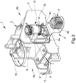
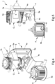
- Other characteristics and advantages of the present invention will be more evident from the description of a preferred, but not exclusive, embodiment of an appliance for the support of biomedical devices during extracorporeal circulation, illustrated as an indication, but not limited to, in the attached tables of drawings in which:
-
Figure 1 is a first axonometric view of an appliance according to the invention in a first configuration of use; -
Figure 2 is a second axonometric view of the appliance inFigure 1 ; -
Figure 3 is an axonometric view of the appliance inFigure 1 in a second configuration of use; -
Figure 4 is an axonometric view of the holding element of the appliance inFigure 1 ; -
Figure 5 is a side elevation view of the holding element inFigure 4 . - With particular reference to these illustrations, reference numeral 1 globally indicates an appliance for the support of biomedical devices during extracorporeal circulation, in particular for the support of an oxygenator and of the relevant pumping assembly.
- The appliance 1 comprises at least one load-bearing
body 2, preferably of the transportable type and positionable on a reference surface, at least one command andcontrol unit 3 operationally connectable to at least one biomedical device to control the functionalities thereof, and at least oneholding element 4 associated with the load-bearingbody 2 and provided with first supportingmeans 5 of a first biomedical device O and with second supporting means 6 of a second biomedical device P. - More particularly, the first biomedical device O is of the type of an oxygenator and the second biomedical device P corresponds to the relevant pumping assembly, e.g. of the type of a centrifugal pump. In the embodiment shown in the figures, the centrifugal pump P, although not part of the present invention, is of the dragging or magnetic levitation type and comprises at least one hollow body inside which is housed a rotor element (impeller) adapted to transfer the venous blood coming from a patient to the oxygenator O and at least one motor adapted to control the rotor element at least in rotation.
- The command and
control unit 3 is connectable to the centrifugal pump P, comprises at least one microprocessor which is programmed to control the relevant motor and is suitably provided with a plurality ofdrives 3a that can be operated by one operator as well as with at least onedisplay 3b for displaying the parameters that can be controlled by means of thedrives 3a. More in detail, thedrives 3a allow controlling at least the number of revolutions of the rotor element and the flow rate delivered. - Appropriately, the load-bearing
body 2 has afront portion 2a, intended to be facing the patient, arear portion 2b, opposite thefront portion 2a and accessible by an operator to actuate thedrives 3a, and twolateral portions 2c interposed between thefront portion 2a and therear portion 2b. - According to the invention, the first supporting means 5 and the second supporting
means 6 are locked to each other and theholding element 4 comprises removable hooking means 7 to the load-bearingbody 2. - The
holding element 4 is advantageously made in a single body piece. - In the preferred embodiment shown in the figures, the
holding element 4 has a substantially slab-like conformation, i.e. the thickness thereof is significantly lower than the other dimensions. - Preferably, the
holding element 4 has at least afirst holding wall 4a with which the first supportingmeans 5 are associated and at least asecond holding wall 4b with which the second supporting means 6 are associated, where the first andsecond holding walls - More in detail, in use, i.e. during the use of the appliance 1 when extracorporeal circulation is applied to a patient, the
first holding wall 4a is substantially arranged (i.e. less the machining tolerances and/or the positioning on a non-planar reference surface) vertically and thesecond holding wall 4b is substantially arranged (i.e. less the machining tolerances and/or the positioning on a non-planar reference surface) horizontally. - The first supporting
means 5 are advantageously arranged at a greater height with respect to the second supportingmeans 6. - The result, therefore, is that, in use, the oxygenator O is arranged on top of the relevant pumping assembly P, thus facilitating, from a fluid-dynamic point of view, the transfer of blood from the pumping assembly P to the oxygenator O. Appropriately, the
holding element 4 comprises at least oneintermediate wall 4c adjacent to thefirst holding wall 4a, arranged substantially transverse thereto and adapted to be arranged, in use, below the oxygenator O. - More in detail, the
intermediate wall 4c is arranged substantially (i.e. less the machining tolerances) parallel to thesecond holding wall 4b and at a greater height with respect thereto. - In the embodiment shown in the figures, the
first holding wall 4a is arranged substantially perpendicular to thesecond holding wall 4b and to theintermediate wall 4c. - The
second holding wall 4b and theintermediate wall 4c define in practice therefore two substantially parallel and staggered planes. - Preferably, the first supporting means 5 comprise at least one
housing seat 8 associable with the oxygenator O and configured to keep the oxygenator itself in suspension on thefirst holding wall 4a. More particularly, thehousing seat 8 has a curvilinear extension in such a way as to at least partly wind the body of the oxygenator O. Thehousing seat 8 is configured so as to receive the oxygenator O by interlocking and/or defines at least one abutment surface on which the oxygenator itself rests. - Advantageously, the first supporting
means 5 are associated with theholding element 4 in a removable manner. More specifically, the first supporting means 5 comprise removable fixing means 5a, e.g. of the type of one or more interlocking elements, to theholding element 4. - Appropriately, the first supporting means 5 are of the disposable type and are intended to be applied to the oxygenator O prior to the sterilization thereof.
- The second supporting
means 6 are instead arranged at thesecond holding wall 4b and are configured to keep the centrifugal pump P in position on the second holding wall itself. - More in detail, the second supporting means 6 can be of the type of a threaded member (as in the embodiment shown in the figures) which passes through the
second holding wall 4b and which is adapted to engage with the containment body of the motor of the centrifugal pump P, or they can be of the interlocking type, slide type or other type known to the expert in the field. - Advantageously, the
hooking means 7 are movable from at least one engagement configuration to a release configuration with the load-bearingbody 2. In the preferred embodiment shown in the figures, thehooking means 7 comprise two hookingelements 7a movable in the direction of mutual close/away movement. More particularly, in the engagement configuration, thesehooking elements 7a are close to each other and are movable in the direction of mutual away movement, counteracting elastic means (not visible in detail in the figures), in order to reach the release configuration. - Appropriately, the hooking means 7 comprise at least one
activation element 7b which can be activated by an operator to bring thehooking elements 7a from the engagement configuration to the release configuration. - In turn, the appliance 1 comprises at least one
gripping element 9 associated with the load-bearingbody 2 and with which thehooking means 7 are adapted to engage in a removable manner. - In the preferred embodiment shown in the figures, the
gripping element 9 is of the type of an element with an elongated shape and protruding from the load-bearingbody 2 so as to define a profile engageable by thehooking elements 7a in the engagement configuration. Alternatively, thegripping element 9 can be recessed with respect to the load-bearingbody 2. - Conveniently, the
gripping element 9 is of the joined type, i.e. its conformation and its dimensions are made according to codified and standardized regulations. In particular, thegripping element 9 corresponds to the profile also found on stretchers used in hospitals. - Advantageously, the appliance 1 comprises at least two
gripping elements 9 which are separate from each other, so as to allow positioning theholding element 4 on the load-bearingbody 2 in at least two different positions that can be selected by the operator according to the specific needs. - More in detail, at least one of the
gripping elements 9 is associated with thefront portion 2a of the load-bearingbody 2, while anothergripping element 9 is associated with at least one of thelateral portions 2c of the load-bearing body itself. This way theholding element 4 is positionable on the load-bearingbody 2, at the operator's will, in at least two positions which are substantially orthogonal to each other. - Preferably, the appliance 1 comprises first protection means 10 of the first biomedical device, i.e. the oxygenator O. More particularly, the first protection means 10 are associated with the load-
bearing body 2 and are shaped so as to surround the oxygenator O. In the preferred embodiment shown in the figures, the first protection means 10 are e.g. of the type of a curved bar. Appropriately, the first protection means 10 are movable from a work position, wherein they are arranged to surround the oxygenator O, and a home position, wherein they are displaced with respect to the work position so as to facilitate the application or removal of the holdingelement 4 to/from the load-bearing body 2. In the embodiment shown in the figures, the first protection means 10 are hinged to the load-bearing body 2 at itsfront portion 2a and rotate upwards to displace from the work position to the home position. More specifically, the first protection means 10 are associated with the load-bearing body 2 in a removable manner so as to reduce the overall dimensions of the appliance 1. - Advantageously, the appliance 1 also comprises second protection means 11 of the second biomedical device, i.e. of the pumping assembly P. More particularly, the second protection means 11 are associated with the load-
bearing body 2 and are shaped so as to surround the pumping assembly P. Appropriately, the second protection means 11 are movable between a work position, wherein they are arranged to surround the pumping assembly P, and a home position, wherein they are displaced from the work position in such a way as to reduce the overall dimensions of the appliance 1. In the embodiment shown in the figures, the second protection means 11 are hinged to the load-bearing body 2 at itsfront portion 2a and rotate upwards to move from the work position to the home position. In particular, the second protection means 11 are of the type of a curved bar shaped so as to resume, in the home position, the profile of thefront portion 2a on which it rests. - The operation of the present invention is as follows.
- Depending on the specific needs, i.e. on the position of the patient and of the other devices that make up the appliance used for extracorporeal circulation, the operator positions the holding
element 4 at thefront portion 2a or thelateral portion 2c of the load-bearing body 2. - In particular, the operator operates the
activation element 7b to bring the hookingelements 7a to the release configuration and, after they have been positioned at thegripping element 9 of interest, releases the activation element itself so as to allow it to be engaged with thegripping element 9. - This way the holding
element 4 is locked together with the load-bearing body 2. The operator then positions the oxygenator O and the pumping assembly P on the holdingelement 4 by means of the first and second supporting means 5 and 6 respectively. - As mentioned above, the oxygenator O is preferably associated with the first supporting means 5 before the sterilization thereof. The first supporting means 5 are, therefore, of the disposable type.
- More in detail, the oxygenator O is fitted inside the
housing seat 8, while the centrifugal pump P is positioned at thesecond holding wall 4b and blocked with respect thereto by means of the threadedmember 6. - After the various devices have been connected to each other and have been connected to the patient, it is possible to start the extracorporeal circulation by monitoring and possibly modifying some parameters of the centrifugal pump P, such as the number of revolutions and the flow rate delivered, by means of the command and
control unit 3. - In case the patient is placed on a stretcher, whether in hospital or out of hospital, it is possible, always operating on the hooking
means 7, to release the holdingelement 4 from the load-bearing body 2. In particular, the operator can operate again on theactivation element 7b to bring the hookingelements 7a to the release configuration and thus remove the holdingelement 4 from the load-bearing body 2. The holdingelement 4 can then be applied to the stretcher's structure, always using the hookingmeans 7. - Appropriately, the holding
element 4 is arranged at a lower height than the patient's one in order to optimize the fluid dynamics of blood circulation. - It has in practice been ascertained that the described invention achieves the intended objects and in particular it is emphasized that it allows optimally positioning the oxygenator and the relevant pumping assembly during the extracorporeal circulation applied to a patient.
- In particular, the shape of the holding element makes it possible to move both the oxygenator and the centrifugal pump at the same time, keeping them in the same mutual position.
- In addition, the hooking means make it possible both to vary the position of the holding element on the load-bearing body and to apply it to a hospital stretcher, thus making it flexible and practical to use.
Claims (15)
- Appliance (1) for the support of biomedical devices during extracorporeal circulation, comprising at least one load-bearing body (2), at least one command and control unit (3) connectable to at least one biomedical device, at least one holding element (4) provided with at least first supporting means (5) of a first biomedical device (O) and with second supporting means (6) of a second biomedical device (P), wherein said first supporting means (5) and said second supporting means (6) are locked to each other and wherein said holding element (4) comprises removable hooking means (7) to said load-bearing body (2), said holding element (4) having at least a first holding wall (4a) with which said first supporting means (5) are associated and having at least a second holding wall (4b) with which said second supporting means (6) are associated, said first and second holding walls (4a, 4b) being arranged transversely to each other, characterized by the fact that said holding element (4) comprises at least one intermediate wall (4c) adjacent to said first holding wall (4a) and arranged substantially transverse thereto, said intermediate wall (4c) being adapted to be arranged, in use, below the first biomedical device (O).
- Appliance (1) according to claim 1, characterized by the fact that said holding element (4) is made in a single body piece.
- Appliance (1) according to one or more of the preceding claims, characterized by the fact that said first and second holding walls (4a, 4b) are arranged, in use, vertically and horizontally, respectively.
- Appliance (1) according to one or more of the preceding claims, characterized by the fact that said intermediate wall (4c) is arranged substantially parallel to said second holding wall (4b) and at a greater height with respect thereto.
- Appliance (1) according to one or more of the preceding claims, characterized by the fact that said first supporting means (5) comprise at least one housing seat (8) of the first biomedical device (O) and configured to keep the latter in suspension on said first holding wall (4a).
- Appliance (1) according to one or more of the preceding claims, characterized by the fact that said first supporting means (5) are associated in a removable manner with said holding element (4).
- Appliance (1) according to claim 6, characterized by the fact that said first supporting means (5) comprise removable fixing means (X) to said holding element (4).
- Appliance (1) according to one or more of the preceding claims, characterized by the fact that said second supporting means (6) are configured to keep the second biomedical device (P) in position on said second holding wall (4b).
- Appliance (1) according to one or more of the preceding claims, characterized by the fact that said hooking means are movable from at least one engagement configuration to a release configuration with said load-bearing body.
- Appliance (1) according to one or more of the preceding claims, characterized by the fact that it comprises at least one gripping element (9) associated with said load-bearing body (2) and by the fact that said hooking means (7) are adapted to engage in a removable manner with said gripping element (9).
- Appliance (1) according to claim 10, characterized by the fact that it comprises at least two of said gripping elements (9) which are separate from each other.
- Appliance (1) according to claim 11, characterized by the fact that said load-bearing body (2) comprises at least one front portion (2a) and at least two lateral portions (2c) arranged transversely with respect to said front portion (2a), said gripping elements (9) being associated with at least said front portion (2a) and with at least one of said lateral portions (2c).
- Appliance (1) according to one or more of the preceding claims, characterized by the fact that it comprises at least one of first protection means (10) of the first biomedical device (O) and second protection means (11) of the second biomedical device (P) associated with said load-bearing body (2).
- Appliance (1) according to claim 13, characterized by the fact that at least one of said first protection means (10) and said second protection means (11) is movable with respect to said load-bearing body (2) from a work position, wherein it is arranged to surround the relevant biomedical device (O, P), and a home position, wherein it is displaced with respect to the work position.
- Appliance (1) according to claim 13 or 14, characterized by the fact that at least one of said first protection means (10) and said second protection means (11) is hinged to said load-bearing body (2) at said front portion (2a).
Applications Claiming Priority (2)
| Application Number | Priority Date | Filing Date | Title |
|---|---|---|---|
| IT102019000001149A IT201900001149A1 (en) | 2019-01-25 | 2019-01-25 | EQUIPMENT FOR SUPPORTING BIOMEDICAL DEVICES DURING EXTRA-BODY CIRCULATION |
| PCT/IB2020/050477 WO2020152589A1 (en) | 2019-01-25 | 2020-01-22 | Appliance for the support of biomedical devices during extracorporeal circulation |
Publications (2)
| Publication Number | Publication Date |
|---|---|
| EP3914318A1 EP3914318A1 (en) | 2021-12-01 |
| EP3914318B1 true EP3914318B1 (en) | 2024-01-17 |
Family
ID=66286718
Family Applications (1)
| Application Number | Title | Priority Date | Filing Date |
|---|---|---|---|
| EP20715189.5A Active EP3914318B1 (en) | 2019-01-25 | 2020-01-22 | Appliance for the support of biomedical devices during extracorporeal circulation |
Country Status (7)
| Country | Link |
|---|---|
| US (1) | US20220080090A1 (en) |
| EP (1) | EP3914318B1 (en) |
| JP (1) | JP2022517343A (en) |
| CN (1) | CN113348003B (en) |
| CA (1) | CA3126546A1 (en) |
| IT (1) | IT201900001149A1 (en) |
| WO (1) | WO2020152589A1 (en) |
Families Citing this family (8)
| Publication number | Priority date | Publication date | Assignee | Title |
|---|---|---|---|---|
| DE112019000979A5 (en) * | 2018-02-26 | 2020-11-05 | Hemovent Gmbh | Holding device for holding an oxygenator and a blood pump |
| IT202100014273A1 (en) * | 2021-05-31 | 2022-12-01 | Eurosets Srl | EQUIPMENT FOR THE SUPPORT OF BIOMEDICAL DEVICES DURING EXTRACORPOREAL CIRCULATION AND RELATED SYSTEM |
| CN114306791B (en) * | 2021-12-23 | 2024-06-18 | 上海宏创医疗科技有限公司 | Control host for extracorporeal circulation equipment |
| CN116807805A (en) * | 2022-01-19 | 2023-09-29 | 心擎医疗(苏州)股份有限公司 | Tray for oxygenator system, adapter assembly, cart and oxygenator system |
| USD1058818S1 (en) * | 2022-02-17 | 2025-01-21 | Eurosets S.R.L. | Biomedical device support |
| USD1058819S1 (en) * | 2022-02-17 | 2025-01-21 | Eurosets S.R.L. | Biomedical device support |
| IT202200007595A1 (en) * | 2022-04-15 | 2023-10-15 | Eurosets Srl | BIOMEDICAL EQUIPMENT AND CASING FOR THE TRANSPORT OF A BIOMEDICAL UNIT |
| WO2026070794A1 (en) * | 2024-09-27 | 2026-04-02 | テルモ株式会社 | Extracorporeal circulation system |
Family Cites Families (14)
| Publication number | Priority date | Publication date | Assignee | Title |
|---|---|---|---|---|
| US6632189B1 (en) * | 1998-09-18 | 2003-10-14 | Edwards Lifesciences Corporation | Support device for surgical systems |
| US6468473B1 (en) * | 1999-02-10 | 2002-10-22 | Terumo Cardiovascular Systems Corporation | Self-contained pack assembly for an extracorporeal blood circuit |
| DE19905937C1 (en) * | 1999-02-12 | 2000-07-13 | Karsten Kirchhof | Mobile heart-lung machine; contains blood regeneration equipment together with control system |
| EP1590019B1 (en) * | 2003-01-14 | 2010-05-05 | Medtronic, Inc. | An active air removal system for an extracorporeal blood circuit |
| US7198751B2 (en) * | 2003-01-14 | 2007-04-03 | Medtronic, Inc. | Disposable, integrated, extracorporeal blood circuit |
| EP1832303A1 (en) * | 2004-11-24 | 2007-09-12 | LIFEBRIDGE Medizintechnik AG | Device for providing extracorporeal blood circulation |
| JP2009160265A (en) * | 2008-01-08 | 2009-07-23 | Terumo Corp | Heart-lung unit and heart-lung apparatus |
| EP2694129B1 (en) * | 2011-04-08 | 2016-01-06 | Universitätsklinikum Regensburg - Anstalt Des Öffentlichen Rechts | Supporting, retaining, and protective apparatus for extracorporeal heart and/or lung support systems |
| CN104271069B (en) * | 2012-04-23 | 2017-04-26 | 泰尔茂株式会社 | Medical apparatus rack |
| US10333895B2 (en) * | 2013-01-18 | 2019-06-25 | Fresenius Vial Sas | Assigning addresses to medical devices in a rack |
| DE102013008434B4 (en) * | 2013-05-17 | 2015-03-12 | Schwing Gmbh | Truck-mounted concrete pump with underride protection |
| JP5755353B2 (en) * | 2014-03-14 | 2015-07-29 | テルモ株式会社 | Artificial lung holder |
| EP4129357B1 (en) * | 2015-10-07 | 2024-06-26 | MAQUET Cardiopulmonary GmbH | Medical device |
| CN108744099A (en) * | 2018-06-19 | 2018-11-06 | 广州军区广州总医院 | The control method that a kind of extracorporeal membrane oxygenation device and its control oxygenated blood supply |
-
2019
- 2019-01-25 IT IT102019000001149A patent/IT201900001149A1/en unknown
-
2020
- 2020-01-22 WO PCT/IB2020/050477 patent/WO2020152589A1/en not_active Ceased
- 2020-01-22 US US17/422,723 patent/US20220080090A1/en active Pending
- 2020-01-22 CN CN202080010790.5A patent/CN113348003B/en active Active
- 2020-01-22 CA CA3126546A patent/CA3126546A1/en active Pending
- 2020-01-22 JP JP2021540070A patent/JP2022517343A/en active Pending
- 2020-01-22 EP EP20715189.5A patent/EP3914318B1/en active Active
Also Published As
| Publication number | Publication date |
|---|---|
| US20220080090A1 (en) | 2022-03-17 |
| CN113348003B (en) | 2025-03-21 |
| JP2022517343A (en) | 2022-03-08 |
| EP3914318A1 (en) | 2021-12-01 |
| CN113348003A (en) | 2021-09-03 |
| CA3126546A1 (en) | 2020-07-30 |
| WO2020152589A1 (en) | 2020-07-30 |
| IT201900001149A1 (en) | 2020-07-25 |
Similar Documents
| Publication | Publication Date | Title |
|---|---|---|
| US20220080090A1 (en) | Appliance for the support of biomedical devices during extracorporeal circulation | |
| JP6389464B2 (en) | Extracorporeal circulation device | |
| US10744254B1 (en) | Automated peritoneal dialysis device | |
| EP1317305B1 (en) | Method and system for closed chest blood flow support | |
| JP5620906B2 (en) | Control unit with a pump module for negative pressure type trauma treatment device | |
| EP1101502B1 (en) | Multipurpose machine for monitoring and control of locoregional therapies in oncology | |
| EP2635319B1 (en) | A portable medical apparatus for cardiopulmonary aid to patients | |
| EP1885409B1 (en) | Blood filtering device | |
| JP2019505267A (en) | Modular blood treatment system, unit and method | |
| AU2001292637A1 (en) | Method and system for closed chest blood flow support | |
| JP2008539034A (en) | Apparatus and method for heat exchange from improved body | |
| US20160166455A1 (en) | Self-contained sterile surgical environment | |
| EP2415491A1 (en) | Extracorporeal blood treatment apparatus | |
| EP4037598A1 (en) | Device for the rapid attachment of biomedical devices | |
| JP6903406B2 (en) | Extracorporeal blood purification system with integrated disinfection case | |
| EP1767232B1 (en) | System for monitoring the extracorporeal circulation and the perfusion of medical flows during cardiopulmonary bypass operations | |
| EP4260884A1 (en) | Biomedical equipment and casing for the transport of a biomedical unit | |
| EP3826599B1 (en) | Medical emergency equipment | |
| US20240226406A1 (en) | Equipment for the support of biomedical devices during extracorporeal circulation and related system | |
| US20250334121A1 (en) | Devices, systems, and methods for priming a fluid management system | |
| CN120027284A (en) | A pipeline line fixing device used for nursing monitoring | |
| HK1099889B (en) | System for monitoring the extracorporeal circulation and the perfusion of medical flows during cardiopulmonary bypass operations |
Legal Events
| Date | Code | Title | Description |
|---|---|---|---|
| STAA | Information on the status of an ep patent application or granted ep patent |
Free format text: STATUS: UNKNOWN |
|
| STAA | Information on the status of an ep patent application or granted ep patent |
Free format text: STATUS: THE INTERNATIONAL PUBLICATION HAS BEEN MADE |
|
| PUAI | Public reference made under article 153(3) epc to a published international application that has entered the european phase |
Free format text: ORIGINAL CODE: 0009012 |
|
| STAA | Information on the status of an ep patent application or granted ep patent |
Free format text: STATUS: REQUEST FOR EXAMINATION WAS MADE |
|
| 17P | Request for examination filed |
Effective date: 20210823 |
|
| AK | Designated contracting states |
Kind code of ref document: A1 Designated state(s): AL AT BE BG CH CY CZ DE DK EE ES FI FR GB GR HR HU IE IS IT LI LT LU LV MC MK MT NL NO PL PT RO RS SE SI SK SM TR |
|
| DAV | Request for validation of the european patent (deleted) | ||
| DAX | Request for extension of the european patent (deleted) | ||
| GRAP | Despatch of communication of intention to grant a patent |
Free format text: ORIGINAL CODE: EPIDOSNIGR1 |
|
| STAA | Information on the status of an ep patent application or granted ep patent |
Free format text: STATUS: GRANT OF PATENT IS INTENDED |
|
| INTG | Intention to grant announced |
Effective date: 20230809 |
|
| GRAS | Grant fee paid |
Free format text: ORIGINAL CODE: EPIDOSNIGR3 |
|
| GRAA | (expected) grant |
Free format text: ORIGINAL CODE: 0009210 |
|
| STAA | Information on the status of an ep patent application or granted ep patent |
Free format text: STATUS: THE PATENT HAS BEEN GRANTED |
|
| AK | Designated contracting states |
Kind code of ref document: B1 Designated state(s): AL AT BE BG CH CY CZ DE DK EE ES FI FR GB GR HR HU IE IS IT LI LT LU LV MC MK MT NL NO PL PT RO RS SE SI SK SM TR |
|
| REG | Reference to a national code |
Ref country code: GB Ref legal event code: FG4D |
|
| REG | Reference to a national code |
Ref country code: CH Ref legal event code: EP |
|
| REG | Reference to a national code |
Ref country code: DE Ref legal event code: R096 Ref document number: 602020024475 Country of ref document: DE |
|
| REG | Reference to a national code |
Ref country code: IE Ref legal event code: FG4D |
|
| P01 | Opt-out of the competence of the unified patent court (upc) registered |
Effective date: 20240214 |
|
| REG | Reference to a national code |
Ref country code: LT Ref legal event code: MG9D |
|
| REG | Reference to a national code |
Ref country code: NL Ref legal event code: MP Effective date: 20240117 |
|
| REG | Reference to a national code |
Ref country code: AT Ref legal event code: MK05 Ref document number: 1650144 Country of ref document: AT Kind code of ref document: T Effective date: 20240117 |
|
| PG25 | Lapsed in a contracting state [announced via postgrant information from national office to epo] |
Ref country code: NL Free format text: LAPSE BECAUSE OF FAILURE TO SUBMIT A TRANSLATION OF THE DESCRIPTION OR TO PAY THE FEE WITHIN THE PRESCRIBED TIME-LIMIT Effective date: 20240117 |
|
| PG25 | Lapsed in a contracting state [announced via postgrant information from national office to epo] |
Ref country code: NL Free format text: LAPSE BECAUSE OF FAILURE TO SUBMIT A TRANSLATION OF THE DESCRIPTION OR TO PAY THE FEE WITHIN THE PRESCRIBED TIME-LIMIT Effective date: 20240117 |
|
| PG25 | Lapsed in a contracting state [announced via postgrant information from national office to epo] |
Ref country code: IS Free format text: LAPSE BECAUSE OF FAILURE TO SUBMIT A TRANSLATION OF THE DESCRIPTION OR TO PAY THE FEE WITHIN THE PRESCRIBED TIME-LIMIT Effective date: 20240517 |
|
| PG25 | Lapsed in a contracting state [announced via postgrant information from national office to epo] |
Ref country code: LT Free format text: LAPSE BECAUSE OF FAILURE TO SUBMIT A TRANSLATION OF THE DESCRIPTION OR TO PAY THE FEE WITHIN THE PRESCRIBED TIME-LIMIT Effective date: 20240117 |
|
| PG25 | Lapsed in a contracting state [announced via postgrant information from national office to epo] |
Ref country code: GR Free format text: LAPSE BECAUSE OF FAILURE TO SUBMIT A TRANSLATION OF THE DESCRIPTION OR TO PAY THE FEE WITHIN THE PRESCRIBED TIME-LIMIT Effective date: 20240418 |
|
| PG25 | Lapsed in a contracting state [announced via postgrant information from national office to epo] |
Ref country code: RS Free format text: LAPSE BECAUSE OF FAILURE TO SUBMIT A TRANSLATION OF THE DESCRIPTION OR TO PAY THE FEE WITHIN THE PRESCRIBED TIME-LIMIT Effective date: 20240417 Ref country code: HR Free format text: LAPSE BECAUSE OF FAILURE TO SUBMIT A TRANSLATION OF THE DESCRIPTION OR TO PAY THE FEE WITHIN THE PRESCRIBED TIME-LIMIT Effective date: 20240117 |
|
| PG25 | Lapsed in a contracting state [announced via postgrant information from national office to epo] |
Ref country code: ES Free format text: LAPSE BECAUSE OF FAILURE TO SUBMIT A TRANSLATION OF THE DESCRIPTION OR TO PAY THE FEE WITHIN THE PRESCRIBED TIME-LIMIT Effective date: 20240117 |
|
| PG25 | Lapsed in a contracting state [announced via postgrant information from national office to epo] |
Ref country code: AT Free format text: LAPSE BECAUSE OF FAILURE TO SUBMIT A TRANSLATION OF THE DESCRIPTION OR TO PAY THE FEE WITHIN THE PRESCRIBED TIME-LIMIT Effective date: 20240117 |
|
| PG25 | Lapsed in a contracting state [announced via postgrant information from national office to epo] |
Ref country code: RS Free format text: LAPSE BECAUSE OF FAILURE TO SUBMIT A TRANSLATION OF THE DESCRIPTION OR TO PAY THE FEE WITHIN THE PRESCRIBED TIME-LIMIT Effective date: 20240417 Ref country code: NO Free format text: LAPSE BECAUSE OF FAILURE TO SUBMIT A TRANSLATION OF THE DESCRIPTION OR TO PAY THE FEE WITHIN THE PRESCRIBED TIME-LIMIT Effective date: 20240417 Ref country code: LT Free format text: LAPSE BECAUSE OF FAILURE TO SUBMIT A TRANSLATION OF THE DESCRIPTION OR TO PAY THE FEE WITHIN THE PRESCRIBED TIME-LIMIT Effective date: 20240117 Ref country code: IS Free format text: LAPSE BECAUSE OF FAILURE TO SUBMIT A TRANSLATION OF THE DESCRIPTION OR TO PAY THE FEE WITHIN THE PRESCRIBED TIME-LIMIT Effective date: 20240517 Ref country code: HR Free format text: LAPSE BECAUSE OF FAILURE TO SUBMIT A TRANSLATION OF THE DESCRIPTION OR TO PAY THE FEE WITHIN THE PRESCRIBED TIME-LIMIT Effective date: 20240117 Ref country code: GR Free format text: LAPSE BECAUSE OF FAILURE TO SUBMIT A TRANSLATION OF THE DESCRIPTION OR TO PAY THE FEE WITHIN THE PRESCRIBED TIME-LIMIT Effective date: 20240418 Ref country code: FI Free format text: LAPSE BECAUSE OF FAILURE TO SUBMIT A TRANSLATION OF THE DESCRIPTION OR TO PAY THE FEE WITHIN THE PRESCRIBED TIME-LIMIT Effective date: 20240117 Ref country code: ES Free format text: LAPSE BECAUSE OF FAILURE TO SUBMIT A TRANSLATION OF THE DESCRIPTION OR TO PAY THE FEE WITHIN THE PRESCRIBED TIME-LIMIT Effective date: 20240117 Ref country code: BG Free format text: LAPSE BECAUSE OF FAILURE TO SUBMIT A TRANSLATION OF THE DESCRIPTION OR TO PAY THE FEE WITHIN THE PRESCRIBED TIME-LIMIT Effective date: 20240117 Ref country code: AT Free format text: LAPSE BECAUSE OF FAILURE TO SUBMIT A TRANSLATION OF THE DESCRIPTION OR TO PAY THE FEE WITHIN THE PRESCRIBED TIME-LIMIT Effective date: 20240117 |
|
| PG25 | Lapsed in a contracting state [announced via postgrant information from national office to epo] |
Ref country code: PT Free format text: LAPSE BECAUSE OF FAILURE TO SUBMIT A TRANSLATION OF THE DESCRIPTION OR TO PAY THE FEE WITHIN THE PRESCRIBED TIME-LIMIT Effective date: 20240517 Ref country code: PL Free format text: LAPSE BECAUSE OF FAILURE TO SUBMIT A TRANSLATION OF THE DESCRIPTION OR TO PAY THE FEE WITHIN THE PRESCRIBED TIME-LIMIT Effective date: 20240117 |
|
| PG25 | Lapsed in a contracting state [announced via postgrant information from national office to epo] |
Ref country code: SE Free format text: LAPSE BECAUSE OF FAILURE TO SUBMIT A TRANSLATION OF THE DESCRIPTION OR TO PAY THE FEE WITHIN THE PRESCRIBED TIME-LIMIT Effective date: 20240117 Ref country code: PT Free format text: LAPSE BECAUSE OF FAILURE TO SUBMIT A TRANSLATION OF THE DESCRIPTION OR TO PAY THE FEE WITHIN THE PRESCRIBED TIME-LIMIT Effective date: 20240517 Ref country code: PL Free format text: LAPSE BECAUSE OF FAILURE TO SUBMIT A TRANSLATION OF THE DESCRIPTION OR TO PAY THE FEE WITHIN THE PRESCRIBED TIME-LIMIT Effective date: 20240117 Ref country code: LV Free format text: LAPSE BECAUSE OF FAILURE TO SUBMIT A TRANSLATION OF THE DESCRIPTION OR TO PAY THE FEE WITHIN THE PRESCRIBED TIME-LIMIT Effective date: 20240117 |
|
| REG | Reference to a national code |
Ref country code: CH Ref legal event code: PL |
|
| PG25 | Lapsed in a contracting state [announced via postgrant information from national office to epo] |
Ref country code: LU Free format text: LAPSE BECAUSE OF NON-PAYMENT OF DUE FEES Effective date: 20240122 |
|
| PG25 | Lapsed in a contracting state [announced via postgrant information from national office to epo] |
Ref country code: LU Free format text: LAPSE BECAUSE OF NON-PAYMENT OF DUE FEES Effective date: 20240122 |
|
| PG25 | Lapsed in a contracting state [announced via postgrant information from national office to epo] |
Ref country code: DK Free format text: LAPSE BECAUSE OF FAILURE TO SUBMIT A TRANSLATION OF THE DESCRIPTION OR TO PAY THE FEE WITHIN THE PRESCRIBED TIME-LIMIT Effective date: 20240117 |
|
| PG25 | Lapsed in a contracting state [announced via postgrant information from national office to epo] |
Ref country code: SM Free format text: LAPSE BECAUSE OF FAILURE TO SUBMIT A TRANSLATION OF THE DESCRIPTION OR TO PAY THE FEE WITHIN THE PRESCRIBED TIME-LIMIT Effective date: 20240117 |
|
| PG25 | Lapsed in a contracting state [announced via postgrant information from national office to epo] |
Ref country code: BE Free format text: LAPSE BECAUSE OF NON-PAYMENT OF DUE FEES Effective date: 20240131 |
|
| REG | Reference to a national code |
Ref country code: DE Ref legal event code: R097 Ref document number: 602020024475 Country of ref document: DE |
|
| PG25 | Lapsed in a contracting state [announced via postgrant information from national office to epo] |
Ref country code: CH Free format text: LAPSE BECAUSE OF NON-PAYMENT OF DUE FEES Effective date: 20240131 |
|
| PG25 | Lapsed in a contracting state [announced via postgrant information from national office to epo] |
Ref country code: EE Free format text: LAPSE BECAUSE OF FAILURE TO SUBMIT A TRANSLATION OF THE DESCRIPTION OR TO PAY THE FEE WITHIN THE PRESCRIBED TIME-LIMIT Effective date: 20240117 Ref country code: CZ Free format text: LAPSE BECAUSE OF FAILURE TO SUBMIT A TRANSLATION OF THE DESCRIPTION OR TO PAY THE FEE WITHIN THE PRESCRIBED TIME-LIMIT Effective date: 20240117 |
|
| PG25 | Lapsed in a contracting state [announced via postgrant information from national office to epo] |
Ref country code: SK Free format text: LAPSE BECAUSE OF FAILURE TO SUBMIT A TRANSLATION OF THE DESCRIPTION OR TO PAY THE FEE WITHIN THE PRESCRIBED TIME-LIMIT Effective date: 20240117 |
|
| PG25 | Lapsed in a contracting state [announced via postgrant information from national office to epo] |
Ref country code: SM Free format text: LAPSE BECAUSE OF FAILURE TO SUBMIT A TRANSLATION OF THE DESCRIPTION OR TO PAY THE FEE WITHIN THE PRESCRIBED TIME-LIMIT Effective date: 20240117 Ref country code: SK Free format text: LAPSE BECAUSE OF FAILURE TO SUBMIT A TRANSLATION OF THE DESCRIPTION OR TO PAY THE FEE WITHIN THE PRESCRIBED TIME-LIMIT Effective date: 20240117 Ref country code: RO Free format text: LAPSE BECAUSE OF FAILURE TO SUBMIT A TRANSLATION OF THE DESCRIPTION OR TO PAY THE FEE WITHIN THE PRESCRIBED TIME-LIMIT Effective date: 20240117 Ref country code: EE Free format text: LAPSE BECAUSE OF FAILURE TO SUBMIT A TRANSLATION OF THE DESCRIPTION OR TO PAY THE FEE WITHIN THE PRESCRIBED TIME-LIMIT Effective date: 20240117 Ref country code: DK Free format text: LAPSE BECAUSE OF FAILURE TO SUBMIT A TRANSLATION OF THE DESCRIPTION OR TO PAY THE FEE WITHIN THE PRESCRIBED TIME-LIMIT Effective date: 20240117 Ref country code: CZ Free format text: LAPSE BECAUSE OF FAILURE TO SUBMIT A TRANSLATION OF THE DESCRIPTION OR TO PAY THE FEE WITHIN THE PRESCRIBED TIME-LIMIT Effective date: 20240117 Ref country code: CH Free format text: LAPSE BECAUSE OF NON-PAYMENT OF DUE FEES Effective date: 20240131 Ref country code: BE Free format text: LAPSE BECAUSE OF NON-PAYMENT OF DUE FEES Effective date: 20240131 |
|
| REG | Reference to a national code |
Ref country code: BE Ref legal event code: MM Effective date: 20240131 |
|
| PG25 | Lapsed in a contracting state [announced via postgrant information from national office to epo] |
Ref country code: MC Free format text: LAPSE BECAUSE OF FAILURE TO SUBMIT A TRANSLATION OF THE DESCRIPTION OR TO PAY THE FEE WITHIN THE PRESCRIBED TIME-LIMIT Effective date: 20240117 |
|
| PLBE | No opposition filed within time limit |
Free format text: ORIGINAL CODE: 0009261 |
|
| STAA | Information on the status of an ep patent application or granted ep patent |
Free format text: STATUS: NO OPPOSITION FILED WITHIN TIME LIMIT |
|
| PG25 | Lapsed in a contracting state [announced via postgrant information from national office to epo] |
Ref country code: MC Free format text: LAPSE BECAUSE OF FAILURE TO SUBMIT A TRANSLATION OF THE DESCRIPTION OR TO PAY THE FEE WITHIN THE PRESCRIBED TIME-LIMIT Effective date: 20240117 |
|
| 26N | No opposition filed |
Effective date: 20241018 |
|
| PG25 | Lapsed in a contracting state [announced via postgrant information from national office to epo] |
Ref country code: IE Free format text: LAPSE BECAUSE OF NON-PAYMENT OF DUE FEES Effective date: 20240122 |
|
| PG25 | Lapsed in a contracting state [announced via postgrant information from national office to epo] |
Ref country code: IE Free format text: LAPSE BECAUSE OF NON-PAYMENT OF DUE FEES Effective date: 20240122 |
|
| PG25 | Lapsed in a contracting state [announced via postgrant information from national office to epo] |
Ref country code: SI Free format text: LAPSE BECAUSE OF FAILURE TO SUBMIT A TRANSLATION OF THE DESCRIPTION OR TO PAY THE FEE WITHIN THE PRESCRIBED TIME-LIMIT Effective date: 20240117 |
|
| PG25 | Lapsed in a contracting state [announced via postgrant information from national office to epo] |
Ref country code: CY Free format text: LAPSE BECAUSE OF FAILURE TO SUBMIT A TRANSLATION OF THE DESCRIPTION OR TO PAY THE FEE WITHIN THE PRESCRIBED TIME-LIMIT; INVALID AB INITIO Effective date: 20200122 |
|
| PG25 | Lapsed in a contracting state [announced via postgrant information from national office to epo] |
Ref country code: HU Free format text: LAPSE BECAUSE OF FAILURE TO SUBMIT A TRANSLATION OF THE DESCRIPTION OR TO PAY THE FEE WITHIN THE PRESCRIBED TIME-LIMIT; INVALID AB INITIO Effective date: 20200122 |
|
| PG25 | Lapsed in a contracting state [announced via postgrant information from national office to epo] |
Ref country code: TR Free format text: LAPSE BECAUSE OF FAILURE TO SUBMIT A TRANSLATION OF THE DESCRIPTION OR TO PAY THE FEE WITHIN THE PRESCRIBED TIME-LIMIT Effective date: 20240117 |
|
| PGFP | Annual fee paid to national office [announced via postgrant information from national office to epo] |
Ref country code: GB Payment date: 20260127 Year of fee payment: 7 |
|
| PGFP | Annual fee paid to national office [announced via postgrant information from national office to epo] |
Ref country code: DE Payment date: 20260128 Year of fee payment: 7 |
|
| PGFP | Annual fee paid to national office [announced via postgrant information from national office to epo] |
Ref country code: IT Payment date: 20260122 Year of fee payment: 7 |
|
| PGFP | Annual fee paid to national office [announced via postgrant information from national office to epo] |
Ref country code: FR Payment date: 20260126 Year of fee payment: 7 |