EP1885409B1 - Blood filtering device - Google Patents
Blood filtering device Download PDFInfo
- Publication number
- EP1885409B1 EP1885409B1 EP06765687.6A EP06765687A EP1885409B1 EP 1885409 B1 EP1885409 B1 EP 1885409B1 EP 06765687 A EP06765687 A EP 06765687A EP 1885409 B1 EP1885409 B1 EP 1885409B1
- Authority
- EP
- European Patent Office
- Prior art keywords
- blood
- peristaltic pump
- filter body
- rotor
- waste liquid
- Prior art date
- Legal status (The legal status is an assumption and is not a legal conclusion. Google has not performed a legal analysis and makes no representation as to the accuracy of the status listed.)
- Not-in-force
Links
- IVQXXIUUJFMWKQ-UHFFFAOYSA-N C[N]1(C)(C)(C)(CC1)=C Chemical compound C[N]1(C)(C)(C)(CC1)=C IVQXXIUUJFMWKQ-UHFFFAOYSA-N 0.000 description 1
Images


Classifications
-
- A—HUMAN NECESSITIES
- A61—MEDICAL OR VETERINARY SCIENCE; HYGIENE
- A61M—DEVICES FOR INTRODUCING MEDIA INTO, OR ONTO, THE BODY; DEVICES FOR TRANSDUCING BODY MEDIA OR FOR TAKING MEDIA FROM THE BODY; DEVICES FOR PRODUCING OR ENDING SLEEP OR STUPOR
- A61M1/00—Suction or pumping devices for medical purposes; Devices for carrying-off, for treatment of, or for carrying-over, body-liquids; Drainage systems
- A61M1/34—Filtering material out of the blood by passing it through a membrane, i.e. hemofiltration or diafiltration
- A61M1/3403—Regulation parameters
- A61M1/341—Regulation parameters by measuring the filtrate rate or volume
-
- A—HUMAN NECESSITIES
- A61—MEDICAL OR VETERINARY SCIENCE; HYGIENE
- A61M—DEVICES FOR INTRODUCING MEDIA INTO, OR ONTO, THE BODY; DEVICES FOR TRANSDUCING BODY MEDIA OR FOR TAKING MEDIA FROM THE BODY; DEVICES FOR PRODUCING OR ENDING SLEEP OR STUPOR
- A61M1/00—Suction or pumping devices for medical purposes; Devices for carrying-off, for treatment of, or for carrying-over, body-liquids; Drainage systems
- A61M1/36—Other treatment of blood in a by-pass of the natural circulatory system, e.g. temperature adaptation, irradiation ; Extra-corporeal blood circuits
- A61M1/3621—Extra-corporeal blood circuits
-
- A—HUMAN NECESSITIES
- A61—MEDICAL OR VETERINARY SCIENCE; HYGIENE
- A61M—DEVICES FOR INTRODUCING MEDIA INTO, OR ONTO, THE BODY; DEVICES FOR TRANSDUCING BODY MEDIA OR FOR TAKING MEDIA FROM THE BODY; DEVICES FOR PRODUCING OR ENDING SLEEP OR STUPOR
- A61M1/00—Suction or pumping devices for medical purposes; Devices for carrying-off, for treatment of, or for carrying-over, body-liquids; Drainage systems
- A61M1/80—Suction pumps
- A61M1/82—Membrane pumps, e.g. bulbs
-
- A—HUMAN NECESSITIES
- A61—MEDICAL OR VETERINARY SCIENCE; HYGIENE
- A61M—DEVICES FOR INTRODUCING MEDIA INTO, OR ONTO, THE BODY; DEVICES FOR TRANSDUCING BODY MEDIA OR FOR TAKING MEDIA FROM THE BODY; DEVICES FOR PRODUCING OR ENDING SLEEP OR STUPOR
- A61M60/00—Blood pumps; Devices for mechanical circulatory actuation; Balloon pumps for circulatory assistance
- A61M60/10—Location thereof with respect to the patient's body
- A61M60/104—Extracorporeal pumps, i.e. the blood being pumped outside the patient's body
- A61M60/109—Extracorporeal pumps, i.e. the blood being pumped outside the patient's body incorporated within extracorporeal blood circuits or systems
- A61M60/113—Extracorporeal pumps, i.e. the blood being pumped outside the patient's body incorporated within extracorporeal blood circuits or systems in other functional devices, e.g. dialysers or heart-lung machines
-
- A—HUMAN NECESSITIES
- A61—MEDICAL OR VETERINARY SCIENCE; HYGIENE
- A61M—DEVICES FOR INTRODUCING MEDIA INTO, OR ONTO, THE BODY; DEVICES FOR TRANSDUCING BODY MEDIA OR FOR TAKING MEDIA FROM THE BODY; DEVICES FOR PRODUCING OR ENDING SLEEP OR STUPOR
- A61M60/00—Blood pumps; Devices for mechanical circulatory actuation; Balloon pumps for circulatory assistance
- A61M60/20—Type thereof
- A61M60/247—Positive displacement blood pumps
- A61M60/253—Positive displacement blood pumps including a displacement member directly acting on the blood
- A61M60/268—Positive displacement blood pumps including a displacement member directly acting on the blood the displacement member being flexible, e.g. membranes, diaphragms or bladders
- A61M60/279—Peristaltic pumps, e.g. roller pumps
Definitions
- the present invention relates to the field of blood filtration, in particular to devices for blood ultrafiltration in hyper-hydrated patients asdefined in appended claim 1.
- Isolated Ultrafiltration is often the only technique which allows saving human lives in the context of intensive therapy both for resuscitation and in cardiology. Although the technique is simple, it is carried out with complex dialysis equipments, which imply not only handling problems, but also evident problems for their high purchase, managing and maintenance costs.
- US patent 6,514,226 teaches the treatment of patients affected by Congestive Heart Failure (CHF) by means of perfusion of a hemofilter through a suitable peristaltic pump. A depression is applied to the filter, which produces an ultrafiltration liquid; the amount of removed ultrafiltration liquid depends on the level of cardiocirculatory overload.
- CHF Congestive Heart Failure
- a machine for extracorporeal treatment of blood substantially comprises withdrawal and return pipes, a pump for blood transfer, a hemofilter and control devices.
- the pump and the hemofilter are separated and mounted on a device controlling system operation.
- This machine is then mounted on a wheeled trestle.
- the whole system can be easily moved near the patient, however the overall size is considerable and it is unsuitable for use outside a hospital.
- a similar system is shown in US 2004054315 .
- EP 0,005,266 A1 discloses a haemodialysis apparatus wherein a peristaltic pump and filter bodies are mounted to an apparatus body independently to each other. Therefore, for each treatment, filters and hoses need to be replaced by medical personnel.
- the present invention is focused to solve the above mentioned problems by providing a device formed by a hemofilter incorporated with the pumping system.
- the present invention provides an extremely simplified construction of a device for blood filtration, in particular ultrafiltration, which solves the disadvantages of the state of the art, especially with respect to complexity of traditional hemodialysis machines, portability, readiness of use, cost and training of people dedicated to patient's treatment
- the device of the present invention comprises a hemodialysis filter, in which a pump has been incorporated, which is suited to filter feeding directly from patient, thus substantially reducing blood withdrawal and return catheter tubing length.
- catheter tubing length not only from the point of view of working of the device, namely reducing the complexity of its components and its maintenance, but also from the point of view of the patient undergoing ultrafiltration.
- the possibility to shorten tubing makes the device more easy to handle, for example it can be placed directly side by side the patient, but requires much less blood to prime the pump that assures blood transfer through the filter.
- a portable device such as provided by the present invention is of immediate application in all the possible emergency situations, for example outside hospital premises, at home, in ambulance or in natural catastrophe situations.
- the device of the present invention is suitable for use in hemodialysis, in particular in Continuous Slow Ultrafiltration (shortly, SCUF), in Continuous Artero-Venous Hemofiltration (CAVH), or in Continuous Veno-Venous Hemofiltration (CVVH).
- SCUF Continuous Slow Ultrafiltration
- CAVH Continuous Artero-Venous Hemofiltration
- CVVH Continuous Veno-Venous Hemofiltration
- the device of the present invention is substantially disclosed in the main claim and in the dependent claims.
- a blood filtering device is generally indicated as 1. It comprises a filter body 3, having an elongated shape, cylindrical in particular, with a circular section.
- the filter body 3 known also as hemofilter, contains membranes apt to carry out the required filtration for the treatments which will be disclosed in the following.
- a delivery flexible hose is connected 5 for the blood to be filtered which, as it will be appreciated in the following, is apt to be connected to further ducts, not shown, linked to a circulation system for the taking of blood to be treated, for example to a artero-venous fistula.
- the delivery hose 5 is inserted and flows into the filter body 3.
- the filter body 3 further comprises an outlet port 6, to which a return hose 7 is connected for the filtered blood, and a discharge port 8, to which a discharge hose 9 is connected for the waste liquid which is accumulated inside the filter body 3.
- Said inlet port is formed at one of the ends of the filter body 3, while the outlet port 6 is positioned at the opposite end.
- the devise comprises an independent driving body 2 housing, in a case 16, a peristaltic pump 10 divided in a peristaltic pump rotor 11 and peristaltic pump motor 12 which, in the present embodiment, is an electric stepper motor.
- the rotor 11 is housed inside a peristaltic pump rotor chamber 13, which is apt to house inside a distal portion, with respect to the patient, of said flexible delivery hose 5, for obtaining a peristaltic effect.
- Said case 16 where it forms the rotor chamber 13, is shaped at the top in such a way to constitute a seat or resting base 11, i.e. means for maintaining said filter body 3 in the vertical working position, wherein said inlet port, integrated into the bottom end of the filter body 3, is placed at said rotor chamber 13.
- the case 16 operates as a basement on which the filter is positioned with a reversible joining which may be a forced or a catch joint, a screw coupling, a bayonet coupling or other equivalents.
- the electric motor 12 constitutes peristaltic pump driving means 10, being connected to the rotor 11 by a drive shaft.
- the electric motor can be separated from said rotor, the latter being engageable by crank means for the manual driving of the rotor.
- the filter body 3, with the delivery, return, discharge flexible hoses 5, 7, 9 form a disposable kit to be associated to said case.
- the filter body 3 is connected to a bag or to another drainage container, for the collection of the waste liquid.
- the discharge hose 9 comprises an flow adjustment system 15, for instance a Redon system.
- a filtering pressure adjustment system may be provided too.
- a bellows pump 17 connected to the filter body is shown, utilized for triggering of the intake of the waste liquid, which could be also drawn out by a further peristaltic pump.
- the kit will be connected to a patient circulatory system, so as to fill with blood the delivery hose 5 for triggering the peristaltic pump 10, which provides to fill the hemofilter.
- the hemofilter According to the characteristics of the hemofilter, it is possible to carry out a patient hemodialysis without hospitalizing or moving him, in consideration of the remarkable lightness and operational easiness of the device.
- the body 2 with the peristaltic pump is ready for a new operation, while the filter and the hoses can be disposed.
- a blood filtering device according to the invention is described, generally indicated by 100.
- the first indicated with 101, forming the basement of the device 100, intended to be rested on a work top.
- a filter body 103 is housed, having an elongated shape and particularly cylindrical, with a circular section.
- the filter body 103 contains membranes apt to carry out the required filtration in the treatments which will be described in the following.
- It comprises an inlet port 104, for the inlet of the blood to be filtered, to which a delivery flexible hose 105 is connected for the blood to be filtered which, as it will be appreciated hereinafter, is apt to be connected to further ducts, not shown, and to a circulatory system for the taking of blood to be treated.
- the filter body 103 further comprises an outlet port 106, to which a filtered blood return hose 107 is connected, and a discharge port 108, to which a discharge hose 109 is connected for the waste liquid lowing from the inside of the filter body 103.
- Said inlet port 104 is positioned at one of the ends of the filter body 103, while the outlet port 106 is positioned at the opposite end.
- the second half-body 102 completely hollow, has a bottom 110, resting on the first half-body 101, and a projection 111 projecting from said bottom 110 and inserted into a corresponding recess 112 in the first half-body 101.
- Said half-body 102 further has a dome covering 151, transparent, provided with an opening operating as handle 152.
- a room 113 is formed inside the second half-body 102, having a height substantially equal to that of the whole device 100, wherein said filter body 103 is housed.
- the working position of the filter body 104 is vertical, with said inlet port 104 placed at the lower end of the filter 103.
- the device 100 comprises a pair of peristaltic pump rotor chambers, symmetrically placed with respect to the centre plane, so as to have the filter body substantially placed between them, but on a rear plane.
- Said chambers are formed by a case which, in the present embodiment, is made of plastic by injection moulding and forms a single piece defining said bottom 110.
- Each chamber 114, 115 has entry and exit holes of a respective flexible hose and houses a peristaltic pump rotor, respectively indicated by 117, 118.
- This rotor 117, 118 is of the roller-type having two lobes, conveniently mounted on low friction bearings.
- the chambers 114, 115 are closed by a suitable lid 132 which is part of the case 116.
- the case 116 comprises respective engagement holes 121, 122 for the introduction of a respective driving shaft, which will be discussed hereinafter, driving the rotors 117, 118.
- a portion of said delivery flexible hose 105 is positioned, for supplying the filter body 103 with blood to be filtered. Accordingly, inside a second peristaltic pump rotor chamber 115 a portion of the discharge flexible hose 109 is positioned, for the suction of the waste liquid from the filter body 103.
- said case 116 extending from the bottom 110 with said projection 111, forms a resting base for the lower end of said filter body 103, and the inlet port 104 is placed in proximity of the corresponding first peristaltic pump rotor chamber 114.
- the case 116 defines means for maintaining the filter body 103 in a working position and the room 113, housing said filter body 103, is adjacent to the first rotor chamber 114, so as to minimize the length of the delivery flexible hose 105.
- the case 116 i.e. the bottom of the second half-body 102, is extended so as to define a closed space comprising said room 113 and housing a collecting bag 119, for the drainage of the waste liquid drawn out of the filter body 103.
- a mounting hanger 120 is housed inside the second half-body 102, to which the bag is hung.
- the bag can substantially be of a conventional type.
- the first half-body 101 comprises an external case 140 and a boxed basement 141, made of metallic material, having a upper sheet 142 to which respective first and second electric motors 143, 144 are connected for driving the rotors 117, 118. They constitute driving means of said rotors.
- Each shaft is provided with retractable fins allowing a safe securing with the corresponding rotor hole, regardless the angular position thereof.
- a control system 147 is placed with a triggering and control knob 148, frontally placed on the first half-body 101.
- a pair of projecting elements 149 project to the upper inside a boxed container, of a catch joint system, apt to be engaged, through said upper sheet 142 , into corresponding notches 134 formed in the bottom 110 of the second half-body 102.
- control system 147 produces a signal of safe engagement between the two half-bodies 101, 102, i.e. allowing the operation of the peristaltic pumps.
- the electric motors 143, 144 are of the stepper type.
- the motors 143, 144, with their respective shaft 145, the rotors 117, 118 inserted in their respective rotor chambers 114, 115, and the corresponding flexible hose 105, 109 form peristaltic pump means for the circulation of the blood to be treated and of the waste liquid.
- the motors 143, 144 with their respective shaft 145 in turn forms means for driving the above mentioned rotors, and such means are housed in the boxed basement 141 of the device 1.
- the basement is apt to be placed on any plane.
- This basement 141 comprises means for measuring the weight of the case, i.e. the weight of the liquid contained therein. They operate through stems 150 on which the basement 141 is mounted.
- the present disclosure relates to methods for treating a patient in need of ultrafiltration hemodialysis with the above disclosed device.
- the method comprises connecting the patient to said device, passing blood of said patient through said device until treatment of blood according to the determination of the person skilled in the art.
- said patient in need of ultrafiltration hemodialysis is a hyperhydrated patient.
- the method is also suitable for the treatment of isolated ultrafiltration, the method is carried out as above described.
- Isolated ultrafiltration can be carried out in an intensive case environment, for example for resuscitation purpose or to carry out a cardiologic treatment.
- the method is suitable for the treatment o a patient affected by congestive heart failure.
- the method allows to perform ultrafiltration hemodialysis in a patient outside hospital premises, by using the device disclosed herein.
- ultrafiltration hemodialysis is carried out at patient's home, conveniently, the patient lies in bed or is in a convenient position, for example in an armchair.
- the method is easily carried out in an ambulance.
- the method can be carried out also in extremely critical conditions, for example in natural disaster of war fields.
- Continuous Artero-Venous Hemofiltration (CAVH), or Continuous Veno-Venous Hemofiltration (CVVH) are another preferred embodiment of the method disclosed herein.
Description
- The present invention relates to the field of blood filtration, in particular to devices for blood ultrafiltration in hyper-hydrated patients asdefined in appended claim 1.
- Isolated Ultrafiltration is often the only technique which allows saving human lives in the context of intensive therapy both for resuscitation and in cardiology. Although the technique is simple, it is carried out with complex dialysis equipments, which imply not only handling problems, but also evident problems for their high purchase, managing and maintenance costs.
- In order to remove liquids from hyperhydrated patients in critical cardiovascular conditions, this technique is preferred to standard hemodialysis, thanks its characteristic feature of low flow both of blood feeding and ultrafiltration. The absence of dialysis bath and the relative circulation and control systems makes possible to design an equipment for Slow Continuous Ultrafiltration (S.C.U.F.). for a review of this technique, see Merril, RH; "The technique of slow continuous ultrafiltration. Steps to maintain fluid balance without hemodynamic instability"; J. Crit. Illn.; 1991 Mar; 6(3) : 289-94 .
-
US patent 6,514,226 teaches the treatment of patients affected by Congestive Heart Failure (CHF) by means of perfusion of a hemofilter through a suitable peristaltic pump. A depression is applied to the filter, which produces an ultrafiltration liquid; the amount of removed ultrafiltration liquid depends on the level of cardiocirculatory overload. - A more complex system is disclosed in
US 6,685,664 , wherein a machine for extracorporeal treatment of blood substantially comprises withdrawal and return pipes, a pump for blood transfer, a hemofilter and control devices. The pump and the hemofilter are separated and mounted on a device controlling system operation. This machine is then mounted on a wheeled trestle. The whole system can be easily moved near the patient, however the overall size is considerable and it is unsuitable for use outside a hospital. A similar system is shown inUS 2004054315 . -
EP 0,005,266 A1 discloses a haemodialysis apparatus wherein a peristaltic pump and filter bodies are mounted to an apparatus body independently to each other. Therefore, for each treatment, filters and hoses need to be replaced by medical personnel. - A general common knowledge of this field and, in particular, the above mentioned patent and non-patent references are referred to for a complete picture of the state of the art.
- There is still the need to have available a portable device for blood ultrafiltration, which maintains the efficacy of the known devices and of dialysis machines and allows its use outside the hospital premises, for example at patient's home, in the ambulance, in emergency situations, for example in field hospitals, in natural disaster situations, rescue in wilderness or places difficult to reach. Another need is to minimize the length of connecting tubes between patient and device, so as to use less blood possible to prime the pump-filter system and anyway reduce blood residence time outside blood circle.
- The present invention is focused to solve the above mentioned problems by providing a device formed by a hemofilter incorporated with the pumping system.
- The present invention provides an extremely simplified construction of a device for blood filtration, in particular ultrafiltration, which solves the disadvantages of the state of the art, especially with respect to complexity of traditional hemodialysis machines, portability, readiness of use, cost and training of people dedicated to patient's treatment
- The device of the present invention, as defined in appended claim 1, comprises a hemodialysis filter, in which a pump has been incorporated, which is suited to filter feeding directly from patient, thus substantially reducing blood withdrawal and return catheter tubing length.
- It is to be underlined that it is very important to reduce catheter tubing length, not only from the point of view of working of the device, namely reducing the complexity of its components and its maintenance, but also from the point of view of the patient undergoing ultrafiltration. In fact, the possibility to shorten tubing makes the device more easy to handle, for example it can be placed directly side by side the patient, but requires much less blood to prime the pump that assures blood transfer through the filter. It is evident that a portable device, such as provided by the present invention is of immediate application in all the possible emergency situations, for example outside hospital premises, at home, in ambulance or in natural catastrophe situations.
- The device of the present invention is suitable for use in hemodialysis, in particular in Continuous Slow Ultrafiltration (shortly, SCUF), in Continuous Artero-Venous Hemofiltration (CAVH), or in Continuous Veno-Venous Hemofiltration (CVVH).
- The device of the present invention is substantially disclosed in the main claim and in the dependent claims.
- The present invention will be disclosed hereinafter according to two embodiments thereof, provided for a illustrative non-limiting purpose with reference to the annexed drawings wherein:
- *
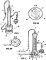
figure 1 shows a perspective view of a blood filtering device; - *
figure 2 shows an elevational section of the device offigure 1 ; - *
figures 2A and 2B show, according to respective planes A-A and B-B infigure 2 , two details of the device offigure 1 ; - *
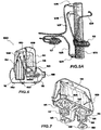
figure 3 shows a perspective view of an embodiment of the blood filtering device according to the invention, in a separated configuration; - *
figure 4 shows a perspective view of the device offigure 3 , in a joined configuration; - *
figure 5 shows an elevational section of the device offigures 3 and 4 ; - *
figure 5A shows an operational diagram of a detail of the device offigures 3 and 4 ; - *
figure 6 shows an elevational section, according to a plane perpendicular to that offigure 5 , of the device offigure 3 and 4 ; - *
figure 7 shows a bottom and partially exploded perspective view of the top portion of the device offigure 3 and 4 ; - *
figure 8 shows a perspective view of the content of the bottom portion of the device offigures 3 and 4 ; - *
figure 9 shows a perspective view of a detail shown infigure 8 ; and - *
figure 10 illustrates the use of the device offigures 3 and 4 . - With reference to
figures 1, 2, 2A and 2B , a blood filtering device is generally indicated as 1. It comprises a filter body 3, having an elongated shape, cylindrical in particular, with a circular section. the filter body 3, known also as hemofilter, contains membranes apt to carry out the required filtration for the treatments which will be disclosed in the following. - It comprises an inlet port integrated into the filter body, for the inlet of the blood to be filtered, to which a delivery flexible hose is connected 5 for the blood to be filtered which, as it will be appreciated in the following, is apt to be connected to further ducts, not shown, linked to a circulation system for the taking of blood to be treated, for example to a artero-venous fistula. Essentially, the delivery hose 5 is inserted and flows into the filter body 3.
- The filter body 3 further comprises an outlet port 6, to which a return hose 7 is connected for the filtered blood, and a discharge port 8, to which a discharge hose 9 is connected for the waste liquid which is accumulated inside the filter body 3.
- Said inlet port is formed at one of the ends of the filter body 3, while the outlet port 6 is positioned at the opposite end.
- Further, the devise comprises an independent driving body 2 housing, in a case 16, a peristaltic pump 10 divided in a peristaltic pump rotor 11 and peristaltic pump motor 12 which, in the present embodiment, is an electric stepper motor.
- The rotor 11 is housed inside a peristaltic
pump rotor chamber 13, which is apt to house inside a distal portion, with respect to the patient, of said flexible delivery hose 5, for obtaining a peristaltic effect. - Said case 16, where it forms the
rotor chamber 13, is shaped at the top in such a way to constitute a seat or resting base 11, i.e. means for maintaining said filter body 3 in the vertical working position, wherein said inlet port, integrated into the bottom end of the filter body 3, is placed at saidrotor chamber 13. - In this configuration, the case 16 operates as a basement on which the filter is positioned with a reversible joining which may be a forced or a catch joint, a screw coupling, a bayonet coupling or other equivalents.
- The electric motor 12 constitutes peristaltic pump driving means 10, being connected to the rotor 11 by a drive shaft.
- According to a modification, the electric motor can be separated from said rotor, the latter being engageable by crank means for the manual driving of the rotor.
- It can be noted that the filter body 3, with the delivery, return, discharge flexible hoses 5, 7, 9 form a disposable kit to be associated to said case.
- Through the discharge hose 9, the filter body 3 is connected to a bag or to another drainage container, for the collection of the waste liquid.
- In this section, the discharge hose 9 comprises an flow adjustment system 15, for instance a Redon system. A filtering pressure adjustment system may be provided too. In the figures, a
bellows pump 17 connected to the filter body is shown, utilized for triggering of the intake of the waste liquid, which could be also drawn out by a further peristaltic pump. - It is intended that, for the employment of the device herein described, it is sufficient to use a new kit comprising filter and hoses, inserting on site the delivery hose into the peristaltic
pump rotor chamber 13. - The kit will be connected to a patient circulatory system, so as to fill with blood the delivery hose 5 for triggering the peristaltic pump 10, which provides to fill the hemofilter.
- According to the characteristics of the hemofilter, it is possible to carry out a patient hemodialysis without hospitalizing or moving him, in consideration of the remarkable lightness and operational easiness of the device.
- At the end of the treatment, the body 2 with the peristaltic pump is ready for a new operation, while the filter and the hoses can be disposed.
- With reference to
figures 3 to 10 , a blood filtering device according to the invention is described, generally indicated by 100. - It can be divided into two detachable half-bodies, the first, indicated with 101, forming the basement of the
device 100, intended to be rested on a work top. - Inside the second half-body, indicated by 102, a
filter body 103 is housed, having an elongated shape and particularly cylindrical, with a circular section. - The
filter body 103 contains membranes apt to carry out the required filtration in the treatments which will be described in the following. - It comprises an
inlet port 104, for the inlet of the blood to be filtered, to which a deliveryflexible hose 105 is connected for the blood to be filtered which, as it will be appreciated hereinafter, is apt to be connected to further ducts, not shown, and to a circulatory system for the taking of blood to be treated. - The
filter body 103 further comprises anoutlet port 106, to which a filteredblood return hose 107 is connected, and adischarge port 108, to which adischarge hose 109 is connected for the waste liquid lowing from the inside of thefilter body 103. - Said
inlet port 104 is positioned at one of the ends of thefilter body 103, while theoutlet port 106 is positioned at the opposite end. - The second half-body 102, completely hollow, has a bottom 110, resting on the first half-body 101, and a projection 111 projecting from said bottom 110 and inserted into a corresponding recess 112 in the first half-body 101.
- Said half-body 102 further has a dome covering 151, transparent, provided with an opening operating as handle 152.
- Thank to the projection 111, a room 113 is formed inside the second half-body 102, having a height substantially equal to that of the
whole device 100, wherein saidfilter body 103 is housed. - In such a way, the working position of the
filter body 104 is vertical, with saidinlet port 104 placed at the lower end of thefilter 103. - At the bottom 110 of the second half-body 102, the
device 100 comprises a pair of peristaltic pump rotor chambers, symmetrically placed with respect to the centre plane, so as to have the filter body substantially placed between them, but on a rear plane. - Said chambers, respectively indicated by 114 and 115, are formed by a case which, in the present embodiment, is made of plastic by injection moulding and forms a single piece defining said bottom 110.
- Each
chamber 114, 115 has entry and exit holes of a respective flexible hose and houses a peristaltic pump rotor, respectively indicated by 117, 118. Thisrotor chambers 114, 115 are closed by a suitable lid 132 which is part of thecase 116. - At the
rotors case 116 comprises respective engagement holes 121, 122 for the introduction of a respective driving shaft, which will be discussed hereinafter, driving therotors - Inside a first peristaltic pump rotor chamber 114 a portion of said delivery
flexible hose 105 is positioned, for supplying thefilter body 103 with blood to be filtered. Accordingly, inside a second peristaltic pump rotor chamber 115 a portion of the dischargeflexible hose 109 is positioned, for the suction of the waste liquid from thefilter body 103. - It should be noted how said
case 116, extending from the bottom 110 with said projection 111, forms a resting base for the lower end of saidfilter body 103, and theinlet port 104 is placed in proximity of the corresponding first peristalticpump rotor chamber 114. Thus, thecase 116 defines means for maintaining thefilter body 103 in a working position and the room 113, housing saidfilter body 103, is adjacent to thefirst rotor chamber 114, so as to minimize the length of the deliveryflexible hose 105. - The
case 116, i.e. the bottom of the second half-body 102, is extended so as to define a closed space comprising said room 113 and housing a collectingbag 119, for the drainage of the waste liquid drawn out of thefilter body 103. - To this purpose, a mounting hanger 120 is housed inside the second half-body 102, to which the bag is hung. The bag can substantially be of a conventional type.
- The first half-body 101 comprises an external case 140 and a
boxed basement 141, made of metallic material, having a upper sheet 142 to which respective first and second electric motors 143, 144 are connected for driving therotors - From the motors 143, 144 respective driving shaft 145 vertically project, apt to engage the
rotors - Between the motors, electrically supplied according to conventional systems, a
control system 147 is placed with a triggering andcontrol knob 148, frontally placed on the first half-body 101. - From there, a pair of projecting elements 149 project to the upper inside a boxed container, of a catch joint system, apt to be engaged, through said upper sheet 142 , into corresponding notches 134 formed in the bottom 110 of the second half-body 102.
- Further, the
control system 147 produces a signal of safe engagement between the two half-bodies 101, 102, i.e. allowing the operation of the peristaltic pumps. - The electric motors 143, 144 are of the stepper type.
- The motors 143, 144, with their respective shaft 145, the
rotors respective rotor chambers 114, 115, and the correspondingflexible hose - In the present embodiment, the motors 143, 144 with their respective shaft 145 in turn forms means for driving the above mentioned rotors, and such means are housed in the boxed
basement 141 of the device 1. The basement is apt to be placed on any plane. Thisbasement 141 comprises means for measuring the weight of the case, i.e. the weight of the liquid contained therein. They operate through stems 150 on which thebasement 141 is mounted. - When required, it is therefore possible to easily couple the first half-body 101 placing above it the second half-body 102, so as to insert the projection 111 in the respective cavity 112, obliged engagement in consideration of the structure asymmetry.
- Now, having triggered the circuit by connecting it to the artero-venous system of a patient, it is possible to drive both the peristaltic pumps, so as to start the blood filtering.
- According to this embodiment of the device, it is possible to control the basic operation data, namely, the amount of extracted discharge liquid, filtration speed, etc.
- In another aspect, the present disclosure relates to methods for treating a patient in need of ultrafiltration hemodialysis with the above disclosed device.
- The method comprises connecting the patient to said device, passing blood of said patient through said device until treatment of blood according to the determination of the person skilled in the art.
- In a first embodiment of the method, said patient in need of ultrafiltration hemodialysis is a hyperhydrated patient.
- The method is also suitable for the treatment of isolated ultrafiltration, the method is carried out as above described. Isolated ultrafiltration can be carried out in an intensive case environment, for example for resuscitation purpose or to carry out a cardiologic treatment.
- In a preferred embodiment, the method is suitable for the treatment o a patient affected by congestive heart failure.
- In general, the method allows to perform ultrafiltration hemodialysis in a patient outside hospital premises, by using the device disclosed herein. In a preferred embodiment, ultrafiltration hemodialysis is carried out at patient's home, conveniently, the patient lies in bed or is in a convenient position, for example in an armchair.
- Under urgency conditions, the method is easily carried out in an ambulance. In another embodiment, the method can be carried out also in extremely critical conditions, for example in natural disaster of war fields. Continuous Artero-Venous Hemofiltration (CAVH), or Continuous Veno-Venous Hemofiltration (CVVH) are another preferred embodiment of the method disclosed herein.
- Execution of all these methods is absolutely conventional and within the skill of the ordinary practitioner in this art, who only need of his or her basic knowledge. Usual medical handbooks are a possible source of information, for example Merck Manual of Diagnosis and Therapy.
- The person skilled in this art can carry out a number of further modifications and variants to the blood filtering devices above described in order to satisfy additional and temporary needs, which, however, are all comprised within the scope of protection of the present invention, as defined in the appended claims.
Claims (8)
- Blood isolated ultrafiltration device (1), comprising:* a filter body (103), having an inlet port (104) and an outlet port (106) for the blood to be filtered and a discharge port (108) for the extracted waste liquid;* a case (116) extending to form a closed space comprising a room (113), housing said filter body (103) in a working position, housing a waste liquid collecting bag (119), and forming, in separated portions thereof, two peristaltic pump rotor chambers (114, 115) of a peristaltic pump means, respectively housing a corresponding peristaltic pump rotor (117, 118);* a delivery flexible hose (105) of the blood to be filtered, connected to said inlet port (104) and to further ducts to be linked to a circulatory system, including a portion thereof arranged inside the first peristaltic pump rotor chamber (114) for obtaining a peristaltic effect for the circulation of blood to be filtered;* a discharge hose (109) of the waste liquid from the filter body (103), connected to said discharge port (108), including a portion thereof arranged inside the second peristaltic pump rotor chamber (115) for obtaining a peristaltic effect for the waste liquid circulation;• a blood return hose (107) connected to said outlet port (106) of the filter body (103),• a basement (141) apt to be rested on a plane, housing a driving means which comprises a pair of electric motors (143, 144) for driving the peristaltic pump rotors (117, 118), each placed axially with a respective drive shaft (145), said filter body (103) with the delivery flexible hose (105), the blood return hose (107) and the discharge hose (109) being housed within said case (116), with the waste liquid collecting bag (119), said rotor chambers (114, 115) and the corresponding peristaltic pump rotors (117, 118), said case (116) comprising respective engagement holes (121, 122) at the peristaltic pump rotors (117, 118) for the introduction of said respective drive shaft (145) of the basement (141).
- Device (1) according to claim 1, wherein said filter body (103) has an elongated shape, with said inlet port (104) placed at one of the ends thereof, said working position determining said end be placed in proximity of said second rotor chamber (115).
- Device (1) according to claim 1, wherein said case (116) is mounted by a catch joint system, providing the allowance to the triggering of the driving means (143, 144).
- Device (1) according to claim 1, wherein the electric motors (143, 144) are of the stepper type.
- Device (1) according to claim 1, wherein the basement (141) comprises means for measuring the weight of the case, i.e. of the waste liquid contained therein.
- Device (1) according to claim 5, wherein the basement (141) is mounted on stems (150) through which said means for measuring the weight operate.
- Device (1) according to claim 1, wherein the rotor (117, 118) inside the rotor chamber (114, 115) is of two-lobes type.
- Device (1) according to claim 7, wherein the rotor (117, 118) inside the rotor chamber (114, 115) is of roller type.
Applications Claiming Priority (2)
| Application Number | Priority Date | Filing Date | Title |
|---|---|---|---|
| IT000247A ITRM20050247A1 (en) | 2005-05-19 | 2005-05-19 | ULTRAFILTRATION EQUIPMENT ISOLATED IN ACUTE. |
| PCT/IB2006/051579 WO2006123308A2 (en) | 2005-05-19 | 2006-05-18 | Blood filtering device |
Publications (2)
| Publication Number | Publication Date |
|---|---|
| EP1885409A2 EP1885409A2 (en) | 2008-02-13 |
| EP1885409B1 true EP1885409B1 (en) | 2017-11-01 |
Family
ID=37209488
Family Applications (1)
| Application Number | Title | Priority Date | Filing Date |
|---|---|---|---|
| EP06765687.6A Not-in-force EP1885409B1 (en) | 2005-05-19 | 2006-05-18 | Blood filtering device |
Country Status (6)
| Country | Link |
|---|---|
| US (1) | US8211047B2 (en) |
| EP (1) | EP1885409B1 (en) |
| JP (1) | JP2008540018A (en) |
| CN (1) | CN101208119B (en) |
| IT (1) | ITRM20050247A1 (en) |
| WO (1) | WO2006123308A2 (en) |
Cited By (6)
| Publication number | Priority date | Publication date | Assignee | Title |
|---|---|---|---|---|
| US10722631B2 (en) | 2018-02-01 | 2020-07-28 | Shifamed Holdings, Llc | Intravascular blood pumps and methods of use and manufacture |
| US11185677B2 (en) | 2017-06-07 | 2021-11-30 | Shifamed Holdings, Llc | Intravascular fluid movement devices, systems, and methods of use |
| US11511103B2 (en) | 2017-11-13 | 2022-11-29 | Shifamed Holdings, Llc | Intravascular fluid movement devices, systems, and methods of use |
| US11654275B2 (en) | 2019-07-22 | 2023-05-23 | Shifamed Holdings, Llc | Intravascular blood pumps with struts and methods of use and manufacture |
| US11724089B2 (en) | 2019-09-25 | 2023-08-15 | Shifamed Holdings, Llc | Intravascular blood pump systems and methods of use and control thereof |
| US11964145B2 (en) | 2019-07-12 | 2024-04-23 | Shifamed Holdings, Llc | Intravascular blood pumps and methods of manufacture and use |
Families Citing this family (14)
| Publication number | Priority date | Publication date | Assignee | Title |
|---|---|---|---|---|
| CN102482122B (en) * | 2009-06-07 | 2015-09-30 | 过滤有限公司 | The medical filter of circulation is used to carry out the apparatus and method of drainage |
| IT1399646B1 (en) * | 2010-04-21 | 2013-04-26 | Rand Srl | FILTRATION AND PUMPING SYSTEM FOR MEDICAL USE |
| ITMO20130194A1 (en) * | 2013-07-01 | 2015-01-02 | Eurosets Srl | BLOOD BLOOD FILTERING DEVICE |
| EP3104915B1 (en) | 2014-02-14 | 2019-11-13 | Green, Richard Dennis | Gas removal systems and methods |
| US10874805B2 (en) | 2014-02-14 | 2020-12-29 | Ailnh, Llc | Gas removal apparatus and related methods |
| CN106061545A (en) * | 2014-02-27 | 2016-10-26 | 简便透析有限公司 | Portable hemodialysis machine and disposable cartridge |
| USD811585S1 (en) | 2015-08-13 | 2018-02-27 | Richard Green | Air removal device |
| RU167888U1 (en) * | 2015-10-13 | 2017-01-11 | федеральное государственное бюджетное образовательное учреждение высшего образования "Казанский национальный исследовательский технологический университет" (ФГБОУ ВО "КНИТУ") | Dialyzer |
| USD774181S1 (en) * | 2015-11-10 | 2016-12-13 | Richard Green | Air removal device |
| USD818117S1 (en) | 2016-03-01 | 2018-05-15 | Ailnh, Llc | Air removal device |
| USD826397S1 (en) | 2016-03-01 | 2018-08-21 | Ailnh, Llc | Air removal device |
| MA39440A1 (en) * | 2016-11-07 | 2018-05-31 | Univ Hassan Ii De Casablanca | Portable ultrafiltration device |
| WO2018104398A1 (en) | 2016-12-09 | 2018-06-14 | Fachhochschule Kiel | Filter module, filter module system, and method for binding particles of a material mixture |
| DE102016014657A1 (en) | 2016-12-09 | 2018-06-14 | Fachhochschule Kiel | Filter module, filter module system and method for binding particles of a substance mixture |
Family Cites Families (18)
| Publication number | Priority date | Publication date | Assignee | Title |
|---|---|---|---|---|
| US4083777A (en) * | 1976-09-07 | 1978-04-11 | Union Carbide Corporation | Portable hemodialysis system |
| US4231871A (en) * | 1977-06-10 | 1980-11-04 | Cordis Dow Corp. | Artificial kidney and method for making same |
| IT1174707B (en) * | 1978-05-03 | 1987-07-01 | Bonomini Vittorio | PORTABLE ARTIFICIAL KIDNEY FOR DIALYSIS |
| US4479762A (en) * | 1982-12-28 | 1984-10-30 | Baxter Travenol Laboratories, Inc. | Prepackaged fluid processing module having pump and valve elements operable in response to applied pressures |
| US5232437A (en) * | 1986-10-15 | 1993-08-03 | Baxter International Inc. | Mobile, self-contained blood collection system and method |
| US4765437A (en) * | 1987-10-07 | 1988-08-23 | Ap Industries, Inc. | Stamp formed muffler with multiple low frequency resonating chambers |
| US5270005A (en) | 1990-09-07 | 1993-12-14 | Baxter International Inc. | Extracorporeal blood oxygenation system incorporating integrated reservoir-membrane oxygenerator-heat exchanger and pump assembly |
| US5441636A (en) * | 1993-02-12 | 1995-08-15 | Cobe Laboratories, Inc. | Integrated blood treatment fluid module |
| EP0705611A2 (en) | 1994-09-07 | 1996-04-10 | David S. Utterberg | Separable hemodialysis system |
| US5873853A (en) * | 1995-05-23 | 1999-02-23 | Baxter International Inc. | Portable pump apparatus for continuous ambulatory peritoneal dialysis and a method for providing same |
| CN2374188Y (en) * | 1999-01-29 | 2000-04-19 | 暨南大学 | Blood filter |
| US6514226B1 (en) | 2000-02-10 | 2003-02-04 | Chf Solutions, Inc. | Method and apparatus for treatment of congestive heart failure by improving perfusion of the kidney |
| AU3843401A (en) * | 2000-02-28 | 2001-09-12 | Radiant Medical Inc | Disposable cassette for intravascular heat exchange catheter |
| US6890315B1 (en) | 2000-05-23 | 2005-05-10 | Chf Solutions, Inc. | Method and apparatus for vein fluid removal in heart failure |
| US6685664B2 (en) | 2001-06-08 | 2004-02-03 | Chf Solutions, Inc. | Method and apparatus for ultrafiltration utilizing a long peripheral access venous cannula for blood withdrawal |
| EP1283064B1 (en) * | 2001-08-10 | 2007-05-23 | Kuraray Co., Ltd. | Blood processing system |
| ITMI20030211A1 (en) | 2003-02-07 | 2004-08-08 | Gambro Lundia Ab | INTEGRATED BLOOD TREATMENT MODULE AND EQUIPMENT FOR EXTRA-BODY BLOOD TREATMENT. |
| KR101099962B1 (en) | 2003-11-07 | 2011-12-28 | 감브로 룬디아 아베 | Fluid distribution module and extracorporeal blood circuit including such a module |
-
2005
- 2005-05-19 IT IT000247A patent/ITRM20050247A1/en unknown
-
2006
- 2006-05-18 US US11/920,551 patent/US8211047B2/en not_active Expired - Fee Related
- 2006-05-18 EP EP06765687.6A patent/EP1885409B1/en not_active Not-in-force
- 2006-05-18 JP JP2008511852A patent/JP2008540018A/en active Pending
- 2006-05-18 CN CN2006800172444A patent/CN101208119B/en not_active Expired - Fee Related
- 2006-05-18 WO PCT/IB2006/051579 patent/WO2006123308A2/en not_active Application Discontinuation
Non-Patent Citations (1)
| Title |
|---|
| None * |
Cited By (8)
| Publication number | Priority date | Publication date | Assignee | Title |
|---|---|---|---|---|
| US11185677B2 (en) | 2017-06-07 | 2021-11-30 | Shifamed Holdings, Llc | Intravascular fluid movement devices, systems, and methods of use |
| US11717670B2 (en) | 2017-06-07 | 2023-08-08 | Shifamed Holdings, LLP | Intravascular fluid movement devices, systems, and methods of use |
| US11511103B2 (en) | 2017-11-13 | 2022-11-29 | Shifamed Holdings, Llc | Intravascular fluid movement devices, systems, and methods of use |
| US10722631B2 (en) | 2018-02-01 | 2020-07-28 | Shifamed Holdings, Llc | Intravascular blood pumps and methods of use and manufacture |
| US11229784B2 (en) | 2018-02-01 | 2022-01-25 | Shifamed Holdings, Llc | Intravascular blood pumps and methods of use and manufacture |
| US11964145B2 (en) | 2019-07-12 | 2024-04-23 | Shifamed Holdings, Llc | Intravascular blood pumps and methods of manufacture and use |
| US11654275B2 (en) | 2019-07-22 | 2023-05-23 | Shifamed Holdings, Llc | Intravascular blood pumps with struts and methods of use and manufacture |
| US11724089B2 (en) | 2019-09-25 | 2023-08-15 | Shifamed Holdings, Llc | Intravascular blood pump systems and methods of use and control thereof |
Also Published As
| Publication number | Publication date |
|---|---|
| WO2006123308A2 (en) | 2006-11-23 |
| CN101208119A (en) | 2008-06-25 |
| CN101208119B (en) | 2012-11-21 |
| EP1885409A2 (en) | 2008-02-13 |
| US20090093747A1 (en) | 2009-04-09 |
| ITRM20050247A1 (en) | 2006-11-20 |
| US8211047B2 (en) | 2012-07-03 |
| WO2006123308A3 (en) | 2007-03-01 |
| JP2008540018A (en) | 2008-11-20 |
Similar Documents
| Publication | Publication Date | Title |
|---|---|---|
| EP1885409B1 (en) | Blood filtering device | |
| JP2008540018A5 (en) | ||
| US8206331B2 (en) | Wearable ultrafiltration device | |
| EP0005266B1 (en) | Hemodialysis apparatus | |
| US8137299B2 (en) | Wearable ultrafiltration device | |
| RU2261118C2 (en) | Artificial circulation of the blood mobile apparatus | |
| JP4467187B2 (en) | Support device for a surgical system | |
| US20110142700A1 (en) | Dual-ventricle pump cartridge, pump, and method of use in a wearable continuous renal replacement therapy device | |
| US20060241543A1 (en) | Method for installing and servicing a wearable continuous renal replacement therapy device | |
| EP2635319B1 (en) | A portable medical apparatus for cardiopulmonary aid to patients | |
| US5437601A (en) | Blood conduit and pulsatile cardiopulmonary bypass pump system | |
| JPS62500006A (en) | Fully portable, semi-automatic mechanical cardiopulmonary function device and method thereof | |
| US5300015A (en) | Blood conduit for pulsatile cardiopulmonary bypass pump | |
| EP2883566A1 (en) | Extracorporeal blood treatment system and valve unit for pre/post infusion | |
| EP3579895B1 (en) | Dialysis systems | |
| JP2021507729A (en) | Systems and methods that use concentrates for the preparation of renal therapeutic solutions and the sterilization of disposable products | |
| JPS62224366A (en) | Improved valve apparatus for photoactivated patient remedy system | |
| CN114728111A (en) | Blood treatment system | |
| Nakazawa et al. | Development and initial testing of a permanently implantable centrifugal pump | |
| CN215194324U (en) | Portable blood purification device | |
| CN114728114A (en) | Blood treatment system | |
| CN209751786U (en) | Clinical hemodialysis of nephrology dept is with blood transfusion ware | |
| US20210093773A1 (en) | Blood treatment device with automatic air removal | |
| JP2728814B2 (en) | Cardiopulmonary support equipment | |
| Salisbury | Blood pump-gas exchange system (artificial heart-lung machine) with high flow capacity |
Legal Events
| Date | Code | Title | Description |
|---|---|---|---|
| PUAI | Public reference made under article 153(3) epc to a published international application that has entered the european phase |
Free format text: ORIGINAL CODE: 0009012 |
|
| 17P | Request for examination filed |
Effective date: 20071206 |
|
| AK | Designated contracting states |
Kind code of ref document: A2 Designated state(s): AT BE BG CH CY CZ DE DK EE ES FI FR GB GR HU IE IS IT LI LT LU LV MC NL PL PT RO SE SI SK TR |
|
| DAX | Request for extension of the european patent (deleted) | ||
| RAP1 | Party data changed (applicant data changed or rights of an application transferred) |
Owner name: GLOMERIA THERAPEUTICS S.R.L. |
|
| 17Q | First examination report despatched |
Effective date: 20120213 |
|
| GRAP | Despatch of communication of intention to grant a patent |
Free format text: ORIGINAL CODE: EPIDOSNIGR1 |
|
| INTG | Intention to grant announced |
Effective date: 20170523 |
|
| GRAS | Grant fee paid |
Free format text: ORIGINAL CODE: EPIDOSNIGR3 |
|
| GRAA | (expected) grant |
Free format text: ORIGINAL CODE: 0009210 |
|
| RAP1 | Party data changed (applicant data changed or rights of an application transferred) |
Owner name: CUORALIA THERAPEUTICS SAGL |
|
| RAP1 | Party data changed (applicant data changed or rights of an application transferred) |
Owner name: COREQUEST SAGL |
|
| AK | Designated contracting states |
Kind code of ref document: B1 Designated state(s): AT BE BG CH CY CZ DE DK EE ES FI FR GB GR HU IE IS IT LI LT LU LV MC NL PL PT RO SE SI SK TR |
|
| REG | Reference to a national code |
Ref country code: GB Ref legal event code: FG4D |
|
| REG | Reference to a national code |
Ref country code: CH Ref legal event code: EP Ref country code: AT Ref legal event code: REF Ref document number: 941415 Country of ref document: AT Kind code of ref document: T Effective date: 20171115 |
|
| REG | Reference to a national code |
Ref country code: IE Ref legal event code: FG4D |
|
| REG | Reference to a national code |
Ref country code: DE Ref legal event code: R096 Ref document number: 602006053996 Country of ref document: DE |
|
| REG | Reference to a national code |
Ref country code: NL Ref legal event code: MP Effective date: 20171101 |
|
| REG | Reference to a national code |
Ref country code: LT Ref legal event code: MG4D |
|
| REG | Reference to a national code |
Ref country code: AT Ref legal event code: MK05 Ref document number: 941415 Country of ref document: AT Kind code of ref document: T Effective date: 20171101 |
|
| PG25 | Lapsed in a contracting state [announced via postgrant information from national office to epo] |
Ref country code: NL Free format text: LAPSE BECAUSE OF FAILURE TO SUBMIT A TRANSLATION OF THE DESCRIPTION OR TO PAY THE FEE WITHIN THE PRESCRIBED TIME-LIMIT Effective date: 20171101 Ref country code: LT Free format text: LAPSE BECAUSE OF FAILURE TO SUBMIT A TRANSLATION OF THE DESCRIPTION OR TO PAY THE FEE WITHIN THE PRESCRIBED TIME-LIMIT Effective date: 20171101 Ref country code: FI Free format text: LAPSE BECAUSE OF FAILURE TO SUBMIT A TRANSLATION OF THE DESCRIPTION OR TO PAY THE FEE WITHIN THE PRESCRIBED TIME-LIMIT Effective date: 20171101 Ref country code: SE Free format text: LAPSE BECAUSE OF FAILURE TO SUBMIT A TRANSLATION OF THE DESCRIPTION OR TO PAY THE FEE WITHIN THE PRESCRIBED TIME-LIMIT Effective date: 20171101 Ref country code: ES Free format text: LAPSE BECAUSE OF FAILURE TO SUBMIT A TRANSLATION OF THE DESCRIPTION OR TO PAY THE FEE WITHIN THE PRESCRIBED TIME-LIMIT Effective date: 20171101 |
|
| REG | Reference to a national code |
Ref country code: FR Ref legal event code: PLFP Year of fee payment: 13 |
|
| PG25 | Lapsed in a contracting state [announced via postgrant information from national office to epo] |
Ref country code: LV Free format text: LAPSE BECAUSE OF FAILURE TO SUBMIT A TRANSLATION OF THE DESCRIPTION OR TO PAY THE FEE WITHIN THE PRESCRIBED TIME-LIMIT Effective date: 20171101 Ref country code: BG Free format text: LAPSE BECAUSE OF FAILURE TO SUBMIT A TRANSLATION OF THE DESCRIPTION OR TO PAY THE FEE WITHIN THE PRESCRIBED TIME-LIMIT Effective date: 20180201 Ref country code: IS Free format text: LAPSE BECAUSE OF FAILURE TO SUBMIT A TRANSLATION OF THE DESCRIPTION OR TO PAY THE FEE WITHIN THE PRESCRIBED TIME-LIMIT Effective date: 20180301 Ref country code: GR Free format text: LAPSE BECAUSE OF FAILURE TO SUBMIT A TRANSLATION OF THE DESCRIPTION OR TO PAY THE FEE WITHIN THE PRESCRIBED TIME-LIMIT Effective date: 20180202 Ref country code: AT Free format text: LAPSE BECAUSE OF FAILURE TO SUBMIT A TRANSLATION OF THE DESCRIPTION OR TO PAY THE FEE WITHIN THE PRESCRIBED TIME-LIMIT Effective date: 20171101 |
|
| PG25 | Lapsed in a contracting state [announced via postgrant information from national office to epo] |
Ref country code: CZ Free format text: LAPSE BECAUSE OF FAILURE TO SUBMIT A TRANSLATION OF THE DESCRIPTION OR TO PAY THE FEE WITHIN THE PRESCRIBED TIME-LIMIT Effective date: 20171101 Ref country code: CY Free format text: LAPSE BECAUSE OF FAILURE TO SUBMIT A TRANSLATION OF THE DESCRIPTION OR TO PAY THE FEE WITHIN THE PRESCRIBED TIME-LIMIT Effective date: 20171101 Ref country code: DK Free format text: LAPSE BECAUSE OF FAILURE TO SUBMIT A TRANSLATION OF THE DESCRIPTION OR TO PAY THE FEE WITHIN THE PRESCRIBED TIME-LIMIT Effective date: 20171101 Ref country code: EE Free format text: LAPSE BECAUSE OF FAILURE TO SUBMIT A TRANSLATION OF THE DESCRIPTION OR TO PAY THE FEE WITHIN THE PRESCRIBED TIME-LIMIT Effective date: 20171101 Ref country code: SK Free format text: LAPSE BECAUSE OF FAILURE TO SUBMIT A TRANSLATION OF THE DESCRIPTION OR TO PAY THE FEE WITHIN THE PRESCRIBED TIME-LIMIT Effective date: 20171101 |
|
| PGFP | Annual fee paid to national office [announced via postgrant information from national office to epo] |
Ref country code: IE Payment date: 20180523 Year of fee payment: 13 Ref country code: DE Payment date: 20180522 Year of fee payment: 13 |
|
| REG | Reference to a national code |
Ref country code: DE Ref legal event code: R097 Ref document number: 602006053996 Country of ref document: DE |
|
| PG25 | Lapsed in a contracting state [announced via postgrant information from national office to epo] |
Ref country code: RO Free format text: LAPSE BECAUSE OF FAILURE TO SUBMIT A TRANSLATION OF THE DESCRIPTION OR TO PAY THE FEE WITHIN THE PRESCRIBED TIME-LIMIT Effective date: 20171101 Ref country code: PL Free format text: LAPSE BECAUSE OF FAILURE TO SUBMIT A TRANSLATION OF THE DESCRIPTION OR TO PAY THE FEE WITHIN THE PRESCRIBED TIME-LIMIT Effective date: 20171101 |
|
| PGFP | Annual fee paid to national office [announced via postgrant information from national office to epo] |
Ref country code: FR Payment date: 20180522 Year of fee payment: 13 |
|
| PLBE | No opposition filed within time limit |
Free format text: ORIGINAL CODE: 0009261 |
|
| STAA | Information on the status of an ep patent application or granted ep patent |
Free format text: STATUS: NO OPPOSITION FILED WITHIN TIME LIMIT |
|
| 26N | No opposition filed |
Effective date: 20180802 |
|
| PGFP | Annual fee paid to national office [announced via postgrant information from national office to epo] |
Ref country code: GB Payment date: 20180518 Year of fee payment: 13 |
|
| PG25 | Lapsed in a contracting state [announced via postgrant information from national office to epo] |
Ref country code: SI Free format text: LAPSE BECAUSE OF FAILURE TO SUBMIT A TRANSLATION OF THE DESCRIPTION OR TO PAY THE FEE WITHIN THE PRESCRIBED TIME-LIMIT Effective date: 20171101 |
|
| REG | Reference to a national code |
Ref country code: BE Ref legal event code: MM Effective date: 20180531 |
|
| PG25 | Lapsed in a contracting state [announced via postgrant information from national office to epo] |
Ref country code: MC Free format text: LAPSE BECAUSE OF FAILURE TO SUBMIT A TRANSLATION OF THE DESCRIPTION OR TO PAY THE FEE WITHIN THE PRESCRIBED TIME-LIMIT Effective date: 20171101 |
|
| PGFP | Annual fee paid to national office [announced via postgrant information from national office to epo] |
Ref country code: CH Payment date: 20181022 Year of fee payment: 13 |
|
| PG25 | Lapsed in a contracting state [announced via postgrant information from national office to epo] |
Ref country code: LU Free format text: LAPSE BECAUSE OF NON-PAYMENT OF DUE FEES Effective date: 20180518 |
|
| PG25 | Lapsed in a contracting state [announced via postgrant information from national office to epo] |
Ref country code: BE Free format text: LAPSE BECAUSE OF NON-PAYMENT OF DUE FEES Effective date: 20180531 |
|
| PGFP | Annual fee paid to national office [announced via postgrant information from national office to epo] |
Ref country code: IT Payment date: 20190404 Year of fee payment: 14 |
|
| REG | Reference to a national code |
Ref country code: DE Ref legal event code: R119 Ref document number: 602006053996 Country of ref document: DE |
|
| REG | Reference to a national code |
Ref country code: CH Ref legal event code: PL |
|
| GBPC | Gb: european patent ceased through non-payment of renewal fee |
Effective date: 20190518 |
|
| PG25 | Lapsed in a contracting state [announced via postgrant information from national office to epo] |
Ref country code: CH Free format text: LAPSE BECAUSE OF NON-PAYMENT OF DUE FEES Effective date: 20190531 Ref country code: LI Free format text: LAPSE BECAUSE OF NON-PAYMENT OF DUE FEES Effective date: 20190531 |
|
| PG25 | Lapsed in a contracting state [announced via postgrant information from national office to epo] |
Ref country code: TR Free format text: LAPSE BECAUSE OF FAILURE TO SUBMIT A TRANSLATION OF THE DESCRIPTION OR TO PAY THE FEE WITHIN THE PRESCRIBED TIME-LIMIT Effective date: 20171101 |
|
| PG25 | Lapsed in a contracting state [announced via postgrant information from national office to epo] |
Ref country code: IE Free format text: LAPSE BECAUSE OF NON-PAYMENT OF DUE FEES Effective date: 20190518 Ref country code: DE Free format text: LAPSE BECAUSE OF NON-PAYMENT OF DUE FEES Effective date: 20191203 Ref country code: GB Free format text: LAPSE BECAUSE OF NON-PAYMENT OF DUE FEES Effective date: 20190518 |
|
| PG25 | Lapsed in a contracting state [announced via postgrant information from national office to epo] |
Ref country code: PT Free format text: LAPSE BECAUSE OF FAILURE TO SUBMIT A TRANSLATION OF THE DESCRIPTION OR TO PAY THE FEE WITHIN THE PRESCRIBED TIME-LIMIT Effective date: 20171101 Ref country code: HU Free format text: LAPSE BECAUSE OF FAILURE TO SUBMIT A TRANSLATION OF THE DESCRIPTION OR TO PAY THE FEE WITHIN THE PRESCRIBED TIME-LIMIT; INVALID AB INITIO Effective date: 20060518 |
|
| PG25 | Lapsed in a contracting state [announced via postgrant information from national office to epo] |
Ref country code: FR Free format text: LAPSE BECAUSE OF NON-PAYMENT OF DUE FEES Effective date: 20190531 |
|
| PG25 | Lapsed in a contracting state [announced via postgrant information from national office to epo] |
Ref country code: IT Free format text: LAPSE BECAUSE OF NON-PAYMENT OF DUE FEES Effective date: 20200518 |