EP3914316B1 - Apparatus for assessing cardiac output in veno-venous extracorporeal blood oxygenation - Google Patents
Apparatus for assessing cardiac output in veno-venous extracorporeal blood oxygenation Download PDFInfo
- Publication number
- EP3914316B1 EP3914316B1 EP20744707.9A EP20744707A EP3914316B1 EP 3914316 B1 EP3914316 B1 EP 3914316B1 EP 20744707 A EP20744707 A EP 20744707A EP 3914316 B1 EP3914316 B1 EP 3914316B1
- Authority
- EP
- European Patent Office
- Prior art keywords
- blood
- oxygen saturation
- flow rate
- venous
- extracorporeal circuit
- Prior art date
- Legal status (The legal status is an assumption and is not a legal conclusion. Google has not performed a legal analysis and makes no representation as to the accuracy of the status listed.)
- Active
Links
- 239000008280 blood Substances 0.000 title claims description 122
- 210000004369 blood Anatomy 0.000 title claims description 122
- 230000000747 cardiac effect Effects 0.000 title claims description 27
- 238000006213 oxygenation reaction Methods 0.000 title claims description 23
- QVGXLLKOCUKJST-UHFFFAOYSA-N atomic oxygen Chemical compound [O] QVGXLLKOCUKJST-UHFFFAOYSA-N 0.000 claims description 108
- 229910052760 oxygen Inorganic materials 0.000 claims description 108
- 239000001301 oxygen Substances 0.000 claims description 108
- 230000017531 blood circulation Effects 0.000 claims description 43
- 210000004072 lung Anatomy 0.000 claims description 28
- 230000004087 circulation Effects 0.000 description 37
- 238000002618 extracorporeal membrane oxygenation Methods 0.000 description 31
- 230000007423 decrease Effects 0.000 description 24
- 230000008859 change Effects 0.000 description 22
- 230000002612 cardiopulmonary effect Effects 0.000 description 18
- 238000005259 measurement Methods 0.000 description 15
- 238000010790 dilution Methods 0.000 description 12
- 239000012895 dilution Substances 0.000 description 12
- 238000000034 method Methods 0.000 description 12
- 239000012528 membrane Substances 0.000 description 9
- 210000001631 vena cava inferior Anatomy 0.000 description 9
- 239000000306 component Substances 0.000 description 8
- 210000002620 vena cava superior Anatomy 0.000 description 8
- 230000003247 decreasing effect Effects 0.000 description 7
- 210000003462 vein Anatomy 0.000 description 7
- 238000011282 treatment Methods 0.000 description 6
- 239000000126 substance Substances 0.000 description 5
- 230000002792 vascular Effects 0.000 description 5
- FAPWRFPIFSIZLT-UHFFFAOYSA-M Sodium chloride Chemical compound [Na+].[Cl-] FAPWRFPIFSIZLT-UHFFFAOYSA-M 0.000 description 4
- 239000000203 mixture Substances 0.000 description 4
- 210000001147 pulmonary artery Anatomy 0.000 description 4
- 239000011780 sodium chloride Substances 0.000 description 4
- 238000004458 analytical method Methods 0.000 description 3
- 230000008901 benefit Effects 0.000 description 3
- 210000001736 capillary Anatomy 0.000 description 3
- 210000003191 femoral vein Anatomy 0.000 description 3
- 239000007789 gas Substances 0.000 description 3
- 238000012986 modification Methods 0.000 description 3
- 230000004048 modification Effects 0.000 description 3
- 230000004044 response Effects 0.000 description 3
- 239000000243 solution Substances 0.000 description 3
- 238000002604 ultrasonography Methods 0.000 description 3
- 241001631457 Cannula Species 0.000 description 2
- CURLTUGMZLYLDI-UHFFFAOYSA-N Carbon dioxide Chemical compound O=C=O CURLTUGMZLYLDI-UHFFFAOYSA-N 0.000 description 2
- 206010019280 Heart failures Diseases 0.000 description 2
- 230000003466 anti-cipated effect Effects 0.000 description 2
- 210000001367 artery Anatomy 0.000 description 2
- 239000012503 blood component Substances 0.000 description 2
- 238000004364 calculation method Methods 0.000 description 2
- 239000012530 fluid Substances 0.000 description 2
- 210000002837 heart atrium Anatomy 0.000 description 2
- 230000004199 lung function Effects 0.000 description 2
- 230000007246 mechanism Effects 0.000 description 2
- 230000003287 optical effect Effects 0.000 description 2
- 210000000056 organ Anatomy 0.000 description 2
- 238000002106 pulse oximetry Methods 0.000 description 2
- 201000004193 respiratory failure Diseases 0.000 description 2
- 210000005245 right atrium Anatomy 0.000 description 2
- 229920006395 saturated elastomer Polymers 0.000 description 2
- 238000006467 substitution reaction Methods 0.000 description 2
- 230000009885 systemic effect Effects 0.000 description 2
- 238000002560 therapeutic procedure Methods 0.000 description 2
- 238000011144 upstream manufacturing Methods 0.000 description 2
- 206010001052 Acute respiratory distress syndrome Diseases 0.000 description 1
- 208000023275 Autoimmune disease Diseases 0.000 description 1
- 206010009126 Chronic respiratory failure Diseases 0.000 description 1
- 201000003883 Cystic fibrosis Diseases 0.000 description 1
- 208000004248 Familial Primary Pulmonary Hypertension Diseases 0.000 description 1
- 206010016654 Fibrosis Diseases 0.000 description 1
- 241000233866 Fungi Species 0.000 description 1
- WQZGKKKJIJFFOK-GASJEMHNSA-N Glucose Natural products OC[C@H]1OC(O)[C@H](O)[C@@H](O)[C@@H]1O WQZGKKKJIJFFOK-GASJEMHNSA-N 0.000 description 1
- 206010018910 Haemolysis Diseases 0.000 description 1
- 102000001554 Hemoglobins Human genes 0.000 description 1
- 108010054147 Hemoglobins Proteins 0.000 description 1
- 208000019693 Lung disease Diseases 0.000 description 1
- 241001465754 Metazoa Species 0.000 description 1
- 206010029888 Obliterative bronchiolitis Diseases 0.000 description 1
- 206010064911 Pulmonary arterial hypertension Diseases 0.000 description 1
- 208000004756 Respiratory Insufficiency Diseases 0.000 description 1
- 206010040642 Sickle cell anaemia with crisis Diseases 0.000 description 1
- 230000001154 acute effect Effects 0.000 description 1
- 210000000709 aorta Anatomy 0.000 description 1
- 238000013459 approach Methods 0.000 description 1
- 230000001580 bacterial effect Effects 0.000 description 1
- WQZGKKKJIJFFOK-VFUOTHLCSA-N beta-D-glucose Chemical compound OC[C@H]1O[C@@H](O)[C@H](O)[C@@H](O)[C@@H]1O WQZGKKKJIJFFOK-VFUOTHLCSA-N 0.000 description 1
- 230000023555 blood coagulation Effects 0.000 description 1
- 230000036760 body temperature Effects 0.000 description 1
- 201000003848 bronchiolitis obliterans Diseases 0.000 description 1
- 208000023367 bronchiolitis obliterans with obstructive pulmonary disease Diseases 0.000 description 1
- 229910002092 carbon dioxide Inorganic materials 0.000 description 1
- 239000001569 carbon dioxide Substances 0.000 description 1
- 230000001684 chronic effect Effects 0.000 description 1
- 230000036425 denaturation Effects 0.000 description 1
- 238000004925 denaturation Methods 0.000 description 1
- 238000009792 diffusion process Methods 0.000 description 1
- 229940079593 drug Drugs 0.000 description 1
- 239000003814 drug Substances 0.000 description 1
- 239000000975 dye Substances 0.000 description 1
- 230000008030 elimination Effects 0.000 description 1
- 238000003379 elimination reaction Methods 0.000 description 1
- 238000005516 engineering process Methods 0.000 description 1
- 230000004761 fibrosis Effects 0.000 description 1
- 238000001914 filtration Methods 0.000 description 1
- 238000004868 gas analysis Methods 0.000 description 1
- 239000008103 glucose Substances 0.000 description 1
- 230000008588 hemolysis Effects 0.000 description 1
- 230000002008 hemorrhagic effect Effects 0.000 description 1
- 239000012510 hollow fiber Substances 0.000 description 1
- 208000015181 infectious disease Diseases 0.000 description 1
- 208000014674 injury Diseases 0.000 description 1
- 230000009545 invasion Effects 0.000 description 1
- 210000004731 jugular vein Anatomy 0.000 description 1
- 210000005240 left ventricle Anatomy 0.000 description 1
- 239000007788 liquid Substances 0.000 description 1
- 238000012423 maintenance Methods 0.000 description 1
- 238000001441 oximetry spectrum Methods 0.000 description 1
- 230000001706 oxygenating effect Effects 0.000 description 1
- 230000002572 peristaltic effect Effects 0.000 description 1
- 201000008312 primary pulmonary hypertension Diseases 0.000 description 1
- 230000008569 process Effects 0.000 description 1
- 102000004169 proteins and genes Human genes 0.000 description 1
- 108090000623 proteins and genes Proteins 0.000 description 1
- 238000011084 recovery Methods 0.000 description 1
- 230000029058 respiratory gaseous exchange Effects 0.000 description 1
- 238000010561 standard procedure Methods 0.000 description 1
- 239000013589 supplement Substances 0.000 description 1
- 230000008733 trauma Effects 0.000 description 1
- 238000009565 veno-venous ECMO Methods 0.000 description 1
- 230000003612 virological effect Effects 0.000 description 1
Images
Classifications
-
- A—HUMAN NECESSITIES
- A61—MEDICAL OR VETERINARY SCIENCE; HYGIENE
- A61M—DEVICES FOR INTRODUCING MEDIA INTO, OR ONTO, THE BODY; DEVICES FOR TRANSDUCING BODY MEDIA OR FOR TAKING MEDIA FROM THE BODY; DEVICES FOR PRODUCING OR ENDING SLEEP OR STUPOR
- A61M1/00—Suction or pumping devices for medical purposes; Devices for carrying-off, for treatment of, or for carrying-over, body-liquids; Drainage systems
- A61M1/14—Dialysis systems; Artificial kidneys; Blood oxygenators ; Reciprocating systems for treatment of body fluids, e.g. single needle systems for hemofiltration or pheresis
- A61M1/16—Dialysis systems; Artificial kidneys; Blood oxygenators ; Reciprocating systems for treatment of body fluids, e.g. single needle systems for hemofiltration or pheresis with membranes
- A61M1/1698—Blood oxygenators with or without heat-exchangers
-
- A—HUMAN NECESSITIES
- A61—MEDICAL OR VETERINARY SCIENCE; HYGIENE
- A61M—DEVICES FOR INTRODUCING MEDIA INTO, OR ONTO, THE BODY; DEVICES FOR TRANSDUCING BODY MEDIA OR FOR TAKING MEDIA FROM THE BODY; DEVICES FOR PRODUCING OR ENDING SLEEP OR STUPOR
- A61M1/00—Suction or pumping devices for medical purposes; Devices for carrying-off, for treatment of, or for carrying-over, body-liquids; Drainage systems
- A61M1/14—Dialysis systems; Artificial kidneys; Blood oxygenators ; Reciprocating systems for treatment of body fluids, e.g. single needle systems for hemofiltration or pheresis
- A61M1/16—Dialysis systems; Artificial kidneys; Blood oxygenators ; Reciprocating systems for treatment of body fluids, e.g. single needle systems for hemofiltration or pheresis with membranes
- A61M1/1601—Control or regulation
- A61M1/1603—Regulation parameters
- A61M1/1605—Physical characteristics of the dialysate fluid
- A61M1/1607—Physical characteristics of the dialysate fluid before use, i.e. upstream of dialyser
-
- A—HUMAN NECESSITIES
- A61—MEDICAL OR VETERINARY SCIENCE; HYGIENE
- A61B—DIAGNOSIS; SURGERY; IDENTIFICATION
- A61B5/00—Measuring for diagnostic purposes; Identification of persons
- A61B5/02—Detecting, measuring or recording pulse, heart rate, blood pressure or blood flow; Combined pulse/heart-rate/blood pressure determination; Evaluating a cardiovascular condition not otherwise provided for, e.g. using combinations of techniques provided for in this group with electrocardiography or electroauscultation; Heart catheters for measuring blood pressure
- A61B5/026—Measuring blood flow
- A61B5/029—Measuring or recording blood output from the heart, e.g. minute volume
-
- A—HUMAN NECESSITIES
- A61—MEDICAL OR VETERINARY SCIENCE; HYGIENE
- A61B—DIAGNOSIS; SURGERY; IDENTIFICATION
- A61B5/00—Measuring for diagnostic purposes; Identification of persons
- A61B5/145—Measuring characteristics of blood in vivo, e.g. gas concentration, pH value; Measuring characteristics of body fluids or tissues, e.g. interstitial fluid, cerebral tissue
- A61B5/14525—Measuring characteristics of blood in vivo, e.g. gas concentration, pH value; Measuring characteristics of body fluids or tissues, e.g. interstitial fluid, cerebral tissue using microdialysis
-
- A—HUMAN NECESSITIES
- A61—MEDICAL OR VETERINARY SCIENCE; HYGIENE
- A61B—DIAGNOSIS; SURGERY; IDENTIFICATION
- A61B5/00—Measuring for diagnostic purposes; Identification of persons
- A61B5/145—Measuring characteristics of blood in vivo, e.g. gas concentration, pH value; Measuring characteristics of body fluids or tissues, e.g. interstitial fluid, cerebral tissue
- A61B5/14542—Measuring characteristics of blood in vivo, e.g. gas concentration, pH value; Measuring characteristics of body fluids or tissues, e.g. interstitial fluid, cerebral tissue for measuring blood gases
-
- A—HUMAN NECESSITIES
- A61—MEDICAL OR VETERINARY SCIENCE; HYGIENE
- A61B—DIAGNOSIS; SURGERY; IDENTIFICATION
- A61B5/00—Measuring for diagnostic purposes; Identification of persons
- A61B5/68—Arrangements of detecting, measuring or recording means, e.g. sensors, in relation to patient
- A61B5/6846—Arrangements of detecting, measuring or recording means, e.g. sensors, in relation to patient specially adapted to be brought in contact with an internal body part, i.e. invasive
- A61B5/6847—Arrangements of detecting, measuring or recording means, e.g. sensors, in relation to patient specially adapted to be brought in contact with an internal body part, i.e. invasive mounted on an invasive device
- A61B5/6866—Extracorporeal blood circuits, e.g. dialysis circuits
-
- A—HUMAN NECESSITIES
- A61—MEDICAL OR VETERINARY SCIENCE; HYGIENE
- A61M—DEVICES FOR INTRODUCING MEDIA INTO, OR ONTO, THE BODY; DEVICES FOR TRANSDUCING BODY MEDIA OR FOR TAKING MEDIA FROM THE BODY; DEVICES FOR PRODUCING OR ENDING SLEEP OR STUPOR
- A61M1/00—Suction or pumping devices for medical purposes; Devices for carrying-off, for treatment of, or for carrying-over, body-liquids; Drainage systems
- A61M1/36—Other treatment of blood in a by-pass of the natural circulatory system, e.g. temperature adaptation, irradiation ; Extra-corporeal blood circuits
- A61M1/3607—Regulation parameters
- A61M1/3609—Physical characteristics of the blood, e.g. haematocrit, urea
- A61M1/3612—Physical characteristics of the blood, e.g. haematocrit, urea after treatment
-
- A—HUMAN NECESSITIES
- A61—MEDICAL OR VETERINARY SCIENCE; HYGIENE
- A61M—DEVICES FOR INTRODUCING MEDIA INTO, OR ONTO, THE BODY; DEVICES FOR TRANSDUCING BODY MEDIA OR FOR TAKING MEDIA FROM THE BODY; DEVICES FOR PRODUCING OR ENDING SLEEP OR STUPOR
- A61M1/00—Suction or pumping devices for medical purposes; Devices for carrying-off, for treatment of, or for carrying-over, body-liquids; Drainage systems
- A61M1/36—Other treatment of blood in a by-pass of the natural circulatory system, e.g. temperature adaptation, irradiation ; Extra-corporeal blood circuits
- A61M1/3621—Extra-corporeal blood circuits
- A61M1/3623—Means for actively controlling temperature of blood
-
- A—HUMAN NECESSITIES
- A61—MEDICAL OR VETERINARY SCIENCE; HYGIENE
- A61M—DEVICES FOR INTRODUCING MEDIA INTO, OR ONTO, THE BODY; DEVICES FOR TRANSDUCING BODY MEDIA OR FOR TAKING MEDIA FROM THE BODY; DEVICES FOR PRODUCING OR ENDING SLEEP OR STUPOR
- A61M2205/00—General characteristics of the apparatus
- A61M2205/33—Controlling, regulating or measuring
- A61M2205/3306—Optical measuring means
-
- A—HUMAN NECESSITIES
- A61—MEDICAL OR VETERINARY SCIENCE; HYGIENE
- A61M—DEVICES FOR INTRODUCING MEDIA INTO, OR ONTO, THE BODY; DEVICES FOR TRANSDUCING BODY MEDIA OR FOR TAKING MEDIA FROM THE BODY; DEVICES FOR PRODUCING OR ENDING SLEEP OR STUPOR
- A61M2205/00—General characteristics of the apparatus
- A61M2205/33—Controlling, regulating or measuring
- A61M2205/3331—Pressure; Flow
- A61M2205/3334—Measuring or controlling the flow rate
-
- A—HUMAN NECESSITIES
- A61—MEDICAL OR VETERINARY SCIENCE; HYGIENE
- A61M—DEVICES FOR INTRODUCING MEDIA INTO, OR ONTO, THE BODY; DEVICES FOR TRANSDUCING BODY MEDIA OR FOR TAKING MEDIA FROM THE BODY; DEVICES FOR PRODUCING OR ENDING SLEEP OR STUPOR
- A61M2205/00—General characteristics of the apparatus
- A61M2205/33—Controlling, regulating or measuring
- A61M2205/3368—Temperature
-
- A—HUMAN NECESSITIES
- A61—MEDICAL OR VETERINARY SCIENCE; HYGIENE
- A61M—DEVICES FOR INTRODUCING MEDIA INTO, OR ONTO, THE BODY; DEVICES FOR TRANSDUCING BODY MEDIA OR FOR TAKING MEDIA FROM THE BODY; DEVICES FOR PRODUCING OR ENDING SLEEP OR STUPOR
- A61M2205/00—General characteristics of the apparatus
- A61M2205/33—Controlling, regulating or measuring
- A61M2205/3375—Acoustical, e.g. ultrasonic, measuring means
-
- A—HUMAN NECESSITIES
- A61—MEDICAL OR VETERINARY SCIENCE; HYGIENE
- A61M—DEVICES FOR INTRODUCING MEDIA INTO, OR ONTO, THE BODY; DEVICES FOR TRANSDUCING BODY MEDIA OR FOR TAKING MEDIA FROM THE BODY; DEVICES FOR PRODUCING OR ENDING SLEEP OR STUPOR
- A61M2230/00—Measuring parameters of the user
- A61M2230/20—Blood composition characteristics
Definitions
- the present disclosure relates to assessing cardiac output of a patient operably connected to a veno-venous (VV) extracorporeal circuit, and particularly to a veno-venous extracorporeal blood oxygenation circuit such as but not limited to a veno-venous extracorporeal membrane oxygenation (ECMO) circuit.
- VV veno-venous
- ECMO membrane oxygenation
- VV ECMO is a medical procedure employed in patients who are experiencing life-threatening respiratory failure, typically Acute Respiratory Distress Syndrome (ARDS).
- ARDS Acute Respiratory Distress Syndrome
- other indications include infection, such as viral, bacterial, fungus, PCP; primary lung disease, such as cystic fibrosis, hemorrhagic auto immune diseases; idiopathic fibrosis, sickle cell crisis, primary pulmonary hypertension; chest trauma, post pneumonectomy; post-transplant: acute, chronic (bronchiolitis obliterans); chronic respiratory failure bridging to transplant.
- Extracorporeal blood oxygenation such as VV ECMO, supplements or replaces blood oxygenation by the lungs of the patient.
- VV ECMO large cannulas are inserted usually through femoral and/or jugular veins with the tip located in the superior and/or inferior vena cava or in the right atrium. These cannulae are then connected to an extracorporeal circuit which includes a pump and a membrane oxygenator. Blood is usually withdrawn from one (or two locations) and delivered close to the right atria, but there are multiple modifications. The patient blood is continuously circulated through the extracorporeal circuit, by being withdrawn from the patient, then circulated through an oxygenator, such as a membrane oxygenator, where the blood is then oxygenated. The blood is returned to the patient where the now oxygenated blood is pumped by right heart through lungs to left heart which delivers the oxygenated blood to the body tissue.
- an oxygenator such as a membrane oxygenator
- VV ECMO treatment An important consequence of VV ECMO treatment is the occurrence of recirculation.
- Recirculation arises when a portion of the oxygenated blood that is being returned to the patient does not pass into the patient heart but is withdrawn into the extracorporeal circuit. This can occur due to poor positioning of the withdrawal and delivery cannulas, and/or if the patient has insufficient cardiac output to accept the full flow of oxygenated blood.
- Recirculation can be a problem during treatment, as the presence of recirculation means that some portion of the therapy being supplied to the patient is not actually assisting in their recovery.
- VV ECMO The VV ECMO procedure is usually applied to patients that have a good working heart.
- cardiac insufficiency (often right heart) may develop. This can be a life threatening situation.
- Sufficiency of circulation by the heart is typically assessed by measuring the cardiac output.
- Current standard methods to measure cardiac output (CO) such as pulmonary artery thermodilution and transpulmonary thermodilution are invasive as well as often inaccurate. In the VV ECMO setting, these methods may give misleading results, especially at high recirculation levels. As a result, a dramatic heart failure may be missed.
- An identified decrease in CO can be addressed by physicians either by medication therapy or by moving the patient to VA ECMO, where the extracorporeal circuit provides heart support in addition to lung support (though the VA ECMO is more invasive).
- Document US2008033314A1 discloses a method for determining cardiac output in conjunction with flow through an extracorporeal circuit, wherein flow through an arterial line of the extracorporeal circuit is temporarily reversed and an indicator is passed through the cardiopulmonary circuit. A dilution curve is measured in the arterial line of the extracorporeal circuit during the reversed flow, and cardiac output is determined corresponding to the measured dilution curve.
- An apparatus for calculating cardiac output of a patient undergoing veno-venous extracorporeal oxygenation through a veno-venous extracorporeal circuit, wherein the apparatus includes a controller, a pump connected to the veno-venous extracorporeal circuit for generating a blood flow through the veno-venous extracorporeal circuit, the pump operably connected to the controller and configured to generate a first blood flow rate through the veno-venous extracorporeal circuit and a different second blood flow rate through the veno-venous extracorporeal circuit; an oximeter connected to the controller for measuring a first arterial oxygen saturation corresponding to the first blood flow rate and a second arterial oxygen saturation corresponding to the second blood flow rate, wherein the controller is configured to calculate a cardiac output of the patient corresponding to the first measured arterial oxygen saturation, the second measured arterial oxygen saturation, the first blood flow rate and the second blood flow rate.
- the controller is configured to calculate the cardiac output further corresponding to a first amount of recirculation during the first blood flow rate and a second amount of recirculation during the second blood flow rate.
- the controller can be further configured to adjust the calculated cardiac output by an amount corresponding to a first oxygen saturation of mixed venous blood after passing the lungs during the first blood flow rate and a second oxygen saturation of mixed venous blood after passing the lungs during the second blood flow rate.
- the controller is configured to adjust the calculated cardiac output by an amount corresponding to a difference between the first measured arterial oxygen saturation and the second measured arterial oxygen saturation.
- the controller can be further configured to adjust the calculated cardiac output by an amount proportional to a difference between the first measured arterial oxygen saturation and the second measured arterial oxygen saturation.
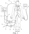
- an extracorporeal blood oxygenation circuit 100 is shown connected to a circulation system 20 of a patient 10.
- the circulation system 20 is a human (or animal) circulatory system including blood, a vascular system, and a heart.
- the circulation system 20 is includes a cardiopulmonary system 30 and a systemic system connecting the cardiopulmonary system to the tissues of the body.
- the systemic system passes the blood though the vascular system (arteries, veins, and capillaries) throughout the body.
- the cardiopulmonary system 30 includes the right heart, the lungs and the left heart, as well as the vascular structure connecting the right heart to the lungs, the lungs to the left heart and some portion of the aorta and large veins located between the extracorporeal circuit and the right and left heart. That is, in theory the cardiopulmonary system 30 would include only the right heart, the lungs, the left heart and the vascular structure directly connecting the right heart to the lungs and the lungs to the left heart. However, in practice it is sometimes impracticable to operably connect the extracorporeal circuit 100 immediately adjacent the large vein at the right heart. Therefore, the cardiopulmonary system 30 often includes a limited length of the vein entering the right heart. For example, the extracorporeal circuit 100 can be connected to a femoral vein, thereby effectively extending the cardiopulmonary system 30 to such femoral vein.
- the term "upstream" of a given position refers to a direction against the flow of blood, and the term “downstream” of a given position is the direction of blood flow away from the given position.
- the "arterial” side or portion is that part in which oxygenated blood flows from the heart to the capillaries.
- the "venous” side or portion is that part in which blood flows from the capillaries to the heart and lungs (to the cardiopulmonary system 30).
- the basic components of the extracorporeal circuit 100 for a conventional extracorporeal oxygenation machine include an access (or venous) line 110, an oxygenator 120 and heat exchanger (not shown), a pump 130, a return (or arterial) 140, a sensor 116 in the venous line, a sensor 146 in the arterial line and a controller 160.
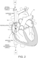
- the extracorporeal circuit 100 is configured to form a veno-venous (W) extracorporeal circuit 100.
- W veno-venous
- the site of the withdrawal of blood from the circulation system 20 to the extracorporeal circuit 100 and the site of introduction of blood from the extracorporeal circuit to the circulation system both occur in the venous portion of the circulation system as seen in Figure 2 .
- the site of withdrawal of blood from the circulation system 20 to the extracorporeal circuit 100 is the inferior vena cava and the site of introduction of blood from the extracorporeal circuit to the circulation system is the superior vena cava.
- the VV extracorporeal circuit 100 withdraws blood from the venous portion of the circulation system 20 (or cardiopulmonary system 30), and returns the blood to the venous portion of the circulation system.
- the withdrawn blood can be treated while it is withdrawn, such as through gas exchange or oxygenation (ECMO) before being returned to the venous portion of the circulation system 20.
- the blood treatment can be any of a variety of treatments including, but not limited to, oxygenation (and carbon dioxide withdrawal).
- the access line 110 withdraws or drains blood from the patient and into the extracorporeal circuit 100.
- the access line 110 extends from the venous portion of the circulation system 20, and preferably from a venous portion of the cardiopulmonary system 30.
- the access line 110 typically includes an access cannula 112 providing the fluid connection to the circulation system 20.
- the access line 110 can also include or provide an introduction site such as an indicator introduction port 114 as the site for introducing an indicator into the extra corporeal circuit 100.
- an introduction site such as an indicator introduction port 114 as the site for introducing an indicator into the extra corporeal circuit 100.
- the indicator introduction port 114 for introducing the dilution indicator is upstream to an inlet of the oxygenator 120.
- the introduction site 114 can be integrated into the oxygenator 120.
- the senor 116 can be a dilution sensor for sensing passage of the indicator through the extracorporeal circuit 100.
- the dilution sensor 116 (as well as sensor 146) can be any of a variety of sensors, and can cooperate with the particular indicator.
- the sensor 116 (as well as sensor 146) can measure different blood properties: such as but not limited to temperature, Doppler frequency, electrical impedance, optical properties, density, ultrasound velocity, concentration of glucose, oxygen saturation and other blood substances (any physical, electrical or chemical blood properties). It is also understood the sensor 116 can also measure the blood flow rate. Alternatively, there can a separate flow sensor (not shown) in addition to sensor 116 be to measure the blood flow rate.
- the present system includes a single blood property sensor and a single flow rate sensor. It is further contemplated that a single combined sensor for measuring flow rate and a blood parameter (property) can be used. As set forth herein, in some pumps 130, a rotational speed, RPM (rotations per minute) of the pump can be measured for providing a measurement of blood flow rate.
- RPM rotational speed
- the return line 140 connects the extracorporeal circuit 100 to a venous portion of the circulation system 20 and in one configuration to a venous portion of the cardiopulmonary system 30.
- the return line 140 usually connects to the superior vena cava but may connected to right atria (tip position ) or inferior vena cava.
- the return line 140 typically includes a return (arterial) cannula 142 providing the fluid connection to the circulation system 20.
- the return line 140 can also include a sensor such as the sensor 146.
- the sensor 146 can be any of a variety of sensors, as set forth in the description of the sensor 116, and is typically selected to cooperate with the anticipated indicator.
- the sensors 116, 146 can be located outside of the extracorporeal circuit. That is, the sensors 116, 146 can be remotely located and measure in the extracorporeal circuit 100, the changes produced in the blood from the indicator introduction or values related to the indicator introduction which can be transmitted or transferred by means of diffusion, electro-magnetic or thermal fields or by other means to the location of the sensor.
- two sensors are shown, it is understood only a single sensor is necessary in order to measure a recirculation. While use of two sensors can improve accuracy, it is not necessary that two sensors be employed to calculate recirculation.
- the oxygenator 120 can be broadly classified into bubble type oxygenators and membrane type oxygenators.
- the membrane type oxygenators fall under the laminate type, the coil type, and the hollow fiber type.
- Membrane type oxygenators offer advantages over the bubble type oxygenators as the membrane type oxygenators typically cause less blood damage, such as hemolysis, protein denaturation, and blood coagulation as compared with the bubble type oxygenators.
- the preferred configuration is set forth in terms of a membrane type oxygenator, it is understood any type of oxygenator can be employed.
- the pump 130 can be any of a variety of pumps types, including but not limited to a peristaltic or roller (or impeller or centrifugal) pump.
- the pump 130 induces a blood flow rate through the extracorporeal circuit 100.
- the pump 130 can be directly controlled at the pump or can be controlled through the controller 160 to establish a given blood flow rate in the extracorporeal circuit 100.
- the pump 130 can be at any of a variety of locations in the extracorporeal circuit 100, and is not limited to the position shown in the Figures.
- the pump 130 is a commercially available pump and can be set or adjusted to provide any of a variety of flow rates, wherein the flow rate can be read by a user and/or transmitted to and read by the controller 160.
- the controller 160 is typically connectable to the oxygenator 120, the pump 130 and the sensor(s) 116, 146.
- the controller 160 can be a stand-alone device such as a personal computer, a dedicated device or embedded in one of the components, such as the pump 130 or the oxygenator 120.
- the controller 160 is shown as connected to the sensors 116 and 146, the pump 130 and the oxygenator 120, it is understood the controller can be connected to only the sensors, the sensors or the pump, or any combination of the sensors, the pump and the oxygenator.
- at least one of the pump 130 and the controller 160 provides for control of the pump and the flow rate of the blood through the pump, respectively.
- the controller 160 also can be connected to the oximeter to automatically collect data or oximetry data can be put manually into controller. Alternatively, a pulse oximeter 60 and the controller 160 can be integrated as a single unit.
- the controller 160 is programmed with the equations as set forth herein and can perform the associated calculations based on inputs from the user and/or connected components.
- the normal or forward blood flow through the extracorporeal circuit 100 includes withdrawing blood through the access line 110 from the venous side of the circulation system 20 (and particularly the cardiopulmonary circuit 30), passing the withdrawn blood through the extracorporeal circuit (to treat such as oxygenate), and introducing the withdrawn (or treated or oxygenated) blood through the return line 140 into the venous side of the circulation system.
- the pump 130 thereby induces a blood flow at a known (measured) blood flow rate through the extracorporeal circuit 100 from the access line 110 to the return line 140.
- Cardiac output CO is the amount of blood pumped out by the left ventricle in a given period of time (typically a 1 minute interval).
- the heart capacity (flow) is typically measured by cardiac output CO.
- the term blood flow rate means a rate of blood passage, volume per unit time.
- the blood flow rate is a volumetric flow rate ("flow rate").
- the volumetric flow rate is a measure of a volume of liquid passing a cross-sectional area of a conduit per unit time, and may be expressed in units such as milliliters per min (ml/min) or liters per minute (l/min).
- the present disclosure provides a simple noninvasive technology to measure cardiac output, CO in VV extracorporeal blood oxygenation, such as a VV ECMO setting.
- VV extracorporeal blood oxygenation such as a VV ECMO setting.
- venous oxygen saturation measured pre-oxygenator in the extracorporeal (ECMO) circuit 100 may be different from mixed venous oxygen saturation in the cardiopulmonary system 30 - as well as being subject to influence from the presence of any recirculation.
- Equation 4 can be used with the measured and reliable values of Q b and SaO 2 in conjunction with a measured SvO 2 , such as measured in the access line 110, recognizing the measured surrogate value of SvO 2 value may introduce an unacceptable error in certain instances, especially in the case of the presence of recirculation.
- Equation 4 For low maintenance in the value of measured SvO 2 , or the equation can still be used for CO assessment with an acceptable measurement of SvO 2 , but is less accurate.
- a further configuration of the present system can incorporate an accounting of recirculation.
- recirculation is the withdrawal of reinfused oxygenated blood through the access (drainage) cannula 112 without the reinfused oxygenated blood passing through the circulation system 20. Because recirculated blood does not contribute to oxygen delivery in the circulation system 20, the presence of recirculation decreases the efficiency of the extra corporeal blood oxygenation (ECMO) procedure.
- ECMO extra corporeal blood oxygenation
- venous oxygen saturation measured pre-oxygenator in the extracorporeal (ECMO) circuit 100 will differ even more from the mixed venous oxygen saturation in the presence of recirculation.
- SvO 2 at the inlet of the blood oxygenator 120 (ECMO) one needs to use the following equation:
- SvO 2 in the venous vessel may be used in Eq. 4B instead of SvO 2 , but this substitution will result in an error in the calculated CO from substitution of the mixed venous oxygen saturation by the oxygen saturation from the vessels where the oxygen saturation was sampled.
- the value of Q b (such as via flow rate of the pump 130 in the extracorporeal circuit 100) can be changed, such as by an increase or decrease to deliver a different flow rate of 100% oxygenated blood through the return line 140 and into the heart.
- ⁇ SaO 2 SaO 2 1 ⁇ SaO 2 2
- index "(1)" and "(2)" correspond to a first flow rate delivered by the extracorporeal circuit 100, such as a first pump setting, Q b(1) and a second flow rate delivered by the extracorporeal circuit, such as a second pump setting pump setting Q b(2) , respectively.
- Equations 11-12 and Equations 11A-12A are independent of (eliminates) the need for assumptions of the venous oxygen saturations in Eq.4 (A, B) instead of a mix venous oxygen saturation.
- the CO of the patient on extracorporeal blood oxygenation such as VV-ECMO can be obtained in the following configurations.
- the patient, and particularly the circulation system 20 is operably connected to the extracorporeal circuit 100, wherein the access line 110, which can include the cannula (an access cannula) 112 as known in the art, withdraws blood from the patient, and particularly the venous portion of the circulation system 20 and in one configuration from the inferior vena cava.
- the access line 110 which can include the cannula (an access cannula) 112 as known in the art, withdraws blood from the patient, and particularly the venous portion of the circulation system 20 and in one configuration from the inferior vena cava.
- the withdrawn blood is passed through the access line 110 through the pump 130 and to the oxygenator 120.
- the blood is oxygenated in the oxygenator 120 and then pumped through the return line 140 for introduction of the oxygenated blood to the patient, and particularly the circulation system 20 and more particularly the venous portion of the circulation system 20, and more particularly the venous side of the cardiopulmonary system 30, such as the superior vena cava.
- amount (flow rate) of oxygenated blood introduced into the circulation system 20 is measured, such as by reading the volumetric pump flow setting of the pump 130.
- alternative mechanisms can be used to measure the flow of oxygenated blood, such as by not limited to, flow meters in the extracorporeal circuit 100, dilution measurements, ultrasonic measurements as known in the art.
- the arterial oxygen saturation, SaO 2 is measured such as by pulse oximetry or arterial blood gas analysis. As seen in Figure 1 , a pulse oximeter 60 is connected to the patient to measure arterial oxygen saturation, SaO 2 .
- the venous oxygen saturation, SvO 2 is measured at the inlet of the oxygenator in the extracorporeal circuit 100. It is understood this measurement is not of mixed venous oxygen saturation, but is rather measurement of a surrogate. However, in view of the invasion nature and potential complications inherent in drawing blood from the pulmonary artery, the measurement of oxygen saturation from the blood drawn from the inferior vena cava is used.
- the method for calculating CO is not limited to the manner of measurement of the parameter upon which the CO is calculated.
- the patient is operably connected to the extracorporeal circuit 100 as set forth above. It is further understood that although the present method is set forth with specific manner of obtaining measurements, any available manner of obtaining the identified data can be employed.
- the amount of oxygenated blood introduced into the patient circulation system 20 is identified by the setting of the pump 130.
- Recirculation, R, and arterial oxygen saturation, SaO 2 are measured, such as set forth above.
- the flow rate of oxygenated blood from the extracorporeal circuit 100 and introduced to the circulation system 20 is then changed by an amount sufficient to generate a corresponding change to the measured SaO 2 .
- the amount of change in the flow rate of oxygenated blood from the extracorporeal circuit 100 is sufficient to impart a change in the measured SaO 2 that is greater than operating error, drift or variance.
- the change in flow rate of oxygenated blood from the extracorporeal circuit 100 is at least 10% of the original flow rate, and in further configurations at least 20% of the original flow rate, an in other configurations at least 30% of the original flow rate. It is understood the change in flow rate of oxygenated blood from the extracorporeal circuit 100 can be as depending on the particular set of circumstances in order to generate the corresponding changes in the blood parameter such as arterial oxygen saturation, without deviating from the present system.
- the change in the flow of oxygenated blood from the extracorporeal circuit 100 to the circulation system 20 can be readily imparted by changing the operation of the pump 130.
- a second flow rate of oxygenated blood is introduced into the circulation system 20.
- Recirculation, R, and arterial oxygen saturation, SaO 2 are measured, such as set forth above, during the second flow rate of oxygenated blood passing into the circulation system 20.
- the CO can then be calculated through Eq. 11 and 12 or Eq. 11A and 12A from the measured first and second flow rate of oxygenated blood introduced into the circulation system 20, and the corresponding recirculation and arterial oxygen saturation, SaO 2 for each flow rate.
- the dilution sensors on the access line 110 and the return line 140 are used in conjunction with the introduction of an indicator, such as saline, at the indicator introduction port 114. Recirculation is then measured from the introduced indicator and measurement of the indicator at the sensors as known in the art.
- an indicator such as saline
- the arterial oxygen saturation, SaO 2 is also measured as set forth above.
- a different second flow rate of oxygenated blood is then imposed in the extracorporeal circuit 100 sufficient to impart a change in at least the arterial oxygen saturation, SaO 2 wherein the measured change is outside operating variances or drift, such as set forth above.
- the pump flow rate of the second flow rate is recorded and the recirculation again measured, such as by the dilution technique.
- Arterial oxygen saturation, SaO 2 is also measured during or corresponding to the second flow rate.
- CO can be determined from Eq. 11 and 12 or Eq. 11A and 12A from the measured first and second flow rate of oxygenated blood introduced into the circulation system 20, and the corresponding recirculation and arterial oxygen saturation, SaO 2 for each flow rate.
- any contribution of oxygenation from the lungs was taken as small (negligible).
- accuracy of the assessment or calculation of CO can be further improved if oxygenation contribution from the lungs are taken into account or estimated.
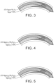
- the first flow is the well oxygenated blood from the extracorporeal circuit 100 and the second flow is the less oxygenated venous (mixed venous) blood from the organs.
- the mixture of these two flows defines the saturation of oxygen in the cardiac output CO.
- Q eff is part of the flow from the extracorporeal circuit (ECMO) flow that enters the heart accounting for recirculation;
- Q eff Q b ⁇ 1 ⁇ R % 100
- CO ⁇ SaO 2 Q eff ⁇ Sa ox O 2 + CO ⁇ Q eff S v O 2 + Res L CO ⁇ Q eff
- a resolution of the single equation and two unknowns is to obtain a second equation, thereby presenting two equations with two unknowns, which can be mathematically solved.
- the extracorporeal circuit flow rate, ECMO flow is changed to present a measurable change in arterial oxygen saturation SaO 2 , which change is greater than normal operating variances or drift.
- index "1" and "2" denote the respective value as related to the first flow rate from the extracorporeal circuit 100 and the second flow rate from the extracorporeal circuit, respectively.
- the change in flow rate in the extracorporeal circuit is taken as Q eff (1) > Q eff(2) . That is, the pump flow can be decreased, thereby decreasing the extracorporeal circuit flow rate.
- Equations 20A and 20B assume that CO does not change during the extracorporeal circuit 100 (pump flow) decrease or the change in CO is negligible. However, there are now two equations and three unknowns: CO, S L O 2(1) and S L O 2(2) . Again, as there are more unknowns than equations, the system of equations cannot be solved directly.
- the next step of the present modeling is to approximate a solution of current system of equations by considering the relationship between S L O 2(1) and S L O 2(2) .
- K ⁇ S v O 2 ⁇ S a O 2
- Equation 24 suggests that even if an actual value of post venous lung oxygen saturation is not known, but the changes of the mixed venous oxygen saturation are known, then the system of equations can be solved.
- Equation 20A and 20B If the value of K is known or estimated, then the system of Equations 20A and 20B can be solved and CO and S L O 2(1) calculated.
- Case 2 where the pre-oxygenator venous oxygen saturation is available, is related to ECMO devices that routinely measure the pre-oxygenator oxygen saturation S VOX O 2 . Also, in some clinics a blood sample is taken to measure pre-oxygenator venous oxygen saturation.
- the controller can be configured to calculate cardiac output based upon equations 1 through 25; and in further configurations, the controller is configured to calculate cardiac output based upon equations 4, 9A, 11, 12, 12A, 19, 20A, 20B, 23 and 24.
- the indicator is any substance that alters a measurable blood property.
- the indicator may alter any measurable parameter of the blood.
- the indicator may be chemical, optical, electrical, thermal or any combination thereof.
- the particular indicator is at least partly dictated by the anticipated operating environment. Available indicators include saline solutions, increased or decreased temperature as well as dyes and various isotopes.
- the use of temperature differentials may be accomplished by locally creating a heat source (such as a heater in the oxygenator 120) or a heat sink in the surrounding flow.
- a heat source such as a heater in the oxygenator 120
- the creation of a local temperature gradient offers the benefit of being able to employ a dilution indicator without introducing any additional volume into the blood flow. That is, a temperature differential may be created without an accompanying introduction of a volume of indicator.
- a volume of heated or cooled blood may be introduced at the indicator introduction port 114 as the indicator.
- a component of the extracorporeal circuit 100 can be controlled to create or induce an indicator within the flow in the extracorporeal circuit. For example, a filtration or treatment rate or heater can be sufficiently changed to create an effective indicator in the extracorporeal circuit 100 which then travels through the cardiopulmonary system 30.
- calculate means determine the amount or number of something mathematically, including to evaluate or estimate the nature, amount or quantity.
- the term measure means how much there is of the relevant parameter, including ascertain the size, amount, or degree of (something) such as by using an instrument or device marked in standard units or by comparing it with an object of known size, wherein the measuring may be of representative or a surrogate value or a surrogate parameter.
- the setting of the pump 130 can be used, a separate flow meter can be used, or dilution measurement can be used. It is further contemplated that measuring can include a calculating step or steps.
- calculate or calculating means to discover or identify a number or an amount using mathematics, a mathematical processes or equations.
- the term surrogate is a parameter which is used as a metric for one or more other parameters. Therefore, for purposes of description, when a specific parameter is recited as measured, it is understood that such measurement includes a representative of the parameter or a surrogate parameter that is measured, without deviating from the present system. Thus, it is understood that measuring a blood flow, recirculation or oxygen saturation encompasses measuring the relevant representative parameter as well as measuring a surrogate parameter. For example, it is understood the oxygen content (which may include contribution from other portions of the blood such as the plasma) can be measured in place of arterial oxygen saturation. Although the present analysis is set forth in terms of oxygen saturation, it is intended that oxygen content can be employed and that the recited oxygen saturation encompasses oxygen saturation as well as oxygen content.
- the present method and equations are set forth in terms of oxygen saturation, it is understood that other parameters and/or gases of the blood can be used in place of the blood oxygen saturation. That is, as soon as blood is pumped by the pump 130 in the extracorporeal circuit 100, there will be different physical/chemical property of the blood than the blood flowing in the veins. For example, if the blood is cooled (or heated) in the oxygenator 120, while the blood temperate flowing in the body is at body temperature, then upon measuring the temperature in the artery, the recorded temperature will be a mixture and the analogous concept of heat balance can be applied.
- a rate of respiration could be changed (decreased or even temporarily halted) to impart a change in a blood parameter to be measured corresponding to the respective blood flows.
- the present system includes providing at least a first and a different second blood flow rate from the extracorporeal circuit 100 wherein a blood parameter is measured on the arterial side of the patient circulation system 20 during or corresponding to the first flow rate and during or corresponding the second flow rate, as well as a recirculation corresponding to each of the first and the second flow rates.
- these values can then be used to calculate CO.
Description
- The present disclosure relates to assessing cardiac output of a patient operably connected to a veno-venous (VV) extracorporeal circuit, and particularly to a veno-venous extracorporeal blood oxygenation circuit such as but not limited to a veno-venous extracorporeal membrane oxygenation (ECMO) circuit.
- VV ECMO is a medical procedure employed in patients who are experiencing life-threatening respiratory failure, typically Acute Respiratory Distress Syndrome (ARDS). However, other indications include infection, such as viral, bacterial, fungus, PCP; primary lung disease, such as cystic fibrosis, hemorrhagic auto immune diseases; idiopathic fibrosis, sickle cell crisis, primary pulmonary hypertension; chest trauma, post pneumonectomy; post-transplant: acute, chronic (bronchiolitis obliterans); chronic respiratory failure bridging to transplant.
- In these patients, blood that is passing the lungs is poorly oxygenated, and thus not enough oxygen is delivered to the tissue. This lack of oxygen delivery causes damage to the tissue and can ultimately the death of the patient. Extracorporeal blood oxygenation, such as VV ECMO, supplements or replaces blood oxygenation by the lungs of the patient.
- In VV ECMO, large cannulas are inserted usually through femoral and/or jugular veins with the tip located in the superior and/or inferior vena cava or in the right atrium. These cannulae are then connected to an extracorporeal circuit which includes a pump and a membrane oxygenator. Blood is usually withdrawn from one (or two locations) and delivered close to the right atria, but there are multiple modifications. The patient blood is continuously circulated through the extracorporeal circuit, by being withdrawn from the patient, then circulated through an oxygenator, such as a membrane oxygenator, where the blood is then oxygenated. The blood is returned to the patient where the now oxygenated blood is pumped by right heart through lungs to left heart which delivers the oxygenated blood to the body tissue.
- An important consequence of VV ECMO treatment is the occurrence of recirculation. Recirculation arises when a portion of the oxygenated blood that is being returned to the patient does not pass into the patient heart but is withdrawn into the extracorporeal circuit. This can occur due to poor positioning of the withdrawal and delivery cannulas, and/or if the patient has insufficient cardiac output to accept the full flow of oxygenated blood. Recirculation can be a problem during treatment, as the presence of recirculation means that some portion of the therapy being supplied to the patient is not actually assisting in their recovery.
- The VV ECMO procedure is usually applied to patients that have a good working heart. During the course of VV ECMO, cardiac insufficiency (often right heart) may develop. This can be a life threatening situation. Sufficiency of circulation by the heart is typically assessed by measuring the cardiac output. Current standard methods to measure cardiac output (CO) such as pulmonary artery thermodilution and transpulmonary thermodilution are invasive as well as often inaccurate. In the VV ECMO setting, these methods may give misleading results, especially at high recirculation levels. As a result, a dramatic heart failure may be missed. An identified decrease in CO can be addressed by physicians either by medication therapy or by moving the patient to VA ECMO, where the extracorporeal circuit provides heart support in addition to lung support (though the VA ECMO is more invasive).
- Document
US2008033314A1 discloses a method for determining cardiac output in conjunction with flow through an extracorporeal circuit, wherein flow through an arterial line of the extracorporeal circuit is temporarily reversed and an indicator is passed through the cardiopulmonary circuit. A dilution curve is measured in the arterial line of the extracorporeal circuit during the reversed flow, and cardiac output is determined corresponding to the measured dilution curve. - An apparatus is provided for calculating cardiac output of a patient undergoing veno-venous extracorporeal oxygenation through a veno-venous extracorporeal circuit, wherein the apparatus includes a controller, a pump connected to the veno-venous extracorporeal circuit for generating a blood flow through the veno-venous extracorporeal circuit, the pump operably connected to the controller and configured to generate a first blood flow rate through the veno-venous extracorporeal circuit and a different second blood flow rate through the veno-venous extracorporeal circuit; an oximeter connected to the controller for measuring a first arterial oxygen saturation corresponding to the first blood flow rate and a second arterial oxygen saturation corresponding to the second blood flow rate, wherein the controller is configured to calculate a cardiac output of the patient corresponding to the first measured arterial oxygen saturation, the second measured arterial oxygen saturation, the first blood flow rate and the second blood flow rate. In a further configuration, the controller is configured to calculate the cardiac output further corresponding to a first amount of recirculation during the first blood flow rate and a second amount of recirculation during the second blood flow rate. The controller can be further configured to adjust the calculated cardiac output by an amount corresponding to a first oxygen saturation of mixed venous blood after passing the lungs during the first blood flow rate and a second oxygen saturation of mixed venous blood after passing the lungs during the second blood flow rate. In one configuration, the controller is configured to adjust the calculated cardiac output by an amount corresponding to a difference between the first measured arterial oxygen saturation and the second measured arterial oxygen saturation. The controller can be further configured to adjust the calculated cardiac output by an amount proportional to a difference between the first measured arterial oxygen saturation and the second measured arterial oxygen saturation.
- The following will describe embodiments of the present disclosure, but it should be appreciated that the present disclosure is not limited to the described embodiments and various modifications of the invention are possible without departing from the basic principles. The scope of the present disclosure is therefore to be determined solely by the appended claims.
-
-
Figure 1 is a representative veno-venous extracorporeal blood oxygenation circuit. -
Figure 2 is representation of the location of blood introduction and blood withdrawal in the veno-venous extracorporeal blood oxygenation circuit. -
Figure 3 is a schematic representation of the components of oxygenation of the blood delivered to the arterial side of a patient circulation system. -
Figure 4 is a schematic representation of the components of oxygenation of the blood delivered to the arterial side of a patient circulation system at a first blood flow rate from the extracorporeal circuit. -
Figure 5 is a schematic representation of the components of oxygenation of the blood delivered to the arterial side of a patient circulation system at a second, smaller, blood flow rate from the extracorporeal circuit. - Referring to
Figure 1 , an extracorporealblood oxygenation circuit 100 is shown connected to acirculation system 20 of apatient 10. - The
circulation system 20 is a human (or animal) circulatory system including blood, a vascular system, and a heart. For purposes of this description, thecirculation system 20 is includes acardiopulmonary system 30 and a systemic system connecting the cardiopulmonary system to the tissues of the body. Specifically, the systemic system passes the blood though the vascular system (arteries, veins, and capillaries) throughout the body. - The
cardiopulmonary system 30 includes the right heart, the lungs and the left heart, as well as the vascular structure connecting the right heart to the lungs, the lungs to the left heart and some portion of the aorta and large veins located between the extracorporeal circuit and the right and left heart. That is, in theory thecardiopulmonary system 30 would include only the right heart, the lungs, the left heart and the vascular structure directly connecting the right heart to the lungs and the lungs to the left heart. However, in practice it is sometimes impracticable to operably connect theextracorporeal circuit 100 immediately adjacent the large vein at the right heart. Therefore, thecardiopulmonary system 30 often includes a limited length of the vein entering the right heart. For example, theextracorporeal circuit 100 can be connected to a femoral vein, thereby effectively extending thecardiopulmonary system 30 to such femoral vein. - For cardiopulmonary and vascular systems, the term "upstream" of a given position refers to a direction against the flow of blood, and the term "downstream" of a given position is the direction of blood flow away from the given position. The "arterial" side or portion is that part in which oxygenated blood flows from the heart to the capillaries. The "venous" side or portion is that part in which blood flows from the capillaries to the heart and lungs (to the cardiopulmonary system 30).
- The basic components of the
extracorporeal circuit 100 for a conventional extracorporeal oxygenation machine include an access (or venous)line 110, anoxygenator 120 and heat exchanger (not shown), apump 130, a return (or arterial) 140, asensor 116 in the venous line, asensor 146 in the arterial line and acontroller 160. - The
extracorporeal circuit 100 is configured to form a veno-venous (W)extracorporeal circuit 100. In the veno-venousextracorporeal circuit 100, the site of the withdrawal of blood from thecirculation system 20 to theextracorporeal circuit 100 and the site of introduction of blood from the extracorporeal circuit to the circulation system both occur in the venous portion of the circulation system as seen inFigure 2 . - Referring to
Figure 2 , in one configuration, the site of withdrawal of blood from thecirculation system 20 to theextracorporeal circuit 100 is the inferior vena cava and the site of introduction of blood from the extracorporeal circuit to the circulation system is the superior vena cava. - Thus, the VV
extracorporeal circuit 100 withdraws blood from the venous portion of the circulation system 20 (or cardiopulmonary system 30), and returns the blood to the venous portion of the circulation system. The withdrawn blood can be treated while it is withdrawn, such as through gas exchange or oxygenation (ECMO) before being returned to the venous portion of thecirculation system 20. The blood treatment can be any of a variety of treatments including, but not limited to, oxygenation (and carbon dioxide withdrawal). - Generally, the
access line 110 withdraws or drains blood from the patient and into theextracorporeal circuit 100. Theaccess line 110 extends from the venous portion of thecirculation system 20, and preferably from a venous portion of thecardiopulmonary system 30. Referring toFigure 2 , theaccess line 110 typically includes anaccess cannula 112 providing the fluid connection to thecirculation system 20. - The
access line 110 can also include or provide an introduction site such as anindicator introduction port 114 as the site for introducing an indicator into the extracorporeal circuit 100. In one configuration, theindicator introduction port 114 for introducing the dilution indicator is upstream to an inlet of theoxygenator 120. In selected configurations, theintroduction site 114 can be integrated into theoxygenator 120. - In the
access line 110, thesensor 116, can be a dilution sensor for sensing passage of the indicator through theextracorporeal circuit 100. However, it is understood, the dilution sensor 116 (as well as sensor 146) can be any of a variety of sensors, and can cooperate with the particular indicator. The sensor 116 (as well as sensor 146) can measure different blood properties: such as but not limited to temperature, Doppler frequency, electrical impedance, optical properties, density, ultrasound velocity, concentration of glucose, oxygen saturation and other blood substances (any physical, electrical or chemical blood properties). It is also understood thesensor 116 can also measure the blood flow rate. Alternatively, there can a separate flow sensor (not shown) in addition tosensor 116 be to measure the blood flow rate. Thus, in one configuration the present system includes a single blood property sensor and a single flow rate sensor. It is further contemplated that a single combined sensor for measuring flow rate and a blood parameter (property) can be used. As set forth herein, in somepumps 130, a rotational speed, RPM (rotations per minute) of the pump can be measured for providing a measurement of blood flow rate. - The
return line 140 connects theextracorporeal circuit 100 to a venous portion of thecirculation system 20 and in one configuration to a venous portion of thecardiopulmonary system 30. Thereturn line 140 usually connects to the superior vena cava but may connected to right atria (tip position ) or inferior vena cava. Thereturn line 140 typically includes a return (arterial) cannula 142 providing the fluid connection to thecirculation system 20. - The
return line 140 can also include a sensor such as thesensor 146. Thesensor 146 can be any of a variety of sensors, as set forth in the description of thesensor 116, and is typically selected to cooperate with the anticipated indicator. - However, it is understood the
sensors sensors extracorporeal circuit 100, the changes produced in the blood from the indicator introduction or values related to the indicator introduction which can be transmitted or transferred by means of diffusion, electro-magnetic or thermal fields or by other means to the location of the sensor. Although two sensors are shown, it is understood only a single sensor is necessary in order to measure a recirculation. While use of two sensors can improve accuracy, it is not necessary that two sensors be employed to calculate recirculation. - The
oxygenator 120 can be broadly classified into bubble type oxygenators and membrane type oxygenators. The membrane type oxygenators fall under the laminate type, the coil type, and the hollow fiber type. Membrane type oxygenators offer advantages over the bubble type oxygenators as the membrane type oxygenators typically cause less blood damage, such as hemolysis, protein denaturation, and blood coagulation as compared with the bubble type oxygenators. Although the preferred configuration is set forth in terms of a membrane type oxygenator, it is understood any type of oxygenator can be employed. - The
pump 130 can be any of a variety of pumps types, including but not limited to a peristaltic or roller (or impeller or centrifugal) pump. Thepump 130 induces a blood flow rate through theextracorporeal circuit 100. Depending on the specific configuration, thepump 130 can be directly controlled at the pump or can be controlled through thecontroller 160 to establish a given blood flow rate in theextracorporeal circuit 100. Thepump 130 can be at any of a variety of locations in theextracorporeal circuit 100, and is not limited to the position shown in the Figures. In one configuration, thepump 130 is a commercially available pump and can be set or adjusted to provide any of a variety of flow rates, wherein the flow rate can be read by a user and/or transmitted to and read by thecontroller 160. - The
controller 160 is typically connectable to theoxygenator 120, thepump 130 and the sensor(s) 116, 146. Thecontroller 160 can be a stand-alone device such as a personal computer, a dedicated device or embedded in one of the components, such as thepump 130 or theoxygenator 120. Although thecontroller 160 is shown as connected to thesensors pump 130 and theoxygenator 120, it is understood the controller can be connected to only the sensors, the sensors or the pump, or any combination of the sensors, the pump and the oxygenator. In one configuration, at least one of thepump 130 and thecontroller 160 provides for control of the pump and the flow rate of the blood through the pump, respectively. It is also understood, thecontroller 160 also can be connected to the oximeter to automatically collect data or oximetry data can be put manually into controller. Alternatively, apulse oximeter 60 and thecontroller 160 can be integrated as a single unit. - The
controller 160 is programmed with the equations as set forth herein and can perform the associated calculations based on inputs from the user and/or connected components. - The normal or forward blood flow through the
extracorporeal circuit 100 includes withdrawing blood through theaccess line 110 from the venous side of the circulation system 20 (and particularly the cardiopulmonary circuit 30), passing the withdrawn blood through the extracorporeal circuit (to treat such as oxygenate), and introducing the withdrawn (or treated or oxygenated) blood through thereturn line 140 into the venous side of the circulation system. Thepump 130 thereby induces a blood flow at a known (measured) blood flow rate through theextracorporeal circuit 100 from theaccess line 110 to thereturn line 140. - For purposes of the present description, the following terminology is used. Cardiac output CO is the amount of blood pumped out by the left ventricle in a given period of time (typically a 1 minute interval). The heart capacity (flow) is typically measured by cardiac output CO. The term blood flow rate means a rate of blood passage, volume per unit time. The blood flow rate is a volumetric flow rate ("flow rate"). The volumetric flow rate is a measure of a volume of liquid passing a cross-sectional area of a conduit per unit time, and may be expressed in units such as milliliters per min (ml/min) or liters per minute (l/min).
- The present disclosure provides a simple noninvasive technology to measure cardiac output, CO in VV extracorporeal blood oxygenation, such as a VV ECMO setting. To apply the present technique to measure CO during VV extracorporeal blood oxygenation, including ECMO, the following terms are employed:
- SvO2 is the mixed venous oxygen saturation of blood that did not pass through the
oxygenator 120 - SaOz- arterial oxygen saturation, (which as set forth below can be measured by blood sample or by pulse oximetry)
- Qb is the extracorporeal circuit flow rate, (which as set forth below can be measured by a flow rate of the
pump 130 in the extracorporeal circuit) - R% is the percentage recirculation (%)
- CO is the cardiac output
- In the first instance, a mass balance equation is applied to the extracorporeal circuit. For this analysis, the following assumptions are made:
- 1. Oxygenation in the lungs is small (negligible).
- 2. Oxygen Saturation of the blood after oxygenator is at or near 100%. (The formula below can be adjusted for a different value of oxygen saturation from the oxygenator 120).
- 3. No recirculation.
- With the appropriate accounting for oxygen, an initial equation becomes:

- Solving for CO:


- Currently, during VV ECMO treatment, Qb and SaO2 are routinely measured, while SvO2 is difficult to measure. That is, the value of venous oxygen saturation measured pre-oxygenator in the extracorporeal (ECMO)
circuit 100 may be different from mixed venous oxygen saturation in the cardiopulmonary system 30 - as well as being subject to influence from the presence of any recirculation. - Therefore, Equation 4 can be used with the measured and reliable values of Qb and SaO2 in conjunction with a measured SvO2, such as measured in the
access line 110, recognizing the measured surrogate value of SvO2 value may introduce an unacceptable error in certain instances, especially in the case of the presence of recirculation. - Thus, depending on the confidence in the SvO2 value, there are 2 unknowns in Equation 4 for low maintenance in the value of measured SvO2, or the equation can still be used for CO assessment with an acceptable measurement of SvO2, but is less accurate.
- A further configuration of the present system can incorporate an accounting of recirculation. Referring to
Figure 2 , in veno-venous extracorporeal blood oxygenation, such as VV ECMO, recirculation is the withdrawal of reinfused oxygenated blood through the access (drainage)cannula 112 without the reinfused oxygenated blood passing through thecirculation system 20. Because recirculated blood does not contribute to oxygen delivery in thecirculation system 20, the presence of recirculation decreases the efficiency of the extra corporeal blood oxygenation (ECMO) procedure. - In case of recirculation, the actual effective flow, Qeff, that carries 100% oxygenated blood into heart will be:

- Replacing Qb with Qeff in Equation 4, yields:

- Substituting Qb for Qeff provides:

- The value of venous oxygen saturation measured pre-oxygenator in the extracorporeal (ECMO)
circuit 100 will differ even more from the mixed venous oxygen saturation in the presence of recirculation. Thus, to use measured SvO2 at the inlet of the blood oxygenator 120 (ECMO), one needs to use the following equation: - Taking the oxygen saturation balance at the inflow of oxygenator:

- Where Equation 8 can be rewritten as:

- Which simplifies to:

- The value of SvO2 in the venous vessel may be used in Eq. 4B instead of SvO2, but this substitution will result in an error in the calculated CO from substitution of the mixed venous oxygen saturation by the oxygen saturation from the vessels where the oxygen saturation was sampled.
- To increase the accuracy of the CO measurement with the purpose of the elimination of the potentially unreliable or unknown value of SvO2, the value of Qb (such as via flow rate of the
pump 130 in the extracorporeal circuit 100) can be changed, such as by an increase or decrease to deliver a different flow rate of 100% oxygenated blood through thereturn line 140 and into the heart. - For purposes of description, assume the flow of oxygenated blood from the oxygenator is decreased, such as by decreasing pump flow (where Qb(2) < Qb(1)). Thus, less 100% oxygenated blood is delivered from the
extracorporeal circuit 100 and measured on the arterial side of the patient, SaO2 (2) < SaO2 (1). From this difference, a change in SaO2, ΔSaO2, can be written as:

where index "(1)" and "(2)" correspond to a first flow rate delivered by theextracorporeal circuit 100, such as a first pump setting, Qb(1) and a second flow rate delivered by the extracorporeal circuit, such as a second pump setting pump setting Qb(2), respectively. - For this application of two balance equations analogous to Eq. 4B, it is assumed the value of CO between the two flows through the
extracorporeal circuit 100 does not change or that any actual change is insubstantial or negligible. Thus, the two equations for the two different flow rates of oxygenated blood from theextracorporeal circuit 100 are:

- It can be seen that in case of no recirculation, these equations will be analogous to Eq. 4.
- During the decrease in SaO2 from SaO2(1) to SaO2(2), a decrease of SvO2 is also expected. However, the magnitude of this decrease in SvO2 is unknown. If the magnitude of the decrease in SaO2 is small, then the assumption is made that SvO 2(1) ≈ SvO 2(2), then the system of equations (Eq. 11 and Eq. 12) with 2 unknowns (CO and SvO2) can be solved for CO, which in turn can then be calculated from the known or measured Qb(1), Qb(2), %R(1) and %R(2), SaO2(1) and SaO2(2), without relying upon a value of SvO2.
- For example, if the magnitude of the decrease in SaO2 is small, then the assumption is made that SvO 2(1) ≈ SvO 2(2), and the system of equations (Eq. 11 and Eq. 12) provide:


- Further, if recirculation were not measured and the magnitude of the decrease in SaO2 is small, then the assumption is made that SvO2(1) ≈ SvO2(2), then the system of equations (Eq. 11 and Eq. 12) provide:


- Conversely, if the decrease of SvO2(1) is as large as the decrease of arterial oxygen saturation, ΔSaO2, (Eq. 10) then ΔSvO2 = ΔSaO2, or:

- From this equation, SvO2(2) can be calculated as:

- Substituting the above in to Eq.11 and 12 gives:


- Again, a system of two equations with 2 unknowns (CO and SvOz) is provided, wherein the equations can be solved to determine CO, without requiring a value or measurement of SvO2.
- Theoretically, it is believed the actual CO will be between value calculated from Equations 11-12 and the value calculated from Equations 11A-12A. Practically, it is observed that after a decrease of arterial oxygen saturation, the venous oxygen saturation also decreases. Thus, the CO value provided by Equations 11A-12A should be more accurate.
- In case of the lungs partly working (thereby partly oxygenating the blood) the actual mass balance equations need to include an after lung oxygen saturation instead of venous oxygen saturation. The benefit of the current two flow rate approach is that it is independent of (eliminates) the need for assumptions of the venous oxygen saturations in Eq.4 (A, B) instead of a mix venous oxygen saturation. In addition, there may be intermediate conditions (assumptions) applied to Equations 11-12 and Equations 11A-12A, like the assumption that SvO2(2) does not decrease the entire amount of decrease in SaO2 as per ΔSaO2, but on a portion such as 1/3 or 1/5 etc., then all the solutions for the CO value will be between Equations 11-12 and Equations 11A-12A.
- In application, the CO of the patient on extracorporeal blood oxygenation, such as VV-ECMO can be obtained in the following configurations.
- In one configuration, the patient, and particularly the
circulation system 20, is operably connected to theextracorporeal circuit 100, wherein theaccess line 110, which can include the cannula (an access cannula) 112 as known in the art, withdraws blood from the patient, and particularly the venous portion of thecirculation system 20 and in one configuration from the inferior vena cava. - The withdrawn blood is passed through the
access line 110 through thepump 130 and to theoxygenator 120. The blood is oxygenated in theoxygenator 120 and then pumped through thereturn line 140 for introduction of the oxygenated blood to the patient, and particularly thecirculation system 20 and more particularly the venous portion of thecirculation system 20, and more particularly the venous side of thecardiopulmonary system 30, such as the superior vena cava. - To calculate the CO, amount (flow rate) of oxygenated blood introduced into the
circulation system 20 is measured, such as by reading the volumetric pump flow setting of thepump 130. However, it is understood alternative mechanisms can be used to measure the flow of oxygenated blood, such as by not limited to, flow meters in theextracorporeal circuit 100, dilution measurements, ultrasonic measurements as known in the art. - The arterial oxygen saturation, SaO2, is measured such as by pulse oximetry or arterial blood gas analysis. As seen in
Figure 1 , apulse oximeter 60 is connected to the patient to measure arterial oxygen saturation, SaO2. - The venous oxygen saturation, SvO2, is measured at the inlet of the oxygenator in the
extracorporeal circuit 100. It is understood this measurement is not of mixed venous oxygen saturation, but is rather measurement of a surrogate. However, in view of the invasion nature and potential complications inherent in drawing blood from the pulmonary artery, the measurement of oxygen saturation from the blood drawn from the inferior vena cava is used. - It is noted that the method for calculating CO is not limited to the manner of measurement of the parameter upon which the CO is calculated.
- Then assuming no, or negligible recirculation, the CO is calculated by:

- The recirculation can also be measured by any of the following mechanisms known in the art:
Method of estimating % recirculation Description CVL (Central Venous Line) Formula: (SpreO2- SvO2)/(SpostO2-SvO2) x100 SvO2 estimated by measuring venous oxygen saturation of blood from SVC (superior vena cava) or IVC (inferior vena cava) via central venous catheter SvO2 Formula: (SpreO2 - SvO2)/(SpostO2 - SvO2) x100 SvO2 = SpreO2 when sweep gas turned off and ventilator used to achieve an equivalent SaO2 Ultrasound dilution#12 Saline injected into reinfusion limb; ultrasound sensor detects differences in dilution between drainage and reinfusion limb Thermodilution Cold saline injected into reinfusion limb; thermistor-tipped catheter detects changes in temperature in drainage limb Trending SpreO2 Observation of changes in SpreO2 and SaO2 over time; increasing SpreO2 and decreasing SaO2 suggest clinically relevant recirculation - where CVL = central venous line
- ECMO = extracorporeal membrane oxygenation
- IVC = inferior vena cava
- SVC = superior vena cava
- SaO2 = oxygen saturation of arterial blood
- SpreO2 = oxygen saturation of blood entering the membrane oxygenator
- SpostO2 = oxygen saturation of blood leaving the membrane oxygenator
- SvO2 = oxygen saturation of venous blood returning to the vena cava
- Thus, as set forth above to accommodate the presence of recirculation, Eq. 4B is used.

- In an alternative configuration employing select equations from above, the patient is operably connected to the
extracorporeal circuit 100 as set forth above. It is further understood that although the present method is set forth with specific manner of obtaining measurements, any available manner of obtaining the identified data can be employed. - In this alternative configuration, the amount of oxygenated blood introduced into the
patient circulation system 20 is identified by the setting of thepump 130. Recirculation, R, and arterial oxygen saturation, SaO2, are measured, such as set forth above. - The flow rate of oxygenated blood from the
extracorporeal circuit 100 and introduced to thecirculation system 20 is then changed by an amount sufficient to generate a corresponding change to the measured SaO2. Further, in one configuration the amount of change in the flow rate of oxygenated blood from theextracorporeal circuit 100 is sufficient to impart a change in the measured SaO2 that is greater than operating error, drift or variance. In some configurations, the change in flow rate of oxygenated blood from theextracorporeal circuit 100 is at least 10% of the original flow rate, and in further configurations at least 20% of the original flow rate, an in other configurations at least 30% of the original flow rate. It is understood the change in flow rate of oxygenated blood from theextracorporeal circuit 100 can be as depending on the particular set of circumstances in order to generate the corresponding changes in the blood parameter such as arterial oxygen saturation, without deviating from the present system. - The change in the flow of oxygenated blood from the
extracorporeal circuit 100 to thecirculation system 20 can be readily imparted by changing the operation of thepump 130. Thus, a second flow rate of oxygenated blood is introduced into thecirculation system 20. - After changing the oxygenated blood flow rate of the
extracorporeal circuit 100, approximately 1 minute to 2 minutes can elapse before measuring the arterial oxygen saturation and the recirculation corresponding to the second flow rate. - Recirculation, R, and arterial oxygen saturation, SaO2, are measured, such as set forth above, during the second flow rate of oxygenated blood passing into the
circulation system 20. - Of note, there is no need for a measurement of SvO2 or a surrogate parameter in this configuration. The CO can then be calculated through Eq. 11 and 12 or Eq. 11A and 12A from the measured first and second flow rate of oxygenated blood introduced into the
circulation system 20, and the corresponding recirculation and arterial oxygen saturation, SaO2 for each flow rate. - In a further configuration, the dilution sensors on the
access line 110 and thereturn line 140 are used in conjunction with the introduction of an indicator, such as saline, at theindicator introduction port 114. Recirculation is then measured from the introduced indicator and measurement of the indicator at the sensors as known in the art. - The arterial oxygen saturation, SaO2, is also measured as set forth above.
- A different second flow rate of oxygenated blood is then imposed in the
extracorporeal circuit 100 sufficient to impart a change in at least the arterial oxygen saturation, SaO2 wherein the measured change is outside operating variances or drift, such as set forth above. - The pump flow rate of the second flow rate is recorded and the recirculation again measured, such as by the dilution technique. Arterial oxygen saturation, SaO2 is also measured during or corresponding to the second flow rate.
- Again, CO can be determined from Eq. 11 and 12 or Eq. 11A and 12A from the measured first and second flow rate of oxygenated blood introduced into the
circulation system 20, and the corresponding recirculation and arterial oxygen saturation, SaO2 for each flow rate. - As set forth in the above analysis, any contribution of oxygenation from the lungs was taken as small (negligible). However, accuracy of the assessment or calculation of CO can be further improved if oxygenation contribution from the lungs are taken into account or estimated.
- It can be assumed that there is a combination of two flows passing through
cardiopulmonary system 30. The first flow is the well oxygenated blood from theextracorporeal circuit 100 and the second flow is the less oxygenated venous (mixed venous) blood from the organs. The mixture of these two flows defines the saturation of oxygen in the cardiac output CO. For the pulmonary artery, the following two component equation provides a mass balance for oxygen saturation carried by hemoglobin in VV ECMO:

- Where Qeff is part of the flow from the extracorporeal circuit (ECMO) flow that enters the heart accounting for recirculation;
- SaoxO2 is the oxygen saturation of blood after the oxygenator 120 (approximately 100%);
- CO is the cardiac output;
- SvO2 is the mixed venous oxygen saturation of blood entering the right atrium from the veins (not passed through oxygenator 120); and
- SPAO2 is the oxygen saturation of blood in the pulmonary artery.
- As set forth above Qeff is defined as

- where Qb is the extracorporeal circuit flow rate; and
- R% is the percentage recirculation.
- Assuming the lungs are partially functioning, then the balance equation becomes:

- where ResL is the oxygen added by the lungs; and
- SaO2 is the arterial oxygen saturation.
- The venous and lung function can then be associated as follows:

- Then,

where SLO2 is the oxygen saturation of mixed venous blood after passing the lungs. - Finally, the mass balance equation for oxygen saturation across the whole
cardiopulmonary system 30 will be:

- As shown in Eq. 19, there is a sense where one can think of the lungs only changing the oxygen saturation of the venous portion of the blood as the blood after oxygenator is already 100% oxygen saturated. While in fact, as seen in
Fig. 3 , the oxygenated blood from the lungs acting on the mixture is a useful concept for the purpose of analyzing Eq. 19. - In Eq. 19, and referring to
Fig. 3 , the values of SaO2, and Qeff can be measured if recirculation is measured, but the values of CO and SLO2 are unknown. Thus, there is one equation with two unknowns. - In an effort to reduce the number of unknowns relative to the number of equations, a second equation is generated as set forth below.
- A resolution of the single equation and two unknowns is to obtain a second equation, thereby presenting two equations with two unknowns, which can be mathematically solved. To produce the second equation, the extracorporeal circuit flow rate, ECMO flow, is changed to present a measurable change in arterial oxygen saturation SaO2, which change is greater than normal operating variances or drift.
- While the change in extracorporeal circuit flow rate could be an increase or decrease, for purposes of description, a decrease is employed so as to generate a corresponding decrease in the arterial oxygen saturation ΔSaO2. This decrease in the arterial oxygen saturation is due to less of flow of the 100% saturated blood component coming from the
oxygenator 120 and more flow of the less oxygenated mixed venous blood component coming from organs, as seen inFigures 4 and 5 . This change in extracorporeal flow rate creates a second mass balance equation. - Thus, from Eq. 19,


- In the two equation system, 20A and 20B, index "1" and "2" denote the respective value as related to the first flow rate from the
extracorporeal circuit 100 and the second flow rate from the extracorporeal circuit, respectively. As set forth above, for purposes of description the change in flow rate in the extracorporeal circuit is taken as Qeff (1) > Qeff(2). That is, the pump flow can be decreased, thereby decreasing the extracorporeal circuit flow rate. - Equations 20A and 20B assume that CO does not change during the extracorporeal circuit 100 (pump flow) decrease or the change in CO is negligible. However, there are now two equations and three unknowns: CO, SLO2(1) and SLO2(2). Again, as there are more unknowns than equations, the system of equations cannot be solved directly.
- The next step of the present modeling is to approximate a solution of current system of equations by considering the relationship between SLO2(1) and SLO2(2).
- In response to the arterial oxygen saturation SaO2 decrease, it is expected that mixed venous oxygen saturation SvO2 also may change, which can be expressed as:

- Then assuming that during the arterial oxygen saturation decrease, the residual lung function does not change or only changes negligibly, then the following equation can be produced from Eq. 18 and Eq. 21:

- For simplicity, a coefficient K is introduced as the then ratio of changes in the mixed venous oxygen saturation to the changes in the arterial oxygen saturation:

- Then, Eq. 22 can be rewritten based on Eq. 23:

- Alternatively, Eq. 24 can be written as:

- Equation 24 suggests that even if an actual value of post venous lung oxygen saturation is not known, but the changes of the mixed venous oxygen saturation are known, then the system of equations can be solved.
- If the value of K is known or estimated, then the system of Equations 20A and 20B can be solved and CO and SLO2(1) calculated.
- However, it is recognized that the mathematical modeling of errors from uncertainty of the venous oxygen saturation will change in response to the decrease in arterial oxygen saturation.
- The errors produced by any unknown changes in venous oxygen saturation in response to the decrease in arterial oxygen saturation may be mathematically analyzed for two possible cases:
-
Case 1. Pre-oxygenator venous oxygen saturation is not available. -
Case 2. Pre-oxygenator venous oxygen saturation is available. -
Case 2, where the pre-oxygenator venous oxygen saturation is available, is related to ECMO devices that routinely measure the pre-oxygenator oxygen saturation SVOXO2. Also, in some clinics a blood sample is taken to measure pre-oxygenator venous oxygen saturation. A true value of oxygen saturation of venous blood in central vein SvO2(W) can be estimated from the oxygen saturation of blood entering oxygenator 120 SVOXO2%, if recirculation is known:

- While it is not certain how accurately oxygen saturation of withdrawn blood SvO2(w) represents the mixed SvO2 in equation 21, its dynamic changes may help to make a choice for direction/magnitude of changes in K in Eq. 24.
- Therefore, the controller can be configured to calculate cardiac output based upon
equations 1 through 25; and in further configurations, the controller is configured to calculate cardiac output based upon equations 4, 9A, 11, 12, 12A, 19, 20A, 20B, 23 and 24. - It is understood the indicator is any substance that alters a measurable blood property. The indicator may alter any measurable parameter of the blood. For example, the indicator may be chemical, optical, electrical, thermal or any combination thereof. The particular indicator is at least partly dictated by the anticipated operating environment. Available indicators include saline solutions, increased or decreased temperature as well as dyes and various isotopes. The use of temperature differentials may be accomplished by locally creating a heat source (such as a heater in the oxygenator 120) or a heat sink in the surrounding flow. The creation of a local temperature gradient offers the benefit of being able to employ a dilution indicator without introducing any additional volume into the blood flow. That is, a temperature differential may be created without an accompanying introduction of a volume of indicator. Alternatively, a volume of heated or cooled blood may be introduced at the
indicator introduction port 114 as the indicator. It is also contemplated, that a component of theextracorporeal circuit 100 can be controlled to create or induce an indicator within the flow in the extracorporeal circuit. For example, a filtration or treatment rate or heater can be sufficiently changed to create an effective indicator in theextracorporeal circuit 100 which then travels through thecardiopulmonary system 30. - For purposes of description, the term calculate (or calculating) means determine the amount or number of something mathematically, including to evaluate or estimate the nature, amount or quantity.
- For purposes of description, the term measure (or measuring) means how much there is of the relevant parameter, including ascertain the size, amount, or degree of (something) such as by using an instrument or device marked in standard units or by comparing it with an object of known size, wherein the measuring may be of representative or a surrogate value or a surrogate parameter. For example, for measuring the oxygenated blood flow rate introduced into the
patient circulation system 20, the setting of thepump 130 can be used, a separate flow meter can be used, or dilution measurement can be used. It is further contemplated that measuring can include a calculating step or steps. - As used herein, the term calculate or calculating means to discover or identify a number or an amount using mathematics, a mathematical processes or equations.
- As used herein, the term surrogate is a parameter which is used as a metric for one or more other parameters. Therefore, for purposes of description, when a specific parameter is recited as measured, it is understood that such measurement includes a representative of the parameter or a surrogate parameter that is measured, without deviating from the present system. Thus, it is understood that measuring a blood flow, recirculation or oxygen saturation encompasses measuring the relevant representative parameter as well as measuring a surrogate parameter. For example, it is understood the oxygen content (which may include contribution from other portions of the blood such as the plasma) can be measured in place of arterial oxygen saturation. Although the present analysis is set forth in terms of oxygen saturation, it is intended that oxygen content can be employed and that the recited oxygen saturation encompasses oxygen saturation as well as oxygen content.
- Although the present method and equations are set forth in terms of oxygen saturation, it is understood that other parameters and/or gases of the blood can be used in place of the blood oxygen saturation. That is, as soon as blood is pumped by the
pump 130 in theextracorporeal circuit 100, there will be different physical/chemical property of the blood than the blood flowing in the veins. For example, if the blood is cooled (or heated) in theoxygenator 120, while the blood temperate flowing in the body is at body temperature, then upon measuring the temperature in the artery, the recorded temperature will be a mixture and the analogous concept of heat balance can be applied. - It is further contemplated that if the patient were also on a ventilator, a rate of respiration could be changed (decreased or even temporarily halted) to impart a change in a blood parameter to be measured corresponding to the respective blood flows.
- Thus, in one configuration, the present system includes providing at least a first and a different second blood flow rate from the
extracorporeal circuit 100 wherein a blood parameter is measured on the arterial side of thepatient circulation system 20 during or corresponding to the first flow rate and during or corresponding the second flow rate, as well as a recirculation corresponding to each of the first and the second flow rates. As set forth above in the equations, these values can then be used to calculate CO. - This disclosure has been described in detail with particular reference to an embodiment, but it will be understood that variations and modifications can be effected within the scope of the disclosure. The presently disclosed embodiments are therefore considered in all respects to be illustrative and not restrictive. The scope of the invention is indicated by the appended claims, and all changes that come within the meaning and range of equivalents thereof are intended to be embraced therein.
Claims (5)
- An apparatus for calculating cardiac output of a patient undergoing veno-venous extracorporeal oxygenation through a veno-venous extracorporeal circuit (100), comprising:a controller (160); anda pump (130) connected to the veno-venous extracorporeal circuit (100) for generating a blood flow through the veno-venous extracorporeal circuit (100);characterized by an oximeter (60);wherein the pump (130) is operably connected to the controller (160) and configured to generate a first blood flow rate through the veno-venous extracorporeal circuit (100) and a different second blood flow rate through the veno-venous extracorporeal circuit (100);wherein the oximeter (60) is connected to the controller (160) for measuring a first arterial oxygen saturation corresponding to the first blood flow rate and a second arterial oxygen saturation corresponding to the second blood flow rate; andwherein the controller (160) is configured to calculate a cardiac output of the patient corresponding to the first measured arterial oxygen saturation, the second measured arterial oxygen saturation, the first blood flow rate and the second blood flow rate.
- The apparatus of claim 1, wherein the controller (160) is configured to calculate the cardiac output further corresponding to a first amount of recirculation during the first blood flow rate and a second amount of recirculation during the second blood flow rate.
- The apparatus of claim 1 or 2, wherein the controller (160) is configured to adjust the calculated cardiac output by an amount corresponding to a first oxygen saturation of mixed venous blood after passing the lungs during the first blood flow rate and a second oxygen saturation of mixed venous blood after passing the lungs during the second blood flow rate.
- The apparatus of any one of claims 1 to 3, wherein the controller (160) is configured to adjust the calculated cardiac output by an amount corresponding to a difference between the first measured arterial oxygen saturation and the second measured arterial oxygen saturation.
- The apparatus of any one of claims 1 to 4, wherein the controller (160) is further configured to adjust the calculated cardiac output by an amount proportional to a difference between the first measured arterial oxygen saturation and the second measured arterial oxygen saturation.
Applications Claiming Priority (2)
| Application Number | Priority Date | Filing Date | Title |
|---|---|---|---|
| US201962796800P | 2019-01-25 | 2019-01-25 | |
| PCT/US2020/015016 WO2020154638A1 (en) | 2019-01-25 | 2020-01-24 | Method and apparatus for assessing cardiac output in veno-venous extracorporeal blood oxygenation |
Publications (3)
| Publication Number | Publication Date |
|---|---|
| EP3914316A1 EP3914316A1 (en) | 2021-12-01 |
| EP3914316A4 EP3914316A4 (en) | 2022-05-04 |
| EP3914316B1 true EP3914316B1 (en) | 2023-03-08 |
Family
ID=71733144
Family Applications (1)
| Application Number | Title | Priority Date | Filing Date |
|---|---|---|---|
| EP20744707.9A Active EP3914316B1 (en) | 2019-01-25 | 2020-01-24 | Apparatus for assessing cardiac output in veno-venous extracorporeal blood oxygenation |
Country Status (4)
| Country | Link |
|---|---|
| US (2) | US11439735B2 (en) |
| EP (1) | EP3914316B1 (en) |
| JP (2) | JP7278648B2 (en) |
| WO (1) | WO2020154638A1 (en) |
Families Citing this family (4)
| Publication number | Priority date | Publication date | Assignee | Title |
|---|---|---|---|---|
| US11633525B2 (en) | 2019-01-29 | 2023-04-25 | Transonic Systems Inc. | Method and apparatus for assessing cardiac output in veno-arterial extracorporeal blood oxygenation |
| EP3962550A4 (en) | 2019-05-02 | 2023-02-01 | Transonic Systems Inc. | Calculating cardiac output of a patient undergoing veno-venous extracorporeal blood oxygenation |
| US20210393941A1 (en) * | 2020-06-17 | 2021-12-23 | Tc1 Llc | Extracorporeal blood pump assembly and methods of assembling same |
| US20230277740A1 (en) * | 2022-03-01 | 2023-09-07 | Transonic Systems Inc. | Method and apparatus for measurement of an ultrafiltration rate in a renal replacement therapy device |
Family Cites Families (12)
| Publication number | Priority date | Publication date | Assignee | Title |
|---|---|---|---|---|
| US5685989A (en) * | 1994-09-16 | 1997-11-11 | Transonic Systems, Inc. | Method and apparatus to measure blood flow and recirculation in hemodialysis shunts |
| US6090061A (en) * | 1997-10-22 | 2000-07-18 | In-Line Diagnostics Corporation | Disposable extracorporeal conduit for blood constituent monitoring |
| AT407960B (en) | 1997-09-22 | 2001-07-25 | Mohl Werner Ddr | DEVICE FOR SUPPORTING THE PERFORMANCE OF A HEART |
| US6718190B2 (en) | 1997-10-14 | 2004-04-06 | Transonic Systems, Inc. | Sensor calibration and blood volume determination |
| US6155984A (en) * | 1999-04-15 | 2000-12-05 | Transonic Systems, Inc. | Method and apparatus for measuring cardiac output through an arterial cannula |
| US7261696B2 (en) * | 2004-09-09 | 2007-08-28 | Transonic Systems, Inc. | Method and apparatus for measuring cardiac output via an extracorporeal cardiopulmonary support circuit |
| WO2006096758A2 (en) * | 2005-03-07 | 2006-09-14 | Transonic Systems, Inc. | System and method for determining cardiac output |
| US20100057046A1 (en) * | 2008-09-03 | 2010-03-04 | Keimar, Inc | Systems for characterizing physiologic parameters and methods for use therewith |
| DE102012018628A1 (en) * | 2012-09-21 | 2014-03-27 | Fresenius Medical Care Deutschland Gmbh | Apparatus and method for detecting recirculation during extracorporeal blood treatment |
| US20150316404A1 (en) * | 2014-05-02 | 2015-11-05 | Transonic Systems, Inc. | Measurement of fluid volume of a blood oxygenator in an extracorporeal circuit |
| EP3302252B1 (en) * | 2015-05-30 | 2020-07-29 | Cardioflow Technologies, LLC | Systems for optimizing intra-cardiac filling pressures through controlled regurgitation |
| EP3478334B1 (en) * | 2016-06-30 | 2020-03-25 | Gambro Lundia AB | Connection test for blood treatment machines ii |
-
2020
- 2020-01-24 JP JP2021543159A patent/JP7278648B2/en active Active
- 2020-01-24 EP EP20744707.9A patent/EP3914316B1/en active Active
- 2020-01-24 US US16/752,035 patent/US11439735B2/en active Active
- 2020-01-24 WO PCT/US2020/015016 patent/WO2020154638A1/en unknown
-
2022
- 2022-08-31 US US17/900,424 patent/US20220409791A1/en active Pending
- 2022-11-10 JP JP2022180169A patent/JP2023017953A/en active Pending
Also Published As
| Publication number | Publication date |
|---|---|
| EP3914316A1 (en) | 2021-12-01 |
| US20200237989A1 (en) | 2020-07-30 |
| EP3914316A4 (en) | 2022-05-04 |
| JP7278648B2 (en) | 2023-05-22 |
| JP2023017953A (en) | 2023-02-07 |
| US20220409791A1 (en) | 2022-12-29 |
| US11439735B2 (en) | 2022-09-13 |
| JP2022523674A (en) | 2022-04-26 |
| WO2020154638A1 (en) | 2020-07-30 |
Similar Documents
| Publication | Publication Date | Title |
|---|---|---|
| EP3914316B1 (en) | Apparatus for assessing cardiac output in veno-venous extracorporeal blood oxygenation | |
| US20230211060A1 (en) | Method and apparatus for assessing cardiac output in veno-arterial extracorporeal blood oxygenation | |
| US20230248887A1 (en) | Calculating cardiac output of a patient undergoing veno-venous extracorporeal blood oxygenation | |
| US6210591B1 (en) | Method to measure blood flow rate in hemodialysis shunts | |
| Depner et al. | Hemodialysis access recirculation measured by ultrasound dilution | |
| US7097630B2 (en) | Method and apparatus for determining hemodialysis parameters | |
| US7815852B2 (en) | Method, apparatus and software program for measurement of a parameter relating to a heart-lung system of a mammal | |
| US20110004141A1 (en) | Method and arrangement for determining the recirculation in a fistula or the cardiopulmonary recirculation, and a blood treatment device comprising a device for determining the fistula recirculation or the cardiopulmonary recirculation part | |
| US20080033314A1 (en) | Method for measuring cardiac output via an extracorporeal cardiopulmonary support circuit | |
| JPH09173444A (en) | Method for operating device for hemotherapy for determining blood flow dynamical parameter during extra-corporeal hemotherapy and device for determining blood flow dynimical parameter during extra-corporeal hemotherapy | |
| US20130317378A1 (en) | Assessment of Pulmonary Blood Flow and Systemic Blood Flow in a Single Ventricle Patient | |
| Taylor | Measurement of the cardiac output in man | |
| JP4909982B2 (en) | System for determining cardiac output | |
| US20220280705A1 (en) | Method and apparatus employing an extracorporeal blood oxygenation circuit blood flow characteristic for quantitatively assessing a physiological parameter of a connected patient | |
| US9375159B2 (en) | Device for indicator dilution measurements | |
| Bellancini | Development and Validation of a CO2 Sensor for Extra Corporeal Life Support Applications | |
| CN113226167A (en) | System, computer system and computer program for determining cardiovascular parameters | |
| Maynar et al. | Lithium dilution cardiac output and arterial pulse power analysis | |
| Schneditz | Extracorporeal sensing techniques | |
| SIMPSON | Monitoring During Anesthesia for Cardiac Surgery |
Legal Events
| Date | Code | Title | Description |
|---|---|---|---|
| STAA | Information on the status of an ep patent application or granted ep patent |
Free format text: STATUS: THE INTERNATIONAL PUBLICATION HAS BEEN MADE |
|
| PUAI | Public reference made under article 153(3) epc to a published international application that has entered the european phase |
Free format text: ORIGINAL CODE: 0009012 |
|
| STAA | Information on the status of an ep patent application or granted ep patent |
Free format text: STATUS: REQUEST FOR EXAMINATION WAS MADE |
|
| 17P | Request for examination filed |
Effective date: 20210824 |
|
| AK | Designated contracting states |
Kind code of ref document: A1 Designated state(s): AL AT BE BG CH CY CZ DE DK EE ES FI FR GB GR HR HU IE IS IT LI LT LU LV MC MK MT NL NO PL PT RO RS SE SI SK SM TR |
|
| A4 | Supplementary search report drawn up and despatched |
Effective date: 20220407 |
|
| DAV | Request for validation of the european patent (deleted) | ||
| DAX | Request for extension of the european patent (deleted) | ||
| RIC1 | Information provided on ipc code assigned before grant |
Ipc: A61B 5/00 20060101ALI20220401BHEP Ipc: A61B 5/145 20060101ALI20220401BHEP Ipc: A61B 5/1455 20060101ALI20220401BHEP Ipc: A61B 5/029 20060101ALI20220401BHEP Ipc: A61M 1/36 20060101ALI20220401BHEP Ipc: A61M 1/16 20060101AFI20220401BHEP |
|
| RIC1 | Information provided on ipc code assigned before grant |
Ipc: A61B 5/00 20060101ALI20220630BHEP Ipc: A61B 5/145 20060101ALI20220630BHEP Ipc: A61B 5/1455 20060101ALI20220630BHEP Ipc: A61B 5/029 20060101ALI20220630BHEP Ipc: A61M 1/36 20060101ALI20220630BHEP Ipc: A61M 1/16 20060101AFI20220630BHEP |
|
| GRAP | Despatch of communication of intention to grant a patent |
Free format text: ORIGINAL CODE: EPIDOSNIGR1 |
|
| STAA | Information on the status of an ep patent application or granted ep patent |
Free format text: STATUS: GRANT OF PATENT IS INTENDED |
|
| INTG | Intention to grant announced |
Effective date: 20220915 |
|
| GRAS | Grant fee paid |
Free format text: ORIGINAL CODE: EPIDOSNIGR3 |
|
| GRAA | (expected) grant |
Free format text: ORIGINAL CODE: 0009210 |
|
| STAA | Information on the status of an ep patent application or granted ep patent |
Free format text: STATUS: THE PATENT HAS BEEN GRANTED |
|
| AK | Designated contracting states |
Kind code of ref document: B1 Designated state(s): AL AT BE BG CH CY CZ DE DK EE ES FI FR GB GR HR HU IE IS IT LI LT LU LV MC MK MT NL NO PL PT RO RS SE SI SK SM TR |
|
| REG | Reference to a national code |
Ref country code: CH Ref legal event code: EP Ref country code: AT Ref legal event code: REF Ref document number: 1552145 Country of ref document: AT Kind code of ref document: T Effective date: 20230315 |
|
| REG | Reference to a national code |
Ref country code: IE Ref legal event code: FG4D |
|
| REG | Reference to a national code |
Ref country code: DE Ref legal event code: R096 Ref document number: 602020008758 Country of ref document: DE |
|
| REG | Reference to a national code |
Ref country code: SE Ref legal event code: TRGR |
|
| REG | Reference to a national code |
Ref country code: LT Ref legal event code: MG9D |
|
| REG | Reference to a national code |
Ref country code: NL Ref legal event code: MP Effective date: 20230308 |
|
| PG25 | Lapsed in a contracting state [announced via postgrant information from national office to epo] |
Ref country code: RS Free format text: LAPSE BECAUSE OF FAILURE TO SUBMIT A TRANSLATION OF THE DESCRIPTION OR TO PAY THE FEE WITHIN THE PRESCRIBED TIME-LIMIT Effective date: 20230308 Ref country code: NO Free format text: LAPSE BECAUSE OF FAILURE TO SUBMIT A TRANSLATION OF THE DESCRIPTION OR TO PAY THE FEE WITHIN THE PRESCRIBED TIME-LIMIT Effective date: 20230608 Ref country code: LV Free format text: LAPSE BECAUSE OF FAILURE TO SUBMIT A TRANSLATION OF THE DESCRIPTION OR TO PAY THE FEE WITHIN THE PRESCRIBED TIME-LIMIT Effective date: 20230308 Ref country code: LT Free format text: LAPSE BECAUSE OF FAILURE TO SUBMIT A TRANSLATION OF THE DESCRIPTION OR TO PAY THE FEE WITHIN THE PRESCRIBED TIME-LIMIT Effective date: 20230308 Ref country code: HR Free format text: LAPSE BECAUSE OF FAILURE TO SUBMIT A TRANSLATION OF THE DESCRIPTION OR TO PAY THE FEE WITHIN THE PRESCRIBED TIME-LIMIT Effective date: 20230308 Ref country code: ES Free format text: LAPSE BECAUSE OF FAILURE TO SUBMIT A TRANSLATION OF THE DESCRIPTION OR TO PAY THE FEE WITHIN THE PRESCRIBED TIME-LIMIT Effective date: 20230308 |
|
| REG | Reference to a national code |
Ref country code: AT Ref legal event code: MK05 Ref document number: 1552145 Country of ref document: AT Kind code of ref document: T Effective date: 20230308 |
|
| PG25 | Lapsed in a contracting state [announced via postgrant information from national office to epo] |
Ref country code: NL Free format text: LAPSE BECAUSE OF FAILURE TO SUBMIT A TRANSLATION OF THE DESCRIPTION OR TO PAY THE FEE WITHIN THE PRESCRIBED TIME-LIMIT Effective date: 20230308 Ref country code: GR Free format text: LAPSE BECAUSE OF FAILURE TO SUBMIT A TRANSLATION OF THE DESCRIPTION OR TO PAY THE FEE WITHIN THE PRESCRIBED TIME-LIMIT Effective date: 20230609 Ref country code: FI Free format text: LAPSE BECAUSE OF FAILURE TO SUBMIT A TRANSLATION OF THE DESCRIPTION OR TO PAY THE FEE WITHIN THE PRESCRIBED TIME-LIMIT Effective date: 20230308 |
|
| PG25 | Lapsed in a contracting state [announced via postgrant information from national office to epo] |
Ref country code: SM Free format text: LAPSE BECAUSE OF FAILURE TO SUBMIT A TRANSLATION OF THE DESCRIPTION OR TO PAY THE FEE WITHIN THE PRESCRIBED TIME-LIMIT Effective date: 20230308 Ref country code: RO Free format text: LAPSE BECAUSE OF FAILURE TO SUBMIT A TRANSLATION OF THE DESCRIPTION OR TO PAY THE FEE WITHIN THE PRESCRIBED TIME-LIMIT Effective date: 20230308 Ref country code: PT Free format text: LAPSE BECAUSE OF FAILURE TO SUBMIT A TRANSLATION OF THE DESCRIPTION OR TO PAY THE FEE WITHIN THE PRESCRIBED TIME-LIMIT Effective date: 20230710 Ref country code: EE Free format text: LAPSE BECAUSE OF FAILURE TO SUBMIT A TRANSLATION OF THE DESCRIPTION OR TO PAY THE FEE WITHIN THE PRESCRIBED TIME-LIMIT Effective date: 20230308 Ref country code: CZ Free format text: LAPSE BECAUSE OF FAILURE TO SUBMIT A TRANSLATION OF THE DESCRIPTION OR TO PAY THE FEE WITHIN THE PRESCRIBED TIME-LIMIT Effective date: 20230308 Ref country code: AT Free format text: LAPSE BECAUSE OF FAILURE TO SUBMIT A TRANSLATION OF THE DESCRIPTION OR TO PAY THE FEE WITHIN THE PRESCRIBED TIME-LIMIT Effective date: 20230308 |
|
| PG25 | Lapsed in a contracting state [announced via postgrant information from national office to epo] |
Ref country code: SK Free format text: LAPSE BECAUSE OF FAILURE TO SUBMIT A TRANSLATION OF THE DESCRIPTION OR TO PAY THE FEE WITHIN THE PRESCRIBED TIME-LIMIT Effective date: 20230308 Ref country code: PL Free format text: LAPSE BECAUSE OF FAILURE TO SUBMIT A TRANSLATION OF THE DESCRIPTION OR TO PAY THE FEE WITHIN THE PRESCRIBED TIME-LIMIT Effective date: 20230308 Ref country code: IS Free format text: LAPSE BECAUSE OF FAILURE TO SUBMIT A TRANSLATION OF THE DESCRIPTION OR TO PAY THE FEE WITHIN THE PRESCRIBED TIME-LIMIT Effective date: 20230708 |
|
| REG | Reference to a national code |
Ref country code: DE Ref legal event code: R097 Ref document number: 602020008758 Country of ref document: DE |
|
| PLBE | No opposition filed within time limit |
Free format text: ORIGINAL CODE: 0009261 |
|
| STAA | Information on the status of an ep patent application or granted ep patent |
Free format text: STATUS: NO OPPOSITION FILED WITHIN TIME LIMIT |
|
| PG25 | Lapsed in a contracting state [announced via postgrant information from national office to epo] |
Ref country code: SI Free format text: LAPSE BECAUSE OF FAILURE TO SUBMIT A TRANSLATION OF THE DESCRIPTION OR TO PAY THE FEE WITHIN THE PRESCRIBED TIME-LIMIT Effective date: 20230308 Ref country code: DK Free format text: LAPSE BECAUSE OF FAILURE TO SUBMIT A TRANSLATION OF THE DESCRIPTION OR TO PAY THE FEE WITHIN THE PRESCRIBED TIME-LIMIT Effective date: 20230308 |
|
| 26N | No opposition filed |
Effective date: 20231211 |
|
| PGFP | Annual fee paid to national office [announced via postgrant information from national office to epo] |
Ref country code: IE Payment date: 20240109 Year of fee payment: 5 |