EP3913970A1 - Transmission of handover information in handover report - Google Patents
Transmission of handover information in handover report Download PDFInfo
- Publication number
- EP3913970A1 EP3913970A1 EP20175844.8A EP20175844A EP3913970A1 EP 3913970 A1 EP3913970 A1 EP 3913970A1 EP 20175844 A EP20175844 A EP 20175844A EP 3913970 A1 EP3913970 A1 EP 3913970A1
- Authority
- EP
- European Patent Office
- Prior art keywords
- handover
- node
- information
- source
- target
- Prior art date
- Legal status (The legal status is an assumption and is not a legal conclusion. Google has not performed a legal analysis and makes no representation as to the accuracy of the status listed.)
- Granted
Links
Images



Classifications
-
- H—ELECTRICITY
- H04—ELECTRIC COMMUNICATION TECHNIQUE
- H04W—WIRELESS COMMUNICATION NETWORKS
- H04W36/00—Hand-off or reselection arrangements
- H04W36/0005—Control or signalling for completing the hand-off
- H04W36/0055—Transmission or use of information for re-establishing the radio link
- H04W36/0079—Transmission or use of information for re-establishing the radio link in case of hand-off failure or rejection
Definitions
- Various example embodiments relate to an apparatus comprising at least one processor.
- Wireless communications systems may e.g. be used for wireless exchange of information between two or more entities such as a user equipment and a network node, e.g. base station.
- Handover procedures may be used e.g. in wireless communication systems for user equipment changing from a currently serving cell provided by a source node to a new cell provided by a target node.
- Some embodiments relate to an apparatus, comprising at least one processor, and at least one memory storing instructions, the at least one memory and the instructions configured to, with the at least one processor, cause a first node to transmit a handover information, which characterizes a type of a handover performed by a user equipment (UE) from a source node to a target node, to at least one of: a) the source node, b) the target node, c) a further entity.
- this may enable e.g. a network comprising the first node to distinguish mobility failure events associated with different handover procedures and/or to provide separate mobility failure counters for different handover types, e.g. for each handover type.
- using the mobility failure counters for different handover types, e.g. for each handover type, the network and/or a component thereof may adjust the mobility parameters associated with a specific handover procedure.
- the apparatus may be an apparatus for a wireless communications system.
- the apparatus or its functionality, respectively, may be provided in a network element of the communications systems, for example in a base station, e.g. a gNodeB (gNB).
- a base station e.g. a gNodeB (gNB).
- gNB gNodeB
- the apparatus according to the embodiments or its functionality, respectively may be used for or within wireless communications systems, e.g. networks, based on or at least partially adhering to third generation partnership project, 3GPP, radio standards such as 4G E-UTRAN, 5G NR (fifth generation new radio) or other radio access technology.
- 3GPP third generation partnership project
- radio standards such as 4G E-UTRAN, 5G NR (fifth generation new radio) or other radio access technology.
- the apparatus according to the embodiments or its functionality, respectively may be used for handover procedures of 5G NR-based communications systems.
- the handover information may be provided within a handover report or handover report message transmitted by the first node, e.g. within a handover report message based on 3GPP TS 36.423, cf. e.g. V16.0.0 (2019-12), chapter 9.1.2.19.
- an information element may be provided to carry the handover information.
- this IE may e.g. be indicated by one or more bits, e.g. two bits in some embodiments.
- the IE for carrying the handover information may be indicated using an ENUM data type.
- the further entity which may be provided with the handover information, may e.g. be a central or centralized entity, for example a trace collection entity, e.g. residing in the network.
- the further entity may be configured to perform mobility robustness optimization (MRO) procedures and/or machine learning (ML)-based optimization.
- MRO mobility robustness optimization
- ML machine learning
- an interface between a radio access network (RAN) and the further entity (e.g., trace collection entity) as specified in 3GPP TS 32.441 and/or TS 32.442 and/or TS 32.421 may be used.
- MRO procedures which e.g. aim at reducing a number of connection failures, e.g. comprising of Radio Link Failure (RLF) and handover failures (HOFs), in the network, may be performed based on the handover information.
- MRO procedures may adjust one or more mobility parameters based on statistics that are collected from the network and/or from UEs, the statistics e.g. comprising the handover type.
- 3GPP TS 32.425 [Section 4.3.1.3.3] and 3GPP TS 36.300 [22.4.2.2] distinguish between the following three types of failures that may be relevant for MRO according to some embodiments:
- 5G NR Rel. 15 has specified a baseline handover (BHO) procedure which is similar to that defined for LTE system [TS 36.300].
- BHO baseline handover
- new handover procedures are specified to improve mobility robustness or/and mobility interruption time:
- the handover type is one of the following elements: a) BHO, b) CHO, c) DAPS, d) a combination of CHO and DAPS.
- the first node may notify at least one of the source node of the handover, the target node of the handover, a further entity such as e.g. a central entity, for example a trace collection entity e.g. residing in the network, about the type of handover used by the UE.
- an information element may be provided to carry the handover information.
- this IE may e.g. be indicated by one or more bits, e.g. two bits in some embodiments, wherein e.g. "00" indicates BHO, "01” indicates CHO, wherein “10” indicates DAPS, and wherein "11" indicates "CHO and DAPS".
- the instructions when executed by the at least one processor, further cause the first node to transmit the handover information upon a radio link failure (RLF) of the user equipment that has occurred after the handover (HO).
- RLF radio link failure
- the first node may be configured to determine whether a RLF has occurred after the HO, e.g. within a predetermined time window after the HO, e.g. by receiving an RLF indication from another node.
- the RLF indication may comprise the handover information.
- the information about the handover type is available at the target node as the UE context is not deleted once it receives the RLF indication.
- the first node is the target node of the handover.
- the first node is a further node, e.g. not the target node of the handover.
- the further node may be a node the UE (re-)connects to after experiencing an RLF after the handover from the source node to the target node.
- a UE may complete a successful handover from a source cell A (or a source node providing the source cell A, respectively) to a target cell B (or a target node providing the target cell B, respectively). Shortly after, the UE may detect an RLF and may re-establish a connection to source cell A or to a new cell C (e.g. provided by a further node, e.g. the further node exemplarily mentioned above). According to some embodiments, such an RLF may be classified as TEH/HWC if the RLF happened shortly after the handover from the source cell A to the cell B (e.g., within 3 seconds).
- this handover may be considered as a too-late-handover (TLH) from cell B to cell C.
- TH too-late-handover
- the failed cell B may be considered as the originator of the failure and may correct its configuration, and in the former case, it would be the source cell A of the previous handover.
- the source cell A can check as well to which mobility group, e.g. (1) slow or fast UE or (2) UEs in different slices, etc.) the failed UE belongs to.
- the grouping is implementation specific and transparent to the target cell.
- the mobility information may be useful if source cell A applies different mobility parameters or strategy for different groups of UEs.
- the mobility information is included by source cell A in the handover request to target cell B which is then stored by target B with the UE context. Note that the source cell typically deletes the UE context after the handover is completed [TS 36.300].
- the source cell can know the handover cause which can be either "Handover Desirable for Radio Reasons", “Time Critical Handover”, “Resource Optimization Handover”, etc...[see 9.2.6 of TS 36.423].
- Some embodiments may at least temporarily address at least one of the following aspects and/or issues: in case of TEH or HWC, the source cell/ or further, e.g. central, entity receiving the handover report may adjust the mobility parameters such that the handover may be triggered later. However, in 5G NR Rel. 16, the handover can be triggered either using BHO, CHO, DAPS, or CHO & DAPS, where each has its corresponding mobility parameters. Using the existing "Handover Report" message, the source cell/or further, e.g. central, entity can neither distinguish the mobility failure events associated with different handover procedures nor determine which mobility parameters to adjust if it is using more than one handover type for handing over connected UEs.
- the instructions when executed by the at least one processor, further cause the first node to receive the handover information.
- the first node may receive the handover information from the user equipment. According to some embodiments, the first node may receive the handover information from the source node of the HO.
- Some embodiments relate to a method comprising: transmitting, by a first node, a handover information, which characterizes a type of a handover performed by a user equipment from a source node to a target node, to at least one of: a) the source node, b) the target node, c) a further entity.
- Some embodiments relate to an apparatus, comprising at least one processor, and at least one memory storing instructions, the at least one memory and the instructions configured to, with the at least one processor, cause a second node to receive a handover information, which characterizes a type of a handover performed by a user equipment from a source node to a target node.
- the second node is configured to receive the handover information from the first node, e.g. the target node of the HO, e.g. in form of a handover report message as exemplarily mentioned above.
- the instructions when executed by the at least one processor, further cause the second node to transmit the handover information to a or the further entity, e.g. central or centralized entity, e.g. a trace collection entity.
- a or the further entity e.g. central or centralized entity, e.g. a trace collection entity.
- the instructions when executed by the at least one processor, further cause the second node to use the received handover information for controlling an operation of at least the source node, wherein preferably using the received handover information comprises at least one of: a) associate a mobility failure event to a specific handover type (e.g., BHO, CHO, DAPS, combination of CHO and DAPS) indicated by the handover information, b) adjust mobility parameters associated with a handover type indicated by the handover information, c) provide individual counters for mobility failure events associated with different handover procedures having different handover types.
- a specific handover type e.g., BHO, CHO, DAPS, combination of CHO and DAPS
- the second node is the source node of the handover.
- the second node is a or the further entity, e.g. central or centralized entity, e.g. a trace collection entity.
- Some embodiments relate to a method comprising: receiving, by a second node, a handover information, which characterizes a type of a handover performed by a user equipment from a source node to a target node.
- Some embodiments relate to an apparatus, comprising at least one processor, and at least one memory storing instructions, the at least one memory and the instructions configured to, with the at least one processor, cause a user equipment to transmit a handover information, which characterizes a type of a handover performed by the user equipment from a source node to a target node, to at least one further node.
- the UE may transmit the handover information by means of and/or within an RLF report which the UE may send after experiencing an RLF, e.g. after a HO.
- the UE may at least temporarily store the type of a handover, e.g. in the form of the handover information, e.g. upon executing a handover from a source node to a target node.
- the handover information may be propagated back, e.g. from the further node which has been provided with the handover information according to some embodiments, e.g. by means of at least one of: a) an RLF indication comprising the handover information, said RLF indication being transmitted from the further node to the target node, b) a handover report comprising the handover information, the handover report being transmitted from the target node to the source node.
- the UE is configured to delete the stored type of handover and/or handover information, e.g. if at least one of the following conditions is satisfied: a) when the handover fails (e.g., if a timer expires, e.g. a T304 timer), b) when an RLF occurs before the handover is completed.
- the UE is configured to, after the completion of the handover, store the handover information, e.g. for a configurable amount of time. After expiry of this configurable amount of time, the UE may delete the handover information.
- Some embodiments relate to an apparatus, comprising at least one processor, and at least one memory storing instructions, the at least one memory and the instructions configured to, with the at least one processor, cause a source node to transmit a handover information, which characterizes a type of a handover performed by the user equipment from the source node to a target node, to at least one further node.
- Some embodiments relate to a method comprising: transmitting, by a user equipment, a handover information, which characterizes a type of a handover performed by the user equipment from a source node to a target node, to at least one further node.
- Some embodiments relate to a method comprising: transmitting, by a source node, a handover information, which characterizes a type of a handover performed by the user equipment from the source node to a target node, to at least one further node.
- Some embodiments relate to an apparatus comprising means for causing a first node to transmit a handover information, which characterizes a type of a handover performed by a user equipment from a source node to a target node, to at least one of: a) the source node, b) the target node, c) a further entity.
- the means may be configured to cause the first node to perform at least one further step of the embodiments explained above.
- Some embodiments relate to an apparatus comprising means for causing a second node to receive a handover information, which characterizes a type of a handover performed by a user equipment from a source node to a target node.
- the means may be configured to cause the second node to perform at least one further step of the embodiments explained above.
- Some embodiments relate to an apparatus comprising means for causing at least one of a) a user equipment, b) a source node to transmit a handover information, which characterizes a type of a handover performed by the user equipment from a or the source node to a target node, to at least one further node.
- the means may be configured to cause at least one of a) the user equipment, b) the source node to perform at least one further step of the embodiments explained above.
- Some embodiments relate to a communications system comprising at least one apparatus according to the embodiments and, optionally, at least one UE.
- Some embodiments relate to a use of the apparatus according to the embodiments and/or of the method according to the embodiments and/or of the system according to the embodiments for at least one of: a) transmitting the handover information to a source node of a handover, b) transmitting the handover information to a target node of a handover, c) transmitting the handover information to a further node, e.g. other than the source node and the target node, d) distinguishing mobility failure events associated with different HO procedures, e) keeping separate counters for mobility failure events, e.g. associated with different HO procedures, f) identifying mobility parameters corresponding to a specific handover type, g) adjusting one or more mobility parameters based on the handover information.
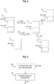
- Fig. 1A schematically depicts a simplified block diagram of the apparatus 100 according to some embodiments
- Fig. 3 schematically depicts a simplified flow chart of a method of operating the apparatus 100 according to some embodiments.
- the apparatus 100 may e.g. be used within the wireless communications system 10 which is exemplarily depicted by Fig. 2 .
- the wireless communications system 10 may comprise a first node 13, a second node 12, and a user equipment (UE) 11.
- the first node 13 may be a target node of a handover HO of the UE 11
- the second node 12 may be a source node of the handover HO of the UE 11.
- the wireless communications system 10 may further comprise at least one further node 13' and/or at least one further entity 14, which are explained in detail further below.
- the apparatus 100 ( Fig. 1A ) comprises at least one processor 102, and at least one memory 104 storing instructions 106 that, when executed by the at least one processor 102, cause the first node 13 ( Fig. 2 ) to, cf. Fig. 3 : transmit 502 a handover information HO-I, which characterizes a type of the handover HO ( Fig. 2 ) performed by the UE 11 from the source node 12 to the target node 13, to at least one of: a) the source node 12, b) the target 13 node (e.g., in cases where the further node 13' is the first node, see further below), c) the further entity 14.
- a handover information HO-I which characterizes a type of the handover HO ( Fig. 2 ) performed by the UE 11 from the source node 12 to the target node 13, to at least one of: a) the source node 12, b) the target 13 node (e.g., in cases where
- the network or system 10 and/or a component 12 thereof may adjust the mobility parameters associated with a specific handover procedure HO, whereby a reliability of the specific handover procedure HO may be increased in some embodiments.
- the apparatus 100 may be provided in a network element or node of the communications systems, for example in the first node 13, which may e.g. be a base station, e.g. a gNodeB (gNB).
- the first node 13 which may e.g. be a base station, e.g. a gNodeB (gNB).
- gNB gNodeB
- the apparatus 100 may be used for or within wireless communications systems 10, e.g. networks, based on or at least partially adhering to third generation partnership project, 3GPP, radio standards such as 4G E-UTRAN, 5G NR (fifth generation new radio) or other radio access technology.
- the apparatus 100 according to the embodiments or its functionality, respectively may be used for handover procedures HO of 5G NR-based communications systems 10.
- the handover information HO-I, cf. Fig. 2, 3 may be provided within a handover report or handover report message transmitted by the first node 13, e.g. within a handover report message based on 3GPP TS 36.423, cf. e.g. V16.0.0 (2019-12), chapter 9.1.2.19 .
- an information element e.g. within the handover report message based on 3GPP TS 36.423, may be provided to carry the handover information HO-I.
- this IE may e.g. be indicated by one or more bits, e.g. two bits in some embodiments.
- the IE for carrying the handover information HO-I may be indicated using an ENUM (enumeration) data type.
- the further entity 14 which may be provided with the handover information HO-I, may e.g. be a central or centralized entity 14, for example a trace collection entity 14, e.g. residing in the network or system 10.
- the further entity 14 may be configured to perform mobility robustness optimization (MRO) procedures and/or machine learning (ML)-based optimization, e.g., based on the handover information HO-I, e.g. to improve a reliability of handovers HO performed by UE within the system 10.
- MRO mobility robustness optimization
- ML machine learning
- an interface (not shown) as specified in 3GPP TS 32.441 and/or TS 32.442 and/or TS 32.421 may be used between a radio access network (RAN) and the further entity 14 (e.g., trace collection entity).
- RAN radio access network
- the further entity 14 e.g., trace collection entity
- MRO procedures which e.g. aim at reducing a number of connection failures, e.g. comprising of Radio Link Failure (RLF) and handover failures (HOFs), in the network or system 10, may be performed based on the handover information HO-I.
- MRO procedures may adjust one or more mobility parameters based on statistics that are collected from the network 10 and/or from UEs 11, the statistics e.g. comprising the handover type.
- 3GPP TS 32.425 [Section 4.3.1.3.3] and 3GPP TS 36.300 [22.4.2.2] distinguish between the following three types of failures that may be relevant for MRO according to some embodiments:
- 5G NR Rel. 15 has specified a baseline handover (BHO) procedure which is similar to that defined for LTE system [TS 36.300].
- BHO baseline handover
- new handover procedures are specified to improve mobility robustness or/and mobility interruption time:
- the handover type is one of the following elements: a) BHO, b) CHO, c) DAPS, d) a combination of CHO and DAPS.
- the first node 13 may notify at least one of the source node 12 of the handover HO and the further entity 14 such as e.g. a central entity, for example a trace collection entity e.g. residing in the network, about the type of handover used by the UE 11.
- an information element may be provided to carry the handover information HO-I.
- this IE may e.g. be indicated by one or more bits, e.g. two bits in some embodiments, wherein e.g. "00" indicates BHO, "01” indicates CHO, wherein “10” indicates DAPS, and wherein "11" indicates "CHO and DAPS".
- the instructions 106 when executed by the at least one processor 102, further cause the first node 13 to transmit 502 ( Fig. 3 ) the handover information HO-I upon a radio link failure (RLF) of the user equipment 11 that has occurred after the handover HO.
- RLF radio link failure
- the first node 13 may be configured to determine 500 ( Fig. 3 ) whether an RLF has occurred after the HO, e.g. within a predetermined time window after the HO, e.g. by receiving an RLF indication RLF-IND from another node.
- the RLF indication RLF-IND may comprise the handover information HO-I.
- the information about the handover type is available at the target node 13 as the UE 11 context is not deleted once it receives the RLF indication RLF-IND.
- the first node 13 is the target node of the handover HO, as already mentioned above.
- the first node is a further node 13', e.g. not the target node 13 of the handover HO.
- the further node 13' may comprise the apparatus 100 or a respective functionality.
- the further node 13' may be a node the UE 11 (re-)connects to after experiencing an RLF after the handover HO from the source node 12 to the target node 13.
- the first node is a (further) node to which the UE 11 re-establishes to or reconnects to after the RLF, or a node that fetches the RLF report from the UE 11.
- the node that fetches the RLF report is not the same as the one that the UE 11 re-establishes to or reconnects to.
- the node that the UE 11 re-establishes to or reconnects to may not fetch the RLF report even though it is available at the UE 11.
- some other node to which the UE 11 may connect to in the future may fetch the RLF report.
- the UE 11 may complete a successful handover HO from a source cell A (or a source node 12 providing the source cell A, respectively) to a target cell B (or a target node 13 providing the target cell B, respectively). Shortly after, the UE 11 may detect an RLF and may re-establish a connection to source cell A or to a new cell C (e.g. provided by a further node, e.g. the further node 13' exemplarily mentioned above).
- a source cell A or a source node 12 providing the source cell A, respectively
- a target cell B or a target node 13 providing the target cell B, respectively.
- the UE 11 may detect an RLF and may re-establish a connection to source cell A or to a new cell C (e.g. provided by a further node, e.g. the further node 13' exemplarily mentioned above).
- such an RLF may be classified as TEH/HWC if the RLF happened shortly after the handover HO from the source cell A (node 12) to the cell B (node 13) (e.g., within 3 seconds). Otherwise, this handover HO may be considered as a too-late-handover (TLH) from cell B (node 13) to cell C (node 13').
- TH too-late-handover
- the failed cell B may be considered as the originator of the failure and may correct its configuration, and in the former case, it would be the source cell A (source node 12) of the previous handover HO.
- the source cell A can check as well to which mobility group, e.g. (1) slow or fast UE or (2) UEs in different slices, etc.) the failed UE belongs to.
- the grouping is implementation specific and transparent to the target cell.
- the mobility information may be useful if source cell A applies different mobility parameters or strategy for different groups of UEs.
- the mobility information is included by source cell A in the handover request to target cell B which is then stored by target B with the UE context. Note that the source cell typically deletes the UE context after the handover is completed [TS 36.300].
- the source cell can know the handover cause which can be either "Handover Desirable for Radio Reasons", “Time Critical Handover”, “Resource Optimization Handover”, etc...[see 9.2.6 of TS 36.423].
- Some embodiments may at least temporarily address at least one of the following aspects and/or issues: in case of TEH or HWC, the source cell or source node 12/ or further, e.g. central, entity 14 receiving the handover report may adjust the mobility parameters such that the handover may be triggered later. However, in 5G NR Rel. 16, the handover can be triggered either using BHO, CHO, DAPS, or CHO & DAPS, where each has its corresponding mobility parameters. Using the existing "Handover Report" message, the source cell/or further, e.g. central, entity can neither distinguish the mobility failure events associated with different handover procedures nor determine which mobility parameters to adjust if it is using more than one handover type for handing over connected UEs.
- the instructions 106 when executed by the at least one processor 102, further cause the first node 13 to receive the handover information HO-I.
- the first node 13 may receive the handover information HO-I from the user equipment 11, which is explained further below with reference to Fig. 8 , 9 .
- the first node 13 may receive the handover information HO-I from the source node 12 of the HO, which is explained further below with reference to Fig. 10 .
- Some embodiments relate to a method, cf. Fig. 3 , comprising: transmitting 502, by the first node 13, 13', a handover information HO-I, which characterizes a type of a handover performed by a user equipment 11 from a source node 12 to a target node 13, to at least one of: a) the source node 12, b) the target node 13 (e.g., in cases where the further node 13' is the first node), c) a further entity 14.
- a handover information HO-I which characterizes a type of a handover performed by a user equipment 11 from a source node 12 to a target node 13, to at least one of: a) the source node 12, b) the target node 13 (e.g., in cases where the further node 13' is the first node), c) a further entity 14.
- cf. Fig. 1B relate to an apparatus 200, comprising at least one processor 202, and at least one memory 204 storing instructions 206, the at least one memory 204 and the instructions 206 configured to, with the at least one processor 202, cause a second node 12 to receive 550 (cf. Fig. 4 ) a handover information HO-I, which characterizes a type of a handover performed by a user equipment 11 from a source node 12 to a target node 13.
- a handover information HO-I which characterizes a type of a handover performed by a user equipment 11 from a source node 12 to a target node 13.
- the second node 12 is configured to receive the handover information HO-I from the first node 13, e.g. the target node of the HO, e.g. in form of a handover report message as exemplarily mentioned above.
- the instructions 206 when executed by the at least one processor 202, further cause the second node 12 to transmit 552 ( Fig. 4 ) the handover information HO-I to a or the further entity 14, e.g. central or centralized entity, e.g. a trace collection entity 14.
- a or the further entity 14 e.g. central or centralized entity, e.g. a trace collection entity 14.
- the instructions 206 when executed by the at least one processor 202, further cause the second node 12 to use 554 ( Fig. 4 ) the received handover information HO-I for controlling an operation of at least the source node 12, wherein preferably using 554 the received handover information HO-I comprises at least one of, cf. Fig.
- a specific handover type e.g., BHO, CHO, DAPS, combination of CHO and DAPS
- the second node is the source node 12 of the handover HO.
- the second node is a or the further entity 14, e.g. central or centralized entity, e.g. a trace collection entity.
- the apparatus 200 of Fig. 1B or its functionality, respectively may e.g. be provided in at least one of the source node 12 ( Fig. 2 ) and the further entity 14.
- Some embodiments, cf. Fig. 4 relate to a method comprising: receiving 550, by a second node 12, 14', a handover information HO-I, which characterizes a type of a handover performed by a user equipment 11 from a source node to a target node.
- a handover information HO-I which characterizes a type of a handover performed by a user equipment 11 from a source node to a target node.
- cf. Fig. 1C relate to an apparatus 300, comprising at least one processor 302, and at least one memory 304 storing instructions 306, the at least one memory 304 and the instructions 306 configured to, with the at least one processor 302, cause a user equipment 11 to transmit a handover information HO-I, cf. step 602 of Fig. 6 , which characterizes a type of a handover performed by the user equipment 11 from a source node 12 to a target node 13, to at least one further node 13'.
- the UE 11 may transmit the handover information HO-I by means of an RLF report which the UE 11 may send after experiencing an RLF, e.g. after re-establishing or reconnecting to a new cell.
- the UE may at least temporarily store the type of a handover, e.g. in the form of the handover information HO-I, e.g. upon executing a handover HO from a source node 12 to a target node 13.
- the optional step 600 of Fig. 6 collectively symbolizes at least one of the following steps that may be performed by the UE 11 according to some embodiments: a) performing a successful handover HO from a source node 12 ( Fig. 2 ) to a target node 13, b) at least temporarily storing the handover information HO-I of the successful handover HO, c) detecting an RLF, e.g. shortly after the successful HO, d) performing a connection re-establishment, e.g. an RRC connection re-establishment, e.g. to a further node 13' or to the source node 12.
- the UE 11 may transmit the handover information HO-I to at least one further node 13', cf. step 602 of Fig. 6 .
- the transmitted handover information HO-I may be propagated back, e.g. from the further node 13' which has been provided with the handover information HO-I by the UE 11 according to some embodiments, e.g. by means of at least one of: a) an RLF indication (not shown in Fig. 6 , explained in detail further below with reference to Fig. 9 ) comprising the handover information HO-I, said RLF indication being transmitted from the further node 13' ( Fig. 2 ) to the target node 12, b) a handover report comprising the handover information HO-I, the handover report being transmitted from the target node 13 to the source node 12.
- the UE 11 is configured to delete the stored type of handover and/or handover information HO-I, e.g. if at least one of the following conditions is satisfied: a) when the handover HO fails (e.g., if a timer expires, e.g. a T304 timer), b) when an RLF occurs before the handover HO is completed.
- the UE 11 is configured to, after the completion of the handover HO, store (cf. step 600 of Fig. 6 ) the handover information HO-I, e.g. for a configurable amount of time. After expiry of this configurable amount of time, the UE 11 may delete the handover information HO-I.
- Some embodiments relate to an apparatus 300, cf. Fig. 1C , comprising at least one processor 302, and at least one memory 304 storing instructions 306, the at least one memory 304 and the instructions 306 configured to, with the at least one processor 302, cause a source node 12 ( Fig. 2 ) to transmit, cf. step 602 of Fig. 6 , a handover information HO-I, which characterizes a type of a handover performed by the user equipment 11 from the source node 12 to a target node 13, to at least one further node, e.g. to the target node 13 and/or to the further entity 14.
- a handover information HO-I which characterizes a type of a handover performed by the user equipment 11 from the source node 12 to a target node 13, to at least one further node, e.g. to the target node 13 and/or to the further entity 14.
- the source node 12 may encode the type of handover, e.g. the handover information HO-I, as a part of the Mobility Information that is sent in a Handover Request (not shown in Fig. 6 , cf. Fig. 9 for further details) to the target node 13.
- the two most significant bits of mobility information may be used to indicate the handover type or handover information HO-I, and the remaining 30 bits out of 32 bits may be used for UE grouping or other purpose.
- the target node 13 may store it and may send it back to the source node 12, e.g. within a Handover Report, e.g. when it receives an RLF indication.
- the apparatus 300 of Fig. 1C or its functionality, respectively may e.g. be provided in at least one of the UE 11 ( Fig. 2 ) and the source node 12.
- Some embodiments, cf. Fig. 6 relate to a method comprising: transmitting 602, by a user equipment 11 ( Fig. 2 ), a handover information HO-I, which characterizes a type of a handover HO performed by the user equipment 11 from a source node 12 to a target node 13, to at least one further node 13'.
- a handover information HO-I which characterizes a type of a handover HO performed by the user equipment 11 from a source node 12 to a target node 13, to at least one further node 13'.
- Some embodiments, cf. Fig. 6 relate to a method comprising: transmitting 602, by a source node 12, a handover information HO-I, which characterizes a type of a handover HO performed by the user equipment 11 from the source node 12 to a target node 13, to at least one further node 13, 14.
- Fig. 7 schematically depicts a simplified flow-chart according to some embodiments.
- the first node 13, 13' receives the handover information HO-I, e.g. from the second node 12, e.g. source node 12.
- the first node 13, 13' transmits the handover information HO-I to at least one of: a) the source node 12, b) the target node 13 (e.g., in case of the first node being the further node 13'), c) the further entity 14.
- Fig. 8 schematically depicts a simplified flow-chart according to some embodiments.
- the elements 11, 12, 13, 13', 14 of Fig. 8 correspond with the elements 11, 12, 13, 13', 14 of Fig. 2 .
- Element e1 of Fig. 8 symbolizes a successful handover HO of the UE 11 from the source node 12 (or its cell “A") to the target node 13 (or its cell “B”).
- Element e2 symbolizes that the UE 11 detects an RLF, e.g. shortly after the successful handover e1.
- Element e3 symbolizes an RRC (Connection) Re-establishment.
- Element e4 symbolizes an RLF indication transmitted from the further node 13' to the target node 13 after the RRC (Connection) Re-establishment e3.
- Element e5 symbolizes that the target node 13 deems or determines that an RLF occurred, e.g. shortly after the handover e1, e.g. based on the RLF indication e4.
- Element e6 symbolizes transmission of the handover information HO-I from the target node 13 to the source node 12, the handover information HO-I e.g. indicating the type of the handover e1.
- the handover information HO-I may be transmitted using a Handover Report message, as explained above.
- Element e7 symbolizes an optional step, wherein the source node 12 associates a mobility failure event with a specific type of the handover e1.
- Element e8 symbolizes an optional step, wherein the source node 12 adjusts one or more mobility parameters associated with the handover type as indicated by the received handover information HO-I, e6.
- Element e9 symbolizes an optional transmission of the handover information HO-I from the target node 13 to the further, e.g. central, entity 14, e.g. in the form of a Handover Report message, as explained above.
- Element e10 symbolizes an optional transmission of the handover information HO-I from the source node 12 to the further, e.g. central, entity 14, e.g. in the form of a Handover Report message, as explained above.
- Element e11 symbolizes an optional step, similar to element e7, wherein the central entity 14 associates a mobility failure event with a specific type of the handover e1.
- Element e12 symbolizes an optional step, similar to element e8, wherein the central entity 14 adjusts one or more mobility parameters associated with the handover type as indicated by the received handover information HO-I, e6.
- the further node 13' may be the same as, i.e. identical with, the source node 12.
- the RRC Connection Re-establishment e3 may be performed with the source node 12, and not with the further node 13'.
- Fig. 9 schematically depicts a simplified flow-chart according to some embodiments.
- the elements 11, 12, 13, 13', 14 of Fig. 9 correspond with the elements 11, 12, 13, 13', 14 of Fig. 2 .
- Element e20 of Fig. 9 symbolizes a successful handover HO of the UE 11 from the source node 12 (or its cell “A") to the target node 13 (or its cell “B”).
- Element e21 symbolizes that the UE 11 at least temporarily stores the type of the handover e20.
- Element e22 symbolizes that the UE detects an RLF, e.g. shortly after the successful handover e20.
- Element e23 symbolizes an RRC (Connection) Re-establishment, e.g. to the further node 13'.
- Element e24 symbolizes an RLF report including the handover information HO-I transmitted from the UE 11 to the further node 13' after the RRC (Connection) Re-establishment e23.
- Element e25 symbolizes an RLF indication, e.g. RLF report, comprising the handover information HO-I, transmitted from the further node 13' to the target node 13.
- Element e26 symbolizes that the target node 13 deems or determines that an RLF occurred, e.g. shortly after the handover e20, e.g. based on the RLF indication e25.
- Element e27 of Fig. 9 similar to element e6 of Fig. 8 , symbolizes transmission of the handover information HO-I from the target node 13 to the source node 12, the handover information HO-I e.g. indicating the type of the handover e20.
- the handover information HO-I may be transmitted using a Handover Report message e27, as explained above.
- Element e28 symbolizes an optional step, wherein the source node 12 associates a mobility failure event with a specific type of the handover e20.
- Element e29 symbolizes an optional step, wherein the source node 12 adjusts one or more mobility parameters associated with the handover type as indicated by the received handover information HO-I, e27.
- Element e30 symbolizes an optional transmission of the handover information HO-I from the further node 13' to the further, e.g. central, entity 14, e.g. in the form of an RLF Report, as explained above.
- Element e31 symbolizes an optional step, similar to element e28, wherein the central entity 14 associates a mobility failure event with a specific type of the handover e20.
- Element e32 symbolizes an optional step, similar to element e29, wherein the central entity 14 adjusts one or more mobility parameters associated with the handover type as indicated by the received handover information HO-I, e30.
- the further node 13' may be the same as, i.e. identical with, the source node 12.
- the RRC Connection Re-establishment e23 may be performed with the source node 12, and not with the further node 13', which corresponds with an exemplary TEH case.
- Fig. 10 schematically depicts a simplified flow-chart according to some embodiments.
- the elements 11, 12, 13, 13', 14 of Fig. 10 correspond with the elements 11, 12, 13, 13', 14 of Fig. 2 .
- Element e40 of Fig. 10 symbolizes a transmission of the handover information HO-I from the source node 12 to the target node 13, e.g. in the form of a Handover Request, in which the handover type is e.g. encoded as a part of Mobility Information, as already explained above.
- Element e41 symbolizes that the target node 13 stores the handover type which it has received e.g. encoded as a part of the Mobility Information e40.
- Element e42 symbolizes a successful handover HO of the UE 11 from the source node 12 (or its cell “A") to the target node 13 (or its cell “B”).
- Element e43 symbolizes that the UE 11 detects an RLF, e.g. shortly after the successful handover e42.
- Element e44 symbolizes an RRC (Connection) Re-establishment, e.g. to the further node 13'.
- Element e45 symbolizes an RLF indication transmitted from the further node 13' to the target node 13 after the RRC (Connection) Re-establishment e44.
- Element e46 symbolizes that the target node 13 deems or determines that an RLF occurred, e.g. shortly after the handover e42, e.g. based on the RLF indication e45.
- Element e47 symbolizes a transmission of the handover information HO-I from the target node 13 to the source node 12, the handover information HO-I e.g. indicating the type of the handover e20.
- the handover information HO-I may be transmitted using a Handover Report message e47, as explained above.
- Element e48 symbolizes an optional step, wherein the source node 12 associates a mobility failure event with a specific type of the handover e42.
- Element e49 symbolizes an optional step, wherein the source node 12 adjusts one or more mobility parameters associated with the handover type as indicated by the received handover information HO-I, e47.
- Element e50 symbolizes an optional transmission of the handover information HO-I from the source node 12 to the further, e.g. central, entity 14, e.g. in the form of a Handover Report, as explained above.
- Element e51 symbolizes an optional step, similar to element e48, wherein the central entity 14 associates a mobility failure event with a specific type of the handover e42.
- Element e52 symbolizes an optional step, similar to element e49, wherein the central entity 14 adjusts one or more mobility parameters associated with the handover type as indicated by the received handover information HO-I, e50.
- the further node 13' may be the same as, i.e. identical with, the source node 12.
- the RRC Connection Re-establishment e44 may be performed with the source node 12, and not with the further node 13', which corresponds with an exemplary TEH case.
- cf. Fig. 11A relate to an apparatus 100' comprising means 102' for causing a first node 13, 13' ( Fig. 2 ) to transmit a handover information HO-I, which characterizes a type of a handover performed by a user equipment 11 from a source node 12 to a target node 13, to at least one of: a) the source node 12, b) the target node 13, c) a further entity 14.
- HO-I which characterizes a type of a handover performed by a user equipment 11 from a source node 12 to a target node 13, to at least one of: a) the source node 12, b) the target node 13, c) a further entity 14.
- the means 102' may be configured to cause the first node 13, 13' to perform at least one further step of the embodiments explained above.
- the apparatus 100' of Fig. 11A or its functionality, respectively may e.g. be provided in at least one of the target node 13 and the further node 13' ( Fig. 2 ).
- Some embodiments, cf. Fig. 11B relate to an apparatus 200' comprising means 202' for causing a second node to receive a handover information, which characterizes a type of a handover performed by a user equipment from a source node to a target node.
- the means 202' may be configured to cause the second node to perform at least one further step of the embodiments explained above.
- the apparatus 200' of Fig. 11B or its functionality, respectively may e.g. be provided in at least one of the source node 12 and the further entity 14 ( Fig. 2 ).
- Some embodiments, cf. Fig. 11C relate to an apparatus 300' comprising means 302' for causing at least one of a) a user equipment 11, b) a source node 12 to transmit a handover information HO-I, which characterizes a type of a handover performed by the user equipment 11 from the source node 12 to the target node 13, to at least one further node 13'.
- a handover information HO-I which characterizes a type of a handover performed by the user equipment 11 from the source node 12 to the target node 13, to at least one further node 13'.
- the means 302' may be configured to cause at least one of a) the user equipment 11, b) the source node 12 to perform at least one further step of the embodiments explained above.
- Some embodiments relate to a communications system 10 ( Fig. 2 ) comprising at least one apparatus 100, 100', 200, 200', 300, 300' according to the embodiments and, optionally, at least one UE 11.
- Some embodiments relate to a use of the apparatus according to the embodiments and/or of the method according to the embodiments and/or of the system according to the embodiments for at least one of: a) transmitting the handover information HO-I to a source node of a handover, b) transmitting the handover information HO-I to a target node of a handover, c) transmitting the handover information HO-I to a further node 13', e.g. other than the source node 12 and the target node 13, d) distinguishing mobility failure events associated with different HO procedures, e) keeping separate counters for mobility failure events, e.g. associated with different HO procedures, f) identifying mobility parameters corresponding to a specific handover type, g) adjusting one or more mobility parameters based on the handover information HO-I.
Landscapes
- Engineering & Computer Science (AREA)
- Computer Networks & Wireless Communication (AREA)
- Signal Processing (AREA)
- Mobile Radio Communication Systems (AREA)
Abstract
Description
- Various example embodiments relate to an apparatus comprising at least one processor.
- Further embodiments relate to a method of operating related to such apparatus.
- Wireless communications systems may e.g. be used for wireless exchange of information between two or more entities such as a user equipment and a network node, e.g. base station.
- Handover procedures may be used e.g. in wireless communication systems for user equipment changing from a currently serving cell provided by a source node to a new cell provided by a target node.
- Various embodiments of the disclosure are set out by the independent claims. The exemplary embodiments and features, if any, described in this specification, that do not fall under the scope of the independent claims, are to be interpreted as examples useful for understanding various exemplary embodiments of the disclosure.
- Some embodiments relate to an apparatus, comprising at least one processor, and at least one memory storing instructions, the at least one memory and the instructions configured to, with the at least one processor, cause a first node to transmit a handover information, which characterizes a type of a handover performed by a user equipment (UE) from a source node to a target node, to at least one of: a) the source node, b) the target node, c) a further entity. In some embodiments, this may enable e.g. a network comprising the first node to distinguish mobility failure events associated with different handover procedures and/or to provide separate mobility failure counters for different handover types, e.g. for each handover type. According to some embodiments, using the mobility failure counters for different handover types, e.g. for each handover type, the network and/or a component thereof, may adjust the mobility parameters associated with a specific handover procedure.
- In some embodiments, the apparatus may be an apparatus for a wireless communications system.
- In some embodiments, the apparatus or its functionality, respectively, may be provided in a network element of the communications systems, for example in a base station, e.g. a gNodeB (gNB).
- In some embodiments, the apparatus according to the embodiments or its functionality, respectively, may be used for or within wireless communications systems, e.g. networks, based on or at least partially adhering to third generation partnership project, 3GPP, radio standards such as 4G E-UTRAN, 5G NR (fifth generation new radio) or other radio access technology. In some embodiments, the apparatus according to the embodiments or its functionality, respectively, may be used for handover procedures of 5G NR-based communications systems.
- According to some embodiments, the handover information may be provided within a handover report or handover report message transmitted by the first node, e.g. within a handover report message based on 3GPP TS 36.423, cf. e.g. V16.0.0 (2019-12), chapter 9.1.2.19.
- According to some embodiments, an information element (IE) may be provided to carry the handover information. According to some embodiments, this IE may e.g. be indicated by one or more bits, e.g. two bits in some embodiments. According to some embodiments, the IE for carrying the handover information may be indicated using an ENUM data type.
- According to some embodiments, the further entity, which may be provided with the handover information, may e.g. be a central or centralized entity, for example a trace collection entity, e.g. residing in the network.
- According to some embodiments, the further entity may be configured to perform mobility robustness optimization (MRO) procedures and/or machine learning (ML)-based optimization.
- According to some embodiments, an interface between a radio access network (RAN) and the further entity (e.g., trace collection entity) as specified in 3GPP TS 32.441 and/or TS 32.442 and/or TS 32.421 may be used.
- According to some embodiments, MRO procedures, which e.g. aim at reducing a number of connection failures, e.g. comprising of Radio Link Failure (RLF) and handover failures (HOFs), in the network, may be performed based on the handover information. According to some embodiments, MRO procedures may adjust one or more mobility parameters based on statistics that are collected from the network and/or from UEs, the statistics e.g. comprising the handover type.
- 3GPP TS 32.425 [Section 4.3.1.3.3] and 3GPP TS 36.300 [22.4.2.2] distinguish between the following three types of failures that may be relevant for MRO according to some embodiments:
- 1. Too-late handover (TLH): An RLF occurs after a UE has stayed for a long time period in cell A and the UE attempts to re-establish the radio link connection in a different cell B;
- 2. Too-early handover (TEH): An RLF occurs shortly after a successful handover from a source cell A to a target cell B and the UE attempts to re-establish the radio link connection in the source cell A;
- 3. Handover to wrong cell (HWC): An RLF occurs shortly after a successful handover from a source cell to A to target cell B and the UE attempts to re-establish the radio link connection in a cell C other than the source cell A and the target cell B.
- 5G NR Rel. 15 has specified a baseline handover (BHO) procedure which is similar to that defined for LTE system [TS 36.300]. In NR and LTE Rel. 16, new handover procedures are specified to improve mobility robustness or/and mobility interruption time:
- Conditional handover (CHO): CHO has been introduced to improve mainly mobility robustness, i.e., reduce connection failures. In BHO of NR Rel. 15, the UE will immediately access the target cell to complete the handover. Instead, in CHO, the UE will only access the target cell once an additional CHO execution condition expires (i.e. the HO preparation and execution phases are decoupled). The condition is typically configured, e.g. by the source node in HO Command. The advantage of the CHO is that the HO command can be sent very early, when the UE is still safe in the source cell, without risking the access in the target cell and the stability of its radio link, which in turn provides robustness.
- Dual Active Protocol Stack (DAPS) solution has been introduced in Rel. 16 to achieve 0 ms interruption time in downlink (DL) and close to 0 ms in uplink (UL). The steps of DAPS are summarized in R2-1904255, Report of [105#57] [LTE/feMOB] UE and network side impacts of single/dual protocol stacks, ZTE, 3GPP TSG RAN WG2 Meeting #105-bis, Xi'an, China, 8th-12th April 2019. Herein, each of the source and target cell has full layer 2 (L2) protocol stack with own security key for ciphering and deciphering of the Packet Data Convergence Protocol (PDCP) Service Data Units (SDUs). To avoid a hard handover causing service interruption, the UE should establish a new radio link with respect to the target cell before detaching the radio link of the source cell. That is for some time before releasing the source cell, the UE would be exchanging data with both source and target nodes.
- Combination of CHO and DAPS: In principle, both CHO and DAPS can be configured by the network to provide both robustness and interruption time reduction for the handover procedure. The combination of CHO and DAPS have been discussed but not specified yet in Rel. 16.
- According to some embodiments, the handover type is one of the following elements: a) BHO, b) CHO, c) DAPS, d) a combination of CHO and DAPS. In other words, according to some embodiments, the first node may notify at least one of the source node of the handover, the target node of the handover, a further entity such as e.g. a central entity, for example a trace collection entity e.g. residing in the network, about the type of handover used by the UE.
- According to some embodiments, as mentioned above, an information element (IE) may be provided to carry the handover information. According to some embodiments, this IE may e.g. be indicated by one or more bits, e.g. two bits in some embodiments, wherein e.g. "00" indicates BHO, "01" indicates CHO, wherein "10" indicates DAPS, and wherein "11" indicates "CHO and DAPS".
- According to some embodiments, as also already mentioned above, the IE for carrying the handover information may be indicated using an ENUM data type, e.g.: ENUM = {BHO, CHO, DAPS, CHO&DAPS}.
- According to some embodiments, the instructions, when executed by the at least one processor, further cause the first node to transmit the handover information upon a radio link failure (RLF) of the user equipment that has occurred after the handover (HO).
- According to some embodiments, the first node may be configured to determine whether a RLF has occurred after the HO, e.g. within a predetermined time window after the HO, e.g. by receiving an RLF indication from another node.
- According to some embodiments, the RLF indication may comprise the handover information.
- According to some embodiments, the information about the handover type is available at the target node as the UE context is not deleted once it receives the RLF indication.
- According to some embodiments, the first node is the target node of the handover.
- According to some embodiments, the first node is a further node, e.g. not the target node of the handover. According to some embodiments, the further node may be a node the UE (re-)connects to after experiencing an RLF after the handover from the source node to the target node.
- As an example, according to some embodiments, a UE may complete a successful handover from a source cell A (or a source node providing the source cell A, respectively) to a target cell B (or a target node providing the target cell B, respectively). Shortly after, the UE may detect an RLF and may re-establish a connection to source cell A or to a new cell C (e.g. provided by a further node, e.g. the further node exemplarily mentioned above). According to some embodiments, such an RLF may be classified as TEH/HWC if the RLF happened shortly after the handover from the source cell A to the cell B (e.g., within 3 seconds).
- Otherwise, this handover may be considered as a too-late-handover (TLH) from cell B to cell C. In the latter case, according to some embodiments, the failed cell B may be considered as the originator of the failure and may correct its configuration, and in the former case, it would be the source cell A of the previous handover.
- As a further example, the 3GPP implementation related to this approach is described in the following:
- Upon re-establishing to cell A/or C, cell A/or C may fetch the RLF report from the UE and may send an RLF indication [TS 36.423] (e.g. containing the RLF report if fetched) to the target cell B.
- Upon receiving the RLF indication, the target cell may check the elapsed time between the last successful HO till the RLF:
- If the RLF indication contains the RLF report, the elapsed time since last handover initialization till connection failure is recorded by the UE in "timeConnFailure-r10" information element (IE) which is part of the RLF report.
- Otherwise, if the RLF report is not fetched (e.g. if the re-establishment is not successful), the target cell B may still estimate the elapsed time as it is aware of the time instant for last handover initialization based on the UE context which is still stored and can be identified with PCI/C-RNTI/ShortMAC-I from the re-establishment request. The uncertainty in the estimate is due to the fact that the network does not know exactly the time instant the UE has declared RLF (i.e., needs to compensate delay resulting from performing re-establishment, sending RLF indication, processing time at the gNB, etc.).
- If the elapsed time < threshold, target cell B may send a "Handover Report" [3GPP TS 36.423] to source cell A for indicating a TEH or HWC depending on whether the re-established cell is A or C, respectively, see "Handover Report Type" IE in the definition of the Handover Report message as provided in 3GPP TS 36.423. The source cell A may take appropriate action to improve its configuration. Otherwise, the target cell B/or network classifies the RLF as TLH from target cell B to re-established cell C.
- As a further example, from the "Mobility Information" IE in the handover report (defined in 3GPP TS 36.423, cf. e.g. V16.0.0 (2019-12), chapter 9.1.2.19), the source cell A can check as well to which mobility group, e.g. (1) slow or fast UE or (2) UEs in different slices, etc.) the failed UE belongs to. According to some embodiments, the grouping is implementation specific and transparent to the target cell. The mobility information may be useful if source cell A applies different mobility parameters or strategy for different groups of UEs. The mobility information is included by source cell A in the handover request to target cell B which is then stored by target B with the UE context. Note that the source cell typically deletes the UE context after the handover is completed [TS 36.300].
- Moreover, as a further example, from the "Handover Cause" IE of the Handover Report message, the source cell can know the handover cause which can be either "Handover Desirable for Radio Reasons", "Time Critical Handover", "Resource Optimization Handover", etc...[see 9.2.6 of TS 36.423].
- Some embodiments may at least temporarily address at least one of the following aspects and/or issues: in case of TEH or HWC, the source cell/ or further, e.g. central, entity receiving the handover report may adjust the mobility parameters such that the handover may be triggered later. However, in 5G NR Rel. 16, the handover can be triggered either using BHO, CHO, DAPS, or CHO & DAPS, where each has its corresponding mobility parameters. Using the existing "Handover Report" message, the source cell/or further, e.g. central, entity can neither distinguish the mobility failure events associated with different handover procedures nor determine which mobility parameters to adjust if it is using more than one handover type for handing over connected UEs.
- According to some embodiments, the instructions, when executed by the at least one processor, further cause the first node to receive the handover information.
- According to some embodiments, the first node may receive the handover information from the user equipment. According to some embodiments, the first node may receive the handover information from the source node of the HO.
- Some embodiments relate to a method comprising: transmitting, by a first node, a handover information, which characterizes a type of a handover performed by a user equipment from a source node to a target node, to at least one of: a) the source node, b) the target node, c) a further entity.
- Some embodiments relate to an apparatus, comprising at least one processor, and at least one memory storing instructions, the at least one memory and the instructions configured to, with the at least one processor, cause a second node to receive a handover information, which characterizes a type of a handover performed by a user equipment from a source node to a target node.
- According to some embodiments, the second node is configured to receive the handover information from the first node, e.g. the target node of the HO, e.g. in form of a handover report message as exemplarily mentioned above.
- According to some embodiments, the instructions, when executed by the at least one processor, further cause the second node to transmit the handover information to a or the further entity, e.g. central or centralized entity, e.g. a trace collection entity.
- According to some embodiments, the instructions, when executed by the at least one processor, further cause the second node to use the received handover information for controlling an operation of at least the source node, wherein preferably using the received handover information comprises at least one of: a) associate a mobility failure event to a specific handover type (e.g., BHO, CHO, DAPS, combination of CHO and DAPS) indicated by the handover information, b) adjust mobility parameters associated with a handover type indicated by the handover information, c) provide individual counters for mobility failure events associated with different handover procedures having different handover types.
- According to some embodiments, the second node is the source node of the handover.
- According to some embodiments, the second node is a or the further entity, e.g. central or centralized entity, e.g. a trace collection entity.
- Some embodiments relate to a method comprising: receiving, by a second node, a handover information, which characterizes a type of a handover performed by a user equipment from a source node to a target node.
- Some embodiments relate to an apparatus, comprising at least one processor, and at least one memory storing instructions, the at least one memory and the instructions configured to, with the at least one processor, cause a user equipment to transmit a handover information, which characterizes a type of a handover performed by the user equipment from a source node to a target node, to at least one further node.
- According to some embodiments, the UE may transmit the handover information by means of and/or within an RLF report which the UE may send after experiencing an RLF, e.g. after a HO.
- According to some embodiments, the UE may at least temporarily store the type of a handover, e.g. in the form of the handover information, e.g. upon executing a handover from a source node to a target node.
- According to some embodiments, the handover information may be propagated back, e.g. from the further node which has been provided with the handover information according to some embodiments, e.g. by means of at least one of: a) an RLF indication comprising the handover information, said RLF indication being transmitted from the further node to the target node, b) a handover report comprising the handover information, the handover report being transmitted from the target node to the source node.
- According to some embodiments, the UE is configured to delete the stored type of handover and/or handover information, e.g. if at least one of the following conditions is satisfied: a) when the handover fails (e.g., if a timer expires, e.g. a T304 timer), b) when an RLF occurs before the handover is completed.
- According to some embodiments, the UE is configured to, after the completion of the handover, store the handover information, e.g. for a configurable amount of time. After expiry of this configurable amount of time, the UE may delete the handover information.
- Some embodiments relate to an apparatus, comprising at least one processor, and at least one memory storing instructions, the at least one memory and the instructions configured to, with the at least one processor, cause a source node to transmit a handover information, which characterizes a type of a handover performed by the user equipment from the source node to a target node, to at least one further node.
- Some embodiments relate to a method comprising: transmitting, by a user equipment, a handover information, which characterizes a type of a handover performed by the user equipment from a source node to a target node, to at least one further node.
- Some embodiments relate to a method comprising: transmitting, by a source node, a handover information, which characterizes a type of a handover performed by the user equipment from the source node to a target node, to at least one further node.
- Some embodiments relate to an apparatus comprising means for causing a first node to transmit a handover information, which characterizes a type of a handover performed by a user equipment from a source node to a target node, to at least one of: a) the source node, b) the target node, c) a further entity.
- According to some embodiments, the means may be configured to cause the first node to perform at least one further step of the embodiments explained above.
- Some embodiments relate to an apparatus comprising means for causing a second node to receive a handover information, which characterizes a type of a handover performed by a user equipment from a source node to a target node.
- According to some embodiments, the means may be configured to cause the second node to perform at least one further step of the embodiments explained above.
- Some embodiments relate to an apparatus comprising means for causing at least one of a) a user equipment, b) a source node to transmit a handover information, which characterizes a type of a handover performed by the user equipment from a or the source node to a target node, to at least one further node.
- According to some embodiments, the means may be configured to cause at least one of a) the user equipment, b) the source node to perform at least one further step of the embodiments explained above.
- Some embodiments relate to a communications system comprising at least one apparatus according to the embodiments and, optionally, at least one UE.
- Some embodiments relate to a use of the apparatus according to the embodiments and/or of the method according to the embodiments and/or of the system according to the embodiments for at least one of: a) transmitting the handover information to a source node of a handover, b) transmitting the handover information to a target node of a handover, c) transmitting the handover information to a further node, e.g. other than the source node and the target node, d) distinguishing mobility failure events associated with different HO procedures, e) keeping separate counters for mobility failure events, e.g. associated with different HO procedures, f) identifying mobility parameters corresponding to a specific handover type, g) adjusting one or more mobility parameters based on the handover information.
-
- Fig. 1A
- schematically depicts a simplified block diagram of an apparatus according to some embodiments,
- Fig. 1B
- schematically depicts a simplified block diagram of an apparatus according to some embodiments,
- Fig. 1C
- schematically depicts a simplified block diagram of an apparatus according to some embodiments,
- Fig. 2
- schematically depicts a simplified block diagram of a system according to some embodiments,
- Fig. 3
- schematically depicts a simplified flow chart according to some embodiments,
- Fig. 4, 5, 6, 7
- each schematically depicts a simplified flowchart according to some embodiments,
- Fig. 8
- schematically depicts a simplified flow-chart according to some embodiments,
- Fig. 9
- schematically depicts a simplified flow-chart according to some embodiments,
- Fig. 10
- schematically depicts a simplified flow-chart according to some embodiments, and
- Fig. 11A, 11B, 11C
- each schematically depicts a simplified block diagram according to some embodiments.
- Some embodiments relate to an apparatus, e.g. for a wireless communications system.
Fig. 1A schematically depicts a simplified block diagram of theapparatus 100 according to some embodiments, andFig. 3 schematically depicts a simplified flow chart of a method of operating theapparatus 100 according to some embodiments. Theapparatus 100 may e.g. be used within thewireless communications system 10 which is exemplarily depicted byFig. 2 . - In some embodiments, the
wireless communications system 10 may comprise afirst node 13, asecond node 12, and a user equipment (UE) 11. In some embodiments, thefirst node 13 may be a target node of a handover HO of theUE 11, and thesecond node 12 may be a source node of the handover HO of theUE 11. In some embodiments, thewireless communications system 10 may further comprise at least one further node 13' and/or at least onefurther entity 14, which are explained in detail further below. - The apparatus 100 (
Fig. 1A ) comprises at least oneprocessor 102, and at least onememory 104 storinginstructions 106 that, when executed by the at least oneprocessor 102, cause the first node 13 (Fig. 2 ) to, cf.Fig. 3 : transmit 502 a handover information HO-I, which characterizes a type of the handover HO (Fig. 2 ) performed by theUE 11 from thesource node 12 to thetarget node 13, to at least one of: a) thesource node 12, b) thetarget 13 node (e.g., in cases where the further node 13' is the first node, see further below), c) thefurther entity 14. Presently,Fig. 2 exemplarily depicts that thefirst node 13, which is the target node of the current handover HO of theUE 11, transmits the handover information HO-I to thesecond node 12, which is the source node of the current handover HO. In some embodiments, this may enable thecommunications system 10 or at least one of its components, presently e.g. thesource node 12, to distinguish mobility failure events associated with different handover procedures and/or to provide separate mobility failure counters for different handover types, e.g. for each handover type. According to some embodiments, using the mobility failure counters for different handover types, e.g. for each handover type, the network orsystem 10 and/or acomponent 12 thereof, may adjust the mobility parameters associated with a specific handover procedure HO, whereby a reliability of the specific handover procedure HO may be increased in some embodiments. - In some embodiments, the apparatus 100 (
Fig. 1A ) or its functionality, respectively, may be provided in a network element or node of the communications systems, for example in thefirst node 13, which may e.g. be a base station, e.g. a gNodeB (gNB). - In some embodiments, the
apparatus 100 according to the embodiments or its functionality, respectively, may be used for or withinwireless communications systems 10, e.g. networks, based on or at least partially adhering to third generation partnership project, 3GPP, radio standards such as 4G E-UTRAN, 5G NR (fifth generation new radio) or other radio access technology. In some embodiments, theapparatus 100 according to the embodiments or its functionality, respectively, may be used for handover procedures HO of 5G NR-basedcommunications systems 10. - According to some embodiments, the handover information HO-I, cf.
Fig. 2, 3 , may be provided within a handover report or handover report message transmitted by thefirst node 13, e.g. within a handover report message based on 3GPP TS 36.423, cf. e.g. V16.0.0 (2019-12), chapter 9.1.2.19. - According to some embodiments, an information element (IE), e.g. within the handover report message based on 3GPP TS 36.423, may be provided to carry the handover information HO-I. According to some embodiments, this IE may e.g. be indicated by one or more bits, e.g. two bits in some embodiments. According to some embodiments, the IE for carrying the handover information HO-I may be indicated using an ENUM (enumeration) data type.
- According to some embodiments, the further entity 14 (
Fig. 2 ), which may be provided with the handover information HO-I, may e.g. be a central orcentralized entity 14, for example atrace collection entity 14, e.g. residing in the network orsystem 10. - According to some embodiments, the
further entity 14 may be configured to perform mobility robustness optimization (MRO) procedures and/or machine learning (ML)-based optimization, e.g., based on the handover information HO-I, e.g. to improve a reliability of handovers HO performed by UE within thesystem 10. - According to some embodiments, an interface (not shown) as specified in 3GPP TS 32.441 and/or TS 32.442 and/or TS 32.421 may be used between a radio access network (RAN) and the further entity 14 (e.g., trace collection entity).
- According to some embodiments, MRO procedures, which e.g. aim at reducing a number of connection failures, e.g. comprising of Radio Link Failure (RLF) and handover failures (HOFs), in the network or
system 10, may be performed based on the handover information HO-I. According to some embodiments, MRO procedures may adjust one or more mobility parameters based on statistics that are collected from thenetwork 10 and/or fromUEs 11, the statistics e.g. comprising the handover type. - 3GPP TS 32.425 [Section 4.3.1.3.3] and 3GPP TS 36.300 [22.4.2.2] distinguish between the following three types of failures that may be relevant for MRO according to some embodiments:
- 1. Too-late handover (TLH): An RLF occurs after a
UE 11 has stayed for a long time period in a cell "A", as e.g. provided by thesource node 12 ofFig. 2 , and theUE 11 attempts to re-establish the radio link connection in a different cell "B", as e.g. provided by thetarget node 13; - 2. Too-early handover (TEH): An RLF occurs shortly after a successful handover HO from a source cell "A" to a target cell "B", and the
UE 11 attempts to re-establish the radio link connection in the source cell "A", e.g. with thesource node 12; - 3. Handover to wrong cell (HWC): An RLF occurs shortly after a successful handover HO from a source cell to "A" to target cell "B", and the
UE 11 attempts to re-establish the radio link connection in a cell "C", as e.g. provided by the further node 13' ofFig. 2 , other than the source cell "A" and the target cell "B". - 5G NR Rel. 15 has specified a baseline handover (BHO) procedure which is similar to that defined for LTE system [TS 36.300]. In NR and LTE Rel. 16, new handover procedures are specified to improve mobility robustness or/and mobility interruption time:
- Conditional handover (CHO): CHO has been introduced to improve mainly mobility robustness, i.e., reduce connection failures. In BHO of NR Rel. 15, the UE will immediately access the target cell to complete the handover. Instead, in CHO, the UE will only access the target cell once an additional CHO execution condition expires (i.e. the HO preparation and execution phases are decoupled). The condition is typically configured, e.g. by the source node in HO Command. The advantage of the CHO is that the HO command can be sent very early, when the UE is still safe in the source cell, without risking the access in the target cell and the stability of its radio link, which in turn provides robustness.
- Dual Active Protocol Stack (DAPS) solution has been introduced in Rel. 16 to achieve 0 ms interruption time in downlink (DL) and close to 0 ms in uplink (UL). The steps of DAPS are summarized in R2-1904255, Report of [105#57] [LTE/feMOB] UE and network side impacts of single/dual protocol stacks, ZTE, 3GPP TSG RAN WG2 Meeting #105-bis, Xi'an, China, 8th-12th April 2019. Herein, each of the source and target cell has full layer 2 (L2) protocol stack with own security key for ciphering and deciphering of the Packet Data Convergence Protocol (PDCP) Service Data Units (SDUs). To avoid a hard handover causing service interruption, the UE should establish a new radio link with respect to the target cell before detaching the radio link of the source cell. That is for some time before releasing the source cell, the UE would be exchanging data with both source and target nodes.
- Combination of CHO and DAPS: In principle, both CHO and DAPS can be configured by the network to provide both robustness and interruption time reduction for the handover procedure. The combination of CHO and DAPS have been discussed but not specified in Rel. 16.
- According to some embodiments, the handover type is one of the following elements: a) BHO, b) CHO, c) DAPS, d) a combination of CHO and DAPS. In other words, according to some embodiments, the first node 13 (
Fig. 2 ) may notify at least one of thesource node 12 of the handover HO and thefurther entity 14 such as e.g. a central entity, for example a trace collection entity e.g. residing in the network, about the type of handover used by theUE 11. - According to some embodiments, as mentioned above, an information element (IE) may be provided to carry the handover information HO-I. According to some embodiments, this IE may e.g. be indicated by one or more bits, e.g. two bits in some embodiments, wherein e.g. "00" indicates BHO, "01" indicates CHO, wherein "10" indicates DAPS, and wherein "11" indicates "CHO and DAPS".
- According to some embodiments, as also already mentioned above, the IE for carrying the handover information HO-I may be indicated using an ENUM data type, e.g.: ENUM = {BHO, CHO, DAPS, CHO&DAPS}.
- According to some embodiments, the instructions 106 (
Fig. 1A ), when executed by the at least oneprocessor 102, further cause thefirst node 13 to transmit 502 (Fig. 3 ) the handover information HO-I upon a radio link failure (RLF) of theuser equipment 11 that has occurred after the handover HO. - According to some embodiments, the
first node 13 may be configured to determine 500 (Fig. 3 ) whether an RLF has occurred after the HO, e.g. within a predetermined time window after the HO, e.g. by receiving an RLF indication RLF-IND from another node. - According to some embodiments, the RLF indication RLF-IND may comprise the handover information HO-I.
- According to some embodiments, the information about the handover type is available at the
target node 13 as theUE 11 context is not deleted once it receives the RLF indication RLF-IND. - According to some embodiments, the
first node 13 is the target node of the handover HO, as already mentioned above. - According to some embodiments, however, the first node is a further node 13', e.g. not the
target node 13 of the handover HO. Insofar, according to some embodiments, the further node 13' may comprise theapparatus 100 or a respective functionality. According to some embodiments, the further node 13' may be a node the UE 11 (re-)connects to after experiencing an RLF after the handover HO from thesource node 12 to thetarget node 13. - According to some embodiments, however, the first node is a (further) node to which the
UE 11 re-establishes to or reconnects to after the RLF, or a node that fetches the RLF report from theUE 11. - According to some embodiments, it may happen that the node that fetches the RLF report is not the same as the one that the
UE 11 re-establishes to or reconnects to. According to some embodiments, the node that theUE 11 re-establishes to or reconnects to may not fetch the RLF report even though it is available at theUE 11. According to some embodiments, some other node to which theUE 11 may connect to in the future may fetch the RLF report. - As an example, according to some embodiments, the
UE 11 may complete a successful handover HO from a source cell A (or asource node 12 providing the source cell A, respectively) to a target cell B (or atarget node 13 providing the target cell B, respectively). Shortly after, theUE 11 may detect an RLF and may re-establish a connection to source cell A or to a new cell C (e.g. provided by a further node, e.g. the further node 13' exemplarily mentioned above). - According to some embodiments, such an RLF may be classified as TEH/HWC if the RLF happened shortly after the handover HO from the source cell A (node 12) to the cell B (node 13) (e.g., within 3 seconds). Otherwise, this handover HO may be considered as a too-late-handover (TLH) from cell B (node 13) to cell C (node 13'). In the latter case, according to some embodiments, the failed cell B may be considered as the originator of the failure and may correct its configuration, and in the former case, it would be the source cell A (source node 12) of the previous handover HO.
- As a further example, the 3GPP implementation related to this approach is described in the following:
- Upon re-establishing to cell A/or C, cell A/or C (or their
respective nodes 12, 13') may fetch the RLF report from theUE 11 and may e.g. send an RLF indication [TS 36.423] (e.g. containing the RLF report if fetched) to the target cell B, also cf. theexemplary transmitting step 502 ofFig. 3 . - Upon receiving the RLF indication RLF-IND, the target cell or its
node 13 may check the elapsed time between the last successful HO till the RLF:- If the RLF indication contains the RLF report, the elapsed time since last handover initialization till connection failure is recorded by the UE in "timeConnFailure-r10" information element (IE) which is part of the RLF report.
- Otherwise, if the RLF report is not fetched (e.g. if the re-establishment is not successful), the target cell B may still estimate the elapsed time as it is aware of the time instant for last handover initialization based on the UE context which is still stored and can be identified with PCI/C-RNTI/ShortMAC-I from the re-establishment request. The uncertainty in the estimate is due to the fact that the network does not know exactly the time instant the UE has declared RLF (i.e., needs to compensate delay resulting from performing re-establishment, sending RLF indication, processing time at the gNB, etc.).
- If the elapsed time < threshold, target cell B may send a "Handover Report" [3GPP TS 36.423] to source cell A for indicating a TEH or HWC depending on whether the re-established cell is A or C, respectively, see "Handover Report Type" IE in the definition of the Handover Report message as provided in 3GPP TS 36.423. The source cell A may take appropriate action to improve its configuration. Otherwise, the target cell B/or network classifies the RLF as TLH from target cell B to re-established cell C.
- As a further example, from the "Mobility Information" IE in the handover report (defined in 3GPP TS 36.423, cf. e.g. V16.0.0 (2019-12), chapter 9.1.2.19), the source cell A can check as well to which mobility group, e.g. (1) slow or fast UE or (2) UEs in different slices, etc.) the failed UE belongs to. According to some embodiments, the grouping is implementation specific and transparent to the target cell. The mobility information may be useful if source cell A applies different mobility parameters or strategy for different groups of UEs. The mobility information is included by source cell A in the handover request to target cell B which is then stored by target B with the UE context. Note that the source cell typically deletes the UE context after the handover is completed [TS 36.300].
- Moreover, as a further example, from the "Handover Cause" IE of the Handover Report message, the source cell can know the handover cause which can be either "Handover Desirable for Radio Reasons", "Time Critical Handover", "Resource Optimization Handover", etc...[see 9.2.6 of TS 36.423].
- Some embodiments may at least temporarily address at least one of the following aspects and/or issues: in case of TEH or HWC, the source cell or
source node 12/ or further, e.g. central,entity 14 receiving the handover report may adjust the mobility parameters such that the handover may be triggered later. However, in 5G NR Rel. 16, the handover can be triggered either using BHO, CHO, DAPS, or CHO & DAPS, where each has its corresponding mobility parameters. Using the existing "Handover Report" message, the source cell/or further, e.g. central, entity can neither distinguish the mobility failure events associated with different handover procedures nor determine which mobility parameters to adjust if it is using more than one handover type for handing over connected UEs. - According to some embodiments, the instructions 106 (
Fig. 1A ), when executed by the at least oneprocessor 102, further cause thefirst node 13 to receive the handover information HO-I. According to some embodiments, thefirst node 13 may receive the handover information HO-I from theuser equipment 11, which is explained further below with reference toFig. 8 ,9 . - According to some embodiments, the
first node 13 may receive the handover information HO-I from thesource node 12 of the HO, which is explained further below with reference toFig. 10 . - Some embodiments relate to a method, cf.
Fig. 3 , comprising: transmitting 502, by thefirst node 13, 13', a handover information HO-I, which characterizes a type of a handover performed by auser equipment 11 from asource node 12 to atarget node 13, to at least one of: a) thesource node 12, b) the target node 13 (e.g., in cases where the further node 13' is the first node), c) afurther entity 14. - Some embodiments, cf.
Fig. 1B , relate to anapparatus 200, comprising at least oneprocessor 202, and at least onememory 204 storinginstructions 206, the at least onememory 204 and theinstructions 206 configured to, with the at least oneprocessor 202, cause asecond node 12 to receive 550 (cf.Fig. 4 ) a handover information HO-I, which characterizes a type of a handover performed by auser equipment 11 from asource node 12 to atarget node 13. - According to some embodiments, the
second node 12 is configured to receive the handover information HO-I from thefirst node 13, e.g. the target node of the HO, e.g. in form of a handover report message as exemplarily mentioned above. - According to some embodiments, the
instructions 206, when executed by the at least oneprocessor 202, further cause thesecond node 12 to transmit 552 (Fig. 4 ) the handover information HO-I to a or thefurther entity 14, e.g. central or centralized entity, e.g. atrace collection entity 14. - According to some embodiments, the
instructions 206, when executed by the at least oneprocessor 202, further cause thesecond node 12 to use 554 (Fig. 4 ) the received handover information HO-I for controlling an operation of at least thesource node 12, wherein preferably using 554 the received handover information HO-I comprises at least one of, cf.Fig. 5 : a)associate 554a a mobility failure event to a specific handover type (e.g., BHO, CHO, DAPS, combination of CHO and DAPS) indicated by the handover information HO-I, b) adjust 554b mobility parameters associated with a handover type indicated by the handover information HO-I, c) provide 554c individual counters CNT-1, CNT-2, .. for mobility failure events associated with different handover procedures having different handover types. - According to some embodiments, the second node is the
source node 12 of the handover HO. - According to some embodiments, the second node is a or the
further entity 14, e.g. central or centralized entity, e.g. a trace collection entity. - According to some embodiments, the
apparatus 200 ofFig. 1B or its functionality, respectively, may e.g. be provided in at least one of the source node 12 (Fig. 2 ) and thefurther entity 14. - Some embodiments, cf.
Fig. 4 , relate to a method comprising: receiving 550, by asecond node 12, 14', a handover information HO-I, which characterizes a type of a handover performed by auser equipment 11 from a source node to a target node. - Some embodiments, cf.
Fig. 1C , relate to anapparatus 300, comprising at least oneprocessor 302, and at least onememory 304 storinginstructions 306, the at least onememory 304 and theinstructions 306 configured to, with the at least oneprocessor 302, cause auser equipment 11 to transmit a handover information HO-I, cf. step 602 ofFig. 6 , which characterizes a type of a handover performed by theuser equipment 11 from asource node 12 to atarget node 13, to at least one further node 13'. - According to some embodiments, the
UE 11 may transmit the handover information HO-I by means of an RLF report which theUE 11 may send after experiencing an RLF, e.g. after re-establishing or reconnecting to a new cell. - According to some embodiments, the UE may at least temporarily store the type of a handover, e.g. in the form of the handover information HO-I, e.g. upon executing a handover HO from a
source node 12 to atarget node 13. - In this regard, the
optional step 600 ofFig. 6 collectively symbolizes at least one of the following steps that may be performed by theUE 11 according to some embodiments: a) performing a successful handover HO from a source node 12 (Fig. 2 ) to atarget node 13, b) at least temporarily storing the handover information HO-I of the successful handover HO, c) detecting an RLF, e.g. shortly after the successful HO, d) performing a connection re-establishment, e.g. an RRC connection re-establishment, e.g. to a further node 13' or to thesource node 12. As already mentioned above, according to some embodiments, after theoptional step 600, theUE 11 may transmit the handover information HO-I to at least one further node 13', cf. step 602 ofFig. 6 . - According to some embodiments, the transmitted handover information HO-I may be propagated back, e.g. from the further node 13' which has been provided with the handover information HO-I by the
UE 11 according to some embodiments, e.g. by means of at least one of: a) an RLF indication (not shown inFig. 6 , explained in detail further below with reference toFig. 9 ) comprising the handover information HO-I, said RLF indication being transmitted from the further node 13' (Fig. 2 ) to thetarget node 12, b) a handover report comprising the handover information HO-I, the handover report being transmitted from thetarget node 13 to thesource node 12. - According to some embodiments, the
UE 11 is configured to delete the stored type of handover and/or handover information HO-I, e.g. if at least one of the following conditions is satisfied: a) when the handover HO fails (e.g., if a timer expires, e.g. a T304 timer), b) when an RLF occurs before the handover HO is completed. - According to some embodiments, the
UE 11 is configured to, after the completion of the handover HO, store (cf. step 600 ofFig. 6 ) the handover information HO-I, e.g. for a configurable amount of time. After expiry of this configurable amount of time, theUE 11 may delete the handover information HO-I. - Some embodiments relate to an
apparatus 300, cf.Fig. 1C , comprising at least oneprocessor 302, and at least onememory 304 storinginstructions 306, the at least onememory 304 and theinstructions 306 configured to, with the at least oneprocessor 302, cause a source node 12 (Fig. 2 ) to transmit, cf. step 602 ofFig. 6 , a handover information HO-I, which characterizes a type of a handover performed by theuser equipment 11 from thesource node 12 to atarget node 13, to at least one further node, e.g. to thetarget node 13 and/or to thefurther entity 14. - According to some embodiments, the
source node 12 may encode the type of handover, e.g. the handover information HO-I, as a part of the Mobility Information that is sent in a Handover Request (not shown inFig. 6 , cf.Fig. 9 for further details) to thetarget node 13. According to some embodiments, for instance, the two most significant bits of mobility information may be used to indicate the handover type or handover information HO-I, and the remaining 30 bits out of 32 bits may be used for UE grouping or other purpose. - According to some embodiments, upon receiving the mobility information comprising the handover information HO-I (and/or the serving beam information), the
target node 13 may store it and may send it back to thesource node 12, e.g. within a Handover Report, e.g. when it receives an RLF indication. - According to some embodiments, the
apparatus 300 ofFig. 1C or its functionality, respectively, may e.g. be provided in at least one of the UE 11 (Fig. 2 ) and thesource node 12. - Some embodiments, cf.
Fig. 6 , relate to a method comprising: transmitting 602, by a user equipment 11 (Fig. 2 ), a handover information HO-I, which characterizes a type of a handover HO performed by theuser equipment 11 from asource node 12 to atarget node 13, to at least one further node 13'. - Some embodiments, cf.
Fig. 6 , relate to a method comprising: transmitting 602, by asource node 12, a handover information HO-I, which characterizes a type of a handover HO performed by theuser equipment 11 from thesource node 12 to atarget node 13, to at least onefurther node -
Fig. 7 schematically depicts a simplified flow-chart according to some embodiments. Instep 610, thefirst node 13, 13' receives the handover information HO-I, e.g. from thesecond node 12,e.g. source node 12. In theoptional step 612, thefirst node 13, 13' transmits the handover information HO-I to at least one of: a) thesource node 12, b) the target node 13 (e.g., in case of the first node being the further node 13'), c) thefurther entity 14. -
Fig. 8 schematically depicts a simplified flow-chart according to some embodiments. Theelements Fig. 8 correspond with theelements Fig. 2 . - Element e1 of
Fig. 8 symbolizes a successful handover HO of theUE 11 from the source node 12 (or its cell "A") to the target node 13 (or its cell "B"). Element e2 symbolizes that theUE 11 detects an RLF, e.g. shortly after the successful handover e1. Element e3 symbolizes an RRC (Connection) Re-establishment. - Element e4 symbolizes an RLF indication transmitted from the further node 13' to the
target node 13 after the RRC (Connection) Re-establishment e3. Element e5 symbolizes that thetarget node 13 deems or determines that an RLF occurred, e.g. shortly after the handover e1, e.g. based on the RLF indication e4. - Element e6 symbolizes transmission of the handover information HO-I from the
target node 13 to thesource node 12, the handover information HO-I e.g. indicating the type of the handover e1. According to some embodiments, the handover information HO-I may be transmitted using a Handover Report message, as explained above. - Element e7 symbolizes an optional step, wherein the
source node 12 associates a mobility failure event with a specific type of the handover e1. Element e8 symbolizes an optional step, wherein thesource node 12 adjusts one or more mobility parameters associated with the handover type as indicated by the received handover information HO-I, e6. - Element e9 symbolizes an optional transmission of the handover information HO-I from the
target node 13 to the further, e.g. central,entity 14, e.g. in the form of a Handover Report message, as explained above. - Element e10 symbolizes an optional transmission of the handover information HO-I from the
source node 12 to the further, e.g. central,entity 14, e.g. in the form of a Handover Report message, as explained above. - Element e11 symbolizes an optional step, similar to element e7, wherein the
central entity 14 associates a mobility failure event with a specific type of the handover e1. Element e12 symbolizes an optional step, similar to element e8, wherein thecentral entity 14 adjusts one or more mobility parameters associated with the handover type as indicated by the received handover information HO-I, e6. - According to some embodiments, the further node 13' may be the same as, i.e. identical with, the
source node 12. In other words, according to some embodiments, the RRC Connection Re-establishment e3 may be performed with thesource node 12, and not with the further node 13'. -
Fig. 9 schematically depicts a simplified flow-chart according to some embodiments. Theelements Fig. 9 correspond with theelements Fig. 2 . - Element e20 of
Fig. 9 symbolizes a successful handover HO of theUE 11 from the source node 12 (or its cell "A") to the target node 13 (or its cell "B"). Element e21 symbolizes that theUE 11 at least temporarily stores the type of the handover e20. Element e22 symbolizes that the UE detects an RLF, e.g. shortly after the successful handover e20. Element e23 symbolizes an RRC (Connection) Re-establishment, e.g. to the further node 13'. - Element e24 symbolizes an RLF report including the handover information HO-I transmitted from the
UE 11 to the further node 13' after the RRC (Connection) Re-establishment e23. Element e25 symbolizes an RLF indication, e.g. RLF report, comprising the handover information HO-I, transmitted from the further node 13' to thetarget node 13. Element e26 symbolizes that thetarget node 13 deems or determines that an RLF occurred, e.g. shortly after the handover e20, e.g. based on the RLF indication e25. - Element e27 of
Fig. 9 , similar to element e6 ofFig. 8 , symbolizes transmission of the handover information HO-I from thetarget node 13 to thesource node 12, the handover information HO-I e.g. indicating the type of the handover e20. According to some embodiments, the handover information HO-I may be transmitted using a Handover Report message e27, as explained above. - Element e28 symbolizes an optional step, wherein the
source node 12 associates a mobility failure event with a specific type of the handover e20. Element e29 symbolizes an optional step, wherein thesource node 12 adjusts one or more mobility parameters associated with the handover type as indicated by the received handover information HO-I, e27. - Element e30 symbolizes an optional transmission of the handover information HO-I from the further node 13' to the further, e.g. central,
entity 14, e.g. in the form of an RLF Report, as explained above. - Element e31 symbolizes an optional step, similar to element e28, wherein the
central entity 14 associates a mobility failure event with a specific type of the handover e20. Element e32 symbolizes an optional step, similar to element e29, wherein thecentral entity 14 adjusts one or more mobility parameters associated with the handover type as indicated by the received handover information HO-I, e30. - According to some embodiments, the further node 13' may be the same as, i.e. identical with, the
source node 12. In other words, according to some embodiments, the RRC Connection Re-establishment e23 may be performed with thesource node 12, and not with the further node 13', which corresponds with an exemplary TEH case. -
Fig. 10 schematically depicts a simplified flow-chart according to some embodiments. Theelements Fig. 10 correspond with theelements Fig. 2 . - Element e40 of
Fig. 10 symbolizes a transmission of the handover information HO-I from thesource node 12 to thetarget node 13, e.g. in the form of a Handover Request, in which the handover type is e.g. encoded as a part of Mobility Information, as already explained above. - Element e41 symbolizes that the
target node 13 stores the handover type which it has received e.g. encoded as a part of the Mobility Information e40. Element e42 symbolizes a successful handover HO of theUE 11 from the source node 12 (or its cell "A") to the target node 13 (or its cell "B"). Element e43 symbolizes that theUE 11 detects an RLF, e.g. shortly after the successful handover e42. Element e44 symbolizes an RRC (Connection) Re-establishment, e.g. to the further node 13'. - Element e45 symbolizes an RLF indication transmitted from the further node 13' to the
target node 13 after the RRC (Connection) Re-establishment e44. Element e46 symbolizes that thetarget node 13 deems or determines that an RLF occurred, e.g. shortly after the handover e42, e.g. based on the RLF indication e45. - Element e47 symbolizes a transmission of the handover information HO-I from the
target node 13 to thesource node 12, the handover information HO-I e.g. indicating the type of the handover e20. According to some embodiments, the handover information HO-I may be transmitted using a Handover Report message e47, as explained above. - Element e48 symbolizes an optional step, wherein the
source node 12 associates a mobility failure event with a specific type of the handover e42. Element e49 symbolizes an optional step, wherein thesource node 12 adjusts one or more mobility parameters associated with the handover type as indicated by the received handover information HO-I, e47. - Element e50 symbolizes an optional transmission of the handover information HO-I from the
source node 12 to the further, e.g. central,entity 14, e.g. in the form of a Handover Report, as explained above. - Element e51 symbolizes an optional step, similar to element e48, wherein the
central entity 14 associates a mobility failure event with a specific type of the handover e42. Element e52 symbolizes an optional step, similar to element e49, wherein thecentral entity 14 adjusts one or more mobility parameters associated with the handover type as indicated by the received handover information HO-I, e50. - According to some embodiments, the further node 13' may be the same as, i.e. identical with, the
source node 12. In other words, according to some embodiments, the RRC Connection Re-establishment e44 may be performed with thesource node 12, and not with the further node 13', which corresponds with an exemplary TEH case. - Some embodiments, cf.
Fig. 11A , relate to an apparatus 100' comprising means 102' for causing afirst node 13, 13' (Fig. 2 ) to transmit a handover information HO-I, which characterizes a type of a handover performed by auser equipment 11 from asource node 12 to atarget node 13, to at least one of: a) thesource node 12, b) thetarget node 13, c) afurther entity 14. - According to some embodiments, the means 102' may be configured to cause the
first node 13, 13' to perform at least one further step of the embodiments explained above. - According to some embodiments, the apparatus 100' of
Fig. 11A or its functionality, respectively, may e.g. be provided in at least one of thetarget node 13 and the further node 13' (Fig. 2 ). - Some embodiments, cf.
Fig. 11B , relate to an apparatus 200' comprising means 202' for causing a second node to receive a handover information, which characterizes a type of a handover performed by a user equipment from a source node to a target node. - According to some embodiments, the means 202' may be configured to cause the second node to perform at least one further step of the embodiments explained above.
- According to some embodiments, the apparatus 200' of
Fig. 11B or its functionality, respectively, may e.g. be provided in at least one of thesource node 12 and the further entity 14 (Fig. 2 ). - Some embodiments, cf.
Fig. 11C , relate to an apparatus 300' comprising means 302' for causing at least one of a) auser equipment 11, b) asource node 12 to transmit a handover information HO-I, which characterizes a type of a handover performed by theuser equipment 11 from thesource node 12 to thetarget node 13, to at least one further node 13'. - According to some embodiments, the means 302' may be configured to cause at least one of a) the
user equipment 11, b) thesource node 12 to perform at least one further step of the embodiments explained above. - Some embodiments relate to a communications system 10 (
Fig. 2 ) comprising at least oneapparatus UE 11. - Some embodiments relate to a use of the apparatus according to the embodiments and/or of the method according to the embodiments and/or of the system according to the embodiments for at least one of: a) transmitting the handover information HO-I to a source node of a handover, b) transmitting the handover information HO-I to a target node of a handover, c) transmitting the handover information HO-I to a further node 13', e.g. other than the
source node 12 and thetarget node 13, d) distinguishing mobility failure events associated with different HO procedures, e) keeping separate counters for mobility failure events, e.g. associated with different HO procedures, f) identifying mobility parameters corresponding to a specific handover type, g) adjusting one or more mobility parameters based on the handover information HO-I. - Even though some embodiments have been described above with reference to an example according to the accompanying drawings, it is clear that the embodiments are not restricted thereto but can be modified in several ways within the scope of the appended claims. Therefore, all words and expressions should be interpreted broadly and they are intended to illustrate, not to restrict, the embodiments. It will be obvious to a person skilled in the art that, as technology advances, the concept according to the embodiments can be implemented in various ways. Further, it is clear to a person skilled in the art that the described embodiments may, but are not required to, be combined with other embodiments in various ways.
Claims (15)
- An apparatus (100), comprising at least one processor (102), and at least one memory (104) storing instructions (106), the at least one memory (104) and the instructions (106) configured to, with the at least one processor (102), cause a first node (13; 13') to transmit (502; 612) a handover information (HO-I), which characterizes a type of a handover (HO) performed by a user equipment (11) from a source node (12) to a target node (13), to at least one of: a) the source node (12), b) the target node (13), c) a further entity (14).
- The apparatus (100) according to claim 1, wherein the instructions (106), when executed by the at least one processor (102), further cause the first node (13; 13') to transmit (502) the handover information (HO-I) upon a radio link failure of the user equipment (11) that has occurred after the handover (HO).
- The apparatus (100) according to claim 1 or 2, wherein the first node (13; 13') is at least one of: a) the target node of the handover (HO), b) a further node (13').
- The apparatus (100) according to at least one of the preceding claims, wherein the instructions (106), when executed by the at least one processor (102), further cause the first node (13; 13') to receive (610) the handover information (HO-I).
- A method comprising: transmitting (502; 612), by a first node (13; 13'), a handover information (HO-I), which characterizes a type of a handover (HO) performed by a user equipment (11) from a source node (12) to a target node (13), to at least one of: a) the source node (12), b) the target node (13), c) a further entity (14).
- An apparatus (200), comprising at least one processor (202), and at least one memory (204) storing instructions (206), the at least one memory (204) and the instructions (206) configured to, with the at least one processor (202), cause a second node (12; 14) to receive (550) a handover information (HO-I), which characterizes a type of a handover (HO) performed by a user equipment (11) from a source node (12) to a target node (13).
- The apparatus (200) according to claim 6, wherein the instructions (206), when executed by the at least one processor (202), further cause the second node (12; 14) to transmit (552) the handover information (HO-I) to a further entity (14).
- The apparatus (200) according to at least one of the claims 6 or 7, wherein the instructions (206), when executed by the at least one processor (202), further cause the second node (12; 14) to use (554) the received handover information (HO-I) for controlling an operation of at least the source node (12), wherein preferably using (554) the received handover information (HO-I) comprises at least one of: a) associate (554a) a mobility failure event to a specific handover type indicated by the handover information (HO-I), b) adjust (554b) mobility parameters associated with a handover type indicated by the handover information (HO-I), c) provide (554c) individual counters (CNT-1, CNT-2) for mobility failure events associated with different handover procedures having different handover types.
- The apparatus (200) according to at least one of the claims 6 to 8, wherein the second node (12; 14) is at least one of: a) the source node (12) of the handover (HO), b) a further entity (14).
- A method comprising: receiving (550), by a second node (12; 14), a handover information (HO-I), which characterizes a type of a handover (HO) performed by a user equipment (11) from a source node (12) to a target node (13).
- An apparatus (300), comprising at least one processor (302), and at least one memory (304) storing instructions (306), the at least one memory (304) and the instructions (306) configured to, with the at least one processor (302), cause at least one of a) a user equipment (11), b) a source node (12) to transmit (602) a handover information (HO-I), which characterizes a type of a handover (HO) performed by the user equipment (11) from a or the source node (12) to a target node (13), to at least one further node (13; 13').
- A method comprising: transmitting (602), by a user equipment (12) and/or a source node (12), a handover information (HO-I), which characterizes a type of a handover (HO) performed by the user equipment (11) from a source node (12) to a target node (13), to at least one further node (13').
- An apparatus (100') comprising means (102') for causing a first node (13; 13') to transmit (502; 612) a handover information (HO-I), which characterizes a type of a handover (HO) performed by a user equipment (11) from a source node (12) to a target node (13), to at least one of: a) the source node (12), b) the target node (13), c) a further entity (14).
- An apparatus (200') comprising means (202') for causing a second node (12; 14) to receive (550) a handover information (HO-I), which characterizes a type of a handover (HO) performed by a user equipment (11) from a source node (12) to a target node (13).
- An apparatus (300') comprising means (302') for causing at least one of a) a user equipment (11), b) a source node (12) to transmit (602) a handover information (HO-I), which characterizes a type of a handover (HO) performed by the user equipment (11) from a or the source node (12) to a target node (13), to at least one further node (13').
Priority Applications (1)
| Application Number | Priority Date | Filing Date | Title |
|---|---|---|---|
| EP20175844.8A EP3913970B1 (en) | 2020-05-20 | 2020-05-20 | Transmission of handover information in handover report |
Applications Claiming Priority (1)
| Application Number | Priority Date | Filing Date | Title |
|---|---|---|---|
| EP20175844.8A EP3913970B1 (en) | 2020-05-20 | 2020-05-20 | Transmission of handover information in handover report |
Publications (2)
| Publication Number | Publication Date |
|---|---|
| EP3913970A1 true EP3913970A1 (en) | 2021-11-24 |
| EP3913970B1 EP3913970B1 (en) | 2026-02-18 |
Family
ID=70802706
Family Applications (1)
| Application Number | Title | Priority Date | Filing Date |
|---|---|---|---|
| EP20175844.8A Active EP3913970B1 (en) | 2020-05-20 | 2020-05-20 | Transmission of handover information in handover report |
Country Status (1)
| Country | Link |
|---|---|
| EP (1) | EP3913970B1 (en) |
Citations (4)
| Publication number | Priority date | Publication date | Assignee | Title |
|---|---|---|---|---|
| US20130316713A1 (en) * | 2012-05-22 | 2013-11-28 | Samsung Electronics Co., Ltd. | Method for detecting cause of radio link failure or handover failure |
| EP2810469A1 (en) * | 2012-01-30 | 2014-12-10 | Nokia Solutions and Networks Oy | Improvements for evaluating handover failures |
| US20190110237A1 (en) * | 2016-04-26 | 2019-04-11 | Samsung Electronics Co., Ltd. | Method and apparatus for supporting handover in wireless communication system |
| EP3611963A1 (en) * | 2017-04-14 | 2020-02-19 | Beijing Xiaomi Mobile Software Co., Ltd. | Method and device for switching cells and user equipment |
-
2020
- 2020-05-20 EP EP20175844.8A patent/EP3913970B1/en active Active
Patent Citations (4)
| Publication number | Priority date | Publication date | Assignee | Title |
|---|---|---|---|---|
| EP2810469A1 (en) * | 2012-01-30 | 2014-12-10 | Nokia Solutions and Networks Oy | Improvements for evaluating handover failures |
| US20130316713A1 (en) * | 2012-05-22 | 2013-11-28 | Samsung Electronics Co., Ltd. | Method for detecting cause of radio link failure or handover failure |
| US20190110237A1 (en) * | 2016-04-26 | 2019-04-11 | Samsung Electronics Co., Ltd. | Method and apparatus for supporting handover in wireless communication system |
| EP3611963A1 (en) * | 2017-04-14 | 2020-02-19 | Beijing Xiaomi Mobile Software Co., Ltd. | Method and device for switching cells and user equipment |
Non-Patent Citations (5)
| Title |
|---|
| "3rd Generation Partnership Project; Technical Specification Group Radio Access Network; Evolved Universal Terrestrial Radio Access (E-UTRA) and NR; Study on RAN-centric data collection and utilization for LTE and NR (Release 16)", 3GPP STANDARD; TECHNICAL REPORT; 3GPP TR 37.816, 3RD GENERATION PARTNERSHIP PROJECT (3GPP), MOBILE COMPETENCE CENTRE ; 650, ROUTE DES LUCIOLES ; F-06921 SOPHIA-ANTIPOLIS CEDEX ; FRANCE, no. V0.4.0, 13 June 2019 (2019-06-13), pages 1 - 35, XP051754099 * |
| CHINA TELECOM: "Discussion on Mobility Enhancement Optimization", vol. RAN WG3, no. Online; 20200817 - 20200828, 6 August 2020 (2020-08-06), XP051911289, Retrieved from the Internet <URL:https://ftp.3gpp.org/tsg_ran/WG3_Iu/TSGR3_109-e/Docs/R3-204899.zip R3-204899 Discussion on Mobility Enhancement Optimization-CT.doc> [retrieved on 20200806] * |
| ERICSSON: "SON Scope and Requirements for Rel.17", vol. RAN WG2, no. Electronic meeting; 20200817 - 20200828, 6 August 2020 (2020-08-06), XP051911102, Retrieved from the Internet <URL:https://ftp.3gpp.org/tsg_ran/WG2_RL2/TSGR2_111-e/Docs/R2-2007661.zip R2-2007661 - SON Scope and Requirements for Rel 17.docx> [retrieved on 20200806] * |
| RAN3: "LS on introduction of handover type indication in UE RLF Report", vol. RAN WG3, no. Reno, USA; 20191118 - 20191122, 8 November 2019 (2019-11-08), XP051820682, Retrieved from the Internet <URL:https://ftp.3gpp.org/tsg_ran/WG3_Iu/TSGR3_106/Docs/R3-197029.zip R3-197029.docx> [retrieved on 20191108] * |
| ZTE: "Report of [105#57] [LTE/feMOB] UE and network side impacts of single/dual protocol stacks", 3GPP TSG RAN WG2 MEETING #105-BIS, 8 April 2019 (2019-04-08) |
Also Published As
| Publication number | Publication date |
|---|---|
| EP3913970B1 (en) | 2026-02-18 |
Similar Documents
| Publication | Publication Date | Title |
|---|---|---|
| EP2801227B1 (en) | Mobility robustness optimisation for radio link failure | |
| US12238802B2 (en) | Managing MCG fast recovery | |
| EP2601805B1 (en) | Failure event report correlation for distributed ran self-organization | |
| US20150131578A1 (en) | Communication method and apparatus in network environment where terminal may have dual connectivity to multiple base stations | |
| US20100080116A1 (en) | Re-establishing a radio resource control connection with a non-prepared base station | |
| US20130070632A1 (en) | Apparatus and method of reporting logged measurements in a wireless communication system | |
| WO2020088305A1 (en) | Communication method, device, and system | |
| CN102300187B (en) | Realizing method for increasing service call completion ratio and wireless network controller | |
| CN116326188A (en) | Method and device for SCG deactivation mechanism and SCG activation mechanism in MR-DC scenario | |
| WO2017173612A1 (en) | Data transmission method, user equipment and access network device | |
| CN103974238A (en) | A method, device and system for implementing security detection in a heterogeneous network | |
| US12501325B2 (en) | Method and apparatus for determining daps handover failure type | |
| CN102142942A (en) | Data processing method and system in relay node system | |
| CN108377518B (en) | Connection reestablishment method and device and electronic equipment | |
| CN107959953B (en) | Bridge RRC connection restoration methods, base station, terminal and the system of protenchyma internet base station | |
| EP3913970B1 (en) | Transmission of handover information in handover report | |
| Latheef et al. | On the UE context retrieval enhancements for improved inter-RAT mobility | |
| US12120598B2 (en) | Terminal apparatus, method, and integrated circuit | |
| US12273236B2 (en) | Terminal apparatus, base station apparatus, and method | |
| US20260082448A1 (en) | Terminal apparatus, method, and integrated circuit | |
| KR102262268B1 (en) | Method of implementing fast recovery of public warning systems | |
| WO2024058073A1 (en) | Terminal device, method, and integrated circuit | |
| CN117880877A (en) | Measurement reporting method and device |
Legal Events
| Date | Code | Title | Description |
|---|---|---|---|
| PUAI | Public reference made under article 153(3) epc to a published international application that has entered the european phase |
Free format text: ORIGINAL CODE: 0009012 |
|
| STAA | Information on the status of an ep patent application or granted ep patent |
Free format text: STATUS: THE APPLICATION HAS BEEN PUBLISHED |
|
| AK | Designated contracting states |
Kind code of ref document: A1 Designated state(s): AL AT BE BG CH CY CZ DE DK EE ES FI FR GB GR HR HU IE IS IT LI LT LU LV MC MK MT NL NO PL PT RO RS SE SI SK SM TR |
|
| B565 | Issuance of search results under rule 164(2) epc |
Effective date: 20201021 |
|
| STAA | Information on the status of an ep patent application or granted ep patent |
Free format text: STATUS: REQUEST FOR EXAMINATION WAS MADE |
|
| 17P | Request for examination filed |
Effective date: 20220523 |
|
| RBV | Designated contracting states (corrected) |
Designated state(s): AL AT BE BG CH CY CZ DE DK EE ES FI FR GB GR HR HU IE IS IT LI LT LU LV MC MK MT NL NO PL PT RO RS SE SI SK SM TR |
|
| STAA | Information on the status of an ep patent application or granted ep patent |
Free format text: STATUS: EXAMINATION IS IN PROGRESS |
|
| 17Q | First examination report despatched |
Effective date: 20230703 |
|
| GRAP | Despatch of communication of intention to grant a patent |
Free format text: ORIGINAL CODE: EPIDOSNIGR1 |
|
| STAA | Information on the status of an ep patent application or granted ep patent |
Free format text: STATUS: GRANT OF PATENT IS INTENDED |
|
| INTG | Intention to grant announced |
Effective date: 20250918 |
|
| GRAS | Grant fee paid |
Free format text: ORIGINAL CODE: EPIDOSNIGR3 |
|
| GRAA | (expected) grant |
Free format text: ORIGINAL CODE: 0009210 |
|
| STAA | Information on the status of an ep patent application or granted ep patent |
Free format text: STATUS: THE PATENT HAS BEEN GRANTED |
|
| AK | Designated contracting states |
Kind code of ref document: B1 Designated state(s): AL AT BE BG CH CY CZ DE DK EE ES FI FR GB GR HR HU IE IS IT LI LT LU LV MC MK MT NL NO PL PT RO RS SE SI SK SM TR |
|
| REG | Reference to a national code |
Ref country code: CH Ref legal event code: F10 Free format text: ST27 STATUS EVENT CODE: U-0-0-F10-F00 (AS PROVIDED BY THE NATIONAL OFFICE) Effective date: 20260218 Ref country code: GB Ref legal event code: FG4D |
|
| REG | Reference to a national code |
Ref country code: DE Ref legal event code: R096 Ref document number: 602020066960 Country of ref document: DE |
|
| REG | Reference to a national code |
Ref country code: IE Ref legal event code: FG4D |