EP3913805A1 - Full-bridge module, hybrid direct current circuit breaker of full-bridge module, and application method - Google Patents
Full-bridge module, hybrid direct current circuit breaker of full-bridge module, and application method Download PDFInfo
- Publication number
- EP3913805A1 EP3913805A1 EP19910433.2A EP19910433A EP3913805A1 EP 3913805 A1 EP3913805 A1 EP 3913805A1 EP 19910433 A EP19910433 A EP 19910433A EP 3913805 A1 EP3913805 A1 EP 3913805A1
- Authority
- EP
- European Patent Office
- Prior art keywords
- full
- power electronic
- branch
- circuit breaker
- direct current
- Prior art date
- Legal status (The legal status is an assumption and is not a legal conclusion. Google has not performed a legal analysis and makes no representation as to the accuracy of the status listed.)
- Granted
Links
Images




Classifications
-
- H—ELECTRICITY
- H03—ELECTRONIC CIRCUITRY
- H03K—PULSE TECHNIQUE
- H03K17/00—Electronic switching or gating, i.e. not by contact-making and –breaking
- H03K17/10—Modifications for increasing the maximum permissible switched voltage
- H03K17/105—Modifications for increasing the maximum permissible switched voltage in thyristor switches
-
- H—ELECTRICITY
- H01—ELECTRIC ELEMENTS
- H01H—ELECTRIC SWITCHES; RELAYS; SELECTORS; EMERGENCY PROTECTIVE DEVICES
- H01H71/00—Details of the protective switches or relays covered by groups H01H73/00 - H01H83/00
-
- H—ELECTRICITY
- H03—ELECTRONIC CIRCUITRY
- H03K—PULSE TECHNIQUE
- H03K17/00—Electronic switching or gating, i.e. not by contact-making and –breaking
- H03K17/08—Modifications for protecting switching circuit against overcurrent or overvoltage
- H03K17/081—Modifications for protecting switching circuit against overcurrent or overvoltage without feedback from the output circuit to the control circuit
- H03K17/0812—Modifications for protecting switching circuit against overcurrent or overvoltage without feedback from the output circuit to the control circuit by measures taken in the control circuit
- H03K17/08124—Modifications for protecting switching circuit against overcurrent or overvoltage without feedback from the output circuit to the control circuit by measures taken in the control circuit in thyristor switches
-
- H—ELECTRICITY
- H03—ELECTRONIC CIRCUITRY
- H03K—PULSE TECHNIQUE
- H03K17/00—Electronic switching or gating, i.e. not by contact-making and –breaking
- H03K17/08—Modifications for protecting switching circuit against overcurrent or overvoltage
- H03K17/081—Modifications for protecting switching circuit against overcurrent or overvoltage without feedback from the output circuit to the control circuit
- H03K17/0812—Modifications for protecting switching circuit against overcurrent or overvoltage without feedback from the output circuit to the control circuit by measures taken in the control circuit
- H03K17/08128—Modifications for protecting switching circuit against overcurrent or overvoltage without feedback from the output circuit to the control circuit by measures taken in the control circuit in composite switches
-
- H—ELECTRICITY
- H03—ELECTRONIC CIRCUITRY
- H03K—PULSE TECHNIQUE
- H03K17/00—Electronic switching or gating, i.e. not by contact-making and –breaking
- H03K17/10—Modifications for increasing the maximum permissible switched voltage
- H03K17/107—Modifications for increasing the maximum permissible switched voltage in composite switches
-
- H—ELECTRICITY
- H03—ELECTRONIC CIRCUITRY
- H03K—PULSE TECHNIQUE
- H03K17/00—Electronic switching or gating, i.e. not by contact-making and –breaking
- H03K17/12—Modifications for increasing the maximum permissible switched current
- H03K17/125—Modifications for increasing the maximum permissible switched current in thyristor switches
-
- H—ELECTRICITY
- H03—ELECTRONIC CIRCUITRY
- H03K—PULSE TECHNIQUE
- H03K17/00—Electronic switching or gating, i.e. not by contact-making and –breaking
- H03K17/12—Modifications for increasing the maximum permissible switched current
- H03K17/127—Modifications for increasing the maximum permissible switched current in composite switches
-
- H—ELECTRICITY
- H03—ELECTRONIC CIRCUITRY
- H03K—PULSE TECHNIQUE
- H03K17/00—Electronic switching or gating, i.e. not by contact-making and –breaking
- H03K17/16—Modifications for eliminating interference voltages or currents
- H03K17/168—Modifications for eliminating interference voltages or currents in composite switches
-
- H—ELECTRICITY
- H03—ELECTRONIC CIRCUITRY
- H03K—PULSE TECHNIQUE
- H03K17/00—Electronic switching or gating, i.e. not by contact-making and –breaking
- H03K17/51—Electronic switching or gating, i.e. not by contact-making and –breaking characterised by the components used
-
- H—ELECTRICITY
- H01—ELECTRIC ELEMENTS
- H01H—ELECTRIC SWITCHES; RELAYS; SELECTORS; EMERGENCY PROTECTIVE DEVICES
- H01H9/00—Details of switching devices, not covered by groups H01H1/00 - H01H7/00
- H01H9/54—Circuit arrangements not adapted to a particular application of the switching device and for which no provision exists elsewhere
- H01H9/541—Contacts shunted by semiconductor devices
- H01H9/542—Contacts shunted by static switch means
- H01H2009/543—Contacts shunted by static switch means third parallel branch comprising an energy absorber, e.g. MOV, PTC, Zener
-
- H—ELECTRICITY
- H01—ELECTRIC ELEMENTS
- H01H—ELECTRIC SWITCHES; RELAYS; SELECTORS; EMERGENCY PROTECTIVE DEVICES
- H01H33/00—High-tension or heavy-current switches with arc-extinguishing or arc-preventing means
- H01H33/02—Details
- H01H33/59—Circuit arrangements not adapted to a particular application of the switch and not otherwise provided for, e.g. for ensuring operation of the switch at a predetermined point in the AC cycle
- H01H33/596—Circuit arrangements not adapted to a particular application of the switch and not otherwise provided for, e.g. for ensuring operation of the switch at a predetermined point in the AC cycle for interrupting DC
-
- H—ELECTRICITY
- H03—ELECTRONIC CIRCUITRY
- H03K—PULSE TECHNIQUE
- H03K17/00—Electronic switching or gating, i.e. not by contact-making and –breaking
- H03K17/51—Electronic switching or gating, i.e. not by contact-making and –breaking characterised by the components used
- H03K2017/515—Mechanical switches; Electronic switches controlling mechanical switches, e.g. relais
-
- H—ELECTRICITY
- H03—ELECTRONIC CIRCUITRY
- H03K—PULSE TECHNIQUE
- H03K2217/00—Indexing scheme related to electronic switching or gating, i.e. not by contact-making or -breaking covered by H03K17/00
- H03K2217/0009—AC switches, i.e. delivering AC power to a load
Definitions
- the present disclosure belongs to the technical field of power electronics, for example, relates to a full-bridge module, a hybrid direct current circuit breaker based on a full-bridge module, and an application method of a hybrid direct current circuit breaker.
- a high-voltage direct current circuit breaker has become one of the key equipment to ensure stable, safe and reliable operation of a system with the application of a multiterminal voltage source converter based high-voltage direct current transmission (VSC-HVDC) and direct current power grid technology.
- the direct current circuit breaker technology combines a mechanical switch and a fully-controlled power electronic switch, so that the direct current circuit breaker technology has both the low loss characteristic of the mechanical switch and the fast breaking characteristic of the power electronic switch.
- the direct current circuit breaker technology is one of the most effective technical ways to apply direct current breaking in a high-voltage transmission system.
- the high-voltage direct current circuit breaker should not only have the characteristics of high speed and low loss, but also have strong current breaking and high working reliability.
- a full-bridge-based hybrid direct current circuit breaker has the ability to cut off a fault current of 25 kA in 3 ms and has good technical performance, laying a solid foundation for engineering application.
- each device needs to be connected in parallel with resistance-capacitance and damping circuits, which requires a large number of capacitors, thus increasing the overall volume of the circuit breaker and not conducive to a compact design.
- a full-bridge sub-module has also been disclosed in the related art, and requires a large number of insulated gate bipolar transistor (IGBT) devices, thus increasing the cost and the overall volume of the circuit breaker. Due to the existence of a large number of IGBTs, and each IGBT is driven separately, the required driving power is large and the secondary wiring is complicated. Meanwhile, the reliability of driving control will be reduced and the performance of the circuit breaker will be affected.
- the present disclosure provides a full-bridge module, a hybrid direct current circuit breaker based on a full-bridge module, and an application method of a hybrid direct current circuit breaker.
- a full-bridge module is provided in an embodiment of the present disclosure and includes two power electronic units, two diodes, a resistor and a capacitor.
- the two power electronic units are connected in reverse series to form an upper leg.
- the two diodes are connected in series to form a lower leg, and anodes or cathodes of the two diodes are connected together.
- the resistor and the capacitor are connected in parallel and then connected between the upper leg and the lower leg.
- a hybrid direct current circuit breaker based on a full-bridge module is further provided in an embodiment of the present disclosure and includes a primary path branch, a transfer branch and an energy absorption branch, where the primary path branch, the transfer branch and the energy absorption branch are connected in parallel.
- the primary path branch includes a plurality of full-bridge modules.
- the transfer branch includes a plurality of fully-controlled power electronic devices or a plurality of units including a fully-controlled power electronic device.
- the primary path branch further includes a switch connected in series to the plurality of full-bridge modules.
- An application method of a hybrid direct current circuit breaker is further provided in an embodiment of the present disclosure and includes steps described below and includes steps described below.
- the full-bridge module of the primary path branch is turned off, a fully-controlled power electronic device of a transfer branch is kept at a trigger state, and after a fault current is transferred to the transfer branch, the switch of the primary path branch is opened.
- the hybrid direct current circuit breaker clears the fault current.
- the hybrid direct current circuit breaker Since a relatively large number of damping components and high-potential control units are adopted in the hybrid direct current circuit breaker, the hybrid direct current circuit breaker has the characteristics of complex structure design and complex control electrical wiring. Therefore, a full-bridge module and an application method thereof in a hybrid direct current circuit breaker are provided, which simplifies the topology structure of a cascade full-bridge direct current circuit breaker, reduces the number of high-potential control units, electrical wiring and power requirements, and conducive to a reduction of the overall volume of the circuit breaker and the improvement of working reliability.
- a full-bridge module is provided in an embodiment of the present disclosure and includes two power electronic units, two diodes, a resistor and a capacitor.
- the two power electronic units are connected in reverse series to form an upper leg.
- the two diodes are connected in series to form a lower leg, and anodes or cathodes of the two diodes are connected together.
- the resistor and the capacitor are connected in parallel and then connected between the upper leg and the lower leg.
- the power electronic unit includes one or more sub-modules, each of the one or more sub-modules is formed by a fully-controlled power electronic device in inverse-parallel connection with one diode and the diode, and a direction of a diode of each power electronic unit is opposite to a direction of one diode of the lower leg corresponding to the each power electronic unit.
- the plurality of sub-modules are connected in a manner including: in series, in parallel, first in series and then in parallel, and first in parallel and then in series.
- the fully-controlled power electronic device includes: an IGBT, an integrated gate commutated thyristors (IGCT), an injection enhanced gate transistor (IEGT), or a gate turn-off thyristor (GTO).
- IGBT integrated gate commutated thyristors
- IEGT injection enhanced gate transistor
- GTO gate turn-off thyristor
- a hybrid direct current circuit breaker based on a full-bridge module includes a primary path branch, a transfer branch and an energy absorption branch, where the primary path branch, the transfer branch and the energy absorption branch are connected in parallel.
- the primary path branch includes a plurality of full-bridge modules of any one of the preceding embodiments.
- the transfer branch includes a plurality of fully-controlled power electronic devices or a plurality of units including a fully-controlled power electronic device.
- the primary path branch further includes a switch connected in series to the plurality of full-bridge modules.
- the energy absorption branch includes a varistor.
- the plurality of full-bridge modules in the primary path branch are connected first in parallel and then in series or connected first in series and then in parallel.
- the plurality of fully-controlled power electronic devices or the plurality of units including the fully-controlled power electronic device in the transfer branch are connected in series.
- An application method of a hybrid direct current circuit breaker is further provided in the present disclosure and includes steps described below.
- the full-bridge module of the primary path branch is turned off, a fully-controlled power electronic device of a transfer branch is kept at a trigger state, and after a fault current is transferred to the transfer branch, the switch of the primary path branch is opened.
- the hybrid direct current circuit breaker clears the fault current.
- the step in which in condition that a system in which the hybrid direct current circuit breaker is located operates normally, a switch of the primary path branch of the hybrid direct current circuit breaker is closed and a full-bridge module of the primary path branch is kept at a trigger state includes a step described below.
- the current passes from an input end through a diode in inverse-parallel connection with a fully-controlled power electronic device in one power electronic unit of the upper leg of the full-bridge module, and then passes through a fully-controlled power electronic device in the other power electronic unit of the upper leg to flow out of the full-bridge module.
- the step in which in condition that the system in which the hybrid direct current circuit breaker is located fails, the full-bridge module of the primary path branch is turned off, a fully-controlled power electronic device of a transfer branch is kept at a trigger state, and after a fault current is transferred to the transfer branch, the switch of the primary path branch is opened includes steps described below.
- the fully-controlled power electronic device of the full-bridge module of the primary path branch is turned off, and a capacitor of the full-bridge module of the primary path branch is charged through the fault current.
- the fault current is transferred to the transfer branch.
- a full-bridge module includes power electronic units, diodes, a resistor and a capacitor.
- a full-bridge structure is formed by two power electronic units and two diodes.
- the capacitor and a resistor R are connected in parallel and then connected between the upper leg and the lower leg of the full-bridge module.
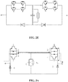
- the full-bridge module has two basic structures. The two diodes may be connected to each other with a common anode, as shown in FIG. 1 A , and the two diodes may be connected to each other with a common cathode, as shown in FIG. 1 B .
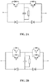
- the power electronic unit in the full-bridge module also has two implementation forms: the power electronic unit may be formed by a single fully-controlled power electronic device, or may be formed by fully-controlled power electronic devices connected in series, in parallel or a combination thereof.
- the fully-controlled power electronic device may be an IGBT, an IGCT, an IEGT, a GTO or another power electronic device. Embodiments are as shown in FIG. 2 A, FIG. 2 B , FIG. 2C, FIG. 2D and FIG. 2E .
- the full-bridge module operates as described below.
- a hybrid direct current circuit breaker includes three branches connected in parallel with each other: a primary path branch, a transfer branch and an energy absorption branch.
- the primary path branch includes a fast mechanical switch K and a small number of power electronic switches and is configured to carry the rated current of a system when the system normally operates.
- the transfer branch includes fully-controlled power electronic devices connected in series or units formed by fully-controlled power electronic devices and connected in series, and is configured to break the short-circuit current of the system.
- the energy absorption branch includes multiple groups of lightning arrester units and is configured to absorb the inductive energy of the system and remove a fault current.
- the full-bridge module provided in the present disclosure may be used for the design of the power electronic switch in the hybrid direct current circuit breaker.
- the power electronic switch in the primary path branch may be formed by a plurality of full-bridge modules connected in series and in parallel. Two modes of implementation exist: the plurality of full-bridge modules are connected first in series and then in parallel, as shown in FIG. 6A ; the plurality of full-bridge modules are connected first in parallel and then in series, as shown in FIG. 6B .
- the power electronic switch in the transfer branch is formed by fully-controlled power electronic devices connected in series or by a plurality of units including a fully-controlled power electronic device connected in series.
- the topology of the hybrid direct current circuit breaker based on a full-bridge module is used to illustrate an operation process.
- a load current merely flows through the primary path branch, that is, the load current merely flows through the fast mechanical switch K and the power electronic switch of the primary path branch.
- controllable devices, IGBTs, in a power electronic switch are kept at a trigger state, and the load current flows through the diodes in the upper leg of a full-bridge module connected anti-parallel to the left IGBTs, flows through the two right IGBTs connected in parallel in the upper leg, and flows out of the full-bridge module.
- the current does not flow through the capacitor branch in the module.
- the hybrid direct current circuit breaker receives a system breaking command, the power electronic switch of the primary path branch is latched, and the power electronic switch in the transfer branch is kept at a trigger state.
- the IGBTs in the power electronic switch of the primary path branch are turned off.
- the fault current flows through the capacitor branch in the module to charge the capacitor.
- the fast mechanical switch K is broken.
- the power electronic switch of the transfer branch is latched to achieve the transfer of the current from the transfer branch to the energy absorption branch and to complete fault current breaking.
- the direct current circuit breaker has basically the same off and on process as a cascade full-bridge direct current circuit breaker.
- the transfer branch is turned on, and if turn-on is performed on a sound line, the primary path branch is triggered; if turn-on is performed on a fault line, the transfer branch is latched.
- the embodiments of the present application may be provided as methods, systems or computer program products. Therefore, the present application may take the form of completely hardware embodiments, completely software embodiments, or a combination of software and hardware embodiments. Moreover, the present application may take the form of a computer program product implemented on one or more computer-usable storage media (including a disk memory, a compact disc read-only memory (CD-ROM), an optical memory, etc.) that include computer-usable program codes.
- a computer-usable storage media including a disk memory, a compact disc read-only memory (CD-ROM), an optical memory, etc.
- These computer program instructions may be provided for a processor of a general-purpose computer, a special-purpose computer, an embedded processor or another programmable data processing device to produce a machine, so that instructions, which are executed via the processor of the computer or another programmable data processing equipment, create a means for implementing the functions specified in one or more flows in the flowcharts and/or in one or more blocks in the block diagrams.
- These computer program instructions may also be stored in a computer-readable memory which is able to direct a computer or another programmable data processing device to operate in a particular manner, so that the instructions stored in the computer-readable memory produce an article of manufacture including instruction means which implement the functions specified in one or more flows in the flowcharts and/or in one or more blocks in the block diagrams.
Landscapes
- Driving Mechanisms And Operating Circuits Of Arc-Extinguishing High-Tension Switches (AREA)
Abstract
Description
- This application claims priority to
Chinese Patent Application No. 201910030591.X filed with the CNIPA on Jan. 14, 2019 - The present disclosure belongs to the technical field of power electronics, for example, relates to a full-bridge module, a hybrid direct current circuit breaker based on a full-bridge module, and an application method of a hybrid direct current circuit breaker.
- A high-voltage direct current circuit breaker has become one of the key equipment to ensure stable, safe and reliable operation of a system with the application of a multiterminal voltage source converter based high-voltage direct current transmission (VSC-HVDC) and direct current power grid technology. The direct current circuit breaker technology combines a mechanical switch and a fully-controlled power electronic switch, so that the direct current circuit breaker technology has both the low loss characteristic of the mechanical switch and the fast breaking characteristic of the power electronic switch. Thus, the direct current circuit breaker technology is one of the most effective technical ways to apply direct current breaking in a high-voltage transmission system. When applied to a multiterminal VSC-HVDC and direct current power grid with high-capacity overhead lines, the high-voltage direct current circuit breaker should not only have the characteristics of high speed and low loss, but also have strong current breaking and high working reliability.
- In the related art, a full-bridge-based hybrid direct current circuit breaker has the ability to cut off a fault current of 25 kA in 3 ms and has good technical performance, laying a solid foundation for engineering application. However, in the topology structure of the full-bridge-based hybrid direct current circuit breaker, each device needs to be connected in parallel with resistance-capacitance and damping circuits, which requires a large number of capacitors, thus increasing the overall volume of the circuit breaker and not conducive to a compact design. A full-bridge sub-module has also been disclosed in the related art, and requires a large number of insulated gate bipolar transistor (IGBT) devices, thus increasing the cost and the overall volume of the circuit breaker. Due to the existence of a large number of IGBTs, and each IGBT is driven separately, the required driving power is large and the secondary wiring is complicated. Meanwhile, the reliability of driving control will be reduced and the performance of the circuit breaker will be affected.
- To solve the problem existing in the related art, the present disclosure provides a full-bridge module, a hybrid direct current circuit breaker based on a full-bridge module, and an application method of a hybrid direct current circuit breaker.
- A full-bridge module is provided in an embodiment of the present disclosure and includes two power electronic units, two diodes, a resistor and a capacitor.
- The two power electronic units are connected in reverse series to form an upper leg.
- The two diodes are connected in series to form a lower leg, and anodes or cathodes of the two diodes are connected together.
- The resistor and the capacitor are connected in parallel and then connected between the upper leg and the lower leg.
- A hybrid direct current circuit breaker based on a full-bridge module is further provided in an embodiment of the present disclosure and includes a primary path branch, a transfer branch and an energy absorption branch, where the primary path branch, the transfer branch and the energy absorption branch are connected in parallel.
- The primary path branch includes a plurality of full-bridge modules.
- The transfer branch includes a plurality of fully-controlled power electronic devices or a plurality of units including a fully-controlled power electronic device.
- The primary path branch further includes a switch connected in series to the plurality of full-bridge modules.
- An application method of a hybrid direct current circuit breaker is further provided in an embodiment of the present disclosure and includes steps described below and includes steps described below.
- In condition that a system in which the hybrid direct current circuit breaker is located operates normally, a switch of the primary path branch of the hybrid direct current circuit breaker is closed and a full-bridge module of the primary path branch is kept at a trigger state.
- In condition that the system in which the hybrid direct current circuit breaker is located fails, the full-bridge module of the primary path branch is turned off, a fully-controlled power electronic device of a transfer branch is kept at a trigger state, and after a fault current is transferred to the transfer branch, the switch of the primary path branch is opened.
- After the fault current is transferred to the energy absorption branch of the hybrid direct current circuit breaker, the hybrid direct current circuit breaker clears the fault current.
-
-
FIG. 1 A is a schematic diagram showing a full-bridge module in which anodes of diodes in a lower leg are connected together according to an embodiment of the present disclosure; -
FIG. 1B is a schematic diagram showing a full-bridge module in which cathodes of diodes in a lower leg are connected together according to an embodiment of the present disclosure; -
FIG. 2A is a schematic diagram showing a full-bridge module whose power electronic unit is formed by a single fully-controlled power electronic device according to an embodiment of the present disclosure; -
FIG. 2B is a schematic diagram showing a full-bridge module whose power electronic unit is formed by fully-controlled power electronic devices connected in parallel according to an embodiment of the present disclosure; -
FIG. 2C is a schematic diagram showing a full-bridge module whose power electronic unit is formed by fully-controlled power electronic devices connected in series according to an embodiment of the present disclosure; -
FIG. 2D is a schematic diagram showing a full-bridge module whose power electronic unit is formed by fully-controlled power electronic devices first connected in parallel and then connected in series according to an embodiment of the present disclosure; -
FIG. 2E is a schematic diagram showing a full-bridge module whose power electronic unit is formed by fully-controlled power electronic devices first connected in series and then connected in parallel according to an embodiment of the present disclosure; -
FIG. 3A is a schematic diagram of a path in which a current flows from left to right when a full-bridge module is turned on according to an embodiment of the present disclosure; -
FIG. 3B is a schematic diagram showing a path in which a current flows from right to left when a full-bridge module is turned on according to an embodiment of the present disclosure; -
FIG. 4A is a schematic diagram showing a path in which a current flows from left to right when a full-bridge module is turned off according to an embodiment of the present disclosure; -
FIG. 4B is a schematic diagram showing a path in which a current flows from right to left when a full-bridge module is turned off according to an embodiment of the present disclosure; -
FIG. 5 is a schematic diagram of a topology structure of a hybrid direct current circuit breaker according to an embodiment of the present disclosure; -
FIG. 6A is a schematic diagram in which power electronic switches are first connected in series and then connected in parallel in a primary path branch of a hybrid direct current circuit breaker according to an embodiment of the present disclosure; -
FIG. 6B is a schematic diagram in which power electronic switches are first connected in parallel and then connected in series in a primary path branch of a hybrid direct current circuit breaker according to an embodiment of the present disclosure; and -
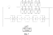
FIG. 7 is a schematic diagram of a topology structure of a hybrid direct current circuit breaker using a full-bridge module according to an embodiment of the present disclosure. - To understand the present disclosure, the content of the present disclosure is described with reference to drawings and examples of the description.
- Since a relatively large number of damping components and high-potential control units are adopted in the hybrid direct current circuit breaker, the hybrid direct current circuit breaker has the characteristics of complex structure design and complex control electrical wiring. Therefore, a full-bridge module and an application method thereof in a hybrid direct current circuit breaker are provided, which simplifies the topology structure of a cascade full-bridge direct current circuit breaker, reduces the number of high-potential control units, electrical wiring and power requirements, and conducive to a reduction of the overall volume of the circuit breaker and the improvement of working reliability.
- A full-bridge module is provided in an embodiment of the present disclosure and includes two power electronic units, two diodes, a resistor and a capacitor.
- The two power electronic units are connected in reverse series to form an upper leg.
- The two diodes are connected in series to form a lower leg, and anodes or cathodes of the two diodes are connected together.
- The resistor and the capacitor are connected in parallel and then connected between the upper leg and the lower leg.
- The power electronic unit includes one or more sub-modules, each of the one or more sub-modules is formed by a fully-controlled power electronic device in inverse-parallel connection with one diode and the diode, and a direction of a diode of each power electronic unit is opposite to a direction of one diode of the lower leg corresponding to the each power electronic unit.
- In a case of a plurality of sub-modules, the plurality of sub-modules are connected in a manner including: in series, in parallel, first in series and then in parallel, and first in parallel and then in series.
- The fully-controlled power electronic device includes: an IGBT, an integrated gate commutated thyristors (IGCT), an injection enhanced gate transistor (IEGT), or a gate turn-off thyristor (GTO).
- A hybrid direct current circuit breaker based on a full-bridge module is provided in an embodiment of the present disclosure and includes a primary path branch, a transfer branch and an energy absorption branch, where the primary path branch, the transfer branch and the energy absorption branch are connected in parallel.
- The primary path branch includes a plurality of full-bridge modules of any one of the preceding embodiments.
- The transfer branch includes a plurality of fully-controlled power electronic devices or a plurality of units including a fully-controlled power electronic device.
- The primary path branch further includes a switch connected in series to the plurality of full-bridge modules.
- The energy absorption branch includes a varistor.
- The plurality of full-bridge modules in the primary path branch are connected first in parallel and then in series or connected first in series and then in parallel.
- The plurality of fully-controlled power electronic devices or the plurality of units including the fully-controlled power electronic device in the transfer branch are connected in series.
- An application method of a hybrid direct current circuit breaker is further provided in the present disclosure and includes steps described below.
- In condition that a system in which the hybrid direct current circuit breaker is located operates normally, a switch of the primary path branch of the hybrid direct current circuit breaker is closed and a full-bridge module of the primary path branch is kept at a trigger state.
- In condition that the system in which the hybrid direct current circuit breaker is located fails, the full-bridge module of the primary path branch is turned off, a fully-controlled power electronic device of a transfer branch is kept at a trigger state, and after a fault current is transferred to the transfer branch, the switch of the primary path branch is opened.
- After the fault current is transferred to the energy absorption branch of the hybrid direct current circuit breaker, the hybrid direct current circuit breaker clears the fault current.
- In an embodiment, the step in which in condition that a system in which the hybrid direct current circuit breaker is located operates normally, a switch of the primary path branch of the hybrid direct current circuit breaker is closed and a full-bridge module of the primary path branch is kept at a trigger state includes a step described below.
- The current passes from an input end through a diode in inverse-parallel connection with a fully-controlled power electronic device in one power electronic unit of the upper leg of the full-bridge module, and then passes through a fully-controlled power electronic device in the other power electronic unit of the upper leg to flow out of the full-bridge module.
- In an embodiment, the step in which in condition that the system in which the hybrid direct current circuit breaker is located fails, the full-bridge module of the primary path branch is turned off, a fully-controlled power electronic device of a transfer branch is kept at a trigger state, and after a fault current is transferred to the transfer branch, the switch of the primary path branch is opened includes steps described below.
- Based on a received breaking command, the fully-controlled power electronic device of the full-bridge module of the primary path branch is turned off, and a capacitor of the full-bridge module of the primary path branch is charged through the fault current.
- In condition that a voltage across two ends of the hybrid direct current circuit breaker reaches a turn-on voltage of the transfer branch, the fault current is transferred to the transfer branch.
- After the fault current transfer is completed, the switch of the primary path branch is opened.
- 1. The full-bridge module provided in the present disclosure includes two power electronic units, two diodes, a resistor and a capacitor. The two power electronic units are connected in reverse series to form an upper leg. The two diodes are connected in series to form a lower leg, and anodes or cathodes of the two diodes are connected together. The resistor and the capacitor are connected in parallel and then connected between the upper leg and the lower leg. Thus, common damping of devices connected in reverse series is achieved, the number of passive elements is reduced, and the topology design is simplified, conducive to a reduction of the volume and cost of equipment.
- 2. The full-bridge module, the hybrid direct current circuit breaker based on a full-bridge module, and an application method are provided in the present disclosure, achieving the potential unification of fully-controlled power electronic devices, conducive to a reduction of the number of high-potential control units, simplifying the control electrical wiring, and conducive to the improvement of the overall reliability of equipment.
- 3. The full-bridge module, the hybrid direct current circuit breaker based on a full-bridge module, and an application method are provided in the present disclosure, achieving the compact press-fitting structure design of fully-controlled power electronic devices of the hybrid direct current circuit breaker, easy to reduce stray parameters and to achieve overvoltage suppression, and improving the overall application reliability and economy.
- In an embodiment, a full-bridge module includes power electronic units, diodes, a resistor and a capacitor. A full-bridge structure is formed by two power electronic units and two diodes. The capacitor and a resistor R are connected in parallel and then connected between the upper leg and the lower leg of the full-bridge module. As shown in
FIG. 1 , the full-bridge module has two basic structures. The two diodes may be connected to each other with a common anode, as shown inFIG. 1 A , and the two diodes may be connected to each other with a common cathode, as shown inFIG. 1 B . The power electronic unit in the full-bridge module also has two implementation forms: the power electronic unit may be formed by a single fully-controlled power electronic device, or may be formed by fully-controlled power electronic devices connected in series, in parallel or a combination thereof. The fully-controlled power electronic device may be an IGBT, an IGCT, an IEGT, a GTO or another power electronic device. Embodiments are as shown inFIG. 2 A, FIG. 2 B ,FIG. 2C, FIG. 2D andFIG. 2E . - In an embodiment, the full-bridge module operates as described below.
- When the full-bridge module is turned on, if a current flows from left to right, the current flows through the diodes connected anti-parallel to IGBT1 and to IGBT2 respectively and flows through IGBT3 and IGBT4, as shown in
FIG. 3A ; and if a current flows from right to left, the current flows through the diodes connected anti-parallel to IGBT3 and IGBT4 respectively and flows through IGBT1 and IGBT2, as shown inFIG. 3B . - When the full-bridge module is turned off, if a current flows from left to right, the current flows through the diodes connected anti-parallel to IGBT1 and to IGBT2 respectively and flows through the capacitor of the module and a
diode 5, as shown inFIG. 4A ; and if a current flows from right to left, the current flows through the diodes connected anti-parallel to IGBT3 and IGBT4 respectively and flows through the capacitor of the module and adiode 6, as shown inFIG. 4B . - As shown in
FIG. 5 , a hybrid direct current circuit breaker includes three branches connected in parallel with each other: a primary path branch, a transfer branch and an energy absorption branch. The primary path branch includes a fast mechanical switch K and a small number of power electronic switches and is configured to carry the rated current of a system when the system normally operates. The transfer branch includes fully-controlled power electronic devices connected in series or units formed by fully-controlled power electronic devices and connected in series, and is configured to break the short-circuit current of the system. The energy absorption branch includes multiple groups of lightning arrester units and is configured to absorb the inductive energy of the system and remove a fault current. - The full-bridge module provided in the present disclosure may be used for the design of the power electronic switch in the hybrid direct current circuit breaker. The power electronic switch in the primary path branch may be formed by a plurality of full-bridge modules connected in series and in parallel. Two modes of implementation exist: the plurality of full-bridge modules are connected first in series and then in parallel, as shown in
FIG. 6A ; the plurality of full-bridge modules are connected first in parallel and then in series, as shown inFIG. 6B . The power electronic switch in the transfer branch is formed by fully-controlled power electronic devices connected in series or by a plurality of units including a fully-controlled power electronic device connected in series. - As shown in
FIG. 7 , the topology of the hybrid direct current circuit breaker based on a full-bridge module is used to illustrate an operation process. - When the system normally operates, a load current merely flows through the primary path branch, that is, the load current merely flows through the fast mechanical switch K and the power electronic switch of the primary path branch. At this time, controllable devices, IGBTs, in a power electronic switch are kept at a trigger state, and the load current flows through the diodes in the upper leg of a full-bridge module connected anti-parallel to the left IGBTs, flows through the two right IGBTs connected in parallel in the upper leg, and flows out of the full-bridge module. At this time, the current does not flow through the capacitor branch in the module. After a fault occurs, the hybrid direct current circuit breaker receives a system breaking command, the power electronic switch of the primary path branch is latched, and the power electronic switch in the transfer branch is kept at a trigger state. The IGBTs in the power electronic switch of the primary path branch are turned off. At this time, the fault current flows through the capacitor branch in the module to charge the capacitor. When the voltage across two ends of the circuit breaker reaches the turn-on voltage of the transfer branch, the fault current is transferred from the primary path branch to the transfer branch. After the transfer is completed, the fast mechanical switch K is broken. After the fast mechanical switch K is broken, the power electronic switch of the transfer branch is latched to achieve the transfer of the current from the transfer branch to the energy absorption branch and to complete fault current breaking. The direct current circuit breaker has basically the same off and on process as a cascade full-bridge direct current circuit breaker. The transfer branch is turned on, and if turn-on is performed on a sound line, the primary path branch is triggered; if turn-on is performed on a fault line, the transfer branch is latched.
- The embodiments of the present application may be provided as methods, systems or computer program products. Therefore, the present application may take the form of completely hardware embodiments, completely software embodiments, or a combination of software and hardware embodiments. Moreover, the present application may take the form of a computer program product implemented on one or more computer-usable storage media (including a disk memory, a compact disc read-only memory (CD-ROM), an optical memory, etc.) that include computer-usable program codes.
- The present application is described with reference to flowcharts and/or block diagrams of methods, devices (systems) and computer program products according to the embodiments of the present application. In the present application, computer program instructions may be used to implement each flow and/or block in the flowcharts and/or block diagrams and a combination of flows and/or blocks in the flowcharts and/or block diagrams. These computer program instructions may be provided for a processor of a general-purpose computer, a special-purpose computer, an embedded processor or another programmable data processing device to produce a machine, so that instructions, which are executed via the processor of the computer or another programmable data processing equipment, create a means for implementing the functions specified in one or more flows in the flowcharts and/or in one or more blocks in the block diagrams.
- These computer program instructions may also be stored in a computer-readable memory which is able to direct a computer or another programmable data processing device to operate in a particular manner, so that the instructions stored in the computer-readable memory produce an article of manufacture including instruction means which implement the functions specified in one or more flows in the flowcharts and/or in one or more blocks in the block diagrams.
- These computer program instructions may also be loaded onto a computer or another programmable data processing device so that a series of operation steps are performed on the computer or another programmable device to produce processing implemented by a computer. Therefore, instructions executed on a computer or another programmable device provide steps for implementing the functions specified in one or more flows in the flowcharts and/or in one or more blocks in the block diagrams.
Claims (11)
- A full-bridge module, comprising: two power electronic units, two diodes, a resistor and a capacitor;wherein the two power electronic units are connected in reverse series to form an upper leg,the two diodes are connected in series to form a lower leg, anodes or cathodes of the two diodes are connected together, andthe resistor and the capacitor are connected in parallel and then connected between the upper leg and the lower leg.
- The full-bridge module of claim 1, wherein each of the two power electronic units comprises one or more sub-modules, each of the one or more sub-modules is formed by a fully-controlled power electronic device in inverse-parallel connection with one diode and the diode, and a direction of a diode of each of the two power electronic units is opposite to a direction of one diode of the lower leg corresponding to the each of the two power electronic units.
- The full-bridge module of claim 2, wherein the one or more sub-modules comprises a plurality of sub-modules, the plurality of sub-modules are connected in a manner comprising: in series, in parallel, first in series and then in parallel, and first in parallel and then in series.
- The full-bridge module of claim 2, wherein the fully-controlled power electronic device comprises: an insulated gate bipolar transistor, IGBT, an integrated gate commutated thyristor, IGCT, an injection enhanced gate transistor, IEGT, or a gate turn-off thyristor, GTO.
- A hybrid direct current circuit breaker based on a full-bridge module, comprising: a primary path branch, a transfer branch and an energy absorption branch, wherein the primary path branch, the transfer branch and the energy absorption branch are connected in parallel;wherein the primary path branch comprises a plurality of full-bridge modules of any one of claims 1 to 4;the transfer branch comprises a plurality of fully-controlled power electronic devices or a plurality of units comprising a fully-controlled power electronic device; andthe primary path branch further comprises a switch connected in series to the plurality of full-bridge modules.
- The hybrid direct current circuit breaker of claim 5, wherein the energy absorption branch comprises a varistor.
- The hybrid direct current circuit breaker of claim 5, wherein the plurality of full-bridge modules in the primary path branch are connected first in parallel and then in series or connected first in series and then in parallel.
- The hybrid direct current circuit breaker of claim 5, wherein the plurality of fully-controlled power electronic devices or the plurality of units comprising the fully-controlled power electronic device in the transfer branch are connected in series.
- An application method of the hybrid direct current circuit breaker of any one of claims 5 to 8, comprising:in response to a system in which the hybrid direct current circuit breaker is located operating normally, closing the switch of the primary path branch of the hybrid direct current circuit breaker and keeping the plurality of full-bridge modules of the primary path branch at a trigger state;in response to the system in which the hybrid direct current circuit breaker is located being failed, turning off the plurality of full-bridge modules of the primary path branch, keeping a fully-controlled power electronic device of the transfer branch at a trigger state, and after a fault current is transferred to the transfer branch, opening the switch of the primary path branch; and after the fault current is transferred to the energy absorption branch of the hybrid direct current circuit breaker, clearing, by the hybrid direct current circuit breaker, the fault current.
- The method of claim 9, wherein in response to the system in which the hybrid direct current circuit breaker is located operating normally, the closing the switch of the primary path branch of the hybrid direct current circuit breaker and keeping the plurality of full-bridge modules of the primary path branch at the trigger state comprises:
a current passing from an input end through a diode connected anti-parallel to a fully-controlled power electronic device in one of the two power electronic units of the upper leg of the full-bridge module, and then passing through a fully-controlled power electronic device in the other of the two power electronic units of the upper leg to flow out of the full-bridge module. - The method of claim 9, wherein in response to the system in which the hybrid direct current circuit breaker is located being failed, turning off the plurality of full-bridge modules of the primary path branch, keeping the fully-controlled power electronic device of the transfer branch at the trigger state, and after the fault current is transferred to the transfer branch, opening the switch of the primary path branch comprises:based on a received breaking command, turning off a fully-controlled power electronic device of the plurality of full-bridge modules of the primary path branch, and charging capacitors of the plurality of full-bridge modules of the primary path branch through the fault current;in response to a voltage across two ends of the hybrid direct current circuit breaker reaching a turn-on voltage of the transfer branch, transferring the fault current to the transfer branch; and opening the switch of the primary path branch after the fault current transfer is completed.
Applications Claiming Priority (2)
| Application Number | Priority Date | Filing Date | Title |
|---|---|---|---|
| CN201910030591.XA CN109981092A (en) | 2019-01-14 | 2019-01-14 | The hybrid dc circuit breaker and application method of a kind of full-bridge modules, full-bridge modules |
| PCT/CN2019/117572 WO2020147400A1 (en) | 2019-01-14 | 2019-11-12 | Full-bridge module, hybrid direct current circuit breaker of full-bridge module, and application method |
Publications (3)
| Publication Number | Publication Date |
|---|---|
| EP3913805A1 true EP3913805A1 (en) | 2021-11-24 |
| EP3913805A4 EP3913805A4 (en) | 2022-09-14 |
| EP3913805B1 EP3913805B1 (en) | 2025-10-01 |
Family
ID=67076572
Family Applications (1)
| Application Number | Title | Priority Date | Filing Date |
|---|---|---|---|
| EP19910433.2A Active EP3913805B1 (en) | 2019-01-14 | 2019-11-12 | Full-bridge module, hybrid direct current circuit breaker of full-bridge module, and application method |
Country Status (3)
| Country | Link |
|---|---|
| EP (1) | EP3913805B1 (en) |
| CN (1) | CN109981092A (en) |
| WO (1) | WO2020147400A1 (en) |
Families Citing this family (5)
| Publication number | Priority date | Publication date | Assignee | Title |
|---|---|---|---|---|
| CN109981092A (en) * | 2019-01-14 | 2019-07-05 | 全球能源互联网研究院有限公司 | The hybrid dc circuit breaker and application method of a kind of full-bridge modules, full-bridge modules |
| CN111509677A (en) * | 2020-04-03 | 2020-08-07 | 全球能源互联网研究院有限公司 | Full-bridge module and direct current circuit breaker |
| CN112865061A (en) * | 2021-01-07 | 2021-05-28 | 天津大学 | Direct current load switch based on power electronic device and switching method thereof |
| CN114498546B (en) * | 2021-12-28 | 2023-01-20 | 清华大学 | Hybrid dual-bridge type direct current breaker topological circuit and control method thereof |
| DE102024205317A1 (en) | 2024-06-10 | 2025-12-11 | Robert Bosch Gesellschaft mit beschränkter Haftung | Control device for controlling an electric three-phase machine and method for operating an electric three-phase machine |
Family Cites Families (18)
| Publication number | Priority date | Publication date | Assignee | Title |
|---|---|---|---|---|
| US9654102B2 (en) * | 2014-10-09 | 2017-05-16 | General Electric Company | Hybrid direct-current circuit breaker |
| CN104635151B (en) * | 2014-12-29 | 2018-07-20 | 国家电网公司 | A kind of cascade full-bridge direct current breaker low pressure equivalent test circuit and its detection method |
| CN105807216A (en) * | 2014-12-29 | 2016-07-27 | 国家电网公司 | Testing device of high voltage direct current circuit breaker full bridge module and testing method thereof |
| CN106558865B (en) * | 2015-09-25 | 2019-03-15 | 全球能源互联网研究院 | An improved cascaded full-bridge high-voltage DC circuit breaker and its rapid reclosing method |
| CN105790234A (en) * | 2016-03-15 | 2016-07-20 | 许继电气股份有限公司 | High-voltage direct-current circuit breaker |
| CN105655966A (en) * | 2016-03-15 | 2016-06-08 | 许继电气股份有限公司 | Direct current breaker |
| CN205693347U (en) * | 2016-06-16 | 2016-11-16 | 南方电网科学研究院有限责任公司 | A Hybrid DC Circuit Breaker |
| CN105896492B (en) * | 2016-06-16 | 2019-02-15 | 南方电网科学研究院有限责任公司 | A hybrid DC circuit breaker |
| CN107645154B (en) * | 2016-07-20 | 2020-03-06 | 全球能源互联网研究院有限公司 | Novel combined direct current circuit breaker and application method thereof |
| CN107769179A (en) * | 2016-08-23 | 2018-03-06 | 全球能源互联网研究院 | It is a kind of based on can shut-off valve force electric current transfevent blended learning |
| CN106229952B (en) * | 2016-08-31 | 2018-12-07 | 许继电气股份有限公司 | Fuse assembling device and control method, dc circuit breaker and control method |
| CN108123423B (en) * | 2016-11-28 | 2019-10-18 | 华北电力大学 | A hybrid high voltage DC circuit breaker based on thyristor full bridge module main circuit breaker switch type |
| CN106971883A (en) * | 2017-04-19 | 2017-07-21 | 中国科学院电工研究所 | A kind of dc circuit breaker of hybrid switch device |
| CN107482576B (en) * | 2017-09-15 | 2019-04-16 | 浙江大学 | A Startup Control Strategy of a Hybrid HVDC Circuit Breaker |
| CN107749616B (en) * | 2017-09-29 | 2019-01-04 | 浙江大学 | A kind of capacitive dc circuit breaker of decreasing loss formula and its DC Line Fault processing strategie |
| CN107748324A (en) * | 2017-10-16 | 2018-03-02 | 国网浙江省电力公司电力科学研究院 | The protection breaking current test method and system of a kind of hybrid dc circuit breaker |
| CN107785867A (en) * | 2017-12-08 | 2018-03-09 | 浙江大学 | A kind of dc circuit breaker for reducing drop-out current and its DC Line Fault processing strategy |
| CN109981092A (en) * | 2019-01-14 | 2019-07-05 | 全球能源互联网研究院有限公司 | The hybrid dc circuit breaker and application method of a kind of full-bridge modules, full-bridge modules |
-
2019
- 2019-01-14 CN CN201910030591.XA patent/CN109981092A/en active Pending
- 2019-11-12 WO PCT/CN2019/117572 patent/WO2020147400A1/en not_active Ceased
- 2019-11-12 EP EP19910433.2A patent/EP3913805B1/en active Active
Also Published As
| Publication number | Publication date |
|---|---|
| CN109981092A (en) | 2019-07-05 |
| EP3913805A4 (en) | 2022-09-14 |
| WO2020147400A1 (en) | 2020-07-23 |
| EP3913805B1 (en) | 2025-10-01 |
Similar Documents
| Publication | Publication Date | Title |
|---|---|---|
| EP3913805B1 (en) | Full-bridge module, hybrid direct current circuit breaker of full-bridge module, and application method | |
| US10811864B2 (en) | DC circuit breaker with counter current generation | |
| KR101924707B1 (en) | Voltage-source multi-level converter, direct-current power transmission system and fault processing method and device | |
| EP3131166B1 (en) | Passive high-voltage direct-current circuit breaker and implementation method therefor | |
| CN105870877B (en) | A thyristor-based passive hybrid DC circuit breaker and its application method | |
| EP3355431B1 (en) | Cascaded full-bridge high-voltage dc circuit breaker | |
| KR101720112B1 (en) | apparatus for limiting current of circuit or breaking current, and control method thereof | |
| CN109217239B (en) | Direct current breaker with breaking selection function | |
| CN112653087B (en) | Direct-current circuit breaker adopting composite solid-state switch and control method thereof | |
| CN104410101A (en) | MMC (Modular Multilevel Converter) topological structure with power grid black-start and direct current failure ride-through capabilities | |
| CN106786403A (en) | A kind of DC solid circuit breaker with continuous current circuit | |
| Li et al. | A DC fault handling method of the MMC-based DC system | |
| CN107453336A (en) | One kind cascade full-bridge direct current breaker | |
| CN107370393A (en) | A kind of Modularized multi-level converter sub-module topological structure and its guard method | |
| KR101689824B1 (en) | Modular Multilevel Converter and Submodule of the Converter | |
| CN111509677A (en) | Full-bridge module and direct current circuit breaker | |
| CN107104418A (en) | Converter valve submodule unit, modularization multi-level converter and its control method | |
| CN107863760A (en) | A current-limiting DC circuit breaker based on a capacitor commutation unit and its control method | |
| CN114204517A (en) | Hybrid direct current breaker and control method thereof | |
| Sander et al. | A novel current-injection based design for HVDC circuit breakers | |
| CN107749615A (en) | It is a kind of tactful based on the dc circuit breaker for sealing in capacitor and its DC Line Fault processing | |
| Shan et al. | A cost-effective design of soft turn-off diode-bridge power electronic switch for high-performance hybrid DC circuit breakers | |
| Zhang et al. | An improved sub-module topology for protecting MMC power devices under DC-side short circuit fault | |
| WO2018032658A1 (en) | Novel hybrid direct current circuit breaker and power unit | |
| CN107749616A (en) | One kind drop damage formula capacitor type dc circuit breaker and its DC Line Fault processing strategy |
Legal Events
| Date | Code | Title | Description |
|---|---|---|---|
| STAA | Information on the status of an ep patent application or granted ep patent |
Free format text: STATUS: THE INTERNATIONAL PUBLICATION HAS BEEN MADE |
|
| PUAI | Public reference made under article 153(3) epc to a published international application that has entered the european phase |
Free format text: ORIGINAL CODE: 0009012 |
|
| STAA | Information on the status of an ep patent application or granted ep patent |
Free format text: STATUS: REQUEST FOR EXAMINATION WAS MADE |
|
| 17P | Request for examination filed |
Effective date: 20210118 |
|
| AK | Designated contracting states |
Kind code of ref document: A1 Designated state(s): AL AT BE BG CH CY CZ DE DK EE ES FI FR GB GR HR HU IE IS IT LI LT LU LV MC MK MT NL NO PL PT RO RS SE SI SK SM TR |
|
| DAV | Request for validation of the european patent (deleted) | ||
| DAX | Request for extension of the european patent (deleted) | ||
| A4 | Supplementary search report drawn up and despatched |
Effective date: 20220812 |
|
| RIC1 | Information provided on ipc code assigned before grant |
Ipc: H01H 71/00 20060101ALI20220808BHEP Ipc: H03K 17/51 20060101AFI20220808BHEP |
|
| STAA | Information on the status of an ep patent application or granted ep patent |
Free format text: STATUS: EXAMINATION IS IN PROGRESS |
|
| 17Q | First examination report despatched |
Effective date: 20231114 |
|
| GRAP | Despatch of communication of intention to grant a patent |
Free format text: ORIGINAL CODE: EPIDOSNIGR1 |
|
| STAA | Information on the status of an ep patent application or granted ep patent |
Free format text: STATUS: GRANT OF PATENT IS INTENDED |
|
| INTG | Intention to grant announced |
Effective date: 20250424 |
|
| GRAS | Grant fee paid |
Free format text: ORIGINAL CODE: EPIDOSNIGR3 |
|
| GRAA | (expected) grant |
Free format text: ORIGINAL CODE: 0009210 |
|
| STAA | Information on the status of an ep patent application or granted ep patent |
Free format text: STATUS: THE PATENT HAS BEEN GRANTED |
|
| AK | Designated contracting states |
Kind code of ref document: B1 Designated state(s): AL AT BE BG CH CY CZ DE DK EE ES FI FR GB GR HR HU IE IS IT LI LT LU LV MC MK MT NL NO PL PT RO RS SE SI SK SM TR |
|
| REG | Reference to a national code |
Ref country code: GB Ref legal event code: FG4D Ref country code: CH Ref legal event code: F10 Free format text: ST27 STATUS EVENT CODE: U-0-0-F10-F00 (AS PROVIDED BY THE NATIONAL OFFICE) Effective date: 20251001 |
|
| REG | Reference to a national code |
Ref country code: DE Ref legal event code: R096 Ref document number: 602019076512 Country of ref document: DE |
|
| REG | Reference to a national code |
Ref country code: IE Ref legal event code: FG4D |
|
| PGFP | Annual fee paid to national office [announced via postgrant information from national office to epo] |
Ref country code: DE Payment date: 20251124 Year of fee payment: 7 |
|
| REG | Reference to a national code |
Ref country code: NL Ref legal event code: MP Effective date: 20251001 |
|
| REG | Reference to a national code |
Ref country code: AT Ref legal event code: MK05 Ref document number: 1843618 Country of ref document: AT Kind code of ref document: T Effective date: 20251001 |
|
| PG25 | Lapsed in a contracting state [announced via postgrant information from national office to epo] |
Ref country code: NL Free format text: LAPSE BECAUSE OF FAILURE TO SUBMIT A TRANSLATION OF THE DESCRIPTION OR TO PAY THE FEE WITHIN THE PRESCRIBED TIME-LIMIT Effective date: 20251001 |
|
| PG25 | Lapsed in a contracting state [announced via postgrant information from national office to epo] |
Ref country code: ES Free format text: LAPSE BECAUSE OF FAILURE TO SUBMIT A TRANSLATION OF THE DESCRIPTION OR TO PAY THE FEE WITHIN THE PRESCRIBED TIME-LIMIT Effective date: 20251001 |
|
| REG | Reference to a national code |
Ref country code: LT Ref legal event code: MG9D |
|
| PG25 | Lapsed in a contracting state [announced via postgrant information from national office to epo] |
Ref country code: NO Free format text: LAPSE BECAUSE OF FAILURE TO SUBMIT A TRANSLATION OF THE DESCRIPTION OR TO PAY THE FEE WITHIN THE PRESCRIBED TIME-LIMIT Effective date: 20260101 |
|
| PG25 | Lapsed in a contracting state [announced via postgrant information from national office to epo] |
Ref country code: AT Free format text: LAPSE BECAUSE OF FAILURE TO SUBMIT A TRANSLATION OF THE DESCRIPTION OR TO PAY THE FEE WITHIN THE PRESCRIBED TIME-LIMIT Effective date: 20251001 Ref country code: FI Free format text: LAPSE BECAUSE OF FAILURE TO SUBMIT A TRANSLATION OF THE DESCRIPTION OR TO PAY THE FEE WITHIN THE PRESCRIBED TIME-LIMIT Effective date: 20251001 Ref country code: HR Free format text: LAPSE BECAUSE OF FAILURE TO SUBMIT A TRANSLATION OF THE DESCRIPTION OR TO PAY THE FEE WITHIN THE PRESCRIBED TIME-LIMIT Effective date: 20251001 |
|
| PG25 | Lapsed in a contracting state [announced via postgrant information from national office to epo] |
Ref country code: RS Free format text: LAPSE BECAUSE OF FAILURE TO SUBMIT A TRANSLATION OF THE DESCRIPTION OR TO PAY THE FEE WITHIN THE PRESCRIBED TIME-LIMIT Effective date: 20260101 |
|
| PG25 | Lapsed in a contracting state [announced via postgrant information from national office to epo] |
Ref country code: IS Free format text: LAPSE BECAUSE OF FAILURE TO SUBMIT A TRANSLATION OF THE DESCRIPTION OR TO PAY THE FEE WITHIN THE PRESCRIBED TIME-LIMIT Effective date: 20260201 |
|
| PG25 | Lapsed in a contracting state [announced via postgrant information from national office to epo] |
Ref country code: CZ Free format text: LAPSE BECAUSE OF FAILURE TO SUBMIT A TRANSLATION OF THE DESCRIPTION OR TO PAY THE FEE WITHIN THE PRESCRIBED TIME-LIMIT Effective date: 20251001 Ref country code: PT Free format text: LAPSE BECAUSE OF FAILURE TO SUBMIT A TRANSLATION OF THE DESCRIPTION OR TO PAY THE FEE WITHIN THE PRESCRIBED TIME-LIMIT Effective date: 20260202 |
|
| PG25 | Lapsed in a contracting state [announced via postgrant information from national office to epo] |
Ref country code: PL Free format text: LAPSE BECAUSE OF FAILURE TO SUBMIT A TRANSLATION OF THE DESCRIPTION OR TO PAY THE FEE WITHIN THE PRESCRIBED TIME-LIMIT Effective date: 20251001 |
|
| PG25 | Lapsed in a contracting state [announced via postgrant information from national office to epo] |
Ref country code: LV Free format text: LAPSE BECAUSE OF FAILURE TO SUBMIT A TRANSLATION OF THE DESCRIPTION OR TO PAY THE FEE WITHIN THE PRESCRIBED TIME-LIMIT Effective date: 20251001 |
|
| PG25 | Lapsed in a contracting state [announced via postgrant information from national office to epo] |
Ref country code: BG Free format text: LAPSE BECAUSE OF FAILURE TO SUBMIT A TRANSLATION OF THE DESCRIPTION OR TO PAY THE FEE WITHIN THE PRESCRIBED TIME-LIMIT Effective date: 20251001 |