EP3913737B1 - Pedestal including tilted azimuth axis - Google Patents
Pedestal including tilted azimuth axis Download PDFInfo
- Publication number
- EP3913737B1 EP3913737B1 EP20742073.8A EP20742073A EP3913737B1 EP 3913737 B1 EP3913737 B1 EP 3913737B1 EP 20742073 A EP20742073 A EP 20742073A EP 3913737 B1 EP3913737 B1 EP 3913737B1
- Authority
- EP
- European Patent Office
- Prior art keywords
- tracker
- pedestal
- supporter
- respect
- cable
- Prior art date
- Legal status (The legal status is an assumption and is not a legal conclusion. Google has not performed a legal analysis and makes no representation as to the accuracy of the status listed.)
- Active
Links
Images







Classifications
-
- H—ELECTRICITY
- H01—ELECTRIC ELEMENTS
- H01Q—ANTENNAS, i.e. RADIO AERIALS
- H01Q1/00—Details of, or arrangements associated with, antennas
- H01Q1/12—Supports; Mounting means
- H01Q1/1207—Supports; Mounting means for fastening a rigid aerial element
-
- H—ELECTRICITY
- H01—ELECTRIC ELEMENTS
- H01Q—ANTENNAS, i.e. RADIO AERIALS
- H01Q1/00—Details of, or arrangements associated with, antennas
- H01Q1/12—Supports; Mounting means
- H01Q1/125—Means for positioning
-
- H—ELECTRICITY
- H01—ELECTRIC ELEMENTS
- H01Q—ANTENNAS, i.e. RADIO AERIALS
- H01Q1/00—Details of, or arrangements associated with, antennas
- H01Q1/12—Supports; Mounting means
- H01Q1/18—Means for stabilising antennas on an unstable platform
-
- H—ELECTRICITY
- H01—ELECTRIC ELEMENTS
- H01Q—ANTENNAS, i.e. RADIO AERIALS
- H01Q3/00—Arrangements for changing or varying the orientation or the shape of the directional pattern of the waves radiated from an antenna or antenna system
- H01Q3/02—Arrangements for changing or varying the orientation or the shape of the directional pattern of the waves radiated from an antenna or antenna system using mechanical movement of antenna or antenna system as a whole
- H01Q3/08—Arrangements for changing or varying the orientation or the shape of the directional pattern of the waves radiated from an antenna or antenna system using mechanical movement of antenna or antenna system as a whole for varying two co-ordinates of the orientation
Definitions
- the following example embodiments relate to a pedestal with a tilted azimuth axis.
- a typical device is configured to have an azimuth axis (AZ axis) that substantially coincides with a zenith line joining the device provided on a reference plane with a zenith.
- AZ axis azimuth axis
- an antenna of this device tracks an object (e.g., satellite) that transmits and receives radio waves on a field of view FOV
- the antenna needs to rotate relatively rapidly when an orientation axis thereof is in a region close to the zenith, rather than when in the other regions within the field of view. Accordingly, a relatively large capacity of power source is required to control the rotation velocity of the antenna while the orientation axis of the antenna is in a region close to the zenith.
- a pedestal for tracking an antenna is disclosed in US Patent Application Publication No. 2014/0299734 .
- the pedestal disclosed in the publication is configured to be capable of three-axis driving for stabilizing the pointing of a mobile antenna.
- Such a three-axis driving pedestal requires a complex structure to implement high degrees of freedom.
- JPS63283205 and US6198542B1 disclose supporters with inclined rotation axes.
- An aspect provides a pedestal configured to use a relatively small capacity of power source through a simple structure while stably tracking a target that transmits and receives radio waves and to use a small capacity of power source at the same time removing a section showing a sharp rise of a drive velocity in a region within a field of view through a structure for avoiding the keyhole effect.
- a pedestal including a supporter having an azimuth axis and a pivot on the azimuth axis, and a tracker connected to the pivot and configured to track an object within a field of view, wherein the azimuth axis is tilted with respect to a reference plane on which the supporter is installed in a direction away from a zenith line joining the pivot with a zenith within the field of view, and a tilt angle between the azimuth axis and the reference plane is set to correspond to an orbital angle of the object, wherein the supporter includes a first supporter installed on the reference plane and having an inclined surface that is inclined with respect to the reference plane, and a second supporter installed on the inclined surface and having the azimuth axis and the pivot.
- the tracker has an orientation axis, where the tilt angle may be set such that a singularity point at which the orientation axis of the tracker coincides with the azimuth axis is present in a vicinity of the field of view or outside the field of view.
- the supporter may have a fixed rotation with respect to the reference plane.
- the tracker may be configured to rotate independently with respect to each of the azimuth axis and the pivot.
- the pedestal may further include a cable connecting the first supporter and the tracker, where space may be provided between the first supporter and the tracker to sufficiently receive the cable so as to prevent interference between the cable and the tracker and a twist of the cable while the tracker rotates with respect to the pivot.
- the cable may be placed on a same side of the tracker and the first supporter.
- the cable may be prevented from wrapping while the tracker rotates with respect to the pivot.
- the cable may have a slack configuration while the tracker rotates with respect to the pivot in a first direction, and have a taut configuration while the tracker rotates with respect to the pivot in a second direction which is opposite to the first direction.
- a pedestal may have an azimuth axis that is tilted to the outside of a determined field of view and thus, prevent the keyhole effect while being driven within the field of view.
- a pedestal may be configured to require no rapid adjustment of a rotation velocity of an antenna while an orientation axis thereof passes through a region close to a zenith.
- a pedestal may require relatively low power to rotate an antenna and thus, reduce a capacity of a power source that is used.
- first, second, A, B, (a), and (b) may be used to describe constituent elements of the example embodiments. These terms are used only for the purpose of discriminating one constituent element from another constituent element, and the nature, the sequences, or the orders of the constituent elements are not limited by the terms.
- one constituent element is described as being “connected”, “coupled”, or “attached” to another constituent element, it should be understood that one constituent element can be connected or attached directly to another constituent element, and an intervening constituent element can also be “connected”, “coupled”, or “attached” to the constituent elements.
- the constituent element which has the same common function as the constituent element included in any one example embodiment, will be described by using the same name in other example embodiments. Unless disclosed to the contrary, the configuration disclosed in any one example embodiment may be applied to other example embodiments, and the specific description of the repeated configuration will be omitted.
- FIG. 1 schematically illustrates an example of the use of a pedestal according to an example embodiment.
- a pedestal 10 operates to have an orientation axis OT track an object O on a system 1 where the pedestal 10 is used.
- the object O may include, for example, an artificial satellite that transmits and receives radio waves.
- the pedestal 10 has an elevational axis EL, which is a main axis, and a tilted azimuth axis TAZ, where the orientation axis OT of the pedestal 10 is configured to rotate independently with respect to the elevational axis EL and the tilted azimuth axis TAZ.
- a field of view FOV refers to a working range in which the orientation axis OT of the pedestal 10 may track the object O.
- the field of view FOV is determined based on a range of rotation of the orientation axis OT with respect to the elevational axis EL and the tilted azimuth axis TAZ.
- the field of view FOV may generally have a conical shape about the position of the pedestal 10.
- a zenith ZP refers to a point at which an extension line perpendicular to a reference plane GD on which the pedestal 10 is installed meets the field of view.
- the extension line perpendicular to the reference plane GD is defined as a zenith line ZL.
- the object O moves along a set orbit on the field of view FOV.
- an orbital plane including the orbit of the object O and a reference point on the reference plane GD on which the pedestal 10 is positioned is defined.
- An orbital angle is defined as an angle ⁇ formed by the orbital plane and a vertical plane VP that passes through the zenith ZP and is perpendicular to the reference plane GD.
- a tilt angle of the tilted azimuth axis TAZ with respect to the reference plane GD is set to correspond to the orbital angle so as to stably track the object O within the field of view FOV.
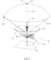
- FIG. 2 is a conceptual diagram to describe a singularity point of a pedestal according to an example embodiment.
- the pedestal 10 may include a tracker 130 having an orientation axis OT that tracks an object.
- the tracker 130 may rotate with respect to the elevational axis EL about the pivot, and rotate with respect to the tilted azimuth axis TAZ independently from the rotation with respect to the elevational axis.
- the singularity point SP is defined as a point on a celestial body on which the orientation axis OT of the tracker 130 coincides with the tilted azimuth axis TAZ. While an object O passes through a region in the vicinity of the singularity point SP, a radical change in the rotation direction and/or the rotation velocity of the tracker 130 that tracks the object O, the so-called keyhole effect, may occur. In this case, a power source needs to have a large capacity to drive the tracker 130 having the rotation direction and/or the rotation velocity that changes rapidly, and a large structural rigidness of the pedestal 10 may be required accordingly to support the large-capacity power source. Thus, the singularity point SP may not be present at the center of the field of view where an object O is mainly tracked, but in the vicinity of the field of view or preferably outside the field of view.
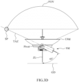
- FIGS. 3A to 3E are conceptual diagrams to describe a relationship between a size of a field of view and a tilt angle and a positional change of a singularity point with respect to a change in the tilt angle, the tilt angle of an azimuth axis of a pedestal with respect to a reference plane on which the pedestal is installed, according to an example embodiment.
- a conventional pedestal 10a may have an azimuth axis AZ that is perpendicular to a reference plane GD and coincides with a zenith line ZL.
- a singularity point SP may be positioned on the zenith line ZL.
- pedestals 10b, 10c, 10d, and 10e may have azimuth axes AZs that are tilted with respect to the reference plane GD about 30 degrees, about 53 degrees, about 65 degrees, and about 90 degrees, respectively.
- the singularity point SP positioned on the tilted azimuth axis TAZ is further away from the zenith line ZL, and the size of the field of view FOV further increases.
- the pedestals 10b, 10c, 10d, and 10e having the tilted azimuth axes TAZs of which the tilt angles with respect to the reference plane GD are greater than 0 degrees may be less likely to experience the keyhole effect within the field of view FOV than the pedestal 10a having the azimuth axis AZ that coincides with the zenith line ZL, operate using a relatively small capacity of a power source in terms of driving efficiency, and require a reduced structural rigidness to support the power source.
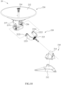
- FIG. 4 is a perspective view schematically illustrating a structure of a pedestal according to an example embodiment
- FIG. 5 is an exploded perspective view schematically illustrating the structure of the pedestal of FIG. 4 .
- the pedestal 10 may include a first supporter 110, a second supporter 120, and the tracker 130.
- the second supporter 120 is configured to have a tilted azimuth axis TAZ of about 53 degrees with respect to a reference plane on which the first supporter 110 is installed.
- the first supporter 110 is installed on the reference plane and configured to support the second supporter 120 and the tracker 130.
- the first supporter 110 may include a first frame 112 having an inclined surface on which the second supporter 120 is installed and a first driver 114 positioned opposite to the second supporter 120 based on the inclined surface of the first frame 112 and coupled to a bearing assembly 129 of the second supporter 120.
- a drive shaft of the first driver 114 coincides with the tilted azimuth axis TAZ of the pedestal 10.
- the second supporter 120 is configured to rotate with respect to the tilted azimuth axis TAZ in response to the drive of the first driver 114.
- the second supporter 120 is installed on the first supporter 110 and configured to support the tracker 130.
- the second supporter 120 is configured to rotate with respect to the drive shaft of the first driver 114, that is, the tilted azimuth axis TAZ of the pedestal 10.
- the second supporter 120 may include a second frame 122, a second driver 124, a first balancer 126, nuts 128a and 128b, and the bearing assembly 129.
- the second frame 122 may include a first arm 1221 and a second arm 1222.
- the first arm 1221 may extend in a first direction to enclose the tracker 130
- the second arm 1222 may extend in a second direction to enclose the tracker 130.
- the first arm 1221 and the second arm 1222 may be positioned opposite to each other based on the tracker 130.
- a proximal portion of the first arm 1221 and a proximal portion of the second arm 1222 may be coupled to each other.
- the bearing assembly 129 may be installed provided in the proximal portion of the first arm 1221 and the proximal portion of the second arm 1222 that are coupled to each other.
- a first slot 1223 may be formed in the extension direction of the first arm 1221 at an end portion of the first arm 1221
- a second slot 1224 may be formed in the extension direction of the second arm 1222 at an end portion of the second arm 1222.
- the second driver 124 may be coupled to the second frame 122 and the tracker 130 so that a drive shaft thereof coincides with the elevational axis EL.
- the drive shaft of the second driver 124 may pass through the first nut 128a, be inserted into the first slot 1223 at the end portion of the first arm 1221 such that the first nut 128a is positioned between the second driver 124 and the first arm 1221, and be coupled to a first shaft 1371 provided in a third frame 137 of the tracker 130.
- the first balancer 126 may be positioned opposite to the second driver 124 based on the second frame 122 in consideration of the weight of the second driver 124.
- the first balancer 126 may be coupled to the end portion of the second arm 1222 such that the second nut 128b is positioned between the first balancer 126 and the second arm 1222.
- the second driver 124 may be inserted into the second slot 1224 provided at the end portion of the second arm 1222 and coupled to a second shaft 1372 provided in the third frame 137 of the tracker 130, where the second shaft 1372 is positioned opposite to the first shaft 1371 based on the third frame.
- the first balancer 126 may be coupled to the end portion of the first arm 1221.
- the bearing assembly 129 may be installed in the proximal portion of the first arm 1221 and the proximal portion of the second arm 1222 and coupled to the drive shaft of the first driver 114.
- an inner race of the bearing assembly 129 is fixed, while an outer race thereof is configured to rotate.
- the inner race of the bearing assembly 129 rotates, while the outer race thereof is fixed.
- the tracker 130 is configured to track an object (e.g., satellite) on the field of view.
- the tracker 130 may include a reflecting body 132, a feed horn 134 positioned at the center of the reflecting body 132, a transmitting/receiving device 136 communicating radio wave information with the feed horn 134, the third frame 137 installed on a rear surface of the reflecting body 132, a fourth frame 138 coupled to the third frame 137 and configured to enclose the transmitting/receiving device 136 along with the third frame 137, and a second balancer 139 positioned opposite to the reflecting body 132 based on the transmitting/receiving device 136.
- the weight of the second balancer 139 may be set in consideration of the weight of the transmitting/receiving device 136 and the weight of the fourth frame 138.
- the third frame 137 and the fourth frame 138 may each include arms extending in both directions, where end portions of the arms of the third frame 137 may be coupled to corresponding end portions of the arms of the fourth frame 138, respectively.
- the first shaft 1371 and the second shaft 1372 to which the second driver 124 is to be coupled may be installed respectively in the end portion of the arm of the third frame 137 and the end portion of the arm of the fourth frame 138 that are coupled to each other.
- the reflecting body 132 of the tracker 130 may be configured to rotate with respect to the elevational axis EL in response to the operation of the second driver 124 coupled to the first shaft 1371 or the second shaft 1372.
- the first supporter 110 may have a fixed rotation with respect to the reference plane.
- the pedestal 10 does not rotate against an axis perpendicular to the reference plane.
- the pedestal 10 according to this example embodiment follows a dual-axis drive method where the tracker 130 rotates independently with respect to two axes, the elevational axis EL and the tilted azimuth axis TAZ.
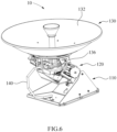
- the pedestal 10 may further include a cable 140 connecting the first supporter 110 and the tracker 130. Ends of the cable 140 may be clamped to the first supporter 110 and the tracker 130.
- the cable 140 may be positioned in a slack configuration in space between the first supporter 110 and the tracker 130 so as to prevent a twist of the cable 140 itself and interference resulting from the operation of the tracker 130.
- the cable 140 may be placed on the same side (for example, on the left side when viewed based on FIG. 6 ) of the first supporter 110 and the tracker 130.
- the cable 140 may include a cable.
- the cable 140 may have any suitable length to maintain the slack configuration.
- the cable 140 may include any suitable elastic material.
- the cable 140 may maintain a substantially slack configuration not to be twisted.
- the cable 140 may maintain a substantially taut configuration not to be twisted.
- such configurations of the cable 140 have structurally simple advantages in helping to prevent a twist of the cable 140 itself and interference resulting from the operation of the tracker 130 and requiring no separate mechanism for wrapping of the cable 140.
- FIG. 9 is a perspective view schematically illustrating a structure of a pedestal according to an example embodiment
- FIG. 10 is an exploded perspective view schematically illustrating the structure of the pedestal of FIG. 9 .
- a pedestal 20 may include a first supporter 210, a second supporter 220, and a tracker 230.
- the second supporter 220 is configured to have a tilted azimuth axis TAZ of about 65 degrees with respect to a reference plane on which the first supporter 210 is installed.
- the first supporter 210 may include a spacer 212 including a plurality of feet extending radially, and a first frame 214 installed on the spacer 212, having a hole through which the second supporter 220 is rotatably coupled thereto, and configured to support the second supporter 220.
- the hole in the first frame 214 may be provided to be aligned with the tilted azimuth axis TAZ of the pedestal 20 and a drive shaft of a first driver (not shown).
- the tracker 230 may include a reflecting body 232, a feed horn 234, a transmitting/receiving device 236, and a third frame 237.
- the third frame 237 may have a housing shape to receiving the transmitting/receiving device 236.
- a first shaft 2371 may be provided on at least one side surface of the third frame 237 such that a second driver (not shown) may be coupled thereto through the first slot 2223.
- a simpler one out of several structures of pedestals having a tilted azimuth axis with respect to a reference plane may be selected in many aspects (e.g., the aspect of structural rigidness, the aspect of driving efficiency of pedestal, and the like).
Landscapes
- Variable-Direction Aerials And Aerial Arrays (AREA)
Description
- The following example embodiments relate to a pedestal with a tilted azimuth axis.
- Devices for transmitting and receiving radio waves through antennas are known in the relevant area. A typical device is configured to have an azimuth axis (AZ axis) that substantially coincides with a zenith line joining the device provided on a reference plane with a zenith. While an antenna of this device tracks an object (e.g., satellite) that transmits and receives radio waves on a field of view FOV, the antenna needs to rotate relatively rapidly when an orientation axis thereof is in a region close to the zenith, rather than when in the other regions within the field of view. Accordingly, a relatively large capacity of power source is required to control the rotation velocity of the antenna while the orientation axis of the antenna is in a region close to the zenith. This phenomenon occurs when the azimuth axis coincides with the zenith line and is generally called the keyhole effect. In consideration of the foregoing, various types of devices are being developed to use a relatively small capacity of power source. For example, a pedestal for tracking an antenna is disclosed in
US Patent Application Publication No. 2014/0299734 . The pedestal disclosed in the publication is configured to be capable of three-axis driving for stabilizing the pointing of a mobile antenna. Such a three-axis driving pedestal requires a complex structure to implement high degrees of freedom. -
US5075682A andUS6243046A andWO2019/173603A1 , which belongs to the state of the art under Article 54(3) EPC, disclose pedestals with inclined azimuth axes. -
JPS63283205 US6198542B1 disclose supporters with inclined rotation axes. - An aspect provides a pedestal configured to use a relatively small capacity of power source through a simple structure while stably tracking a target that transmits and receives radio waves and to use a small capacity of power source at the same time removing a section showing a sharp rise of a drive velocity in a region within a field of view through a structure for avoiding the keyhole effect.
- According to an aspect, there is provided a pedestal including a supporter having an azimuth axis and a pivot on the azimuth axis, and a tracker connected to the pivot and configured to track an object within a field of view, wherein the azimuth axis is tilted with respect to a reference plane on which the supporter is installed in a direction away from a zenith line joining the pivot with a zenith within the field of view, and a tilt angle between the azimuth axis and the reference plane is set to correspond to an orbital angle of the object, wherein the supporter includes a first supporter installed on the reference plane and having an inclined surface that is inclined with respect to the reference plane, and a second supporter installed on the inclined surface and having the azimuth axis and the pivot.
- The tracker has an orientation axis, where the tilt angle may be set such that a singularity point at which the orientation axis of the tracker coincides with the azimuth axis is present in a vicinity of the field of view or outside the field of view.
- The supporter may have a fixed rotation with respect to the reference plane.
- The tracker may be configured to rotate independently with respect to each of the azimuth axis and the pivot.
- The pedestal may further include a cable connecting the first supporter and the tracker, where space may be provided between the first supporter and the tracker to sufficiently receive the cable so as to prevent interference between the cable and the tracker and a twist of the cable while the tracker rotates with respect to the pivot.
- The cable may be placed on a same side of the tracker and the first supporter.
- The cable may be prevented from wrapping while the tracker rotates with respect to the pivot.
- The cable may have a slack configuration while the tracker rotates with respect to the pivot in a first direction, and have a taut configuration while the tracker rotates with respect to the pivot in a second direction which is opposite to the first direction.
- According to example embodiments, a pedestal may have an azimuth axis that is tilted to the outside of a determined field of view and thus, prevent the keyhole effect while being driven within the field of view.
- According to example embodiments, a pedestal may be configured to require no rapid adjustment of a rotation velocity of an antenna while an orientation axis thereof passes through a region close to a zenith.
- According to example embodiments, a pedestal may require relatively low power to rotate an antenna and thus, reduce a capacity of a power source that is used.
- According to example embodiments, a pedestal may be configured in a relatively simple structure to lower the overall weight.
- The effects of the pedestal are not limited to the above-mentioned effects, and other unmentioned effects can be clearly understood from the above description by those having ordinary skill in the technical field to which the present disclosure pertains.
-
-
FIG. 1 schematically illustrates an example of the use of a pedestal according to an example embodiment. -
FIG. 2 is a conceptual diagram to describe a singularity point of a pedestal according to an example embodiment. -
FIGS. 3A to 3E are conceptual diagrams to describe a relationship between a size of a field of view and a tilt angle and a positional change of a singularity point with respect to a change in the tilt angle, the tilt angle of an azimuth axis of a pedestal with respect to a reference plane on which the pedestal is installed, according to an example embodiment. -
FIG. 4 is a perspective view schematically illustrating a structure of a pedestal according to an example embodiment. -
FIG. 5 is an exploded perspective view schematically illustrating the structure of the pedestal ofFIG. 4 . -
FIG. 6 is a side view schematically illustrating a configuration of a cable connecting a supporter and a tracker in a pedestal according to an example embodiment. -
FIG. 7 is a side view schematically illustrating a configuration of a cable when a tracker in a pedestal rotates in a direction toward a reference plane according to an example embodiment. -
FIG. 8 is a side view schematically illustrating a configuration of a cable when a tracker in a pedestal rotates in a direction away from a reference plane according to an example embodiment. -
FIG. 9 is a perspective view schematically illustrating a structure of a pedestal according to an example embodiment. -
FIG. 10 is an exploded perspective view schematically illustrating the structure of the pedestal ofFIG. 9 . - Hereinafter, example embodiments will be described in detail with reference to the illustrative drawings. Regarding the reference numerals assigned to the components in the drawings, it should be noted that the same components will be designated by the same reference numerals, wherever possible, even though they are shown in different drawings. Further, in the following description of the present example embodiments, a detailed description of publicly known configurations or functions incorporated herein will be omitted when it is determined that the detailed description obscures the subject matters of the present example embodiments.
- In addition, the terms first, second, A, B, (a), and (b) may be used to describe constituent elements of the example embodiments. These terms are used only for the purpose of discriminating one constituent element from another constituent element, and the nature, the sequences, or the orders of the constituent elements are not limited by the terms. When one constituent element is described as being "connected", "coupled", or "attached" to another constituent element, it should be understood that one constituent element can be connected or attached directly to another constituent element, and an intervening constituent element can also be "connected", "coupled", or "attached" to the constituent elements.
- The constituent element, which has the same common function as the constituent element included in any one example embodiment, will be described by using the same name in other example embodiments. Unless disclosed to the contrary, the configuration disclosed in any one example embodiment may be applied to other example embodiments, and the specific description of the repeated configuration will be omitted.
-
FIG. 1 schematically illustrates an example of the use of a pedestal according to an example embodiment. - Referring to
FIG. 1 , apedestal 10 according to an example embodiment operates to have an orientation axis OT track an object O on asystem 1 where thepedestal 10 is used. Here, the object O may include, for example, an artificial satellite that transmits and receives radio waves. - The
pedestal 10 has an elevational axis EL, which is a main axis, and a tilted azimuth axis TAZ, where the orientation axis OT of thepedestal 10 is configured to rotate independently with respect to the elevational axis EL and the tilted azimuth axis TAZ. - A field of view FOV refers to a working range in which the orientation axis OT of the
pedestal 10 may track the object O. The field of view FOV is determined based on a range of rotation of the orientation axis OT with respect to the elevational axis EL and the tilted azimuth axis TAZ. For example, the field of view FOV may generally have a conical shape about the position of thepedestal 10. - A zenith ZP refers to a point at which an extension line perpendicular to a reference plane GD on which the
pedestal 10 is installed meets the field of view. Here, the extension line perpendicular to the reference plane GD is defined as a zenith line ZL. - The object O moves along a set orbit on the field of view FOV. Here, an orbital plane including the orbit of the object O and a reference point on the reference plane GD on which the
pedestal 10 is positioned is defined. An orbital angle is defined as an angle θ formed by the orbital plane and a vertical plane VP that passes through the zenith ZP and is perpendicular to the reference plane GD. A tilt angle of the tilted azimuth axis TAZ with respect to the reference plane GD is set to correspond to the orbital angle so as to stably track the object O within the field of view FOV. -
FIG. 2 is a conceptual diagram to describe a singularity point of a pedestal according to an example embodiment. - Referring to
FIG. 2 , thepedestal 10 according to an example embodiment may include atracker 130 having an orientation axis OT that tracks an object. Thetracker 130 may rotate with respect to the elevational axis EL about the pivot, and rotate with respect to the tilted azimuth axis TAZ independently from the rotation with respect to the elevational axis. - The singularity point SP is defined as a point on a celestial body on which the orientation axis OT of the
tracker 130 coincides with the tilted azimuth axis TAZ. While an object O passes through a region in the vicinity of the singularity point SP, a radical change in the rotation direction and/or the rotation velocity of thetracker 130 that tracks the object O, the so-called keyhole effect, may occur. In this case, a power source needs to have a large capacity to drive thetracker 130 having the rotation direction and/or the rotation velocity that changes rapidly, and a large structural rigidness of thepedestal 10 may be required accordingly to support the large-capacity power source. Thus, the singularity point SP may not be present at the center of the field of view where an object O is mainly tracked, but in the vicinity of the field of view or preferably outside the field of view. -
FIGS. 3A to 3E are conceptual diagrams to describe a relationship between a size of a field of view and a tilt angle and a positional change of a singularity point with respect to a change in the tilt angle, the tilt angle of an azimuth axis of a pedestal with respect to a reference plane on which the pedestal is installed, according to an example embodiment. - Referring to
FIG. 3A , aconventional pedestal 10a may have an azimuth axis AZ that is perpendicular to a reference plane GD and coincides with a zenith line ZL. In this example embodiment, a singularity point SP may be positioned on the zenith line ZL. When an object being tracked by thetracker 130 passes through the singularity point SP, the rotation direction and/or the rotation velocity of thetracker 130 may change radically in the vicinity of the singularity point SP based on the azimuth axis AZ. - Referring to
FIGS. 3B to 3E , pedestals 10b, 10c, 10d, and 10e according to example embodiments may have azimuth axes AZs that are tilted with respect to the reference plane GD about 30 degrees, about 53 degrees, about 65 degrees, and about 90 degrees, respectively. Sequentially from the example embodiment ofFIG. 3B to the example embodiment ofFIG. 3E , the singularity point SP positioned on the tilted azimuth axis TAZ is further away from the zenith line ZL, and the size of the field of view FOV further increases. - The
pedestals pedestal 10a having the azimuth axis AZ that coincides with the zenith line ZL, operate using a relatively small capacity of a power source in terms of driving efficiency, and require a reduced structural rigidness to support the power source. -
FIG. 4 is a perspective view schematically illustrating a structure of a pedestal according to an example embodiment, andFIG. 5 is an exploded perspective view schematically illustrating the structure of the pedestal ofFIG. 4 . - Referring to
FIGS. 4 and5 , thepedestal 10 according to an example embodiment may include afirst supporter 110, asecond supporter 120, and thetracker 130. In this example embodiment, thesecond supporter 120 is configured to have a tilted azimuth axis TAZ of about 53 degrees with respect to a reference plane on which thefirst supporter 110 is installed. - The
first supporter 110 is installed on the reference plane and configured to support thesecond supporter 120 and thetracker 130. Thefirst supporter 110 may include afirst frame 112 having an inclined surface on which thesecond supporter 120 is installed and afirst driver 114 positioned opposite to thesecond supporter 120 based on the inclined surface of thefirst frame 112 and coupled to abearing assembly 129 of thesecond supporter 120. A drive shaft of thefirst driver 114 coincides with the tilted azimuth axis TAZ of thepedestal 10. Thesecond supporter 120 is configured to rotate with respect to the tilted azimuth axis TAZ in response to the drive of thefirst driver 114. - The
second supporter 120 is installed on thefirst supporter 110 and configured to support thetracker 130. Thesecond supporter 120 is configured to rotate with respect to the drive shaft of thefirst driver 114, that is, the tilted azimuth axis TAZ of thepedestal 10. Thesecond supporter 120 may include asecond frame 122, asecond driver 124, afirst balancer 126, nuts 128a and 128b, and the bearingassembly 129. - The
second frame 122 may include afirst arm 1221 and asecond arm 1222. Thefirst arm 1221 may extend in a first direction to enclose thetracker 130, and thesecond arm 1222 may extend in a second direction to enclose thetracker 130. Thefirst arm 1221 and thesecond arm 1222 may be positioned opposite to each other based on thetracker 130. A proximal portion of thefirst arm 1221 and a proximal portion of thesecond arm 1222 may be coupled to each other. The bearingassembly 129 may be installed provided in the proximal portion of thefirst arm 1221 and the proximal portion of thesecond arm 1222 that are coupled to each other. Afirst slot 1223 may be formed in the extension direction of thefirst arm 1221 at an end portion of thefirst arm 1221, and asecond slot 1224 may be formed in the extension direction of thesecond arm 1222 at an end portion of thesecond arm 1222. - The
second driver 124 may be coupled to thesecond frame 122 and thetracker 130 so that a drive shaft thereof coincides with the elevational axis EL. In a detailed example embodiment, the drive shaft of thesecond driver 124 may pass through thefirst nut 128a, be inserted into thefirst slot 1223 at the end portion of thefirst arm 1221 such that thefirst nut 128a is positioned between thesecond driver 124 and thefirst arm 1221, and be coupled to afirst shaft 1371 provided in athird frame 137 of thetracker 130. - The
first balancer 126 may be positioned opposite to thesecond driver 124 based on thesecond frame 122 in consideration of the weight of thesecond driver 124. In a detailed example embodiment, thefirst balancer 126 may be coupled to the end portion of thesecond arm 1222 such that thesecond nut 128b is positioned between thefirst balancer 126 and thesecond arm 1222. - Alternatively, the
second driver 124 may be inserted into thesecond slot 1224 provided at the end portion of thesecond arm 1222 and coupled to asecond shaft 1372 provided in thethird frame 137 of thetracker 130, where thesecond shaft 1372 is positioned opposite to thefirst shaft 1371 based on the third frame. In this example embodiment, thefirst balancer 126 may be coupled to the end portion of thefirst arm 1221. - The bearing
assembly 129 may be installed in the proximal portion of thefirst arm 1221 and the proximal portion of thesecond arm 1222 and coupled to the drive shaft of thefirst driver 114. In the example embodiment shown, an inner race of the bearingassembly 129 is fixed, while an outer race thereof is configured to rotate. In an alternative example embodiment not shown, the inner race of the bearingassembly 129 rotates, while the outer race thereof is fixed. - The
tracker 130 is configured to track an object (e.g., satellite) on the field of view. Thetracker 130 may include a reflectingbody 132, afeed horn 134 positioned at the center of the reflectingbody 132, a transmitting/receiving device 136 communicating radio wave information with thefeed horn 134, thethird frame 137 installed on a rear surface of the reflectingbody 132, afourth frame 138 coupled to thethird frame 137 and configured to enclose the transmitting/receiving device 136 along with thethird frame 137, and asecond balancer 139 positioned opposite to the reflectingbody 132 based on the transmitting/receiving device 136. The weight of thesecond balancer 139 may be set in consideration of the weight of the transmitting/receiving device 136 and the weight of thefourth frame 138. - The
third frame 137 and thefourth frame 138 may each include arms extending in both directions, where end portions of the arms of thethird frame 137 may be coupled to corresponding end portions of the arms of thefourth frame 138, respectively. Thefirst shaft 1371 and thesecond shaft 1372 to which thesecond driver 124 is to be coupled may be installed respectively in the end portion of the arm of thethird frame 137 and the end portion of the arm of thefourth frame 138 that are coupled to each other. The reflectingbody 132 of thetracker 130 may be configured to rotate with respect to the elevational axis EL in response to the operation of thesecond driver 124 coupled to thefirst shaft 1371 or thesecond shaft 1372. - In one example embodiment, the
first supporter 110 may have a fixed rotation with respect to the reference plane. In this example embodiment, thepedestal 10 does not rotate against an axis perpendicular to the reference plane. Thepedestal 10 according to this example embodiment follows a dual-axis drive method where thetracker 130 rotates independently with respect to two axes, the elevational axis EL and the tilted azimuth axis TAZ. -
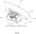
FIG. 6 is a side view schematically illustrating a configuration of a cable connecting a supporter and a tracker in a pedestal according to an example embodiment,FIG. 7 is a side view schematically illustrating a configuration of the cable when the tracker in the pedestal rotates in a direction toward a reference plane according to an example embodiment, andFIG. 8 is a side view schematically illustrating a configuration of the cable when the tracker in the pedestal rotates in a direction away from the reference plane according to an example embodiment. - Referring to
FIG. 6 , thepedestal 10 according to an example embodiment may further include acable 140 connecting thefirst supporter 110 and thetracker 130. Ends of thecable 140 may be clamped to thefirst supporter 110 and thetracker 130. In this example embodiment, thecable 140 may be positioned in a slack configuration in space between thefirst supporter 110 and thetracker 130 so as to prevent a twist of thecable 140 itself and interference resulting from the operation of thetracker 130. In a preferable example embodiment, thecable 140 may be placed on the same side (for example, on the left side when viewed based onFIG. 6 ) of thefirst supporter 110 and thetracker 130. - In an example, the
cable 140 may include a cable. In an example, thecable 140 may have any suitable length to maintain the slack configuration. In an example, thecable 140 may include any suitable elastic material. - Referring to
FIG. 7 , when thetracker 130 rotates downward about the elevational axis EL, thecable 140 may maintain a substantially slack configuration not to be twisted. Referring toFIG. 8 , when thetracker 130 rotates upward about the elevational axis EL, thecable 140 may maintain a substantially taut configuration not to be twisted. - As described above, such configurations of the
cable 140 have structurally simple advantages in helping to prevent a twist of thecable 140 itself and interference resulting from the operation of thetracker 130 and requiring no separate mechanism for wrapping of thecable 140. -
FIG. 9 is a perspective view schematically illustrating a structure of a pedestal according to an example embodiment, andFIG. 10 is an exploded perspective view schematically illustrating the structure of the pedestal ofFIG. 9 . - Referring to
FIGS. 9 and10 , apedestal 20 according to an example embodiment may include afirst supporter 210, asecond supporter 220, and atracker 230. In this example embodiment, thesecond supporter 220 is configured to have a tilted azimuth axis TAZ of about 65 degrees with respect to a reference plane on which thefirst supporter 210 is installed. - The
first supporter 210 may include aspacer 212 including a plurality of feet extending radially, and afirst frame 214 installed on thespacer 212, having a hole through which thesecond supporter 220 is rotatably coupled thereto, and configured to support thesecond supporter 220. The hole in thefirst frame 214 may be provided to be aligned with the tilted azimuth axis TAZ of thepedestal 20 and a drive shaft of a first driver (not shown). - The
second supporter 220 may include asecond frame 222, and thesecond frame 222 may include afirst arm 2221 having afirst slot 2223 and asecond arm 2222 having asecond slot 2224. Thefirst arm 2221 and thesecond arm 2222 may have portions that extend substantially in parallel. - The
tracker 230 may include a reflectingbody 232, afeed horn 234, a transmitting/receiving device 236, and athird frame 237. Thethird frame 237 may have a housing shape to receiving the transmitting/receiving device 236. Afirst shaft 2371 may be provided on at least one side surface of thethird frame 237 such that a second driver (not shown) may be coupled thereto through thefirst slot 2223. - As described above, considering the need to change the structure of a pedestal as a tilt angle formed by an azimuth axis with respect to a reference plane changes, a simpler one out of several structures of pedestals having a tilted azimuth axis with respect to a reference plane may be selected in many aspects (e.g., the aspect of structural rigidness, the aspect of driving efficiency of pedestal, and the like).
- A number of example embodiments have been described above. Nevertheless, it should be understood that various modifications within the scope of the claims may be made to these example embodiments.
Claims (8)
- A pedestal comprising:a supporter (110, 120) having an azimuth axis (TAZ) and a pivot on the azimuth axis (TAZ); anda tracker (130) connected to the pivot and configured to track an object (O) within a field of view (FOV),wherein the azimuth axis (TAZ) is tilted with respect to a reference plane (GD) on which the supporter (110, 120) is installed in a direction away from a zenith line (ZL) joining the pivot with a zenith (ZP) within the field of view (FOV), and the pedestal (10) is configured to set a tilt angle between the azimuth axis (TAZ) and the reference plane (GD) to correspond to an orbital angle of the object (O),characterized in that the supporter (110, 120) comprises:a first supporter (110) installed on the reference plane (GD) and having an inclined surface that is inclined with respect to the reference plane (GD); anda second supporter (120) installed on the inclined surface and having the azimuth axis (TAZ) and the pivot.
- The pedestal of claim 1, wherein the tracker (130) has an orientation axis (OT), where the tilt angle is set such that a singularity point (SP) at which the orientation axis of the tracker (130) coincides with the azimuth axis (TAZ) is present in a vicinity of the field of view (FOV) or outside the field of view (FOV).
- The pedestal of claim 1, wherein the supporter (110, 120) has a fixed rotation with respect to the reference plane (GD).
- The pedestal of claim 1, wherein the tracker (130) is configured to rotate independently with respect to each of the azimuth axis (TAZ) and the pivot.
- The pedestal of claim 1, further comprising:
a cable (140) connecting the first supporter (110) and the tracker (130), where space is provided between the first supporter (110) and the tracker (130) to sufficiently receive the cable (140) so as to prevent interference between the cable (140) and the tracker (130) and a twist of the cable (140) while the tracker (130) rotates with respect to the pivot. - The pedestal of claim 5, wherein the cable (140) is placed on a same side of the tracker (130) and the first supporter (110).
- The pedestal of claim 5, wherein the cable (140) is prevented from wrapping while the tracker (130) rotates with respect to the pivot.
- The pedestal of claim 5, wherein the cable (140) has a slack configuration while the tracker (130) rotates with respect to the pivot in a first direction, and has a taut configuration while the tracker (130) rotates with respect to the pivot in a second direction which is opposite to the first direction.
Applications Claiming Priority (2)
| Application Number | Priority Date | Filing Date | Title |
|---|---|---|---|
| KR1020190006819A KR102103666B1 (en) | 2019-01-18 | 2019-01-18 | Pedestal with tilted azimuth axis |
| PCT/KR2020/000301 WO2020149560A1 (en) | 2019-01-18 | 2020-01-08 | Pedestal including tilted azimuth axis |
Publications (3)
| Publication Number | Publication Date |
|---|---|
| EP3913737A1 EP3913737A1 (en) | 2021-11-24 |
| EP3913737A4 EP3913737A4 (en) | 2022-10-12 |
| EP3913737B1 true EP3913737B1 (en) | 2025-03-05 |
Family
ID=70472245
Family Applications (1)
| Application Number | Title | Priority Date | Filing Date |
|---|---|---|---|
| EP20742073.8A Active EP3913737B1 (en) | 2019-01-18 | 2020-01-08 | Pedestal including tilted azimuth axis |
Country Status (5)
| Country | Link |
|---|---|
| US (1) | US12074379B2 (en) |
| EP (1) | EP3913737B1 (en) |
| KR (1) | KR102103666B1 (en) |
| DK (1) | DK3913737T3 (en) |
| WO (1) | WO2020149560A1 (en) |
Families Citing this family (1)
| Publication number | Priority date | Publication date | Assignee | Title |
|---|---|---|---|---|
| KR102195419B1 (en) * | 2019-09-18 | 2020-12-28 | (주)인텔리안테크놀로지스 | Communication system |
Citations (1)
| Publication number | Priority date | Publication date | Assignee | Title |
|---|---|---|---|---|
| WO2019173603A1 (en) * | 2018-03-08 | 2019-09-12 | Viasat, Inc. | Antenna positioner with eccentric tilt position mechanism |
Family Cites Families (23)
| Publication number | Priority date | Publication date | Assignee | Title |
|---|---|---|---|---|
| FR2252663B1 (en) * | 1973-11-22 | 1978-12-01 | Gueguen Michel | |
| GB1548762A (en) * | 1975-07-23 | 1979-07-18 | Scientific Atlanta | Satelite tracking systems |
| US3999184A (en) * | 1975-07-23 | 1976-12-21 | Scientific-Atlanta, Inc. | Satellite tracking antenna apparatus |
| JPH0666573B2 (en) * | 1987-05-15 | 1994-08-24 | アンリツ株式会社 | Antenna device |
| US5075682A (en) * | 1990-03-30 | 1991-12-24 | Dehnert Douglas K | Antenna mount and method for tracking a satellite moving in an inclined orbit |
| WO1999036989A1 (en) * | 1998-01-13 | 1999-07-22 | Mitsubishi Denki Kabushiki Kaisha | Antenna system |
| US6151496A (en) * | 1998-10-22 | 2000-11-21 | Raytheon Company | System and method of performing soft hand-off with one-dimensional AESA |
| US6198452B1 (en) * | 1999-05-07 | 2001-03-06 | Rockwell Collins, Inc. | Antenna configuration |
| US6285338B1 (en) * | 2000-01-28 | 2001-09-04 | Motorola, Inc. | Method and apparatus for eliminating keyhole problem of an azimuth-elevation gimbal antenna |
| JP2001313506A (en) * | 2000-04-28 | 2001-11-09 | Nec Corp | Antenna direction setting method and satellite broadcast receiving antenna device |
| US6433736B1 (en) * | 2000-11-22 | 2002-08-13 | L-3 Communications Corp. | Method and apparatus for an improved antenna tracking system mounted on an unstable platform |
| JP4102382B2 (en) * | 2005-05-02 | 2008-06-18 | 三菱電機特機システム株式会社 | Weather radar equipment |
| KR20070060630A (en) * | 2005-12-09 | 2007-06-13 | 한국전자통신연구원 | Satellite tracking antenna system |
| KR100857536B1 (en) * | 2007-04-19 | 2008-09-08 | 주식회사 이큐브테크놀로지 | Mobile satellite tracking antenna system and satellite tracking method |
| KR100974534B1 (en) * | 2008-01-24 | 2010-08-10 | 인하대학교 산학협력단 | Pitch-roll based antenna tracking gimbal system for continuous rotation of eye vector |
| US8059048B2 (en) * | 2008-03-11 | 2011-11-15 | Her Majesty The Queen In Right Of Canada, As Represented By The Minister Of Industry, Through The Communications Research Centre Canada | Rotating antenna steering mount |
| KR101209775B1 (en) * | 2011-03-15 | 2012-12-07 | (주)인텔리안테크놀로지스 | Satellite communication antenna |
| DK177464B1 (en) | 2011-12-08 | 2013-06-24 | Spacecom Holding Aps | Pedestal for tracking antenna |
| JP6066573B2 (en) * | 2012-02-29 | 2017-01-25 | セイコーインスツル株式会社 | Balance, watch movement, and watch |
| KR101477199B1 (en) | 2013-07-03 | 2014-12-29 | (주)인텔리안테크놀로지스 | Satellite receiving/transmitting anttena having structure for switching multiple band signal |
| KR101757681B1 (en) | 2016-04-12 | 2017-07-26 | (주)인텔리안테크놀로지스 | Satellite communication antenna capable of receiving multi band signal |
| KR101734217B1 (en) | 2016-06-30 | 2017-05-12 | (주)인텔리안테크놀로지스 | An pedestal apparatus mounted to an antenna being capable of driving biaxially |
| KR102226965B1 (en) | 2019-01-24 | 2021-03-15 | (주)인텔리안테크놀로지스 | Band changer and communication system comprising the same |
-
2019
- 2019-01-18 KR KR1020190006819A patent/KR102103666B1/en active Active
-
2020
- 2020-01-08 US US17/421,315 patent/US12074379B2/en active Active
- 2020-01-08 WO PCT/KR2020/000301 patent/WO2020149560A1/en not_active Ceased
- 2020-01-08 EP EP20742073.8A patent/EP3913737B1/en active Active
- 2020-01-08 DK DK20742073.8T patent/DK3913737T3/en active
Patent Citations (1)
| Publication number | Priority date | Publication date | Assignee | Title |
|---|---|---|---|---|
| WO2019173603A1 (en) * | 2018-03-08 | 2019-09-12 | Viasat, Inc. | Antenna positioner with eccentric tilt position mechanism |
Also Published As
| Publication number | Publication date |
|---|---|
| US20210399416A1 (en) | 2021-12-23 |
| DK3913737T3 (en) | 2025-03-31 |
| WO2020149560A1 (en) | 2020-07-23 |
| US12074379B2 (en) | 2024-08-27 |
| EP3913737A4 (en) | 2022-10-12 |
| EP3913737A1 (en) | 2021-11-24 |
| KR102103666B1 (en) | 2020-04-23 |
Similar Documents
| Publication | Publication Date | Title |
|---|---|---|
| US6531990B2 (en) | Gimbal system for satellite antenna | |
| US6285338B1 (en) | Method and apparatus for eliminating keyhole problem of an azimuth-elevation gimbal antenna | |
| US8305279B2 (en) | Antenna positioner system | |
| EP2996197A1 (en) | Wide scan steerable antenna | |
| US9172128B2 (en) | Antenna pointing system | |
| CA2156402A1 (en) | Drive arrangement for mechanically-steered antennas | |
| US9337535B2 (en) | Low cost, high-performance, switched multi-feed steerable antenna system | |
| US9337536B1 (en) | Electronically steerable SATCOM antenna | |
| US6492955B1 (en) | Steerable antenna system with fixed feed source | |
| US20100245196A1 (en) | Antenna positioning system | |
| EP3913737A1 (en) | Pedestal including tilted azimuth axis | |
| US20110068989A1 (en) | Antenna System with Three Degrees of Freedom | |
| US5279479A (en) | Advanced seeker with large look angle | |
| US7212170B1 (en) | Antenna beam steering via beam-deflecting lens and single-axis mechanical rotator | |
| JPH06196919A (en) | Antenna position regulating equipment | |
| CA2013632C (en) | Antenna pointing device | |
| JPS6022803A (en) | Controller of satellite tracking antenna | |
| EP1099274B1 (en) | Device for antenna systems | |
| JP6068129B2 (en) | Antenna pointing system | |
| WO1993005363A1 (en) | Stabilized antenna system | |
| KR102671172B1 (en) | Sliding pedestal apparatus and antenna comprising the same | |
| US12199348B2 (en) | Communication system with rotatable tracker | |
| JPH04162803A (en) | Antenna array system | |
| JPH10276030A (en) | Directional beam antenna device | |
| US10351265B1 (en) | Rotating gimbal system |
Legal Events
| Date | Code | Title | Description |
|---|---|---|---|
| STAA | Information on the status of an ep patent application or granted ep patent |
Free format text: STATUS: THE INTERNATIONAL PUBLICATION HAS BEEN MADE |
|
| PUAI | Public reference made under article 153(3) epc to a published international application that has entered the european phase |
Free format text: ORIGINAL CODE: 0009012 |
|
| STAA | Information on the status of an ep patent application or granted ep patent |
Free format text: STATUS: REQUEST FOR EXAMINATION WAS MADE |
|
| 17P | Request for examination filed |
Effective date: 20210715 |
|
| AK | Designated contracting states |
Kind code of ref document: A1 Designated state(s): AL AT BE BG CH CY CZ DE DK EE ES FI FR GB GR HR HU IE IS IT LI LT LU LV MC MK MT NL NO PL PT RO RS SE SI SK SM TR |
|
| DAV | Request for validation of the european patent (deleted) | ||
| DAX | Request for extension of the european patent (deleted) | ||
| A4 | Supplementary search report drawn up and despatched |
Effective date: 20220914 |
|
| RIC1 | Information provided on ipc code assigned before grant |
Ipc: H01Q 3/08 20060101ALI20220908BHEP Ipc: H01Q 1/18 20060101ALI20220908BHEP Ipc: H01Q 1/12 20060101AFI20220908BHEP |
|
| GRAP | Despatch of communication of intention to grant a patent |
Free format text: ORIGINAL CODE: EPIDOSNIGR1 |
|
| STAA | Information on the status of an ep patent application or granted ep patent |
Free format text: STATUS: GRANT OF PATENT IS INTENDED |
|
| INTG | Intention to grant announced |
Effective date: 20241024 |
|
| GRAS | Grant fee paid |
Free format text: ORIGINAL CODE: EPIDOSNIGR3 |
|
| GRAA | (expected) grant |
Free format text: ORIGINAL CODE: 0009210 |
|
| STAA | Information on the status of an ep patent application or granted ep patent |
Free format text: STATUS: THE PATENT HAS BEEN GRANTED |
|
| AK | Designated contracting states |
Kind code of ref document: B1 Designated state(s): AL AT BE BG CH CY CZ DE DK EE ES FI FR GB GR HR HU IE IS IT LI LT LU LV MC MK MT NL NO PL PT RO RS SE SI SK SM TR |
|
| REG | Reference to a national code |
Ref country code: GB Ref legal event code: FG4D |
|
| REG | Reference to a national code |
Ref country code: CH Ref legal event code: EP |
|
| REG | Reference to a national code |
Ref country code: DE Ref legal event code: R096 Ref document number: 602020047217 Country of ref document: DE |
|
| REG | Reference to a national code |
Ref country code: IE Ref legal event code: FG4D |
|
| REG | Reference to a national code |
Ref country code: DK Ref legal event code: T3 Effective date: 20250325 |
|
| REG | Reference to a national code |
Ref country code: NL Ref legal event code: FP |
|
| PG25 | Lapsed in a contracting state [announced via postgrant information from national office to epo] |
Ref country code: RS Free format text: LAPSE BECAUSE OF FAILURE TO SUBMIT A TRANSLATION OF THE DESCRIPTION OR TO PAY THE FEE WITHIN THE PRESCRIBED TIME-LIMIT Effective date: 20250605 |
|
| PG25 | Lapsed in a contracting state [announced via postgrant information from national office to epo] |
Ref country code: FI Free format text: LAPSE BECAUSE OF FAILURE TO SUBMIT A TRANSLATION OF THE DESCRIPTION OR TO PAY THE FEE WITHIN THE PRESCRIBED TIME-LIMIT Effective date: 20250305 |
|
| PG25 | Lapsed in a contracting state [announced via postgrant information from national office to epo] |
Ref country code: ES Free format text: LAPSE BECAUSE OF FAILURE TO SUBMIT A TRANSLATION OF THE DESCRIPTION OR TO PAY THE FEE WITHIN THE PRESCRIBED TIME-LIMIT Effective date: 20250305 |
|
| REG | Reference to a national code |
Ref country code: LT Ref legal event code: MG9D |
|
| PG25 | Lapsed in a contracting state [announced via postgrant information from national office to epo] |
Ref country code: HR Free format text: LAPSE BECAUSE OF FAILURE TO SUBMIT A TRANSLATION OF THE DESCRIPTION OR TO PAY THE FEE WITHIN THE PRESCRIBED TIME-LIMIT Effective date: 20250305 |
|
| PG25 | Lapsed in a contracting state [announced via postgrant information from national office to epo] |
Ref country code: LV Free format text: LAPSE BECAUSE OF FAILURE TO SUBMIT A TRANSLATION OF THE DESCRIPTION OR TO PAY THE FEE WITHIN THE PRESCRIBED TIME-LIMIT Effective date: 20250305 |
|
| PG25 | Lapsed in a contracting state [announced via postgrant information from national office to epo] |
Ref country code: GR Free format text: LAPSE BECAUSE OF FAILURE TO SUBMIT A TRANSLATION OF THE DESCRIPTION OR TO PAY THE FEE WITHIN THE PRESCRIBED TIME-LIMIT Effective date: 20250606 Ref country code: BG Free format text: LAPSE BECAUSE OF FAILURE TO SUBMIT A TRANSLATION OF THE DESCRIPTION OR TO PAY THE FEE WITHIN THE PRESCRIBED TIME-LIMIT Effective date: 20250305 |
|
| REG | Reference to a national code |
Ref country code: AT Ref legal event code: MK05 Ref document number: 1773822 Country of ref document: AT Kind code of ref document: T Effective date: 20250305 |
|
| PG25 | Lapsed in a contracting state [announced via postgrant information from national office to epo] |
Ref country code: SE Free format text: LAPSE BECAUSE OF FAILURE TO SUBMIT A TRANSLATION OF THE DESCRIPTION OR TO PAY THE FEE WITHIN THE PRESCRIBED TIME-LIMIT Effective date: 20250305 |
|
| PG25 | Lapsed in a contracting state [announced via postgrant information from national office to epo] |
Ref country code: SM Free format text: LAPSE BECAUSE OF FAILURE TO SUBMIT A TRANSLATION OF THE DESCRIPTION OR TO PAY THE FEE WITHIN THE PRESCRIBED TIME-LIMIT Effective date: 20250305 |
|
| PG25 | Lapsed in a contracting state [announced via postgrant information from national office to epo] |
Ref country code: PT Free format text: LAPSE BECAUSE OF FAILURE TO SUBMIT A TRANSLATION OF THE DESCRIPTION OR TO PAY THE FEE WITHIN THE PRESCRIBED TIME-LIMIT Effective date: 20250707 |
|
| PG25 | Lapsed in a contracting state [announced via postgrant information from national office to epo] |
Ref country code: PL Free format text: LAPSE BECAUSE OF FAILURE TO SUBMIT A TRANSLATION OF THE DESCRIPTION OR TO PAY THE FEE WITHIN THE PRESCRIBED TIME-LIMIT Effective date: 20250305 Ref country code: IT Free format text: LAPSE BECAUSE OF FAILURE TO SUBMIT A TRANSLATION OF THE DESCRIPTION OR TO PAY THE FEE WITHIN THE PRESCRIBED TIME-LIMIT Effective date: 20250305 |
|
| PG25 | Lapsed in a contracting state [announced via postgrant information from national office to epo] |
Ref country code: AT Free format text: LAPSE BECAUSE OF FAILURE TO SUBMIT A TRANSLATION OF THE DESCRIPTION OR TO PAY THE FEE WITHIN THE PRESCRIBED TIME-LIMIT Effective date: 20250305 |
|
| PG25 | Lapsed in a contracting state [announced via postgrant information from national office to epo] |
Ref country code: CZ Free format text: LAPSE BECAUSE OF FAILURE TO SUBMIT A TRANSLATION OF THE DESCRIPTION OR TO PAY THE FEE WITHIN THE PRESCRIBED TIME-LIMIT Effective date: 20250305 Ref country code: EE Free format text: LAPSE BECAUSE OF FAILURE TO SUBMIT A TRANSLATION OF THE DESCRIPTION OR TO PAY THE FEE WITHIN THE PRESCRIBED TIME-LIMIT Effective date: 20250305 |
|
| PG25 | Lapsed in a contracting state [announced via postgrant information from national office to epo] |
Ref country code: RO Free format text: LAPSE BECAUSE OF FAILURE TO SUBMIT A TRANSLATION OF THE DESCRIPTION OR TO PAY THE FEE WITHIN THE PRESCRIBED TIME-LIMIT Effective date: 20250305 |
|
| PG25 | Lapsed in a contracting state [announced via postgrant information from national office to epo] |
Ref country code: SK Free format text: LAPSE BECAUSE OF FAILURE TO SUBMIT A TRANSLATION OF THE DESCRIPTION OR TO PAY THE FEE WITHIN THE PRESCRIBED TIME-LIMIT Effective date: 20250305 |
|
| PG25 | Lapsed in a contracting state [announced via postgrant information from national office to epo] |
Ref country code: IS Free format text: LAPSE BECAUSE OF FAILURE TO SUBMIT A TRANSLATION OF THE DESCRIPTION OR TO PAY THE FEE WITHIN THE PRESCRIBED TIME-LIMIT Effective date: 20250705 |
|
| REG | Reference to a national code |
Ref country code: DE Ref legal event code: R097 Ref document number: 602020047217 Country of ref document: DE |
|
| PLBE | No opposition filed within time limit |
Free format text: ORIGINAL CODE: 0009261 |
|
| STAA | Information on the status of an ep patent application or granted ep patent |
Free format text: STATUS: NO OPPOSITION FILED WITHIN TIME LIMIT |
|
| PGFP | Annual fee paid to national office [announced via postgrant information from national office to epo] |
Ref country code: DK Payment date: 20251224 Year of fee payment: 7 |
|
| REG | Reference to a national code |
Ref country code: CH Ref legal event code: L10 Free format text: ST27 STATUS EVENT CODE: U-0-0-L10-L00 (AS PROVIDED BY THE NATIONAL OFFICE) Effective date: 20260114 |
|
| 26N | No opposition filed |
Effective date: 20251208 |
|
| PGFP | Annual fee paid to national office [announced via postgrant information from national office to epo] |
Ref country code: NL Payment date: 20260127 Year of fee payment: 7 |
|
| PGFP | Annual fee paid to national office [announced via postgrant information from national office to epo] |
Ref country code: GB Payment date: 20260123 Year of fee payment: 7 |
|
| PGFP | Annual fee paid to national office [announced via postgrant information from national office to epo] |
Ref country code: NO Payment date: 20260123 Year of fee payment: 7 |
|
| PG25 | Lapsed in a contracting state [announced via postgrant information from national office to epo] |
Ref country code: LT Free format text: LAPSE BECAUSE OF FAILURE TO SUBMIT A TRANSLATION OF THE DESCRIPTION OR TO PAY THE FEE WITHIN THE PRESCRIBED TIME-LIMIT Effective date: 20250305 |