EP3913704A1 - Insulating plate for secondary battery, and secondary battery including insulating plate - Google Patents
Insulating plate for secondary battery, and secondary battery including insulating plate Download PDFInfo
- Publication number
- EP3913704A1 EP3913704A1 EP20773604.2A EP20773604A EP3913704A1 EP 3913704 A1 EP3913704 A1 EP 3913704A1 EP 20773604 A EP20773604 A EP 20773604A EP 3913704 A1 EP3913704 A1 EP 3913704A1
- Authority
- EP
- European Patent Office
- Prior art keywords
- insulator
- protrusions
- secondary battery
- electrode assembly
- buffer part
- Prior art date
- Legal status (The legal status is an assumption and is not a legal conclusion. Google has not performed a legal analysis and makes no representation as to the accuracy of the status listed.)
- Pending
Links
Images




Classifications
-
- H—ELECTRICITY
- H01—ELECTRIC ELEMENTS
- H01M—PROCESSES OR MEANS, e.g. BATTERIES, FOR THE DIRECT CONVERSION OF CHEMICAL ENERGY INTO ELECTRICAL ENERGY
- H01M50/00—Constructional details or processes of manufacture of the non-active parts of electrochemical cells other than fuel cells, e.g. hybrid cells
- H01M50/40—Separators; Membranes; Diaphragms; Spacing elements inside cells
- H01M50/471—Spacing elements inside cells other than separators, membranes or diaphragms; Manufacturing processes thereof
- H01M50/477—Spacing elements inside cells other than separators, membranes or diaphragms; Manufacturing processes thereof characterised by their shape
-
- H—ELECTRICITY
- H01—ELECTRIC ELEMENTS
- H01M—PROCESSES OR MEANS, e.g. BATTERIES, FOR THE DIRECT CONVERSION OF CHEMICAL ENERGY INTO ELECTRICAL ENERGY
- H01M50/00—Constructional details or processes of manufacture of the non-active parts of electrochemical cells other than fuel cells, e.g. hybrid cells
- H01M50/50—Current conducting connections for cells or batteries
- H01M50/572—Means for preventing undesired use or discharge
-
- H—ELECTRICITY
- H01—ELECTRIC ELEMENTS
- H01M—PROCESSES OR MEANS, e.g. BATTERIES, FOR THE DIRECT CONVERSION OF CHEMICAL ENERGY INTO ELECTRICAL ENERGY
- H01M10/00—Secondary cells; Manufacture thereof
- H01M10/04—Construction or manufacture in general
-
- H—ELECTRICITY
- H01—ELECTRIC ELEMENTS
- H01M—PROCESSES OR MEANS, e.g. BATTERIES, FOR THE DIRECT CONVERSION OF CHEMICAL ENERGY INTO ELECTRICAL ENERGY
- H01M10/00—Secondary cells; Manufacture thereof
- H01M10/04—Construction or manufacture in general
- H01M10/0422—Cells or battery with cylindrical casing
-
- H—ELECTRICITY
- H01—ELECTRIC ELEMENTS
- H01M—PROCESSES OR MEANS, e.g. BATTERIES, FOR THE DIRECT CONVERSION OF CHEMICAL ENERGY INTO ELECTRICAL ENERGY
- H01M10/00—Secondary cells; Manufacture thereof
- H01M10/04—Construction or manufacture in general
- H01M10/0431—Cells with wound or folded electrodes
-
- H—ELECTRICITY
- H01—ELECTRIC ELEMENTS
- H01M—PROCESSES OR MEANS, e.g. BATTERIES, FOR THE DIRECT CONVERSION OF CHEMICAL ENERGY INTO ELECTRICAL ENERGY
- H01M50/00—Constructional details or processes of manufacture of the non-active parts of electrochemical cells other than fuel cells, e.g. hybrid cells
- H01M50/10—Primary casings; Jackets or wrappings
- H01M50/102—Primary casings; Jackets or wrappings characterised by their shape or physical structure
- H01M50/107—Primary casings; Jackets or wrappings characterised by their shape or physical structure having curved cross-section, e.g. round or elliptic
-
- H—ELECTRICITY
- H01—ELECTRIC ELEMENTS
- H01M—PROCESSES OR MEANS, e.g. BATTERIES, FOR THE DIRECT CONVERSION OF CHEMICAL ENERGY INTO ELECTRICAL ENERGY
- H01M50/00—Constructional details or processes of manufacture of the non-active parts of electrochemical cells other than fuel cells, e.g. hybrid cells
- H01M50/10—Primary casings; Jackets or wrappings
- H01M50/14—Primary casings; Jackets or wrappings for protecting against damage caused by external factors
-
- H—ELECTRICITY
- H01—ELECTRIC ELEMENTS
- H01M—PROCESSES OR MEANS, e.g. BATTERIES, FOR THE DIRECT CONVERSION OF CHEMICAL ENERGY INTO ELECTRICAL ENERGY
- H01M50/00—Constructional details or processes of manufacture of the non-active parts of electrochemical cells other than fuel cells, e.g. hybrid cells
- H01M50/10—Primary casings; Jackets or wrappings
- H01M50/183—Sealing members
- H01M50/184—Sealing members characterised by their shape or structure
-
- H—ELECTRICITY
- H01—ELECTRIC ELEMENTS
- H01M—PROCESSES OR MEANS, e.g. BATTERIES, FOR THE DIRECT CONVERSION OF CHEMICAL ENERGY INTO ELECTRICAL ENERGY
- H01M50/00—Constructional details or processes of manufacture of the non-active parts of electrochemical cells other than fuel cells, e.g. hybrid cells
- H01M50/10—Primary casings; Jackets or wrappings
- H01M50/183—Sealing members
- H01M50/186—Sealing members characterised by the disposition of the sealing members
-
- H—ELECTRICITY
- H01—ELECTRIC ELEMENTS
- H01M—PROCESSES OR MEANS, e.g. BATTERIES, FOR THE DIRECT CONVERSION OF CHEMICAL ENERGY INTO ELECTRICAL ENERGY
- H01M50/00—Constructional details or processes of manufacture of the non-active parts of electrochemical cells other than fuel cells, e.g. hybrid cells
- H01M50/10—Primary casings; Jackets or wrappings
- H01M50/183—Sealing members
- H01M50/19—Sealing members characterised by the material
- H01M50/191—Inorganic material
-
- H—ELECTRICITY
- H01—ELECTRIC ELEMENTS
- H01M—PROCESSES OR MEANS, e.g. BATTERIES, FOR THE DIRECT CONVERSION OF CHEMICAL ENERGY INTO ELECTRICAL ENERGY
- H01M50/00—Constructional details or processes of manufacture of the non-active parts of electrochemical cells other than fuel cells, e.g. hybrid cells
- H01M50/10—Primary casings; Jackets or wrappings
- H01M50/183—Sealing members
- H01M50/19—Sealing members characterised by the material
- H01M50/193—Organic material
-
- H—ELECTRICITY
- H01—ELECTRIC ELEMENTS
- H01M—PROCESSES OR MEANS, e.g. BATTERIES, FOR THE DIRECT CONVERSION OF CHEMICAL ENERGY INTO ELECTRICAL ENERGY
- H01M50/00—Constructional details or processes of manufacture of the non-active parts of electrochemical cells other than fuel cells, e.g. hybrid cells
- H01M50/10—Primary casings; Jackets or wrappings
- H01M50/183—Sealing members
- H01M50/19—Sealing members characterised by the material
- H01M50/197—Sealing members characterised by the material having a layered structure
-
- H—ELECTRICITY
- H01—ELECTRIC ELEMENTS
- H01M—PROCESSES OR MEANS, e.g. BATTERIES, FOR THE DIRECT CONVERSION OF CHEMICAL ENERGY INTO ELECTRICAL ENERGY
- H01M50/00—Constructional details or processes of manufacture of the non-active parts of electrochemical cells other than fuel cells, e.g. hybrid cells
- H01M50/10—Primary casings; Jackets or wrappings
- H01M50/183—Sealing members
- H01M50/19—Sealing members characterised by the material
- H01M50/198—Sealing members characterised by the material characterised by physical properties, e.g. adhesiveness or hardness
-
- H—ELECTRICITY
- H01—ELECTRIC ELEMENTS
- H01M—PROCESSES OR MEANS, e.g. BATTERIES, FOR THE DIRECT CONVERSION OF CHEMICAL ENERGY INTO ELECTRICAL ENERGY
- H01M50/00—Constructional details or processes of manufacture of the non-active parts of electrochemical cells other than fuel cells, e.g. hybrid cells
- H01M50/40—Separators; Membranes; Diaphragms; Spacing elements inside cells
- H01M50/471—Spacing elements inside cells other than separators, membranes or diaphragms; Manufacturing processes thereof
- H01M50/474—Spacing elements inside cells other than separators, membranes or diaphragms; Manufacturing processes thereof characterised by their position inside the cells
-
- H—ELECTRICITY
- H01—ELECTRIC ELEMENTS
- H01M—PROCESSES OR MEANS, e.g. BATTERIES, FOR THE DIRECT CONVERSION OF CHEMICAL ENERGY INTO ELECTRICAL ENERGY
- H01M50/00—Constructional details or processes of manufacture of the non-active parts of electrochemical cells other than fuel cells, e.g. hybrid cells
- H01M50/40—Separators; Membranes; Diaphragms; Spacing elements inside cells
- H01M50/471—Spacing elements inside cells other than separators, membranes or diaphragms; Manufacturing processes thereof
- H01M50/48—Spacing elements inside cells other than separators, membranes or diaphragms; Manufacturing processes thereof characterised by the material
- H01M50/486—Organic material
-
- H—ELECTRICITY
- H01—ELECTRIC ELEMENTS
- H01M—PROCESSES OR MEANS, e.g. BATTERIES, FOR THE DIRECT CONVERSION OF CHEMICAL ENERGY INTO ELECTRICAL ENERGY
- H01M50/00—Constructional details or processes of manufacture of the non-active parts of electrochemical cells other than fuel cells, e.g. hybrid cells
- H01M50/50—Current conducting connections for cells or batteries
- H01M50/572—Means for preventing undesired use or discharge
- H01M50/584—Means for preventing undesired use or discharge for preventing incorrect connections inside or outside the batteries
- H01M50/586—Means for preventing undesired use or discharge for preventing incorrect connections inside or outside the batteries inside the batteries, e.g. incorrect connections of electrodes
-
- H—ELECTRICITY
- H01—ELECTRIC ELEMENTS
- H01M—PROCESSES OR MEANS, e.g. BATTERIES, FOR THE DIRECT CONVERSION OF CHEMICAL ENERGY INTO ELECTRICAL ENERGY
- H01M50/00—Constructional details or processes of manufacture of the non-active parts of electrochemical cells other than fuel cells, e.g. hybrid cells
- H01M50/50—Current conducting connections for cells or batteries
- H01M50/572—Means for preventing undesired use or discharge
- H01M50/584—Means for preventing undesired use or discharge for preventing incorrect connections inside or outside the batteries
- H01M50/59—Means for preventing undesired use or discharge for preventing incorrect connections inside or outside the batteries characterised by the protection means
- H01M50/593—Spacers; Insulating plates
-
- H—ELECTRICITY
- H01—ELECTRIC ELEMENTS
- H01M—PROCESSES OR MEANS, e.g. BATTERIES, FOR THE DIRECT CONVERSION OF CHEMICAL ENERGY INTO ELECTRICAL ENERGY
- H01M2200/00—Safety devices for primary or secondary batteries
-
- H—ELECTRICITY
- H01—ELECTRIC ELEMENTS
- H01M—PROCESSES OR MEANS, e.g. BATTERIES, FOR THE DIRECT CONVERSION OF CHEMICAL ENERGY INTO ELECTRICAL ENERGY
- H01M50/00—Constructional details or processes of manufacture of the non-active parts of electrochemical cells other than fuel cells, e.g. hybrid cells
- H01M50/10—Primary casings; Jackets or wrappings
- H01M50/172—Arrangements of electric connectors penetrating the casing
- H01M50/174—Arrangements of electric connectors penetrating the casing adapted for the shape of the cells
- H01M50/176—Arrangements of electric connectors penetrating the casing adapted for the shape of the cells for prismatic or rectangular cells
-
- H—ELECTRICITY
- H01—ELECTRIC ELEMENTS
- H01M—PROCESSES OR MEANS, e.g. BATTERIES, FOR THE DIRECT CONVERSION OF CHEMICAL ENERGY INTO ELECTRICAL ENERGY
- H01M50/00—Constructional details or processes of manufacture of the non-active parts of electrochemical cells other than fuel cells, e.g. hybrid cells
- H01M50/10—Primary casings; Jackets or wrappings
- H01M50/172—Arrangements of electric connectors penetrating the casing
- H01M50/174—Arrangements of electric connectors penetrating the casing adapted for the shape of the cells
- H01M50/179—Arrangements of electric connectors penetrating the casing adapted for the shape of the cells for cells having curved cross-section, e.g. round or elliptic
-
- Y—GENERAL TAGGING OF NEW TECHNOLOGICAL DEVELOPMENTS; GENERAL TAGGING OF CROSS-SECTIONAL TECHNOLOGIES SPANNING OVER SEVERAL SECTIONS OF THE IPC; TECHNICAL SUBJECTS COVERED BY FORMER USPC CROSS-REFERENCE ART COLLECTIONS [XRACs] AND DIGESTS
- Y02—TECHNOLOGIES OR APPLICATIONS FOR MITIGATION OR ADAPTATION AGAINST CLIMATE CHANGE
- Y02E—REDUCTION OF GREENHOUSE GAS [GHG] EMISSIONS, RELATED TO ENERGY GENERATION, TRANSMISSION OR DISTRIBUTION
- Y02E60/00—Enabling technologies; Technologies with a potential or indirect contribution to GHG emissions mitigation
- Y02E60/10—Energy storage using batteries
-
- Y—GENERAL TAGGING OF NEW TECHNOLOGICAL DEVELOPMENTS; GENERAL TAGGING OF CROSS-SECTIONAL TECHNOLOGIES SPANNING OVER SEVERAL SECTIONS OF THE IPC; TECHNICAL SUBJECTS COVERED BY FORMER USPC CROSS-REFERENCE ART COLLECTIONS [XRACs] AND DIGESTS
- Y02—TECHNOLOGIES OR APPLICATIONS FOR MITIGATION OR ADAPTATION AGAINST CLIMATE CHANGE
- Y02P—CLIMATE CHANGE MITIGATION TECHNOLOGIES IN THE PRODUCTION OR PROCESSING OF GOODS
- Y02P70/00—Climate change mitigation technologies in the production process for final industrial or consumer products
- Y02P70/50—Manufacturing or production processes characterised by the final manufactured product
Definitions
- the present invention relates to an insulator for a secondary battery and a secondary battery including the same, and more particularly, to an insulator for a secondary battery, which minimizes an impact applied to an electrode assembly when compared to the related art and a secondary battery including the insulator.
- Secondary batteries that are repetitively chargeable and dischargeable may be divided into pouch type secondary batteries, cylindrical type secondary batteries, and prismatic type secondary batteries according to their structures.
- An electrode assembly having a structure in which electrodes and separators are alternately disposed is provided in a secondary battery, and an insulator may be provided on an upper or lower portion of the electrode assembly.
- the insulator serves to electrically insulate the electrode assembly from other components.
- an impact is applied to the electrode assembly due to collision between the insulator and the electrode assembly and collision between the electrode assembly and other components that are adjacent to the electrode assembly while the secondary battery is used.
- the secondary battery is deteriorated in durability due to an impact that is continuously applied to the electrode assembly.
- an electrode tab of the electrode assembly is separated from its original position to cause an abnormal operation of the secondary battery.
- an object to be achieved by the present invention is to improve durability of a secondary battery by minimizing an impact applied to the electrode assembly due to an external impact or vibration.
- an insulator for a secondary battery includes: a body part configured to define a body; and a buffer part adhering to a top surface of the body part, wherein the buffer part includes a plurality of protrusions that protrude upward, and the body part is made of a material different from that of the buffer part.
- the buffer part may be made of a material having elasticity.
- the buffer part may include polybutylene terephthalate, polypropylene, perfluoroalkoxy, or a rubber material.
- a horizontal cross-section of each of the plurality of protrusions may have an elongated rod shape.
- a horizontal cross-section of each of the plurality of protrusions may have a circular or oval shape.
- the plurality of protrusions are connected to each other by a lower region of the buffer part, the plurality of protrusions may be integrally provided.
- the plurality of protrusions may be provided separately from each other.
- An upper area of a surface of each of the plurality of protrusions may have a curved shape.
- the plurality of protrusions may include: first protrusions in which the rod shape in the horizontal cross-section extends in a first direction (D1); and second protrusions in which the rod shape in the horizontal cross-section extends in a second direction (D2).
- the first direction (D1) and the second direction (D2) may be perpendicular to each other.
- a secondary battery includes: a battery can having a structure in which an upper portion is opened; a top cap coupled to the upper portion of the battery can; an electrode assembly accommodated in the battery can; and the insulator for the secondary battery, which is provided to face a top or bottom surface of the electrode assembly.
- the insulator may include: an upper insulator facing the top surface of the electrode assembly; and a lower insulator facing the bottom surface of the electrode assembly, wherein each of the plurality of protrusions of the upper insulator and the plurality of protrusions of the lower insulator may be provided to face the electrode assembly.
- the impact applied to the electrode assembly due to the external impact or vibration may be minimized to improve the durability of the secondary battery.
- the secondary battery according to the present invention may be applied to a cylindrical type secondary battery or a prismatic type secondary battery.
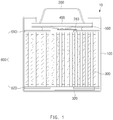
- FIG. 1 is a side cross-sectional view illustrating a structure of a secondary battery according to the present invention.
- a secondary battery 10 may include a battery can 100 having a structure, in which an upper portion is opened, and a top cap 200 coupled to the upper portion of the battery can 100.
- An electrode assembly 300 may be accommodated in the battery can 100.
- the electrode assembly 300 may have a structure in which electrodes and separators are alternately disposed.
- Electrode tabs 310 and 320 each of which has a shape protruding outward may be disposed on the electrode assembly 300.
- FIG. 1 illustrates a case in which a protruding first electrode tab 310 is disposed on an upper portion of the electrode assembly 300, and a protruding second electrode tab 320 is disposed on a lower portion of the electrode assembly 300.
- a current interrupt member 400 may be provided below the top cap 200, and a safety vent 500 may be provided below the current interrupt member 400.
- a peripheral portion of a top surface of the current interrupt member 400 may be provided in close contact with a peripheral portion of a bottom surface of the top cap 200, and a peripheral portion of a top surface of the safety vent 500 may be provided in close contact with a peripheral portion of a bottom surface of the current interrupt member 400.
- the current interrupt member may be, for example, a PTC element.
- the safety vent 500 may be electrically connected to the first electrode tab 310.
- the secondary battery 10 according to the present invention may include an insulator 600 for the secondary battery (hereinafter, referred to as an 'insulator') provided to face the top or bottom surface of the electrode assembly 300.
- an insulator 600 for the secondary battery hereinafter, referred to as an 'insulator'
- the insulator facing the top surface of the electrode assembly 300 is referred to as an upper insulator 610
- the insulator facing the bottom surface of the electrode assembly 300 is referred to as a lower insulator 620.
- FIG. 1 illustrates a case in which both the upper insulator 610 and the lower insulator 620 are provided.
- the secondary battery 10 according to the present invention may be provided with only the upper insulator 610 or the lower insulator 620.
- the upper insulator 610 or the lower insulator 620 may be in close contact with the top or bottom surface of the electrode assembly 300, respectively. Alternatively, the upper insulator 610 or the lower insulator 620 may be spaced a predetermined distance from the electrode assembly 300. As described later, a plurality of protrusions 604a (see FIGS. 2 to 8 ) may be disposed on the insulator 600.
- the upper insulator 610 may be provided so that the plurality of protrusions of the upper insulator 610 face the electrode assembly 300.
- the lower insulator 620 is provided in the secondary battery 10 according to the present invention, the lower insulator may be provided so that the plurality of protrusions 620 of the lower insulator faces the electrode assembly 300.
- FIG. 2 is a perspective view illustrating an example of a structure of an insulator for a secondary battery according to a first embodiment of the present invention.
- an insulator 600 may include a body part 602 defining a body and a buffer part 604 adhering to a top surface of the body part 602.
- the buffer part 604 may be configured to absorb an impact applied to the electrode assembly when an impact or vibration is applied to the secondary battery or the electrode assembly from the outside.
- a hole H may be defined in a central portion of the insulator 600.
- the insulator 600 is configured to electrically insulate the electrode assembly 300 from other components, it is necessary that an area of the insulator 600, which faces or directly contacts the electrode assembly 300, is made of a material having electrical insulating properties.
- the buffer part 604 of the insulator 600 may be made of a material having electrical insulation and elasticity so that the electrode assembly is electrically insulated from other components while effectively absorbing the impact applied to the electrode assembly.
- the buffer part 604 may include or be made of polybutylene terephthalate, polypropylene, perfluoroalkoxy, or a rubber material.
- the material of the body part 602 may be different from that of the buffer part 604.
- the body part 602 may be made of a metal material.
- the body part 602 may be made of stainless steel or aluminum.
- the insulator 600 may normally operate without deforming a shape of the insulator 600.
- the body part 602 is formed in a manner in which a flat metal plate having a constant thickness is bonded to one surface of the buffer part 604 rather than that metal powder is applied on the surface of the buffer part 604 at a thin thickness having a thin film level and then sintered.
- FIG. 3 is an enlarged side cross-sectional view illustrating the example of the structure of the insulator for the secondary battery according to the first embodiment of the present invention
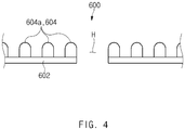
- FIG. 4 is an enlarged side cross-sectional view illustrating another example of the structure of the insulator for the secondary battery according to the first embodiment of the present invention.
- the buffer part 604 of the insulator 600 may include a plurality of protrusions 604a that protrude upward.
- the plurality of protrusions 604a may be configured to face the electrode assembly 300 (see FIG. 1 ).
- the plurality of protrusions 604a of the buffer parts 604 may absorb the impact applied to the electrode assembly to improve durability of the secondary battery.
- the buffer part 604 of the insulator 600 may have a wave-like wave shape. This may be understood that a horizontal cross-section of each of the plurality of protrusions 604a of the buffer part 604 has an elongated rod shape.
- the plurality of protrusions 604a may be connected to each other by a lower region of the buffer part 604 so that the plurality of protrusions 604a are integrally formed.
- the plurality of protrusions 604a may be provided separately from each other. Therefore, as illustrated in FIG. 4 , a top surface of the body part 602 may be exposed to the outside between the plurality of protrusions 604a.
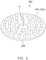
- FIG. 5 is a perspective view illustrating an example of a structure of an insulator for a secondary battery according to a second embodiment of the present invention
- FIG. 6 is an enlarged side cross-sectional view illustrating the example of the structure of the insulator for the secondary battery according to the second embodiment of the present invention
- FIG. 7 is an enlarged side cross-sectional view illustrating another example of the structure of the insulator for the secondary battery according to the second embodiment of the present invention.
- a buffer part 604 of an insulator 600 may have an embossed shape. This may be understood that a horizontal cross-section of each of the plurality of protrusions 640a of the buffer part 604 has a circular or oval shape.
- a plurality of protrusions 604a may be connected to each other by a lower region of the buffer part 604 so that the plurality of protrusions 604a are integrally formed.
- the plurality of protrusions 604a may be provided separately from each other. Therefore, as illustrated in FIG. 7 , a top surface of the body part 602 may be exposed to the outside between the plurality of protrusions 604a.
- FIG. 8 is a perspective view illustrating an example of a structure of an insulator for a secondary battery according to a third embodiment of the present invention.
- a buffer part 604 of an insulator 600 may a wave shape in which waves overlaps each other.
- a horizontal cross-section of a plurality of protrusions 604a of the buffer part 604 has an elongated rod shape
- the plurality of protrusions 604a include first protrusions in which the rod shape in the horizontal cross-section extends in a first direction D1 and second protrusions in which the rod shape in the horizontal cross-section extends in a second direction D2.
- the first direction D1 and the second direction D2 may be perpendicular to each other. That is, the directions in which the rod shapes of the horizontal cross-sections of the first protrusions and the second protrusions extend may be perpendicular to each other.
- An upper area of a surface of each of the plurality of protrusions provided on the buffer part 604 according to the present invention may have a curved surface. Therefore, even if the electrode assembly and the buffer part contact each other, the problem in which the electrode assembly is damaged by the plurality of protrusions may be minimized.
Landscapes
- Chemical & Material Sciences (AREA)
- Chemical Kinetics & Catalysis (AREA)
- Electrochemistry (AREA)
- General Chemical & Material Sciences (AREA)
- Engineering & Computer Science (AREA)
- Manufacturing & Machinery (AREA)
- Inorganic Chemistry (AREA)
- Secondary Cells (AREA)
- Connection Of Batteries Or Terminals (AREA)
- Cell Separators (AREA)
Abstract
Description
- The present application claims the benefit of the priority of
Korean Patent Application 10-2019-0031578, filed on March 20, 2019 - The present invention relates to an insulator for a secondary battery and a secondary battery including the same, and more particularly, to an insulator for a secondary battery, which minimizes an impact applied to an electrode assembly when compared to the related art and a secondary battery including the insulator.
- Secondary batteries that are repetitively chargeable and dischargeable may be divided into pouch type secondary batteries, cylindrical type secondary batteries, and prismatic type secondary batteries according to their structures.
- An electrode assembly having a structure in which electrodes and separators are alternately disposed is provided in a secondary battery, and an insulator may be provided on an upper or lower portion of the electrode assembly.
- The insulator serves to electrically insulate the electrode assembly from other components. According to the related art, there is a problem that an impact is applied to the electrode assembly due to collision between the insulator and the electrode assembly and collision between the electrode assembly and other components that are adjacent to the electrode assembly while the secondary battery is used. In particular, when vibration is applied to the secondary battery from the outside, there is a problem that the secondary battery is deteriorated in durability due to an impact that is continuously applied to the electrode assembly. For example, when the impact or the vibration is applied to the electrode assembly, there is a problem that an electrode tab of the electrode assembly is separated from its original position to cause an abnormal operation of the secondary battery.
- Therefore, an object to be achieved by the present invention is to improve durability of a secondary battery by minimizing an impact applied to the electrode assembly due to an external impact or vibration.
- According to one aspect of the present invention for achieving the above object, an insulator for a secondary battery includes: a body part configured to define a body; and a buffer part adhering to a top surface of the body part, wherein the buffer part includes a plurality of protrusions that protrude upward, and the body part is made of a material different from that of the buffer part.
- The buffer part may be made of a material having elasticity.
- The buffer part may include polybutylene terephthalate, polypropylene, perfluoroalkoxy, or a rubber material.
- A horizontal cross-section of each of the plurality of protrusions may have an elongated rod shape.
- A horizontal cross-section of each of the plurality of protrusions may have a circular or oval shape.
- Since the plurality of protrusions are connected to each other by a lower region of the buffer part, the plurality of protrusions may be integrally provided.
- Since a top surface of the body part is exposed to the outside between the plurality of protrusions, the plurality of protrusions may be provided separately from each other.
- An upper area of a surface of each of the plurality of protrusions may have a curved shape.
- The plurality of protrusions may include: first protrusions in which the rod shape in the horizontal cross-section extends in a first direction (D1); and second protrusions in which the rod shape in the horizontal cross-section extends in a second direction (D2).
- The first direction (D1) and the second direction (D2) may be perpendicular to each other.
- According to another aspect of the prevent invention for achieving the above object, a secondary battery includes: a battery can having a structure in which an upper portion is opened; a top cap coupled to the upper portion of the battery can; an electrode assembly accommodated in the battery can; and the insulator for the secondary battery, which is provided to face a top or bottom surface of the electrode assembly.
- The insulator may include: an upper insulator facing the top surface of the electrode assembly; and a lower insulator facing the bottom surface of the electrode assembly, wherein each of the plurality of protrusions of the upper insulator and the plurality of protrusions of the lower insulator may be provided to face the electrode assembly.
- According to the present invention, the impact applied to the electrode assembly due to the external impact or vibration may be minimized to improve the durability of the secondary battery.
-
-
FIG. 1 is a side cross-sectional view illustrating a structure of a secondary battery according to the present invention. -
FIG. 2 is a perspective view illustrating an example of a structure of an insulator for a secondary battery according to a first embodiment of the present invention. -
FIG. 3 is an enlarged side cross-sectional view illustrating the example of the structure of the insulator for the secondary battery according to the first embodiment of the present invention. -
FIG. 4 is an enlarged side cross-sectional view illustrating another example of the structure of the insulator for the secondary battery according to the first embodiment of the present invention. -
FIG. 5 is a perspective view illustrating an example of a structure of an insulator for a secondary battery according to a second embodiment of the present invention. -
FIG. 6 is an enlarged side cross-sectional view illustrating the example of the structure of the insulator for the secondary battery according to the second embodiment of the present invention. -
FIG. 7 is an enlarged side cross-sectional view illustrating another example of the structure of the insulator for the secondary battery according to the second embodiment of the present invention. -
FIG. 8 is a perspective view illustrating an example of a structure of an insulator for a secondary battery according to a third embodiment of the present invention. - Hereinafter, structures of a secondary battery and an insulator for the secondary battery according to the present invention will be described with reference to the accompanying drawings. The secondary battery according to the present invention may be applied to a cylindrical type secondary battery or a prismatic type secondary battery.
-
FIG. 1 is a side cross-sectional view illustrating a structure of a secondary battery according to the present invention. - As illustrated in
FIG. 1 , asecondary battery 10 according to the present invention may include a battery can 100 having a structure, in which an upper portion is opened, and atop cap 200 coupled to the upper portion of the battery can 100. - An
electrode assembly 300 may be accommodated in the battery can 100. Theelectrode assembly 300 may have a structure in which electrodes and separators are alternately disposed. -
Electrode tabs electrode assembly 300.FIG. 1 illustrates a case in which a protrudingfirst electrode tab 310 is disposed on an upper portion of theelectrode assembly 300, and a protrudingsecond electrode tab 320 is disposed on a lower portion of theelectrode assembly 300. - Continuously, referring to
FIG. 1 , a currentinterrupt member 400 may be provided below thetop cap 200, and asafety vent 500 may be provided below thecurrent interrupt member 400. As illustrated inFIG. 1 , a peripheral portion of a top surface of thecurrent interrupt member 400 may be provided in close contact with a peripheral portion of a bottom surface of thetop cap 200, and a peripheral portion of a top surface of thesafety vent 500 may be provided in close contact with a peripheral portion of a bottom surface of the currentinterrupt member 400. The current interrupt member may be, for example, a PTC element. Thesafety vent 500 may be electrically connected to thefirst electrode tab 310. - The
secondary battery 10 according to the present invention may include aninsulator 600 for the secondary battery (hereinafter, referred to as an 'insulator') provided to face the top or bottom surface of theelectrode assembly 300. Hereinafter, in this specification, the insulator facing the top surface of theelectrode assembly 300 is referred to as anupper insulator 610, and the insulator facing the bottom surface of theelectrode assembly 300 is referred to as alower insulator 620.FIG. 1 illustrates a case in which both theupper insulator 610 and thelower insulator 620 are provided. However, alternatively, thesecondary battery 10 according to the present invention may be provided with only theupper insulator 610 or thelower insulator 620. Also, theupper insulator 610 or thelower insulator 620 may be in close contact with the top or bottom surface of theelectrode assembly 300, respectively. Alternatively, theupper insulator 610 or thelower insulator 620 may be spaced a predetermined distance from theelectrode assembly 300. As described later, a plurality ofprotrusions 604a (seeFIGS. 2 to 8 ) may be disposed on theinsulator 600. When theupper insulator 610 is provided in thesecondary battery 10 according to the present invention, theupper insulator 610 may be provided so that the plurality of protrusions of theupper insulator 610 face theelectrode assembly 300. When thelower insulator 620 is provided in thesecondary battery 10 according to the present invention, the lower insulator may be provided so that the plurality ofprotrusions 620 of the lower insulator faces theelectrode assembly 300. -
FIG. 2 is a perspective view illustrating an example of a structure of an insulator for a secondary battery according to a first embodiment of the present invention. - As illustrated in
FIG. 2 , aninsulator 600 according to the present invention may include abody part 602 defining a body and abuffer part 604 adhering to a top surface of thebody part 602. Thebuffer part 604 may be configured to absorb an impact applied to the electrode assembly when an impact or vibration is applied to the secondary battery or the electrode assembly from the outside. A hole H may be defined in a central portion of theinsulator 600. - Also, since the
insulator 600 is configured to electrically insulate theelectrode assembly 300 from other components, it is necessary that an area of theinsulator 600, which faces or directly contacts theelectrode assembly 300, is made of a material having electrical insulating properties. - Thus, the
buffer part 604 of theinsulator 600 may be made of a material having electrical insulation and elasticity so that the electrode assembly is electrically insulated from other components while effectively absorbing the impact applied to the electrode assembly. For example, thebuffer part 604 may include or be made of polybutylene terephthalate, polypropylene, perfluoroalkoxy, or a rubber material. - In the
insulator 600 according to the present invention, the material of thebody part 602 may be different from that of thebuffer part 604. Thebody part 602 may be made of a metal material. For example, thebody part 602 may be made of stainless steel or aluminum. When thebody part 602 is made of the metal material, since overall rigidity of theinsulator 600 increases, even if an external impact is applied, theinsulator 600 may normally operate without deforming a shape of theinsulator 600. Here, in order to more effectively improve the rigidity of theinsulator 600, it is preferable that thebody part 602 is formed in a manner in which a flat metal plate having a constant thickness is bonded to one surface of thebuffer part 604 rather than that metal powder is applied on the surface of thebuffer part 604 at a thin thickness having a thin film level and then sintered. -
FIG. 3 is an enlarged side cross-sectional view illustrating the example of the structure of the insulator for the secondary battery according to the first embodiment of the present invention, andFIG. 4 is an enlarged side cross-sectional view illustrating another example of the structure of the insulator for the secondary battery according to the first embodiment of the present invention. - As illustrated in
FIGS. 2 and3 , thebuffer part 604 of theinsulator 600 according to the present invention may include a plurality ofprotrusions 604a that protrude upward. The plurality ofprotrusions 604a may be configured to face the electrode assembly 300 (seeFIG. 1 ). When an impact or vibration is applied to the secondary battery or the electrode assembly, the plurality ofprotrusions 604a of thebuffer parts 604 may absorb the impact applied to the electrode assembly to improve durability of the secondary battery. - Here, as illustrated in
FIGS. 2 and3 , according to the first embodiment of the present invention, thebuffer part 604 of theinsulator 600 may have a wave-like wave shape. This may be understood that a horizontal cross-section of each of the plurality ofprotrusions 604a of thebuffer part 604 has an elongated rod shape. - Also, as illustrated in
FIG. 3 , according to an example of the first embodiment of the present invention, the plurality ofprotrusions 604a may be connected to each other by a lower region of thebuffer part 604 so that the plurality ofprotrusions 604a are integrally formed. - However, as illustrated in
FIG. 4 , according to another example of the first embodiment of the present invention, the plurality ofprotrusions 604a may be provided separately from each other. Therefore, as illustrated inFIG. 4 , a top surface of thebody part 602 may be exposed to the outside between the plurality of protrusions 604a. -
FIG. 5 is a perspective view illustrating an example of a structure of an insulator for a secondary battery according to a second embodiment of the present invention, andFIG. 6 is an enlarged side cross-sectional view illustrating the example of the structure of the insulator for the secondary battery according to the second embodiment of the present invention. Also,FIG. 7 is an enlarged side cross-sectional view illustrating another example of the structure of the insulator for the secondary battery according to the second embodiment of the present invention. - As illustrated in
FIGS. 5 and6 , according to the second embodiment of the present invention, abuffer part 604 of aninsulator 600 may have an embossed shape. This may be understood that a horizontal cross-section of each of the plurality of protrusions 640a of thebuffer part 604 has a circular or oval shape. - Also, as illustrated in
FIG. 6 , according to an example of the second embodiment of the present invention, a plurality ofprotrusions 604a may be connected to each other by a lower region of thebuffer part 604 so that the plurality ofprotrusions 604a are integrally formed. - However, as illustrated in
FIG. 7 , according to another example of the second embodiment of the present invention, the plurality ofprotrusions 604a may be provided separately from each other. Therefore, as illustrated inFIG. 7 , a top surface of thebody part 602 may be exposed to the outside between the plurality of protrusions 604a. -
FIG. 8 is a perspective view illustrating an example of a structure of an insulator for a secondary battery according to a third embodiment of the present invention. - As illustrated in
FIG. 8 , according to the third embodiment of the present invention, abuffer part 604 of aninsulator 600 may a wave shape in which waves overlaps each other. This may be understood that a horizontal cross-section of a plurality ofprotrusions 604a of thebuffer part 604 has an elongated rod shape, and the plurality ofprotrusions 604a include first protrusions in which the rod shape in the horizontal cross-section extends in a first direction D1 and second protrusions in which the rod shape in the horizontal cross-section extends in a second direction D2. Here, as illustrated inFIG. 8 , the first direction D1 and the second direction D2 may be perpendicular to each other. That is, the directions in which the rod shapes of the horizontal cross-sections of the first protrusions and the second protrusions extend may be perpendicular to each other. - An upper area of a surface of each of the plurality of protrusions provided on the
buffer part 604 according to the present invention may have a curved surface. Therefore, even if the electrode assembly and the buffer part contact each other, the problem in which the electrode assembly is damaged by the plurality of protrusions may be minimized. - While the embodiments of the present invention have been described with reference to the specific embodiments, it will be apparent to those skilled in the art that various changes and modifications may be made without departing from the spirit and scope of the invention as defined in the following claims.
-
- 10:
- Secondary battery
- 100:
- Battery can
- 200:
- Top cap
- 300:
- Electrode assembly
- 310:
- First electrode tab
- 320:
- Second electrode tab
- 400:
- Current interrupt member
- 500:
- Safety vent
- 600:
- Insulator
- 602:
- Body part
- 604:
- Buffer part
- 604a:
- Protrusion
- 610:
- Upper insulator
- 620:
- Lower insulator
- H:
- Hole
- D1:
- First direction
- D2:
- Second direction
Claims (12)
- An insulator for a secondary battery, comprising:a body part configured to define a body; anda buffer part adhering to a top surface of the body part,wherein the buffer part comprises a plurality of protrusions that protrude upward, andthe body part is made of a material different from that of the buffer part.
- The insulator of claim 1, wherein the buffer part is made of a material having elasticity.
- The insulator of claim 2, wherein the buffer part comprises polybutylene terephthalate, polypropylene, perfluoroalkoxy, or a rubber material.
- The insulator of claim 1, wherein a horizontal cross-section of each of the plurality of protrusions has an elongated rod shape.
- The insulator of claim 1, wherein a horizontal cross-section of each of the plurality of protrusions has a circular or oval shape.
- The insulator of claim 4 or 5, wherein, since the plurality of protrusions are connected to each other by a lower region of the buffer part, the plurality of protrusions are integrally provided.
- The insulator of claim 4 or 5, wherein, since a top surface of the body part is exposed to the outside between the plurality of protrusions, the plurality of protrusions are provided separately from each other.
- The insulator of claim 1, wherein an upper area of a surface of each of the plurality of protrusions has a curved shape.
- The insulator of claim 4, wherein the plurality of protrusions comprise:first protrusions in which the rod shape in the horizontal cross-section extends in a first direction (D1); andsecond protrusions in which the rod shape in the horizontal cross-section extends in a second direction (D2).
- The insulator of claim 9, wherein the first direction (D1) and the second direction (D2) are perpendicular to each other.
- A secondary battery comprising:a battery can having a structure in which an upper portion is opened;a top cap coupled to the upper portion of the battery can;an electrode assembly accommodated in the battery can; andthe insulator of claim 1, which is provided to face a top or bottom surface of the electrode assembly.
- The secondary battery of claim 11, wherein the insulator comprises:an upper insulator facing the top surface of the electrode assembly; anda lower insulator facing the bottom surface of the electrode assembly,wherein each of the plurality of protrusions of the upper insulator and the plurality of protrusions of the lower insulator is provided to face the electrode assembly.
Applications Claiming Priority (2)
| Application Number | Priority Date | Filing Date | Title |
|---|---|---|---|
| KR1020190031578A KR102595153B1 (en) | 2019-03-20 | 2019-03-20 | Insulator for secondary battery and secondary battery including the same |
| PCT/KR2020/003872 WO2020190092A1 (en) | 2019-03-20 | 2020-03-20 | Insulating plate for secondary battery, and secondary battery including insulating plate |
Publications (2)
| Publication Number | Publication Date |
|---|---|
| EP3913704A1 true EP3913704A1 (en) | 2021-11-24 |
| EP3913704A4 EP3913704A4 (en) | 2022-03-16 |
Family
ID=72521118
Family Applications (1)
| Application Number | Title | Priority Date | Filing Date |
|---|---|---|---|
| EP20773604.2A Pending EP3913704A4 (en) | 2019-03-20 | 2020-03-20 | INSULATING PLATE FOR ACCUMULATOR AND ACCUMULATOR MODULE INCLUDING THEREOF |
Country Status (6)
| Country | Link |
|---|---|
| US (1) | US12095117B2 (en) |
| EP (1) | EP3913704A4 (en) |
| JP (1) | JP7230226B2 (en) |
| KR (1) | KR102595153B1 (en) |
| CN (1) | CN113646964A (en) |
| WO (1) | WO2020190092A1 (en) |
Cited By (1)
| Publication number | Priority date | Publication date | Assignee | Title |
|---|---|---|---|---|
| EP4510254A4 (en) * | 2022-09-16 | 2025-10-01 | Contemporary Amperex Technology Hong Kong Ltd | BATTERY CELL, BATTERY AND ELECTRICAL DEVICE |
Families Citing this family (10)
| Publication number | Priority date | Publication date | Assignee | Title |
|---|---|---|---|---|
| DE102019112219A1 (en) * | 2019-05-10 | 2020-11-12 | Johnson Controls Autobatterie Gmbh & Co. Kgaa | Battery case and battery with such |
| EP4195388B1 (en) * | 2021-10-20 | 2025-10-22 | Contemporary Amperex Technology (Hong Kong) Limited | Battery cell, battery, electrical apparatus, and method and device for fabricating battery cell |
| CN121394802B (en) * | 2021-10-20 | 2026-08-07 | 宁德时代新能源科技股份有限公司 | Battery cells, batteries, electrical devices, manufacturing methods and equipment for battery cells |
| WO2024161963A1 (en) * | 2023-01-30 | 2024-08-08 | パナソニックIpマネジメント株式会社 | Non-aqueous electrolyte secondary battery |
| US20260031484A1 (en) * | 2023-01-30 | 2026-01-29 | Panasonic Intellectual Property Management Co., Ltd. | Nonaqueous electrolyte secondary battery |
| KR20240132868A (en) * | 2023-02-27 | 2024-09-04 | 삼성에스디아이 주식회사 | Secondary battery |
| CN119340619B (en) * | 2023-07-18 | 2026-01-30 | 宁德时代新能源科技股份有限公司 | Batteries, spacers and electrical devices |
| KR102891459B1 (en) * | 2024-06-24 | 2025-11-26 | 주식회사 엘지에너지솔루션 | Battery cell, and battery pack and vehicle including the battery cell |
| KR20260077177A (en) * | 2024-11-21 | 2026-05-28 | 주식회사 엘지에너지솔루션 | Battery cell and battery pack and vehicle including the same |
| KR20260118978A (en) * | 2025-01-24 | 2026-07-31 | 주식회사 엘지에너지솔루션 | Battery cell, battery pack and vehicle including the same |
Family Cites Families (21)
| Publication number | Priority date | Publication date | Assignee | Title |
|---|---|---|---|---|
| EP0693792B1 (en) * | 1994-07-19 | 2003-01-08 | Canon Kabushiki Kaisha | Rechargeable batteries having a specific anode and process for the production of them |
| JP4055219B2 (en) * | 1997-04-08 | 2008-03-05 | 松下電器産業株式会社 | Non-aqueous electrolyte secondary battery |
| KR200207949Y1 (en) * | 1998-09-10 | 2001-11-16 | 김순택 | Secondary battery |
| KR100947989B1 (en) * | 2007-11-06 | 2010-03-18 | 삼성에스디아이 주식회사 | Secondary Battery and Manufacturing Method Thereof |
| KR101132162B1 (en) | 2008-04-02 | 2012-04-05 | 주식회사 엘지화학 | Secondary Battery Employed with Bottom Insulator Having Endothermic Material Filled in Grooves |
| US8337572B2 (en) | 2008-06-17 | 2012-12-25 | Panasonic Corporation | Battery and method for producing the same |
| KR101002506B1 (en) | 2008-09-18 | 2010-12-17 | 삼성에스디아이 주식회사 | Lithium secondary battery |
| US9017860B2 (en) | 2009-02-26 | 2015-04-28 | Samsung Sdi Co., Ltd. | Cylinder type secondary battery |
| KR101097255B1 (en) | 2009-11-30 | 2011-12-21 | 삼성에스디아이 주식회사 | Secondary battery |
| KR20120066916A (en) | 2010-12-15 | 2012-06-25 | 주식회사 엘지화학 | Secondary battery of excellent productability and safety |
| KR101300585B1 (en) | 2011-06-30 | 2013-08-27 | 주식회사 엘지화학 | Secondary Battery Comprising Insulator |
| KR101403383B1 (en) | 2011-10-20 | 2014-06-11 | 주식회사 엘지화학 | Cylindrical Secondary Battery of Improved Safety |
| JP5906962B2 (en) * | 2012-06-28 | 2016-04-20 | Nok株式会社 | Secondary battery module cell holder |
| JP2014072050A (en) | 2012-09-28 | 2014-04-21 | Sanyo Electric Co Ltd | Nonaqueous electrolyte secondary battery |
| KR20160015898A (en) | 2014-08-01 | 2016-02-15 | 주식회사 엘지화학 | Cylindrical secondary battery having bottom insulator to improve safety of battery |
| JP2017059506A (en) | 2015-09-18 | 2017-03-23 | リチウム エナジー アンド パワー ゲゼルシャフト ミット ベシュレンクテル ハフッング ウント コンパニー コマンディトゲゼルシャフトLithium Energy and Power GmbH & Co. KG | Power storage device and manufacturing method thereof |
| KR102106999B1 (en) | 2016-04-25 | 2020-05-06 | 주식회사 엘지화학 | Battery Cell with Improved Insulative Performance of Electrode Lead and Excellent Productivity on Standardized Structure and Battery Pack Comprising the Same |
| KR102116941B1 (en) | 2016-08-29 | 2020-05-29 | 주식회사 엘지화학 | Secondary Battery Comprising Insulator Assembly Capable of Suppressing Damage to Electrode Assembly Caused by External Force |
| KR102509709B1 (en) | 2017-04-26 | 2023-03-15 | 주식회사 엘지에너지솔루션 | Insulating Member and Cylindrical Battery Cell Comprising Insulating Member |
| CN207602713U (en) | 2017-12-28 | 2018-07-10 | 东莞市赛洋新能源科技有限公司 | A battery pack and a lithium battery with the battery pack |
| CN208127280U (en) | 2018-04-27 | 2018-11-20 | 宁德时代新能源科技股份有限公司 | Secondary cell |
-
2019
- 2019-03-20 KR KR1020190031578A patent/KR102595153B1/en active Active
-
2020
- 2020-03-20 JP JP2021547783A patent/JP7230226B2/en active Active
- 2020-03-20 US US17/429,936 patent/US12095117B2/en active Active
- 2020-03-20 EP EP20773604.2A patent/EP3913704A4/en active Pending
- 2020-03-20 WO PCT/KR2020/003872 patent/WO2020190092A1/en not_active Ceased
- 2020-03-20 CN CN202080012801.3A patent/CN113646964A/en active Pending
Cited By (1)
| Publication number | Priority date | Publication date | Assignee | Title |
|---|---|---|---|---|
| EP4510254A4 (en) * | 2022-09-16 | 2025-10-01 | Contemporary Amperex Technology Hong Kong Ltd | BATTERY CELL, BATTERY AND ELECTRICAL DEVICE |
Also Published As
| Publication number | Publication date |
|---|---|
| EP3913704A4 (en) | 2022-03-16 |
| WO2020190092A1 (en) | 2020-09-24 |
| JP2022521195A (en) | 2022-04-06 |
| US12095117B2 (en) | 2024-09-17 |
| KR102595153B1 (en) | 2023-10-27 |
| KR20200111926A (en) | 2020-10-05 |
| US20220216572A1 (en) | 2022-07-07 |
| JP7230226B2 (en) | 2023-02-28 |
| CN113646964A (en) | 2021-11-12 |
Similar Documents
| Publication | Publication Date | Title |
|---|---|---|
| US12095117B2 (en) | Insulator for secondary battery and secondary battery including the same | |
| EP3641005B1 (en) | Secondary battery and battery module | |
| EP2346110B1 (en) | Recharcheable battery | |
| EP3471166B1 (en) | Cap assembly for a secondary battery and secondary battery | |
| EP2290732B1 (en) | Secondary battery with insulating member | |
| EP2079126B1 (en) | Impact Resistant Battery Pack | |
| US20080131768A1 (en) | Cylindrical secondary battery | |
| US20190109305A1 (en) | Cap assembly for a second battery and second battery | |
| EP3570344B1 (en) | Secondary battery and top cover assembly thereof | |
| JP6308071B2 (en) | Rectangular secondary battery and method for manufacturing the same | |
| US20150207132A1 (en) | Electric storage device including current interruption device | |
| KR20220023100A (en) | Secondary battery | |
| KR101744090B1 (en) | Rechargeable battery having short member | |
| CN208256820U (en) | Secondary cell | |
| EP3333931B1 (en) | Secondary battery | |
| US10741821B2 (en) | Secondary battery | |
| KR20110054661A (en) | Cap up plate and cylindrical secondary battery having same | |
| US20220223987A1 (en) | Cylindrical Secondary Battery Including Positive Electrode Tab Fixing Member | |
| WO2012063733A1 (en) | Battery module | |
| JP6573975B2 (en) | Current interrupt device and power storage device including the same | |
| JP6471735B2 (en) | Secondary battery | |
| KR100274937B1 (en) | The case of lithium ion battery | |
| EP3490035B1 (en) | Secondary battery and method for manufacturing the same | |
| JP2017022113A (en) | Power storage device | |
| JP6905068B2 (en) | Current cutoff device and power storage device |
Legal Events
| Date | Code | Title | Description |
|---|---|---|---|
| STAA | Information on the status of an ep patent application or granted ep patent |
Free format text: STATUS: THE INTERNATIONAL PUBLICATION HAS BEEN MADE |
|
| PUAI | Public reference made under article 153(3) epc to a published international application that has entered the european phase |
Free format text: ORIGINAL CODE: 0009012 |
|
| STAA | Information on the status of an ep patent application or granted ep patent |
Free format text: STATUS: REQUEST FOR EXAMINATION WAS MADE |
|
| 17P | Request for examination filed |
Effective date: 20210816 |
|
| AK | Designated contracting states |
Kind code of ref document: A1 Designated state(s): AL AT BE BG CH CY CZ DE DK EE ES FI FR GB GR HR HU IE IS IT LI LT LU LV MC MK MT NL NO PL PT RO RS SE SI SK SM TR |
|
| A4 | Supplementary search report drawn up and despatched |
Effective date: 20220210 |
|
| RIC1 | Information provided on ipc code assigned before grant |
Ipc: H01M 50/193 20210101ALI20220204BHEP Ipc: H01M 50/186 20210101ALI20220204BHEP Ipc: H01M 50/184 20210101ALI20220204BHEP Ipc: H01M 50/197 20210101ALI20220204BHEP Ipc: H01M 50/191 20210101ALI20220204BHEP Ipc: H01M 50/14 20210101ALI20220204BHEP Ipc: H01M 50/107 20210101ALI20220204BHEP Ipc: H01M 10/04 20060101AFI20220204BHEP |
|
| RAP3 | Party data changed (applicant data changed or rights of an application transferred) |
Owner name: LG ENERGY SOLUTION, LTD. |
|
| DAV | Request for validation of the european patent (deleted) | ||
| DAX | Request for extension of the european patent (deleted) |