EP3913653B1 - Articulated clinch joint for molded case circuit breaker - Google Patents
Articulated clinch joint for molded case circuit breaker Download PDFInfo
- Publication number
- EP3913653B1 EP3913653B1 EP21186119.0A EP21186119A EP3913653B1 EP 3913653 B1 EP3913653 B1 EP 3913653B1 EP 21186119 A EP21186119 A EP 21186119A EP 3913653 B1 EP3913653 B1 EP 3913653B1
- Authority
- EP
- European Patent Office
- Prior art keywords
- component
- movable contact
- assembly
- contact arm
- arm assembly
- Prior art date
- Legal status (The legal status is an assumption and is not a legal conclusion. Google has not performed a legal analysis and makes no representation as to the accuracy of the status listed.)
- Active
Links
- 230000008878 coupling Effects 0.000 claims description 66
- 238000010168 coupling process Methods 0.000 claims description 66
- 238000005859 coupling reaction Methods 0.000 claims description 66
- 239000004020 conductor Substances 0.000 claims description 64
- 238000004891 communication Methods 0.000 description 14
- 238000003475 lamination Methods 0.000 description 9
- 230000000712 assembly Effects 0.000 description 8
- 238000000429 assembly Methods 0.000 description 8
- RYGMFSIKBFXOCR-UHFFFAOYSA-N Copper Chemical compound [Cu] RYGMFSIKBFXOCR-UHFFFAOYSA-N 0.000 description 3
- 229910052802 copper Inorganic materials 0.000 description 3
- 239000010949 copper Substances 0.000 description 3
- 230000001419 dependent effect Effects 0.000 description 2
- 239000000463 material Substances 0.000 description 2
- 238000012545 processing Methods 0.000 description 2
- 238000000926 separation method Methods 0.000 description 2
- 238000012546 transfer Methods 0.000 description 2
- -1 but not limited to Substances 0.000 description 1
- 238000000034 method Methods 0.000 description 1
- 238000012986 modification Methods 0.000 description 1
- 230000004048 modification Effects 0.000 description 1
- 239000012811 non-conductive material Substances 0.000 description 1
- 230000001012 protector Effects 0.000 description 1
- 239000007858 starting material Substances 0.000 description 1
Images


Classifications
-
- H—ELECTRICITY
- H01—ELECTRIC ELEMENTS
- H01H—ELECTRIC SWITCHES; RELAYS; SELECTORS; EMERGENCY PROTECTIVE DEVICES
- H01H71/00—Details of the protective switches or relays covered by groups H01H73/00 - H01H83/00
- H01H71/10—Operating or release mechanisms
-
- H—ELECTRICITY
- H01—ELECTRIC ELEMENTS
- H01H—ELECTRIC SWITCHES; RELAYS; SELECTORS; EMERGENCY PROTECTIVE DEVICES
- H01H71/00—Details of the protective switches or relays covered by groups H01H73/00 - H01H83/00
- H01H71/10—Operating or release mechanisms
- H01H71/12—Automatic release mechanisms with or without manual release
- H01H71/42—Induction-motor, induced-current, or electrodynamic release mechanisms
- H01H71/43—Electrodynamic release mechanisms
-
- H—ELECTRICITY
- H01—ELECTRIC ELEMENTS
- H01H—ELECTRIC SWITCHES; RELAYS; SELECTORS; EMERGENCY PROTECTIVE DEVICES
- H01H71/00—Details of the protective switches or relays covered by groups H01H73/00 - H01H83/00
- H01H71/02—Housings; Casings; Bases; Mountings
-
- H—ELECTRICITY
- H01—ELECTRIC ELEMENTS
- H01H—ELECTRIC SWITCHES; RELAYS; SELECTORS; EMERGENCY PROTECTIVE DEVICES
- H01H2205/00—Movable contacts
- H01H2205/002—Movable contacts fixed to operating part
-
- H—ELECTRICITY
- H01—ELECTRIC ELEMENTS
- H01H—ELECTRIC SWITCHES; RELAYS; SELECTORS; EMERGENCY PROTECTIVE DEVICES
- H01H3/00—Mechanisms for operating contacts
- H01H3/22—Power arrangements internal to the switch for operating the driving mechanism
- H01H3/222—Power arrangements internal to the switch for operating the driving mechanism using electrodynamic repulsion
-
- H—ELECTRICITY
- H01—ELECTRIC ELEMENTS
- H01H—ELECTRIC SWITCHES; RELAYS; SELECTORS; EMERGENCY PROTECTIVE DEVICES
- H01H71/00—Details of the protective switches or relays covered by groups H01H73/00 - H01H83/00
- H01H71/10—Operating or release mechanisms
- H01H71/50—Manual reset mechanisms which may be also used for manual release
- H01H71/52—Manual reset mechanisms which may be also used for manual release actuated by lever
- H01H71/522—Manual reset mechanisms which may be also used for manual release actuated by lever comprising a cradle-mechanism
- H01H71/525—Manual reset mechanisms which may be also used for manual release actuated by lever comprising a cradle-mechanism comprising a toggle between cradle and contact arm and mechanism spring acting between handle and toggle knee
Definitions
- the disclosed and claimed concept relates to a circuit breaker and, more specifically, to a circuit breaker operating mechanism that is structured to resist rebounding from an open, first configuration to a closed, second configuration.
- Circuit switching apparatus include, for example, circuit switching devices, circuit interrupters, such as circuit breakers, network protectors, contactors, motor starters, motor controllers, and other load controllers. Electrical switching apparatus such as circuit interrupters and, in particular, circuit breakers, are well known in the art. Circuit breakers are used to protect electrical circuitry from damage due to an over-current condition, such as an overload condition or a relatively high level short circuit or fault condition. Circuit breakers typically include a number of pairs of separable contacts, an operating mechanism, and a trip unit. The separable contacts move between on open, first configuration and a closed, second configuration. The separable contacts may be operated either manually by way of a handle disposed on the outside of the case or automatically in response to an over-current condition.
- a circuit breaker includes an operating mechanism and a trip unit.
- the operating mechanism is designed to rapidly open and close the separable contacts.
- the operating mechanism is structured to be latched and thereby maintain the contacts in a closed configuration.
- the trip unit is structured to detect over-current conditions. When an over-current condition is detected, the trip unit releases the operating mechanism latch thereby allowing biasing elements to bias the operating mechanism and contacts, to an open configuration.
- a circuit breaker is assigned a size and a "withstand" value.
- the size of the circuit breaker is substantially related to the size of the circuit breaker housing assembly or frame.
- a withstand value at 10 x rated current is typical, or desired, for molded case circuit breakers and miniature circuit breakers.
- Other classes of breaker such as, but not limited to, power circuit breakers and medium voltage breakers, have a withstand value to equal their interruption rating.
- the circuit breaker withstand value involves a balance between blow-off forces generated by electric currents flowing in the breaker and contact forces generated on the movable conductor by the operating mechanism. Thus, as the rated current for a given frame size is increased, the withstand value should be increased a corresponding amount.
- This relationship is, however, limited by the size, shape, configuration, and material properties of the elements of the circuit breaker. That is, as the withstand value is increased, the components of the circuit breaker must become more robust. Typically, the size of the circuit breaker elements is increased so as to increase their strength. The size of the circuit breaker housing assembly, however, limits the increase in the size of the internal elements. That is, if the size of the circuit breaker frame or housing assembly is increased to accommodate the larger components, the circuit breaker could not be considered to be of a selected size.
- US 5,381,121 A discloses a circuit breaker which is remote controllable by an external remote control switch by way of an electronic control unit and an electromagnetic switch drive controlled by the electronic control unit.
- the switch drive switches the electric circuit by a switch lock, which is latched to it and which, during an overload, is unlatched and opened by way of the release of the bimetal of switch drive and, as a result, interrupts the electric circuit.
- an auxiliary switch is actuated, which by way of the electronic control unit turns the remote control switch off and re-latches switch drive with the opened switch lock.
- a movable contact conductor assembly is disclosed wherein loop forces generated in a movable contact arm assembly member are disposed on either side of a primary pivot point for the movable contact arm assembly member.
- the withstand value of the circuit breaker assembly is increased while maintaining the circuit breaker housing assembly size. That is, a circuit breaker assembly of a selected size has a greater withstand value.
- a movable contact arm assembly includes an elongated member with a distal tip, a first end, a medial portion, an actuator coupling second component, a primary pivot second component, a secondary pivot second component, a clinch joint second component, a second end, and a proximal tip.
- the movable contact arm assembly member generates a loop force.
- a loop force first portion is disposed on a first longitudinal side of the movable contact arm assembly member primary pivot second component, and, a loop force second portion is disposed on a second longitudinal side of the movable contact arm assembly member a primary pivot second component.
- the portions of the loop force acting on different sides of the primary pivot counteract each other thereby reducing the force acting on the movable contact arm body as well as the force transferred to the circuit breaker housing assembly.
- the movable contact arm assembly provides a greater withstand value compared to known movable contact arm assemblies.
- a "coupling assembly” includes two or more couplings or coupling components.
- the components of a coupling or coupling assembly are generally not part of the same element or other component. As such, the components of a “coupling assembly” may not be described at the same time in the following description.
- a "coupling” or “coupling component(s)” is one or more component(s) of a coupling assembly. That is, a coupling assembly includes at least two components that are structured to be coupled together. It is understood that the components of a coupling assembly are compatible with each other. For example, in a coupling assembly, if one coupling component is a snap socket, the other coupling component is a snap plug, or, if one coupling component is a bolt, then the other coupling component is a nut.
- a "fastener” is a separate component structured to couple two or more elements.
- a bolt is a “fastener” but a tongue-and-groove coupling is not a “fastener.” That is, the tongue-and-groove elements are part of the elements being coupled and are not a separate component.
- two or more parts or components are “coupled” shall mean that the parts are joined or operate together either directly or indirectly, i.e., through one or more intermediate parts or components, so long as a link occurs.
- directly coupled means that two elements are directly in contact with each other. It is noted that moving parts, such as but not limited to circuit breaker contacts, are “directly coupled” when in one position, e.g., the closed, second position, but are not “directly coupled” when in the open, first position.
- fixedly coupled or “fixed” means that two components are coupled so as to move as one while maintaining a constant orientation relative to each other. Accordingly, when two elements are coupled, all portions of those elements are coupled.
- a description, however, of a specific portion of a first element being coupled to a second element, e.g., an axle first end being coupled to a first wheel, means that the specific portion of the first element is disposed closer to the second element than the other portions thereof.
- the phrase "removably coupled” means that one component is coupled with another component in an essentially temporary manner. That is, the two components are coupled in such a way that the joining or separation of the components is easy and would not damage the components.
- two components secured to each other with a limited number of readily accessible fasteners are "removably coupled” whereas two components that are welded together or joined by difficult to access fasteners are not “removably coupled.”
- a "difficult to access fastener” is one that requires the removal of one or more other components prior to accessing the fastener wherein the "other component” is not an access device such as, but not limited to, a door.
- operatively coupled means that a number of elements or assemblies, each of which is movable between a first position and a second position, or a first configuration and a second configuration, are coupled so that as the first element moves from one position/configuration to the other, the second element moves between positions/configurations as well. It is noted that a first element may be "operatively coupled" to another without the opposite being true.
- “correspond” indicates that two structural components are sized and shaped to be similar to each other and may be coupled with a minimum amount of friction.
- an opening which "corresponds" to a member is sized slightly larger than the member so that the member may pass through the opening with a minimum amount of friction.
- This definition is modified if the two components are to fit "snugly" together. In that situation, the difference between the size of the components is even smaller whereby the amount of friction increases.
- the element defining the opening and/or the component inserted into the opening are made from a deformable or compressible material, the opening may even be slightly smaller than the component being inserted into the opening.
- surfaces, shapes, and lines two, or more, "corresponding" surfaces, shapes, or lines have generally the same size, shape, and contours.
- structured to [verb] means that the identified element or assembly has a structure that is shaped, sized, disposed, coupled and/or configured to perform the identified verb.
- a member that is "structured to move” is movably coupled to another element and includes elements that cause the member to move or the member is otherwise configured to move in response to other elements or assemblies.
- structured to [verb] recites structure and not function.
- a latch release moves between a first position, wherein the latched member is not released, and a second position, wherein the latched member is released.
- the spring-biased latched member moves between a first latched position and a second released position.
- the latch release may move slowly between positions and, until the release is in the second position, the latched member remains in the first position. But, as soon as the latch release reaches the second position, the latched member is released and quickly moves to the second position.
- "corresponding" positions mean that the elements are in the identified first positions at the same time, and, in the identified second positions at the same time.
- the statement that two or more parts or components "engage” one another shall mean that the elements exert a force or bias against one another either directly or through one or more intermediate elements or components. Further, as used herein with regard to moving parts, a moving part may "engage” another element during the motion from one position to another and/or may “engage” another element once in the described position. Thus, it is understood that the statements, “when element A moves to element A first position, element A engages element B," and “when element A is in element A first position, element A engages element B" are equivalent statements and mean that element A either engages element B while moving to element A first position and/or element A either engages element B while in element A first position.
- operatively engage means “engage and move.” That is, "operatively engage” when used in relation to a first component that is structured to move a movable or rotatable second component means that the first component applies a force sufficient to cause the second component to move.
- a screwdriver may be placed into contact with a screw. When no force is applied to the screwdriver, the screwdriver is merely “coupled” to the screw. If an axial force is applied to the screwdriver, the screwdriver is pressed against the screw and “engages” the screw. However, when a rotational force is applied to the screwdriver, the screwdriver "operatively engages" the screw and causes the screw to rotate.
- unitary means a component that is created as a single piece or unit. That is, a component that includes pieces that are created separately and then coupled together as a unit is not a “unitary” component or body.
- number shall mean one or an integer greater than one ( i.e., a plurality).
- association means that the elements are part of the same assembly and/or operate together, or, act upon/with each other in some manner.
- an automobile has four tires and four hub caps. While all the elements are coupled as part of the automobile, it is understood that each hubcap is “associated” with a specific tire.
- [x] moves between its first position and second position
- [y] is structured to move [x] between its first position and second position
- [x] is the name of an element or assembly.
- [x] is an element or assembly that moves between a number of positions
- the pronoun "its” means “[x],” i.e. the named element or assembly that precedes the pronoun "its.”
- in electronic communication is used in reference to communicating a signal via an electromagnetic wave or signal.
- “In electronic communication” includes both hardline and wireless forms of communication; thus, a “data transfer” or “communication method” means that a module transfer data from one computer to another computer (or from one processing assembly to another processing assembly) by physical connections such as USB, Ethernet connections or remotely such as NFC, blue tooth etc. should not be limited to any specific device.
- in electric communication means that a current passes, or can pass, between the identified elements. Being “in electric communication” is further dependent upon an element's position or configuration. For example, in a circuit breaker, a movable contact is “in electric communication” with the fixed contact when the contacts are in a closed position. The same movable contact is not “in electric communication” with the fixed contact when the contacts are in the open position.
- a circuit breaker assembly 10 includes an elongated housing assembly 12 (with the cover removed), a conductor assembly 14, an operating mechanism 16, a trip unit assembly, (not shown) as well as other components.
- the housing assembly 12 is made from a non-conductive material and defines an enclosed space 18 wherein the other components may be disposed.
- the housing assembly enclosed space 18 is, in an exemplary embodiment, generally divided into a number of longitudinal cavities 20 including, or which may also be identified as, a number of elongated channels 22. Other cavities, such as, but not limited to, a cavity for the operating mechanism 16 extend laterally across the longitudinal cavities 20.
- the housing assembly 12, in an exemplary embodiment, includes a number of support members 24.
- the housing assembly support members 24 act as mounting or coupling locations, including but not limited to rotatable coupling locations, for various elements of the circuit breaker 10.
- Each conductor assembly 14 includes a fixed contact conductor assembly 28 and a movable contact conductor assembly 50, discussed below.
- a conductor assembly 14 includes, but is not limited to, a load bus 30, a movable contact 32, (the movable contact conductor assembly 50) a fixed contact 34, and a line bus 36 (the fixed contact conductor assembly 28).
- the contacts are also identified collectively as a "pair of contacts 38.”
- the load bus 30 and movable contact 32 are in electrical communication.
- the fixed contact 34 and the line bus 36 are in electrical communication.
- Each of the load bus 30 and the line bus 36 include a terminal which is disposed outside the housing assembly enclosed space 18.
- the terminals of the load bus 30 and the line bus 36 are coupled to, and in electrical communication with a load and a line, respectively (neither shown).
- the circuit breaker assembly 10 in an exemplary embodiment, includes multiple conductor assemblies 14, e.g. one conductor assembly 14 per pole.
- the operating mechanism 16 is operatively coupled to each movable contact 32 and is structured to move each movable contact 32 between an open, first configuration, wherein each movable contact 32 is spaced from an associated fixed contact 34, and, a closed, second configuration, wherein each movable contact 32 is directly coupled to, and in electrical communication with, the associated fixed contact 34.
- the operating mechanism 16 moves between a first configuration and a second configuration corresponding to the configuration of the movable contact 32.
- the movable contact 32 is a movable contact conductor assembly 50.
- the movable contact conductor assembly 50 includes a conductive base conductor assembly 52 and a movable contact arm assembly 54.
- a cross bar assembly 56 and an operating mechanism actuator 58 are, as used herein, considered part of both the operating mechanism 16 and the movable contact conductor assembly 50.
- the movable contact conductor assembly 50 includes a number of pivot coupling assemblies or otherwise movable coupling assemblies.
- a "coupling assembly” includes two or more couplings or coupling components.
- the pivot/movable coupling assemblies include a pin, rod, or axle (first component) which extends through an opening (second component) in another elements.
- first component the pin, or similar element
- second component the opening
- the pin, or similar element will be described as a "first” component of a coupling assembly and the associated opening will be described as the "second” component of a coupling assembly.
- a “second” component of a coupling assembly may be described before the associated "first” component.
- the conductive base conductor assembly 52 is part of a "clinch joint.” That is, as used herein, a "clinch joint” is a coupling wherein two conductive elements engage each other so that electrical forces generated in the conductive members cannot separate the conductive elements.
- a clinch joint includes a clevis and a generally planar lug wherein in the clevis is a yoke that has tines disposed on either side of the lug.
- the conductive base conductor assembly 52 is a clevis and the movable contact arm assembly 54 is a generally planar body that acts as a lug.
- the conductive base conductor assembly 52 includes a conductive body 60 shaped as a generally planar lug 62 with an opening 63 and a pin.
- the pin which is a cross bar assembly secondary pivot rod 156, is disposed in the opening and extends generally perpendicular to the plane of the lug 62.
- the pin i.e. the cross bar assembly secondary pivot rod 156
- the lug 62 is structured to, and does, engage the movable contact arm assembly 54. That is, the tines 76 of the movable contact arm assembly 54 are biased against the lug 62.
- the conductive base conductor assembly body lug 62 is a clinch joint first component 70.
- the conductive base conductor assembly 52 is coupled, directly coupled, or fixed to, and in electrical communication with, the load bus 30. Further, the conductive base conductor assembly 52 and/or the load bus 30 is coupled, directly coupled, or fixed to the housing assembly 12.
- the movable contact arm assembly 54 includes an elongated member 80 and, in an exemplary embodiment, includes a conductive shunt 130 which creates a magnetic field when a current passes therethrough.
- the movable contact arm assembly member 80 is made of a conductive material, such as, but not limited to copper.
- the movable contact arm assembly member 80 is an assembly defining a clevis 72.
- the movable contact arm assembly member 80 includes a distal tip 82, a first end 84, a medial portion 86, an actuator coupling second component 88, a primary pivot second component 90, a secondary pivot second component 92, a clinch joint second component 94, a second end 96, and a proximal tip 98.
- an “end” includes a portion of the movable contact arm assembly member 80 that extends along a longitudinal axis 100 of the movable contact arm assembly member 80. That is, an “end” is more than the very tip of the movable contact arm assembly member 80.
- the movable contact arm assembly member first end 84 abuts, i.e. is contiguous with, one side of the movable contact arm assembly member medial portion 86 and the movable contact arm assembly member second end 96 abuts the other side of the movable contact arm assembly member medial portion 86.
- the movable contact arm assembly member clevis 72 is disposed at the movable contact arm assembly member second end 96.
- the movable contact arm assembly member 80 includes three conductive, generally planar layers or laminations 74', 74", 74′′′; the two outer laminations 74', 74′′′ extend over the length of the movable contact arm assembly member 80 whereas the middle lamination 74" extends over the movable contact arm assembly member first end 84.
- the two outer laminations 74', 74′′′ at the movable contact arm assembly member second end 96 form two spaced tines 76 located at the movable contact arm assembly member second end 96.
- the two movable contact arm assembly member tines 76 define the movable contact arm assembly member clevis 72.
- each of the movable contact arm assembly member actuator coupling second component 88, movable contact arm assembly member primary pivot second component 90, and movable contact arm assembly member secondary pivot second component 92 are each an opening in the movable contact arm assembly member 80. It is understood that the axes of the openings extend generally perpendicular to the plane of the movable contact arm assembly member laminations 74', 74", 74′′′.
- the movable contact arm assembly member actuator coupling second component 88 is an elongated slot 110 extending generally parallel to the movable contact arm assembly member longitudinal axis 100.
- the movable contact arm assembly member primary pivot second component 90 is a generally circular opening 112.
- the movable contact arm assembly member secondary pivot second component 92 is one of a generally straight slot (not shown), a generally curvilinear slot (not shown), or a generally arcuate slot 114.
- "generally curvilinear” includes elements having multiple curved portions, combinations of curved portions and planar portions, and a plurality of planar portions or segments disposed at angles relative to each other thereby forming a curve.
- "generally arcuate” means a portion of a generally circular shape wherein the circle has a center.
- the movable contact arm assembly member secondary pivot second component 92 is an arcuate slot 114 with a center disposed generally at the movable contact arm assembly member primary pivot second component 90.
- the movable contact arm assembly member actuator coupling second component 88, movable contact arm assembly member primary pivot second component 90, and movable contact arm assembly member secondary pivot second component 92 are disposed in this order along the movable contact arm assembly member longitudinal axis 100. That is, the movable contact arm assembly member actuator coupling second component 88 is disposed between the movable contact arm assembly member distal tip 82 and the movable contact arm assembly member primary pivot second component 90. The movable contact arm assembly member primary pivot second component 90 is disposed between the movable contact arm assembly member actuator coupling second component 88 and the movable contact arm assembly member secondary pivot second component 92.
- the movable contact arm assembly member secondary pivot second component 92 is disposed between the movable contact arm assembly member primary pivot second component 90 and the movable contact arm assembly member proximal tip 98.
- "between” is interpreted broadly and includes locations offset from a line extending between the identified end points.
- the movable contact arm assembly member actuator coupling second component 88 is disposed at the movable contact arm assembly member medial portion 86. Further, the movable contact arm assembly member primary pivot second component 90 is disposed at the movable contact arm assembly member medial portion 86. The movable contact arm assembly member secondary pivot second component 92 is disposed at the movable contact arm assembly member second end 96.
- the movable contact arm assembly member second end 96 includes a leaf spring area 120, i.e. structured to engage a leaf spring 121 or similar construct.
- the movable contact arm assembly member second end leaf spring area 120 is disposed on one of the movable contact arm assembly member tines 76.
- the leaf spring 121 is mounted on a rod 123 extending through the movable contact arm assembly member tines 76.
- the movable contact arm assembly member second end 96, and in an exemplary embodiment, the movable contact arm assembly member second end leaf spring area 120, is a movable contact arm assembly member clinch joint second component 94.
- the current carrying shunt 130 is, in an exemplary embodiment, a band of electrically conducting material, such as but not limited to, copper lamination(s) or copper braid, that is disposed about, i.e. encircling, the planar movable contact arm assembly member 80.
- the conductive shunt 130 is coupled, directly coupled, or fixed to the movable contact arm assembly member medial portion 86. That is, the movable contact arm assembly member medial portion 86 includes the conductive shunt 130.
- the movable contact 32 is coupled, directly coupled, or fixed to the movable contact arm assembly member 80 at the movable contact arm assembly member distal tip 82 and/or movable contact arm assembly member first end 84.
- the cross bar assembly 56 includes an elongated cross bar body 150, a link member 152, a primary pivot rod 154 and a secondary pivot rod 156.
- the longitudinal axis of the cross bar body 150 extends generally perpendicular to the movable contact arm assembly member longitudinal axis 100 and to the plane of the movable contact arm assembly member laminations 74', 74", 74′′′.
- the cross bar assembly link member 152 includes a generally planar body 160.
- the plane of the cross bar assembly link member body 160 extends in a plane that is generally parallel to the movable contact arm assembly member longitudinal axis 100.
- the cross bar body 150 is coupled, directly coupled, or fixed to the cross bar assembly link member body 160.
- the cross bar assembly primary pivot rod 154 extends generally perpendicular to the movable contact arm assembly member longitudinal axis 100 and to the plane of the movable contact arm assembly member laminations 74', 74", 74"', and, generally parallel to the longitudinal axis of the cross bar body 150.
- the cross bar assembly primary pivot rod 154 is coupled, directly coupled, or fixed to the cross bar assembly link member body 160 and is disposed adjacent the cross bar body 150.
- the cross bar assembly primary pivot rod 154 is, in this exemplary embodiment, the cross bar assembly primary pivot first component 170.
- the cross bar assembly secondary pivot rod 156 extends generally perpendicular to the movable contact arm assembly member longitudinal axis 100 and to the plane of the movable contact arm assembly member laminations 74', 74", 74′′′, and, generally parallel to the longitudinal axis of the cross bar body 150.
- the cross bar assembly secondary pivot rod 156 is coupled, directly coupled, or fixed to the cross bar assembly link member body 160 and is spaced from the cross bar body 150. That is, the cross bar assembly primary pivot rod 154 and the cross bar assembly secondary pivot rod 156 are spaced from each other.
- the pin i.e. the cross bar assembly secondary pivot rod 156, is a secondary pivot first component 172.
- the operating mechanism actuator 58 includes an actuator coupling first component 176.
- the actuator coupling first component 176 is a "railroad" (style) wheel axle 180 which supports a wheel 181 ( Figure 5 ).
- the actuator coupling first component 176 could be another part such as, but not limited to, a pin or a cam and follower (neither shown).
- the railroad wheel axle 180 is coupled to the operating mechanism 16 and moves therewith. The axis of the railroad wheel axle 180 extends generally perpendicular to the plane of the movable contact arm assembly member 80.
- the movable contact arm assembly 54 is assembled as follows.
- the conductive base conductor assembly lug 62 is disposed between the movable contact arm assembly member tines 76.
- the movable contact arm assembly member second end leaf spring area 120 is disposed immediately adjacent the conductive base conductor assembly lug 62 .
- the leaf spring 121 is disposed at the movable contact arm assembly member second end leaf spring area 120 on one of the movable contact arm assembly member tines 76.
- the bias of the leaf spring 121 between the mounting rod 123 and the movable contact arm assembly member second end leaf spring area 120 biases the movable contact arm assembly member tines 76 toward each other thereby causing the movable contact arm assembly member tines 76 to engage the conductive base conductor assembly lug 62. That is, the movable contact arm assembly member second end leaf spring area 120 and the clevis tines 76 are biased against the conductive base conductor assembly lug 62.
- movable contact arm assembly member second end leaf spring area 120 which is the movable contact arm assembly member clinch joint second component 94, engages the conductive base conductor assembly lug 62, which is the clinch joint first component 70.
- the engagement of the movable contact arm assembly member second end leaf spring area 120 and the conductive base conductor assembly lug 62 allow for a pivotal, i.e. rotational, movement of the movable contact arm assembly member 80 about the conductive base conductor assembly lug 62. That is, the movable contact arm assembly member 80 pivots generally in the plane of the conductive base conductor assembly lug 62.
- the conductive base conductor assembly body 60 is in electrical communication with the movable contact arm assembly member 80. Further, the movable contact arm assembly member secondary pivot second component 92, as shown, the arcuate slot 114, is disposed on the clevis tines 76.
- the conductive base conductor assembly clinch joint first component 70 is engageably coupled to the movable contact arm assembly member clinch joint second component 94 thereby forming the clinch joint 200, which is a movable coupling.
- the cross bar assembly 56 is rotatably coupled to the conductive base conductor assembly 52 by passing the cross bar assembly secondary pivot first component 172, i.e. cross bar assembly secondary pivot rod 156, through the conductive base conductor assembly lug opening 63, as noted above, as well as the movable contact arm assembly member secondary pivot second component 92, as shown, the arcuate slot 114.
- the cross bar assembly secondary pivot first component 172 and the movable contact arm assembly member secondary pivot second component 92 are pivotally, or rotatably, coupled forming a secondary pivot coupling 202.
- movable contact arm assembly member secondary pivot second component 92 is a slot 114
- movable contact arm assembly member 80 is also movably coupled to the cross bar assembly 56.
- cross bar assembly primary pivot first component 170 i.e. the cross bar assembly primary pivot rod 154
- the movable contact arm assembly member primary pivot second component 90 i.e. the generally circular opening 112.
- the cross bar assembly primary pivot first component 170 and the movable contact arm assembly member primary pivot second component 90 are pivotally, or rotatably, coupled forming a primary pivot coupling 204.
- the actuator coupling first component 176 as shown railroad wheel axle 180, is passed through the movable contact arm assembly member actuator coupling second component 88, as shown, the elongated slot 110.
- the actuator coupling first component 176 and the movable contact arm assembly member actuator coupling second component 88 are movably coupled forming an actuator coupling 206.
- the movable contact arm assembly 54 operates as follows. It is understood that the operating mechanism 16 and the movable contact conductor assembly 50 are initially in the second, closed configuration. In this configuration, a current passes through the conductive base conductor assembly 52 and the movable contact arm assembly member 80 via the conductive shuts 130 (if present) and the clinch joint 200. When an over-current condition occurs, the trip unit assembly detects the over-current condition and causes the operating mechanism 16 and the movable contact arm assembly 54 to move to the first configuration. Before the movable contact arm assembly 54 moves to the first configuration, however, the following occurs.
- the over-current condition i.e. the current passing through the movable contact arm assembly member 80 generates a loop force, i.e. an electro-magnetic force.
- the loop force is represented by arrows in the figures.
- the loop force is generated, generally, along the movable contact arm assembly member longitudinal axis 100 and is directed generally away from the fixed contact 34.
- a loop force first portion 190 is disposed on a first longitudinal side of the movable contact arm assembly member primary pivot second component 90
- a loop force second portion 192 is disposed on a second longitudinal side of the movable contact arm assembly member primary pivot second component 90.
- the loop force is directed from the fixed contact 34, the loop first and second portions 190, 192 counteract each other. That is, the loop force first portion 190 creates a counterclockwise torque about movable contact arm assembly member primary pivot second component 90 whereas the loop force second portion 192 creates a clockwise torque about movable contact arm assembly member primary pivot second component 90.
- the total torque is reduced and the various components, such as but not limited to the housing assembly 12 and the housing assembly support members 24, do not have to withstand a greater torque. That is, the size, shape and configuration of the noted elements solve the problems stated above.
- the loop force first portion 190 has a greater longitudinal length than said loop force second portion 192.
- a force having a "greater longitudinal length” means that the identified portion of the loop force is generated over a length of the movable contact arm assembly member 80 that has a greater length than the length of the movable contact arm assembly member 80 that generates the other portion of the loop force.
- the movable contact 32 moves away from the fixed contact 34 via the movable contact arm assembly member 80 rotating about the primary pivot coupling 204.
- This motion is accommodated by the movable contact arm assembly member secondary pivot second component 92, i.e. generally arcuate slot 114. That is, even though the movable contact arm assembly member 80 is coupled to the cross bar assembly 56 at two, spaced couplings 202, 204, the arcuate slot 114 allows movable contact arm assembly member 80 to move relative the cross bar assembly secondary pivot first component 172, i.e. cross bar assembly secondary pivot rod 156.
- This motion is the initial separation of the movable contact 32 from the fixed contact 34 which, in turn, affects the operating mechanism 16 and the operating mechanism actuator 58, which, in an exemplary embodiment, is the actuator coupling first component 176, i.e. railroad wheel axle 180.
- the operating mechanism 16 Before the movable contact arm assembly member 80 "snaps back," i.e. before there is a counter-rotation about the primary pivot coupling 204, the operating mechanism 16 begins to move to its first configuration. This motion causes the actuator coupling first component 176 to move away from the fixed contact 34. The actuator coupling first component 176 engages the movable contact arm assembly member actuator coupling second component 88 causing the movable contact arm assembly member 80 to rotate about the secondary pivot coupling 202. Further, the motion of the operating mechanism 16 as it moves to its first configuration causes the cross bar assembly 56 to rotate about the secondary pivot coupling 202 as well.
- the primary pivot coupling 204 is moved away from the fixed contact 34.
- the movable contact arm assembly member 80 "snaps back”
- the movable contact arm assembly member distal tip 82 and/or movable contact arm assembly member first end 84 where the movable contact 32 is located moves away from the fixed contact 34.
- the movable contact arm assembly member 80 pivots about the secondary pivot coupling 202
- the movable contact arm assembly member 80 "snaps back" to its initial orientation relative to the cross bar assembly link member 152.
Description
- The disclosed and claimed concept relates to a circuit breaker and, more specifically, to a circuit breaker operating mechanism that is structured to resist rebounding from an open, first configuration to a closed, second configuration.
- Electrical switching apparatus include, for example, circuit switching devices, circuit interrupters, such as circuit breakers, network protectors, contactors, motor starters, motor controllers, and other load controllers. Electrical switching apparatus such as circuit interrupters and, in particular, circuit breakers, are well known in the art. Circuit breakers are used to protect electrical circuitry from damage due to an over-current condition, such as an overload condition or a relatively high level short circuit or fault condition. Circuit breakers typically include a number of pairs of separable contacts, an operating mechanism, and a trip unit. The separable contacts move between on open, first configuration and a closed, second configuration. The separable contacts may be operated either manually by way of a handle disposed on the outside of the case or automatically in response to an over-current condition. That is, a circuit breaker includes an operating mechanism and a trip unit. The operating mechanism is designed to rapidly open and close the separable contacts. The operating mechanism is structured to be latched and thereby maintain the contacts in a closed configuration. The trip unit is structured to detect over-current conditions. When an over-current condition is detected, the trip unit releases the operating mechanism latch thereby allowing biasing elements to bias the operating mechanism and contacts, to an open configuration.
- Generally, a circuit breaker is assigned a size and a "withstand" value. The size of the circuit breaker is substantially related to the size of the circuit breaker housing assembly or frame. Generally, a withstand value at 10 x rated current is typical, or desired, for molded case circuit breakers and miniature circuit breakers. Other classes of breaker, such as, but not limited to, power circuit breakers and medium voltage breakers, have a withstand value to equal their interruption rating. The circuit breaker withstand value involves a balance between blow-off forces generated by electric currents flowing in the breaker and contact forces generated on the movable conductor by the operating mechanism. Thus, as the rated current for a given frame size is increased, the withstand value should be increased a corresponding amount. This relationship is, however, limited by the size, shape, configuration, and material properties of the elements of the circuit breaker. That is, as the withstand value is increased, the components of the circuit breaker must become more robust. Typically, the size of the circuit breaker elements is increased so as to increase their strength. The size of the circuit breaker housing assembly, however, limits the increase in the size of the internal elements. That is, if the size of the circuit breaker frame or housing assembly is increased to accommodate the larger components, the circuit breaker could not be considered to be of a selected size.
- There is, therefore, a need for a circuit breaker having a greater withstand value while maintaining the size of the circuit breaker housing assembly. There is a further need for an improved conductor assembly that may be incorporated into existing circuit breakers.
-
US 5,381,121 A discloses a circuit breaker which is remote controllable by an external remote control switch by way of an electronic control unit and an electromagnetic switch drive controlled by the electronic control unit. The switch drive switches the electric circuit by a switch lock, which is latched to it and which, during an overload, is unlatched and opened by way of the release of the bimetal of switch drive and, as a result, interrupts the electric circuit. During bimetal release, an auxiliary switch is actuated, which by way of the electronic control unit turns the remote control switch off and re-latches switch drive with the opened switch lock. - These needs, and others, are met by at least one embodiment of this invention. The invention is defined by the independent claims. The dependent claims define advantageous embodiments. A movable contact conductor assembly is disclosed wherein loop forces generated in a movable contact arm assembly member are disposed on either side of a primary pivot point for the movable contact arm assembly member. In this configuration, the withstand value of the circuit breaker assembly is increased while maintaining the circuit breaker housing assembly size. That is, a circuit breaker assembly of a selected size has a greater withstand value. Thus, it is noted that the size, shape, and configuration of the elements described below solve the stated problem.
- In an exemplary embodiment, a movable contact arm assembly includes an elongated member with a distal tip, a first end, a medial portion, an actuator coupling second component, a primary pivot second component, a secondary pivot second component, a clinch joint second component, a second end, and a proximal tip. During an over-current event the movable contact arm assembly member generates a loop force. A loop force first portion is disposed on a first longitudinal side of the movable contact arm assembly member primary pivot second component, and, a loop force second portion is disposed on a second longitudinal side of the movable contact arm assembly member a primary pivot second component. In this configuration, the portions of the loop force acting on different sides of the primary pivot counteract each other thereby reducing the force acting on the movable contact arm body as well as the force transferred to the circuit breaker housing assembly. Thus, for a circuit breaker housing assembly of a selected size, the movable contact arm assembly provides a greater withstand value compared to known movable contact arm assemblies.
- A full understanding of the invention can be gained from the following description of the preferred embodiments when read in conjunction with the accompanying drawings in which:
-
Figure 1 is an isometric view of a circuit breaker assembly. -
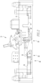
Figure 2 is a side view of a circuit breaker assembly. -
Figure 3 is a side view of a movable contact conductor assembly in a first position. -
Figure 4 is a side view of a movable contact conductor assembly in a second position. -
Figure 5 is a partially exploded view of a conductor assembly. -
Figure 6 is a schematic view of loop forces acting on a movable contact conductor assembly body. - It will be appreciated that the specific elements illustrated in the figures herein and described in the following specification are simply exemplary embodiments of the disclosed concept, which are provided as non-limiting examples solely for the purpose of illustration. Therefore, specific dimensions, orientations, assembly, number of components used, embodiment configurations and other physical characteristics related to the embodiments disclosed herein are not to be considered limiting on the scope of the disclosed concept.
- Directional phrases used herein, such as, for example, clockwise, counterclockwise, left, right, top, bottom, upwards, downwards and derivatives thereof, relate to the orientation of the elements shown in the drawings and are not limiting upon the claims unless expressly recited therein.
- As used herein, the singular form of "a," "an," and "the" include plural references unless the context clearly dictates otherwise.
- As used herein, a "coupling assembly" includes two or more couplings or coupling components. The components of a coupling or coupling assembly are generally not part of the same element or other component. As such, the components of a "coupling assembly" may not be described at the same time in the following description.
- As used herein, a "coupling" or "coupling component(s)" is one or more component(s) of a coupling assembly. That is, a coupling assembly includes at least two components that are structured to be coupled together. It is understood that the components of a coupling assembly are compatible with each other. For example, in a coupling assembly, if one coupling component is a snap socket, the other coupling component is a snap plug, or, if one coupling component is a bolt, then the other coupling component is a nut.
- As used herein, a "fastener" is a separate component structured to couple two or more elements. Thus, for example, a bolt is a "fastener" but a tongue-and-groove coupling is not a "fastener." That is, the tongue-and-groove elements are part of the elements being coupled and are not a separate component.
- As used herein, the statement that two or more parts or components are "coupled" shall mean that the parts are joined or operate together either directly or indirectly, i.e., through one or more intermediate parts or components, so long as a link occurs. As used herein, "directly coupled" means that two elements are directly in contact with each other. It is noted that moving parts, such as but not limited to circuit breaker contacts, are "directly coupled" when in one position, e.g., the closed, second position, but are not "directly coupled" when in the open, first position. As used herein, "fixedly coupled" or "fixed" means that two components are coupled so as to move as one while maintaining a constant orientation relative to each other. Accordingly, when two elements are coupled, all portions of those elements are coupled. A description, however, of a specific portion of a first element being coupled to a second element, e.g., an axle first end being coupled to a first wheel, means that the specific portion of the first element is disposed closer to the second element than the other portions thereof.
- As used herein, the phrase "removably coupled" means that one component is coupled with another component in an essentially temporary manner. That is, the two components are coupled in such a way that the joining or separation of the components is easy and would not damage the components. For example, two components secured to each other with a limited number of readily accessible fasteners are "removably coupled" whereas two components that are welded together or joined by difficult to access fasteners are not "removably coupled." A "difficult to access fastener" is one that requires the removal of one or more other components prior to accessing the fastener wherein the "other component" is not an access device such as, but not limited to, a door.
- As used herein, "operatively coupled" means that a number of elements or assemblies, each of which is movable between a first position and a second position, or a first configuration and a second configuration, are coupled so that as the first element moves from one position/configuration to the other, the second element moves between positions/configurations as well. It is noted that a first element may be "operatively coupled" to another without the opposite being true.
- As used herein, "correspond" indicates that two structural components are sized and shaped to be similar to each other and may be coupled with a minimum amount of friction. Thus, an opening which "corresponds" to a member is sized slightly larger than the member so that the member may pass through the opening with a minimum amount of friction. This definition is modified if the two components are to fit "snugly" together. In that situation, the difference between the size of the components is even smaller whereby the amount of friction increases. If the element defining the opening and/or the component inserted into the opening are made from a deformable or compressible material, the opening may even be slightly smaller than the component being inserted into the opening. With regard to surfaces, shapes, and lines, two, or more, "corresponding" surfaces, shapes, or lines have generally the same size, shape, and contours.
- As used herein, "structured to [verb]" means that the identified element or assembly has a structure that is shaped, sized, disposed, coupled and/or configured to perform the identified verb. For example, a member that is "structured to move" is movably coupled to another element and includes elements that cause the member to move or the member is otherwise configured to move in response to other elements or assemblies. As such, as used herein, "structured to [verb]" recites structure and not function.
- As used herein, and in the phrase " [x] moves between a first position and a second position corresponding to [y] first and second positions," wherein "[x]" and "[y]" are elements or assemblies, the word "correspond" means that when element [x] is in the first position, element [y] is in the first position, and, when element [x] is in the second position, element [y] is in the second position. It is noted that "correspond" relates to the final positions and does not mean the elements must move at the same rate or simultaneously. That is, for example, a hubcap and the wheel to which it is attached rotate in a corresponding manner. Conversely, a spring biased latched member and a latch release move at different rates. That is, as an example, a latch release moves between a first position, wherein the latched member is not released, and a second position, wherein the latched member is released. The spring-biased latched member moves between a first latched position and a second released position. The latch release may move slowly between positions and, until the release is in the second position, the latched member remains in the first position. But, as soon as the latch release reaches the second position, the latched member is released and quickly moves to the second position. Thus, as stated above, "corresponding" positions mean that the elements are in the identified first positions at the same time, and, in the identified second positions at the same time.
- As used herein, the statement that two or more parts or components "engage" one another shall mean that the elements exert a force or bias against one another either directly or through one or more intermediate elements or components. Further, as used herein with regard to moving parts, a moving part may "engage" another element during the motion from one position to another and/or may "engage" another element once in the described position. Thus, it is understood that the statements, "when element A moves to element A first position, element A engages element B," and "when element A is in element A first position, element A engages element B" are equivalent statements and mean that element A either engages element B while moving to element A first position and/or element A either engages element B while in element A first position.
- As used herein, "operatively engage" means "engage and move." That is, "operatively engage" when used in relation to a first component that is structured to move a movable or rotatable second component means that the first component applies a force sufficient to cause the second component to move. For example, a screwdriver may be placed into contact with a screw. When no force is applied to the screwdriver, the screwdriver is merely "coupled" to the screw. If an axial force is applied to the screwdriver, the screwdriver is pressed against the screw and "engages" the screw. However, when a rotational force is applied to the screwdriver, the screwdriver "operatively engages" the screw and causes the screw to rotate.
- As used herein, the word "unitary" means a component that is created as a single piece or unit. That is, a component that includes pieces that are created separately and then coupled together as a unit is not a "unitary" component or body.
- As used herein, the term "number" shall mean one or an integer greater than one (i.e., a plurality).
- As used herein, "associated" means that the elements are part of the same assembly and/or operate together, or, act upon/with each other in some manner. For example, an automobile has four tires and four hub caps. While all the elements are coupled as part of the automobile, it is understood that each hubcap is "associated" with a specific tire.
- As used herein, in the phrase "[x] moves between its first position and second position," or, "[y] is structured to move [x] between its first position and second position," "[x]" is the name of an element or assembly. Further, when [x] is an element or assembly that moves between a number of positions, the pronoun "its" means "[x]," i.e. the named element or assembly that precedes the pronoun "its."
- As used herein, "in electronic communication" is used in reference to communicating a signal via an electromagnetic wave or signal. "In electronic communication" includes both hardline and wireless forms of communication; thus, a "data transfer" or "communication method" means that a module transfer data from one computer to another computer (or from one processing assembly to another processing assembly) by physical connections such as USB, Ethernet connections or remotely such as NFC, blue tooth etc. should not be limited to any specific device.
- As used herein, "in electric communication" means that a current passes, or can pass, between the identified elements. Being "in electric communication" is further dependent upon an element's position or configuration. For example, in a circuit breaker, a movable contact is "in electric communication" with the fixed contact when the contacts are in a closed position. The same movable contact is not "in electric communication" with the fixed contact when the contacts are in the open position.
- As shown in
Figures 1 and2 , and as is known, acircuit breaker assembly 10 includes an elongated housing assembly 12 (with the cover removed), aconductor assembly 14, anoperating mechanism 16, a trip unit assembly, (not shown) as well as other components. Thehousing assembly 12 is made from a non-conductive material and defines an enclosedspace 18 wherein the other components may be disposed. The housing assembly enclosedspace 18 is, in an exemplary embodiment, generally divided into a number oflongitudinal cavities 20 including, or which may also be identified as, a number ofelongated channels 22. Other cavities, such as, but not limited to, a cavity for theoperating mechanism 16 extend laterally across thelongitudinal cavities 20. Thehousing assembly 12, in an exemplary embodiment, includes a number ofsupport members 24. The housingassembly support members 24 act as mounting or coupling locations, including but not limited to rotatable coupling locations, for various elements of thecircuit breaker 10. - Each
conductor assembly 14 includes a fixedcontact conductor assembly 28 and a movablecontact conductor assembly 50, discussed below. Generally, aconductor assembly 14 includes, but is not limited to, aload bus 30, amovable contact 32, (the movable contact conductor assembly 50) a fixed contact 34, and a line bus 36 (the fixed contact conductor assembly 28). The contacts are also identified collectively as a "pair ofcontacts 38." Theload bus 30 andmovable contact 32 are in electrical communication. The fixed contact 34 and the line bus 36 are in electrical communication. Each of theload bus 30 and the line bus 36 include a terminal which is disposed outside the housing assembly enclosedspace 18. As is known, the terminals of theload bus 30 and the line bus 36 are coupled to, and in electrical communication with a load and a line, respectively (neither shown). Further, and as is known, thecircuit breaker assembly 10, in an exemplary embodiment, includesmultiple conductor assemblies 14, e.g. oneconductor assembly 14 per pole. - The
operating mechanism 16 is operatively coupled to eachmovable contact 32 and is structured to move eachmovable contact 32 between an open, first configuration, wherein eachmovable contact 32 is spaced from an associated fixed contact 34, and, a closed, second configuration, wherein eachmovable contact 32 is directly coupled to, and in electrical communication with, the associated fixed contact 34. Theoperating mechanism 16 moves between a first configuration and a second configuration corresponding to the configuration of themovable contact 32. - In an exemplary embodiment, shown in
Figures 3-5 , themovable contact 32 is a movablecontact conductor assembly 50. In this embodiment, the movablecontact conductor assembly 50 includes a conductivebase conductor assembly 52 and a movablecontact arm assembly 54. Further, across bar assembly 56 and anoperating mechanism actuator 58 are, as used herein, considered part of both theoperating mechanism 16 and the movablecontact conductor assembly 50. - The movable
contact conductor assembly 50 includes a number of pivot coupling assemblies or otherwise movable coupling assemblies. As noted above, a "coupling assembly" includes two or more couplings or coupling components. As shown in the figures, and in an exemplary embodiment, the pivot/movable coupling assemblies include a pin, rod, or axle (first component) which extends through an opening (second component) in another elements. For consistency, the pin, or similar element will be described as a "first" component of a coupling assembly and the associated opening will be described as the "second" component of a coupling assembly. Thus, a "second" component of a coupling assembly may be described before the associated "first" component. - The conductive
base conductor assembly 52 is part of a "clinch joint.". That is, as used herein, a "clinch joint" is a coupling wherein two conductive elements engage each other so that electrical forces generated in the conductive members cannot separate the conductive elements. In an exemplary embodiment, a clinch joint includes a clevis and a generally planar lug wherein in the clevis is a yoke that has tines disposed on either side of the lug. In one exemplary embodiment, not shown, the conductivebase conductor assembly 52 is a clevis and the movablecontact arm assembly 54 is a generally planar body that acts as a lug. In the embodiment shown, the conductivebase conductor assembly 52 includes aconductive body 60 shaped as a generallyplanar lug 62 with an opening 63 and a pin. The pin, which is a cross bar assemblysecondary pivot rod 156, is disposed in the opening and extends generally perpendicular to the plane of thelug 62. As discussed below, the pin, i.e. the cross bar assemblysecondary pivot rod 156, is a secondary pivotfirst component 172. Further, thelug 62 is structured to, and does, engage the movablecontact arm assembly 54. That is, thetines 76 of the movablecontact arm assembly 54 are biased against thelug 62. In this configuration, the conductive base conductorassembly body lug 62 is a clinch joint first component 70. The conductivebase conductor assembly 52 is coupled, directly coupled, or fixed to, and in electrical communication with, theload bus 30. Further, the conductivebase conductor assembly 52 and/or theload bus 30 is coupled, directly coupled, or fixed to thehousing assembly 12. - The movable
contact arm assembly 54 includes anelongated member 80 and, in an exemplary embodiment, includes a conductive shunt 130 which creates a magnetic field when a current passes therethrough. The movable contactarm assembly member 80 is made of a conductive material, such as, but not limited to copper. In an exemplary embodiment, the movable contactarm assembly member 80 is an assembly defining a clevis 72. The movable contactarm assembly member 80 includes adistal tip 82, afirst end 84, amedial portion 86, an actuator couplingsecond component 88, a primary pivotsecond component 90, a secondary pivotsecond component 92, a clinch jointsecond component 94, asecond end 96, and aproximal tip 98. As used herein, an "end" includes a portion of the movable contactarm assembly member 80 that extends along alongitudinal axis 100 of the movable contactarm assembly member 80. That is, an "end" is more than the very tip of the movable contactarm assembly member 80. The movable contact arm assembly memberfirst end 84 abuts, i.e. is contiguous with, one side of the movable contact arm assembly membermedial portion 86 and the movable contact arm assembly membersecond end 96 abuts the other side of the movable contact arm assembly membermedial portion 86. - The movable contact arm assembly member clevis 72 is disposed at the movable contact arm assembly member
second end 96. In an exemplary embodiment, the movable contactarm assembly member 80 includes three conductive, generally planar layers orlaminations 74', 74", 74‴; the twoouter laminations 74', 74‴ extend over the length of the movable contactarm assembly member 80 whereas themiddle lamination 74" extends over the movable contact arm assembly memberfirst end 84. In this configuration, the twoouter laminations 74', 74‴ at the movable contact arm assembly membersecond end 96 form two spacedtines 76 located at the movable contact arm assembly membersecond end 96. The two movable contact armassembly member tines 76 define the movable contact arm assembly member clevis 72. - In an exemplary embodiment, each of the movable contact arm assembly member actuator coupling
second component 88, movable contact arm assembly member primary pivotsecond component 90, and movable contact arm assembly member secondary pivotsecond component 92, are each an opening in the movable contactarm assembly member 80. It is understood that the axes of the openings extend generally perpendicular to the plane of the movable contact arm assembly member laminations 74', 74", 74‴. In an exemplary embodiment, the movable contact arm assembly member actuator couplingsecond component 88 is anelongated slot 110 extending generally parallel to the movable contact arm assembly memberlongitudinal axis 100. Further, the movable contact arm assembly member primary pivotsecond component 90 is a generally circular opening 112. Further, the movable contact arm assembly member secondary pivotsecond component 92 is one of a generally straight slot (not shown), a generally curvilinear slot (not shown), or a generallyarcuate slot 114. As used herein, "generally curvilinear" includes elements having multiple curved portions, combinations of curved portions and planar portions, and a plurality of planar portions or segments disposed at angles relative to each other thereby forming a curve. As used herein, "generally arcuate" means a portion of a generally circular shape wherein the circle has a center. In an exemplary embodiment, the movable contact arm assembly member secondary pivotsecond component 92 is anarcuate slot 114 with a center disposed generally at the movable contact arm assembly member primary pivotsecond component 90. - The movable contact arm assembly member actuator coupling
second component 88, movable contact arm assembly member primary pivotsecond component 90, and movable contact arm assembly member secondary pivotsecond component 92 are disposed in this order along the movable contact arm assembly memberlongitudinal axis 100. That is, the movable contact arm assembly member actuator couplingsecond component 88 is disposed between the movable contact arm assembly memberdistal tip 82 and the movable contact arm assembly member primary pivotsecond component 90. The movable contact arm assembly member primary pivotsecond component 90 is disposed between the movable contact arm assembly member actuator couplingsecond component 88 and the movable contact arm assembly member secondary pivotsecond component 92. The movable contact arm assembly member secondary pivotsecond component 92 is disposed between the movable contact arm assembly member primary pivotsecond component 90 and the movable contact arm assembly memberproximal tip 98. As used in this paragraph, "between" is interpreted broadly and includes locations offset from a line extending between the identified end points. - In an exemplary embodiment, the movable contact arm assembly member actuator coupling
second component 88 is disposed at the movable contact arm assembly membermedial portion 86. Further, the movable contact arm assembly member primary pivotsecond component 90 is disposed at the movable contact arm assembly membermedial portion 86. The movable contact arm assembly member secondary pivotsecond component 92 is disposed at the movable contact arm assembly membersecond end 96. - Further, in an exemplary embodiment, the movable contact arm assembly member
second end 96 includes aleaf spring area 120, i.e. structured to engage aleaf spring 121 or similar construct. In an exemplary embodiment, the movable contact arm assembly member second endleaf spring area 120 is disposed on one of the movable contact armassembly member tines 76. Further, theleaf spring 121 is mounted on arod 123 extending through the movable contact armassembly member tines 76. The movable contact arm assembly membersecond end 96, and in an exemplary embodiment, the movable contact arm assembly member second endleaf spring area 120, is a movable contact arm assembly member clinch jointsecond component 94. - The current carrying shunt 130 is, in an exemplary embodiment, a band of electrically conducting material, such as but not limited to, copper lamination(s) or copper braid, that is disposed about, i.e. encircling, the planar movable contact
arm assembly member 80. In an exemplary embodiment, the conductive shunt 130 is coupled, directly coupled, or fixed to the movable contact arm assembly membermedial portion 86. That is, the movable contact arm assembly membermedial portion 86 includes the conductive shunt 130. - The
movable contact 32 is coupled, directly coupled, or fixed to the movable contactarm assembly member 80 at the movable contact arm assembly memberdistal tip 82 and/or movable contact arm assembly memberfirst end 84. - The
cross bar assembly 56 includes an elongatedcross bar body 150, alink member 152, aprimary pivot rod 154 and asecondary pivot rod 156. The longitudinal axis of thecross bar body 150 extends generally perpendicular to the movable contact arm assembly memberlongitudinal axis 100 and to the plane of the movable contact arm assembly member laminations 74', 74", 74‴. The cross barassembly link member 152 includes a generallyplanar body 160. The plane of the cross bar assemblylink member body 160 extends in a plane that is generally parallel to the movable contact arm assembly memberlongitudinal axis 100. Thecross bar body 150 is coupled, directly coupled, or fixed to the cross bar assemblylink member body 160. The cross bar assemblyprimary pivot rod 154 extends generally perpendicular to the movable contact arm assembly memberlongitudinal axis 100 and to the plane of the movable contact arm assembly member laminations 74', 74", 74"', and, generally parallel to the longitudinal axis of thecross bar body 150. The cross bar assemblyprimary pivot rod 154 is coupled, directly coupled, or fixed to the cross bar assemblylink member body 160 and is disposed adjacent thecross bar body 150. The cross bar assemblyprimary pivot rod 154 is, in this exemplary embodiment, the cross bar assembly primary pivotfirst component 170. The cross bar assemblysecondary pivot rod 156 extends generally perpendicular to the movable contact arm assembly memberlongitudinal axis 100 and to the plane of the movable contact arm assembly member laminations 74', 74", 74‴, and, generally parallel to the longitudinal axis of thecross bar body 150. The cross bar assemblysecondary pivot rod 156 is coupled, directly coupled, or fixed to the cross bar assemblylink member body 160 and is spaced from thecross bar body 150. That is, the cross bar assemblyprimary pivot rod 154 and the cross bar assemblysecondary pivot rod 156 are spaced from each other. As discussed above, the pin, i.e. the cross bar assemblysecondary pivot rod 156, is a secondary pivotfirst component 172. - The
operating mechanism actuator 58 includes an actuator couplingfirst component 176. In an exemplary embodiment, the actuator couplingfirst component 176 is a "railroad" (style)wheel axle 180 which supports a wheel 181 (Figure 5 ).In an alternate embodiment, not shown, the actuator couplingfirst component 176 could be another part such as, but not limited to, a pin or a cam and follower (neither shown). Therailroad wheel axle 180 is coupled to theoperating mechanism 16 and moves therewith. The axis of therailroad wheel axle 180 extends generally perpendicular to the plane of the movable contactarm assembly member 80. - The movable
contact arm assembly 54 is assembled as follows. The conductive baseconductor assembly lug 62 is disposed between the movable contact armassembly member tines 76. In this configuration, the movable contact arm assembly member second endleaf spring area 120 is disposed immediately adjacent the conductive baseconductor assembly lug 62 . Theleaf spring 121 is disposed at the movable contact arm assembly member second endleaf spring area 120 on one of the movable contact armassembly member tines 76. The bias of theleaf spring 121 between the mountingrod 123 and the movable contact arm assembly member second endleaf spring area 120 biases the movable contact armassembly member tines 76 toward each other thereby causing the movable contact armassembly member tines 76 to engage the conductive baseconductor assembly lug 62. That is, the movable contact arm assembly member second endleaf spring area 120 and theclevis tines 76 are biased against the conductive baseconductor assembly lug 62. Thus, movable contact arm assembly member second endleaf spring area 120, which is the movable contact arm assembly member clinch jointsecond component 94, engages the conductive baseconductor assembly lug 62, which is the clinch joint first component 70. It is noted that the engagement of the movable contact arm assembly member second endleaf spring area 120 and the conductive baseconductor assembly lug 62 allow for a pivotal, i.e. rotational, movement of the movable contactarm assembly member 80 about the conductive baseconductor assembly lug 62. That is, the movable contactarm assembly member 80 pivots generally in the plane of the conductive baseconductor assembly lug 62. - Further, in this configuration, the conductive base
conductor assembly body 60 is in electrical communication with the movable contactarm assembly member 80. Further, the movable contact arm assembly member secondary pivotsecond component 92, as shown, thearcuate slot 114, is disposed on the clevis tines 76. Thus, the conductive base conductor assembly clinch joint first component 70 is engageably coupled to the movable contact arm assembly member clinch jointsecond component 94 thereby forming theclinch joint 200, which is a movable coupling. - The
cross bar assembly 56 is rotatably coupled to the conductivebase conductor assembly 52 by passing the cross bar assembly secondary pivotfirst component 172, i.e. cross bar assemblysecondary pivot rod 156, through the conductive base conductor assembly lug opening 63, as noted above, as well as the movable contact arm assembly member secondary pivotsecond component 92, as shown, thearcuate slot 114. Thus, the cross bar assembly secondary pivotfirst component 172 and the movable contact arm assembly member secondary pivotsecond component 92 are pivotally, or rotatably, coupled forming asecondary pivot coupling 202. Further, because movable contact arm assembly member secondary pivotsecond component 92 is aslot 114, movable contactarm assembly member 80 is also movably coupled to thecross bar assembly 56. - Further, the cross bar assembly primary pivot
first component 170, i.e. the cross bar assemblyprimary pivot rod 154, is passed through the movable contact arm assembly member primary pivotsecond component 90, i.e. the generally circular opening 112. Thus, the cross bar assembly primary pivotfirst component 170 and the movable contact arm assembly member primary pivotsecond component 90 are pivotally, or rotatably, coupled forming aprimary pivot coupling 204. - Further, the actuator coupling
first component 176, as shownrailroad wheel axle 180, is passed through the movable contact arm assembly member actuator couplingsecond component 88, as shown, theelongated slot 110. Thus, the actuator couplingfirst component 176 and the movable contact arm assembly member actuator couplingsecond component 88 are movably coupled forming anactuator coupling 206. - In operation, the movable
contact arm assembly 54 operates as follows. It is understood that theoperating mechanism 16 and the movablecontact conductor assembly 50 are initially in the second, closed configuration. In this configuration, a current passes through the conductivebase conductor assembly 52 and the movable contactarm assembly member 80 via the conductive shuts 130 (if present) and theclinch joint 200. When an over-current condition occurs, the trip unit assembly detects the over-current condition and causes theoperating mechanism 16 and the movablecontact arm assembly 54 to move to the first configuration. Before the movablecontact arm assembly 54 moves to the first configuration, however, the following occurs. - The over-current condition, i.e. the current passing through the movable contact
arm assembly member 80 generates a loop force, i.e. an electro-magnetic force. The loop force is represented by arrows in the figures. The loop force is generated, generally, along the movable contact arm assembly memberlongitudinal axis 100 and is directed generally away from the fixed contact 34. Thus, as shown inFigure 6 , a loop forcefirst portion 190 is disposed on a first longitudinal side of the movable contact arm assembly member primary pivotsecond component 90, and, a loop forcesecond portion 192 is disposed on a second longitudinal side of the movable contact arm assembly member primary pivotsecond component 90. Because the loop force is directed from the fixed contact 34, the loop first andsecond portions first portion 190 creates a counterclockwise torque about movable contact arm assembly member primary pivotsecond component 90 whereas the loop forcesecond portion 192 creates a clockwise torque about movable contact arm assembly member primary pivotsecond component 90. Thus, the total torque is reduced and the various components, such as but not limited to thehousing assembly 12 and the housingassembly support members 24, do not have to withstand a greater torque. That is, the size, shape and configuration of the noted elements solve the problems stated above. - In an exemplary embodiment, the loop force
first portion 190 has a greater longitudinal length than said loop forcesecond portion 192. As used herein, a force having a "greater longitudinal length" means that the identified portion of the loop force is generated over a length of the movable contactarm assembly member 80 that has a greater length than the length of the movable contactarm assembly member 80 that generates the other portion of the loop force. - As the loop force is generated, and as the initial motion, the
movable contact 32 moves away from the fixed contact 34 via the movable contactarm assembly member 80 rotating about theprimary pivot coupling 204. This motion is accommodated by the movable contact arm assembly member secondary pivotsecond component 92, i.e. generallyarcuate slot 114. That is, even though the movable contactarm assembly member 80 is coupled to thecross bar assembly 56 at two, spacedcouplings arcuate slot 114 allows movable contactarm assembly member 80 to move relative the cross bar assembly secondary pivotfirst component 172, i.e. cross bar assemblysecondary pivot rod 156. This motion is the initial separation of themovable contact 32 from the fixed contact 34 which, in turn, affects theoperating mechanism 16 and theoperating mechanism actuator 58, which, in an exemplary embodiment, is the actuator couplingfirst component 176, i.e.railroad wheel axle 180. - Before the movable contact
arm assembly member 80 "snaps back," i.e. before there is a counter-rotation about theprimary pivot coupling 204, theoperating mechanism 16 begins to move to its first configuration. This motion causes the actuator couplingfirst component 176 to move away from the fixed contact 34. The actuator couplingfirst component 176 engages the movable contact arm assembly member actuator couplingsecond component 88 causing the movable contactarm assembly member 80 to rotate about thesecondary pivot coupling 202. Further, the motion of theoperating mechanism 16 as it moves to its first configuration causes thecross bar assembly 56 to rotate about thesecondary pivot coupling 202 as well. As thecross bar assembly 56, and more specifically as the cross barassembly link member 152, rotates about thesecondary pivot coupling 202, theprimary pivot coupling 204 is moved away from the fixed contact 34. Thus, before the movable contactarm assembly member 80 "snaps back," the movable contact arm assembly memberdistal tip 82 and/or movable contact arm assembly memberfirst end 84 where themovable contact 32 is located, moves away from the fixed contact 34. After the movable contactarm assembly member 80 pivots about thesecondary pivot coupling 202, the movable contactarm assembly member 80 "snaps back" to its initial orientation relative to the cross barassembly link member 152. Thus, the size, shape and configuration of the noted elements solve the problems stated above. - While specific embodiments of the invention have been described in detail, it will be appreciated by those skilled in the art that various modifications and alternatives to those details could be developed in light of the overall teachings of the disclosure. Accordingly, the particular arrangements disclosed are meant to be illustrative only and not limiting as to the scope of invention which is to be given the full breadth of the claims appended.
Claims (10)
- A movable contact arm assembly (54) for a circuit breaker assembly (10), the circuit breaker assembly (10) including a housing assembly (12), a conductor assembly (14), and an operating mechanism (16), said housing assembly (12) defining a substantially enclosed space (18), said conductor assembly (14) including a fixed contact conductor assembly (28) and a movable contact conductor assembly (50), said conductor assembly (50) substantially disposed in said housing assembly enclosed space (18), said fixed contact conductor assembly (34) including a fixed contact (34), said movable contact conductor assembly (50) including a cross bar assembly (56) and a conductive base conductor assembly (52), said cross bar assembly (56) including a primary pivot first component (170) and a secondary pivot first component (172), said conductive base conductor assembly (52) including a clinch joint first component (70) and a secondary pivot second component (92), said operating mechanism (16) including an actuator coupling first component (176), said operating mechanism (16) operatively coupled to said movable contact conductor assembly (50) and structured to move said movable contact arm assembly (54) between an open, first position and a closed, second position, said movable contact arm assembly (54) comprising:an elongated member (80) including a distal tip (82), a first end (84), a medial portion (86), an actuator coupling second component (88) structured to be coupled with said actuator coupling first component (176), a primary pivot second component (90), a secondary pivot second component (92), a clinch joint second component (94), a second end (96), and a proximal tip (98);wherein said elongated member (80) is configured to generate a loop force (190, 192) during an over-current event; andwherein a loop force first portion (190) is disposed on a first longitudinal side of said primary pivot second component (90), and, a loop force second portion (192) is disposed on a second longitudinal side of said primary pivot second component (90), characterised in that the loop force first portion (190) and the loop force second portion (192) counteract each other by being disposed on opposite sides of the primary pivot second component (90) on said elongated member (80).
- The movable contact arm assembly (54) of claim 1 wherein said loop force first portion (190) has a greater longitudinal length than said loop force second portion (192).
- The movable contact arm assembly (54) of claim 2 wherein:said primary pivot second component (90) is disposed at said medial portion (86);said secondary pivot second component (92) is disposed at said second end (96);said loop force first portion (190) affects said first end (84); andsaid loop force second portion (192) affects said second end (96).
- The movable contact arm assembly (54) of claim 2 wherein at least one of said first end (84) and said medial portion (86) includes a conductive shunt (130) disposed about said member (80).
- The movable contact arm assembly (54) of claim 1 wherein said secondary pivot second component (92) is one of a generally straight slot, a generally curvilinear slot, or a generally arcuate slot (114).
- The movable contact arm assembly (54) of claim 1 wherein said secondary pivot second component (92) is an arcuate slot (114) with a center disposed generally at said primary pivot second component (90).
- A movable contact conductor assembly (50) for a circuit breaker assembly (10) said movable contact conductor assembly (50) comprising:a cross bar assembly (56) including a primary pivot first component (170) and a secondary pivot first component (172);a conductive base conductor assembly (52) including a clinch joint first component (70) and a secondary pivot second component (92);said movable contact arm assembly (54) according to any one of claims 1 to 6;said conductive base conductor assembly clinch joint first component (70) engageably coupled to said clinch joint second component (94);said primary pivot first component (170) pivotally coupled to said primary pivot second component (90);said secondary pivot first component (170) pivotally coupled to said secondary pivot second component (92).
- A circuit breaker assembly (10), the circuit breaker assembly (10) comprising:a housing assembly (12) defining an enclosed space (18);a conductor assembly (14) including a fixed contact conductor assembly (28) and a movable contact conductor assembly (50) as set forth in claim 7;said fixed contact conductor assembly (28) disposed in said enclosed space (18) and including a fixed contact (34);an operating mechanism (16) including an actuator coupling first component (176);said operating mechanism (16) operatively coupled to said conductor assembly (14) and structured to move the movable contact arm assembly (54) of the movable contact conductor assembly (50) between an open, first position and a closed, second position; andsaid movable contact conductor assembly (50) disposed in said enclosed space (18).
- The circuit breaker assembly (10) of claim 8 wherein:said actuator coupling first component (176) is a railroad wheel axle (180); andsaid actuator coupling second component (88) is an elongated slot (110).
- The circuit breaker assembly (10) of claim 9 wherein said elongated slot (110) extends generally longitudinally.
Applications Claiming Priority (3)
| Application Number | Priority Date | Filing Date | Title |
|---|---|---|---|
| US14/867,279 US10153119B2 (en) | 2015-09-28 | 2015-09-28 | Articulated clinch joint for molded case circuit breaker |
| PCT/US2016/050040 WO2017058460A1 (en) | 2015-09-28 | 2016-09-02 | Articulated clinch joint for molded case circuit breaker |
| EP16764034.1A EP3357077B1 (en) | 2015-09-28 | 2016-09-02 | Articulated clinch joint for molded case circuit breaker |
Related Parent Applications (2)
| Application Number | Title | Priority Date | Filing Date |
|---|---|---|---|
| EP16764034.1A Division EP3357077B1 (en) | 2015-09-28 | 2016-09-02 | Articulated clinch joint for molded case circuit breaker |
| EP16764034.1A Division-Into EP3357077B1 (en) | 2015-09-28 | 2016-09-02 | Articulated clinch joint for molded case circuit breaker |
Publications (2)
| Publication Number | Publication Date |
|---|---|
| EP3913653A1 EP3913653A1 (en) | 2021-11-24 |
| EP3913653B1 true EP3913653B1 (en) | 2023-06-07 |
Family
ID=56920940
Family Applications (2)
| Application Number | Title | Priority Date | Filing Date |
|---|---|---|---|
| EP21186119.0A Active EP3913653B1 (en) | 2015-09-28 | 2016-09-02 | Articulated clinch joint for molded case circuit breaker |
| EP16764034.1A Active EP3357077B1 (en) | 2015-09-28 | 2016-09-02 | Articulated clinch joint for molded case circuit breaker |
Family Applications After (1)
| Application Number | Title | Priority Date | Filing Date |
|---|---|---|---|
| EP16764034.1A Active EP3357077B1 (en) | 2015-09-28 | 2016-09-02 | Articulated clinch joint for molded case circuit breaker |
Country Status (6)
| Country | Link |
|---|---|
| US (2) | US10153119B2 (en) |
| EP (2) | EP3913653B1 (en) |
| CN (1) | CN108352279B (en) |
| CA (1) | CA2999841A1 (en) |
| MX (1) | MX2018003744A (en) |
| WO (1) | WO2017058460A1 (en) |
Families Citing this family (6)
| Publication number | Priority date | Publication date | Assignee | Title |
|---|---|---|---|---|
| US10153119B2 (en) * | 2015-09-28 | 2018-12-11 | Eaton Intelligent Power Limited | Articulated clinch joint for molded case circuit breaker |
| US10629391B2 (en) * | 2017-12-21 | 2020-04-21 | Eaton Intelligent Power Limited | Fusible safety disconnect in solid state circuit breakers and combination motor starters |
| US11127552B2 (en) | 2019-04-05 | 2021-09-21 | Eaton Intelligent Power Limited | Hybrid switch assembly and circuit interrupter including the same |
| KR102275002B1 (en) * | 2019-11-12 | 2021-07-08 | 엘에스일렉트릭(주) | Trip Assembly |
| US11239649B2 (en) * | 2020-01-29 | 2022-02-01 | Eaton Intelligent Power Limited | Solid state circuit interrupter |
| US11349294B2 (en) | 2020-01-29 | 2022-05-31 | Eaton Intelligent Power Limited | Solid state circuit interrupter |
Family Cites Families (12)
| Publication number | Priority date | Publication date | Assignee | Title |
|---|---|---|---|---|
| US4245203A (en) | 1978-10-16 | 1981-01-13 | Westinghouse Electric Corp. | Circuit interrupter with pivoting contact arm having a clinch-type contact |
| US4563557A (en) | 1984-09-28 | 1986-01-07 | Westinghouse Electric Corp. | Molded case circuit breaker with a movable contact arm shock absorbing member |
| US4644121A (en) | 1985-06-05 | 1987-02-17 | Westinghouse Electric Corp. | Circuit breaker contact arm with variable force pivot |
| JPS63308820A (en) | 1987-06-10 | 1988-12-16 | Fuji Electric Co Ltd | Contact device for circuit breaker |
| US4771254A (en) | 1987-09-04 | 1988-09-13 | General Electric Company | Circuit breaker magnetic trip unit |
| US4973927A (en) * | 1988-10-12 | 1990-11-27 | Westinghouse Electric Corp. | Two piece cradle latch, handle barrier locking insert and cover interlock for circuit breaker |
| US5146194A (en) | 1988-10-12 | 1992-09-08 | Westinghouse Electric Corp. | Screw adjustable clinch joint with bosses |
| US4894747A (en) * | 1988-10-12 | 1990-01-16 | Westinghouse Electric Corp. | Side plate tapered twist tab fastening device for fastening side plates to the base |
| DE59309583D1 (en) | 1992-03-31 | 1999-06-24 | Ellenberger & Poensgen | Remote controllable circuit breaker |
| US5318121A (en) | 1992-08-07 | 1994-06-07 | Baker Hughes Incorporated | Method and apparatus for locating and re-entering one or more horizontal wells using whipstock with sealable bores |
| US7238910B1 (en) * | 2006-05-15 | 2007-07-03 | Eaton Corporation | Crossbar assist mechanism and electrical switching apparatus employing the same |
| US10153119B2 (en) * | 2015-09-28 | 2018-12-11 | Eaton Intelligent Power Limited | Articulated clinch joint for molded case circuit breaker |
-
2015
- 2015-09-28 US US14/867,279 patent/US10153119B2/en active Active
-
2016
- 2016-09-02 EP EP21186119.0A patent/EP3913653B1/en active Active
- 2016-09-02 WO PCT/US2016/050040 patent/WO2017058460A1/en active Application Filing
- 2016-09-02 MX MX2018003744A patent/MX2018003744A/en unknown
- 2016-09-02 EP EP16764034.1A patent/EP3357077B1/en active Active
- 2016-09-02 CN CN201680064322.XA patent/CN108352279B/en active Active
- 2016-09-02 CA CA2999841A patent/CA2999841A1/en not_active Abandoned
-
2018
- 2018-11-26 US US16/199,481 patent/US10580606B2/en active Active
Also Published As
| Publication number | Publication date |
|---|---|
| US20170092454A1 (en) | 2017-03-30 |
| CA2999841A1 (en) | 2017-04-06 |
| MX2018003744A (en) | 2018-06-27 |
| WO2017058460A1 (en) | 2017-04-06 |
| US20190096617A1 (en) | 2019-03-28 |
| US10580606B2 (en) | 2020-03-03 |
| CN108352279A (en) | 2018-07-31 |
| US10153119B2 (en) | 2018-12-11 |
| CN108352279B (en) | 2020-12-18 |
| EP3357077B1 (en) | 2021-10-27 |
| EP3913653A1 (en) | 2021-11-24 |
| EP3357077A1 (en) | 2018-08-08 |
Similar Documents
| Publication | Publication Date | Title |
|---|---|---|
| EP3913653B1 (en) | Articulated clinch joint for molded case circuit breaker | |
| EP1968093B1 (en) | Electrical switching apparatus, and conductor assembly and shunt assembly therefor | |
| CA2704408C (en) | Inertial catch for an automatic transfer switch power contactor | |
| EP2277187B1 (en) | Electrical switching apparatus, and charging assembly and interlock assembly therefor | |
| EP3729482B1 (en) | Power electronic switching device, for example a solid state circuit breaker or a combination motor starter, comprising a fusible safety disconnect | |
| CN209859890U (en) | Tripping mechanism of circuit breaker | |
| EP3080830B1 (en) | Flux shunt trip actuator interface and breaker reset mechanism for circuit breaker | |
| KR102067391B1 (en) | Mold case circuit breaker | |
| CA2894939C (en) | Electrical switching apparatus and link assembly therefor | |
| US9892873B2 (en) | Multi-purpose mounting for an electrical switching apparatus | |
| CN105723485B (en) | Double with individual vanes close double break formula contact maker module | |
| EP3084797A1 (en) | Trip assembly | |
| CA2975492C (en) | Ground fault trip assembly | |
| US9947498B2 (en) | Electrical switching apparatus and clinch joint assembly therefor | |
| US7106155B2 (en) | Double-lever mechanism, trip actuator assembly and electrical switching apparatus employing the same | |
| KR200455327Y1 (en) | Shaft assembly of circuit breaker |
Legal Events
| Date | Code | Title | Description |
|---|---|---|---|
| PUAI | Public reference made under article 153(3) epc to a published international application that has entered the european phase |
Free format text: ORIGINAL CODE: 0009012 |
|
| STAA | Information on the status of an ep patent application or granted ep patent |
Free format text: STATUS: REQUEST FOR EXAMINATION WAS MADE |
|
| 17P | Request for examination filed |
Effective date: 20210716 |
|
| AC | Divisional application: reference to earlier application |
Ref document number: 3357077 Country of ref document: EP Kind code of ref document: P |
|
| AK | Designated contracting states |
Kind code of ref document: A1 Designated state(s): AL AT BE BG CH CY CZ DE DK EE ES FI FR GB GR HR HU IE IS IT LI LT LU LV MC MK MT NL NO PL PT RO RS SE SI SK SM TR |
|
| B565 | Issuance of search results under rule 164(2) epc |
Effective date: 20211012 |
|
| GRAP | Despatch of communication of intention to grant a patent |
Free format text: ORIGINAL CODE: EPIDOSNIGR1 |
|
| STAA | Information on the status of an ep patent application or granted ep patent |
Free format text: STATUS: GRANT OF PATENT IS INTENDED |
|
| RIC1 | Information provided on ipc code assigned before grant |
Ipc: H01H 71/43 20060101AFI20230221BHEP |
|
| INTG | Intention to grant announced |
Effective date: 20230307 |
|
| GRAS | Grant fee paid |
Free format text: ORIGINAL CODE: EPIDOSNIGR3 |
|
| GRAA | (expected) grant |
Free format text: ORIGINAL CODE: 0009210 |
|
| STAA | Information on the status of an ep patent application or granted ep patent |
Free format text: STATUS: THE PATENT HAS BEEN GRANTED |
|
| AC | Divisional application: reference to earlier application |
Ref document number: 3357077 Country of ref document: EP Kind code of ref document: P |
|
| AK | Designated contracting states |
Kind code of ref document: B1 Designated state(s): AL AT BE BG CH CY CZ DE DK EE ES FI FR GB GR HR HU IE IS IT LI LT LU LV MC MK MT NL NO PL PT RO RS SE SI SK SM TR |
|
| REG | Reference to a national code |
Ref country code: GB Ref legal event code: FG4D |
|
| REG | Reference to a national code |
Ref country code: CH Ref legal event code: EP Ref country code: AT Ref legal event code: REF Ref document number: 1577507 Country of ref document: AT Kind code of ref document: T Effective date: 20230615 |
|
| REG | Reference to a national code |
Ref country code: DE Ref legal event code: R096 Ref document number: 602016080295 Country of ref document: DE |
|
| P01 | Opt-out of the competence of the unified patent court (upc) registered |
Effective date: 20230521 |
|
| REG | Reference to a national code |
Ref country code: LT Ref legal event code: MG9D |
|
| REG | Reference to a national code |
Ref country code: NL Ref legal event code: MP Effective date: 20230607 |
|
| PG25 | Lapsed in a contracting state [announced via postgrant information from national office to epo] |
Ref country code: SE Free format text: LAPSE BECAUSE OF FAILURE TO SUBMIT A TRANSLATION OF THE DESCRIPTION OR TO PAY THE FEE WITHIN THE PRESCRIBED TIME-LIMIT Effective date: 20230607 Ref country code: NO Free format text: LAPSE BECAUSE OF FAILURE TO SUBMIT A TRANSLATION OF THE DESCRIPTION OR TO PAY THE FEE WITHIN THE PRESCRIBED TIME-LIMIT Effective date: 20230907 Ref country code: ES Free format text: LAPSE BECAUSE OF FAILURE TO SUBMIT A TRANSLATION OF THE DESCRIPTION OR TO PAY THE FEE WITHIN THE PRESCRIBED TIME-LIMIT Effective date: 20230607 |
|
| PGFP | Annual fee paid to national office [announced via postgrant information from national office to epo] |
Ref country code: IT Payment date: 20230920 Year of fee payment: 8 |
|
| REG | Reference to a national code |
Ref country code: AT Ref legal event code: MK05 Ref document number: 1577507 Country of ref document: AT Kind code of ref document: T Effective date: 20230607 |
|
| PG25 | Lapsed in a contracting state [announced via postgrant information from national office to epo] |
Ref country code: RS Free format text: LAPSE BECAUSE OF FAILURE TO SUBMIT A TRANSLATION OF THE DESCRIPTION OR TO PAY THE FEE WITHIN THE PRESCRIBED TIME-LIMIT Effective date: 20230607 Ref country code: NL Free format text: LAPSE BECAUSE OF FAILURE TO SUBMIT A TRANSLATION OF THE DESCRIPTION OR TO PAY THE FEE WITHIN THE PRESCRIBED TIME-LIMIT Effective date: 20230607 Ref country code: LV Free format text: LAPSE BECAUSE OF FAILURE TO SUBMIT A TRANSLATION OF THE DESCRIPTION OR TO PAY THE FEE WITHIN THE PRESCRIBED TIME-LIMIT Effective date: 20230607 Ref country code: LT Free format text: LAPSE BECAUSE OF FAILURE TO SUBMIT A TRANSLATION OF THE DESCRIPTION OR TO PAY THE FEE WITHIN THE PRESCRIBED TIME-LIMIT Effective date: 20230607 Ref country code: HR Free format text: LAPSE BECAUSE OF FAILURE TO SUBMIT A TRANSLATION OF THE DESCRIPTION OR TO PAY THE FEE WITHIN THE PRESCRIBED TIME-LIMIT Effective date: 20230607 Ref country code: GR Free format text: LAPSE BECAUSE OF FAILURE TO SUBMIT A TRANSLATION OF THE DESCRIPTION OR TO PAY THE FEE WITHIN THE PRESCRIBED TIME-LIMIT Effective date: 20230908 |
|
| PGFP | Annual fee paid to national office [announced via postgrant information from national office to epo] |
Ref country code: FR Payment date: 20230920 Year of fee payment: 8 Ref country code: DE Payment date: 20230915 Year of fee payment: 8 |
|
| PG25 | Lapsed in a contracting state [announced via postgrant information from national office to epo] |
Ref country code: FI Free format text: LAPSE BECAUSE OF FAILURE TO SUBMIT A TRANSLATION OF THE DESCRIPTION OR TO PAY THE FEE WITHIN THE PRESCRIBED TIME-LIMIT Effective date: 20230607 |
|
| PG25 | Lapsed in a contracting state [announced via postgrant information from national office to epo] |
Ref country code: SK Free format text: LAPSE BECAUSE OF FAILURE TO SUBMIT A TRANSLATION OF THE DESCRIPTION OR TO PAY THE FEE WITHIN THE PRESCRIBED TIME-LIMIT Effective date: 20230607 |
|
| PG25 | Lapsed in a contracting state [announced via postgrant information from national office to epo] |
Ref country code: IS Free format text: LAPSE BECAUSE OF FAILURE TO SUBMIT A TRANSLATION OF THE DESCRIPTION OR TO PAY THE FEE WITHIN THE PRESCRIBED TIME-LIMIT Effective date: 20231007 |
|
| PG25 | Lapsed in a contracting state [announced via postgrant information from national office to epo] |
Ref country code: SM Free format text: LAPSE BECAUSE OF FAILURE TO SUBMIT A TRANSLATION OF THE DESCRIPTION OR TO PAY THE FEE WITHIN THE PRESCRIBED TIME-LIMIT Effective date: 20230607 Ref country code: SK Free format text: LAPSE BECAUSE OF FAILURE TO SUBMIT A TRANSLATION OF THE DESCRIPTION OR TO PAY THE FEE WITHIN THE PRESCRIBED TIME-LIMIT Effective date: 20230607 Ref country code: RO Free format text: LAPSE BECAUSE OF FAILURE TO SUBMIT A TRANSLATION OF THE DESCRIPTION OR TO PAY THE FEE WITHIN THE PRESCRIBED TIME-LIMIT Effective date: 20230607 Ref country code: PT Free format text: LAPSE BECAUSE OF FAILURE TO SUBMIT A TRANSLATION OF THE DESCRIPTION OR TO PAY THE FEE WITHIN THE PRESCRIBED TIME-LIMIT Effective date: 20231009 Ref country code: IS Free format text: LAPSE BECAUSE OF FAILURE TO SUBMIT A TRANSLATION OF THE DESCRIPTION OR TO PAY THE FEE WITHIN THE PRESCRIBED TIME-LIMIT Effective date: 20231007 Ref country code: EE Free format text: LAPSE BECAUSE OF FAILURE TO SUBMIT A TRANSLATION OF THE DESCRIPTION OR TO PAY THE FEE WITHIN THE PRESCRIBED TIME-LIMIT Effective date: 20230607 Ref country code: CZ Free format text: LAPSE BECAUSE OF FAILURE TO SUBMIT A TRANSLATION OF THE DESCRIPTION OR TO PAY THE FEE WITHIN THE PRESCRIBED TIME-LIMIT Effective date: 20230607 Ref country code: AT Free format text: LAPSE BECAUSE OF FAILURE TO SUBMIT A TRANSLATION OF THE DESCRIPTION OR TO PAY THE FEE WITHIN THE PRESCRIBED TIME-LIMIT Effective date: 20230607 |
|
| PG25 | Lapsed in a contracting state [announced via postgrant information from national office to epo] |
Ref country code: PL Free format text: LAPSE BECAUSE OF FAILURE TO SUBMIT A TRANSLATION OF THE DESCRIPTION OR TO PAY THE FEE WITHIN THE PRESCRIBED TIME-LIMIT Effective date: 20230607 |
|
| PLBE | No opposition filed within time limit |
Free format text: ORIGINAL CODE: 0009261 |
|
| STAA | Information on the status of an ep patent application or granted ep patent |
Free format text: STATUS: NO OPPOSITION FILED WITHIN TIME LIMIT |