EP3913650A1 - Manual dual-power transfer switch - Google Patents
Manual dual-power transfer switch Download PDFInfo
- Publication number
- EP3913650A1 EP3913650A1 EP21305620.3A EP21305620A EP3913650A1 EP 3913650 A1 EP3913650 A1 EP 3913650A1 EP 21305620 A EP21305620 A EP 21305620A EP 3913650 A1 EP3913650 A1 EP 3913650A1
- Authority
- EP
- European Patent Office
- Prior art keywords
- movable contact
- contact
- cam
- power supply
- power
- Prior art date
- Legal status (The legal status is an assumption and is not a legal conclusion. Google has not performed a legal analysis and makes no representation as to the accuracy of the status listed.)
- Granted
Links
Images


Classifications
-
- H—ELECTRICITY
- H01—ELECTRIC ELEMENTS
- H01H—ELECTRIC SWITCHES; RELAYS; SELECTORS; EMERGENCY PROTECTIVE DEVICES
- H01H3/00—Mechanisms for operating contacts
- H01H3/32—Driving mechanisms, i.e. for transmitting driving force to the contacts
- H01H3/42—Driving mechanisms, i.e. for transmitting driving force to the contacts using cam or eccentric
-
- H—ELECTRICITY
- H01—ELECTRIC ELEMENTS
- H01H—ELECTRIC SWITCHES; RELAYS; SELECTORS; EMERGENCY PROTECTIVE DEVICES
- H01H1/00—Contacts
- H01H1/12—Contacts characterised by the manner in which co-operating contacts engage
- H01H1/14—Contacts characterised by the manner in which co-operating contacts engage by abutting
- H01H1/20—Bridging contacts
- H01H1/2025—Bridging contacts comprising two-parallel bridges
-
- H—ELECTRICITY
- H01—ELECTRIC ELEMENTS
- H01H—ELECTRIC SWITCHES; RELAYS; SELECTORS; EMERGENCY PROTECTIVE DEVICES
- H01H1/00—Contacts
- H01H1/12—Contacts characterised by the manner in which co-operating contacts engage
- H01H1/14—Contacts characterised by the manner in which co-operating contacts engage by abutting
- H01H1/22—Contacts characterised by the manner in which co-operating contacts engage by abutting with rigid pivoted member carrying the moving contact
-
- H—ELECTRICITY
- H01—ELECTRIC ELEMENTS
- H01H—ELECTRIC SWITCHES; RELAYS; SELECTORS; EMERGENCY PROTECTIVE DEVICES
- H01H3/00—Mechanisms for operating contacts
- H01H3/32—Driving mechanisms, i.e. for transmitting driving force to the contacts
- H01H3/46—Driving mechanisms, i.e. for transmitting driving force to the contacts using rod or lever linkage, e.g. toggle
-
- H—ELECTRICITY
- H02—GENERATION; CONVERSION OR DISTRIBUTION OF ELECTRIC POWER
- H02J—ELECTRIC POWER NETWORKS; CIRCUIT ARRANGEMENTS OR SYSTEMS FOR SUPPLYING OR DISTRIBUTING ELECTRIC POWER; SYSTEMS FOR STORING ELECTRIC ENERGY
- H02J9/00—Circuit arrangements for emergency or stand-by power supply, e.g. for emergency lighting
- H02J9/04—Circuit arrangements for emergency or stand-by power supply, e.g. for emergency lighting in which the distribution system is disconnected from the normal source and connected to a standby source
- H02J9/06—Circuit arrangements for emergency or stand-by power supply, e.g. for emergency lighting in which the distribution system is disconnected from the normal source and connected to a standby source with automatic change-over, e.g. UPS systems
Definitions
- the disclosure relates to a manual dual-power transfer switch.
- a manual dual-power transfer switch which comprises a four-bar linkage, a first movable contact, a second movable contact, a first power terminal electrically connected with a first power supply, a second power terminal electrically connected with a second power supply, a first load static contact and a second load static contact accommodated in a switch housing.
- the elevator controller is configured to collect status information of an elevator car and fault information when an elevator fails.
- the four-bar linkage includes a switch handle, a cam, and a connecting rod connected between the switch handle and the cam.
- the switch handle is pivotally mounted on the switch housing about a handle axis.
- the cam rotates around a cam axis.
- One end of the connecting rod is eccentrically connected to the switch handle relative to the handle axis.
- the other end of the connecting rod is eccentrically connected to the cam relative to the cam axis.
- Rotation of the switch handle drives rotation of the cam through the connecting rod.
- the manual dual power transfer switch further includes a first spring and a second spring.
- One end of the first spring acts on the switch housing.
- the other end of the first spring acts on the first movable contact.
- One end of the second spring acts on the switch housing.
- the first movable contact is pivotally connected to the first power supply terminal.
- the second movable contact is pivotally connected to the second power terminal.
- the first movable contact is pivotally connected to the first load stationary contact.
- the second movable contact is pivotally connected to the second load stationary contact.
- either end of the first movable contact is not in contact with the first power supply terminal or the first load stationary contact.
- both ends of the first movable contact are in contact with the first power supply terminal and the first load stationary contact at the same time.
- either end of the second movable contact is not in contact with the second power supply terminal or the second load static contact.
- both ends of the second movable contact are in contact with the second power supply terminal and the second load stationary contact at the same time.
- the first movable contact has a first movable contact mating portion.
- the second movable contact is provided with a second movable contact mating portion.
- the first movable contact mating portion and the second movable contact mating portion keep contact with an outer contour of the cam.
- the outer contour of the cam has a first cam mating portion and a second cam mating portion.
- the outer contour of the cam also has a portion of a first radius of curvature and a portion of a second radius of curvature.
- the second radius of curvature is larger than the first radius of curvature.
- the first movable contact mating portion keeps contact with the portion of the first radius of curvature of the cam and the second movable contact mating portion keeps contact with the portion of the second radius of curvature of the cam through the connecting rod, and at this time the first movable contact is connected between the first power supply terminal and the first load static contact.
- the first movable contact mating portion keeps contact with the portion of the second radius of curvature of the cam while the second movable contact mating portion keeps contact with the portion of the first radius of curvature of the cam through the connecting rod, and at this time the second movable contact is connected between the second power terminal and the second load static contact.
- the first movable contact mating portion keeps in contact with the first cam mating portion and the second movable contact mating portion keeps in contact with the second cam mating portion through the connecting rod.
- the first movable contact is not connected between the first power supply terminal and the first load static contact and the second movable contact is not connected between the second power supply terminal and the second load static contact.
- the terminals and contacts of the first power supply and the second power supply are placed in a housing with the same volume as MCB in the prior art, so that the final manual dual-power transfer switch (MTS) has the same volume as MCB, i.e., its width is less than half of that of the prior art products, and its other dimensions and characteristics are retained the same as those of the prior art, so that the standard products such as MTS and MCB can be installed with DIN standards, and have the advantage of small size to meet market demand.
- MTS manual dual-power transfer switch
- a manual dual-power transfer switch which includes a four-bar linkage, a first movable contact 1, a second movable contact 2, a first power terminal 4 electrically connected with a first power supply (not shown), a second power terminal 5 electrically connected with a second power supply (not shown), and a first load stationary contact 6 accommodated in a switch housing 3.
- the four-bar linkage includes a switch handle 8, a cam 9 and a connecting rod 10 connected between the switch handle 8 and the cam 9.
- the switch handle 8 can be pivotally mounted on the switch housing 3 around the handle axis 8-1.
- the cam 9 rotates around a cam axis 9-1.
- One end of the connecting rod 10 is eccentrically connected to the switch handle 8 relative to the handle axis 8-1.
- the other end of the connecting rod 10 is eccentrically connected to the cam 9 relative to the cam axis 9-1.
- Rotation of the switch handle 8 drives rotation of the cam 9 through the connecting rod 10.
- the manual dual power transfer switch further includes a first spring 11 and a second spring 12.
- One end of the first spring 11 acts on the switch housing 3.
- the other end of the first spring 11 acts on the first movable contact 1 and applies a force to close the first movable contact 1.
- One end of the second spring 12 acts on the switch housing 3.
- the other end of the second spring 12 acts on the second movable contact 2 and applies a force to close the second movable contact 2.
- the first movable contact 1 is pivotally connected to the first power terminal 4.
- the second movable contact 2 is pivotally connected to the second power terminal 5.
- the first movable contact 1 is pivotally connected to the first load stationary contact 6.
- the second movable contact 2 is pivotally connected to the second load stationary contact 7.
- the first power supply terminal 4 and the second power supply terminal 5 are both electrified, while the first load static contact 6 and the second load static contact 7 are not electrified, making the switch handle 8 to be in a relatively safe state when the manual dual-power transfer switch is in the dual-open state and in the sate in which the first power supply is open.
- both ends of the second movable contact 2 are in contact with the second power supply terminal 5 and the second load stationary contact 7 at the same time.
- both ends of the first movable contact 1 are in contact with the first power supply terminal 4 and the first load stationary contact 6 at the same time.
- the first movable contact 1 has a first movable contact mating portion 1-1.
- the second movable contact 2 has a second movable contact mating portion 2-1.
- the first movable contact mating portion 1-1 and the second movable contact mating portion 2-1 keep contact with an outer contour of the cam 9.
- the outer contour of the cam 9 has, for example but not limited to, a first cam mating portion 9-2 and a second cam mating portion 9-3 which are in form of recesses.
- the outer contour of the cam 9 also has a portion of a first radius of curvature 9-4 and a portion of a second radius of curvature 9-5.
- the second radius of curvature is larger than the first radius of curvature.
- the operation of the manual dual-power transfer switch according to the present disclosure will be described in detail with reference to Figs. 1 to 3 .
- the switch handle 8 When the switch handle 8 is in its first position (as shown in fig. 1 ), through the connecting rod 10, the first movable contact mating portion 1-1 keeps in contact with the portion of the first radius of curvature 9-4 of the cam 9, while the second movable contact mating portion 2-1 keeps in contact with the portion of the second radius of curvature 9-5 of the cam 9; at this time, the first movable contact 1 is connected between the first power terminal 4 and the first load stationary contact 6.
- the cam 9 is driven to rotate through the connecting rod 10, and the first movable contact mating portion 1-1 keeps in contact with the first cam mating portion 9-2 (for example, in a recess) while the second movable contact mating portion 2-1 keeps in contact with the second cam mating portion 9-3 (for example, in a recess).
- the first movable contact 1 is not connected between the first power terminal 4 and the first load static contact 6 and the second movable contact 2 is not connected between the second power terminal 5 and the second load static contact 7.
- the radius of curvature of the first cam mating portion 9-2 and the radius of curvature of the second cam mating portion 9-3 are substantially equal to the second radius of curvature of the portion of the second radius of curvature 9-5.
Landscapes
- Business, Economics & Management (AREA)
- Emergency Management (AREA)
- Engineering & Computer Science (AREA)
- Power Engineering (AREA)
- Mechanisms For Operating Contacts (AREA)
- Rotary Switch, Piano Key Switch, And Lever Switch (AREA)
Abstract
Description
- The disclosure relates to a manual dual-power transfer switch.
- With continuous improvement of people's requirements for power supply continuity, the application of dual-power transfer switches is becoming more and more extensive. For manual transfer switches, it has been increasingly used because of its simple structure, low price and convenient maintenance.
- There are two types of manual dual-power transfer switches in the prior art: one is a manual transfer switch assembled by adding a mechanical interlock between two microswitches and the other is a manual transfer switch in which an automatic transfer switch also serves as a manual transfer switch. These products all have the disadvantages of large size and complex structure, especially when the space of distribution box is tight, such as 5G base station. How to invent a product which is small in size, simple in structure and meets the requirements of manual dual-power transfer switch will undoubtedly fill the gap in the market and show its competitive advantages in other occasions.
- In order to solve the above-mentioned one or more defects in the prior art, according to one aspect of the present disclosure, there is provided a manual dual-power transfer switch, which comprises a four-bar linkage, a first movable contact, a second movable contact, a first power terminal electrically connected with a first power supply, a second power terminal electrically connected with a second power supply, a first load static contact and a second load static contact accommodated in a switch housing. The elevator controller is configured to collect status information of an elevator car and fault information when an elevator fails.
- The movement of the four-bar linkage acts on the first movable contact and the second movable contact at the same time, so that the manual dual-power transfer switch has the following states:
- a state in which the first power supply is closed, wherein only the first movable contact is connected between the first power supply terminal and the first load stationary contact; or
- a state in which the second power supply is closed, wherein only the second movable contact is connected between the second power supply terminal and the second load stationary contact; or
- a duel-open state in which the first movable contact is not connected between the first power terminal and the first load static contact and the second movable contact is not connected between the second power terminal and the second load static contact.
- According to some aspects of the present disclosure, the four-bar linkage includes a switch handle, a cam, and a connecting rod connected between the switch handle and the cam.
- According to some aspects of the present disclosure, the switch handle is pivotally mounted on the switch housing about a handle axis.
- The cam rotates around a cam axis.
- One end of the connecting rod is eccentrically connected to the switch handle relative to the handle axis.
- The other end of the connecting rod is eccentrically connected to the cam relative to the cam axis.
- Rotation of the switch handle drives rotation of the cam through the connecting rod.
- According to some aspects of the present disclosure, the manual dual power transfer switch further includes a first spring and a second spring.
- One end of the first spring acts on the switch housing.
- The other end of the first spring acts on the first movable contact.
- One end of the second spring acts on the switch housing.
- And the other end of the second spring acts on the second movable contact.
- According to some aspects of the present disclosure, the first movable contact is pivotally connected to the first power supply terminal.
- The second movable contact is pivotally connected to the second power terminal.
- According to some aspects of the present disclosure, the first movable contact is pivotally connected to the first load stationary contact.
- The second movable contact is pivotally connected to the second load stationary contact.
- According to some aspects of the present disclosure, in a state in which the first power supply is not closed, either end of the first movable contact is not in contact with the first power supply terminal or the first load stationary contact.
- In the state in which the first power supply is closed, both ends of the first movable contact are in contact with the first power supply terminal and the first load stationary contact at the same time.
- In a state in which the second power supply is not closed, either end of the second movable contact is not in contact with the second power supply terminal or the second load static contact.
- In the state in which the second power supply is closed, both ends of the second movable contact are in contact with the second power supply terminal and the second load stationary contact at the same time.
- According to the above aspect of the present disclosure, the first movable contact has a first movable contact mating portion.
- And the second movable contact is provided with a second movable contact mating portion.
- The first movable contact mating portion and the second movable contact mating portion keep contact with an outer contour of the cam.
- According to some aspects of the present disclosure, the outer contour of the cam has a first cam mating portion and a second cam mating portion.
- The outer contour of the cam also has a portion of a first radius of curvature and a portion of a second radius of curvature.
- The second radius of curvature is larger than the first radius of curvature.
- According to some aspects of the present disclosure, when the switch handle is in its first position, the first movable contact mating portion keeps contact with the portion of the first radius of curvature of the cam and the second movable contact mating portion keeps contact with the portion of the second radius of curvature of the cam through the connecting rod, and at this time the first movable contact is connected between the first power supply terminal and the first load static contact.
- When the switch handle is in its second position, the first movable contact mating portion keeps contact with the portion of the second radius of curvature of the cam while the second movable contact mating portion keeps contact with the portion of the first radius of curvature of the cam through the connecting rod, and at this time the second movable contact is connected between the second power terminal and the second load static contact.
- When the switch handle is in the dual-open position, the first movable contact mating portion keeps in contact with the first cam mating portion and the second movable contact mating portion keeps in contact with the second cam mating portion through the connecting rod. At this time, the first movable contact is not connected between the first power supply terminal and the first load static contact and the second movable contact is not connected between the second power supply terminal and the second load static contact.
- According to the technical solutions of the present disclosure, the terminals and contacts of the first power supply and the second power supply are placed in a housing with the same volume as MCB in the prior art, so that the final manual dual-power transfer switch (MTS) has the same volume as MCB, i.e., its width is less than half of that of the prior art products, and its other dimensions and characteristics are retained the same as those of the prior art, so that the standard products such as MTS and MCB can be installed with DIN standards, and have the advantage of small size to meet market demand.
- So far, in order that the detailed description of this disclosure can be better understood and the contribution of this disclosure to the prior art can be better recognized, this disclosure has summarized the content of this disclosure quite broadly. Of course, embodiments of the present disclosure will be described below and will form the subject matter of the appended claims.
- Likewise, those skilled in the art will recognize that the concepts on which this disclosure is based can be easily used as a basis for designing other structures, methods and systems for carrying out several purposes of this disclosure. Therefore, it is important that the appended claims should be considered to include such equivalent structures as long as they do not go beyond the spirit and scope of the present disclosure.
- Those skilled in the art will have a better understanding of this disclosure through the following drawings, and the advantages of this disclosure can be more clearly reflected. The drawings described herein are only for illustrative purposes of selected embodiments, not all possible implementations and are intended to limit the scope of the present disclosure.
-
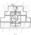
Figs. 1 to 3 illustrate a first embodiment according to the present disclosure; -
Fig. 4 shows a second embodiment according to the present disclosure; -
Fig. 5 shows a third embodiment according to the present disclosure. - With reference to
Fig. 1 to Fig. 5 , specific embodiments of the present disclosure will be described in detail below.. - According to an embodiment of the present disclosure, as shown in
Fig. 1 to Fig. 3 , there is provided a manual dual-power transfer switch, which includes a four-bar linkage, a firstmovable contact 1, a secondmovable contact 2, afirst power terminal 4 electrically connected with a first power supply (not shown), asecond power terminal 5 electrically connected with a second power supply (not shown), and a first loadstationary contact 6 accommodated in aswitch housing 3. - The movement of the four-bar linkage mechanism acts on the first
movable contact 1 and the secondmovable contact 2 at the same time, so that the manual dual-power transfer switch has the following states: - a state in which the first power supply is closed (as shown in
Fig. 1 ), in which only the firstmovable contact 1 is connected between the firstpower supply terminal 4 and the first loadstationary contact 6; or - a state in which the second power supply is closed (as shown in
Fig. 3 ), in which only the secondmovable contact 2 is connected between the secondpower supply terminal 5 and the second loadstationary contact 7; or - a dual-open state (as shown in
Fig. 2 ), in which the firstmovable contact 1 is not connected between thefirst power terminal 4 and the first loadstatic contact 6 and - the second
movable contact 2 is not connected between thesecond power terminal 5 and the second loadstatic contact 7. - According to the above embodiment of the present disclosure, the four-bar linkage includes a
switch handle 8, acam 9 and a connectingrod 10 connected between theswitch handle 8 and thecam 9. - According to the above embodiment of the present disclosure, the
switch handle 8 can be pivotally mounted on theswitch housing 3 around the handle axis 8-1. - The
cam 9 rotates around a cam axis 9-1. - One end of the connecting
rod 10 is eccentrically connected to the switch handle 8 relative to the handle axis 8-1. - The other end of the connecting
rod 10 is eccentrically connected to thecam 9 relative to the cam axis 9-1. - Rotation of the switch handle 8 drives rotation of the
cam 9 through the connectingrod 10. - According to the above embodiment of the present disclosure, the manual dual power transfer switch further includes a
first spring 11 and asecond spring 12. - One end of the
first spring 11 acts on theswitch housing 3. - The other end of the
first spring 11 acts on the firstmovable contact 1 and applies a force to close the firstmovable contact 1. - One end of the
second spring 12 acts on theswitch housing 3. - The other end of the
second spring 12 acts on the secondmovable contact 2 and applies a force to close the secondmovable contact 2. - According to the above embodiment of the present disclosure, the first
movable contact 1 is pivotally connected to thefirst power terminal 4. - The second
movable contact 2 is pivotally connected to thesecond power terminal 5. - According to a second embodiment of the present disclosure (as shown in
Fig. 4 ), the firstmovable contact 1 is pivotally connected to the first loadstationary contact 6. - The second
movable contact 2 is pivotally connected to the second loadstationary contact 7. - In this embodiment, the first
power supply terminal 4 and the secondpower supply terminal 5 are both electrified, while the first loadstatic contact 6 and the second loadstatic contact 7 are not electrified, making the switch handle 8 to be in a relatively safe state when the manual dual-power transfer switch is in the dual-open state and in the sate in which the first power supply is open. - According to a third embodiment of the present disclosure (as shown in
Fig. 5 ), in the state in which the first power supply is not closed, either end of the firstmovable contact 1 is not in contact with the firstpower supply terminal 4 or the first loadstationary contact 6. - In the state in which the second power supply is closed (as shown in
Fig. 5 ), both ends of the secondmovable contact 2 are in contact with the secondpower supply terminal 5 and the second loadstationary contact 7 at the same time. - In the state in which the first power supply is closed (not shown in
Fig. 5 ), both ends of the firstmovable contact 1 are in contact with the firstpower supply terminal 4 and the first loadstationary contact 6 at the same time. - In the state in which the second power supply is not closed (not shown in
Fig. 5 ), either end of the secondmovable contact 2 is not in contact with the secondpower supply terminal 5 or the second loadstationary contact 7. - According to the above embodiment of the present disclosure, the first
movable contact 1 has a first movable contact mating portion 1-1. - The second
movable contact 2 has a second movable contact mating portion 2-1. - The first movable contact mating portion 1-1 and the second movable contact mating portion 2-1 keep contact with an outer contour of the
cam 9. - According to the above embodiment of the present disclosure, the outer contour of the
cam 9 has, for example but not limited to, a first cam mating portion 9-2 and a second cam mating portion 9-3 which are in form of recesses. - The outer contour of the
cam 9 also has a portion of a first radius of curvature 9-4 and a portion of a second radius of curvature 9-5. - The second radius of curvature is larger than the first radius of curvature.
- Next, the operation of the manual dual-power transfer switch according to the present disclosure will be described in detail with reference to
Figs. 1 to 3 . When the switch handle 8 is in its first position (as shown infig. 1 ), through the connectingrod 10, the first movable contact mating portion 1-1 keeps in contact with the portion of the first radius of curvature 9-4 of thecam 9, while the second movable contact mating portion 2-1 keeps in contact with the portion of the second radius of curvature 9-5 of thecam 9; at this time, the firstmovable contact 1 is connected between thefirst power terminal 4 and the first loadstationary contact 6. - As shown in
Fig. 2 , when the switch handle 8 is turned manually to be in the dual-open state, thecam 9 is driven to rotate through the connectingrod 10, and the first movable contact mating portion 1-1 keeps in contact with the first cam mating portion 9-2 (for example, in a recess) while the second movable contact mating portion 2-1 keeps in contact with the second cam mating portion 9-3 (for example, in a recess). At this time, the firstmovable contact 1 is not connected between thefirst power terminal 4 and the first loadstatic contact 6 and the secondmovable contact 2 is not connected between thesecond power terminal 5 and the second loadstatic contact 7. - The radius of curvature of the first cam mating portion 9-2 and the radius of curvature of the second cam mating portion 9-3 are substantially equal to the second radius of curvature of the portion of the second radius of curvature 9-5.
- As shown in
Fig. 3 , when the switch handle 8 is turned manually to be in the second position, thecam 9 is driven to rotate through the connectingrod 10, and the first movable contact mating portion 1-1 keeps in contact with the portion of the second radius of curvature 9-5 of thecam 9, while the second movable contact mating portion 2-1 keeps in contact with the portion of the first radius of curvature 9-4 of the cam. - Through the above detailed description of the operation of the first embodiment of the manual dual-power transfer switch according to the present disclosure in conjunction with
Figs. 1 to 3 , those skilled in the art can know that the embodiments inFigs. 4 to 5 can realize the operation with the same effect. - With reference to specific embodiments, although the present disclosure has been described in the specification and drawings, it should be understood that various changes can be made by those skilled in the art without departing from the scope of the disclosure as defined in the claims, and various equivalents can be substituted for various elements therein. Furthermore, the combination and collocation of technical features, elements and/or functions among specific embodiments in this paper are clear, so according to these disclosures, those skilled in the art can appreciate that the technical features, elements and/or functions of an embodiment can be combined into another specific embodiment as appropriate, unless otherwise described above. In addition, according to the teaching of this disclosure, many changes can be made to adapt to special situations or materials without departing from the scope of the essence of this disclosure. Therefore, the present disclosure is not limited to the specific embodiments illustrated in the drawings and the specific embodiments described in the specification as the best mode presently contemplated for carrying out the present disclosure, but the present disclosure is intended to include all embodiments falling within the scope of the above description and the appended claims.
Claims (10)
- A manual dual power supply transfer switch, characterized in that:the manual dual-power transfer switch comprises a four-bar linkage, a first movable contact, a second movable contact, a first power terminal electrically connected with the first power supply, a second power terminal electrically connected with the second power supply, a first load static,wherein the movement of the four-bar linkage acts on the first movable contact and the second movable contact at the same time, so that the manual dual-power transfer switch has the following states:a state in which the first power supply is closed, wherein only the first movable contact is connected between the first power supply terminal and the first load stationary contact; ora state in which the second power supply is closed, wherein only the second movable contact is connected between the second power supply terminal and the second load stationary contact; ora dual-open state in which the first movable contact is not connected between the first power terminal and the first load static contact and the second movable contact is not connected between the second power terminal and the second load static contact.
- The manual dual-power transfer switch according to claim 1, wherein:
the four-bar linkage comprises a switch handle, a cam and a connecting rod connected between the switch handle and the cam. - The manual dual-power transfer switch according to claim 2, wherein:the switch handle is pivotally mounted on a switch housing around a handle axis;the cam rotates around a cam axis;one end of the connecting rod is eccentrically connected to the switch handle relative to the handle axis;the other end of the connecting rod is eccentrically connected to the cam relative to the cam axis; androtation of the switch handle drives rotation of the cam through the connecting rod.
- The manual dual-power transfer switch according to claim 3, wherein:the manual dual-power transfer switch further comprises a first spring and a second spring;one end of the first spring acts on the switch housing;the other end of the first spring acts on the first movable contact;one end of the second spring acts on the switch housing; andthe other end of the second spring acts on the second movable contact.
- The manual dual-power transfer switch according to claim 4, wherein:the first movable contact is pivotally connected to the first power terminal; andthe second movable contact is pivotally connected to the second power terminal.
- The manual dual-power transfer switch according to claim 4, wherein:the first movable contact is pivotally connected to the first load stationary contact; andthe second movable contact is pivotally connected to the second load stationary contact.
- The manual dual-power transfer switch according to claim 4, wherein:in a state in which the first power supply is not closed, either end of the first movable contact is not in contact with the first power supply terminal or the first load static contact;in the state in which the first power supply is closed, both ends of the first movable contact are in contact with the first power supply terminal and the first load static contact at the same time;in a state in which the second power supply is not closed, either end of the second movable contact is not in contact with the second power supply terminal or the second load static contact;in the state in which the second power supply is closed, both ends of the second movable contact are in contact with the second power supply terminal and the second load stationary contact at the same time.
- The manual dual-power transfer switch according to claim 4, wherein:the first movable contact is provided with a first movable contact mating portion;the second movable contact is provided with a second movable contact mating portion; andthe first movable contact mating portion and the second movable contact mating portion keep contact with the outer contour of the cam.
- The manual dual-power transfer switch according to claim 8, wherein:the outer contour of the cam has a first cam mating portion and a second cam mating portion;the outer contour of the cam also has a portion of a first radius of curvature and a portion of a second radius of curvature; andthe second radius of curvature is larger than the first radius of curvature.
- The manual dual-power transfer switch according to claim 9, wherein:when the switch handle is in its first position, the first movable contact mating portion keeps contact with the portion of the first radius of curvature radius the cam and the second movable contact mating portion keeps contact with the portion of the second radius of curvature radius of the cam through the connecting rod, and at this time the first movable contact is connected between the first power supply terminal and the first load static contact;when the switch handle is in its second position, the first movable contact mating portion keeps contact with the portion of the second radius of curvature of the cam and the second movable contact mating portion keeps contact with the portion of the first radius of curvature of the cam through the connecting rod, and at this time the second movable contact is connected between the second power terminal and the second load static contact; andwhen the switch handle is in the dual-open position, the first movable contact mating portion keeps in contact with the first cam mating portion and the second movable contact mating portion keeps in contact with the second cam mating portion through the connecting rod, and at this time, the first movable contact is not connected between the first power supply terminal and the first load static contact and the second movable contact is not connected between the second power supply terminal and the second load static contact.
Applications Claiming Priority (1)
| Application Number | Priority Date | Filing Date | Title |
|---|---|---|---|
| CN202020842986.8U CN211858444U (en) | 2020-05-19 | 2020-05-19 | Manual dual-power transfer switch |
Publications (2)
| Publication Number | Publication Date |
|---|---|
| EP3913650A1 true EP3913650A1 (en) | 2021-11-24 |
| EP3913650B1 EP3913650B1 (en) | 2024-04-10 |
Family
ID=73235672
Family Applications (1)
| Application Number | Title | Priority Date | Filing Date |
|---|---|---|---|
| EP21305620.3A Active EP3913650B1 (en) | 2020-05-19 | 2021-05-12 | Manual dual-power transfer switch |
Country Status (3)
| Country | Link |
|---|---|
| EP (1) | EP3913650B1 (en) |
| CN (1) | CN211858444U (en) |
| RU (1) | RU206456U1 (en) |
Cited By (2)
| Publication number | Priority date | Publication date | Assignee | Title |
|---|---|---|---|---|
| CN114784952A (en) * | 2022-05-27 | 2022-07-22 | 衢州杭氧气体有限公司 | Uninterruptible power supply system |
| CN116403842A (en) * | 2021-12-28 | 2023-07-07 | 上海良信电器股份有限公司 | An operating device for a dual power supply automatic transfer switch |
Citations (3)
| Publication number | Priority date | Publication date | Assignee | Title |
|---|---|---|---|---|
| EP2963665A1 (en) * | 2014-06-30 | 2016-01-06 | Siemens Aktiengesellschaft | Switching device and linkage mechanism thereof |
| WO2017136103A1 (en) * | 2016-02-04 | 2017-08-10 | Cooper Technologies Company | Fusible switch disconnect device for dc electrical power system |
| CN207925334U (en) * | 2018-01-09 | 2018-09-28 | 施耐德电器工业公司 | Dual-power transfer switch |
Family Cites Families (4)
| Publication number | Priority date | Publication date | Assignee | Title |
|---|---|---|---|---|
| DE740227C (en) * | 1934-06-23 | 1943-10-14 | Siemens App Und Maschinen G M | Alignment drive for a coarsely and finely adjustable weapon in a rotatable dome |
| RU2094282C1 (en) * | 1994-12-05 | 1997-10-27 | Новгородский государственный университет | Trailer-train coupling gear |
| RU2392130C2 (en) * | 2008-03-21 | 2010-06-20 | Евгений Борисович Пашуков | Method and device for spatial motion |
| GB2510119B (en) * | 2013-01-23 | 2015-03-04 | Horne Engineering Ltd | Valve arrangement, apparatus and methods of operation thereof |
-
2020
- 2020-05-19 CN CN202020842986.8U patent/CN211858444U/en active Active
-
2021
- 2021-05-12 EP EP21305620.3A patent/EP3913650B1/en active Active
- 2021-05-18 RU RU2021114003U patent/RU206456U1/en active
Patent Citations (3)
| Publication number | Priority date | Publication date | Assignee | Title |
|---|---|---|---|---|
| EP2963665A1 (en) * | 2014-06-30 | 2016-01-06 | Siemens Aktiengesellschaft | Switching device and linkage mechanism thereof |
| WO2017136103A1 (en) * | 2016-02-04 | 2017-08-10 | Cooper Technologies Company | Fusible switch disconnect device for dc electrical power system |
| CN207925334U (en) * | 2018-01-09 | 2018-09-28 | 施耐德电器工业公司 | Dual-power transfer switch |
Cited By (3)
| Publication number | Priority date | Publication date | Assignee | Title |
|---|---|---|---|---|
| CN116403842A (en) * | 2021-12-28 | 2023-07-07 | 上海良信电器股份有限公司 | An operating device for a dual power supply automatic transfer switch |
| CN114784952A (en) * | 2022-05-27 | 2022-07-22 | 衢州杭氧气体有限公司 | Uninterruptible power supply system |
| CN114784952B (en) * | 2022-05-27 | 2024-05-14 | 衢州杭氧气体有限公司 | Uninterruptible power supply system |
Also Published As
| Publication number | Publication date |
|---|---|
| RU206456U1 (en) | 2021-09-13 |
| EP3913650B1 (en) | 2024-04-10 |
| CN211858444U (en) | 2020-11-03 |
Similar Documents
| Publication | Publication Date | Title |
|---|---|---|
| EP3913650B1 (en) | Manual dual-power transfer switch | |
| CN112992620B (en) | Circuit breaker operating mechanism | |
| CN217061795U (en) | Operating mechanism and switch device | |
| CN209729805U (en) | A kind of double-energy storage operating mechanism of disconnecting switch | |
| CN217333977U (en) | Operating mechanism and switch device | |
| CN216749634U (en) | Operating mechanism of switch device and switch device | |
| JP2024537949A (en) | Switchgear operating mechanism and switchgear | |
| CN203456944U (en) | Double-power switch | |
| CN115148557B (en) | A switch operating system | |
| CN206602082U (en) | Miniature circuit breaker and circuit protection device | |
| CN219534315U (en) | Switching mechanism and isolating switch | |
| CN209843545U (en) | Transfer switch device | |
| CN220672458U (en) | Novel isolating switch | |
| CN101315837B (en) | Contact device for an electrical appliance and auxiliary signalling comprising such a device | |
| CN115602502A (en) | Circuit breaker tripping structure | |
| CN102496495A (en) | Energy storage spring operating mechanism for low-voltage disconnecting switch | |
| CN212392175U (en) | Operating device and circuit breaker of circuit breaker | |
| CN217280579U (en) | Integrated combined switch equipment | |
| CN220984365U (en) | Automatic transfer switch electric appliance and contact system thereof | |
| CN222813466U (en) | Transmission mechanism and isolating switch | |
| CN219498727U (en) | Handcart type solid insulation switch cabinet grounding knife device | |
| CN222530298U (en) | A switch cabinet anti-leakage grounding device | |
| CN219832498U (en) | Isolating switch | |
| KR20240116363A (en) | Operating mechanisms and switching devices | |
| CN222507509U (en) | Contact mechanism |
Legal Events
| Date | Code | Title | Description |
|---|---|---|---|
| PUAI | Public reference made under article 153(3) epc to a published international application that has entered the european phase |
Free format text: ORIGINAL CODE: 0009012 |
|
| STAA | Information on the status of an ep patent application or granted ep patent |
Free format text: STATUS: THE APPLICATION HAS BEEN PUBLISHED |
|
| AK | Designated contracting states |
Kind code of ref document: A1 Designated state(s): AL AT BE BG CH CY CZ DE DK EE ES FI FR GB GR HR HU IE IS IT LI LT LU LV MC MK MT NL NO PL PT RO RS SE SI SK SM TR |
|
| B565 | Issuance of search results under rule 164(2) epc |
Effective date: 20211013 |
|
| STAA | Information on the status of an ep patent application or granted ep patent |
Free format text: STATUS: REQUEST FOR EXAMINATION WAS MADE |
|
| 17P | Request for examination filed |
Effective date: 20220524 |
|
| RBV | Designated contracting states (corrected) |
Designated state(s): AL AT BE BG CH CY CZ DE DK EE ES FI FR GB GR HR HU IE IS IT LI LT LU LV MC MK MT NL NO PL PT RO RS SE SI SK SM TR |
|
| P01 | Opt-out of the competence of the unified patent court (upc) registered |
Effective date: 20230519 |
|
| GRAP | Despatch of communication of intention to grant a patent |
Free format text: ORIGINAL CODE: EPIDOSNIGR1 |
|
| STAA | Information on the status of an ep patent application or granted ep patent |
Free format text: STATUS: GRANT OF PATENT IS INTENDED |
|
| INTG | Intention to grant announced |
Effective date: 20231109 |
|
| GRAS | Grant fee paid |
Free format text: ORIGINAL CODE: EPIDOSNIGR3 |
|
| GRAA | (expected) grant |
Free format text: ORIGINAL CODE: 0009210 |
|
| STAA | Information on the status of an ep patent application or granted ep patent |
Free format text: STATUS: THE PATENT HAS BEEN GRANTED |
|
| AK | Designated contracting states |
Kind code of ref document: B1 Designated state(s): AL AT BE BG CH CY CZ DE DK EE ES FI FR GB GR HR HU IE IS IT LI LT LU LV MC MK MT NL NO PL PT RO RS SE SI SK SM TR |
|
| REG | Reference to a national code |
Ref country code: GB Ref legal event code: FG4D |
|
| REG | Reference to a national code |
Ref country code: CH Ref legal event code: EP |
|
| REG | Reference to a national code |
Ref country code: DE Ref legal event code: R096 Ref document number: 602021011602 Country of ref document: DE |
|
| REG | Reference to a national code |
Ref country code: IE Ref legal event code: FG4D |
|
| REG | Reference to a national code |
Ref country code: LT Ref legal event code: MG9D |
|
| REG | Reference to a national code |
Ref country code: NL Ref legal event code: MP Effective date: 20240410 |
|
| REG | Reference to a national code |
Ref country code: AT Ref legal event code: MK05 Ref document number: 1675797 Country of ref document: AT Kind code of ref document: T Effective date: 20240410 |
|
| PG25 | Lapsed in a contracting state [announced via postgrant information from national office to epo] |
Ref country code: NL Free format text: LAPSE BECAUSE OF FAILURE TO SUBMIT A TRANSLATION OF THE DESCRIPTION OR TO PAY THE FEE WITHIN THE PRESCRIBED TIME-LIMIT Effective date: 20240410 |
|
| PG25 | Lapsed in a contracting state [announced via postgrant information from national office to epo] |
Ref country code: NL Free format text: LAPSE BECAUSE OF FAILURE TO SUBMIT A TRANSLATION OF THE DESCRIPTION OR TO PAY THE FEE WITHIN THE PRESCRIBED TIME-LIMIT Effective date: 20240410 |
|
| PG25 | Lapsed in a contracting state [announced via postgrant information from national office to epo] |
Ref country code: IS Free format text: LAPSE BECAUSE OF FAILURE TO SUBMIT A TRANSLATION OF THE DESCRIPTION OR TO PAY THE FEE WITHIN THE PRESCRIBED TIME-LIMIT Effective date: 20240810 |
|
| PG25 | Lapsed in a contracting state [announced via postgrant information from national office to epo] |
Ref country code: BG Free format text: LAPSE BECAUSE OF FAILURE TO SUBMIT A TRANSLATION OF THE DESCRIPTION OR TO PAY THE FEE WITHIN THE PRESCRIBED TIME-LIMIT Effective date: 20240410 |
|
| PG25 | Lapsed in a contracting state [announced via postgrant information from national office to epo] |
Ref country code: HR Free format text: LAPSE BECAUSE OF FAILURE TO SUBMIT A TRANSLATION OF THE DESCRIPTION OR TO PAY THE FEE WITHIN THE PRESCRIBED TIME-LIMIT Effective date: 20240410 Ref country code: FI Free format text: LAPSE BECAUSE OF FAILURE TO SUBMIT A TRANSLATION OF THE DESCRIPTION OR TO PAY THE FEE WITHIN THE PRESCRIBED TIME-LIMIT Effective date: 20240410 |
|
| PG25 | Lapsed in a contracting state [announced via postgrant information from national office to epo] |
Ref country code: GR Free format text: LAPSE BECAUSE OF FAILURE TO SUBMIT A TRANSLATION OF THE DESCRIPTION OR TO PAY THE FEE WITHIN THE PRESCRIBED TIME-LIMIT Effective date: 20240711 |
|
| PG25 | Lapsed in a contracting state [announced via postgrant information from national office to epo] |
Ref country code: PT Free format text: LAPSE BECAUSE OF FAILURE TO SUBMIT A TRANSLATION OF THE DESCRIPTION OR TO PAY THE FEE WITHIN THE PRESCRIBED TIME-LIMIT Effective date: 20240812 |
|
| PG25 | Lapsed in a contracting state [announced via postgrant information from national office to epo] |
Ref country code: ES Free format text: LAPSE BECAUSE OF FAILURE TO SUBMIT A TRANSLATION OF THE DESCRIPTION OR TO PAY THE FEE WITHIN THE PRESCRIBED TIME-LIMIT Effective date: 20240410 |
|
| PG25 | Lapsed in a contracting state [announced via postgrant information from national office to epo] |
Ref country code: AT Free format text: LAPSE BECAUSE OF FAILURE TO SUBMIT A TRANSLATION OF THE DESCRIPTION OR TO PAY THE FEE WITHIN THE PRESCRIBED TIME-LIMIT Effective date: 20240410 |
|
| PG25 | Lapsed in a contracting state [announced via postgrant information from national office to epo] |
Ref country code: PL Free format text: LAPSE BECAUSE OF FAILURE TO SUBMIT A TRANSLATION OF THE DESCRIPTION OR TO PAY THE FEE WITHIN THE PRESCRIBED TIME-LIMIT Effective date: 20240410 |
|
| PG25 | Lapsed in a contracting state [announced via postgrant information from national office to epo] |
Ref country code: LV Free format text: LAPSE BECAUSE OF FAILURE TO SUBMIT A TRANSLATION OF THE DESCRIPTION OR TO PAY THE FEE WITHIN THE PRESCRIBED TIME-LIMIT Effective date: 20240410 |
|
| PG25 | Lapsed in a contracting state [announced via postgrant information from national office to epo] |
Ref country code: PT Free format text: LAPSE BECAUSE OF FAILURE TO SUBMIT A TRANSLATION OF THE DESCRIPTION OR TO PAY THE FEE WITHIN THE PRESCRIBED TIME-LIMIT Effective date: 20240812 Ref country code: PL Free format text: LAPSE BECAUSE OF FAILURE TO SUBMIT A TRANSLATION OF THE DESCRIPTION OR TO PAY THE FEE WITHIN THE PRESCRIBED TIME-LIMIT Effective date: 20240410 Ref country code: NO Free format text: LAPSE BECAUSE OF FAILURE TO SUBMIT A TRANSLATION OF THE DESCRIPTION OR TO PAY THE FEE WITHIN THE PRESCRIBED TIME-LIMIT Effective date: 20240710 Ref country code: LV Free format text: LAPSE BECAUSE OF FAILURE TO SUBMIT A TRANSLATION OF THE DESCRIPTION OR TO PAY THE FEE WITHIN THE PRESCRIBED TIME-LIMIT Effective date: 20240410 Ref country code: IS Free format text: LAPSE BECAUSE OF FAILURE TO SUBMIT A TRANSLATION OF THE DESCRIPTION OR TO PAY THE FEE WITHIN THE PRESCRIBED TIME-LIMIT Effective date: 20240810 Ref country code: HR Free format text: LAPSE BECAUSE OF FAILURE TO SUBMIT A TRANSLATION OF THE DESCRIPTION OR TO PAY THE FEE WITHIN THE PRESCRIBED TIME-LIMIT Effective date: 20240410 Ref country code: GR Free format text: LAPSE BECAUSE OF FAILURE TO SUBMIT A TRANSLATION OF THE DESCRIPTION OR TO PAY THE FEE WITHIN THE PRESCRIBED TIME-LIMIT Effective date: 20240711 Ref country code: FI Free format text: LAPSE BECAUSE OF FAILURE TO SUBMIT A TRANSLATION OF THE DESCRIPTION OR TO PAY THE FEE WITHIN THE PRESCRIBED TIME-LIMIT Effective date: 20240410 Ref country code: ES Free format text: LAPSE BECAUSE OF FAILURE TO SUBMIT A TRANSLATION OF THE DESCRIPTION OR TO PAY THE FEE WITHIN THE PRESCRIBED TIME-LIMIT Effective date: 20240410 Ref country code: BG Free format text: LAPSE BECAUSE OF FAILURE TO SUBMIT A TRANSLATION OF THE DESCRIPTION OR TO PAY THE FEE WITHIN THE PRESCRIBED TIME-LIMIT Effective date: 20240410 Ref country code: AT Free format text: LAPSE BECAUSE OF FAILURE TO SUBMIT A TRANSLATION OF THE DESCRIPTION OR TO PAY THE FEE WITHIN THE PRESCRIBED TIME-LIMIT Effective date: 20240410 Ref country code: RS Free format text: LAPSE BECAUSE OF FAILURE TO SUBMIT A TRANSLATION OF THE DESCRIPTION OR TO PAY THE FEE WITHIN THE PRESCRIBED TIME-LIMIT Effective date: 20240710 |
|
| REG | Reference to a national code |
Ref country code: DE Ref legal event code: R119 Ref document number: 602021011602 Country of ref document: DE |
|
| REG | Reference to a national code |
Ref country code: CH Ref legal event code: PL |
|
| PG25 | Lapsed in a contracting state [announced via postgrant information from national office to epo] |
Ref country code: DK Free format text: LAPSE BECAUSE OF FAILURE TO SUBMIT A TRANSLATION OF THE DESCRIPTION OR TO PAY THE FEE WITHIN THE PRESCRIBED TIME-LIMIT Effective date: 20240410 |
|
| PG25 | Lapsed in a contracting state [announced via postgrant information from national office to epo] |
Ref country code: LU Free format text: LAPSE BECAUSE OF NON-PAYMENT OF DUE FEES Effective date: 20240512 |
|
| PG25 | Lapsed in a contracting state [announced via postgrant information from national office to epo] |
Ref country code: EE Free format text: LAPSE BECAUSE OF FAILURE TO SUBMIT A TRANSLATION OF THE DESCRIPTION OR TO PAY THE FEE WITHIN THE PRESCRIBED TIME-LIMIT Effective date: 20240410 |
|
| PG25 | Lapsed in a contracting state [announced via postgrant information from national office to epo] |
Ref country code: CZ Free format text: LAPSE BECAUSE OF FAILURE TO SUBMIT A TRANSLATION OF THE DESCRIPTION OR TO PAY THE FEE WITHIN THE PRESCRIBED TIME-LIMIT Effective date: 20240410 |
|
| PG25 | Lapsed in a contracting state [announced via postgrant information from national office to epo] |
Ref country code: SK Free format text: LAPSE BECAUSE OF FAILURE TO SUBMIT A TRANSLATION OF THE DESCRIPTION OR TO PAY THE FEE WITHIN THE PRESCRIBED TIME-LIMIT Effective date: 20240410 Ref country code: RO Free format text: LAPSE BECAUSE OF FAILURE TO SUBMIT A TRANSLATION OF THE DESCRIPTION OR TO PAY THE FEE WITHIN THE PRESCRIBED TIME-LIMIT Effective date: 20240410 |
|
| PG25 | Lapsed in a contracting state [announced via postgrant information from national office to epo] |
Ref country code: SM Free format text: LAPSE BECAUSE OF FAILURE TO SUBMIT A TRANSLATION OF THE DESCRIPTION OR TO PAY THE FEE WITHIN THE PRESCRIBED TIME-LIMIT Effective date: 20240410 |
|
| PG25 | Lapsed in a contracting state [announced via postgrant information from national office to epo] |
Ref country code: SM Free format text: LAPSE BECAUSE OF FAILURE TO SUBMIT A TRANSLATION OF THE DESCRIPTION OR TO PAY THE FEE WITHIN THE PRESCRIBED TIME-LIMIT Effective date: 20240410 Ref country code: SK Free format text: LAPSE BECAUSE OF FAILURE TO SUBMIT A TRANSLATION OF THE DESCRIPTION OR TO PAY THE FEE WITHIN THE PRESCRIBED TIME-LIMIT Effective date: 20240410 Ref country code: RO Free format text: LAPSE BECAUSE OF FAILURE TO SUBMIT A TRANSLATION OF THE DESCRIPTION OR TO PAY THE FEE WITHIN THE PRESCRIBED TIME-LIMIT Effective date: 20240410 Ref country code: LU Free format text: LAPSE BECAUSE OF NON-PAYMENT OF DUE FEES Effective date: 20240512 Ref country code: EE Free format text: LAPSE BECAUSE OF FAILURE TO SUBMIT A TRANSLATION OF THE DESCRIPTION OR TO PAY THE FEE WITHIN THE PRESCRIBED TIME-LIMIT Effective date: 20240410 Ref country code: DK Free format text: LAPSE BECAUSE OF FAILURE TO SUBMIT A TRANSLATION OF THE DESCRIPTION OR TO PAY THE FEE WITHIN THE PRESCRIBED TIME-LIMIT Effective date: 20240410 Ref country code: CZ Free format text: LAPSE BECAUSE OF FAILURE TO SUBMIT A TRANSLATION OF THE DESCRIPTION OR TO PAY THE FEE WITHIN THE PRESCRIBED TIME-LIMIT Effective date: 20240410 Ref country code: MC Free format text: LAPSE BECAUSE OF FAILURE TO SUBMIT A TRANSLATION OF THE DESCRIPTION OR TO PAY THE FEE WITHIN THE PRESCRIBED TIME-LIMIT Effective date: 20240410 Ref country code: CH Free format text: LAPSE BECAUSE OF NON-PAYMENT OF DUE FEES Effective date: 20240531 |
|
| PG25 | Lapsed in a contracting state [announced via postgrant information from national office to epo] |
Ref country code: IT Free format text: LAPSE BECAUSE OF FAILURE TO SUBMIT A TRANSLATION OF THE DESCRIPTION OR TO PAY THE FEE WITHIN THE PRESCRIBED TIME-LIMIT Effective date: 20240410 |
|
| PLBE | No opposition filed within time limit |
Free format text: ORIGINAL CODE: 0009261 |
|
| STAA | Information on the status of an ep patent application or granted ep patent |
Free format text: STATUS: NO OPPOSITION FILED WITHIN TIME LIMIT |
|
| REG | Reference to a national code |
Ref country code: BE Ref legal event code: MM Effective date: 20240531 |
|
| 26N | No opposition filed |
Effective date: 20250113 |
|
| PG25 | Lapsed in a contracting state [announced via postgrant information from national office to epo] |
Ref country code: DE Free format text: LAPSE BECAUSE OF NON-PAYMENT OF DUE FEES Effective date: 20241203 |
|
| PG25 | Lapsed in a contracting state [announced via postgrant information from national office to epo] |
Ref country code: IE Free format text: LAPSE BECAUSE OF NON-PAYMENT OF DUE FEES Effective date: 20240512 |
|
| PG25 | Lapsed in a contracting state [announced via postgrant information from national office to epo] |
Ref country code: SI Free format text: LAPSE BECAUSE OF FAILURE TO SUBMIT A TRANSLATION OF THE DESCRIPTION OR TO PAY THE FEE WITHIN THE PRESCRIBED TIME-LIMIT Effective date: 20240410 Ref country code: BE Free format text: LAPSE BECAUSE OF NON-PAYMENT OF DUE FEES Effective date: 20240531 |
|
| PGFP | Annual fee paid to national office [announced via postgrant information from national office to epo] |
Ref country code: FR Payment date: 20250526 Year of fee payment: 5 |
|
| PG25 | Lapsed in a contracting state [announced via postgrant information from national office to epo] |
Ref country code: CY Free format text: LAPSE BECAUSE OF FAILURE TO SUBMIT A TRANSLATION OF THE DESCRIPTION OR TO PAY THE FEE WITHIN THE PRESCRIBED TIME-LIMIT; INVALID AB INITIO Effective date: 20210512 |
|
| PG25 | Lapsed in a contracting state [announced via postgrant information from national office to epo] |
Ref country code: HU Free format text: LAPSE BECAUSE OF FAILURE TO SUBMIT A TRANSLATION OF THE DESCRIPTION OR TO PAY THE FEE WITHIN THE PRESCRIBED TIME-LIMIT; INVALID AB INITIO Effective date: 20210512 |
|
| PG25 | Lapsed in a contracting state [announced via postgrant information from national office to epo] |
Ref country code: SE Free format text: LAPSE BECAUSE OF FAILURE TO SUBMIT A TRANSLATION OF THE DESCRIPTION OR TO PAY THE FEE WITHIN THE PRESCRIBED TIME-LIMIT Effective date: 20240410 |
|
| GBPC | Gb: european patent ceased through non-payment of renewal fee |
Effective date: 20250512 |
|
| PG25 | Lapsed in a contracting state [announced via postgrant information from national office to epo] |
Ref country code: GB Free format text: LAPSE BECAUSE OF NON-PAYMENT OF DUE FEES Effective date: 20250512 |