EP3913573B1 - Method for image processing, image signal processor in a terminal device - Google Patents
Method for image processing, image signal processor in a terminal device Download PDFInfo
- Publication number
- EP3913573B1 EP3913573B1 EP20176101.2A EP20176101A EP3913573B1 EP 3913573 B1 EP3913573 B1 EP 3913573B1 EP 20176101 A EP20176101 A EP 20176101A EP 3913573 B1 EP3913573 B1 EP 3913573B1
- Authority
- EP
- European Patent Office
- Prior art keywords
- image
- layer
- tone
- intermediate layer
- mapping
- Prior art date
- Legal status (The legal status is an assumption and is not a legal conclusion. Google has not performed a legal analysis and makes no representation as to the accuracy of the status listed.)
- Active
Links
- 238000000034 method Methods 0.000 title claims description 42
- 238000012545 processing Methods 0.000 title claims description 7
- 238000013507 mapping Methods 0.000 claims description 65
- 230000002708 enhancing effect Effects 0.000 claims description 6
- 238000004458 analytical method Methods 0.000 description 4
- 238000012937 correction Methods 0.000 description 2
- 238000004891 communication Methods 0.000 description 1
- 230000000593 degrading effect Effects 0.000 description 1
- 230000006866 deterioration Effects 0.000 description 1
- 125000001475 halogen functional group Chemical group 0.000 description 1
- 238000010191 image analysis Methods 0.000 description 1
- 238000003384 imaging method Methods 0.000 description 1
- 230000003116 impacting effect Effects 0.000 description 1
- 238000003672 processing method Methods 0.000 description 1
- 238000005070 sampling Methods 0.000 description 1
- 238000009738 saturating Methods 0.000 description 1
- 230000009466 transformation Effects 0.000 description 1
Images


Classifications
-
- G06T5/90—
-
- G06T5/92—
-
- G—PHYSICS
- G06—COMPUTING; CALCULATING OR COUNTING
- G06T—IMAGE DATA PROCESSING OR GENERATION, IN GENERAL
- G06T11/00—2D [Two Dimensional] image generation
- G06T11/60—Editing figures and text; Combining figures or text
-
- G—PHYSICS
- G06—COMPUTING; CALCULATING OR COUNTING
- G06T—IMAGE DATA PROCESSING OR GENERATION, IN GENERAL
- G06T3/00—Geometric image transformation in the plane of the image
- G06T3/40—Scaling the whole image or part thereof
-
- G—PHYSICS
- G06—COMPUTING; CALCULATING OR COUNTING
- G06T—IMAGE DATA PROCESSING OR GENERATION, IN GENERAL
- G06T5/00—Image enhancement or restoration
- G06T5/20—Image enhancement or restoration by the use of local operators
-
- G—PHYSICS
- G06—COMPUTING; CALCULATING OR COUNTING
- G06T—IMAGE DATA PROCESSING OR GENERATION, IN GENERAL
- G06T5/00—Image enhancement or restoration
- G06T5/40—Image enhancement or restoration by the use of histogram techniques
-
- G—PHYSICS
- G06—COMPUTING; CALCULATING OR COUNTING
- G06T—IMAGE DATA PROCESSING OR GENERATION, IN GENERAL
- G06T5/00—Image enhancement or restoration
- G06T5/50—Image enhancement or restoration by the use of more than one image, e.g. averaging, subtraction
-
- G—PHYSICS
- G06—COMPUTING; CALCULATING OR COUNTING
- G06T—IMAGE DATA PROCESSING OR GENERATION, IN GENERAL
- G06T7/00—Image analysis
- G06T7/10—Segmentation; Edge detection
-
- G—PHYSICS
- G06—COMPUTING; CALCULATING OR COUNTING
- G06T—IMAGE DATA PROCESSING OR GENERATION, IN GENERAL
- G06T2207/00—Indexing scheme for image analysis or image enhancement
- G06T2207/20—Special algorithmic details
- G06T2207/20016—Hierarchical, coarse-to-fine, multiscale or multiresolution image processing; Pyramid transform
-
- G—PHYSICS
- G06—COMPUTING; CALCULATING OR COUNTING
- G06T—IMAGE DATA PROCESSING OR GENERATION, IN GENERAL
- G06T2207/00—Indexing scheme for image analysis or image enhancement
- G06T2207/20—Special algorithmic details
- G06T2207/20024—Filtering details
-
- G—PHYSICS
- G06—COMPUTING; CALCULATING OR COUNTING
- G06T—IMAGE DATA PROCESSING OR GENERATION, IN GENERAL
- G06T2207/00—Indexing scheme for image analysis or image enhancement
- G06T2207/20—Special algorithmic details
- G06T2207/20172—Image enhancement details
- G06T2207/20208—High dynamic range [HDR] image processing
Definitions
- the present invention relates to a method for image processing, in particular to a tone mapping process of an image, an image signal processor (ISP) to carry out the method and a terminal comprising such an ISP.
- ISP image signal processor
- Tone mapping is a process of mapping the image pixels representing relatively high dynamic range to a viewing environment, i.e. displaying media, with relatively lower dynamic range. While doing this, tone mapping process is responsible to provide images to be represented as close as possible to the real-world scene. Therein tone mapping is one of the crucial blocks of the image processing between capturing of the image data towards the final image presented to the viewer which is responsible for altering the image contrast and brightness in order to successfully transform/map the original high dynamic range of the real-world to an image being displayed on a lower dynamic range displays.
- the image data is deconstructed into a plurality of N levels or layers.
- the first level in a Gaussian-pyramid algorithm for example, is a Gaussian-filtered image of the initial image data with a reduced resolution.
- the second level is a Gaussian-filtered image of the first level with reduced resolution with respect to the first level and so on up to the top level.
- Other filters such as a Laplacian-filter, can be used instead of the Gaussian-filter for deconstructing the initial image data into the plurality of levels.
- the contrast of one or more levels is adapted accordingly and afterwards the levels are collapsed to form the final image with an enhanced dynamic range beginning with the top level.
- the scene is usually underexposed in order to avoid burning/saturating the highlights with the cost of underexposed dark shadow regions.
- the known mapping algorithms deliver unacceptable results of the final image with a loss of details and insufficient dynamic range.
- the method for image processing, in particular image tone-mapping algorithm in accordance to the present invention comprises the steps of:
- a tone-mapping operator is applied to at least one of the intermediate layers.
- the tone of at least one intermediate layer generated by the above-referenced steps of collapsing the N image pyramid layers is changed or manipulated.
- appearance of the final image can be tailored in an intuitive and user pleasing way in the final image by impacting the desired tones (bright, mid-tones or shadows) of the initial image data.
- shadow regions can be brightened up, dark objects in the relatively bright areas may remain untouched without producing artifact nor loss of contrast.
- the tone-mapping operator is applied to at least two or more intermediate layers and even more preferably to each of the intermediate layers.
- the tone-mapping is distributed over the intermediate layers in order to achieve the desired result.
- the tone-mapping can be distributed according to a control algorithm which may analyze the content of the image via image statistics such as histogram of the image or can perform AI-based image classification/analysis.
- a contrast manipulation is applied to at least one, preferably more than one and more preferably to each of the plurality of N image pyramid layers. Additionally or alternatively, a contrast manipulation is applied to at least one, preferably more than one and more preferably to each of the intermediate layers.
- a contrast manipulation is applied to at least one, preferably more than one and more preferably to each of the intermediate layers.
- the tone-mapping operator is applied locally to sub-areas of the respective intermediate layer.
- sub-areas of the image data are areas smaller than the area of the complete image.
- the tone-mapping operator is applied to more than one sub-area of one of the respective intermediate layer.
- the tone-mapping operator is applied globally to the complete respective intermediate layer.
- local or global tone-mapping is feasible in order to specifically control the result of the final image.
- local tone-mapping and global tone-mapping can be freely selected and applied to different intermediate layers.
- the contrast manipulation is applied locally to sub-areas of the image pyramid layer and/or intermediate layer.
- sub-areas of the image pyramid layer and/or intermediate layer are areas smaller than the area of the complete image pyramid layer and/or intermediate layer.
- the contrast manipulation is applied to more than one sub-area of the respective image pyramid layer and/or intermediate layer.
- the contrast manipulation is applied globally to the complete respective image pyramid layer and/or intermediate layer.
- local or global contrast manipulation is feasible in order to specifically control the result of the final image.
- local contrast manipulation and global contrast manipulation can be freely selected and applied to different intermediate layers and/or image pyramid layers preferably in addition to the above-mentioned brightness manipulation.
- tone-mapping operator is in addition applied to the final image. Additionally or alternatively, tone-mapping operator is applied to the initial image data.
- L k ( i,j ) being the image pyramid layer of the k-layer
- UPSCALE is a resolution adaption function between the k+1-layer and the k-layer
- IM G k ( i,j ) being the respective intermediate layer
- i, j describe the position of the respective pixel in the image.
- the image data is deconstructed into a Laplacian-Pyramid.
- different filters can be used for deconstructing the initial image data into a respective image pyramid.
- different filters can be used during deconstruction the initial image data combinedly.
- the tone-mapping operator is implemented as brightness manipulation.
- the applied tone-mapping operator and in particular the applied brightness manipulation is determined in dependence on one or more parameters of a scene content such as high/low contrast scene, portrait or landscape scene, indoor scene, light sources, moving objects and so on.
- a scene content such as high/low contrast scene, portrait or landscape scene, indoor scene, light sources, moving objects and so on.
- the tone-mapping operator or the brightness manipulation can specifically tailored to the demands of the user and/or the given circumstances in order to achieve the desired result of the final image.
- the applied tone-mapping operator and in particular the applied brightness manipulation is determined in dependence on one or more parameters of ambience properties, such as low/high dynamic range, low/high lux, total gain of the image sensor, noise of the image, histogram of brightness, and user preference.
- ambience properties such as low/high dynamic range, low/high lux, total gain of the image sensor, noise of the image, histogram of brightness, and user preference.
- the tone-mapping operator or the brightness manipulation can specifically tailored to the demands of the user and/or the given circumstances in order to achieve the desired result of the final image.
- the brightness manipulation is implemented as Look-up-Table (LUT).
- the Look-up-Table can be either predefined as functional relationship or can be generated in dependence on one or more of a scene content, ambience properties, total gain of the image sensor, noise of the image sensor, histogram of brightness, and user preferences.
- the Look-up-Table a fast way is provided in order to apply the brightness manipulation to the respective intermediate layer or the respective image pyramid layer.
- the total tone-mapping and in particular the total brightness manipulation between the initial image data in the final image is distributed between the tone-mapping to one or more intermediate layer.
- the total tone-mapping and in particular the total brightness manipulation can be distributed between at least two intermediate layers.
- the total tone-mapping and in particular the total brightness manipulation may be evenly distributed such that to each intermediate layer the same tone-mapping/brightness manipulation is applied.
- at least two tone-mappings or brightness manipulations are unequal and thus the total brightness manipulation is unevenly distributed to meet further demands and provide a higher degree of freedom to achieve the desired result of the final image.
- the distribution can be determined on the scene content, such as overall brightness of the initial image data.
- the brightness manipulation might be evenly distributed while for a dark image the brightness manipulation might be unevenly distributed among the different intermediate layers.
- the total tone-mapping can be distributed according to a control algorithm which may analyze the content of the image via image statistics such as histogram of the image or can perform AI-based image classification/analysis.
- image statistics such as histogram of the image or can perform AI-based image classification/analysis.
- the brightness manipulation having the capability to distribute the LUTs over the layers will enable capability no only to decide whether to modify bright, mid-tones, or shadows, but it will also enable to control those, and the locality of the aforementioned traits based on image analysis. For example, if image content analysis based decision suggest that small details in shadows should be suppressed, but bigger details enhanced, that will be possible with the proposed solution.
- ISP image signal processor
- a terminal device comprising an ISP configured to carry out the steps of the method as previously described and an image sensor connected to the ISP to acquire the image data and providing the image data to the ISP for further processing.
- Figure 1 shows an example of a Pyramid based tone-mapping process which might be implemented as Laplacian-Pyramid based tone-mapping process starting with an input image as initial image data preferably from an image sensor. This image data is deconstructed into an image pyramid with a plurality of N image pyramid layers.
- the number N may depend on the resolution of the input image or might be selected in dependence on other parameters, such as computational capacity or the like.
- the Laplacian image pyramid is collapsed starting with the top level, level by level down to the bottom level wherein during the process of collapsing a brightness manipulation is applied to intermediate levels generated during the collapsing process.
- a brightness manipulation is applied to intermediate levels generated during the collapsing process.
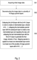
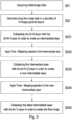
- Figure 2 shows a schematic representation of the method of the present invention with the first step S01 of acquiring initial image data preferably from an image sensor;
- L k ( i,j ) being the preferably the Laplacian image pyramid layer of the k-layer
- UPSCALE is a resolution adaption function between the k+1-layer and the k-layer
- i,j denote the pixel indices of the respective images.
- the tone-mapping operator can be applied only to one of the intermediate layers.
- the tone-mapping operator is applied to more than one intermediate layer and preferably to each of the intermediate layers.
- a tone-mapping operator is applied to the intermediate layer before collapse of an image pyramid layers with the previous intermediate layer.
- a first tone-mapping operator is applied to the intermediate layer.
- the tone-mapping operator might be implemented as a brightness manipulation.
- the brightness manipulation might be provided as one of a functional relationship, a Gamma-function (also known as Gamma-correction) or a contrast enhancing sigmoid function.
- the brightness manipulation is provided as Look-up-Table (LUT).
- LUT Look-up-Table
- the brightness manipulation can be provided by a brightness control which is configured to generate LUTs for each layer to be applied to individually.
- the brightness control might consider user preferences or manual controls of the application, tuning/configuration parameters as well as frame information such as lux, gain, exposure info, histograms etc. From this information together the brightness control generates the LUTs applied to the individual layers.
- the present invention is not limited to a specific LUT or brightness manipulation.
- the overall or total brightness manipulation applied to the image to achieve the desired result can be distributed among the different layers. This is shown in Figure 5 .
- the total brightness manipulation to be applied to the image is depicted as an example.
- Different LUTs can be implemented as described above. This total brightness manipulation is distributed among brightness manipulation of the one or more intermediate layers. Therein, the total brightness manipulation can be evenly distributed among the different layers. Alternatively, the total brightness manipulation can be applied differently to different intermediate layers. In this case the LUT for the different layers are different.
- Figure 6A shows and example of the method according to the present invention enhancing the shadow regions from left to right gradually using a brightness manipulation distributed among the intermediate layers applied during the image pyramid collapse. Therein, the contrast of the image is preserved and only the shadow regions are brightened up enhancing the dynamic range and providing a user pleasing representation of the real scene.
- Figure 6B shows enhancement of shadow regions from left to right gradually using a brightness manipulation applied only to the top layer of the Laplacian-Pyramid resulting in an uneven distribution of brightness and artifacts i.e. underexposed areas.
- Figure 6C shows an enhancement of the shadow regions from left to right gradually using brightness manipulation only to the final image after complete pyramid collapse, brighten up the image without enhancing the dynamic range of the image.
- Figure 7A shows a ratio image between the middle image (mid-bright) and the right image (brightest) of Figure 6A .
- the grey regions show the pixel with large differences compared to the original image with the dark pixels are marginally affected.
- Fig 7B shows a ratio image between the middle image (mid-bright) and the right image (brightest) of Figure 6B
- Fig 7C shows a ratio image between the middle image (mid-bright) and the right image (brightest) of Figure 6C .
- FIG. 7A the present invention overperforms the other alternatives shown in Figures 6B, 6C and 7B, 7C , respectively.
- Figures 6B, 6C and 7B, 7C As visible in Fig. 7B und 7C underexposed areas appear and a loss of contrast.
- Figures 8A, 8B and 8C showing the final image according to the method as described with respect to the Figures 6A, 6B and 6C , respectively.
- Figures 8A showing the result of the present invention having a high dynamic range without loss of contrast and evenly distributed brightness without loss of details or underexposed areas in the image.
- Figure 8B and Figure 8C suffer from dark halos or contrast deterioration while the method of the present invention shown in Figure 8A is able to manipulate brightness without producing artifacts nor loss of contrast.
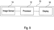
- a device 10 implementing the above described method.
- the above-mentioned method is implemented in a processor 12, such as an image signal processor (ISP), an application-specific integrated circuit (ASIC), and Field Programmable Gate Array (FPGA), a general-purpose processor or a graphical processor.
- the method can be hardware implemented or software implemented.
- the Processor 10 is connected to an image sensor 14.
- the image sensor 14 can be a CCD-sensor a camera or the like.
- initial image data can be acquired.
- This initial image data from the image sensor 14 is transmitted to the processor 12 to be processes according to the present invention.
- the processor is further connected to a display 16 to display the final image.
- the device 10 can be implemented by any kind of terminal, such as digital camera, smartphone, tablet, laptop or computer or the like. Further, although in Fig. 9 image sensor 14, processor 12, and display 16 are indicated to be implemented in one device 10, the individual modules can be implemented in more than one device. Thus, the image sensor 14 can be implemented for example in a smartphone for taking pictures. The initial image data acquired by the image sensor 14 then might be transmitted to a server or any other computational device by a communication connection. The server or other computational device may comprise the processor 12 to carry out the method according to the present invention. Then, the final image may be transmitted to a smartphone, tablet or any other device comprising a display 16 in order to display the final image.
- the final image from the server or other computational device may be transmitted to the same device that acquired the initial image data or another device.
- the final image might be stored preferably in a cloud storage or any other storage device and afterwards delivered on demand to the display device to display the final image.
Description
- The present invention relates to a method for image processing, in particular to a tone mapping process of an image, an image signal processor (ISP) to carry out the method and a terminal comprising such an ISP.
- Today's digital cameras and image sensors can only capture a limited range of the dynamic range that exists in real life. Furthermore, the viewing environment, such as a mobile device display, a computer display, TVs etc., for the captured image may support an even more narrow dynamic range than what the digital cameras and image sensors can capture.
- To mitigate this problem a tone mapping process is applied to the captured image data. Tone mapping is a process of mapping the image pixels representing relatively high dynamic range to a viewing environment, i.e. displaying media, with relatively lower dynamic range. While doing this, tone mapping process is responsible to provide images to be represented as close as possible to the real-world scene. Therein tone mapping is one of the crucial blocks of the image processing between capturing of the image data towards the final image presented to the viewer which is responsible for altering the image contrast and brightness in order to successfully transform/map the original high dynamic range of the real-world to an image being displayed on a lower dynamic range displays.
- Among other, pyramid-based tone mapping algorithms are well known to enhance the dynamic range of images and are described for example in
US 2004/101207 andUS 2010/142790 . Therefore, the image data is deconstructed into a plurality of N levels or layers. The first level, in a Gaussian-pyramid algorithm for example, is a Gaussian-filtered image of the initial image data with a reduced resolution. The second level is a Gaussian-filtered image of the first level with reduced resolution with respect to the first level and so on up to the top level. Other filters, such as a Laplacian-filter, can be used instead of the Gaussian-filter for deconstructing the initial image data into the plurality of levels. Subsequently, the contrast of one or more levels is adapted accordingly and afterwards the levels are collapsed to form the final image with an enhanced dynamic range beginning with the top level. However, due to the limited dynamic range of the digital imaging sensors and the image viewing media, i.e. displays, the scene is usually underexposed in order to avoid burning/saturating the highlights with the cost of underexposed dark shadow regions. Thus, the known mapping algorithms deliver unacceptable results of the final image with a loss of details and insufficient dynamic range. - It is an object of the present invention to provide an image processing method, in particular a tone-mapping method to improve the dynamic range of a final image.
- The above given problem is solved by the method for image processing of
claim 1, the image signal processor (ISP) ofclaim 14 and the terminal device of claim 15. - The method for image processing, in particular image tone-mapping algorithm in accordance to the present invention comprises the steps of:
- Acquiring initial image data, preferably from an image sensor;
- Deconstructing the image data in a plurality of N image pyramid layers;
- Collapsing the (k=N)-layer, i.e. the top layer, with the (k=N-1)-layer in order to create an intermediate layer, wherein k = N, ...,1;
- Collapsing the intermediate pyramid layer with the subsequent layer to create a new intermediate layer and repeating this step until collapsing the last intermediate layer with the first (k=1)-layer to generate the final image. Therein, the (k=N)-layer is also denoted as top layer and the (k=1)-layer is denoted as bottom layer. Collapsing starts with the top layer (k=N)-layer being collapsed with the subsequent (k=N-1)-layer. By collapsing these layers an intermediate layer is created. This intermediate layer is a starting point of the next collapsing step with the subsequent (k=N-2)-layer in order to create a new intermediate layer which is the starting layer of the next collapsing step and so on. This procedure is continued until the (k=1)-layer, i.e. the bottom layer, is reached. In this step the latest intermediate layer is collapsed with the bottom layer (k=1)-layer in order to generate the final image. Therein, N is an integer lager than 2.
- In accordance to the present invention a tone-mapping operator is applied to at least one of the intermediate layers. Thus, the tone of at least one intermediate layer generated by the above-referenced steps of collapsing the N image pyramid layers is changed or manipulated. By applying the tone-mapping operator to the intermediate layer, appearance of the final image can be tailored in an intuitive and user pleasing way in the final image by impacting the desired tones (bright, mid-tones or shadows) of the initial image data. Thus, by the tone-mapping operator of the present invention shadow regions can be brightened up, dark objects in the relatively bright areas may remain untouched without producing artifact nor loss of contrast.
- Preferably, the tone-mapping operator is applied to at least two or more intermediate layers and even more preferably to each of the intermediate layers. Thus, the tone-mapping is distributed over the intermediate layers in order to achieve the desired result. Therein, the tone-mapping can be distributed according to a control algorithm which may analyze the content of the image via image statistics such as histogram of the image or can perform AI-based image classification/analysis.
- Preferably, the tone-mapping operator is applied to the initial image data and/or to the final image for further adapting the appearance of the final image. Additionally or alternatively, the tone-mapping operator is applied to the top layer, i.e. the (k=N)-layer.
- Preferably, a contrast manipulation is applied to at least one, preferably more than one and more preferably to each of the plurality of N image pyramid layers. Additionally or alternatively, a contrast manipulation is applied to at least one, preferably more than one and more preferably to each of the intermediate layers. Thus, by applying a contrast manipulation to the at least one image pyramid layer or intermediate layer contrast of the final image can be manipulated and/or the dynamic range of the final image can be further enhanced.
- Preferably, the tone-mapping operator is applied locally to sub-areas of the respective intermediate layer. Therein, sub-areas of the image data are areas smaller than the area of the complete image. In particular, the tone-mapping operator is applied to more than one sub-area of one of the respective intermediate layer. Alternatively, the tone-mapping operator is applied globally to the complete respective intermediate layer. Thus, local or global tone-mapping is feasible in order to specifically control the result of the final image. Therein, it is possible to apply a local tone-mapping to one or more of the intermediate layers while a global tone-mapping is applied to at least one or more other intermediate layer. Thus, local tone-mapping and global tone-mapping can be freely selected and applied to different intermediate layers.
- Preferably, the contrast manipulation is applied locally to sub-areas of the image pyramid layer and/or intermediate layer. Therein, sub-areas of the image pyramid layer and/or intermediate layer are areas smaller than the area of the complete image pyramid layer and/or intermediate layer. In particular, the contrast manipulation is applied to more than one sub-area of the respective image pyramid layer and/or intermediate layer. Alternatively, the contrast manipulation is applied globally to the complete respective image pyramid layer and/or intermediate layer. Thus, local or global contrast manipulation is feasible in order to specifically control the result of the final image. Therein, it is possible to apply a local contrast manipulation to one or more of the intermediate layers and/or one or more of the image pyramid layers while a global contrast manipulation is applied to at least one or more other intermediate layer and/or image pyramid layer. Thus, local contrast manipulation and global contrast manipulation can be freely selected and applied to different intermediate layers and/or image pyramid layers preferably in addition to the above-mentioned brightness manipulation.
- Preferably, a tone-mapping operator is in addition applied to the final image. Additionally or alternatively, tone-mapping operator is applied to the initial image data.
- Preferably, a contrast manipulation is in addition applied to the final image. Additionally or alternatively, contrast manipulation is applied to the initial image data. Additionally or alternatively, contrast manipulation is applied to the top layer, i.e. the k=N-layer.
- Preferably, collapsing is performed by

with k = N - 1, ...,1 and
- Therein, Lk (i,j) being the image pyramid layer of the k-layer, UPSCALE is a resolution adaption function between the k+1-layer and the k-layer and IMGk (i,j) being the respective intermediate layer and IMGk=1 being the final image. Therein, i, j describe the position of the respective pixel in the image.
- Preferably, tone-mapping is applied by

- Preferably, the image data is deconstructed into a Laplacian-Pyramid. Therein, for a Laplacian-Pyramid preferably the k=1-layer is a Laplacian-filtered image with reduced resolution of the initial image data and the subsequent layers up to the top layer are Laplacian-filtered images of the respective previous layer with reduced resolution. Of course, different filters can be used for deconstructing the initial image data into a respective image pyramid. In particular, different filters can be used during deconstruction the initial image data combinedly.
- Preferably, image is deconstructed into a plurality of image pyramid layers, where the top layer, i.e. the (k=N)-layer in the pyramid is a low-resolution representation of the original image while the other layers beneath are carrying edge information. Some examples are Laplacian and Wavelet transformation based pyramids Preferably, the tone-mapping operator is implemented as brightness manipulation.
- Preferably, brightness manipulation is implemented as one of a functional relationship given by a predefined function such as a Gamma function, such as given by out = inGamma (also known as Gamma correction) or a contrast enhancing sigmoid function, for example given by

- Preferably, the applied tone-mapping operator and in particular the applied brightness manipulation is determined in dependence on one or more parameters of a scene content such as high/low contrast scene, portrait or landscape scene, indoor scene, light sources, moving objects and so on. Thus, the tone-mapping operator or the brightness manipulation can specifically tailored to the demands of the user and/or the given circumstances in order to achieve the desired result of the final image.
- Preferably, the applied tone-mapping operator and in particular the applied brightness manipulation is determined in dependence on one or more parameters of ambience properties, such as low/high dynamic range, low/high lux, total gain of the image sensor, noise of the image, histogram of brightness, and user preference. Thus, the tone-mapping operator or the brightness manipulation can specifically tailored to the demands of the user and/or the given circumstances in order to achieve the desired result of the final image.
- Preferably, the brightness manipulation is implemented as Look-up-Table (LUT). Therein, the Look-up-Table can be either predefined as functional relationship or can be generated in dependence on one or more of a scene content, ambience properties, total gain of the image sensor, noise of the image sensor, histogram of brightness, and user preferences. Thus, by the Look-up-Table a fast way is provided in order to apply the brightness manipulation to the respective intermediate layer or the respective image pyramid layer.
- Preferably, the total tone-mapping and in particular the total brightness manipulation between the initial image data in the final image is distributed between the tone-mapping to one or more intermediate layer. Thus, the total tone-mapping and in particular the total brightness manipulation can be distributed between at least two intermediate layers. Therein, in particular the total tone-mapping and in particular the total brightness manipulation may be evenly distributed such that to each intermediate layer the same tone-mapping/brightness manipulation is applied. Alternatively, at least two tone-mappings or brightness manipulations are unequal and thus the total brightness manipulation is unevenly distributed to meet further demands and provide a higher degree of freedom to achieve the desired result of the final image. Therein, the distribution can be determined on the scene content, such as overall brightness of the initial image data. Preferably, for a brighter image the brightness manipulation might be evenly distributed while for a dark image the brightness manipulation might be unevenly distributed among the different intermediate layers. Therein, the total tone-mapping can be distributed according to a control algorithm which may analyze the content of the image via image statistics such as histogram of the image or can perform AI-based image classification/analysis. Furthermore, for the brightness manipulation having the capability to distribute the LUTs over the layers will enable capability no only to decide whether to modify bright, mid-tones, or shadows, but it will also enable to control those, and the locality of the aforementioned traits based on image analysis. For example, if image content analysis based decision suggest that small details in shadows should be suppressed, but bigger details enhanced, that will be possible with the proposed solution.
- Further, it is an object of the present invention to provide an image signal processor (ISP) configured to carry out the steps of the method described above.
- Further, it is an object of the present invention to provide a terminal device comprising an ISP configured to carry out the steps of the method as previously described and an image sensor connected to the ISP to acquire the image data and providing the image data to the ISP for further processing.
- The invention is further described with reference to the accompanied figures. The figures show:
- Fig. 1
- an example of a Pyramid based tone-mapping process,
- Fig. 2
- a first embodiment according to the present invention,
- Fig. 3
- a second embodiment according to the present invention,
- Fig. 4
- determination of a Look-Up-Table according to the present invention,
- Fig. 5
- distribution of the brightness manipulation according to the present invention,
- Figs. 6A - 6C
- comparison of the results according to the present invention,
- Fig. 7
- detailed analysis of the comparison of
Figs. 6A to 6C , - Fig. 8A - 8C
- examples of the final image according to the present invention, and
- Fig. 9
- a device according to an embodiment of the present invention.
-
Figure 1 shows an example of a Pyramid based tone-mapping process which might be implemented as Laplacian-Pyramid based tone-mapping process starting with an input image as initial image data preferably from an image sensor. This image data is deconstructed into an image pyramid with a plurality of N image pyramid layers. - In the example given of
Figure 1 is N=4 wherein for the Laplacian-Pyramid based image pyramid a Laplacian-filter is applied to the initial image data of the input image for k=1, i.e. the bottom layer. Subsequently, a Laplacian-filter is applied to the bottom layer in combination with a down-sampling step to generate the next image pyramid layer k=2. This step is further carried out until the top level with k=N is reached. Therein, the number N may depend on the resolution of the input image or might be selected in dependence on other parameters, such as computational capacity or the like. Afterwards the Laplacian image pyramid is collapsed starting with the top level, level by level down to the bottom level wherein during the process of collapsing a brightness manipulation is applied to intermediate levels generated during the collapsing process. When all layers of the Laplacian image pyramid are collapsed the final image is generated comprising an improved dynamic range wherein shadow regions are brightened up, dark objects in the relatively bright area remain untouched without degrading of the contrast in the image. -
Figure 2 shows a schematic representation of the method of the present invention with the first step S01 of acquiring initial image data preferably from an image sensor; - in step S02 the initial image data is deconstructed into a plurality of N image pyramid layers; and
- in step S03 first the k=N layer is collapsed with the k=N-1 layer in order to create an intermediate layer. Subsequently, the intermediate layer is collapsed with the subsequent layer with k=N-2 to create a new intermediate layer and repeating this step for k=N, ...,1 until collapsing the last intermediate layer with the k=1 layer to generate the final image wherein a tone-mapping operator is applied to at least one intermediate layer.
- The collapse of the Laplacian-Pyramid is described by


- Therein, Lk (i,j) being the preferably the Laplacian image pyramid layer of the k-layer, UPSCALE is a resolution adaption function between the k+1-layer and the k-layer, IMG k with k=N, ...,1 being respective intermediate layer, wherein IMGk=1 being the final image. Further, i,j denote the pixel indices of the respective images.
- During the image pyramid collapse, after collapsing a certain level and generating the respective intermediate layer, tone-mapping of the intermediate level is applied before collapse with the next level is continued. This additional step is provided by

- Therein, the tone-mapping operator can be applied only to one of the intermediate layers. Preferably, the tone-mapping operator is applied to more than one intermediate layer and preferably to each of the intermediate layers. In this case, before collapse of an image pyramid layers with the previous intermediate layer a tone-mapping operator is applied to the intermediate layer. This situation is schematically depicted in
Figure 3 wherein in step S031 the (k=N)-layer is collapsed with the (k=N-1)-layer to create an intermediate layer. In step S032 a first tone-mapping operator is applied to the intermediate layer. Afterwards, the manipulated intermediate layer is collapsed with the (k=N-2)-layer in step S033 in order to create a new intermediate layer. In step S034 a further tone-mapping operator is applied to the new intermediate layer before collapsing the new intermediate layer with the next image layer. These steps are repeated until the bottom layer with k=1 is reached as final image. Thus, after each step of creating a new intermediate layer by collapsing the previous intermediate layer with the respective pyramid image layer a tone-mapping operator is applied to this intermediate layer. - Therein, the tone-mapping operator might be implemented as a brightness manipulation. The brightness manipulation might be provided as one of a functional relationship, a Gamma-function (also known as Gamma-correction) or a contrast enhancing sigmoid function.
- Preferably, the brightness manipulation is provided as Look-up-Table (LUT).
- As depicted in
Figure 4 the brightness manipulation can be provided by a brightness control which is configured to generate LUTs for each layer to be applied to individually. Therein, the brightness control might consider user preferences or manual controls of the application, tuning/configuration parameters as well as frame information such as lux, gain, exposure info, histograms etc. From this information together the brightness control generates the LUTs applied to the individual layers. However, the present invention is not limited to a specific LUT or brightness manipulation. - The overall or total brightness manipulation applied to the image to achieve the desired result can be distributed among the different layers. This is shown in
Figure 5 . In the top ofFigure 5 the total brightness manipulation to be applied to the image is depicted as an example. Different LUTs can be implemented as described above. This total brightness manipulation is distributed among brightness manipulation of the one or more intermediate layers. Therein, the total brightness manipulation can be evenly distributed among the different layers. Alternatively, the total brightness manipulation can be applied differently to different intermediate layers. In this case the LUT for the different layers are different. -
Figure 6A shows and example of the method according to the present invention enhancing the shadow regions from left to right gradually using a brightness manipulation distributed among the intermediate layers applied during the image pyramid collapse. Therein, the contrast of the image is preserved and only the shadow regions are brightened up enhancing the dynamic range and providing a user pleasing representation of the real scene. - As comparison,
Figure 6B shows enhancement of shadow regions from left to right gradually using a brightness manipulation applied only to the top layer of the Laplacian-Pyramid resulting in an uneven distribution of brightness and artifacts i.e. underexposed areas. Similarly, inFigure 6C shows an enhancement of the shadow regions from left to right gradually using brightness manipulation only to the final image after complete pyramid collapse, brighten up the image without enhancing the dynamic range of the image. -
Figure 7A shows a ratio image between the middle image (mid-bright) and the right image (brightest) ofFigure 6A . Therein the grey regions show the pixel with large differences compared to the original image with the dark pixels are marginally affected. Similar,Fig 7B shows a ratio image between the middle image (mid-bright) and the right image (brightest) ofFigure 6B andFig 7C shows a ratio image between the middle image (mid-bright) and the right image (brightest) ofFigure 6C . As can be seen from this comparison that with the method in accordance to the present invention by applying brightness manipulation to the intermediate layers during collapsing bright/shadow regions are well separated and thus, the brightness manipulation only influences dark regions while brighter regions are remain unchanged, preserving contrast. As shown inFig. 7A , the present invention overperforms the other alternatives shown inFigures 6B, 6C and7B, 7C , respectively. As visible inFig. underexposed areas appear and a loss of contrast.7B und 7CFigures 8A, 8B and 8C showing the final image according to the method as described with respect to theFigures 6A, 6B and 6C , respectively.Figures 8A showing the result of the present invention having a high dynamic range without loss of contrast and evenly distributed brightness without loss of details or underexposed areas in the image.Figure 8B and Figure 8C suffer from dark halos or contrast deterioration while the method of the present invention shown inFigure 8A is able to manipulate brightness without producing artifacts nor loss of contrast. - Referring now to
Fig 9 showing adevice 10 implementing the above described method. Preferably, the above-mentioned method is implemented in aprocessor 12, such as an image signal processor (ISP), an application-specific integrated circuit (ASIC), and Field Programmable Gate Array (FPGA), a general-purpose processor or a graphical processor. Further, the method can be hardware implemented or software implemented. Preferably, theProcessor 10 is connected to animage sensor 14. Theimage sensor 14 can be a CCD-sensor a camera or the like. By theimage sensor 14 initial image data can be acquired. This initial image data from theimage sensor 14 is transmitted to theprocessor 12 to be processes according to the present invention. Preferably, the processor is further connected to adisplay 16 to display the final image. - The
device 10 can be implemented by any kind of terminal, such as digital camera, smartphone, tablet, laptop or computer or the like. Further, although inFig. 9 image sensor 14,processor 12, anddisplay 16 are indicated to be implemented in onedevice 10, the individual modules can be implemented in more than one device. Thus, theimage sensor 14 can be implemented for example in a smartphone for taking pictures. The initial image data acquired by theimage sensor 14 then might be transmitted to a server or any other computational device by a communication connection. The server or other computational device may comprise theprocessor 12 to carry out the method according to the present invention. Then, the final image may be transmitted to a smartphone, tablet or any other device comprising adisplay 16 in order to display the final image. Therein, the final image from the server or other computational device may be transmitted to the same device that acquired the initial image data or another device. Preferably, the final image might be stored preferably in a cloud storage or any other storage device and afterwards delivered on demand to the display device to display the final image.
Claims (15)
- Method for image processing comprising the steps of acquiring (S01) initial image data, preferably from an image sensor;deconstructing (S02) the image data in a plurality of N image pyramid layers, wherein N>2;collapsing (S031) the N-layer with the (N-1)-layer in order to create an intermediate layer;collapsing (S033) the intermediate layer with the subsequent layer to create a new intermediate layer and repeating this step until collapsing the last intermediate layer with the first layer to generate the final image;wherein a tone-mapping operator is applied (S032, S034) to at least one intermediate layer.
- Method according to claim 1, characterized in that the tone-mapping operator is applied to each of the intermediate layers and/or each of the plurality of N image pyramid layers.
- Method according to claim 1 or 2, characterized in that the tone-mapping operator is applied locally to sub-areas of the respective intermediate layer and/or the respective image pyramid layer.
- Method according to claim 1 or 3, characterized in that tone-mapping operator is applied globally to the complete respective intermediate layer.
- Method according to any of claims 1 to 4, characterized in that a tone-mapping operator is applied to the final image and/or the image data and/or (k=N)-layer.
- Method according to any of claims 1 to 5, characterized in that collapsing is performed by


wherein Lk (i,j) being the image pyramid layer of the k-layer, UPSCALE a resolution adaption function between the (k+1)-layer and the k-layer, IMG k(i,j) being the respective intermediate layer and IMGk=1 being the final image. - Method according to claim 6, characterized in that the tone-mapping operator is applied according to


- Method according to any of claims 1 to 7, characterized that the image data is deconstructed into a Laplacian-Pyramid, wherein preferably the (k=1)-layer is a Laplacian-filtered image with reduced resolution of the image data and the subsequent layers are Laplacian-filtered images of the previous layer with reduced resolution.
- Method according to any of claims 1 to 8, characterized in that the tone-mapping operator is implemented as brightness manipulation.
- Method according to claim 9, characterized in that the brightness manipulation is implemented as one of a functional relationship, a Gamma-function, a contrast enhancing sigmoid function.
- Method according to claims 9 or 10, characterized in that the brightness manipulation is determined in dependence on one or more parameter of a scene content, ambience properties, total gain of the image sensor, noise of the image sensor, histogram of brightness and user preferences.
- Method according to any of claims 9 to 11, characterized in that the brightness manipulation is implemented as Look-Up-Table.
- Method according to any of claims 1 to 12, characterized in that a total tone-mapping between the image data and the final image is preferably evenly distributed between tone-mapping of more than one intermediate layer.
- Image signal processor (12), ISP, configured to carry out the steps of the method of any of claims 1 to 13.
- Terminal device comprising an ISP according to claim 14 and an image sensor (14) connected to the ISP (12) to acquire the image data and providing the image data to the ISP.
Priority Applications (4)
| Application Number | Priority Date | Filing Date | Title |
|---|---|---|---|
| EP20176101.2A EP3913573B1 (en) | 2020-05-22 | 2020-05-22 | Method for image processing, image signal processor in a terminal device |
| JP2021080483A JP7297010B2 (en) | 2020-05-22 | 2021-05-11 | Image processing method, image signal processor in terminal device |
| KR1020210061005A KR102477391B1 (en) | 2020-05-22 | 2021-05-11 | Method for image processing, image signal processor and termainal device |
| US17/319,073 US11625817B2 (en) | 2020-05-22 | 2021-05-12 | Pyramid-based tone mapping |
Applications Claiming Priority (1)
| Application Number | Priority Date | Filing Date | Title |
|---|---|---|---|
| EP20176101.2A EP3913573B1 (en) | 2020-05-22 | 2020-05-22 | Method for image processing, image signal processor in a terminal device |
Publications (2)
| Publication Number | Publication Date |
|---|---|
| EP3913573A1 EP3913573A1 (en) | 2021-11-24 |
| EP3913573B1 true EP3913573B1 (en) | 2023-11-08 |
Family
ID=70802778
Family Applications (1)
| Application Number | Title | Priority Date | Filing Date |
|---|---|---|---|
| EP20176101.2A Active EP3913573B1 (en) | 2020-05-22 | 2020-05-22 | Method for image processing, image signal processor in a terminal device |
Country Status (4)
| Country | Link |
|---|---|
| US (1) | US11625817B2 (en) |
| EP (1) | EP3913573B1 (en) |
| JP (1) | JP7297010B2 (en) |
| KR (1) | KR102477391B1 (en) |
Family Cites Families (10)
| Publication number | Priority date | Publication date | Assignee | Title |
|---|---|---|---|---|
| DE69214229T2 (en) * | 1991-08-14 | 1997-04-30 | Agfa Gevaert Nv | Method and device for improving the contrast of images |
| JP2001056856A (en) * | 1999-06-10 | 2001-02-27 | Fuji Photo Film Co Ltd | Method and device for image processing and recording medium |
| EP1223553A3 (en) * | 2000-10-17 | 2003-09-24 | Fuji Photo Film Co., Ltd. | Apparatus for suppressing noise by adapting filter characteristics to input image signal based on characteristics of input image signal |
| US7149358B2 (en) * | 2002-11-27 | 2006-12-12 | General Electric Company | Method and system for improving contrast using multi-resolution contrast based dynamic range management |
| EP1952344B1 (en) * | 2005-11-23 | 2011-06-08 | Cedara Software Corp. | Method and system for enhancing digital images |
| KR100925419B1 (en) * | 2006-12-19 | 2009-11-06 | 삼성전자주식회사 | Color Image Enhancement using Laplacian Pyramid and method thereof |
| US20100142790A1 (en) * | 2008-12-04 | 2010-06-10 | New Medical Co., Ltd. | Image processing method capable of enhancing contrast and reducing noise of digital image and image processing device using same |
| WO2011008239A1 (en) * | 2009-06-29 | 2011-01-20 | Thomson Licensing | Contrast enhancement |
| GB201410635D0 (en) * | 2014-06-13 | 2014-07-30 | Univ Bangor | Improvements in and relating to the display of images |
| CN113728624B (en) * | 2019-04-23 | 2023-11-14 | 杜比实验室特许公司 | Display management of high dynamic range images |
-
2020
- 2020-05-22 EP EP20176101.2A patent/EP3913573B1/en active Active
-
2021
- 2021-05-11 JP JP2021080483A patent/JP7297010B2/en active Active
- 2021-05-11 KR KR1020210061005A patent/KR102477391B1/en active IP Right Grant
- 2021-05-12 US US17/319,073 patent/US11625817B2/en active Active
Also Published As
| Publication number | Publication date |
|---|---|
| JP2021184249A (en) | 2021-12-02 |
| US20210366086A1 (en) | 2021-11-25 |
| JP7297010B2 (en) | 2023-06-23 |
| KR102477391B1 (en) | 2022-12-14 |
| KR20210145077A (en) | 2021-12-01 |
| EP3913573A1 (en) | 2021-11-24 |
| US11625817B2 (en) | 2023-04-11 |
Similar Documents
| Publication | Publication Date | Title |
|---|---|---|
| RU2433477C1 (en) | Image dynamic range expansion | |
| JP5012333B2 (en) | Image processing apparatus, image processing method, and imaging apparatus | |
| US9218653B2 (en) | Method and apparatus for dynamic range enhancement of an image | |
| JP5105209B2 (en) | Image processing apparatus and method, program, and recording medium | |
| EP1789922B1 (en) | Apparatus and method for processing images | |
| US6822762B2 (en) | Local color correction | |
| US8391598B2 (en) | Methods for performing local tone mapping | |
| US20070024721A1 (en) | Compensating for improperly exposed areas in digital images | |
| JP2008511048A (en) | Image processing method and computer software for image processing | |
| JP2017103569A (en) | Image processing device and image processing method | |
| US20210368088A1 (en) | Systems and methods of image enhancement | |
| JP2011100204A (en) | Image processor, image processing method, image processing program, imaging apparatus, and electronic device | |
| JP6243629B2 (en) | Image processing apparatus and method, and imaging apparatus | |
| CN113724144A (en) | Image processing method and image signal processor on terminal equipment | |
| EP3913573B1 (en) | Method for image processing, image signal processor in a terminal device | |
| JP6335614B2 (en) | Image processing apparatus, control method thereof, and program | |
| CN111462158A (en) | Image processing method and device, intelligent device and storage medium | |
| WO2016051716A1 (en) | Image processing method, image processing device, and recording medium for storing image processing program | |
| JP2010016479A (en) | Image processor, image processing method and imaging apparatus | |
| JP5267704B2 (en) | Image processing apparatus, image processing method, and imaging apparatus | |
| EP4068197A1 (en) | Method for image processing | |
| JP2006072660A (en) | Image processing device, image display device and electronic apparatus | |
| Pillman et al. | Image quality in consumer digital cameras | |
| CN116233332A (en) | Image processing apparatus, image processing method, generation method, and storage medium | |
| CN117897723A (en) | System and method for learning a tone curve for local image enhancement |
Legal Events
| Date | Code | Title | Description |
|---|---|---|---|
| PUAI | Public reference made under article 153(3) epc to a published international application that has entered the european phase |
Free format text: ORIGINAL CODE: 0009012 |
|
| STAA | Information on the status of an ep patent application or granted ep patent |
Free format text: STATUS: THE APPLICATION HAS BEEN PUBLISHED |
|
| AK | Designated contracting states |
Kind code of ref document: A1 Designated state(s): AL AT BE BG CH CY CZ DE DK EE ES FI FR GB GR HR HU IE IS IT LI LT LU LV MC MK MT NL NO PL PT RO RS SE SI SK SM TR |
|
| B565 | Issuance of search results under rule 164(2) epc |
Effective date: 20201022 |
|
| STAA | Information on the status of an ep patent application or granted ep patent |
Free format text: STATUS: REQUEST FOR EXAMINATION WAS MADE |
|
| 17P | Request for examination filed |
Effective date: 20211202 |
|
| RBV | Designated contracting states (corrected) |
Designated state(s): AL AT BE BG CH CY CZ DE DK EE ES FI FR GB GR HR HU IE IS IT LI LT LU LV MC MK MT NL NO PL PT RO RS SE SI SK SM TR |
|
| GRAP | Despatch of communication of intention to grant a patent |
Free format text: ORIGINAL CODE: EPIDOSNIGR1 |
|
| STAA | Information on the status of an ep patent application or granted ep patent |
Free format text: STATUS: GRANT OF PATENT IS INTENDED |
|
| INTG | Intention to grant announced |
Effective date: 20230622 |
|
| GRAS | Grant fee paid |
Free format text: ORIGINAL CODE: EPIDOSNIGR3 |
|
| GRAA | (expected) grant |
Free format text: ORIGINAL CODE: 0009210 |
|
| STAA | Information on the status of an ep patent application or granted ep patent |
Free format text: STATUS: THE PATENT HAS BEEN GRANTED |
|
| P01 | Opt-out of the competence of the unified patent court (upc) registered |
Effective date: 20230912 |
|
| AK | Designated contracting states |
Kind code of ref document: B1 Designated state(s): AL AT BE BG CH CY CZ DE DK EE ES FI FR GB GR HR HU IE IS IT LI LT LU LV MC MK MT NL NO PL PT RO RS SE SI SK SM TR |
|
| REG | Reference to a national code |
Ref country code: GB Ref legal event code: FG4D |
|
| REG | Reference to a national code |
Ref country code: CH Ref legal event code: EP |
|
| REG | Reference to a national code |
Ref country code: DE Ref legal event code: R096 Ref document number: 602020020572 Country of ref document: DE |
|
| REG | Reference to a national code |
Ref country code: IE Ref legal event code: FG4D |
|
| REG | Reference to a national code |
Ref country code: LT Ref legal event code: MG9D |
|
| REG | Reference to a national code |
Ref country code: NL Ref legal event code: MP Effective date: 20231108 |
|
| PG25 | Lapsed in a contracting state [announced via postgrant information from national office to epo] |
Ref country code: GR Free format text: LAPSE BECAUSE OF FAILURE TO SUBMIT A TRANSLATION OF THE DESCRIPTION OR TO PAY THE FEE WITHIN THE PRESCRIBED TIME-LIMIT Effective date: 20240209 |
|
| PG25 | Lapsed in a contracting state [announced via postgrant information from national office to epo] |
Ref country code: IS Free format text: LAPSE BECAUSE OF FAILURE TO SUBMIT A TRANSLATION OF THE DESCRIPTION OR TO PAY THE FEE WITHIN THE PRESCRIBED TIME-LIMIT Effective date: 20240308 |
|
| PG25 | Lapsed in a contracting state [announced via postgrant information from national office to epo] |
Ref country code: LT Free format text: LAPSE BECAUSE OF FAILURE TO SUBMIT A TRANSLATION OF THE DESCRIPTION OR TO PAY THE FEE WITHIN THE PRESCRIBED TIME-LIMIT Effective date: 20231108 |
|
| REG | Reference to a national code |
Ref country code: AT Ref legal event code: MK05 Ref document number: 1630317 Country of ref document: AT Kind code of ref document: T Effective date: 20231108 |
|
| PG25 | Lapsed in a contracting state [announced via postgrant information from national office to epo] |
Ref country code: NL Free format text: LAPSE BECAUSE OF FAILURE TO SUBMIT A TRANSLATION OF THE DESCRIPTION OR TO PAY THE FEE WITHIN THE PRESCRIBED TIME-LIMIT Effective date: 20231108 |