EP3913419A1 - Dispositif électronique de gestion d'affichage d'un écran d'affichage tête haute, système d'affichage, procédé de gestion et produit programme ordinateur associés - Google Patents
Dispositif électronique de gestion d'affichage d'un écran d'affichage tête haute, système d'affichage, procédé de gestion et produit programme ordinateur associés Download PDFInfo
- Publication number
- EP3913419A1 EP3913419A1 EP21174095.6A EP21174095A EP3913419A1 EP 3913419 A1 EP3913419 A1 EP 3913419A1 EP 21174095 A EP21174095 A EP 21174095A EP 3913419 A1 EP3913419 A1 EP 3913419A1
- Authority
- EP
- European Patent Office
- Prior art keywords
- display
- pilot
- aircraft
- alert
- plane
- Prior art date
- Legal status (The legal status is an assumption and is not a legal conclusion. Google has not performed a legal analysis and makes no representation as to the accuracy of the status listed.)
- Granted
Links
Images


Classifications
-
- G—PHYSICS
- G08—SIGNALLING
- G08G—TRAFFIC CONTROL SYSTEMS
- G08G5/00—Traffic control systems for aircraft
- G08G5/20—Arrangements for acquiring, generating, sharing or displaying traffic information
- G08G5/21—Arrangements for acquiring, generating, sharing or displaying traffic information located onboard the aircraft
-
- G—PHYSICS
- G02—OPTICS
- G02B—OPTICAL ELEMENTS, SYSTEMS OR APPARATUS
- G02B27/00—Optical systems or apparatus not provided for by any of the groups G02B1/00 - G02B26/00, G02B30/00
- G02B27/01—Head-up displays
- G02B27/017—Head mounted
- G02B27/0172—Head mounted characterised by optical features
-
- G—PHYSICS
- G02—OPTICS
- G02B—OPTICAL ELEMENTS, SYSTEMS OR APPARATUS
- G02B27/00—Optical systems or apparatus not provided for by any of the groups G02B1/00 - G02B26/00, G02B30/00
- G02B27/0093—Optical systems or apparatus not provided for by any of the groups G02B1/00 - G02B26/00, G02B30/00 with means for monitoring data relating to the user, e.g. head-tracking, eye-tracking
-
- G—PHYSICS
- G02—OPTICS
- G02B—OPTICAL ELEMENTS, SYSTEMS OR APPARATUS
- G02B27/00—Optical systems or apparatus not provided for by any of the groups G02B1/00 - G02B26/00, G02B30/00
- G02B27/01—Head-up displays
- G02B27/0101—Head-up displays characterised by optical features
-
- G—PHYSICS
- G02—OPTICS
- G02B—OPTICAL ELEMENTS, SYSTEMS OR APPARATUS
- G02B27/00—Optical systems or apparatus not provided for by any of the groups G02B1/00 - G02B26/00, G02B30/00
- G02B27/01—Head-up displays
- G02B27/0179—Display position adjusting means not related to the information to be displayed
-
- G—PHYSICS
- G06—COMPUTING OR CALCULATING; COUNTING
- G06F—ELECTRIC DIGITAL DATA PROCESSING
- G06F3/00—Input arrangements for transferring data to be processed into a form capable of being handled by the computer; Output arrangements for transferring data from processing unit to output unit, e.g. interface arrangements
- G06F3/01—Input arrangements or combined input and output arrangements for interaction between user and computer
- G06F3/011—Arrangements for interaction with the human body, e.g. for user immersion in virtual reality
- G06F3/013—Eye tracking input arrangements
-
- G—PHYSICS
- G08—SIGNALLING
- G08G—TRAFFIC CONTROL SYSTEMS
- G08G5/00—Traffic control systems for aircraft
- G08G5/50—Navigation or guidance aids
- G08G5/55—Navigation or guidance aids for a single aircraft
-
- G—PHYSICS
- G08—SIGNALLING
- G08G—TRAFFIC CONTROL SYSTEMS
- G08G5/00—Traffic control systems for aircraft
- G08G5/50—Navigation or guidance aids
- G08G5/58—Navigation or guidance aids for emergency situations, e.g. hijacking or bird strikes
-
- G—PHYSICS
- G02—OPTICS
- G02B—OPTICAL ELEMENTS, SYSTEMS OR APPARATUS
- G02B27/00—Optical systems or apparatus not provided for by any of the groups G02B1/00 - G02B26/00, G02B30/00
- G02B27/01—Head-up displays
- G02B27/0101—Head-up displays characterised by optical features
- G02B2027/0132—Head-up displays characterised by optical features comprising binocular systems
- G02B2027/0134—Head-up displays characterised by optical features comprising binocular systems of stereoscopic type
-
- G—PHYSICS
- G02—OPTICS
- G02B—OPTICAL ELEMENTS, SYSTEMS OR APPARATUS
- G02B27/00—Optical systems or apparatus not provided for by any of the groups G02B1/00 - G02B26/00, G02B30/00
- G02B27/01—Head-up displays
- G02B27/0101—Head-up displays characterised by optical features
- G02B2027/0141—Head-up displays characterised by optical features characterised by the informative content of the display
-
- G—PHYSICS
- G02—OPTICS
- G02B—OPTICAL ELEMENTS, SYSTEMS OR APPARATUS
- G02B27/00—Optical systems or apparatus not provided for by any of the groups G02B1/00 - G02B26/00, G02B30/00
- G02B27/01—Head-up displays
- G02B27/0179—Display position adjusting means not related to the information to be displayed
- G02B2027/0181—Adaptation to the pilot/driver
-
- G—PHYSICS
- G02—OPTICS
- G02B—OPTICAL ELEMENTS, SYSTEMS OR APPARATUS
- G02B27/00—Optical systems or apparatus not provided for by any of the groups G02B1/00 - G02B26/00, G02B30/00
- G02B27/01—Head-up displays
- G02B27/0179—Display position adjusting means not related to the information to be displayed
- G02B2027/0183—Adaptation to parameters characterising the motion of the vehicle
-
- G—PHYSICS
- G02—OPTICS
- G02B—OPTICAL ELEMENTS, SYSTEMS OR APPARATUS
- G02B27/00—Optical systems or apparatus not provided for by any of the groups G02B1/00 - G02B26/00, G02B30/00
- G02B27/01—Head-up displays
- G02B27/0179—Display position adjusting means not related to the information to be displayed
- G02B2027/0187—Display position adjusting means not related to the information to be displayed slaved to motion of at least a part of the body of the user, e.g. head, eye
-
- G—PHYSICS
- G02—OPTICS
- G02B—OPTICAL ELEMENTS, SYSTEMS OR APPARATUS
- G02B27/00—Optical systems or apparatus not provided for by any of the groups G02B1/00 - G02B26/00, G02B30/00
- G02B27/01—Head-up displays
- G02B2027/0192—Supplementary details
- G02B2027/0198—System for aligning or maintaining alignment of an image in a predetermined direction
Definitions
- the present invention relates to an electronic display management device for a head-up display system suitable for being on board an aircraft.
- the present invention also relates to a method for managing the display of a head-up display system suitable for being on board an aircraft.
- the present invention also relates to a computer program product comprising the software instructions which, when implemented by computer equipment, implement such a display management method.
- the invention relates more particularly to a helicopter, while being applicable to any type of aircraft, such as an airplane or a drone.
- the invention relates in particular to the field of the display of symbols, such as indicators, counters, targets, alerts, etc. on a so-called head-up display system, which thus makes it possible to project the symbols in front of the pilot of the aircraft via, for example, a head-up display screen.
- the display of symbols can be in compliant and / or non-compliant view. This thus results in cases of superposition of different symbols which make it difficult to read the information associated with these symbols which are superimposed, which may lead for the pilot to read ambiguities, and even in certain cases to miss an alert.
- the aim of the invention is thus to provide an electronic display management device allowing better readability of the symbols displayed and then offering better safety for the aircraft.
- the invention relates to an electronic display management device for a head-up display system suitable for being on board a control station of an aircraft that can be piloted by at least one pilot, the electronic device.
- display comprising a display module configured to display a plurality of symbols relating to the operation of the aircraft and to the environment of the aircraft via the head-up display system, in at least two distinct viewing planes, the planes of visualization each having a distinct depth along an axis of sight from the pilot, a determination module configured to determine a reference visualization plane corresponding to a plane of accommodation of the pilot's eyes, and an alert module configured to generate at least one alert to be displayed by the display module in the reference viewing plane.
- the symbols are displayed in at least two distinct viewing planes, by stereoscopy or by holography, which makes it possible to avoid the superimpositions of symbols and the ambiguity which could result therefrom.
- the determination and alert modules make it possible to determine the reference viewing plane corresponding to a plane of accommodation of the eyes of the pilot and to display an alert in this reference viewing plane, in order to ensure that the pilot sees the alert well and does not miss it.
- the device according to the invention thus makes it possible both to reduce the possible reading ambiguities between the symbols, thanks to the different viewing planes, while ensuring the pilot not to miss an alert which could occur in the event of display of an alert in a plan differ from the one to which it accommodates.
- the device according to the invention allows the pilot easier reading of the symbols while guaranteeing better reactivity to alerts, and therefore better safety for the flight of the aircraft.
- the subject of the invention is also a head-up display assembly comprising a head-up display system suitable for being placed in a control station of an aircraft, and an electronic display management device as defined below. above.
- the subject of the invention is also a computer program comprising software instructions which, when they are executed by a computer, implement a management method as defined above.
- the aircraft 10 is for example an airplane, a helicopter, or even a drone flying over terrain 12.
- the aircraft 10 is a flying machine that can be piloted by a pilot 14 via a control station 16, the control station 16 being arranged inside the aircraft 10 or else at a distance from the aircraft, in particular in the case of a drone.
- the control station 16 is here a cockpit of the aircraft 10. As can be seen on the figure 1 , the control station 16 comprises at least one seat 18 for the pilot 14, at least one head-up display assembly, advantageously at least one head-down display screen 22, a windshield 24 at least partially transparent and separating the interior of the cockpit of the external environment of the aircraft 10 and an orientation sensor 32.
- the head-up display assembly includes a head-up display system and an electronic display management device 34 for the head-up display system.
- the head-up display system is a head-up display screen 20.
- the head-up display system is a head-up holographic display device configured to represent at least one three-dimensional image in front of pilot 14 using interference from two laser beams, without a display screen. is not necessary.
- the head-up display screen 20 is at least partially transparent.
- the head-up display screen 20 is a visor 25 integrated into a helmet 26 suitable for being worn by the pilot 14, as visible on the figure 1 .
- the head-up display screen 20 is a transparent surface fixed in the cockpit and placed in front of the pilot 14.
- the head-up display screen 20 is the windshield 24.
- Head-down display screen 22 is a surface configured to display at least one image.
- the head-down display screen 22 is configured to display information relating to the aircraft 10, such as the speed, the altitude, the orientation of the aircraft 10 and / or information relating to the aircraft. environment outside the aircraft 10, such as air traffic information and weather conditions in the vicinity of the aircraft 10.
- the aircraft 10 is a drone that can be controlled remotely via a control station 16, for example on land, from which the drone is piloted.
- the control station 16 comprises here at least the seat 18 of the pilot 12 and the head-up display screen 20, advantageously at least one head-down display screen 22 and at least one environment display screen. , not shown.
- the environment display screen is configured to display the external environment of the aircraft 10 filmed from at least one camera on board by the drone.
- the orientation sensor 32 is able to determine an axis of sight AA 'of the gaze of the eyes 33 of the pilot 14. As visible on the picture. figure 1 , the sighting axis AA 'associated with a predetermined solid angle defines a field of view 35.
- the head-up display screen 20 is intended to be disposed at least partially in the field of view 35.
- the orientation sensor 32 is for example an accelerometer arranged in the helmet 26 of the pilot 14 and able to determine the posture of the head of the pilot 14 from the measured accelerations of the helmet 26.
- the orientation sensor 32 is thus specific to determining the sighting axis AA 'from the posture of the pilot's head 14 and from the orientation of the aircraft 10 received by the at least onboard sensor 17 in the aircraft 10.
- the orientation sensor 32 is an electromagnetic sensor suitable for determining the posture of the head of the pilot 14 from disturbances of a magnetic field due to the movement of the head of the pilot 14, according to a well-known technique of the pilot. skilled in the art.
- the electronic display management device 34 comprises a display module 36, a determination module 38 and an alert module 40.
- the display module 36 is configured to display a plurality of symbols 41, visible on the figure 2 , relating to the operation of the aircraft 10 and to the environment of the aircraft 10 on the head-up display screen 20.
- the symbols 41 are for example indicators relating to different systems of the aircraft 10, operational counters of the aircraft 10, such as a speed or altitude meter, buildings or vehicles of interest in the environment. of the aircraft 10, alerts etc.
- the symbols 41 advantageously comprise conforming symbols 42 and non-conforming symbols 43.
- conforming symbol 42 is meant a conforming symbol in at least one direction.
- the conformal symbol 42 is perfectly superimposed on the terrain actually seen by the pilot 14.
- the conformal symbol 42 is then typically fixed in the geo-terrestrial reference frame.
- the symbol conforms in only one or two directions of space.
- a symbol representing an attitude scale conforms only in the vertical direction, that is to say that said symbol remains vertical in the event of a roll movement of the head of the pilot 14, but moves according to the others. directions with the attitude movement of the pilot's head 14.
- non-compliant symbol 43 is meant a fixed symbol in the field of vision of the pilot 14.
- the display module 36 is configured to display the symbols 41 in at least two separate viewing planes 44A, 44B, 44C, 44D.
- the display module 36 is configured to display the symbols 41 in a number of display planes 44A, 44B, 44C, 44D between 2 and 4.
- the display module 36 is configured to display the symbols 41 stereoscopically.
- Stereoscopy is understood to mean a display technique making it possible to restore an impression of depth DA, DB, DC and DD and of relief to the pilot 14 thanks to the juxtaposition of two slightly different plane images, observed simultaneously and separately by each eye 33 of the pilot. pilot 14.
- each viewing plane 44A, 44B, 44C, 44D is associated with a respective depth DA, DB, DC and DD distinct along the sighting axis AA 'from the pilot 14.
- the eyes 33 of the pilot 14 accommodate in order to see clearly in an accommodation plane.
- accommodation is meant the focus of the vision of the pilot 14 by modifying the curvature of the lens according to the depth of an object, so as to form a clear and sharp image on the retina of the corresponding eye 33.
- the pilot 14 clearly sees only the symbols 41 displayed in said viewing plane 44A, 44B, 44C, 44D .
- the eyes 33 of the pilot 14 accommodate at the level of the second viewing plane 44B.
- the display module 36 is configured to display said symbols 41 in two different viewing planes 44.
- the two symbols 41 do not overlap and are easily differentiated by the pilot 14, by modifying the depth of the plane of accommodation of his eyes 33.
- the display module 36 is configured to display the conforming symbols 42 in the same viewing plane 44, advantageously in the deepest viewing plane 44D, in particular located at an infinite depth.
- the compliant symbols 42 are associated with the terrain 12 overflown by the aircraft 10.
- the terrain being seen almost infinitely by the pilot 14, the compliant symbols 42 then appear to be located in the same viewing plane 44D as the terrain. 12 for the pilot 14, thus facilitating the association of the conforming symbols 42 with the terrain 12.
- the compliant symbols 42 are displayed on a viewing plane 44 representative of their actual distance from the pilot 14.
- the display module 36 is further configured to display the symbols 41 associated with the same avionics function in the same respective viewing plane 44C, 44D.
- the avionics functions are for example the management of the speed of the aircraft 10, the management of the attitude of the aircraft 10, the management of the fuel of the aircraft 10, the mapping of the terrain 12, the management of the aircraft. orientation of the aircraft 10, communication management, etc.
- the pilot 14 has the symbols 41 associated with the same function in a single viewing plane 44C, 44D and can therefore easily view all the information associated with this function without having to change the respective viewing plane 44C, 44D.
- the ground speed and air speed counter of the aircraft 10 are displayed in the same display plane 44C.
- the display module 36 is further configured to display each symbol 41 with a light intensity of increasing value as a function of the depth D A , D B , D C and D D between the pilot 14 and the associated viewing plane 44 said symbol 41.
- the display module 36 compensates for this effect, and then allows the pilot 14 to view all the symbols 41 with the same ease.
- the determination module 38 is configured to determine, among the viewing planes 44A, 44B, 44C, 44D, a reference viewing plane 46 corresponding to the plane of accommodation of the eyes 33 of the pilot 14.
- the electronic display management device 34 further comprises a module 48 for monitoring the movement of the eyes of the pilot 14.
- the tracking module 48 is configured to calculate the plane of accommodation of the eyes 33 of the pilot 14 from the respective orientation of each eye 33 of the pilot 14.
- the tracking module 48 is in particular connected to a camera placed in the helmet 26 of the pilot 14 and filming the two eyes 33 of the pilot 14.
- the tracking module 48 is configured to receive and process the images filmed by said camera and determine the respective orientation of each eye 33. From these two orientations, the tracking module 48 is able to calculate the plane of accommodation of the eyes 33, and in particular the depth of the plane of accommodation.
- the determination module 38 is advantageously configured to detect the presence and / or the operating state of the tracking module 48.
- the determination module 38 is then configured to determine the reference viewing plane 46 from the accommodation plane calculated by the tracking module 48.
- the determination module 38 determines the reference viewing plane 46 by calculating the viewing plane 44B closest to the accommodation plane, in particular a possible viewing plane 44B coincident with the accommodation plane.
- the determination module 38 is configured to determine, as a reference viewing plane 46, successively each of the viewing planes 44A, 44B, 44C, 44D of a predefined set of viewing planes 44A, 44B, 44C, 44D.
- the determination module 38 determines the predefined set of display planes 44A, 44B, 44C, 44D for example by selecting only the display planes 44A, 44B, 44C, 44D corresponding to a current phase of flight of the aircraft 10.
- the flight phase of the aircraft 10 is, for example, a takeoff phase, a cruising phase, a tactical phase or a landing phase of the aircraft 10.
- the predefined set comprises the reference viewing plane 46 calculated from the accommodation plane calculated by the tracking module 48 and the viewing planes 44 directly adjacent to the reference viewing plane 46.
- the determination module 38 thus successively determines each of the viewing planes 44A, 44B, 44C, 44D of the predefined set as being the reference viewing plane 46, such that at least one of these viewing planes of reference 46 is the viewing plane 44B closest to the accommodation plane of the pilot 14.
- the alert module 40 is configured to generate an alert 49 to be displayed by the display module 36 in the reference viewing plane 46.
- the alert 49 is chosen from the group consisting of an alert on the ground height of the aircraft 10, an alert on the speed of the aircraft 10, an alert on a malfunction of the aircraft 10, an alert on the presence of an element of interest in the environment of the aircraft 10, an alert of location of a target outside the field of vision 35 of the pilot 14 and an alert of location of the sighting of the gaze of a co-pilot.
- the height alert corresponds for example to a passage of the aircraft 10 below a predetermined threshold height, in order to warn the pilot 14 of a risk to the safety of the aircraft 10.
- the speed alert corresponds for example to an exceeding by the aircraft 10 of a predetermined threshold speed beyond which the operation of the aircraft 10 can be degraded.
- a malfunction of the aircraft 10 corresponds for example to a failure or an error of an avionics system of the aircraft 10.
- the element of interest is for example another aircraft, an obstacle on the ground 12 located near the aircraft 10 or a place on which the aircraft is intended to land such as a hospital, an area of accident or an offshore platform.
- the target location alert outside the field of vision 35 is for example an arrow placed on the side of the viewing plane 44 indicating the direction in which said target is located.
- the location alert for the sighting of the co-pilot's gaze is for example a graphic representation of the line of sight of the co-pilot.
- the display module 36 is thus able to display the alert 49 in the reference viewing plane 46 corresponding to the viewing plane 44B closest to the accommodation plane of the pilot 14.
- the alert 49 is therefore displayed close to the accommodation plan of the pilot 14, which allows the pilot 14 to instantly see this alert 49 and to react accordingly, with a low probability that he does not see the alert. 49.
- the display module 36 is thus able to display the alert successively in the different reference viewing planes 46 from among the predefined set of viewing planes 44.
- the display module 36 is suitable for displaying the alert 49, for example at a frequency between 2 Hz and 3 Hz, on each successive reference viewing plane 46.
- the display module 36 is configured to display the alert 49 with a decreasing size as a function of the depth D A , D B , D C and D D between the pilot 14 and the viewing plane 44 in which the alert 49 is displayed.
- the display module 36 is able to display the alert 49 successively at predetermined depths, these depths corresponding or not to depths D A , D B , D C and D D of a plane of visualization 44.
- the display module 36 is suitable for displaying the alert 49 successively and iteratively at a depth of 5m, then a depth of 4.5m, then a depth of 4m, then a depth of 3.5m, etc.
- This scanning of the planes makes it possible to ensure that the alert 49 is displayed near the accommodation plane of the pilot 14. In addition, this scan makes it possible to obtain an impression of flashing of the alert 49 in the plane. accommodation of the pilot 14, which makes it possible to draw even more the attention of the pilot 14 to this alert 49.
- Adapting the display size of the alert 49 with the display depth of this alert 49 also makes it possible to draw the pilot 14's attention even more to this alert 49.
- the electronic display management device 34 comprises an information processing unit 50 formed for example by a memory 52 and a processor 54 associated with the memory 52.
- the display module 36, the determination module 38, the alert module 40, and as an optional addition the monitoring module 48 are each produced in the form of software, or a software brick, which can be executed by the processor 54.
- the memory 52 of the electronic management device d 'display 34 is then able to store head-up display software, software for determining the reference viewing plane 46, software for generating the alert and software for calculating the plane of accommodation of the eyes 33 of the pilot 14.
- the processor 54 is then able to execute each of this software.
- the display module 36, the determination module 38, the alert module 40 and, as an optional addition, the monitoring module 48 are each produced in the form of a programmable logic component, such as an FPGA (standing for Field Programmable Gate Array), or in the form of a dedicated integrated circuit, such as an ASIC (standing for Application Specific Integrated Circuit).
- a programmable logic component such as an FPGA (standing for Field Programmable Gate Array)
- ASIC Application Specific Integrated Circuit
- the electronic display management device 34 When the electronic display management device 34 is produced in the form of one or more software, that is to say in the form of a computer program, it is also able to be recorded on a medium, not shown, computer readable.
- the computer readable medium is, for example, a medium capable of memorizing electronic instructions and of being coupled to a bus of a computer system.
- the readable medium is an optical disc, a magneto-optical disc, a ROM memory, a RAM memory, any type of non-volatile memory (for example EPROM, EEPROM, FLASH, NVRAM), a magnetic card or an optical card.
- a computer program comprising software instructions is then stored on the readable medium.
- the aircraft 10 flies over the terrain 12.
- the method then comprises a first step 100 of display by the display module 36 of a plurality of symbols 41 in at least two distinct viewing planes 44.
- each symbol 41 is displayed with a light intensity of increasing value as a function of the depth D A , D B , D C and D D between the pilot 14 and the viewing plane 44A, 44B, 44C, 44D associated with said symbol 41 .
- the conforming symbols 42 are displayed in the same viewing plane 44, advantageously in the deepest viewing plane 44D.
- the method comprises an intermediate step 105 for detecting, by the determination module 38, the presence and / or the operating state of the monitoring module 48.
- the method comprises a step 110 of determining the reference viewing plane 46 corresponding to the plane of accommodation of the eyes of the pilot 14.
- the method then comprises a sub-step of calculating, by the tracking module 48, the plane of accommodation of the eyes of the pilot 14 from at least the respective orientation of each eye of the pilot 14.
- the reference viewing plane 46 is then determined by the determination module 38 from the accommodation plane thus calculated. In particular, the reference viewing plane 46 is determined by calculating the viewing plane 44B closest to the accommodation plane.
- the reference viewing plane 46 is determined by the determination module 38 as being successively each of the viewing planes 44A, 44B, 44C, 44D of a predefined set of viewing planes 44A, 44B, 44C , 44D.
- the method then comprises a step 120 of generation by the alert module 40 of an alert 49 to be displayed in the reference viewing plane 46.
- the alert 49 is displayed by the display module 36 in the reference viewing plane 46 corresponding to the viewing plane 44B closest to the plane of accommodation of the eyes 33 of the pilot 14.
- the alert 49 is therefore displayed near the plane of accommodation of the eyes 33 of the pilot 14, which allows the pilot 14 to instantly see this alert and to react appropriately, without the risk that he will not see the alert.
- the alert 49 is displayed by the display module 36 successively in the different reference viewing planes 46.
- This scanning of the reference viewing planes 46 makes it possible to ensure that the alert 49 is displayed near the plane of accommodation of the eyes 33 of the pilot 14 and gives an impression of flashing of the alert 49 in the plane. of accommodation of the eyes 33 of the pilot 14, which makes it possible to draw even more the attention of the pilot 14 to this alert 49.
- the display management device 34 thus makes it possible to reduce the possible reading ambiguities between the symbols 41 thanks to the different display planes 44A, 44B, 44C, 44D.
- the functional grouping of the symbols 41 with a respective viewing plane for each function such as an avionics function
- the display of symbols 42 conforming to infinity and the display with increasing light intensity as a function of the depth make it possible to further reduce the ambiguities in reading the symbols 41.
- the invention also allows the pilot 14 to limit the risk of a failure to perceive an alert 49 which could occur if this alert 49 is displayed in a plane that differs from the plane of accommodation of his eyes 33.
- the display management device 34 allows the alert 49 to be displayed near the plane of accommodation of the eyes 33 of the pilot 14 so that the latter visualizes the alert 49 more quickly.
- the invention allows the pilot 14 easier reading of the symbols 41, while guaranteeing better responsiveness to alerts 49, and therefore better safety for the flight of the aircraft 10 through safer piloting.
Landscapes
- Physics & Mathematics (AREA)
- General Physics & Mathematics (AREA)
- Engineering & Computer Science (AREA)
- Optics & Photonics (AREA)
- Aviation & Aerospace Engineering (AREA)
- General Engineering & Computer Science (AREA)
- Theoretical Computer Science (AREA)
- Human Computer Interaction (AREA)
- Business, Economics & Management (AREA)
- Emergency Management (AREA)
- Traffic Control Systems (AREA)
Abstract
Description
- La présente invention concerne un dispositif électronique de gestion d'affichage d'un système d'affichage tête haute propre à être embarqué dans un aéronef.
- La présente invention concerne également un procédé de gestion d'affichage d'un système d'affichage tête haute propre à être embarqué dans un aéronef.
- La présente invention concerne également un produit programme ordinateur comportant les instructions logicielles qui, lorsque mises en œuvre par un équipement informatique, mettent en œuvre un tel procédé de gestion d'affichage.
- L'invention concerne plus particulièrement un hélicoptère, tout en étant applicable à tout type d'aéronef, tel qu'un avion ou un drone.
- L'invention concerne en particulier le domaine de l'affichage de symboles, tels que des indicateurs, des compteurs, des cibles, des alertes, etc sur un système d'affichage, dit tête haute, qui permet ainsi de projeter les symboles devant le pilote de l'aéronef via par exemple un écran d'affichage tête haute.
- Il est connu d'afficher ces symboles dans un même plan de visualisation, projeté par exemple à l'infini. Les yeux du pilote accommodent alors afin de focaliser la vision du pilote à l'infini et voir ainsi les symboles de façon nette.
- L'affichage des symboles peut être en vue conforme et/ou non-conforme. Il en résulte ainsi des cas de superposition de différents symboles qui rendent difficiles la lecture des informations associées à ces symboles qui se superposent pouvant conduire pour le pilote à des ambiguïtés de lecture, et même dans certains cas à rater une alerte.
- Il existe donc un besoin d'obtenir un affichage permettant une lecture des symboles plus aisée pour le pilote, afin de réduire ces ambigüités et de limiter le risque de rater une alerte.
- Le but de l'invention est ainsi de proposer un dispositif électronique de gestion d'affichage permettant une meilleure facilité de lecture des symboles affichés et offrant alors une meilleure sécurité pour l'aéronef.
- A cet effet, l'invention a pour objet un dispositif électronique de gestion d'affichage d'un système d'affichage tête haute propre à être embarqué dans un poste de commande d'un aéronef pilotable par au moins un pilote, le dispositif électronique d'affichage comprenant un module d'affichage configuré pour afficher une pluralité de symboles relatifs au fonctionnement de l'aéronef et à l'environnement de l'aéronef via le système d'affichage tête haute, dans au moins deux plans de visualisation distincts, les plans de visualisation étant chacun de profondeur distincte selon un axe de visée à partir du pilote, un module de détermination configuré pour déterminer un plan de visualisation de référence correspondant à un plan d'accommodation des yeux du pilote, et un module d'alerte configuré pour générer au moins une alerte à afficher par le module d'affichage dans le plan de visualisation de référence.
- Ainsi, les symboles sont affichés dans au moins deux plans de visualisation distincts, par stéréoscopie ou par holographie, ce qui permet d'éviter les superpositions de symboles et l'ambigüité qui pourrait en découler. Les modules de détermination et d'alerte permettent de déterminer le plan de visualisation de référence correspondant à un plan d'accommodation des yeux du pilote et d'afficher une alerte dans ce plan de visualisation de référence, afin de s'assurer que le pilote voit bien l'alerte et ne la rate pas.
- Le dispositif selon l'invention permet ainsi à la fois de diminuer les ambiguïtés de lecture possibles entre les symboles, grâce aux différents plans de visualisation, tout en assurant au pilote de ne pas rater une alerte qui pourrait survenir en cas d'affichage d'une alerte dans un plan diffèrent de celui vers lequel il accommode.
- Ainsi le dispositif selon l'invention permet au pilote une lecture plus aisée des symboles tout en garantissant une meilleure réactivité aux alertes, et donc une meilleure sécurité pour le vol de l'aéronef.
- Suivant d'autres aspects avantageux de l'invention, le dispositif électronique de gestion comprend une ou plusieurs des caractéristiques suivantes, prises isolément ou suivant toutes les combinaisons techniquement possibles :
- le dispositif électronique comprend en outre un module de suivi du mouvement des yeux du pilote, le module de suivi étant configuré pour calculer le plan d'accommodation des yeux du pilote à partir de l'orientation respective de chaque œil du pilote, et le module de détermination étant configuré pour déterminer le plan de visualisation de référence à partir du plan d'accommodation calculé ;
- le module de détermination est configuré pour déterminer, en tant que plan de visualisation de référence, successivement chacun des plans de visualisation d'un ensemble prédéfini de plans de visualisation ;
- lorsque deux symboles sont alignés selon l'axe de visée, le module d'affichage est configuré pour afficher lesdits symboles dans deux plans de visualisation différents ;
- les symboles comprennent des symboles conformes et des symboles non-conformes, le module d'affichage étant configuré pour afficher les symboles conformes dans un même plan de visualisation, avantageusement dans le plan de visualisation le plus profond ;
- le module d'affichage est configuré pour afficher chaque symbole avec une intensité lumineuse de valeur croissante en fonction de la profondeur entre le pilote et le plan de visualisation associé audit symbole ; et
- l'alerte est choisie parmi le groupe constitué de : une alerte sur la hauteur au sol de l'aéronef ; une alerte sur la vitesse de l'aéronef ; une alerte sur un dysfonctionnement de l'aéronef ; une alerte sur la présence d'un élément d'intérêt dans l'environnement de l'aéronef ; une alerte de localisation d'une cible hors champ de vision du pilote ; et une alerte de localisation de la visée du regard d'un copilote.
- L'invention a également pour objet un ensemble d'affichage tête haute comprenant un système d'affichage tête haute propre à être disposé dans un poste de commande d'un aéronef, et un dispositif électronique de gestion d'affichage tel que défini ci-dessus.
- L'invention a également pour objet un procédé de gestion d'affichage d'un système d'affichage tête haute propre à être embarqué dans un poste de commande d'un aéronef pilotable par au moins un pilote, le procédé de gestion d'affichage comprenant au moins les étapes suivantes :
- affichage d'une pluralité de symboles relatifs au fonctionnement de l'aéronef et à l'environnement de l'aéronef via le système d'affichage tête haute, dans au moins deux plans de visualisation distincts, les plans de visualisation étant chacun de profondeur distincte selon un axe de visée à partir du pilote,
- détermination d'un plan de visualisation de référence correspondant à un plan d'accommodation des yeux du pilote, et
- génération d'au moins une alerte à afficher par le module d'affichage dans le plan de visualisation de référence.
- L'invention a également pour objet un programme d'ordinateur comportant des instructions logicielles qui, lorsqu'elles sont exécutées par un ordinateur, mettent en œuvre un procédé de gestion tel que défini ci-dessus.
- Ces caractéristiques et avantages de l'invention apparaîtront plus clairement à la lecture de la description qui va suivre, donnée uniquement à titre d'exemple non limitatif, et faite en référence aux dessins annexés, sur lesquels :
- [
Fig 1 ] lafigure 1 est une vue, schématique et de côté, d'un cockpit d'un aéronef ; - [
Fig 2 ] lafigure 2 est une représentation schématique en perspective d'un écran d'affichage tête haute ; - [
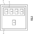
Fig 3 ] lafigure 3 est une représentation schématique d'un dispositif électronique de gestion d'affichage selon l'invention ; et - [
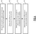
Fig 4 ] lafigure 4 est un organigramme d'un procédé, selon l'invention, de gestion d'affichage de l'écran d'affichage tête haute, le procédé étant mis en œuvre par le dispositif électronique de gestion d'affichage de lafigure 3 . - Dans ce qui suit, le terme « vertical » s'entend de manière générale par rapport à la direction de la force de gravité. Le terme « horizontal » s'entend de manière générale comme perpendiculaire à la direction verticale.
- Par la suite, l'invention est décrite en considérant un aéronef 10. Toutefois, l'homme du métier comprendra que l'invention est applicable à tout type de véhicule, tel qu'un aéronef, un véhicule automobile ou un véhicule ferroviaire.
- L'aéronef 10 est par exemple un avion, un hélicoptère, ou encore un drone survolant un terrain 12. Autrement dit, l'aéronef 10 est un engin volant pilotable par un pilote 14 via un poste de commande 16, le poste de commande 16 étant disposé à l'intérieur de l'aéronef 10 ou bien à distance de l'aéronef, notamment dans le cas d'un drone.
- Le poste de commande 16 est ici un cockpit de l'aéronef 10. Comme visible sur la
figure 1 , le poste de commande 16 comporte au moins un siège 18 pour le pilote 14, au moins un ensemble d'affichage tête haute, avantageusement au moins un écran d'affichage tête basse 22, un pare-brise 24 au moins partiellement transparent et séparant l'intérieur du cockpit de l'environnement extérieur de l'aéronef 10 et un capteur d'orientation 32. - L'ensemble d'affichage tête haute comprend un système d'affichage tête haute et un dispositif électronique 34 de gestion d'affichage du système d'affichage tête haute.
- Dans un mode de réalisation, le système d'affichage tête haute est un écran d'affichage tête haute 20.
- En variante, le système d'affichage tête haute est un dispositif de représentation holographique tête haute configuré pour représenter au moins une image en trois dimensions en face du pilote 14 en utilisant les interférences de deux faisceaux laser, sans qu'un écran d'affichage ne soit nécessaire.
- L'écran d'affichage tête haute 20 est au moins partiellement transparent. Avantageusement, l'écran d'affichage tête haute 20 est une visière 25 intégrée dans un casque 26 propre à être porté par le pilote 14, comme visible sur la
figure 1 . En variante, l'écran d'affichage tête haute 20 est une surface transparente fixée dans le cockpit et placée devant le pilote 14. En variante encore, l'écran d'affichage tête haute 20 est le pare-brise 24. - L'écran d'affichage tête basse 22 est une surface configurée pour afficher au moins une image. Avantageusement, l'écran d'affichage tête basse 22 est configuré pour afficher des informations relatives à l'aéronef 10, telles que la vitesse, l'altitude, l'orientation de l'aéronef 10 et/ou des informations relatives à l'environnement extérieur de l'aéronef 10, telles que des informations de trafic aérien et des conditions météorologiques aux environs de l'aéronef 10.
- Selon un autre mode de réalisation, non représenté, l'aéronef 10 est un drone pilotable à distance via un poste de commande 16, par exemple terrestre, à partir duquel le pilotage du drone est effectué. Le poste de commande 16 comporte ici au moins le siège 18 du pilote 12 et l'écran d'affichage tête haute 20, avantageusement l'au moins un écran d'affichage tête basse 22 et au moins un écran d'affichage d'environnement, non représenté. L'écran d'affichage d'environnement est configuré pour afficher l'environnement extérieur de l'aéronef 10 filmé à partir d'au moins une caméra embarquée par le drone.
- Le capteur d'orientation 32 est propre à déterminer un axe de visée A-A' du regard des yeux 33 du pilote 14. Comme visible sur la
figure 1 , l'axe de visée A-A' associé à un angle solide prédéterminé définit un champ de vue 35. - L'écran d'affichage tête haute 20 est destiné à être disposé au moins partiellement dans le champ de vue 35.
- Le capteur d'orientation 32 est par exemple un accéléromètre disposé dans le casque 26 du pilote 14 et propre à déterminer la posture de la tête du pilote 14 à partir des accélérations mesurées du casque 26. Le capteur d'orientation 32 est ainsi propre à déterminer l'axe de visée A-A' à partir de la posture de la tête du pilote 14 et de l'orientation de l'aéronef 10 reçue par l'au moins capteur embarqué 17 dans l'aéronef 10.
- En variante, le capteur d'orientation 32 est un capteur électromagnétique propre à déterminer la posture de la tête du pilote 14 à partir de perturbations d'un champ magnétique dues au mouvement de la tête du pilote 14, selon une technique bien connue de l'homme du métier.
- Comme visible sur la
figure 3 , le dispositif électronique de gestion d'affichage 34 comprend un module d'affichage 36, un module de détermination 38 et un module d'alerte 40. - Le module d'affichage 36 est configuré pour afficher une pluralité de symboles 41, visibles sur la
figure 2 , relatifs au fonctionnement de l'aéronef 10 et à l'environnement de l'aéronef 10 sur l'écran d'affichage tête haute 20. - Les symboles 41 sont par exemple des indicateurs concernant différents systèmes de l'aéronef 10, des compteurs opérationnels de l'aéronef 10, tels qu'un compteur de vitesse ou d'altitude, des bâtiments ou des véhicules d'intérêt dans l'environnement de l'aéronef 10, des alertes etc.
- Les symboles 41 comprennent avantageusement des symboles conformes 42 et des symboles non-conformes 43.
- On entend par symbole conforme 42 un symbole conforme selon au moins une direction. Lorsque le symbole est conforme selon les trois directions de l'espace, le symbole conforme 42 se superpose parfaitement au terrain effectivement vu par le pilote 14. Le symbole conforme 42 est alors typiquement fixe dans le référentiel géo-terrestre. En variante, le symbole est conforme selon uniquement une ou deux directions de l'espace. Par exemple, un symbole représentant une échelle d'attitude est conforme uniquement selon la direction verticale, c'est-à-dire que ledit symbole reste vertical en cas de mouvement de roulis de la tête du pilote 14, mais se déplace selon les autres directions avec le mouvement d'assiette de la tête du pilote 14.
- On entend par symbole non-conforme 43 un symbole fixe dans le champ de vision du pilote 14.
- En particulier, le module d'affichage 36 est configuré pour afficher les symboles 41 dans au moins deux plans de visualisation 44A, 44B, 44C, 44D distincts.
- Avantageusement, le module d'affichage 36 est configuré pour afficher les symboles 41 dans un nombre de plans de visualisations 44A, 44B, 44C, 44D compris entre 2 et 4.
- Lorsque le système d'affichage tête haute est un écran d'affichage tête haute 20, le module d'affichage 36 est configuré pour afficher les symboles 41 par stéréoscopie.
- On entend par stéréoscopie, une technique d'affichage permettant de restituer une impression de profondeur DA, DB, DC et DD et de relief au pilote 14 grâce à la juxtaposition de deux images planes légèrement différentes, observées simultanément et séparément par chaque œil 33 du pilote 14.
- Comme visible sur la
figure 2 , chaque plan de visualisation 44A, 44B, 44C, 44D est associé à une profondeur respective DA, DB, DC et DD distincte selon l'axe de visée A-A' à partir du pilote 14. - En particulier, les yeux 33 du pilote 14 accommodent afin de voir nettement dans un plan d'accommodation. On entend par accommodation, la mise au point de la vision du pilote 14 grâce à des modifications de courbure du cristallin selon la profondeur d'un objet, de façon à former une image claire et nette sur la rétine de l'œil 33 correspondant.
- Ainsi, lorsque le plan d'accommodation se confond avec l'un des plans de visualisation 44A, 44B, 44C, 44D, le pilote 14 voit de manière nette uniquement les symboles 41 affichés dans ledit plan de visualisation 44A, 44B, 44C, 44D.
- Par exemple, dans l'exemple de la
figure 2 , les yeux 33 du pilote 14 accommodent au niveau du deuxième plan de visualisation 44B. - Les symboles 41 ainsi affichés dans différents plans de visualisation 44A, 44B, 44C, 44D sont donc plus facilement visualisables par le pilote 14 sans ambigüité.
- En particulier, lorsque deux symboles 41 sont alignés selon l'axe de visée A-A' du pilote 14, le module d'affichage 36 est configuré pour afficher lesdits symboles 41 dans deux plans de visualisation 44 différents.
- Ainsi, les deux symboles 41 ne se superposent pas et sont différentiables facilement par le pilote 14, en modifiant la profondeur du plan d'accommodation de ses yeux 33.
- En complément, le module d'affichage 36 est configuré pour afficher les symboles conformes 42 dans un même plan de visualisation 44, avantageusement dans le plan de visualisation 44D le plus profond, notamment situé à une profondeur infinie.
- En particulier, les symboles conformes 42 sont associés au terrain 12 survolé par l'aéronef 10. Le terrain étant vu quasiment à l'infini par le pilote 14, les symboles conformes 42 semblent alors situés dans le même plan de visualisation 44D que le terrain 12 pour le pilote 14, facilitant ainsi l'association des symboles conformes 42 avec le terrain 12.
- En variante, les symboles conformes 42 sont affichés sur un plan de visualisation 44 représentatif de leur distance réelle par rapport au pilote 14.
- Le module d'affichage 36 est en outre configuré pour afficher les symboles 41 associés à une même fonction avionique dans un même plan de visualisation 44C, 44D respectif.
- Les fonctions avioniques sont par exemple la gestion de la vitesse de l'aéronef 10, la gestion de l'attitude de l'aéronef 10, la gestion du carburant de l'aéronef 10, la cartographie du terrain 12, la gestion de l'orientation de l'aéronef 10, la gestion de la communication, etc.
- Ainsi, le pilote 14 dispose des symboles 41 associés à une même fonction dans un unique plan de visualisation 44C, 44D et peut donc visualiser facilement l'ensemble des informations associés à cette fonction sans avoir à changer de plan de visualisation 44C, 44D respectif.
- A titre d'exemple, le compteur de vitesse sol et de vitesse air de l'aéronef 10 sont affichés dans un même plan de visualisation 44C.
- Le module de d'affichage 36 est en outre configuré pour afficher chaque symbole 41 avec une intensité lumineuse de valeur croissante en fonction de la profondeur DA, DB, DC et DD entre le pilote 14 et le plan de visualisation 44 associé audit symbole 41.
- En effet, plus un symbole 41 est affiché à une profondeur DA, DB, DC et DD importante, moins ce symbole 41 ressort en évidence pour le pilote 14. En affichant les symboles 41 avec une intensité lumineuse de valeur croissante en fonction de la profondeur DA, DB, DC et DD, le module d'affichage 36 compense cet effet, et permet alors au pilote 14 de visualiser tous les symboles 41 avec la même facilité.
- Le module de détermination 38 est configuré pour déterminer, parmi les plans de visualisation 44A, 44B, 44C, 44D, un plan de visualisation de référence 46 correspondant au plan d'accommodation des yeux 33 du pilote 14.
- En complément facultatif, le dispositif électronique de gestion d'affichage 34 comprend en outre un module 48 de suivi du mouvement des yeux du pilote 14.
- Le module de suivi 48 est configuré pour calculer le plan d'accommodation des yeux 33 du pilote 14 à partir de l'orientation respective de chaque œil 33 du pilote 14.
- Le module de suivi 48 est notamment relié à une caméra placée dans le casque 26 du pilote 14 et filmant les deux yeux 33 du pilote 14. Le module de suivi 48 est configuré pour recevoir et traiter les images filmées par ladite caméra et déterminer l'orientation respective de chaque œil 33. A partir de ces deux orientations, le module de suivi 48 est propre à calculer le plan d'accommodation des yeux 33, et en particulier la profondeur du plan d'accommodation.
- Le module de détermination 38 est avantageusement configuré pour détecter la présence et/ou l'état de marche du module de suivi 48.
- Le module de détermination 38 est alors configuré pour déterminer le plan de visualisation de référence 46 à partir du plan d'accommodation calculé par le module de suivi 48.
- En particulier, le module de détermination 38 détermine le plan de visualisation de référence 46 en calculant le plan de visualisation 44B le plus proche du plan d'accommodation, notamment un éventuel plan de visualisation 44B confondu avec le plan d'accommodation.
- En variante ou en complément, le module de détermination 38 est configuré pour déterminer, en tant que plan de visualisation de référence 46, successivement chacun des plans de visualisation 44A, 44B, 44C, 44D d'un ensemble prédéfini de plans de visualisation 44A, 44B, 44C, 44D.
- Le module de détermination 38 détermine l'ensemble prédéfini de plans de visualisation 44A, 44B, 44C, 44D par exemple en sélectionnant uniquement les plans de visualisation 44A, 44B, 44C, 44D correspondant à une phase de vol actuelle de l'aéronef 10. La phase de vol de l'aéronef 10 est, par exemple, une phase de décollage, une phase de croisière, une phase tactique ou une phase d'atterrissage de l'aéronef 10. A titre d'exemple encore, l'ensemble prédéfini comprend le plan de visualisation de référence 46 calculé à partir du plan d'accommodation calculé par le module de suivi 48 et les plans de visualisation 44 directement voisins du plan de visualisation de référence 46.
- Le module de détermination 38 détermine ainsi successivement chacun des plans de visualisation 44A, 44B, 44C, 44D de l'ensemble prédéfini comme étant le plan de visualisation de référence 46, de telle sorte qu'au moins l'un de ces plans de visualisation de référence 46 est le plan de visualisation 44B le plus proche du plan de d'accommodation du pilote 14.
- Le module d'alerte 40 est configuré pour générer une alerte 49 à afficher par le module d'affichage 36 dans le plan de visualisation de référence 46.
- L'alerte 49 est choisie parmi le groupe constitué d'une alerte sur la hauteur au sol de l'aéronef 10, une alerte sur la vitesse de l'aéronef 10, une alerte sur un dysfonctionnement de l'aéronef 10, une alerte sur la présence d'un élément d'intérêt dans l'environnement de l'aéronef 10, une alerte de localisation d'une cible hors champ de vision 35 du pilote 14 et une alerte de localisation de la visée du regard d'un copilote.
- L'alerte sur la hauteur correspond par exemple à un passage de l'aéronef 10 sous une hauteur seuil prédéterminée, afin de prévenir le pilote 14 d'un risque pour la sécurité de l'aéronef 10.
- L'alerte sur la vitesse correspond par exemple à un dépassement par l'aéronef 10 d'une vitesse seuil prédéterminée au-delà de laquelle le fonctionnement de l'aéronef 10 peut être dégradé.
- Un dysfonctionnement de l'aéronef 10 correspond par exemple à une panne ou une erreur d'un système avionique de l'aéronef 10.
- L'élément d'intérêt est par exemple un autre aéronef, un obstacle sur le terrain 12 situés à proximité de l'aéronef 10 ou encore un lieu sur lequel l'aéronef est destiné à se poser tel qu'un hôpital, une zone d'accident ou une plateforme offshore.
- L'alerte de localisation de la cible hors champ de vision 35 est par exemple une flèche disposée sur le côté du plan de visualisation 44 indiquant la direction dans laquelle se situe ladite cible.
- L'alerte de localisation de la visée du regard du copilote est par exemple une représentation graphique de l'axe de visée du copilote.
- En complément facultatif, le module d'affichage 36 est ainsi propre à afficher l'alerte 49 dans le plan de visualisation de référence 46 correspondant au plan de visualisation 44B le plus proche du plan d'accommodation du pilote 14.
- L'alerte 49 s'affiche donc à proximité du plan d'accommodation du pilote 14, ce qui permet au pilote 14 de voir instantanément cette alerte 49 et de réagir en fonction, avec une faible probabilité qu'il ne voit pas l'alerte 49.
- En variante, le module d'affichage 36 est ainsi propre à afficher l'alerte successivement dans les différents plans de visualisation de référence 46 parmi l'ensemble prédéfini de plans de visualisation 44.
- En particulier, le module d'affichage 36 est propre à afficher l'alerte 49, par exemple à une fréquence comprise entre 2 Hz et 3 Hz, sur chaque plan de visualisation de référence 46 successifs.
- En complément, le module d'affichage 36 est configuré pour afficher l'alerte 49 avec une taille décroissante en fonction de la profondeur DA, DB, DC et DD entre le pilote 14 et le plan de visualisation 44 dans lequel l'alerte 49 est affichée.
- Ainsi, plus l'alerte 49 est affichée à une profondeur importante, plus la taille d'affichage de l'alerte 49 diminue.
- En complément ou en variante, le module d'affichage 36 est propre à afficher l'alerte 49 successivement à des profondeurs prédéterminées, ces profondeurs correspondant ou non à des profondeurs DA, DB, DC et DD d'un plan de visualisation 44.
- Par exemple, le module d'affichage 36 est propre à afficher l'alerte 49 successivement et itérativement à une profondeur de 5m, puis une profondeur de 4,5m, puis une profondeur de 4m, puis une profondeur de 3,5m, etc.
- Ce balayage des plans permet de s'assurer que l'alerte 49 s'affiche à proximité du plan de d'accommodation du pilote 14. En outre, ce balayage permet d'obtenir une impression de clignotement de l'alerte 49 dans le plan d'accommodation du pilote 14, ce qui permet d'attirer encore davantage l'attention du pilote 14 sur cette alerte 49.
- L'adaptation de la taille d'affichage de l'alerte 49 avec la profondeur d'affichage de cette alerte 49 permet également d'attirer encore davantage l'attention du pilote 14 sur cette alerte 49.
- Dans l'exemple de la
figure 3 , le dispositif électronique de gestion d'affichage 34 comprend une unité de traitement d'informations 50 formée par exemple d'une mémoire 52 et d'un processeur 54 associé à la mémoire 52. Le module d'affichage 36, le module de détermination 38, le module d'alerte 40, et en complément facultatif le module de suivi 48 sont réalisés chacun sous forme d'un logiciel, ou d'une brique logicielle, exécutables par le processeur 54. La mémoire 52 du dispositif électronique de gestion d'affichage 34 est alors apte à stocker un logiciel d'affichage tête haute, un logiciel de détermination du plan de visualisation de référence 46, un logiciel de génération de l'alerte et un logiciel de calcul du plan d'accommodation des yeux 33 du pilote 14. Le processeur 54 est alors apte à exécuter chacun de ces logiciels. - En variante non représentée, le module d'affichage 36, le module de détermination 38, le module d'alerte 40 et, en complément facultatif le module de suivi 48, sont réalisés chacun sous forme d'un composant logique programmable, tel qu'un FPGA (de l'anglais Field Programmable Gate Array), ou encore sous forme d'un circuit intégré dédié, tel qu'un ASIC (de l'anglais Application Specific Integrated Circuit).
- Lorsque le dispositif électronique de gestion d'affichage 34 est réalisé sous forme d'un ou plusieurs logiciels, c'est-à-dire sous forme d'un programme d'ordinateur, il est en outre apte à être enregistré sur un support, non représenté, lisible par ordinateur. Le support lisible par ordinateur est par exemple, un médium apte à mémoriser les instructions électroniques et à être couplé à un bus d'un système informatique. A titre d'exemple, le support lisible est un disque optique, un disque magnéto-optique, une mémoire ROM, une mémoire RAM, tout type de mémoire non-volatile (par exemple EPROM, EEPROM, FLASH, NVRAM), une carte magnétique ou une carte optique. Sur le support lisible est alors mémorisé un programme d'ordinateur comportant des instructions logicielles.
- Le fonctionnement du dispositif électronique de gestion d'affichage 34 selon l'invention va désormais être expliqué à l'aide de la
figure 4 représentant un organigramme du procédé, selon l'invention, de gestion de l'affichage de l'écran d'affichage tête haute 20, le procédé étant mis en œuvre par le dispositif électronique de gestion d'affichage 34. - Initialement, l'aéronef 10 survole le terrain 12.
- Le procédé comprend alors une première étape 100 d'affichage par le module d'affichage 36 d'une pluralité de symboles 41 dans au moins deux plans de visualisation 44 distincts.
- Optionnellement, chaque symbole 41 est affiché avec une intensité lumineuse de valeur croissante en fonction de la profondeur DA, DB, DC et DD entre le pilote 14 et le plan de visualisation 44A, 44B, 44C, 44D associé audit symbole 41.
- Avantageusement, les symboles conformes 42 sont affichés dans un même plan de visualisation 44, avantageusement dans le plan de visualisation 44D le plus profond.
- En outre, les symboles 41 associés à une même fonction avionique sont affichés dans un même plan de visualisation 44A, 44B, 44C, 44D.
- Dans un mode de réalisation de l'invention, le procédé comprend une étape intermédiaire 105 de détection, par le module de détermination 38, de la présence et/ou de l'état de marche du module de suivi 48.
- Puis, le procédé comprend une étape 110 de détermination du plan de visualisation de référence 46 correspondant au plan d'accommodation des yeux du pilote 14.
- Le procédé comprend alors une sous étape de calcul, par le module de suivi 48, du plan d'accommodation des yeux du pilote 14 à partir au moins de l'orientation respective de chaque œil du pilote 14.
- Le plan de visualisation de référence 46 est alors déterminé par le module de détermination 38 à partir du plan d'accommodation ainsi calculé. En particulier, le plan de visualisation de référence 46 est déterminé en calculant le plan de visualisation 44B le plus proche du plan d'accommodation.
- En variante ou en complément, le plan de visualisation de référence 46 est déterminé par le module de détermination 38 comme étant successivement chacun des plans de visualisation 44A, 44B, 44C, 44D d'un ensemble prédéfini de plans de visualisation 44A, 44B, 44C, 44D.
- Le procédé comprend alors une étape 120 de génération par le module d'alerte 40 d'une alerte 49 à afficher dans le plan de visualisation de référence 46.
- En complément facultatif, l'alerte 49 est affichée par le module d'affichage 36 dans le plan de visualisation de référence 46 correspondant au plan de visualisation 44B le plus proche du plan d'accommodation des yeux 33 du pilote 14.
- L'alerte 49 s'affiche donc à proximité du plan d'accommodation des yeux 33 du pilote 14, ce qui permet au pilote 14 de voir instantanément cette alerte et de réagir de manière appropriée, sans risque qu'il ne voit pas l'alerte.
- En variante, l'alerte 49 est affichée par le module d'affichage 36 successivement dans les différents plans de visualisation de référence 46.
- Ce balayage des plans de visualisation de référence 46 permet de s'assurer que l'alerte 49 s'affiche à proximité du plan de d'accommodation des yeux 33 du pilote 14 et donne une impression de clignotement de l'alerte 49 dans le plan d'accommodation des yeux 33 du pilote 14, ce qui permet d'attirer encore davantage l'attention du pilote 14 sur cette alerte 49.
- On conçoit alors que la présente invention présente un certain nombre d'avantages.
- En effet, le dispositif de gestion d'affichage 34 selon l'invention permet ainsi de diminuer les ambiguïtés de lecture possibles entre les symboles 41 grâce aux différents plans de visualisation 44A, 44B, 44C, 44D.
- En outre, le regroupement fonctionnel des symboles 41 avec un plan de visualisation respectif pour chaque fonction, telle qu'une fonction avionique, l'affichage des symboles conformes 42 à l'infini et l'affichage avec une intensité lumineuse croissante en fonction de la profondeur permettent de diminuer encore davantage les ambigüités de lecture des symboles 41.
- L'invention permet en outre au pilote 14 de limiter le risque d'un défaut de perception d'une alerte 49 qui pourrait survenir en cas d'affichage de cette alerte 49 dans un plan diffèrent du plan d'accommodation de ses yeux 33.
- En effet, le dispositif de gestion d'affichage 34 permet que l'alerte 49 s'affiche à proximité du plan d'accommodation des yeux 33 du pilote 14 afin que ce dernier visualise l'alerte 49 plus rapidement.
- Ainsi, l'invention permet au pilote 14 une lecture plus aisée des symboles 41, tout en garantissant une meilleure réactivité aux alertes 49, et donc une meilleure sécurité pour le vol de l'aéronef 10 de par un pilotage plus sûr.
Claims (10)
- Dispositif électronique (34) de gestion d'affichage d'un système d'affichage tête haute (20) propre à être embarqué dans un poste de commande (16) d'un aéronef (10) pilotable par au moins un pilote (14), le dispositif électronique de gestion d'affichage (34) comprenant :- un module d'affichage (36) configuré pour afficher une pluralité de symboles (41) relatifs au fonctionnement de l'aéronef (10) et à l'environnement de l'aéronef (10) via le système d'affichage tête haute (20), dans au moins deux plans de visualisation (44A, 44B, 44C, 44D) distincts, les plans de visualisation (44A, 44B, 44C, 44D) étant chacun de profondeur (DA, DB, DC, DD) distincte selon un axe de visée (A-A') à partir du pilote (14),caractérisé en ce qu'il comprend en outre :- un module de détermination (38) configuré pour déterminer un plan de visualisation de référence (46) correspondant à un plan d'accommodation des yeux (33) du pilote (14), et- un module d'alerte (40) configuré pour générer au moins une alerte (49) à afficher par le module d'affichage (36) dans le plan de visualisation de référence (46).
- Dispositif électronique (34) selon la revendication 1, comprenant en outre un module (48) de suivi du mouvement des yeux du pilote, le module de suivi (48) étant configuré pour calculer le plan d'accommodation des yeux (33) du pilote (14) à partir de l'orientation respective de chaque œil (33) du pilote (14), et le module de détermination (38) étant configuré pour déterminer le plan de visualisation de référence (46) à partir du plan d'accommodation calculé.
- Dispositif électronique (34) selon la revendication 1 ou 2, dans lequel le module de détermination (38) est configuré pour déterminer, en tant que plan de visualisation de référence (46), successivement chacun des plans de visualisation (44A, 44B, 44C, 44D) d'un ensemble prédéfini de plans de visualisation (44A, 44B, 44C, 44D).
- Dispositif électronique (34) selon l'une quelconque des revendications précédentes, dans lequel, lorsque deux symboles (41) sont alignés selon l'axe de visée (A-A'), le module d'affichage (36) est configuré pour afficher lesdits symboles (41) dans deux plans de visualisation (44A, 44B, 44C, 44D) différents.
- Dispositif électronique (34) selon l'une quelconque des revendications précédentes, dans lequel les symboles (41) comprennent des symboles conformes (42) et des symboles non-conformes (43), le module d'affichage (36) étant configuré pour afficher les symboles conformes (42) dans un même plan de visualisation (44A, 44B, 44C, 44D),
avantageusement dans le plan de visualisation (44D) le plus profond. - Dispositif électronique (34) selon l'une quelconque des revendications précédentes, dans lequel le module d'affichage (36) est configuré pour afficher chaque symbole (41) avec une intensité lumineuse de valeur croissante en fonction de la profondeur (DA, DB, DC, DD) entre le pilote (14) et le plan de visualisation (44A, 44B, 44C, 44D) associé audit symbole (41).
- Dispositif électronique (34) selon l'une quelconque des revendications précédentes, dans lequel l'alerte (49) est choisie parmi le groupe constitué de : une alerte sur la hauteur au sol de l'aéronef (10) ; une alerte sur la vitesse de l'aéronef (10) ; une alerte sur un dysfonctionnement de l'aéronef (10); une alerte sur la présence d'un élément d'intérêt dans l'environnement de l'aéronef (10) ; une alerte de localisation d'une cible hors champ de vision (35) du pilote (10) ; et une alerte de localisation de la visée du regard d'un copilote.
- Ensemble d'affichage tête haute comprenant :- un système d'affichage tête haute (20) propre à être disposé dans un poste de commande (16) d'un aéronef (10), et- un dispositif électronique de gestion d'affichage (34) selon l'une quelconque des revendications précédentes.
- Procédé de gestion d'affichage d'un système d'affichage tête haute (20) propre à être embarqué dans un poste de commande (16) d'un aéronef (10) pilotable par au moins un pilote (14), le procédé de gestion d'affichage étant mis en œuvre par un dispositif électronique de gestion d'affichage (34) et comprenant au moins les étapes suivantes :- affichage (100) d'une pluralité de symboles (41) relatifs au fonctionnement de l'aéronef (10) et à l'environnement de l'aéronef (10) via le système d'affichage tête haute (20), dans au moins deux plans de visualisation (44A, 44B, 44C, 44D) distincts, les plans de visualisation (44A, 44B, 44C, 44D) étant chacun de profondeur (DA, DB, DC, DD) distincte selon un axe de visée (A-A') à partir du pilote (14),caractérisé en ce qu'il comprend en outre les étapes suivantes :- détermination (110) d'un plan de visualisation de référence (46) correspondant à un plan d'accommodation (44A, 44B, 44C, 44D) des yeux (33) du pilote (14), et- génération (120) d'au moins une alerte (49) à afficher par le module d'affichage (36) dans le plan de visualisation de référence (46).
- Produit programme ordinateur comportant les instructions logicielles qui, lorsque mises en œuvre par un équipement informatique, mettent en œuvre le procédé de gestion d'affichage selon la revendication 9.
Applications Claiming Priority (1)
| Application Number | Priority Date | Filing Date | Title |
|---|---|---|---|
| FR2005015A FR3110710A1 (fr) | 2020-05-19 | 2020-05-19 | Dispositif électronique de gestion d’affichage d’un écran d’affichage tête haute, système d’affichage, procédé de gestion et produit programme ordinateur associés |
Publications (2)
| Publication Number | Publication Date |
|---|---|
| EP3913419A1 true EP3913419A1 (fr) | 2021-11-24 |
| EP3913419B1 EP3913419B1 (fr) | 2025-06-04 |
Family
ID=73013487
Family Applications (1)
| Application Number | Title | Priority Date | Filing Date |
|---|---|---|---|
| EP21174095.6A Active EP3913419B1 (fr) | 2020-05-19 | 2021-05-17 | Dispositif électronique de gestion d'affichage d'un écran d'affichage tête haute, système d'affichage, procédé de gestion et produit programme ordinateur associés |
Country Status (3)
| Country | Link |
|---|---|
| US (1) | US11854409B2 (fr) |
| EP (1) | EP3913419B1 (fr) |
| FR (1) | FR3110710A1 (fr) |
Families Citing this family (2)
| Publication number | Priority date | Publication date | Assignee | Title |
|---|---|---|---|---|
| US20240383333A1 (en) * | 2023-05-18 | 2024-11-21 | AUO Corporation | Cockpit display system |
| US20260030989A1 (en) * | 2024-07-26 | 2026-01-29 | The Boeing Company | Systems and methods for creating digital maps |
Citations (1)
| Publication number | Priority date | Publication date | Assignee | Title |
|---|---|---|---|---|
| US20200116518A1 (en) * | 2018-10-15 | 2020-04-16 | Samsung Electronics Co., Ltd. | Content visualizing method and apparatus |
Family Cites Families (2)
| Publication number | Priority date | Publication date | Assignee | Title |
|---|---|---|---|---|
| FR2949569B1 (fr) * | 2009-09-01 | 2011-08-19 | Thales Sa | Systeme d'aide a la navigation a affichage 3d et son procede d'affichage |
| EP4648015A3 (fr) * | 2018-03-16 | 2026-01-14 | Magic Leap, Inc. | Rendu fovéal basé sur la profondeur pour systèmes d'affichage |
-
2020
- 2020-05-19 FR FR2005015A patent/FR3110710A1/fr active Pending
-
2021
- 2021-05-12 US US17/318,823 patent/US11854409B2/en active Active
- 2021-05-17 EP EP21174095.6A patent/EP3913419B1/fr active Active
Patent Citations (1)
| Publication number | Priority date | Publication date | Assignee | Title |
|---|---|---|---|---|
| US20200116518A1 (en) * | 2018-10-15 | 2020-04-16 | Samsung Electronics Co., Ltd. | Content visualizing method and apparatus |
Non-Patent Citations (2)
| Title |
|---|
| JUNG HOON ET AL: "A Study on Multi-depth Head-Up Display", 10 May 2017 (2017-05-10), XP055772403, Retrieved from the Internet <URL:https://doi.org/10.1002/sdtp.11767> [retrieved on 20210204], DOI: 10.1002/sdtp.11767 * |
| SEO JUNGHOON ET AL: "P-175: A Study of Image Distortion and Brightness-Uniformity Compensation in a Laser Projection System Using a 2-D MEMS Scanner", vol. 41, no. 1, 25 March 2010 (2010-03-25), US, pages 1922, XP055772300, ISSN: 0097-966X, Retrieved from the Internet <URL:https://doi.org/10.1889/1.3500393> [retrieved on 20210204], DOI: 10.1889/1.3500393 * |
Also Published As
| Publication number | Publication date |
|---|---|
| EP3913419B1 (fr) | 2025-06-04 |
| US20210366293A1 (en) | 2021-11-25 |
| FR3110710A1 (fr) | 2021-11-26 |
| US11854409B2 (en) | 2023-12-26 |
Similar Documents
| Publication | Publication Date | Title |
|---|---|---|
| EP2717229B1 (fr) | Système de visualisation pour un aéronef en approche d'une piste d'atterrissage et procédé de visualisation associé | |
| FR3065801B1 (fr) | Procede de visualisation du trafic aux environs d'un aeronef de reference dans une zone d'affichage conforme, produit programme d'ordinateur et systeme de visualisation associes | |
| FR2993509A1 (fr) | Dispositif electronique de protection contre l'eblouissement d'un pilote ou d'un conducteur. | |
| EP2950049A1 (fr) | Procédé contributeur de la sécurisation d'une représentation graphique synthétique de la vue extérieure d'un aéronef | |
| EP3084751B1 (fr) | Repérage de dérive en vol stationnaire à vision périphérique | |
| EP3913419B1 (fr) | Dispositif électronique de gestion d'affichage d'un écran d'affichage tête haute, système d'affichage, procédé de gestion et produit programme ordinateur associés | |
| FR2897975A1 (fr) | Procede et dispositif d'assistance au pilotage d'un aeronef. | |
| FR2976395A1 (fr) | Systeme d'aide au pilotage et aeronef. | |
| FR2949569A1 (fr) | Systeme d'aide a la navigation a affichage 3d et son procede d'affichage | |
| FR3065831B1 (fr) | Procede de visualisation du trafic aux environs d'un aeronef de reference dans une zone d'affichage non-conforme, produit programme d'ordinateur et systeme de visualisation associes | |
| FR3110728A1 (fr) | Dispositif électronique d'affichage de symboles exocentrés, procédé d'affichage et produit programme d'ordinateur associés | |
| EP4390439A1 (fr) | Procede et systeme de detection d'obstacles avec un capteur d'obstacles pour un aeronef a voilure tournante | |
| EP3717956B1 (fr) | Dispositif de vision pour pilote d'aeronef | |
| EP2717230B1 (fr) | Système de visualisation pour aéronef pour l'affichage de lignes de relief et procédé associé | |
| WO2021105303A1 (fr) | Système de pilotage d'aéronef | |
| EP3521765B1 (fr) | Procédé de visualisation de l'attitude d'un aéronef, produit programme d'ordinateur et système de visualisation associés | |
| EP3816703A1 (fr) | Procede d'aide au pilotage d'un aeronef | |
| FR3071624B1 (fr) | Systeme d'affichage, procede d'affichage et programme d'ordinateur associes | |
| FR3107510A1 (fr) | Procédé et dispositif d’aide au pilotage d’un aéronef | |
| FR3033903A1 (fr) | Systeme d'aide a la navigation d'un aeronef avec ecran d'affichage tete haute et camera. | |
| EP3629074B1 (fr) | Système d'affichage tête haute, procédé d'affichage et produit programme d'ordinateur associés | |
| CA3047766C (fr) | Systeme d'aide au pilotage d'un aeronef, aeronef associe et procede d'aide au pilotage de cet aeronef | |
| EP4064009A1 (fr) | Procede et systeme de visualisation et de gestion d'une situation de l'environnement d'un aeronef | |
| WO2026068637A1 (fr) | Procédé de contrôle d'au moins un système de vision porté par un occupant cible d'un véhicule | |
| FR3072479A1 (fr) | Methode de visualisation synthetique d'une scene vue a partir d'un aeronef et systeme de vision synthetique pour mettre en œuvre une telle methode |
Legal Events
| Date | Code | Title | Description |
|---|---|---|---|
| PUAI | Public reference made under article 153(3) epc to a published international application that has entered the european phase |
Free format text: ORIGINAL CODE: 0009012 |
|
| STAA | Information on the status of an ep patent application or granted ep patent |
Free format text: STATUS: THE APPLICATION HAS BEEN PUBLISHED |
|
| STAA | Information on the status of an ep patent application or granted ep patent |
Free format text: STATUS: REQUEST FOR EXAMINATION WAS MADE |
|
| AK | Designated contracting states |
Kind code of ref document: A1 Designated state(s): AL AT BE BG CH CY CZ DE DK EE ES FI FR GB GR HR HU IE IS IT LI LT LU LV MC MK MT NL NO PL PT RO RS SE SI SK SM TR |
|
| B565 | Issuance of search results under rule 164(2) epc |
Effective date: 20210624 |
|
| 17P | Request for examination filed |
Effective date: 20211105 |
|
| RBV | Designated contracting states (corrected) |
Designated state(s): AL AT BE BG CH CY CZ DE DK EE ES FI FR GB GR HR HU IE IS IT LI LT LU LV MC MK MT NL NO PL PT RO RS SE SI SK SM TR |
|
| P01 | Opt-out of the competence of the unified patent court (upc) registered |
Effective date: 20230425 |
|
| STAA | Information on the status of an ep patent application or granted ep patent |
Free format text: STATUS: EXAMINATION IS IN PROGRESS |
|
| 17Q | First examination report despatched |
Effective date: 20231107 |
|
| GRAP | Despatch of communication of intention to grant a patent |
Free format text: ORIGINAL CODE: EPIDOSNIGR1 |
|
| STAA | Information on the status of an ep patent application or granted ep patent |
Free format text: STATUS: GRANT OF PATENT IS INTENDED |
|
| GRAS | Grant fee paid |
Free format text: ORIGINAL CODE: EPIDOSNIGR3 |
|
| INTG | Intention to grant announced |
Effective date: 20250318 |
|
| GRAA | (expected) grant |
Free format text: ORIGINAL CODE: 0009210 |
|
| STAA | Information on the status of an ep patent application or granted ep patent |
Free format text: STATUS: THE PATENT HAS BEEN GRANTED |
|
| AK | Designated contracting states |
Kind code of ref document: B1 Designated state(s): AL AT BE BG CH CY CZ DE DK EE ES FI FR GB GR HR HU IE IS IT LI LT LU LV MC MK MT NL NO PL PT RO RS SE SI SK SM TR |
|
| REG | Reference to a national code |
Ref country code: GB Ref legal event code: FG4D Free format text: NOT ENGLISH |
|
| REG | Reference to a national code |
Ref country code: CH Ref legal event code: EP |
|
| REG | Reference to a national code |
Ref country code: DE Ref legal event code: R096 Ref document number: 602021031626 Country of ref document: DE |
|
| REG | Reference to a national code |
Ref country code: IE Ref legal event code: FG4D Free format text: LANGUAGE OF EP DOCUMENT: FRENCH |
|
| REG | Reference to a national code |
Ref country code: NL Ref legal event code: MP Effective date: 20250604 |
|
| PG25 | Lapsed in a contracting state [announced via postgrant information from national office to epo] |
Ref country code: FI Free format text: LAPSE BECAUSE OF FAILURE TO SUBMIT A TRANSLATION OF THE DESCRIPTION OR TO PAY THE FEE WITHIN THE PRESCRIBED TIME-LIMIT Effective date: 20250604 Ref country code: ES Free format text: LAPSE BECAUSE OF FAILURE TO SUBMIT A TRANSLATION OF THE DESCRIPTION OR TO PAY THE FEE WITHIN THE PRESCRIBED TIME-LIMIT Effective date: 20250604 |
|
| REG | Reference to a national code |
Ref country code: LT Ref legal event code: MG9D |
|
| PG25 | Lapsed in a contracting state [announced via postgrant information from national office to epo] |
Ref country code: GR Free format text: LAPSE BECAUSE OF FAILURE TO SUBMIT A TRANSLATION OF THE DESCRIPTION OR TO PAY THE FEE WITHIN THE PRESCRIBED TIME-LIMIT Effective date: 20250905 Ref country code: NO Free format text: LAPSE BECAUSE OF FAILURE TO SUBMIT A TRANSLATION OF THE DESCRIPTION OR TO PAY THE FEE WITHIN THE PRESCRIBED TIME-LIMIT Effective date: 20250904 |
|
| PG25 | Lapsed in a contracting state [announced via postgrant information from national office to epo] |
Ref country code: PL Free format text: LAPSE BECAUSE OF FAILURE TO SUBMIT A TRANSLATION OF THE DESCRIPTION OR TO PAY THE FEE WITHIN THE PRESCRIBED TIME-LIMIT Effective date: 20250604 |
|
| PG25 | Lapsed in a contracting state [announced via postgrant information from national office to epo] |
Ref country code: BG Free format text: LAPSE BECAUSE OF FAILURE TO SUBMIT A TRANSLATION OF THE DESCRIPTION OR TO PAY THE FEE WITHIN THE PRESCRIBED TIME-LIMIT Effective date: 20250604 |
|
| PG25 | Lapsed in a contracting state [announced via postgrant information from national office to epo] |
Ref country code: HR Free format text: LAPSE BECAUSE OF FAILURE TO SUBMIT A TRANSLATION OF THE DESCRIPTION OR TO PAY THE FEE WITHIN THE PRESCRIBED TIME-LIMIT Effective date: 20250604 |
|
| PG25 | Lapsed in a contracting state [announced via postgrant information from national office to epo] |
Ref country code: RS Free format text: LAPSE BECAUSE OF FAILURE TO SUBMIT A TRANSLATION OF THE DESCRIPTION OR TO PAY THE FEE WITHIN THE PRESCRIBED TIME-LIMIT Effective date: 20250904 |
|
| PG25 | Lapsed in a contracting state [announced via postgrant information from national office to epo] |
Ref country code: LV Free format text: LAPSE BECAUSE OF FAILURE TO SUBMIT A TRANSLATION OF THE DESCRIPTION OR TO PAY THE FEE WITHIN THE PRESCRIBED TIME-LIMIT Effective date: 20250604 |
|
| PG25 | Lapsed in a contracting state [announced via postgrant information from national office to epo] |
Ref country code: NL Free format text: LAPSE BECAUSE OF FAILURE TO SUBMIT A TRANSLATION OF THE DESCRIPTION OR TO PAY THE FEE WITHIN THE PRESCRIBED TIME-LIMIT Effective date: 20250604 |
|
| PG25 | Lapsed in a contracting state [announced via postgrant information from national office to epo] |
Ref country code: PT Free format text: LAPSE BECAUSE OF FAILURE TO SUBMIT A TRANSLATION OF THE DESCRIPTION OR TO PAY THE FEE WITHIN THE PRESCRIBED TIME-LIMIT Effective date: 20251006 |
|
| REG | Reference to a national code |
Ref country code: AT Ref legal event code: MK05 Ref document number: 1800870 Country of ref document: AT Kind code of ref document: T Effective date: 20250604 |
|
| PG25 | Lapsed in a contracting state [announced via postgrant information from national office to epo] |
Ref country code: IS Free format text: LAPSE BECAUSE OF FAILURE TO SUBMIT A TRANSLATION OF THE DESCRIPTION OR TO PAY THE FEE WITHIN THE PRESCRIBED TIME-LIMIT Effective date: 20251004 |
|
| PG25 | Lapsed in a contracting state [announced via postgrant information from national office to epo] |
Ref country code: SM Free format text: LAPSE BECAUSE OF FAILURE TO SUBMIT A TRANSLATION OF THE DESCRIPTION OR TO PAY THE FEE WITHIN THE PRESCRIBED TIME-LIMIT Effective date: 20250604 Ref country code: AT Free format text: LAPSE BECAUSE OF FAILURE TO SUBMIT A TRANSLATION OF THE DESCRIPTION OR TO PAY THE FEE WITHIN THE PRESCRIBED TIME-LIMIT Effective date: 20250604 |
|
| PG25 | Lapsed in a contracting state [announced via postgrant information from national office to epo] |
Ref country code: CZ Free format text: LAPSE BECAUSE OF FAILURE TO SUBMIT A TRANSLATION OF THE DESCRIPTION OR TO PAY THE FEE WITHIN THE PRESCRIBED TIME-LIMIT Effective date: 20250604 |
|
| PG25 | Lapsed in a contracting state [announced via postgrant information from national office to epo] |
Ref country code: EE Free format text: LAPSE BECAUSE OF FAILURE TO SUBMIT A TRANSLATION OF THE DESCRIPTION OR TO PAY THE FEE WITHIN THE PRESCRIBED TIME-LIMIT Effective date: 20250604 |
|
| PG25 | Lapsed in a contracting state [announced via postgrant information from national office to epo] |
Ref country code: RO Free format text: LAPSE BECAUSE OF FAILURE TO SUBMIT A TRANSLATION OF THE DESCRIPTION OR TO PAY THE FEE WITHIN THE PRESCRIBED TIME-LIMIT Effective date: 20250604 Ref country code: SK Free format text: LAPSE BECAUSE OF FAILURE TO SUBMIT A TRANSLATION OF THE DESCRIPTION OR TO PAY THE FEE WITHIN THE PRESCRIBED TIME-LIMIT Effective date: 20250604 |
|
| PG25 | Lapsed in a contracting state [announced via postgrant information from national office to epo] |
Ref country code: IT Free format text: LAPSE BECAUSE OF FAILURE TO SUBMIT A TRANSLATION OF THE DESCRIPTION OR TO PAY THE FEE WITHIN THE PRESCRIBED TIME-LIMIT Effective date: 20250604 |
|
| REG | Reference to a national code |
Ref country code: DE Ref legal event code: R097 Ref document number: 602021031626 Country of ref document: DE |
|
| PLBE | No opposition filed within time limit |
Free format text: ORIGINAL CODE: 0009261 |
|
| STAA | Information on the status of an ep patent application or granted ep patent |
Free format text: STATUS: NO OPPOSITION FILED WITHIN TIME LIMIT |
|
| PG25 | Lapsed in a contracting state [announced via postgrant information from national office to epo] |
Ref country code: DK Free format text: LAPSE BECAUSE OF FAILURE TO SUBMIT A TRANSLATION OF THE DESCRIPTION OR TO PAY THE FEE WITHIN THE PRESCRIBED TIME-LIMIT Effective date: 20250604 |
|
| REG | Reference to a national code |
Ref country code: CH Ref legal event code: L10 Free format text: ST27 STATUS EVENT CODE: U-0-0-L10-L00 (AS PROVIDED BY THE NATIONAL OFFICE) Effective date: 20260416 |
|
| 26N | No opposition filed |
Effective date: 20260305 |
|
| PG25 | Lapsed in a contracting state [announced via postgrant information from national office to epo] |
Ref country code: LT Free format text: LAPSE BECAUSE OF FAILURE TO SUBMIT A TRANSLATION OF THE DESCRIPTION OR TO PAY THE FEE WITHIN THE PRESCRIBED TIME-LIMIT Effective date: 20250604 |
|
| PGFP | Annual fee paid to national office [announced via postgrant information from national office to epo] |
Ref country code: GB Payment date: 20260521 Year of fee payment: 6 |
|
| PGFP | Annual fee paid to national office [announced via postgrant information from national office to epo] |
Ref country code: FR Payment date: 20260528 Year of fee payment: 6 |
|
| PG25 | Lapsed in a contracting state [announced via postgrant information from national office to epo] |
Ref country code: SE Free format text: LAPSE BECAUSE OF FAILURE TO SUBMIT A TRANSLATION OF THE DESCRIPTION OR TO PAY THE FEE WITHIN THE PRESCRIBED TIME-LIMIT Effective date: 20250604 |