EP3913385A1 - Device and method for determining degree of degradation of battery, and battery pack comprising device - Google Patents
Device and method for determining degree of degradation of battery, and battery pack comprising device Download PDFInfo
- Publication number
- EP3913385A1 EP3913385A1 EP20806580.5A EP20806580A EP3913385A1 EP 3913385 A1 EP3913385 A1 EP 3913385A1 EP 20806580 A EP20806580 A EP 20806580A EP 3913385 A1 EP3913385 A1 EP 3913385A1
- Authority
- EP
- European Patent Office
- Prior art keywords
- battery
- value
- capacity curve
- differential capacity
- control unit
- Prior art date
- Legal status (The legal status is an assumption and is not a legal conclusion. Google has not performed a legal analysis and makes no representation as to the accuracy of the status listed.)
- Granted
Links
Images



Classifications
-
- G—PHYSICS
- G01—MEASURING; TESTING
- G01R—MEASURING ELECTRIC VARIABLES; MEASURING MAGNETIC VARIABLES
- G01R31/00—Arrangements for testing electric properties; Arrangements for locating electric faults; Arrangements for electrical testing characterised by what is being tested not provided for elsewhere
- G01R31/36—Arrangements for testing, measuring or monitoring the electrical condition of accumulators or electric batteries, e.g. capacity or state of charge [SoC]
- G01R31/392—Determining battery ageing or deterioration, e.g. state of health
-
- G—PHYSICS
- G01—MEASURING; TESTING
- G01R—MEASURING ELECTRIC VARIABLES; MEASURING MAGNETIC VARIABLES
- G01R31/00—Arrangements for testing electric properties; Arrangements for locating electric faults; Arrangements for electrical testing characterised by what is being tested not provided for elsewhere
- G01R31/36—Arrangements for testing, measuring or monitoring the electrical condition of accumulators or electric batteries, e.g. capacity or state of charge [SoC]
- G01R31/3644—Constructional arrangements
- G01R31/3648—Constructional arrangements comprising digital calculation means, e.g. for performing an algorithm
-
- G—PHYSICS
- G01—MEASURING; TESTING
- G01R—MEASURING ELECTRIC VARIABLES; MEASURING MAGNETIC VARIABLES
- G01R31/00—Arrangements for testing electric properties; Arrangements for locating electric faults; Arrangements for electrical testing characterised by what is being tested not provided for elsewhere
- G01R31/36—Arrangements for testing, measuring or monitoring the electrical condition of accumulators or electric batteries, e.g. capacity or state of charge [SoC]
- G01R31/367—Software therefor, e.g. for battery testing using modelling or look-up tables
-
- G—PHYSICS
- G01—MEASURING; TESTING
- G01R—MEASURING ELECTRIC VARIABLES; MEASURING MAGNETIC VARIABLES
- G01R31/00—Arrangements for testing electric properties; Arrangements for locating electric faults; Arrangements for electrical testing characterised by what is being tested not provided for elsewhere
- G01R31/36—Arrangements for testing, measuring or monitoring the electrical condition of accumulators or electric batteries, e.g. capacity or state of charge [SoC]
- G01R31/382—Arrangements for monitoring battery or accumulator variables, e.g. SoC
- G01R31/3842—Arrangements for monitoring battery or accumulator variables, e.g. SoC combining voltage and current measurements
-
- G—PHYSICS
- G01—MEASURING; TESTING
- G01R—MEASURING ELECTRIC VARIABLES; MEASURING MAGNETIC VARIABLES
- G01R31/00—Arrangements for testing electric properties; Arrangements for locating electric faults; Arrangements for electrical testing characterised by what is being tested not provided for elsewhere
- G01R31/36—Arrangements for testing, measuring or monitoring the electrical condition of accumulators or electric batteries, e.g. capacity or state of charge [SoC]
- G01R31/385—Arrangements for measuring battery or accumulator variables
-
- H—ELECTRICITY
- H02—GENERATION; CONVERSION OR DISTRIBUTION OF ELECTRIC POWER
- H02J—ELECTRIC POWER NETWORKS; CIRCUIT ARRANGEMENTS OR SYSTEMS FOR SUPPLYING OR DISTRIBUTING ELECTRIC POWER; SYSTEMS FOR STORING ELECTRIC ENERGY
- H02J7/00—Circuit arrangements for charging or discharging batteries or for supplying loads from batteries
- H02J7/80—Circuit arrangements for charging or discharging batteries or for supplying loads from batteries including monitoring or indicating arrangements
-
- H—ELECTRICITY
- H02—GENERATION; CONVERSION OR DISTRIBUTION OF ELECTRIC POWER
- H02J—ELECTRIC POWER NETWORKS; CIRCUIT ARRANGEMENTS OR SYSTEMS FOR SUPPLYING OR DISTRIBUTING ELECTRIC POWER; SYSTEMS FOR STORING ELECTRIC ENERGY
- H02J7/00—Circuit arrangements for charging or discharging batteries or for supplying loads from batteries
- H02J7/80—Circuit arrangements for charging or discharging batteries or for supplying loads from batteries including monitoring or indicating arrangements
- H02J7/84—Control of state of health [SOH]
-
- Y—GENERAL TAGGING OF NEW TECHNOLOGICAL DEVELOPMENTS; GENERAL TAGGING OF CROSS-SECTIONAL TECHNOLOGIES SPANNING OVER SEVERAL SECTIONS OF THE IPC; TECHNICAL SUBJECTS COVERED BY FORMER USPC CROSS-REFERENCE ART COLLECTIONS [XRACs] AND DIGESTS
- Y02—TECHNOLOGIES OR APPLICATIONS FOR MITIGATION OR ADAPTATION AGAINST CLIMATE CHANGE
- Y02E—REDUCTION OF GREENHOUSE GAS [GHG] EMISSIONS, RELATED TO ENERGY GENERATION, TRANSMISSION OR DISTRIBUTION
- Y02E60/00—Enabling technologies; Technologies with a potential or indirect contribution to GHG emissions mitigation
- Y02E60/10—Energy storage using batteries
Definitions
- the present disclosure relates to technology for determining a degradation degree of a battery.
- the degradation degree of a battery is determined from a capacity curve indicating a correlation between voltage and remaining capacity of the battery.
- the capacity curve there is a remaining capacity range in which voltage changes are not clearly observed, it is difficult to accurately determine the degradation degree of the battery.
- the degradation degree of the battery may be determined from a differential voltage curve of the battery using the differential voltage analysis (DVA).
- DVA differential voltage analysis
- the present disclosure is designed to solve the above-described problem, and therefore the present disclosure is directed to providing an apparatus, method and battery pack for determining a degradation degree of a battery using both a differential capacity curve acquired from the charge process of the battery and a differential capacity curve acquired from the discharge process of the battery.
- An apparatus for determining a degradation degree of a battery comprises a sensing unit configured to generate first sensing information indicating a voltage and a current of the battery for a first period during which the battery is charged with a first constant current and second sensing information indicating a voltage and a current of the battery for a second period during which the battery is discharged with a second constant current, and a control unit operably coupled to the sensing unit.
- the control unit is configured to determine a first differential capacity curve of the battery based on the first sensing information.
- the control unit is configured to detect a first charge feature point from the first differential capacity curve.
- the control unit is configured to determine a second differential capacity curve of the battery based on the second sensing information.
- the control unit is configured to detect a first discharge feature point from the second differential capacity curve.
- the control unit is configured to determine the degradation degree of the battery based on a first charge feature value and a first discharge feature value.
- the first charge feature value is a voltage value of the first charge feature point.
- the first discharge feature value is a voltage value of the first discharge feature point.
- the control unit may be configured to determine, as the first charge feature point, a peak located in a first predetermined order among a predetermined number of peaks located on the first differential capacity curve.
- the control unit may be configured to determine, as the first discharge feature point, a peak located in the first predetermined order among a predetermined number of peaks located on the second differential capacity curve.
- the control unit may be configured to determine a first main difference value indicating an absolute value of a difference between the first charge feature value and the first discharge feature value.
- the control unit may be configured to determine the degradation degree of the battery from a first data table that records a correlation between the first main difference value and the degradation degree, using the first main difference value as an index.
- the control unit may be configured to determine, as a second charge feature point, a peak located in a second predetermined order among the predetermined number of peaks located on the first differential capacity curve.
- the control unit may be configured to determine, as a second discharge feature point, a peak located in the second predetermined order among the predetermined number of peaks located on the second differential capacity curve.
- the control unit may be configured to determine a second main difference value indicating an absolute value of a difference between a second charge feature value and a second discharge feature value.
- the second charge feature value is a voltage value of the second charge feature point.
- the second discharge feature value is a voltage value of the second discharge feature point.
- the control unit may be configured to determine the degradation degree of the battery from a second data table that records a correlation between the first degradation factor and the degradation degree, using the first degradation factor as an index.
- the control unit may be configured to determine a first sub-difference value indicating an absolute value of a difference between the first charge feature value and a first initial charge feature value.
- the control unit may be configured to determine a second sub-difference value indicating an absolute value of a difference between the first discharge feature value and a first initial discharge feature value.
- the control unit may be configured to determine the degradation degree of the battery based on the first sub-difference value and the second sub-difference value.
- the control unit may be configured to determine, as a second degradation factor, a sum of a product of the first sub-difference value and a first transform coefficient and a product of the second sub-difference value and a second transform coefficient.
- the control unit may be configured to determine the degradation degree of the battery from a third data table that records a correlation between the second degradation factor and the degradation degree, using the second degradation factor as an index.
- a battery pack according to another aspect of the present disclosure comprises the apparatus.
- a method for determining a degradation degree of a battery comprises acquiring first sensing information indicating a voltage and a current of the battery for a first period during which the battery is charged with a first constant current, acquiring second sensing information indicating a voltage and a current of the battery for a second period during which the battery is discharged with a second constant current, determining a first differential capacity curve of the battery based on the first sensing information, determining a second differential capacity curve of the battery based on the second sensing information, detecting a first charge feature point from the first differential capacity curve, detecting a first discharge feature point from the second differential capacity curve, and determining the degradation degree of the battery based on a first charge feature value and a first discharge feature value.
- the first charge feature value is a voltage value of the first charge feature point.
- the first discharge feature value is a voltage value of the first discharge feature point.
- Determining the degradation degree of the battery may comprise determining a first main difference value indicating an absolute value of a difference between the first charge feature value and the first discharge feature value, and determining the degradation degree of the battery from a first data table that records a correlation between the first main difference value and the degradation degree, using the first main difference value as an index.
- the present disclosure it is possible to determine a degradation degree of a battery using both a differential capacity curve acquired from the charge process of the battery and a differential capacity curve acquired from the discharge process of the battery.
- the hysteresis characteristics of the battery has a strong correlation with the degradation degree of the battery, and thus it is possible to determine the degradation degree of the battery more accurately when both the two differential capacity curves are used than when only one differential capacity curve is used.
- control unit refers to a processing unit of at least one function or operation, and may be implemented by hardware or software alone or in combination.
- FIG. 1 is a diagram illustrating a configuration of a battery pack according to an embodiment of the present disclosure.
- the battery pack 10 is provided to be installed in an electrical system 1 (e.g., an electric vehicle), and includes a battery B, a switch SW and an apparatus 100.
- an electrical system 1 e.g., an electric vehicle
- the battery B includes at least one unit cell.
- the unit cell may be, for example, a lithium ion battery.
- the type of the unit cell is not limited to the lithium ion battery, and any other type of battery cell that can be repeatedly recharged may be used as the unit cell.
- the switch SW is installed on a path of current for the charge and discharge of the battery B. While the switch SW is turned on, the battery B may be charged and discharged.
- the switch SW may be a mechanical relay that is turned on or off by the magnetic force of a coil or a semiconductor switch such as a Metal Oxide Semiconductor Field Effect transistor (MOSFET). While the switch SW is turned off, the charge and discharge of the battery B is stopped.
- the switch SW may be turned on in response to a first switching signal.
- the switch SW may be turned off in response to a second switching signal.
- MOSFET Metal Oxide Semiconductor Field Effect transistor
- the apparatus 100 is provided to determine a degradation degree of the battery B.
- the degradation degree may be a value that increases as the battery B degrades.
- the apparatus 100 includes a sensing unit 110, a control unit 120 and a memory unit 130.
- the apparatus 100 may further include at least one of an interface unit 140 and a switch driver 200.
- the sensing unit 110 includes a voltage sensor 111 and a current sensor 112.
- the voltage sensor 111 is electrically connected to the positive terminal and the negative terminal of the battery B.
- the voltage sensor 111 is configured to measure a voltage across the battery B at each unit time (e.g., 0.01 sec) while the battery B is charged or discharged.
- the current sensor 112 is installed on a charge/discharge path of the battery B.
- the current sensor 112 is configured to measure the current of the battery B at each unit time while the battery B is charged or discharged.
- the sensing unit 110 is configured to output sensing information indicating the voltage and the current of the battery B at each unit time to the control unit 120.
- the control unit 120 may be implemented in hardware using at least one of application specific integrated circuits (ASICs), digital signal processors (DSPs), digital signal processing devices (DSPDs), programmable logic devices (PLDs), field programmable gate arrays (FPGAs), microprocessors and electrical units for performing other functions.
- ASICs application specific integrated circuits
- DSPs digital signal processors
- DSPDs digital signal processing devices
- PLDs programmable logic devices
- FPGAs field programmable gate arrays
- microprocessors and electrical units for performing other functions.
- the control unit 120 is operably coupled to at least one of the sensing unit 110, the memory unit 130, the interface unit 140 and the switch driver 200.
- control unit 120 may command the switch driver 200 to turn on the switch SW. In other situations, the control unit 120 may command the switch driver 200 to turn off the switch SW.
- the control unit 120 is configured to store data indicating a voltage history, a current history and a remaining capacity history of the battery B in the memory unit 130 based on the sensing information from the sensing unit 110.
- the history of a parameter refers to a time series change of the corresponding parameter over a certain or specific period.
- the voltage history, the current history and the remaining capacity history of the battery B may be those for the same or different periods.
- the remaining capacity of the battery B indicates an amount of charge stored in the battery B.
- the control unit 120 determines a first capacity curve and a second capacity curve of the battery B.
- the first capacity curve indicates a correlation between the voltage history and the remaining capacity history, acquired for a period (hereinafter referred to as a "first period") during which the battery B is charged with a constant current of a first current rate (e.g., 0.02C) from a first state of charge (SOC) (e.g., 5%) or less to a second SOC (e.g., 95%) or more.
- the first capacity curve is based on first sensing information indicating the voltage and the current of battery B at each unit time, output by the sensing unit 110 for the first period.
- the control unit 120 may control the switch driver 200 to allow the charge current of the first current rate to flow through the battery B for the first period.
- the second capacity curve indicates a correlation between the voltage history and the remaining capacity history, acquired for a period (hereinafter referred to as a "second period") during which the battery B is discharged with a constant current of a second current rate from the second SOC or more to the first SOC or less.
- the second capacity curve is based on second sensing information indicating the voltage and the current of the battery B at each unit time, output by the sensing unit 110 for the second period.
- the control unit 120 may control the switch driver 200 to allow the discharge current of the second current rate to flow through the battery B for the second period.
- the second current rate may be equal to or different from the first current rate.
- the control unit 120 may determine a voltage change dV and a remaining capacity change dQ of the battery B at each unit time from the first capacity curve.
- the control unit 120 may store, in the memory unit 130, a first data set indicating a correlation of the voltage V, the remaining capacity Q, the voltage change dV and the remaining capacity change dQ of the battery B at each unit time, determined from the first capacity curve.
- the control unit 120 may determine a first differential capacity curve from the first data set.
- the first differential capacity curve indicates a relationship between the voltage V of the battery B for the first period and a ratio dQ/dV of the remaining capacity change dQ of the battery B to the voltage change dV of the battery B, and may be referred to as a first V-dQ/dV curve.
- the control unit 120 may determine a voltage change dV and a remaining capacity change dQ of the battery B at each unit time from the second capacity curve.
- the control unit 120 may store, in the memory unit 130, a second data set indicating a correlation of the voltage V, the remaining capacity Q, the voltage change dV and the remaining capacity change dQ of the battery B at each unit time, determined from the second capacity curve.
- the control unit 120 may determine a second differential capacity curve from the second data set.
- the second differential capacity curve indicates a relationship between the voltage V of the battery B for the second period and a ratio dQ/dV of the remaining capacity change dQ of the battery B to the voltage change dV of the battery B, and may be referred to as a second V-dQ/dV curve.
- the memory unit 130 is operably coupled to the control unit 120.
- the memory unit 130 may be also operably coupled to the sensing unit 110.
- the memory unit 130 is configured to store the sensing information from the sensing unit 110.
- the memory unit 130 may store data and programs required for the calculation operation by the control unit 120.
- the memory unit 130 may store data indicating the results of the calculation operation by the control unit 120.
- the memory unit 130 may include, for example, at least one type of storage medium of flash memory type, hard disk type, Solid State Disk (SSD) type, Silicon Disk Drive (SDD) type, multimedia card micro type, random access memory (RAM), static random access memory (SRAM), read-only memory (ROM), electrically erasable programmable read-only memory (EEPROM) and programmable read-only memory (PROM).
- flash memory type hard disk type
- SSD Solid State Disk
- SDD Silicon Disk Drive
- multimedia card micro type multimedia card micro type
- SRAM static random access memory
- ROM read-only memory
- EEPROM electrically erasable programmable read-only memory
- PROM programmable read-only memory
- the switch driver 200 is electrically coupled to the apparatus 100 and the switch SW.
- the switch driver 200 is configured to selectively output the first switching signal or the second switching signal to the switch SW in response to the command from the apparatus 100.
- the interface unit 140 is configured to support wired or wireless communication between the control unit 120 and a high-level controller 2 (e.g., an Electronic Control Unit (ECU)) of the electrical system 1.
- the wired communication may be, for example, controller area network (CAN) communication
- the wireless communication may be, for example, Zigbee or Bluetooth communication.
- the communication protocol is not limited to a particular type, and may include any type of communication protocol that supports the wired or wireless communication between the control unit 120 and the high-level controller 2.
- the interface unit 140 may include an output device such as a display or a speaker to provide the process results about the degradation degree of the battery B performed by the control unit 120 in a form that allows the user to recognize.
- the interface unit 140 may include an input device such as a mouse and a keyboard to receive an input of data from the user.
- FIG. 2 is a graph illustrating the capacity curve of the battery when the battery is at the beginning of life (BOL), and FIG. 3 is a graph illustrating the differential capacity curve determined from the capacity curve of FIG. 2 .
- the maximum capacity Q max of the battery B may be the remaining capacity of the battery B when the battery B is fully charged, that is, when the SOC of the battery B is 100%.
- the maximum capacity Q max of the battery B gradually decreases as the battery B degrades.
- the capacity curve 201 indicates a correlation between the voltage V and the remaining capacity Q of the battery B, acquired through the charge process of the battery B with a constant current of a predetermined current rate with the increasing SOC of the battery B at BOL from 0% to 100%.
- the capacity curve 202 indicates a correlation between the voltage V and the remaining capacity Q of the battery B, acquired through the discharge process of the battery B with a constant current of a predetermined current rate with the decreasing SOC of the battery B at BOL from 100% to 0%.
- a difference between voltage of the capacity curve 201 and voltage of the capacity curve 202 at the same remaining capacity is equal to or larger than a predetermined threshold in at least part of the remaining capacity range between 0 and Q max .
- the differential capacity curve 301 is determined from a relationship between the voltage history and the remaining capacity history indicated by the capacity curve 201.
- the differential capacity curve 302 is determined from a relationship between the voltage history and the remaining capacity history indicated by the capacity curve 202.
- the total number of peaks P CI_1 , P CI_2 , P CI_3 located on the differential capacity curve 301 and the number of peaks P DI_1 , P DI_2 , P DI_3 located on the differential capacity curve 302 may be equal.
- the total number of peaks located on each of the differential capacity curve 301 and the differential capacity curve 302 relies on the electrode material, etc. of the battery B. Accordingly, the total number of peaks located on each of the differential capacity curve 301 and the differential capacity curve 302 may be constant, even though the battery B degrades.
- the memory unit 130 may store charge feature values (referred to as 'initial charge feature values') indicating voltage values V CI_1 , V CI_2 , V CI_3 of the peaks Pci_i, P CI_2 , P CI_3 located on the differential capacity curve 301, respectively.
- charge feature values referred to as 'initial charge feature values'
- the memory unit 130 may store discharge feature values (referred to as 'initial discharge feature values') indicating voltage values V DI_1 , V DI_2 , V DI_3 of the peaks P DI_1 , P DI_2 , P DI_3 located on the differential capacity curve 302, respectively.
- discharge feature values referred to as 'initial discharge feature values'
- the inventor recognized the fact that the hysteresis characteristics of the battery B become severer as the battery B degrades from the charge and discharge test results of a battery of the same specifications as the battery B.
- FIG. 4 is a graph illustrating the differential capacity curve of the battery when the battery at BOL degrades.
- the differential capacity curve 401 is determined from a relationship between the voltage history and the remaining capacity history for the first period.
- the differential capacity curve 402 is determined from a relationship between the voltage history and the remaining capacity history for the second period.
- the differential capacity curve 401 has the same number of peaks P CD_1 , P CD_2 , P CD_3 as the peaks P CI_1 , P CI_2 , P CI_3 appearing in the differential capacity curve 301.
- the differential capacity curve 402 has the same number of peaks P DD_1 , P DD_2 , P DD_3 as the peaks P DI_1 , P DI_2 , P DI_3 appearing in the differential capacity curve 302.
- the peak P CD_1 , the peak P CD_2 and the peak P CD_3 are located in ascending order of the remaining capacity.
- the peaks P CD_1 , P CD_2 , P CD_3 appearing in the differential capacity curve 401 correspond to the peaks P CI_1 , P CI_2 , P CI_3 appearing in the differential capacity curve 301 respectively.
- the peaks P CD_1 , P CD_2 , P CD_3 may be referred to as 'charge feature points', and the voltage values of V CD_1 , V CD_2 , V CD_3 of the peaks P CD_1 , P CD_2 , P CD_3 may be referred to as 'charge feature values'.
- the peak P DD_1 , the peak P DD_2 and the peak P DD_3 are located in ascending order of the remaining capacity.
- the peaks P DD_1, P DD_2 , P DD_3 appearing in the differential capacity curve 402 correspond to the peaks P DI_1 , P DI_2 , P DI_3 appearing in the differential capacity curve 302 respectively.
- the peaks P DD_1 , P DD_2 , P DD_3 may be referred to as 'discharge feature points', and the voltage values V DD_1 , V DD_2 , V DD_3 of the peaks P DD_1 , P DD_2 , P DD_3 may be referred to as 'discharge feature values'.
- the peaks P CD_1 , P CD_2 , P CD_3 of the differential capacity curve 401 are shifted to higher voltage, and the peaks P DD_1 , P DD_2 , P DD_3 of the differential capacity curve 402 are shifted to lower voltage.
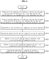
- FIG. 5 is a flowchart illustrating a method for determining the degradation degree of the battery according to an embodiment of the present disclosure. The method of FIG. 5 may be used to determine the degradation degree of the battery where there is at least one peak on the differential capacity curve B.
- step S502 the control unit 120 acquires, from the sensing unit 110, first sensing information indicating the voltage and the current of the battery B for the first period during which the battery B is charged with the first constant current.
- step S504 the control unit 120 acquires, from the sensing unit 110, second sensing information indicating the voltage and the current of the battery B for the second period during which the battery B is discharged with the second constant current.
- step S512 the control unit 120 determines a first differential capacity curve of the battery B based on the first sensing information.
- the first differential capacity curve may be the differential capacity curve 401 of FIG. 4 .
- step S514 the control unit 120 determines a second differential capacity curve of the battery B based on the second sensing information.
- the second differential capacity curve may be the differential capacity curve 402 of FIG. 4 .
- the control unit 120 detects a charge feature point (e.g., P CD_2 ) from the first differential capacity curve.
- the charge feature point (e.g., P CD_2 ) may be a peak located in a predetermined order (e.g., the second order) on the basis of the remaining capacity among all peaks of the first differential capacity curve.
- step S524 the control unit 120 detects a discharge feature point (e.g., P DD_2 ) from the second differential capacity curve.
- the discharge feature point (e.g., P DD_2 ) may be a peak located in the predetermined order (e.g., the second order) on the basis of the remaining capacity among all peaks of the second differential capacity curve.
- the control unit 120 determines the degradation degree of the battery B based on a main difference value.
- the main difference value is an absolute value (e.g.,
- the charge feature value (e.g., V CD_2 ) is a voltage value of the charge feature point (e.g., P CD_2 )
- the discharge feature value e.g., V DD_2
- the control unit 120 determines the degradation degree of the battery B from a first data table that records a correlation between the main difference value determined in the step S530 and the degradation degree, using the main difference value as an index.
- the first data table may be stored in the memory unit 130. As the hysteresis characteristics of the battery B become stronger, the main difference value tends to increase. Accordingly, a larger main difference value may be associated with a higher degradation degree in the first data table.
- FIG. 6 is a flowchart illustrating a method for determining the degradation degree of the battery according to a second embodiment of the present disclosure. The method of FIG. 6 may be used to determine the degradation degree of the battery B where there are at least two peaks on the differential capacity curve.
- step S602 the control unit 120 acquires, from the sensing unit 110, first sensing information indicating the voltage and the current of the battery B for the first period during which the battery B is charged with the first constant current.
- step S604 the control unit 120 acquires, from the sensing unit 110, second sensing information indicating the voltage and current of the battery B for the second period during which the battery B is discharged with the second constant current.
- step S612 the control unit 120 determines a first differential capacity curve of the battery B based on the first sensing information.
- the first differential capacity curve may be the differential capacity curve 401 of FIG. 4 .
- step S614 the control unit 120 determines a second differential capacity curve of the battery B based on the second sensing information.
- the second differential capacity curve may be the differential capacity curve 402 of FIG. 4 .
- step S622 the control unit 120 detects first to n th charge feature points from the first differential capacity curve.
- n is a natural number of 2 or greater, and is a predetermined value indicating the number that is equal to or less than the total number of peaks located on the first differential capacity curve.
- the i th charge feature point may be a peak located in the i th order among the first to n th charge feature points on the basis of the remaining capacity.
- step S624 the control unit 120 detects first to n th discharge feature points from the second differential capacity curve.
- the i th discharge feature point may be a peak located in the i th order among the first to n th discharge feature points on the basis of the remaining capacity.
- the control unit 120 determines the degradation degree of the battery B based on first to n th main difference values.
- the i th main difference value may be an absolute value of a difference between an i th charge feature value and an i th discharge feature value.
- the i th charge feature value is a voltage value of the i th charge feature point
- the i th discharge feature value is a voltage value of the i th discharge feature point.
- the control unit 120 determines a first degradation factor from the first to n th main difference values.
- the control unit 120 may determine the first degradation factor using the following Equation 1.
- Equation 1 ⁇ V i is the i th main difference value, V CD_i is the i th charge feature value, V DD_i is the i th discharge feature value, ⁇ i is an i th predetermined weight, and F deg is the first degradation factor.
- ⁇ i may be a preset value based on an increase of the i th charge feature value and a decrease of the i th discharge feature value as the battery B degrades.
- the increase of the i th charge feature value may be a ratio of the i th charge feature value to the i th initial charge feature value.
- the decrease of the i th discharge feature value may be a ratio of the i th discharge feature value to the i th initial discharge feature value.
- Equation 1 may be represented as the following Equation 2.
- the control unit 120 determines the degradation degree of the battery B from a second data table that records a correlation between the first degradation factor F deg determined in the step S630 and the degradation degree, using the first degradation factor as an index.
- the second data table may be stored in the memory unit 130. As the hysteresis characteristics of the battery B become stronger, each of the first to n th main difference values tends to increase. Accordingly, a larger first degradation factor may be associated with a higher degradation degree in the second data table.
- FIG. 7 is a flowchart illustrating a method for determining the degradation of the battery according to a third embodiment of the present disclosure. The method of FIG. 7 may be used to determine the degradation degree of the battery B where there is at least one peak on the differential capacity curve.
- step S702 the control unit 120 acquires, from the sensing unit 110, first sensing information indicating the voltage and the current of the battery B for the first period during which the battery B is charged with the first constant current.
- step S704 the control unit 120 acquires, from the sensing unit 110, second sensing information indicating the voltage and current of the battery B for the second period during which the battery B is discharged with the second constant current.
- step S712 the control unit 120 determines a first differential capacity curve of the battery B based on the first sensing information.
- the first differential capacity curve may be the differential capacity curve 401 of FIG. 4 .
- step S714 the control unit 120 determines a second differential capacity curve of the battery B based on the second sensing information.
- the second differential capacity curve may be the differential capacity curve 402 of FIG. 4 .
- step S722 the control unit 120 detects a charge feature point (e.g., P CD_2 ) from the first differential capacity curve.
- the charge feature point (e.g., P CD_2 ) may be a peak located in a predetermined order on the basis of the remaining capacity among all peaks of the first differential capacity curve.
- step S724 the control unit 120 detects a discharge feature point (e.g., P DD_2 ) from the second differential capacity curve.
- the discharge feature point (e.g., P DD_2 ) may be a peak located in the predetermined order on the basis of the remaining capacity among all peaks of the second differential capacity curve.
- the control unit 120 determines the degradation degree of the battery B based on a first sub-difference value (e.g.,
- a first sub-difference value e.g.,
- a second sub-difference value that is an absolute value of a difference between a discharge feature value (e.g., V DD_2 ) and an initial discharge
- the initial charge feature value (e.g., V CI_2 ) may be a voltage value of the peak (e.g., P CI_2 ) located in the predetermined order on the differential capacity curve 301.
- the initial discharge feature value (e.g., V DI_2 ) may be a voltage value of the peak (e.g., P DI_2 ) located in the predetermined order on the differential capacity curve 302.
- the charge feature value (e.g., V CD_2 ) is a voltage value of the charge feature point (e.g., V CD_2 )
- the discharge feature value (e.g., V DD_2 ) is a voltage value of the discharge feature point (e.g., V DD_2 ).
- the control unit 120 may determine the sum of the product of the first sub-difference value and a first transform coefficient and the product of the second sub-difference value and a second transform coefficient as a second degradation factor.
- the first transform coefficient and the second transform coefficient may be values for adjusting a relative size between the first sub-difference value and the second sub-difference value since the first sub-difference value and the second sub-difference value may be different from each other when the degradation degree of the battery B is the same.
- the first transform coefficient may be a preset positive number based on a correlation between the degradation degree of the battery B and the first sub-difference value.
- the second transform coefficient may be a preset positive number based on a correlation between the degradation degree of the battery B and the second sub-difference value.
- the control unit 120 determines the degradation degree of the battery B from a third data table that records a correlation between the second degradation factor determined in the step S730 and the degradation degree using the second degradation factor as an index.
- the third data table may be stored in the memory unit 130. As the hysteresis characteristics of the battery B become stronger, the first sub-difference value and the second sub-difference value tend to increase at different rates. Accordingly, a larger second degradation factor is associated with a higher degradation degree in the third data table.
- the control unit 120 may determine that the battery B is abnormal. In this case, the control unit 120 may output a message for notifying that the battery B is abnormal to the user using the interface unit 140, instead of determining the degradation degree of the battery B.
- control unit 120 may output a message for notifying the degradation degree of the battery to the user using the interface unit 140.
Landscapes
- Physics & Mathematics (AREA)
- General Physics & Mathematics (AREA)
- Engineering & Computer Science (AREA)
- Power Engineering (AREA)
- Secondary Cells (AREA)
- Health & Medical Sciences (AREA)
- General Health & Medical Sciences (AREA)
- Medical Informatics (AREA)
- Charge And Discharge Circuits For Batteries Or The Like (AREA)
- Tests Of Electric Status Of Batteries (AREA)
Abstract
Description
- The present disclosure relates to technology for determining a degradation degree of a battery.
- The present application claims priority to
Korean Patent Application No. 10-2019-0056467 - Recently, there has been a dramatic increase in demand for portable electronic products such as laptop computers, video cameras and mobile phones, and with the extensive development of electric vehicles, accumulators for energy storage, robots and satellites, many studies are being made on high performance batteries that can be recharged repeatedly.
- Currently, commercially available batteries include nickel-cadmium batteries, nickel-hydrogen batteries, nickel-zinc batteries, lithium batteries and the like, and among them, lithium batteries have little or no memory effect, and thus they are gaining more attention than nickel-based batteries for their advantages that recharging can be done whenever it is convenient, the self-discharge rate is very low and the energy density is high.
- The degradation degree of a battery is determined from a capacity curve indicating a correlation between voltage and remaining capacity of the battery. However, in the capacity curve, there is a remaining capacity range in which voltage changes are not clearly observed, it is difficult to accurately determine the degradation degree of the battery.
- To overcome the disadvantage of the capacity curve, the degradation degree of the battery may be determined from a differential voltage curve of the battery using the differential voltage analysis (DVA). However, the differential voltage curve acquired by performing only one of the charge process and the discharge process of the battery does not sufficiently include information about the hysteresis characteristics of the battery.
- The present disclosure is designed to solve the above-described problem, and therefore the present disclosure is directed to providing an apparatus, method and battery pack for determining a degradation degree of a battery using both a differential capacity curve acquired from the charge process of the battery and a differential capacity curve acquired from the discharge process of the battery.
- These and other objects and advantages of the present disclosure may be understood by the following description and will be apparent from the embodiments of the present disclosure. In addition, it will be easily understood that the objects and advantages of the present disclosure may be realized by the means set forth in the appended claims and a combination thereof.
- An apparatus for determining a degradation degree of a battery according to an aspect of the present disclosure comprises a sensing unit configured to generate first sensing information indicating a voltage and a current of the battery for a first period during which the battery is charged with a first constant current and second sensing information indicating a voltage and a current of the battery for a second period during which the battery is discharged with a second constant current, and a control unit operably coupled to the sensing unit. The control unit is configured to determine a first differential capacity curve of the battery based on the first sensing information. The control unit is configured to detect a first charge feature point from the first differential capacity curve. The control unit is configured to determine a second differential capacity curve of the battery based on the second sensing information. The control unit is configured to detect a first discharge feature point from the second differential capacity curve. The control unit is configured to determine the degradation degree of the battery based on a first charge feature value and a first discharge feature value. The first charge feature value is a voltage value of the first charge feature point. The first discharge feature value is a voltage value of the first discharge feature point.
- The control unit may be configured to determine, as the first charge feature point, a peak located in a first predetermined order among a predetermined number of peaks located on the first differential capacity curve. The control unit may be configured to determine, as the first discharge feature point, a peak located in the first predetermined order among a predetermined number of peaks located on the second differential capacity curve.
- The control unit may be configured to determine a first main difference value indicating an absolute value of a difference between the first charge feature value and the first discharge feature value. The control unit may be configured to determine the degradation degree of the battery from a first data table that records a correlation between the first main difference value and the degradation degree, using the first main difference value as an index.
- When the predetermined number is 2 or greater, the control unit may be configured to determine, as a second charge feature point, a peak located in a second predetermined order among the predetermined number of peaks located on the first differential capacity curve. The control unit may be configured to determine, as a second discharge feature point, a peak located in the second predetermined order among the predetermined number of peaks located on the second differential capacity curve. The control unit may be configured to determine a second main difference value indicating an absolute value of a difference between a second charge feature value and a second discharge feature value. The second charge feature value is a voltage value of the second charge feature point. The second discharge feature value is a voltage value of the second discharge feature point.
- When the predetermined number is 2, the control unit may be configured to determine a first degradation factor using the following Equation:

- The control unit may be configured to determine a first sub-difference value indicating an absolute value of a difference between the first charge feature value and a first initial charge feature value. The control unit may be configured to determine a second sub-difference value indicating an absolute value of a difference between the first discharge feature value and a first initial discharge feature value. The control unit may be configured to determine the degradation degree of the battery based on the first sub-difference value and the second sub-difference value.
- The control unit may be configured to determine, as a second degradation factor, a sum of a product of the first sub-difference value and a first transform coefficient and a product of the second sub-difference value and a second transform coefficient. The control unit may be configured to determine the degradation degree of the battery from a third data table that records a correlation between the second degradation factor and the degradation degree, using the second degradation factor as an index.
- A battery pack according to another aspect of the present disclosure comprises the apparatus.
- A method for determining a degradation degree of a battery according to still another aspect of the present disclosure comprises acquiring first sensing information indicating a voltage and a current of the battery for a first period during which the battery is charged with a first constant current, acquiring second sensing information indicating a voltage and a current of the battery for a second period during which the battery is discharged with a second constant current, determining a first differential capacity curve of the battery based on the first sensing information, determining a second differential capacity curve of the battery based on the second sensing information, detecting a first charge feature point from the first differential capacity curve, detecting a first discharge feature point from the second differential capacity curve, and determining the degradation degree of the battery based on a first charge feature value and a first discharge feature value. The first charge feature value is a voltage value of the first charge feature point. The first discharge feature value is a voltage value of the first discharge feature point.
- Determining the degradation degree of the battery may comprise determining a first main difference value indicating an absolute value of a difference between the first charge feature value and the first discharge feature value, and determining the degradation degree of the battery from a first data table that records a correlation between the first main difference value and the degradation degree, using the first main difference value as an index.
- According to at least one of the embodiments of the present disclosure, it is possible to determine a degradation degree of a battery using both a differential capacity curve acquired from the charge process of the battery and a differential capacity curve acquired from the discharge process of the battery. The hysteresis characteristics of the battery has a strong correlation with the degradation degree of the battery, and thus it is possible to determine the degradation degree of the battery more accurately when both the two differential capacity curves are used than when only one differential capacity curve is used.
- The effects of the present disclosure are not limited to the above-mentioned effects, and these and other effects will be clearly understood by those skilled in the art from the appended claims.
- The accompanying drawings illustrate a preferred embodiment of the present disclosure, and together with the detailed description of the present disclosure described below, serve to provide a further understanding of the technical aspects of the present disclosure, and thus the present disclosure should not be construed as being limited to the drawings.
-
FIG. 1 is a diagram illustrating a configuration of a battery pack according to an embodiment of the present disclosure. -
FIG. 2 is a graph illustrating a capacity curve of a battery when the battery is at the beginning of life. -
FIG. 3 is a graph illustrating a differential capacity curve determined from the capacity curve ofFIG. 2 . -
FIG. 4 is a graph illustrating a differential capacity curve of a battery when the battery at the beginning of life degrades. -
FIG. 5 is a flowchart illustrating a method for determining a degradation degree of a battery according to a first embodiment of the present disclosure. -
FIG. 6 is a flowchart illustrating a method for determining a degradation degree of a battery according to a second embodiment of the present disclosure. -
FIG. 7 is a flowchart illustrating a method for determining a degradation degree of a battery according to a third embodiment of the present disclosure. - Hereinafter, the preferred embodiments of the present disclosure will be described in detail with reference to the accompanying drawings. Prior to the description, it should be understood that the terms or words used in the specification and the appended claims should not be construed as being limited to general and dictionary meanings, but rather interpreted based on the meanings and concepts corresponding to the technical aspects of the present disclosure on the basis of the principle that the inventor is allowed to define the terms appropriately for the best explanation.
- Therefore, the embodiments described herein and illustrations shown in the drawings are just a most preferred embodiment of the present disclosure, but not intended to fully describe the technical aspects of the present disclosure, so it should be understood that a variety of other equivalents and modifications could have been made thereto at the time that the application was filed.
- The terms including the ordinal number such as "first", "second" and the like, are used to distinguish one element from another among various elements, but not intended to limit the elements by the terms.
- Unless the context clearly indicates otherwise, it will be understood that the term "comprises" when used in this specification, specifies the presence of stated elements, but does not preclude the presence or addition of one or more other elements. Additionally, the term "control unit" as used herein refers to a processing unit of at least one function or operation, and may be implemented by hardware or software alone or in combination.
- In addition, throughout the specification, it will be further understood that when an element is referred to as being "connected to" another element, it can be directly connected to the other element or intervening elements may be present.
-
FIG. 1 is a diagram illustrating a configuration of a battery pack according to an embodiment of the present disclosure. - Referring to
FIG. 1 , thebattery pack 10 is provided to be installed in an electrical system 1 (e.g., an electric vehicle), and includes a battery B, a switch SW and anapparatus 100. - Positive and negative terminals of the battery B are electrically connected to the
apparatus 100. The battery B includes at least one unit cell. The unit cell may be, for example, a lithium ion battery. The type of the unit cell is not limited to the lithium ion battery, and any other type of battery cell that can be repeatedly recharged may be used as the unit cell. - The switch SW is installed on a path of current for the charge and discharge of the battery B. While the switch SW is turned on, the battery B may be charged and discharged. The switch SW may be a mechanical relay that is turned on or off by the magnetic force of a coil or a semiconductor switch such as a Metal Oxide Semiconductor Field Effect transistor (MOSFET). While the switch SW is turned off, the charge and discharge of the battery B is stopped. The switch SW may be turned on in response to a first switching signal. The switch SW may be turned off in response to a second switching signal.
- The
apparatus 100 is provided to determine a degradation degree of the battery B. The degradation degree may be a value that increases as the battery B degrades. - The
apparatus 100 includes asensing unit 110, acontrol unit 120 and amemory unit 130. Theapparatus 100 may further include at least one of aninterface unit 140 and aswitch driver 200. - The
sensing unit 110 includes a voltage sensor 111 and acurrent sensor 112. - The voltage sensor 111 is electrically connected to the positive terminal and the negative terminal of the battery B. The voltage sensor 111 is configured to measure a voltage across the battery B at each unit time (e.g., 0.01 sec) while the battery B is charged or discharged. The
current sensor 112 is installed on a charge/discharge path of the battery B. Thecurrent sensor 112 is configured to measure the current of the battery B at each unit time while the battery B is charged or discharged. - The
sensing unit 110 is configured to output sensing information indicating the voltage and the current of the battery B at each unit time to thecontrol unit 120. - The
control unit 120 may be implemented in hardware using at least one of application specific integrated circuits (ASICs), digital signal processors (DSPs), digital signal processing devices (DSPDs), programmable logic devices (PLDs), field programmable gate arrays (FPGAs), microprocessors and electrical units for performing other functions. - The
control unit 120 is operably coupled to at least one of thesensing unit 110, thememory unit 130, theinterface unit 140 and theswitch driver 200. - When at least one of predetermined event(s) occurs, the
control unit 120 may command theswitch driver 200 to turn on the switch SW. In other situations, thecontrol unit 120 may command theswitch driver 200 to turn off the switch SW. - The
control unit 120 is configured to store data indicating a voltage history, a current history and a remaining capacity history of the battery B in thememory unit 130 based on the sensing information from thesensing unit 110. The history of a parameter refers to a time series change of the corresponding parameter over a certain or specific period. The voltage history, the current history and the remaining capacity history of the battery B may be those for the same or different periods. The remaining capacity of the battery B indicates an amount of charge stored in the battery B. - The
control unit 120 determines a first capacity curve and a second capacity curve of the battery B. - The first capacity curve indicates a correlation between the voltage history and the remaining capacity history, acquired for a period (hereinafter referred to as a "first period") during which the battery B is charged with a constant current of a first current rate (e.g., 0.02C) from a first state of charge (SOC) (e.g., 5%) or less to a second SOC (e.g., 95%) or more. The first capacity curve is based on first sensing information indicating the voltage and the current of battery B at each unit time, output by the
sensing unit 110 for the first period. Thecontrol unit 120 may control theswitch driver 200 to allow the charge current of the first current rate to flow through the battery B for the first period. - The second capacity curve indicates a correlation between the voltage history and the remaining capacity history, acquired for a period (hereinafter referred to as a "second period") during which the battery B is discharged with a constant current of a second current rate from the second SOC or more to the first SOC or less. The second capacity curve is based on second sensing information indicating the voltage and the current of the battery B at each unit time, output by the
sensing unit 110 for the second period. Thecontrol unit 120 may control theswitch driver 200 to allow the discharge current of the second current rate to flow through the battery B for the second period. The second current rate may be equal to or different from the first current rate. - The
control unit 120 may determine a voltage change dV and a remaining capacity change dQ of the battery B at each unit time from the first capacity curve. Thecontrol unit 120 may store, in thememory unit 130, a first data set indicating a correlation of the voltage V, the remaining capacity Q, the voltage change dV and the remaining capacity change dQ of the battery B at each unit time, determined from the first capacity curve. - The
control unit 120 may determine a first differential capacity curve from the first data set. The first differential capacity curve indicates a relationship between the voltage V of the battery B for the first period and a ratio dQ/dV of the remaining capacity change dQ of the battery B to the voltage change dV of the battery B, and may be referred to as a first V-dQ/dV curve. - The
control unit 120 may determine a voltage change dV and a remaining capacity change dQ of the battery B at each unit time from the second capacity curve. Thecontrol unit 120 may store, in thememory unit 130, a second data set indicating a correlation of the voltage V, the remaining capacity Q, the voltage change dV and the remaining capacity change dQ of the battery B at each unit time, determined from the second capacity curve. - The
control unit 120 may determine a second differential capacity curve from the second data set. The second differential capacity curve indicates a relationship between the voltage V of the battery B for the second period and a ratio dQ/dV of the remaining capacity change dQ of the battery B to the voltage change dV of the battery B, and may be referred to as a second V-dQ/dV curve. - The
memory unit 130 is operably coupled to thecontrol unit 120. Thememory unit 130 may be also operably coupled to thesensing unit 110. Thememory unit 130 is configured to store the sensing information from thesensing unit 110. Thememory unit 130 may store data and programs required for the calculation operation by thecontrol unit 120. Thememory unit 130 may store data indicating the results of the calculation operation by thecontrol unit 120. - The
memory unit 130 may include, for example, at least one type of storage medium of flash memory type, hard disk type, Solid State Disk (SSD) type, Silicon Disk Drive (SDD) type, multimedia card micro type, random access memory (RAM), static random access memory (SRAM), read-only memory (ROM), electrically erasable programmable read-only memory (EEPROM) and programmable read-only memory (PROM). - The
switch driver 200 is electrically coupled to theapparatus 100 and the switch SW. Theswitch driver 200 is configured to selectively output the first switching signal or the second switching signal to the switch SW in response to the command from theapparatus 100. - The
interface unit 140 is configured to support wired or wireless communication between thecontrol unit 120 and a high-level controller 2 (e.g., an Electronic Control Unit (ECU)) of theelectrical system 1. The wired communication may be, for example, controller area network (CAN) communication, and the wireless communication may be, for example, Zigbee or Bluetooth communication. The communication protocol is not limited to a particular type, and may include any type of communication protocol that supports the wired or wireless communication between thecontrol unit 120 and the high-level controller 2. Theinterface unit 140 may include an output device such as a display or a speaker to provide the process results about the degradation degree of the battery B performed by thecontrol unit 120 in a form that allows the user to recognize. Theinterface unit 140 may include an input device such as a mouse and a keyboard to receive an input of data from the user. -
FIG. 2 is a graph illustrating the capacity curve of the battery when the battery is at the beginning of life (BOL), andFIG. 3 is a graph illustrating the differential capacity curve determined from the capacity curve ofFIG. 2 . - The maximum capacity Qmax of the battery B may be the remaining capacity of the battery B when the battery B is fully charged, that is, when the SOC of the battery B is 100%. The maximum capacity Qmax of the battery B gradually decreases as the battery B degrades.
- Referring to
FIG. 2 , thecapacity curve 201 indicates a correlation between the voltage V and the remaining capacity Q of the battery B, acquired through the charge process of the battery B with a constant current of a predetermined current rate with the increasing SOC of the battery B at BOL from 0% to 100%. - The
capacity curve 202 indicates a correlation between the voltage V and the remaining capacity Q of the battery B, acquired through the discharge process of the battery B with a constant current of a predetermined current rate with the decreasing SOC of the battery B at BOL from 100% to 0%. - Due to the hysteresis characteristics of the battery B, a difference between voltage of the
capacity curve 201 and voltage of thecapacity curve 202 at the same remaining capacity is equal to or larger than a predetermined threshold in at least part of the remaining capacity range between 0 and Qmax. - Referring to
FIG. 3 , thedifferential capacity curve 301 is determined from a relationship between the voltage history and the remaining capacity history indicated by thecapacity curve 201. Thedifferential capacity curve 302 is determined from a relationship between the voltage history and the remaining capacity history indicated by thecapacity curve 202. For ease of understanding, thedifferential capacity curve 301 and thedifferential capacity curve 302 are shown above and below dQ/dV = 0 Ah/V respectively. - The total number of peaks PCI_1, PCI_2, PCI_3 located on the
differential capacity curve 301 and the number of peaks PDI_1, PDI_2, PDI_3 located on thedifferential capacity curve 302 may be equal. The total number of peaks located on each of thedifferential capacity curve 301 and thedifferential capacity curve 302 relies on the electrode material, etc. of the battery B. Accordingly, the total number of peaks located on each of thedifferential capacity curve 301 and thedifferential capacity curve 302 may be constant, even though the battery B degrades. Hereinafter, assume that the total number of peaks PCI_1, PCI_2, PCI_3 appearing in thedifferential capacity curve 301 and the total number of peaks PDI_1, PDI_2, PDI_3 located on thedifferential capacity curve 302 is 3 respectively. - The
memory unit 130 may store charge feature values (referred to as 'initial charge feature values') indicating voltage values VCI_1, VCI_2, VCI_3 of the peaks Pci_i, PCI_2, PCI_3 located on thedifferential capacity curve 301, respectively. - The
memory unit 130 may store discharge feature values (referred to as 'initial discharge feature values') indicating voltage values VDI_1, VDI_2, VDI_3 of the peaks PDI_1, PDI_2, PDI_3 located on thedifferential capacity curve 302, respectively. - The inventor recognized the fact that the hysteresis characteristics of the battery B become severer as the battery B degrades from the charge and discharge test results of a battery of the same specifications as the battery B.
-
FIG. 4 is a graph illustrating the differential capacity curve of the battery when the battery at BOL degrades. - Referring to
FIG. 4 , thedifferential capacity curve 401 is determined from a relationship between the voltage history and the remaining capacity history for the first period. Thedifferential capacity curve 402 is determined from a relationship between the voltage history and the remaining capacity history for the second period. For ease of understanding, thedifferential capacity curve 401 and thedifferential capacity curve 402 are shown above and below dQ/dV = 0. - The
differential capacity curve 401 has the same number of peaks PCD_1, PCD_2, PCD_3 as the peaks PCI_1, PCI_2, PCI_3 appearing in thedifferential capacity curve 301. Thedifferential capacity curve 402 has the same number of peaks PDD_1, PDD_2, PDD_3 as the peaks PDI_1, PDI_2, PDI_3 appearing in thedifferential capacity curve 302. - In the
differential capacity curve 401, the peak PCD_1, the peak PCD_2 and the peak PCD_3 are located in ascending order of the remaining capacity. The peaks PCD_1, PCD_2, PCD_3 appearing in thedifferential capacity curve 401 correspond to the peaks PCI_1, PCI_2, PCI_3 appearing in thedifferential capacity curve 301 respectively. The peaks PCD_1 , PCD_2, PCD_3 may be referred to as 'charge feature points', and the voltage values of VCD_1, VCD_2, VCD_3 of the peaks PCD_1, PCD_2, PCD_3 may be referred to as 'charge feature values'. - In the
differential capacity curve 402, the peak PDD_1, the peak PDD_2 and the peak PDD_3 are located in ascending order of the remaining capacity. The peaks PDD_1, PDD_2, PDD_3 appearing in thedifferential capacity curve 402 correspond to the peaks PDI_1, PDI_2, PDI_3 appearing in thedifferential capacity curve 302 respectively. The peaks PDD_1, PDD_2, PDD_3 may be referred to as 'discharge feature points', and the voltage values VDD_1, VDD_2, VDD_3 of the peaks P DD_1, PDD_2, PDD_3 may be referred to as 'discharge feature values'. - Referring to
FIGS. 2 to 4 , it can be seen that as the battery B degrades, (I) the charge feature values of VCD_1, VCD_2, VCD_3 of the peaks PCD_1, PCD_2, PCD_3 located on thedifferential capacity curve 401 increase from the initial charge feature values VCI_1, VCI_2, VCI_3 of the peaks PCI_1, PCI_2, PCI_3 located in the same order on thedifferential capacity curve 301, and (II) the discharge feature values of VDD_1, VDD_2, VDD_3 of the peaks PDD_1, PDD_2, PDD_3 located on thedifferential capacity curve 402 decreases from the initial discharge feature values VDI_1, VDI_2, VDI_3 of the peaks PDI_1, PDI_2, PDI_3 located in the same order on thedifferential capacity curve 302. That is, as the battery B degrades, the peaks PCD_1, PCD_2, PCD_3 of thedifferential capacity curve 401 are shifted to higher voltage, and the peaks PDD_1, PDD_2, PDD_3 of thedifferential capacity curve 402 are shifted to lower voltage. - The inventor found that a difference between the voltage values (e.g., VCD_1, VDD_1) of the two peaks (e.g., PCD_1, PDD_1) appearing in the same order (e.g., the first order) on the
differential capacity curve 401 and thedifferential capacity curve 402 has a strong correlation with the degradation degree of the battery B. -
FIG. 5 is a flowchart illustrating a method for determining the degradation degree of the battery according to an embodiment of the present disclosure. The method ofFIG. 5 may be used to determine the degradation degree of the battery where there is at least one peak on the differential capacity curve B. - Referring to
FIGS. 1 to 5 , in step S502, thecontrol unit 120 acquires, from thesensing unit 110, first sensing information indicating the voltage and the current of the battery B for the first period during which the battery B is charged with the first constant current. - In step S504, the
control unit 120 acquires, from thesensing unit 110, second sensing information indicating the voltage and the current of the battery B for the second period during which the battery B is discharged with the second constant current. - In step S512, the
control unit 120 determines a first differential capacity curve of the battery B based on the first sensing information. For example, the first differential capacity curve may be thedifferential capacity curve 401 ofFIG. 4 . - In step S514, the
control unit 120 determines a second differential capacity curve of the battery B based on the second sensing information. For example, the second differential capacity curve may be thedifferential capacity curve 402 ofFIG. 4 . - In step S522, the
control unit 120 detects a charge feature point (e.g., PCD_2) from the first differential capacity curve. The charge feature point (e.g., PCD_2) may be a peak located in a predetermined order (e.g., the second order) on the basis of the remaining capacity among all peaks of the first differential capacity curve. - In step S524, the
control unit 120 detects a discharge feature point (e.g., PDD_2) from the second differential capacity curve. The discharge feature point (e.g., PDD_2) may be a peak located in the predetermined order (e.g., the second order) on the basis of the remaining capacity among all peaks of the second differential capacity curve. - In step S530, the
control unit 120 determines the degradation degree of the battery B based on a main difference value. The main difference value is an absolute value (e.g., | VCD_2 - VDD_2 | ) of a difference between a charge feature value (e.g., VCD_2) and a discharge feature value (e.g., VDD_2). The charge feature value (e.g., VCD_2) is a voltage value of the charge feature point (e.g., PCD_2), and the discharge feature value (e.g., VDD_2) is a voltage value of the discharge feature point (e.g., PDD_2). Thecontrol unit 120 determines the degradation degree of the battery B from a first data table that records a correlation between the main difference value determined in the step S530 and the degradation degree, using the main difference value as an index. - The first data table may be stored in the
memory unit 130. As the hysteresis characteristics of the battery B become stronger, the main difference value tends to increase. Accordingly, a larger main difference value may be associated with a higher degradation degree in the first data table. -
FIG. 6 is a flowchart illustrating a method for determining the degradation degree of the battery according to a second embodiment of the present disclosure. The method ofFIG. 6 may be used to determine the degradation degree of the battery B where there are at least two peaks on the differential capacity curve. - Referring to
FIGS. 1 to 4 and6 , in step S602, thecontrol unit 120 acquires, from thesensing unit 110, first sensing information indicating the voltage and the current of the battery B for the first period during which the battery B is charged with the first constant current. - In step S604, the
control unit 120 acquires, from thesensing unit 110, second sensing information indicating the voltage and current of the battery B for the second period during which the battery B is discharged with the second constant current. - In step S612, the
control unit 120 determines a first differential capacity curve of the battery B based on the first sensing information. For example, the first differential capacity curve may be thedifferential capacity curve 401 ofFIG. 4 . - In step S614, the
control unit 120 determines a second differential capacity curve of the battery B based on the second sensing information. For example, the second differential capacity curve may be thedifferential capacity curve 402 ofFIG. 4 . - In step S622, the
control unit 120 detects first to nth charge feature points from the first differential capacity curve. n is a natural number of 2 or greater, and is a predetermined value indicating the number that is equal to or less than the total number of peaks located on the first differential capacity curve. When i = 1 to n, the ith charge feature point may be a peak located in the ith order among the first to nth charge feature points on the basis of the remaining capacity. - In step S624, the
control unit 120 detects first to nth discharge feature points from the second differential capacity curve. The ith discharge feature point may be a peak located in the ith order among the first to nth discharge feature points on the basis of the remaining capacity. - In step S630, the
control unit 120 determines the degradation degree of the battery B based on first to nth main difference values. When i = 1 to n, the ith main difference value may be an absolute value of a difference between an ith charge feature value and an ith discharge feature value. The ith charge feature value is a voltage value of the ith charge feature point, and the ith discharge feature value is a voltage value of the ith discharge feature point. Subsequently, thecontrol unit 120 determines a first degradation factor from the first to nth main difference values. Thecontrol unit 120 may determine the first degradation factor using the followingEquation 1.
- In
Equation 1, ΔVi is the ith main difference value, VCD_i is the ith charge feature value, VDD_i is the ith discharge feature value, αi is an ith predetermined weight, and Fdeg is the first degradation factor. αi may be a preset value based on an increase of the ith charge feature value and a decrease of the ith discharge feature value as the battery B degrades. The increase of the ith charge feature value may be a ratio of the ith charge feature value to the ith initial charge feature value. The decrease of the ith discharge feature value may be a ratio of the ith discharge feature value to the ith initial discharge feature value. - For example, when n is 2, the
above Equation 1 may be represented as the followingEquation 2.
- The
control unit 120 determines the degradation degree of the battery B from a second data table that records a correlation between the first degradation factor Fdeg determined in the step S630 and the degradation degree, using the first degradation factor as an index. - The second data table may be stored in the
memory unit 130. As the hysteresis characteristics of the battery B become stronger, each of the first to nth main difference values tends to increase. Accordingly, a larger first degradation factor may be associated with a higher degradation degree in the second data table. -
FIG. 7 is a flowchart illustrating a method for determining the degradation of the battery according to a third embodiment of the present disclosure. The method ofFIG. 7 may be used to determine the degradation degree of the battery B where there is at least one peak on the differential capacity curve. - Referring to
FIGS. 1 to 4 and7 , in step S702, thecontrol unit 120 acquires, from thesensing unit 110, first sensing information indicating the voltage and the current of the battery B for the first period during which the battery B is charged with the first constant current. - In step S704, the
control unit 120 acquires, from thesensing unit 110, second sensing information indicating the voltage and current of the battery B for the second period during which the battery B is discharged with the second constant current. - In step S712, the
control unit 120 determines a first differential capacity curve of the battery B based on the first sensing information. For example, the first differential capacity curve may be thedifferential capacity curve 401 ofFIG. 4 . - In step S714, the
control unit 120 determines a second differential capacity curve of the battery B based on the second sensing information. For example, the second differential capacity curve may be thedifferential capacity curve 402 ofFIG. 4 . - In step S722, the
control unit 120 detects a charge feature point (e.g., PCD_2) from the first differential capacity curve. The charge feature point (e.g., PCD_2) may be a peak located in a predetermined order on the basis of the remaining capacity among all peaks of the first differential capacity curve. - In step S724, the
control unit 120 detects a discharge feature point (e.g., PDD_2) from the second differential capacity curve. The discharge feature point (e.g., PDD_2) may be a peak located in the predetermined order on the basis of the remaining capacity among all peaks of the second differential capacity curve. - In step S730, the
control unit 120 determines the degradation degree of the battery B based on a first sub-difference value (e.g., | VCD_2 - VCI_2 | ) that is an absolute value of a difference between a charge feature value (e.g., VCD_2) and an initial charge feature value (e.g., VCI_2) and a second sub-difference value (e.g., | VDD_2 - VDI_2 | ) that is an absolute value of a difference between a discharge feature value (e.g., VDD_2) and an initial discharge feature value (e.g., VDI_2). - The initial charge feature value (e.g., VCI_2) may be a voltage value of the peak (e.g., PCI_2) located in the predetermined order on the
differential capacity curve 301. The initial discharge feature value (e.g., VDI_2) may be a voltage value of the peak (e.g., PDI_2) located in the predetermined order on thedifferential capacity curve 302. - The charge feature value (e.g., VCD_2) is a voltage value of the charge feature point (e.g., VCD_2), and the discharge feature value (e.g., VDD_2) is a voltage value of the discharge feature point (e.g., VDD_2). The
control unit 120 may determine the sum of the product of the first sub-difference value and a first transform coefficient and the product of the second sub-difference value and a second transform coefficient as a second degradation factor. The first transform coefficient and the second transform coefficient may be values for adjusting a relative size between the first sub-difference value and the second sub-difference value since the first sub-difference value and the second sub-difference value may be different from each other when the degradation degree of the battery B is the same. The first transform coefficient may be a preset positive number based on a correlation between the degradation degree of the battery B and the first sub-difference value. The second transform coefficient may be a preset positive number based on a correlation between the degradation degree of the battery B and the second sub-difference value. - The
control unit 120 determines the degradation degree of the battery B from a third data table that records a correlation between the second degradation factor determined in the step S730 and the degradation degree using the second degradation factor as an index. - The third data table may be stored in the
memory unit 130. As the hysteresis characteristics of the battery B become stronger, the first sub-difference value and the second sub-difference value tend to increase at different rates. Accordingly, a larger second degradation factor is associated with a higher degradation degree in the third data table. - When a ratio of one of the first sub-difference value (e.g., | VCD_2 -VCI_2 | ) and the second sub-difference value (e.g., | VDD_2 -VDI_2 | ) to the other exceeds a predetermined range, the
control unit 120 may determine that the battery B is abnormal. In this case, thecontrol unit 120 may output a message for notifying that the battery B is abnormal to the user using theinterface unit 140, instead of determining the degradation degree of the battery B. - When the degradation degree of the battery B is determined according to at least one of the first to third embodiments, the
control unit 120 may output a message for notifying the degradation degree of the battery to the user using theinterface unit 140. - The embodiments of the present disclosure described hereinabove are not implemented only through the apparatus and method, and may be implemented through programs that realize the functions corresponding to the configurations of the embodiments of the present disclosure or recording media having the programs recorded thereon, and such implementation may be easily achieved by those skilled in the art from the disclosure of the embodiments previously described.
- While the present disclosure has been hereinabove described with regard to a limited number of embodiments and drawings, the present disclosure is not limited thereto and it is obvious to those skilled in the art that various modifications and changes may be made thereto within the technical aspects of the present disclosure and the equivalent scope of the appended claims.
- Additionally, as many substitutions, modifications and changes may be made to the present disclosure by those skilled in the art without departing from the technical aspects of the present disclosure, the present disclosure is not limited by the foregoing embodiments and the accompanying drawings, and some or all of the embodiments may be selectively combined to make various modifications to the present disclosure.
Claims (11)
- An apparatus for determining a degradation degree of a battery, the apparatus comprising:a sensing unit configured to generate first sensing information indicating a voltage and a current of the battery for a first period during which the battery is charged with a first constant current and second sensing information indicating a voltage and a current of the battery for a second period during which the battery is discharged with a second constant current; anda control unit operably coupled to the sensing unit,wherein the control unit is configured to:determine a first differential capacity curve of the battery based on the first sensing information,detect a first charge feature point from the first differential capacity curve,determine a second differential capacity curve of the battery based on the second sensing information,detect a first discharge feature point from the second differential capacity curve, anddetermine the degradation degree of the battery based on a first charge feature value and a first discharge feature value,wherein the first charge feature value is a voltage value of the first charge feature point, andthe first discharge feature value is a voltage value of the first discharge feature point.
- The apparatus according to claim 1, wherein the control unit is configured to:determine, as the first charge feature point, a peak located in a first predetermined order among a predetermined number of peaks located on the first differential capacity curve, anddetermine, as the first discharge feature point, a peak located in the first predetermined order among a predetermined number of peaks located on the second differential capacity curve.
- The apparatus according to claim 2, wherein the control unit is configured to determine a first main difference value indicating an absolute value of a difference between the first charge feature value and the first discharge feature value.
- The apparatus according to claim 3, wherein the control unit is configured to determine the degradation degree of the battery from a first data table that records a correlation between the first main difference value and the degradation degree, using the first main difference value as an index.
- The apparatus according to claim 2, wherein the control unit is configured to:when the predetermined number is 2 or greater,determine, as a second charge feature point, a peak located in a second predetermined order among the predetermined number of peaks located on the first differential capacity curve,determine, as a second discharge feature point, a peak located in the second predetermined order among the predetermined number of peaks located on the second differential capacity curve, anddetermine a second main difference value indicating an absolute value of a difference between a second charge feature value and a second discharge feature value,wherein the second charge feature value is a voltage value of the second charge feature point, andthe second discharge feature value is a voltage value of the second discharge feature point.
- The apparatus according to claim 5, wherein when the predetermined number is 2, the control unit is configured to,determine a first degradation factor using the following Equation:
 wherein ΔVi is an ith main difference value, αi is an ith predetermined weight, and Fdeg is the first degradation factor, anddetermine the degradation degree of the battery from a second data table that records a correlation between the first degradation factor and the degradation degree, using the first degradation factor as an index.
 - The apparatus according to claim 1, wherein the control unit is configured to:determine a first sub-difference value indicating an absolute value of a difference between the first charge feature value and a first initial charge feature value,determine a second sub-difference value indicating an absolute value of a difference between the first discharge feature value and a first initial discharge feature value, anddetermine the degradation degree of the battery based on the first sub-difference value and the second sub-difference value.
- The apparatus according to claim 7, wherein the control unit is configured to:determine, as a second degradation factor, a sum of a product of the first sub-difference value and a first transform coefficient and a product of the second sub-difference value and a second transform coefficient, anddetermine the degradation degree of the battery from a third data table that records a correlation between the second degradation factor and the degradation degree, using the second degradation factor as an index.
- A battery pack comprising the apparatus according to any one of claims 1 to 8.
- A method for determining a degradation degree of a battery, the method comprising:acquiring first sensing information indicating a voltage and a current of the battery for a first period during which the battery is charged with a first constant current;acquiring second sensing information indicating a voltage and a current of the battery for a second period during which the battery is discharged with a second constant current;determining a first differential capacity curve of the battery based on the first sensing information;determining a second differential capacity curve of the battery based on the second sensing information;detecting a first charge feature point from the first differential capacity curve;detecting a first discharge feature point from the second differential capacity curve; anddetermining the degradation degree of the battery based on a first charge feature value and a first discharge feature value,wherein the first charge feature value is a voltage value of the first charge feature point, andthe first discharge feature value is a voltage value of the first discharge feature point.
- The method according to claim 10, wherein determining the degradation degree of the battery comprises:determining a first main difference value indicating an absolute value of a difference between the first charge feature value and the first discharge feature value; anddetermining the degradation degree of the battery from a first data table that records a correlation between the first main difference value and the degradation degree, using the first main difference value as an index.
Applications Claiming Priority (2)
| Application Number | Priority Date | Filing Date | Title |
|---|---|---|---|
| KR1020190056467A KR102537607B1 (en) | 2019-05-14 | 2019-05-14 | Apparatus, method and battery pack for determining degradation degree of battery |
| PCT/KR2020/006047 WO2020231086A1 (en) | 2019-05-14 | 2020-05-07 | Device and method for determining degree of degradation of battery, and battery pack comprising device |
Publications (3)
| Publication Number | Publication Date |
|---|---|
| EP3913385A1 true EP3913385A1 (en) | 2021-11-24 |
| EP3913385A4 EP3913385A4 (en) | 2022-03-30 |
| EP3913385B1 EP3913385B1 (en) | 2024-06-05 |
Family
ID=73288990
Family Applications (1)
| Application Number | Title | Priority Date | Filing Date |
|---|---|---|---|
| EP20806580.5A Active EP3913385B1 (en) | 2019-05-14 | 2020-05-07 | Apparatus and method for determining degradation degree of battery and battery pack comprising the apparatus |
Country Status (9)
| Country | Link |
|---|---|
| US (2) | US11852688B2 (en) |
| EP (1) | EP3913385B1 (en) |
| JP (1) | JP7151044B2 (en) |
| KR (1) | KR102537607B1 (en) |
| CN (1) | CN112840221B (en) |
| ES (1) | ES2986504T3 (en) |
| HU (1) | HUE067676T2 (en) |
| PL (1) | PL3913385T3 (en) |
| WO (1) | WO2020231086A1 (en) |
Cited By (2)
| Publication number | Priority date | Publication date | Assignee | Title |
|---|---|---|---|---|
| US11543460B2 (en) | 2019-09-12 | 2023-01-03 | Samsung Electronics Co., Ltd. | Battery state measuring method and battery management system |
| US12248024B2 (en) | 2021-01-25 | 2025-03-11 | Lg Energy Solution, Ltd. | Battery classification apparatus and method |
Families Citing this family (14)
| Publication number | Priority date | Publication date | Assignee | Title |
|---|---|---|---|---|
| KR102537607B1 (en) * | 2019-05-14 | 2023-05-25 | 주식회사 엘지에너지솔루션 | Apparatus, method and battery pack for determining degradation degree of battery |
| ES2991479T3 (en) * | 2019-08-23 | 2024-12-03 | Lg Energy Solution Ltd | Method for predicting the health status of a battery and battery group that employs it |
| KR102887844B1 (en) | 2020-12-29 | 2025-11-17 | 주식회사 엘지에너지솔루션 | Battery diagnosis system, battery diagnosis method, battery pack, and electric vehicle |
| JP2024501510A (en) | 2021-01-08 | 2024-01-12 | エルジー エナジー ソリューション リミテッド | Battery management device and method |
| CN113442787B (en) * | 2021-05-28 | 2023-06-23 | 上海科列新能源技术有限公司 | Abnormal single cell identification method and device, electronic equipment and storage medium |
| KR102674286B1 (en) * | 2021-08-02 | 2024-06-10 | 주식회사 엘지에너지솔루션 | Apparatus and method for managing battery |
| CN114636943B (en) * | 2022-05-12 | 2022-08-30 | 中创新航科技股份有限公司 | Battery device, method for detecting the same, method and device for screening battery cells |
| JP2024031474A (en) * | 2022-08-26 | 2024-03-07 | 株式会社Subaru | Electric vehicle battery management device |
| JP2026514361A (en) * | 2023-08-16 | 2026-05-11 | エルジー エナジー ソリューション リミテッド | Battery degradation indicator information acquisition device and method, battery pack, and electric vehicle |
| KR20250035384A (en) | 2023-09-05 | 2025-03-12 | 효성중공업 주식회사 | Apparatus for estimating life of battery module and life of battery rack using test data of battery cell and method thereof |
| KR20250041528A (en) | 2023-09-18 | 2025-03-25 | 효성중공업 주식회사 | Apparatus for estimating battery life and method thereof |
| KR20250083917A (en) * | 2023-12-01 | 2025-06-10 | 주식회사 엘지에너지솔루션 | Apparatus and method for diagnosing battery |
| KR102757503B1 (en) * | 2024-02-08 | 2025-01-21 | 주식회사 엘지에너지솔루션 | Battery diagnostic device and method |
| CN121552984B (en) * | 2026-01-21 | 2026-04-24 | 绿能慧充数字技术有限公司 | Method for controlling running state of charging pile charging module and storage medium |
Family Cites Families (29)
| Publication number | Priority date | Publication date | Assignee | Title |
|---|---|---|---|---|
| KR20070020322A (en) * | 2003-06-23 | 2007-02-20 | 야자키 소교 가부시키가이샤 | Battery deterioration determination method and apparatus |
| JP4561859B2 (en) * | 2008-04-01 | 2010-10-13 | トヨタ自動車株式会社 | Secondary battery system |
| WO2011036760A1 (en) | 2009-09-25 | 2011-03-31 | トヨタ自動車株式会社 | Secondary battery system |
| JP5682955B2 (en) | 2010-08-04 | 2015-03-11 | Necエナジーデバイス株式会社 | Lithium secondary battery control system and lithium secondary battery state detection method |
| US8680815B2 (en) * | 2010-11-01 | 2014-03-25 | GM Global Technology Operations LLC | Method and apparatus for assessing battery state of health |
| US8531158B2 (en) * | 2010-11-01 | 2013-09-10 | GM Global Technology Operations LLC | Method and apparatus for assessing battery state of health |
| JP5315369B2 (en) | 2011-03-01 | 2013-10-16 | 株式会社日立製作所 | Abnormally charged state detection device and inspection method for lithium secondary battery |
| JP5741348B2 (en) | 2011-09-21 | 2015-07-01 | トヨタ自動車株式会社 | Secondary battery system and vehicle |
| JP5662968B2 (en) * | 2012-06-19 | 2015-02-04 | 株式会社日立製作所 | Secondary battery inspection system, charger / discharger, and inspection method |
| JP5846054B2 (en) | 2012-06-22 | 2016-01-20 | トヨタ自動車株式会社 | Diagnostic device and diagnostic method |
| JP5354416B1 (en) * | 2012-11-05 | 2013-11-27 | 東洋システム株式会社 | Secondary battery evaluation method and evaluation program |
| WO2014083813A1 (en) * | 2012-11-30 | 2014-06-05 | 株式会社Gsユアサ | Device for detecting decrease in storage element functionality, method for detecting decrease in functionality, and storage system |
| JP2014139897A (en) * | 2013-01-21 | 2014-07-31 | Toyota Industries Corp | Secondary battery system |
| JP2015060761A (en) | 2013-09-19 | 2015-03-30 | 株式会社東芝 | Deterioration diagnostic system and deterioration diagnostic method of secondary battery |
| EP2990818B1 (en) | 2014-09-01 | 2019-11-27 | Yokogawa Electric Corporation | Secondary battery capacity measurement system and secondary battery capacity measurement method |
| JP6123844B2 (en) * | 2014-09-01 | 2017-05-10 | 横河電機株式会社 | Secondary battery capacity measuring system and secondary battery capacity measuring method |
| JP2016085062A (en) * | 2014-10-23 | 2016-05-19 | エンネット株式会社 | Device and method for determining battery deterioration |
| JP6299623B2 (en) * | 2015-02-10 | 2018-03-28 | トヨタ自動車株式会社 | Initial charging method for lithium-ion battery |
| JP6500789B2 (en) | 2016-01-19 | 2019-04-17 | トヨタ自動車株式会社 | Control system of secondary battery |
| JP2017133870A (en) | 2016-01-26 | 2017-08-03 | トヨタ自動車株式会社 | Device for detecting abnormal degradation of lithium ion secondary battery and method for detecting abnormal degradation |
| JP6477610B2 (en) * | 2016-06-22 | 2019-03-06 | 横河電機株式会社 | Secondary battery capacity measuring system and secondary battery capacity measuring method |
| EP3563465B1 (en) * | 2016-12-29 | 2023-08-02 | Vito NV | Hybrid battery charger/tester |
| JP2018205139A (en) * | 2017-06-05 | 2018-12-27 | 三菱自動車工業株式会社 | Secondary battery system |
| JP2019045351A (en) | 2017-09-04 | 2019-03-22 | 三菱自動車工業株式会社 | Secondary battery system |
| JP2019056595A (en) * | 2017-09-20 | 2019-04-11 | 三菱自動車工業株式会社 | Secondary battery system |
| KR20190056467A (en) | 2017-11-16 | 2019-05-27 | 동아오토 주식회사 | Heater for electric vehicle and temperature control method of the same |
| KR101930646B1 (en) * | 2017-11-22 | 2019-03-11 | 주식회사 포스코아이씨티 | Apparatus and Method for Estimating Capacity of Battery Using Second Order Differential Voltage Curve |
| KR102537607B1 (en) * | 2019-05-14 | 2023-05-25 | 주식회사 엘지에너지솔루션 | Apparatus, method and battery pack for determining degradation degree of battery |
| KR102766401B1 (en) * | 2019-09-19 | 2025-02-10 | 주식회사 엘지에너지솔루션 | Battery management apparatus, battery management method, battery pack and electric vehicle |
-
2019
- 2019-05-14 KR KR1020190056467A patent/KR102537607B1/en active Active
-
2020
- 2020-05-07 US US17/417,890 patent/US11852688B2/en active Active
- 2020-05-07 EP EP20806580.5A patent/EP3913385B1/en active Active
- 2020-05-07 JP JP2021515148A patent/JP7151044B2/en active Active
- 2020-05-07 WO PCT/KR2020/006047 patent/WO2020231086A1/en not_active Ceased
- 2020-05-07 ES ES20806580T patent/ES2986504T3/en active Active
- 2020-05-07 HU HUE20806580A patent/HUE067676T2/en unknown
- 2020-05-07 CN CN202080005703.7A patent/CN112840221B/en active Active
- 2020-05-07 PL PL20806580.5T patent/PL3913385T3/en unknown
-
2023
- 2023-11-01 US US18/386,240 patent/US12498426B2/en active Active
Cited By (2)
| Publication number | Priority date | Publication date | Assignee | Title |
|---|---|---|---|---|
| US11543460B2 (en) | 2019-09-12 | 2023-01-03 | Samsung Electronics Co., Ltd. | Battery state measuring method and battery management system |
| US12248024B2 (en) | 2021-01-25 | 2025-03-11 | Lg Energy Solution, Ltd. | Battery classification apparatus and method |
Also Published As
| Publication number | Publication date |
|---|---|
| KR20200131629A (en) | 2020-11-24 |
| JP2022510075A (en) | 2022-01-26 |
| US11852688B2 (en) | 2023-12-26 |
| HUE067676T2 (en) | 2024-11-28 |
| US12498426B2 (en) | 2025-12-16 |
| KR102537607B1 (en) | 2023-05-25 |
| EP3913385B1 (en) | 2024-06-05 |
| JP7151044B2 (en) | 2022-10-12 |
| US20220075000A1 (en) | 2022-03-10 |
| PL3913385T3 (en) | 2024-10-07 |
| ES2986504T3 (en) | 2024-11-11 |
| WO2020231086A1 (en) | 2020-11-19 |
| CN112840221B (en) | 2023-09-01 |
| EP3913385A4 (en) | 2022-03-30 |
| CN112840221A (en) | 2021-05-25 |
| US20240061050A1 (en) | 2024-02-22 |
Similar Documents
| Publication | Publication Date | Title |
|---|---|---|
| EP3913385B1 (en) | Apparatus and method for determining degradation degree of battery and battery pack comprising the apparatus | |
| EP3835802B1 (en) | Apparatus and method for determining degradation state of battery, battery pack and electric vehicle | |
| EP3982141B1 (en) | Battery management apparatus, battery management method, battery pack and electric vehicle | |
| US11460506B2 (en) | Apparatus and method for determining differential voltage curve of battery and battery pack comprising the apparatus | |
| US20230023014A1 (en) | Battery Management System, Battery Pack, Electric Vehicle and Battery Management Method | |
| CN115943316B (en) | Battery diagnostic equipment, battery diagnostic methods, battery packs and electric vehicles | |
| EP4725752A2 (en) | Battery management system, battery management method, battery pack and electric vehicle | |
| US12308689B2 (en) | Battery management system, battery management method, battery pack and electric vehicle | |
| US12344120B2 (en) | Battery management system, battery management method, battery pack, and electric vehicle | |
| US20260048680A1 (en) | Battery Management System, Battery Management Method, Battery Pack, and Electric Vehicle |
Legal Events
| Date | Code | Title | Description |
|---|---|---|---|
| STAA | Information on the status of an ep patent application or granted ep patent |
Free format text: STATUS: THE INTERNATIONAL PUBLICATION HAS BEEN MADE |
|
| PUAI | Public reference made under article 153(3) epc to a published international application that has entered the european phase |
Free format text: ORIGINAL CODE: 0009012 |
|
| STAA | Information on the status of an ep patent application or granted ep patent |
Free format text: STATUS: REQUEST FOR EXAMINATION WAS MADE |
|
| 17P | Request for examination filed |
Effective date: 20210820 |
|
| AK | Designated contracting states |
Kind code of ref document: A1 Designated state(s): AL AT BE BG CH CY CZ DE DK EE ES FI FR GB GR HR HU IE IS IT LI LT LU LV MC MK MT NL NO PL PT RO RS SE SI SK SM TR |
|
| A4 | Supplementary search report drawn up and despatched |
Effective date: 20220228 |
|
| RAP3 | Party data changed (applicant data changed or rights of an application transferred) |
Owner name: LG ENERGY SOLUTION, LTD. |
|
| RIC1 | Information provided on ipc code assigned before grant |
Ipc: G01R 31/3842 20190101ALI20220222BHEP Ipc: G01R 31/392 20190101AFI20220222BHEP |
|
| DAV | Request for validation of the european patent (deleted) | ||
| DAX | Request for extension of the european patent (deleted) | ||
| STAA | Information on the status of an ep patent application or granted ep patent |
Free format text: STATUS: EXAMINATION IS IN PROGRESS |
|
| 17Q | First examination report despatched |
Effective date: 20230922 |
|
| GRAP | Despatch of communication of intention to grant a patent |
Free format text: ORIGINAL CODE: EPIDOSNIGR1 |
|
| STAA | Information on the status of an ep patent application or granted ep patent |
Free format text: STATUS: GRANT OF PATENT IS INTENDED |
|
| GRAS | Grant fee paid |
Free format text: ORIGINAL CODE: EPIDOSNIGR3 |
|
| INTG | Intention to grant announced |
Effective date: 20240405 |
|
| GRAA | (expected) grant |
Free format text: ORIGINAL CODE: 0009210 |
|
| STAA | Information on the status of an ep patent application or granted ep patent |
Free format text: STATUS: THE PATENT HAS BEEN GRANTED |
|
| P01 | Opt-out of the competence of the unified patent court (upc) registered |
Effective date: 20240412 |
|
| AK | Designated contracting states |
Kind code of ref document: B1 Designated state(s): AL AT BE BG CH CY CZ DE DK EE ES FI FR GB GR HR HU IE IS IT LI LT LU LV MC MK MT NL NO PL PT RO RS SE SI SK SM TR |
|
| REG | Reference to a national code |
Ref country code: CH Ref legal event code: EP |
|
| REG | Reference to a national code |
Ref country code: DE Ref legal event code: R096 Ref document number: 602020032073 Country of ref document: DE |
|
| REG | Reference to a national code |
Ref country code: IE Ref legal event code: FG4D |
|
| REG | Reference to a national code |
Ref country code: NL Ref legal event code: FP |
|
| REG | Reference to a national code |
Ref country code: SE Ref legal event code: TRGR |
|
| REG | Reference to a national code |
Ref country code: LT Ref legal event code: MG9D |
|
| PG25 | Lapsed in a contracting state [announced via postgrant information from national office to epo] |
Ref country code: BG Free format text: LAPSE BECAUSE OF FAILURE TO SUBMIT A TRANSLATION OF THE DESCRIPTION OR TO PAY THE FEE WITHIN THE PRESCRIBED TIME-LIMIT Effective date: 20240605 |
|
| PG25 | Lapsed in a contracting state [announced via postgrant information from national office to epo] |
Ref country code: HR Free format text: LAPSE BECAUSE OF FAILURE TO SUBMIT A TRANSLATION OF THE DESCRIPTION OR TO PAY THE FEE WITHIN THE PRESCRIBED TIME-LIMIT Effective date: 20240605 Ref country code: FI Free format text: LAPSE BECAUSE OF FAILURE TO SUBMIT A TRANSLATION OF THE DESCRIPTION OR TO PAY THE FEE WITHIN THE PRESCRIBED TIME-LIMIT Effective date: 20240605 |
|
| PG25 | Lapsed in a contracting state [announced via postgrant information from national office to epo] |
Ref country code: GR Free format text: LAPSE BECAUSE OF FAILURE TO SUBMIT A TRANSLATION OF THE DESCRIPTION OR TO PAY THE FEE WITHIN THE PRESCRIBED TIME-LIMIT Effective date: 20240906 |
|
| PG25 | Lapsed in a contracting state [announced via postgrant information from national office to epo] |
Ref country code: LV Free format text: LAPSE BECAUSE OF FAILURE TO SUBMIT A TRANSLATION OF THE DESCRIPTION OR TO PAY THE FEE WITHIN THE PRESCRIBED TIME-LIMIT Effective date: 20240605 |
|
| PG25 | Lapsed in a contracting state [announced via postgrant information from national office to epo] |
Ref country code: NO Free format text: LAPSE BECAUSE OF FAILURE TO SUBMIT A TRANSLATION OF THE DESCRIPTION OR TO PAY THE FEE WITHIN THE PRESCRIBED TIME-LIMIT Effective date: 20240905 Ref country code: LV Free format text: LAPSE BECAUSE OF FAILURE TO SUBMIT A TRANSLATION OF THE DESCRIPTION OR TO PAY THE FEE WITHIN THE PRESCRIBED TIME-LIMIT Effective date: 20240605 Ref country code: HR Free format text: LAPSE BECAUSE OF FAILURE TO SUBMIT A TRANSLATION OF THE DESCRIPTION OR TO PAY THE FEE WITHIN THE PRESCRIBED TIME-LIMIT Effective date: 20240605 Ref country code: GR Free format text: LAPSE BECAUSE OF FAILURE TO SUBMIT A TRANSLATION OF THE DESCRIPTION OR TO PAY THE FEE WITHIN THE PRESCRIBED TIME-LIMIT Effective date: 20240906 Ref country code: FI Free format text: LAPSE BECAUSE OF FAILURE TO SUBMIT A TRANSLATION OF THE DESCRIPTION OR TO PAY THE FEE WITHIN THE PRESCRIBED TIME-LIMIT Effective date: 20240605 Ref country code: BG Free format text: LAPSE BECAUSE OF FAILURE TO SUBMIT A TRANSLATION OF THE DESCRIPTION OR TO PAY THE FEE WITHIN THE PRESCRIBED TIME-LIMIT Effective date: 20240605 Ref country code: RS Free format text: LAPSE BECAUSE OF FAILURE TO SUBMIT A TRANSLATION OF THE DESCRIPTION OR TO PAY THE FEE WITHIN THE PRESCRIBED TIME-LIMIT Effective date: 20240905 |
|
| REG | Reference to a national code |
Ref country code: ES Ref legal event code: FG2A Ref document number: 2986504 Country of ref document: ES Kind code of ref document: T3 Effective date: 20241111 |
|
| REG | Reference to a national code |
Ref country code: AT Ref legal event code: MK05 Ref document number: 1692835 Country of ref document: AT Kind code of ref document: T Effective date: 20240605 |
|
| REG | Reference to a national code |
Ref country code: HU Ref legal event code: AG4A Ref document number: E067676 Country of ref document: HU |
|
| PG25 | Lapsed in a contracting state [announced via postgrant information from national office to epo] |
Ref country code: PT Free format text: LAPSE BECAUSE OF FAILURE TO SUBMIT A TRANSLATION OF THE DESCRIPTION OR TO PAY THE FEE WITHIN THE PRESCRIBED TIME-LIMIT Effective date: 20241007 |
|
| PG25 | Lapsed in a contracting state [announced via postgrant information from national office to epo] |
Ref country code: PT Free format text: LAPSE BECAUSE OF FAILURE TO SUBMIT A TRANSLATION OF THE DESCRIPTION OR TO PAY THE FEE WITHIN THE PRESCRIBED TIME-LIMIT Effective date: 20241007 |
|
| PG25 | Lapsed in a contracting state [announced via postgrant information from national office to epo] |
Ref country code: EE Free format text: LAPSE BECAUSE OF FAILURE TO SUBMIT A TRANSLATION OF THE DESCRIPTION OR TO PAY THE FEE WITHIN THE PRESCRIBED TIME-LIMIT Effective date: 20240605 |
|
| PG25 | Lapsed in a contracting state [announced via postgrant information from national office to epo] |
Ref country code: AT Free format text: LAPSE BECAUSE OF FAILURE TO SUBMIT A TRANSLATION OF THE DESCRIPTION OR TO PAY THE FEE WITHIN THE PRESCRIBED TIME-LIMIT Effective date: 20240605 Ref country code: IS Free format text: LAPSE BECAUSE OF FAILURE TO SUBMIT A TRANSLATION OF THE DESCRIPTION OR TO PAY THE FEE WITHIN THE PRESCRIBED TIME-LIMIT Effective date: 20241005 |
|
| PG25 | Lapsed in a contracting state [announced via postgrant information from national office to epo] |
Ref country code: CZ Free format text: LAPSE BECAUSE OF FAILURE TO SUBMIT A TRANSLATION OF THE DESCRIPTION OR TO PAY THE FEE WITHIN THE PRESCRIBED TIME-LIMIT Effective date: 20240605 |
|
| PG25 | Lapsed in a contracting state [announced via postgrant information from national office to epo] |
Ref country code: RO Free format text: LAPSE BECAUSE OF FAILURE TO SUBMIT A TRANSLATION OF THE DESCRIPTION OR TO PAY THE FEE WITHIN THE PRESCRIBED TIME-LIMIT Effective date: 20240605 Ref country code: SK Free format text: LAPSE BECAUSE OF FAILURE TO SUBMIT A TRANSLATION OF THE DESCRIPTION OR TO PAY THE FEE WITHIN THE PRESCRIBED TIME-LIMIT Effective date: 20240605 |
|
| PG25 | Lapsed in a contracting state [announced via postgrant information from national office to epo] |
Ref country code: SM Free format text: LAPSE BECAUSE OF FAILURE TO SUBMIT A TRANSLATION OF THE DESCRIPTION OR TO PAY THE FEE WITHIN THE PRESCRIBED TIME-LIMIT Effective date: 20240605 |
|
| PG25 | Lapsed in a contracting state [announced via postgrant information from national office to epo] |
Ref country code: SM Free format text: LAPSE BECAUSE OF FAILURE TO SUBMIT A TRANSLATION OF THE DESCRIPTION OR TO PAY THE FEE WITHIN THE PRESCRIBED TIME-LIMIT Effective date: 20240605 Ref country code: SK Free format text: LAPSE BECAUSE OF FAILURE TO SUBMIT A TRANSLATION OF THE DESCRIPTION OR TO PAY THE FEE WITHIN THE PRESCRIBED TIME-LIMIT Effective date: 20240605 Ref country code: RO Free format text: LAPSE BECAUSE OF FAILURE TO SUBMIT A TRANSLATION OF THE DESCRIPTION OR TO PAY THE FEE WITHIN THE PRESCRIBED TIME-LIMIT Effective date: 20240605 Ref country code: IS Free format text: LAPSE BECAUSE OF FAILURE TO SUBMIT A TRANSLATION OF THE DESCRIPTION OR TO PAY THE FEE WITHIN THE PRESCRIBED TIME-LIMIT Effective date: 20241005 Ref country code: EE Free format text: LAPSE BECAUSE OF FAILURE TO SUBMIT A TRANSLATION OF THE DESCRIPTION OR TO PAY THE FEE WITHIN THE PRESCRIBED TIME-LIMIT Effective date: 20240605 Ref country code: CZ Free format text: LAPSE BECAUSE OF FAILURE TO SUBMIT A TRANSLATION OF THE DESCRIPTION OR TO PAY THE FEE WITHIN THE PRESCRIBED TIME-LIMIT Effective date: 20240605 Ref country code: AT Free format text: LAPSE BECAUSE OF FAILURE TO SUBMIT A TRANSLATION OF THE DESCRIPTION OR TO PAY THE FEE WITHIN THE PRESCRIBED TIME-LIMIT Effective date: 20240605 |
|
| REG | Reference to a national code |
Ref country code: DE Ref legal event code: R097 Ref document number: 602020032073 Country of ref document: DE |
|
| PLBE | No opposition filed within time limit |
Free format text: ORIGINAL CODE: 0009261 |
|
| STAA | Information on the status of an ep patent application or granted ep patent |
Free format text: STATUS: NO OPPOSITION FILED WITHIN TIME LIMIT |
|
| PG25 | Lapsed in a contracting state [announced via postgrant information from national office to epo] |
Ref country code: DK Free format text: LAPSE BECAUSE OF FAILURE TO SUBMIT A TRANSLATION OF THE DESCRIPTION OR TO PAY THE FEE WITHIN THE PRESCRIBED TIME-LIMIT Effective date: 20240605 |
|
| 26N | No opposition filed |
Effective date: 20250306 |
|
| PGFP | Annual fee paid to national office [announced via postgrant information from national office to epo] |
Ref country code: NL Payment date: 20250422 Year of fee payment: 6 |
|
| PGFP | Annual fee paid to national office [announced via postgrant information from national office to epo] |
Ref country code: PL Payment date: 20250423 Year of fee payment: 6 Ref country code: DE Payment date: 20250422 Year of fee payment: 6 |
|
| PGFP | Annual fee paid to national office [announced via postgrant information from national office to epo] |
Ref country code: ES Payment date: 20250613 Year of fee payment: 6 |
|
| PGFP | Annual fee paid to national office [announced via postgrant information from national office to epo] |
Ref country code: HU Payment date: 20250526 Year of fee payment: 6 |
|
| PGFP | Annual fee paid to national office [announced via postgrant information from national office to epo] |
Ref country code: BE Payment date: 20250407 Year of fee payment: 6 Ref country code: IT Payment date: 20250423 Year of fee payment: 6 |
|
| PGFP | Annual fee paid to national office [announced via postgrant information from national office to epo] |
Ref country code: FR Payment date: 20250422 Year of fee payment: 6 |
|
| PGFP | Annual fee paid to national office [announced via postgrant information from national office to epo] |
Ref country code: TR Payment date: 20250422 Year of fee payment: 6 |
|
| PGFP | Annual fee paid to national office [announced via postgrant information from national office to epo] |
Ref country code: SE Payment date: 20250422 Year of fee payment: 6 |
|
| REG | Reference to a national code |
Ref country code: CH Ref legal event code: H13 Free format text: ST27 STATUS EVENT CODE: U-0-0-H10-H13 (AS PROVIDED BY THE NATIONAL OFFICE) Effective date: 20251223 |
|
| PG25 | Lapsed in a contracting state [announced via postgrant information from national office to epo] |
Ref country code: LU Free format text: LAPSE BECAUSE OF NON-PAYMENT OF DUE FEES Effective date: 20250507 |
|
| PG25 | Lapsed in a contracting state [announced via postgrant information from national office to epo] |
Ref country code: CH Free format text: LAPSE BECAUSE OF NON-PAYMENT OF DUE FEES Effective date: 20250531 |
|
| PG25 | Lapsed in a contracting state [announced via postgrant information from national office to epo] |
Ref country code: MC Free format text: LAPSE BECAUSE OF FAILURE TO SUBMIT A TRANSLATION OF THE DESCRIPTION OR TO PAY THE FEE WITHIN THE PRESCRIBED TIME-LIMIT Effective date: 20240605 |
|
| PGFP | Annual fee paid to national office [announced via postgrant information from national office to epo] |
Ref country code: GB Payment date: 20260324 Year of fee payment: 7 |
|
| PG25 | Lapsed in a contracting state [announced via postgrant information from national office to epo] |
Ref country code: IE Free format text: LAPSE BECAUSE OF NON-PAYMENT OF DUE FEES Effective date: 20250507 |