EP3913236A1 - Fastening device - Google Patents
Fastening device Download PDFInfo
- Publication number
- EP3913236A1 EP3913236A1 EP20175637.6A EP20175637A EP3913236A1 EP 3913236 A1 EP3913236 A1 EP 3913236A1 EP 20175637 A EP20175637 A EP 20175637A EP 3913236 A1 EP3913236 A1 EP 3913236A1
- Authority
- EP
- European Patent Office
- Prior art keywords
- spindle
- fastening
- fastening device
- counterholder
- frame
- Prior art date
- Legal status (The legal status is an assumption and is not a legal conclusion. Google has not performed a legal analysis and makes no representation as to the accuracy of the status listed.)
- Withdrawn
Links
Images



Classifications
-
- F—MECHANICAL ENGINEERING; LIGHTING; HEATING; WEAPONS; BLASTING
- F16—ENGINEERING ELEMENTS AND UNITS; GENERAL MEASURES FOR PRODUCING AND MAINTAINING EFFECTIVE FUNCTIONING OF MACHINES OR INSTALLATIONS; THERMAL INSULATION IN GENERAL
- F16B—DEVICES FOR FASTENING OR SECURING CONSTRUCTIONAL ELEMENTS OR MACHINE PARTS TOGETHER, e.g. NAILS, BOLTS, CIRCLIPS, CLAMPS, CLIPS OR WEDGES; JOINTS OR JOINTING
- F16B13/00—Dowels or other devices fastened in walls or the like by inserting them in holes made therein for that purpose
- F16B13/04—Dowels or other devices fastened in walls or the like by inserting them in holes made therein for that purpose with parts gripping in the hole or behind the reverse side of the wall after inserting from the front
- F16B13/08—Dowels or other devices fastened in walls or the like by inserting them in holes made therein for that purpose with parts gripping in the hole or behind the reverse side of the wall after inserting from the front with separate or non-separate gripping parts moved into their final position in relation to the body of the device without further manual operation
- F16B13/0808—Dowels or other devices fastened in walls or the like by inserting them in holes made therein for that purpose with parts gripping in the hole or behind the reverse side of the wall after inserting from the front with separate or non-separate gripping parts moved into their final position in relation to the body of the device without further manual operation by a toggle-mechanism
-
- F—MECHANICAL ENGINEERING; LIGHTING; HEATING; WEAPONS; BLASTING
- F16—ENGINEERING ELEMENTS AND UNITS; GENERAL MEASURES FOR PRODUCING AND MAINTAINING EFFECTIVE FUNCTIONING OF MACHINES OR INSTALLATIONS; THERMAL INSULATION IN GENERAL
- F16B—DEVICES FOR FASTENING OR SECURING CONSTRUCTIONAL ELEMENTS OR MACHINE PARTS TOGETHER, e.g. NAILS, BOLTS, CIRCLIPS, CLAMPS, CLIPS OR WEDGES; JOINTS OR JOINTING
- F16B37/00—Nuts or like thread-engaging members
- F16B37/04—Devices for fastening nuts to surfaces, e.g. sheets, plates
- F16B37/045—Devices for fastening nuts to surfaces, e.g. sheets, plates specially adapted for fastening in channels, e.g. sliding bolts, channel nuts
Definitions
- Described herein is a fastening device for fastening an object to a substructure in a fastening direction. Also described herein are associated parts and methods of use thereof.
- a fastening device may comprise a bottom part, a clamp, and a screw with a nut, all parts loosely connected to each other before fastening.
- the substructure may be difficult to access.
- the clamp is inserted in an opening of the grating from a top side of the grating. Subsequently, one needs to ensure that the clamp is correctly positioned to engage the grating on the top side and the substructure on a bottom side of the grating. This may include a special three-dimensional movement of the fastening device which is complicated and time-consuming, and which requires a certain degree of experience by a worker.
- the screw is tightened to make the clamp push the grating against the substructure.
- a fastening device for fastening an object to a substructure in a fastening direction, comprising a frame, a threaded spindle rotatably mounted to the frame and having a spindle axis, a spindle nut screwed on the spindle and linearly movable along the spindle axis by rotating the spindle about the spindle axis, a holder having an abutment face for abutting upon the object in the fastening direction, and a counterholder hinged to the spindle nut and comprising a first arm pointing from the spindle nut in a first-arm direction and having a first counter-abutment face for abutting upon the substructure in a direction opposite to the fastening direction. Installing the fastening device from one side of the object may be safely and/or easily and/or quickly possible.
- the counterholder comprises a second arm pointing from the spindle nut in a second-arm direction and having a second counter-abutment face for abutting upon the object in a direction opposite to the fastening direction.
- the counterholder may be supported by the object, which may result in a reduction of the force acting on the fastening device.
- the second-arm direction is substantially opposite to the first-arm direction.
- the first and second arms are rigidly connected to each other.
- the counterholder is pivotable about the spindle nut between a mounting position and a fastening position, wherein in the mounting position, the first-arm direction is substantially parallel to the spindle axis, and wherein in the fastening position, the first-arm direction is substantially perpendicular to the spindle axis.
- the fastening device can easily be inserted in an opening of the object.
- the fastening device can safely engage the substructure.
- the counterholder comprises a recess providing a clearance for the spindle during pivoting by the counterholder about the spindle nut.
- the frame comprises a passage providing a clearance for the counterholder during pivoting by the counterholder about the spindle nut.
- the frame comprises a guide for guiding the spindle nut along the spindle axis during rotation of the spindle about the spindle axis.
- the guide comprises a guide channel, wherein the spindle nut engages the guide channel during its movement along the spindle axis.
- the frame comprises an upper bearing and a lower bearing, and wherein the spindle is held in position with respect to the frame by the upper and lower bearings.
- the spindle comprises an upper head bearing against the upper bearing in the fastening direction and/or a lower head bearing against the lower bearing in a direction opposite to the fastening direction.
- the holder comprises a hook for clasping the object.
- At least one of the frame, the holder and the counterholder comprises a sheet metal part.
- at least one of the frame, the holder and the counterholder has a U-shaped cross section.
- Figs. 1, 2 , 3, and 4 show a fastening device 10 for fastening an object 1 to a substructure 5 in a fastening direction 11.
- the object 1 is a grating having load bars 2 and cross bars 3.
- the substructure 5 may be a T-shaped beam or similar construction element, e.g. of a building such as a powerplant.
- the fastening device 10 comprises a frame 20 comprising a main plate 21 and an upper plate 22 each of which is made of a sheet metal part and has a generally U-shaped cross section.
- the fastening device 10 further comprises a holder 30 having two abutment faces 31 for abutting upon the object 1 in the fastening direction 11.
- the holder 30 comprises two hooks 32 each provided for clasping the object 1, particularly one of the load bars 2, respectively, as shown in Fig. 4 .
- Each of the hooks 32 is made of a sheet metal part and has a U-shaped cross section.
- the holder 30, particularly each of the hooks 32, and the frame 20, particularly the main plate 21, are rigidly connected to each other and preferably together form one single element. In a non-shown embodiment, the holder and the upper plate are rigidly connected to each other or together form one single element.
- the fastening device 10 further comprises a threaded spindle 40 mounted to the frame 20.
- the spindle 40 comprises a shaft 42 having a thread and defining a spindle axis 41 which is oriented in parallel to the fastening direction 11.
- the spindle 40 comprises an upper head 43.
- the upper head 43 and the shaft 42 together form one single element.
- the upper head 43 may comprise a screw drive, such as a Phillips, external or internal Hex, Torx or similar drive, enabling rotatingly driving the spindle 40.
- the spindle 40 comprises a lower head 44.
- the lower head 44 comprises a cap nut screwed on the lower end region of the shaft 42.
- the frame 20, particularly the upper plate 22, comprises an upper bearing 23 which may be formed as a hole in the upper plate 22. Further, the frame 20, particularly the main plate 21, comprises a lower bearing 24 which may be formed as a hole in the main plate 21.
- the spindle 40 is held in position with respect to the frame 20 by the upper and lower bearings 23, 24. To this end, the upper head 43 bears against the upper bearing 23 in the fastening direction 11 and the lower head 44 bears against the lower bearing 24 in a direction opposite to the fastening direction 11. In this arrangement, the main plate 21 and the upper plate 22 are held together by the spindle 40.
- a spring washer 45 arranged between the upper head 43 and the upper bearing 23 pre-tensions the upper plate 22 against the main plate 21, thereby preventing the main plate 21, upper plate 22 and/or spindle 40 from loose movement with respect to each other.
- the fastening device 10 further comprises a spindle nut 50 which has an inner thread (not shown) and which is screwed on the spindle 40.
- Rotating the spindle 40 about the spindle axis 41 causes the spindle nut 50 to linearly move along the spindle axis 41.
- the frame 20 comprises a guide 25 for guiding the spindle nut 50 along the spindle axis 41 during rotation of the spindle 40 about the spindle axis 41.
- the guide 25 comprises two guide channels 26 each formed as a slot which is oriented in parallel to the spindle axis 41.
- the spindle nut 50 has a longitudinal shape and engages the guide channels 26 such that the spindle nut 50 is prevented from rotating about the spindle axis 41 during its movement along the spindle axis 41.
- the fastening device 10 further comprises a counterholder 60 which is hinged to the spindle nut 50.
- the spindle nut 50 has a cylindrical shape and the counterholder 60 has a bore 61 receiving the spindle nut 50.
- the counterholder 60 comprises a first arm 70 pointing from the spindle nut 50 in a first-arm direction 71.
- the first arm 70 has a first counter-abutment face 72 for abutting upon the substructure 5 in a direction opposite to the fastening direction 11.
- the first counter-abutment face 72 is serrated to reduce slipping between the first arm 70 and the substructure 5.
- the counterholder 60 comprises a second arm 80 pointing from the spindle nut 50 in a second-arm direction 81 and comprising an arm element 83 and a support element 84 carried by the arm element 83.
- the support element 84 is movable between an inactive position (shown in Fig. 3 ) and an active position (shown in Fig. 4 ). In the active position, the support element 84 extends through an opening provided at the arm element 83.
- the support element 84 is spring-biased into its active position and provides the corresponding spring force by its form as a spring clip.
- the frame 20 forces the support element 84 into its inactive position.
- the support element 84 is released and quickly moves into its active position, in a direction which is inclined, or perpendicular with respect to the second-arm direction 81, the spindle axis 41, and the fastening direction 11.
- the second arm 80 particularly the support element 84, has a second counter-abutment face 82 for abutting upon the object 1 in a direction opposite to the fastening direction 11 when the support element 84 is in its active position. In the active position of the support element 84, the second counter-abutment face 82 protrudes behind the arm element 83 and the frame 20.
- the second-arm direction 81 is opposite to the first-arm direction 71.
- the first arm 70 and the arm element 83 of the second arm 80 are rigidly connected to each other and form one single element which is made of a sheet metal part and has a U-shaped cross section opening downwards in the position shown in Fig. 4 .
- the counterholder 60 is provided with a recess 61 formed as a slot and providing a clearance for the spindle 40 when the counterholder 60 pivots about the spindle nut 50.
- the frame 20, by its U-shaped cross section, forms a passage providing a clearance for the counterholder 60 during its pivoting about the spindle nut 50.
- Fig. 5, 6 , 7, and 8 show the fastening device 10 during fastening the object 1 to the substructure 5.
- the fastening device 10 is inserted in a straight movement into an opening of the object 1, until the holder 30 abuts upon one or two of the load bars 2 of the object 1 ( Fig. 6 ).
- the counterholder 60 pivots about the spindle nut 50 from a mounting position (shown in Figs. 1, 2 , 3 , 5, 6 ) in which the first-arm direction 71 is substantially parallel to the spindle axis 41, to a fastening position (shown in Figs.
- the spindle 40 is rotated so as to move the spindle nut 50 upwards until the first counter-abutment face 72 abuts the substructure 5 and the second counter-abutment face 82 abuts one of the load bars 2 of the object 1.
Landscapes
- Engineering & Computer Science (AREA)
- General Engineering & Computer Science (AREA)
- Mechanical Engineering (AREA)
- Clamps And Clips (AREA)
Abstract
A fastening device (10) for fastening an object to a substructure in a fastening direction comprises a frame (20), a threaded spindle (40) rotatably mounted to the frame and having a spindle axis, a spindle nut (50) screwed on the spindle and linearly movable along the spindle axis by rotating the spindle about the spindle axis, a holder (30) having an abutment face for abutting upon the object in the fastening direction, and a counterholder (60) hinged to the spindle nut and comprising a first arm (70) pointing from the spindle nut in a first-arm direction and having a first counter-abutment face for abutting upon the substructure in a direction opposite to the fastening direction.
Description
- Described herein is a fastening device for fastening an object to a substructure in a fastening direction. Also described herein are associated parts and methods of use thereof.
- In many applications, there is the need to fasten to, or couple with, elements. One such application is fastening an object to a substructure in a fastening direction, therein using a fastening device for clamping the object to the substructure. A fastening device may comprise a bottom part, a clamp, and a screw with a nut, all parts loosely connected to each other before fastening.
- One constraint with such fastening applications relates to handling. For large objects, such as gratings, the substructure may be difficult to access. In a first step, the clamp is inserted in an opening of the grating from a top side of the grating. Subsequently, one needs to ensure that the clamp is correctly positioned to engage the grating on the top side and the substructure on a bottom side of the grating. This may include a special three-dimensional movement of the fastening device which is complicated and time-consuming, and which requires a certain degree of experience by a worker. In a final step, the screw is tightened to make the clamp push the grating against the substructure.
- Offering an alternative design that addresses some or all of the above constraints or at least offers the public a choice may be useful.
- The above constraints are addressed by a fastening device for fastening an object to a substructure in a fastening direction, comprising a frame, a threaded spindle rotatably mounted to the frame and having a spindle axis, a spindle nut screwed on the spindle and linearly movable along the spindle axis by rotating the spindle about the spindle axis, a holder having an abutment face for abutting upon the object in the fastening direction, and a counterholder hinged to the spindle nut and comprising a first arm pointing from the spindle nut in a first-arm direction and having a first counter-abutment face for abutting upon the substructure in a direction opposite to the fastening direction. Installing the fastening device from one side of the object may be safely and/or easily and/or quickly possible.
- In a preferred embodiment, the counterholder comprises a second arm pointing from the spindle nut in a second-arm direction and having a second counter-abutment face for abutting upon the object in a direction opposite to the fastening direction. Thereby, the counterholder may be supported by the object, which may result in a reduction of the force acting on the fastening device. Preferably, the second-arm direction is substantially opposite to the first-arm direction. Likewise preferably, the first and second arms are rigidly connected to each other.
- In another preferred embodiment, the counterholder is pivotable about the spindle nut between a mounting position and a fastening position, wherein in the mounting position, the first-arm direction is substantially parallel to the spindle axis, and wherein in the fastening position, the first-arm direction is substantially perpendicular to the spindle axis. When the counterholder is in the mounting position, the fastening device can easily be inserted in an opening of the object. When the counterholder is in the fastening position, the fastening device can safely engage the substructure.
- In another preferred embodiment, the counterholder comprises a recess providing a clearance for the spindle during pivoting by the counterholder about the spindle nut. In a likewise preferred embodiment, the frame comprises a passage providing a clearance for the counterholder during pivoting by the counterholder about the spindle nut.
- In another preferred embodiment, the frame comprises a guide for guiding the spindle nut along the spindle axis during rotation of the spindle about the spindle axis. Preferably, the guide comprises a guide channel, wherein the spindle nut engages the guide channel during its movement along the spindle axis.
- In another preferred embodiment, the frame comprises an upper bearing and a lower bearing, and wherein the spindle is held in position with respect to the frame by the upper and lower bearings. Preferably, the spindle comprises an upper head bearing against the upper bearing in the fastening direction and/or a lower head bearing against the lower bearing in a direction opposite to the fastening direction.
- In another preferred embodiment, the holder comprises a hook for clasping the object.
- In another preferred embodiment, at least one of the frame, the holder and the counterholder comprises a sheet metal part. In a likewise preferred embodiment, at least one of the frame, the holder and the counterholder has a U-shaped cross section.
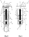
- Further aspects and advantages of the fastening tool, associated parts and a method of use thereof will become apparent from the ensuing description that is given by way of example only and with reference to the accompanying drawings in which:
- Fig. 1
- illustrates a fastening device in a side-view from a first side,
- Fig. 2
- illustrates the fastening device of
Fig. 1 in a side-view from a second side perpendicular to the first side, - Fig. 3
- illustrates the fastening device of
Fig. 1 in a side-view from a third side opposite to the first side, - Fig. 4
- illustrates the fastening device of
Fig. 1 in a side-view from the third side after fastening, - Fig. 5
- illustrates a fastening device at the beginning of fastening an object to a substructure,
- Fig. 6
- illustrates the fastening device of
Fig. 5 during fastening the object to the substructure, - Fig. 7
- illustrates the fastening device of
Fig. 5 during fastening the object to the substructure, and - Fig. 8
- illustrates the fastening device of
Fig. 5 after fastening the object to the substructure. -
Figs. 1, 2 ,3, and 4 show afastening device 10 for fastening anobject 1 to asubstructure 5 in afastening direction 11. As shown inFig. 4 , theobject 1 is a grating havingload bars 2 andcross bars 3. Thesubstructure 5 may be a T-shaped beam or similar construction element, e.g. of a building such as a powerplant. - The
fastening device 10 comprises aframe 20 comprising amain plate 21 and anupper plate 22 each of which is made of a sheet metal part and has a generally U-shaped cross section. Thefastening device 10 further comprises aholder 30 having two abutment faces 31 for abutting upon theobject 1 in thefastening direction 11. Theholder 30 comprises twohooks 32 each provided for clasping theobject 1, particularly one of theload bars 2, respectively, as shown inFig. 4 . Each of thehooks 32 is made of a sheet metal part and has a U-shaped cross section. Theholder 30, particularly each of thehooks 32, and theframe 20, particularly themain plate 21, are rigidly connected to each other and preferably together form one single element. In a non-shown embodiment, the holder and the upper plate are rigidly connected to each other or together form one single element. - The
fastening device 10 further comprises a threadedspindle 40 mounted to theframe 20. Thespindle 40 comprises ashaft 42 having a thread and defining aspindle axis 41 which is oriented in parallel to thefastening direction 11. In an upper end region of theshaft 42, thespindle 40 comprises anupper head 43. Theupper head 43 and theshaft 42 together form one single element. Theupper head 43 may comprise a screw drive, such as a Phillips, external or internal Hex, Torx or similar drive, enabling rotatingly driving thespindle 40. In a lower end region of theshaft 42, thespindle 40 comprises alower head 44. Thelower head 44 comprises a cap nut screwed on the lower end region of theshaft 42. - The
frame 20, particularly theupper plate 22, comprises anupper bearing 23 which may be formed as a hole in theupper plate 22. Further, theframe 20, particularly themain plate 21, comprises alower bearing 24 which may be formed as a hole in themain plate 21. Thespindle 40 is held in position with respect to theframe 20 by the upper andlower bearings upper head 43 bears against theupper bearing 23 in thefastening direction 11 and thelower head 44 bears against thelower bearing 24 in a direction opposite to thefastening direction 11. In this arrangement, themain plate 21 and theupper plate 22 are held together by thespindle 40. Aspring washer 45 arranged between theupper head 43 and theupper bearing 23 pre-tensions theupper plate 22 against themain plate 21, thereby preventing themain plate 21,upper plate 22 and/orspindle 40 from loose movement with respect to each other. - The
fastening device 10 further comprises aspindle nut 50 which has an inner thread (not shown) and which is screwed on thespindle 40. Rotating thespindle 40 about thespindle axis 41 causes thespindle nut 50 to linearly move along thespindle axis 41. To this end, theframe 20 comprises aguide 25 for guiding thespindle nut 50 along thespindle axis 41 during rotation of thespindle 40 about thespindle axis 41. Theguide 25 comprises twoguide channels 26 each formed as a slot which is oriented in parallel to thespindle axis 41. Thespindle nut 50 has a longitudinal shape and engages theguide channels 26 such that thespindle nut 50 is prevented from rotating about thespindle axis 41 during its movement along thespindle axis 41. - The
fastening device 10 further comprises acounterholder 60 which is hinged to thespindle nut 50. To this end, thespindle nut 50 has a cylindrical shape and thecounterholder 60 has abore 61 receiving thespindle nut 50. Thecounterholder 60 comprises afirst arm 70 pointing from thespindle nut 50 in a first-arm direction 71. Thefirst arm 70 has a firstcounter-abutment face 72 for abutting upon thesubstructure 5 in a direction opposite to thefastening direction 11. The firstcounter-abutment face 72 is serrated to reduce slipping between thefirst arm 70 and thesubstructure 5. Further, thecounterholder 60 comprises asecond arm 80 pointing from thespindle nut 50 in a second-arm direction 81 and comprising anarm element 83 and asupport element 84 carried by thearm element 83. - With respect to the
arm element 83, thesupport element 84 is movable between an inactive position (shown inFig. 3 ) and an active position (shown inFig. 4 ). In the active position, thesupport element 84 extends through an opening provided at thearm element 83. Thesupport element 84 is spring-biased into its active position and provides the corresponding spring force by its form as a spring clip. However, if thecounterholder 60 is in the position shown inFigs. 1, 2 ,3 , theframe 20 forces thesupport element 84 into its inactive position. When thecounterholder 60 pivots into the position shown inFig. 4 , thesupport element 84 is released and quickly moves into its active position, in a direction which is inclined, or perpendicular with respect to the second-arm direction 81, thespindle axis 41, and thefastening direction 11. Thesecond arm 80, particularly thesupport element 84, has a secondcounter-abutment face 82 for abutting upon theobject 1 in a direction opposite to thefastening direction 11 when thesupport element 84 is in its active position. In the active position of thesupport element 84, the secondcounter-abutment face 82 protrudes behind thearm element 83 and theframe 20. - The second-
arm direction 81 is opposite to the first-arm direction 71. Thefirst arm 70 and thearm element 83 of thesecond arm 80 are rigidly connected to each other and form one single element which is made of a sheet metal part and has a U-shaped cross section opening downwards in the position shown inFig. 4 . Further, thecounterholder 60 is provided with arecess 61 formed as a slot and providing a clearance for thespindle 40 when thecounterholder 60 pivots about thespindle nut 50. Theframe 20, by its U-shaped cross section, forms a passage providing a clearance for thecounterholder 60 during its pivoting about thespindle nut 50. -
Fig. 5, 6 ,7, and 8 show thefastening device 10 during fastening theobject 1 to thesubstructure 5. In a first step (Fig. 5 ), thefastening device 10 is inserted in a straight movement into an opening of theobject 1, until theholder 30 abuts upon one or two of the load bars 2 of the object 1 (Fig. 6 ). In a subsequent step (Fig. 7 ), thecounterholder 60 pivots about thespindle nut 50 from a mounting position (shown inFigs. 1, 2 ,3 ,5, 6 ) in which the first-arm direction 71 is substantially parallel to thespindle axis 41, to a fastening position (shown inFigs. 4 ,7, 8 ) in which the first-arm direction 71 is substantially perpendicular to thespindle axis 41. In a final step, thespindle 40 is rotated so as to move thespindle nut 50 upwards until the firstcounter-abutment face 72 abuts thesubstructure 5 and the secondcounter-abutment face 82 abuts one of the load bars 2 of theobject 1. - When the
counterholder 60 is in the mounting position, easy insertion of the fastening device in the opening of theobject 1 is enabled. When thecounterholder 60 is in the fastening position, safe engagement behind thesubstructure 5 by thefastening device 10 is provided. In this way, thefastening device 10 is easily and safely installed from one side of theobject 1. - The foregoing description of exemplary embodiments of the invention have been presented for purposes of illustration and of description. It is not intended to be exhaustive or to limit the invention to the precise form disclosed, and modifications and variations are possible in light of the above teachings or may be acquired from practice of the invention. The functionality described may be distributed among modules that differ in number and distribution of functionality from those described herein. Additionally, the order of execution of the functions may be changed depending on the embodiment. The embodiments were chosen and described in order to explain the principles of the invention and as practical applications of the invention to enable one skilled in the art to utilize the invention in various embodiments and with various modifications as suited to the particular use contemplated. It is intended that the scope of the invention be defined by the claims appended hereto and their equivalents.
Claims (15)
- A fastening device for fastening an object to a substructure in a fastening direction, comprising a frame, a threaded spindle rotatably mounted to the frame and having a spindle axis, a spindle nut screwed on the spindle and linearly movable along the spindle axis by rotating the spindle about the spindle axis, a holder having an abutment face for abutting upon the object in the fastening direction, and a counterholder hinged to the spindle nut and comprising a first arm pointing from the spindle nut in a first-arm direction and having a first counter-abutment face for abutting upon the substructure in a direction opposite to the fastening direction.
- A fastening device according to claim 1, wherein the counterholder comprises a second arm pointing from the spindle nut in a second-arm direction and having a second counter-abutment face for abutting upon the object in a direction opposite to the fastening direction.
- A fastening device according to claim 2, wherein the second-arm direction is substantially opposite to the first-arm direction.
- A fastening device according to any of claims 2 and 3, wherein the first and second arms are rigidly connected to each other.
- A fastening device according to any of the preceding claims, wherein the counterholder is pivotable about the spindle nut between a mounting position and a fastening position, wherein in the mounting position, the first-arm direction is substantially parallel to the spindle axis, and wherein in the fastening position, the first-arm direction is substantially perpendicular to the spindle axis.
- A fastening device according to any of the preceding claims, wherein the counterholder comprises a recess providing a clearance for the spindle during pivoting by the counterholder about the spindle nut.
- A fastening device according to any of the preceding claims, wherein the frame comprises a passage providing a clearance for the counterholder during pivoting by the counterholder about the spindle nut.
- A fastening device according to any of the preceding claims, wherein the frame comprises a guide for guiding the spindle nut along the spindle axis during rotation of the spindle about the spindle axis.
- A fastening device according to claim 8, wherein the guide comprises a guide channel, and wherein the spindle nut engages the guide channel during its movement along the spindle axis.
- A fastening device according to any of the preceding claims, wherein the frame comprises an upper bearing and a lower bearing, and wherein the spindle is held in position with respect to the frame by the upper and lower bearings.
- A fastening device according to claim 10, wherein the spindle comprises an upper head bearing against the upper bearing in the fastening direction.
- A fastening device according to any of claims 10 and 11, wherein the spindle comprises a lower head bearing against the lower bearing in a direction opposite to the fastening direction.
- A fastening device according to any of the preceding claims, wherein the holder comprises a hook for clasping the object.
- A fastening device according to any of the preceding claims, wherein at least one of the frame, the holder and the counterholder comprises a sheet metal part.
- A fastening device according to any of the preceding claims, wherein at least one of the frame, the holder and the counterholder has a U-shaped cross section.
Priority Applications (3)
| Application Number | Priority Date | Filing Date | Title |
|---|---|---|---|
| EP20175637.6A EP3913236A1 (en) | 2020-05-20 | 2020-05-20 | Fastening device |
| PCT/EP2020/086927 WO2021123095A1 (en) | 2019-12-20 | 2020-12-18 | Fastening device |
| TW109145039A TW202124852A (en) | 2019-12-20 | 2020-12-18 | Fastening device |
Applications Claiming Priority (1)
| Application Number | Priority Date | Filing Date | Title |
|---|---|---|---|
| EP20175637.6A EP3913236A1 (en) | 2020-05-20 | 2020-05-20 | Fastening device |
Publications (1)
| Publication Number | Publication Date |
|---|---|
| EP3913236A1 true EP3913236A1 (en) | 2021-11-24 |
Family
ID=70779613
Family Applications (1)
| Application Number | Title | Priority Date | Filing Date |
|---|---|---|---|
| EP20175637.6A Withdrawn EP3913236A1 (en) | 2019-12-20 | 2020-05-20 | Fastening device |
Country Status (1)
| Country | Link |
|---|---|
| EP (1) | EP3913236A1 (en) |
Cited By (1)
| Publication number | Priority date | Publication date | Assignee | Title |
|---|---|---|---|---|
| WO2025093188A1 (en) * | 2023-11-01 | 2025-05-08 | MÜPRO Services GmbH | Device for releasably fastening a base plate to a mounting rail and system for installing a base plate on a mounting rail |
Citations (5)
| Publication number | Priority date | Publication date | Assignee | Title |
|---|---|---|---|---|
| US1694494A (en) * | 1925-06-19 | 1928-12-11 | John Edward Ogden | Toggle bolt |
| US4116104A (en) * | 1977-04-15 | 1978-09-26 | Arvest Gethner Kennedy | Toggle bolt wing nut retainer |
| FR2542044A1 (en) * | 1983-03-02 | 1984-09-07 | Robveille Alain | Fastening walkways to a section |
| US20050129482A1 (en) * | 2003-12-16 | 2005-06-16 | Wang San S. | Retention device |
| DE202013102220U1 (en) * | 2013-05-22 | 2013-06-06 | CSF Wunderle GmbH | Holding device for license plate and kit comprising such a holding device |
-
2020
- 2020-05-20 EP EP20175637.6A patent/EP3913236A1/en not_active Withdrawn
Patent Citations (5)
| Publication number | Priority date | Publication date | Assignee | Title |
|---|---|---|---|---|
| US1694494A (en) * | 1925-06-19 | 1928-12-11 | John Edward Ogden | Toggle bolt |
| US4116104A (en) * | 1977-04-15 | 1978-09-26 | Arvest Gethner Kennedy | Toggle bolt wing nut retainer |
| FR2542044A1 (en) * | 1983-03-02 | 1984-09-07 | Robveille Alain | Fastening walkways to a section |
| US20050129482A1 (en) * | 2003-12-16 | 2005-06-16 | Wang San S. | Retention device |
| DE202013102220U1 (en) * | 2013-05-22 | 2013-06-06 | CSF Wunderle GmbH | Holding device for license plate and kit comprising such a holding device |
Cited By (1)
| Publication number | Priority date | Publication date | Assignee | Title |
|---|---|---|---|---|
| WO2025093188A1 (en) * | 2023-11-01 | 2025-05-08 | MÜPRO Services GmbH | Device for releasably fastening a base plate to a mounting rail and system for installing a base plate on a mounting rail |
Similar Documents
| Publication | Publication Date | Title |
|---|---|---|
| JP3440102B2 (en) | Screw fastener assembly | |
| US5941654A (en) | Bus bar assembly, fastening system therefor, and method | |
| JP6490362B2 (en) | Fastening system with eccentric ring | |
| US9039377B2 (en) | Fan assemblies and methods for assembling same | |
| EP3557209A1 (en) | Pulling device | |
| US20040136802A1 (en) | Expansion bolt | |
| CN2200720Y (en) | Double-locking anti-loose combined nut | |
| WO2021123095A1 (en) | Fastening device | |
| CA2158980A1 (en) | Fastening system | |
| KR100355166B1 (en) | Insert Nuts & Fasteners | |
| US2850934A (en) | Two headed bolt having predetermined shear strength | |
| JP2581518B2 (en) | Spacer washer for bolt joint | |
| US20090047094A1 (en) | Tolerance compensating fastener | |
| US8302282B2 (en) | System and/or assembly for installing fastening devices and method of installing fastening devices using the system or assembly | |
| CZ297000B6 (en) | Retaining element for cap screws | |
| JP2016223620A (en) | Anchor bolt | |
| JP2000220623A (en) | Fixing structure for nut | |
| US20050000327A1 (en) | Adjustable socket | |
| US20070031207A1 (en) | Lockwire header bolts | |
| RU2154203C1 (en) | Bolt for mounting in dead opening | |
| JP4198061B2 (en) | Fixing device and method for attaching an object to a support structure | |
| US10495133B2 (en) | Captive bolt and retainer | |
| US20180340650A1 (en) | Installation device | |
| US5516247A (en) | Fastening device | |
| EP3913235A1 (en) | Fastening device |
Legal Events
| Date | Code | Title | Description |
|---|---|---|---|
| PUAI | Public reference made under article 153(3) epc to a published international application that has entered the european phase |
Free format text: ORIGINAL CODE: 0009012 |
|
| STAA | Information on the status of an ep patent application or granted ep patent |
Free format text: STATUS: THE APPLICATION HAS BEEN PUBLISHED |
|
| AK | Designated contracting states |
Kind code of ref document: A1 Designated state(s): AL AT BE BG CH CY CZ DE DK EE ES FI FR GB GR HR HU IE IS IT LI LT LU LV MC MK MT NL NO PL PT RO RS SE SI SK SM TR |
|
| B565 | Issuance of search results under rule 164(2) epc |
Effective date: 20201113 |
|
| STAA | Information on the status of an ep patent application or granted ep patent |
Free format text: STATUS: THE APPLICATION IS DEEMED TO BE WITHDRAWN |
|
| 18D | Application deemed to be withdrawn |
Effective date: 20220525 |