EP3913221A1 - Air conditioner and preheating operation method - Google Patents
Air conditioner and preheating operation method Download PDFInfo
- Publication number
- EP3913221A1 EP3913221A1 EP19910291.4A EP19910291A EP3913221A1 EP 3913221 A1 EP3913221 A1 EP 3913221A1 EP 19910291 A EP19910291 A EP 19910291A EP 3913221 A1 EP3913221 A1 EP 3913221A1
- Authority
- EP
- European Patent Office
- Prior art keywords
- preheating
- path
- switch
- compressor
- power
- Prior art date
- Legal status (The legal status is an assumption and is not a legal conclusion. Google has not performed a legal analysis and makes no representation as to the accuracy of the status listed.)
- Withdrawn
Links
- 238000000034 method Methods 0.000 title claims description 13
- 239000003990 capacitor Substances 0.000 claims abstract description 41
- 238000009499 grossing Methods 0.000 claims abstract description 41
- 230000005611 electricity Effects 0.000 claims abstract description 5
- 230000001629 suppression Effects 0.000 description 5
- 238000010586 diagram Methods 0.000 description 4
- 238000004378 air conditioning Methods 0.000 description 3
- 238000006243 chemical reaction Methods 0.000 description 3
- 239000003507 refrigerant Substances 0.000 description 3
- 230000007423 decrease Effects 0.000 description 2
- 230000000694 effects Effects 0.000 description 2
- 230000003252 repetitive effect Effects 0.000 description 2
- 239000004065 semiconductor Substances 0.000 description 2
- 238000000926 separation method Methods 0.000 description 2
- 230000002159 abnormal effect Effects 0.000 description 1
- 230000005856 abnormality Effects 0.000 description 1
- 230000006866 deterioration Effects 0.000 description 1
- 230000005284 excitation Effects 0.000 description 1
- 238000010438 heat treatment Methods 0.000 description 1
- 230000006698 induction Effects 0.000 description 1
- 238000004353 relayed correlation spectroscopy Methods 0.000 description 1
Images


Classifications
-
- H—ELECTRICITY
- H02—GENERATION; CONVERSION OR DISTRIBUTION OF ELECTRIC POWER
- H02M—APPARATUS FOR CONVERSION BETWEEN AC AND AC, BETWEEN AC AND DC, OR BETWEEN DC AND DC, AND FOR USE WITH MAINS OR SIMILAR POWER SUPPLY SYSTEMS; CONVERSION OF DC OR AC INPUT POWER INTO SURGE OUTPUT POWER; CONTROL OR REGULATION THEREOF
- H02M1/00—Details of apparatus for conversion
- H02M1/36—Means for starting or stopping converters
-
- F—MECHANICAL ENGINEERING; LIGHTING; HEATING; WEAPONS; BLASTING
- F25—REFRIGERATION OR COOLING; COMBINED HEATING AND REFRIGERATION SYSTEMS; HEAT PUMP SYSTEMS; MANUFACTURE OR STORAGE OF ICE; LIQUEFACTION SOLIDIFICATION OF GASES
- F25B—REFRIGERATION MACHINES, PLANTS OR SYSTEMS; COMBINED HEATING AND REFRIGERATION SYSTEMS; HEAT PUMP SYSTEMS
- F25B49/00—Arrangement or mounting of control or safety devices
- F25B49/02—Arrangement or mounting of control or safety devices for compression type machines, plants or systems
- F25B49/022—Compressor control arrangements
-
- F—MECHANICAL ENGINEERING; LIGHTING; HEATING; WEAPONS; BLASTING
- F04—POSITIVE - DISPLACEMENT MACHINES FOR LIQUIDS; PUMPS FOR LIQUIDS OR ELASTIC FLUIDS
- F04B—POSITIVE-DISPLACEMENT MACHINES FOR LIQUIDS; PUMPS
- F04B39/00—Component parts, details, or accessories, of pumps or pumping systems specially adapted for elastic fluids, not otherwise provided for in, or of interest apart from, groups F04B25/00 - F04B37/00
- F04B39/06—Cooling; Heating; Prevention of freezing
-
- F—MECHANICAL ENGINEERING; LIGHTING; HEATING; WEAPONS; BLASTING
- F24—HEATING; RANGES; VENTILATING
- F24F—AIR-CONDITIONING; AIR-HUMIDIFICATION; VENTILATION; USE OF AIR CURRENTS FOR SCREENING
- F24F11/00—Control or safety arrangements
- F24F11/70—Control systems characterised by their outputs; Constructional details thereof
- F24F11/80—Control systems characterised by their outputs; Constructional details thereof for controlling the temperature of the supplied air
- F24F11/86—Control systems characterised by their outputs; Constructional details thereof for controlling the temperature of the supplied air by controlling compressors within refrigeration or heat pump circuits
-
- F—MECHANICAL ENGINEERING; LIGHTING; HEATING; WEAPONS; BLASTING
- F25—REFRIGERATION OR COOLING; COMBINED HEATING AND REFRIGERATION SYSTEMS; HEAT PUMP SYSTEMS; MANUFACTURE OR STORAGE OF ICE; LIQUEFACTION SOLIDIFICATION OF GASES
- F25B—REFRIGERATION MACHINES, PLANTS OR SYSTEMS; COMBINED HEATING AND REFRIGERATION SYSTEMS; HEAT PUMP SYSTEMS
- F25B31/00—Compressor arrangements
- F25B31/02—Compressor arrangements of motor-compressor units
- F25B31/026—Compressor arrangements of motor-compressor units with compressor of rotary type
-
- F—MECHANICAL ENGINEERING; LIGHTING; HEATING; WEAPONS; BLASTING
- F04—POSITIVE - DISPLACEMENT MACHINES FOR LIQUIDS; PUMPS FOR LIQUIDS OR ELASTIC FLUIDS
- F04B—POSITIVE-DISPLACEMENT MACHINES FOR LIQUIDS; PUMPS
- F04B35/00—Piston pumps specially adapted for elastic fluids and characterised by the driving means to their working members, or by combination with, or adaptation to, specific driving engines or motors, not otherwise provided for
- F04B35/04—Piston pumps specially adapted for elastic fluids and characterised by the driving means to their working members, or by combination with, or adaptation to, specific driving engines or motors, not otherwise provided for the means being electric
-
- F—MECHANICAL ENGINEERING; LIGHTING; HEATING; WEAPONS; BLASTING
- F04—POSITIVE - DISPLACEMENT MACHINES FOR LIQUIDS; PUMPS FOR LIQUIDS OR ELASTIC FLUIDS
- F04B—POSITIVE-DISPLACEMENT MACHINES FOR LIQUIDS; PUMPS
- F04B49/00—Control, e.g. of pump delivery, or pump pressure of, or safety measures for, machines, pumps, or pumping installations, not otherwise provided for, or of interest apart from, groups F04B1/00 - F04B47/00
- F04B49/06—Control using electricity
- F04B49/065—Control using electricity and making use of computers
-
- F—MECHANICAL ENGINEERING; LIGHTING; HEATING; WEAPONS; BLASTING
- F24—HEATING; RANGES; VENTILATING
- F24F—AIR-CONDITIONING; AIR-HUMIDIFICATION; VENTILATION; USE OF AIR CURRENTS FOR SCREENING
- F24F11/00—Control or safety arrangements
- F24F11/88—Electrical aspects, e.g. circuits
-
- H—ELECTRICITY
- H02—GENERATION; CONVERSION OR DISTRIBUTION OF ELECTRIC POWER
- H02M—APPARATUS FOR CONVERSION BETWEEN AC AND AC, BETWEEN AC AND DC, OR BETWEEN DC AND DC, AND FOR USE WITH MAINS OR SIMILAR POWER SUPPLY SYSTEMS; CONVERSION OF DC OR AC INPUT POWER INTO SURGE OUTPUT POWER; CONTROL OR REGULATION THEREOF
- H02M1/00—Details of apparatus for conversion
- H02M1/32—Means for protecting converters other than automatic disconnection
- H02M1/327—Means for protecting converters other than automatic disconnection against abnormal temperatures
-
- H—ELECTRICITY
- H02—GENERATION; CONVERSION OR DISTRIBUTION OF ELECTRIC POWER
- H02M—APPARATUS FOR CONVERSION BETWEEN AC AND AC, BETWEEN AC AND DC, OR BETWEEN DC AND DC, AND FOR USE WITH MAINS OR SIMILAR POWER SUPPLY SYSTEMS; CONVERSION OF DC OR AC INPUT POWER INTO SURGE OUTPUT POWER; CONTROL OR REGULATION THEREOF
- H02M5/00—Conversion of AC power input into AC power output, e.g. for change of voltage, for change of frequency, for change of number of phases
- H02M5/40—Conversion of AC power input into AC power output, e.g. for change of voltage, for change of frequency, for change of number of phases with intermediate conversion into DC
- H02M5/42—Conversion of AC power input into AC power output, e.g. for change of voltage, for change of frequency, for change of number of phases with intermediate conversion into DC by static converters
- H02M5/44—Conversion of AC power input into AC power output, e.g. for change of voltage, for change of frequency, for change of number of phases with intermediate conversion into DC by static converters using discharge tubes or semiconductor devices to convert the intermediate DC into AC
- H02M5/453—Conversion of AC power input into AC power output, e.g. for change of voltage, for change of frequency, for change of number of phases with intermediate conversion into DC by static converters using discharge tubes or semiconductor devices to convert the intermediate DC into AC using devices of a triode or transistor type requiring continuous application of a control signal
- H02M5/458—Conversion of AC power input into AC power output, e.g. for change of voltage, for change of frequency, for change of number of phases with intermediate conversion into DC by static converters using discharge tubes or semiconductor devices to convert the intermediate DC into AC using devices of a triode or transistor type requiring continuous application of a control signal using semiconductor devices only
Definitions
- the present disclosure relates to an air conditioner and a preheating operation method to be used in an environment that requires preheating of a compressor.
- a compressor is preheated in accordance with a temperature, by operating an inverter for a drive circuit configured to drive the compressor for the purpose of preheating, and feeding a current so as not to rotate a motor of the compressor (refer to, for example, Patent Literature 1).
- FIG. 1 is a simplified diagram showing only main circuit elements of a drive circuit for a compressor to be mounted in an air conditioner (an outdoor unit).
- a main circuit relay 202 is disposed on an AC path between an AC power source 201 and a rectifier 203.
- a DC reactor 204 and a smoothing capacitor 205 are connected to a DC path on a DC output side of the rectifier 203.
- An inverter 208 assembled into a module as an intelligent power module (IPM) is connected to the DC path.
- a compressor 209 is connected to the inverter 208.
- a voltage at the DC path is divided by shunt resistors 206 and 207, and then is applied as a DC voltage to a controller (not illustrated).
- the main circuit relay 202 is closed during a normal air conditioning operation of the compressor 209.
- the inverter 208 outputs three-phase AC power to rotate the compressor 209.
- the main circuit relay 202 is closed, and the inverter 208 feeds a current to, for example, two of three-phase coils to perform a switching operation that achieves an open-phase operation.
- the compressor 209 does not rotate, but generates heat by supplying the coils therein with electricity.
- the compressor 209 is thus preheated.
- the main circuit relay 202 remains closed during the preheating operation.
- power that contributes to preheating of the compressor 209 is, for example, 40 W
- power to be consumed by the drive circuit that is, power which the AC power source 201 supplies is, for example, 70 to 80 W higher than the power that contributes to preheating of the compressor 209.
- Patent Literature 1 Japanese Unexamined Patent Publication No. 2000-205627
- An object of the present disclosure is to reduce power to be supplied for preheating.
- the preheating operation method enables reduction in power loss for preheating.
- FIG. 2 is a circuit diagram of an exemplary drive circuit 50 for a compressor 2 in an air conditioner (an outdoor unit) 100.
- the drive circuit 50 is mounted on one printed circuit board.
- a main circuit switch 5 is disposed on one of two AC paths 3 led from an AC power source 1.
- a bypass circuit 6 is connected to the main circuit switch 5 in parallel.
- the bypass circuit 6 includes a preheating switch 7 and a current suppressing element 8 connected in series.
- the current suppressing element 8 suppresses an inrush current when the preheating switch 7 is closed. Suppressing the inrush current retards deterioration in the preheating switch 7 and increases the durable number of switching operations.
- Each of the main circuit switch 5 and the preheating switch 7 may be an excitation mechanical contact relay.
- Each of the main circuit switch 5 and the preheating switch 7 may alternatively be a semiconductor relay or a semiconductor switch element.
- the current suppressing element 8 is resistor or a negative temperature coefficient (NTC) thermistor. In the NTC thermistor, a resistance value decreases as a temperature increases due to energization.
- a full-bridge rectifier 4 is connected to the AC paths 3.
- a DC reactor 11 is disposed on one of two DC paths 9 from a DC output end of the rectifier 4 to an inverter 10 (a DC link).
- the inverter 10 is assembled into a module as an intelligent power module (IPM).
- IPM intelligent power module
- a smoothing capacitor 12 and two shunt resistors 13 and 14 connected in series are disposed closer to the inverter 10 than the DC reactor 11 is, and are connected between the two DC paths 9.
- the controller 15 includes a central processing unit (CPU) and a memory, and achieves required control by executing a program recorded in the memory.
- CPU central processing unit
- the controller 15 receives an output signal from a temperature sensor 17 that detects a temperature near the compressor 2.
- the controller 15 opens and closes each of the main circuit switch 5 and the preheating switch 7.
- the inverter 10 is provided with a dedicated controller 16.
- the inverter 10 performs a switching operation, based on a command from the controller 16.
- the controller 16 includes a CPU and a memory, and achieves required control by executing a program recorded in the memory.
- the controllers 15 and 16 may exchange control information with each other.
- the controllers 15 and 16 may be combined into one controller.
- the main circuit switch 5 is closed, while the preheating switch 7 is opened during a normal air conditioning operation.
- the inverter 10 performs the switching operation in accordance with a command from the controller 16, and drives the compressor 2 to rotate the compressor 2.
- the rectifier 4 causes a power loss upon AC/DC conversion.
- the DC reactor 11 also causes a power loss due to energization. The same applies to the current suppressing element 8. In a preheating operation to be described below, control is performed in consideration of the power losses.
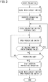
- FIG. 3 is a flowchart of an exemplary procedure of the preheating operation.
- the controller 15 carries out the flowchart.
- the controller 16 also carries out the flowchart in cooperation with the controller 15 as required, in accordance with a command from the controller 15.
- the preheating operation is performed when a temperature detected by the temperature sensor 17 is equal to or less than a predetermined temperature in a state in which the air conditioner 100 stops the air conditioning operation.
- the controller 15 may terminate the preheating when the temperature detected by the temperature sensor 17 exceeds the predetermined temperature, or may terminate the preheating after a lapse of a certain time from the start of the preheating operation.
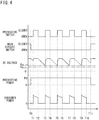
- FIG. 4 is a time chart of, for example, an operation, a voltage, and power as to the components during the preheating operation.
- the horizontal axis represents a time.
- FIG. 4 illustrates, from above, open and closed states of the preheating switch 7 ("closed”: H level, "open”: L level), open and closed states of the main circuit switch 5, a DC voltage at the DC paths 9, preheating power supplied to the compressor 2, and consumed power by the drive circuit 50.
- the controller 15 opens the main circuit switch 5 (step S1).
- the main circuit switch 5 is open throughout the preheating operation.
- a time T0 corresponds to the time when the controller 15 opens the main circuit switch 5.
- the preheating switch 7 is also open.
- the controller 15 issues a command to the controller 16, so that the controller 16 causes the inverter 10 to operate for the preheating operation (step S2).
- the operation for the preheating operation, which the inverter 10 performs, is, for example, an open-phase operation for the compressor 2.
- a current is fed to two of the three-phase motor coils in the compressor 2 so as not to generate a rotating magnetic field.
- the motor coils, through which the current has flowed, generate heat to preheat the compressor 2. This preheating allows separation of a refrigerant dissolved in an oil from the oil.
- induction heating also enables the preheating operation.
- a high-frequency current is fed to two of the three-phase motor coils in the compressor 2 so as not to cause a rotating magnetic field.
- the motor coils, through which the high-frequency current flows, generate heat to preheat the compressor 2. This preheating allows separation of the refrigerant dissolved in the oil from the oil.
- preheating power P0 is supplied to the inverter 10 by a discharge from the smoothing capacitor 12 ( FIG. 4 ).
- the AC power source 1 supplies no power, the DC voltage starts to drop due to the discharge from the smoothing capacitor 12 (immediately after the time T0 in FIG. 4 ).
- the controller 15 closes the preheating switch 7 for a certain time from a time T1 to a time T2 (step S3).
- the certain time is a time sufficient for bringing the smoothing capacitor 12 into a fully charged state.
- the controller 15 opens the preheating switch 7 at the time T2 (step S4).
- the controller 15 opens the preheating switch 7 to interrupt the power supply from the AC paths 3, but maintains supply of the preheating power to the inverter 10 by the discharge from the smoothing capacitor 12.
- the DC voltage drops due to the discharge from the smoothing capacitor 12.
- the controller 15 repeatedly carries out steps S4, S5, and S6 until the DC voltage drops to a predetermined voltage threshold value V DC_th1 (step S5), unless the preheating ends (step S6).
- the voltage threshold value V DC_th1 is slightly larger than an undervoltage abnormality threshold value V DC_th so as not to decrease to a level recognized abnormal as a shortage of the DC voltage.
- step S5 when the DC voltage drops to the predetermined value V DC_th1 ("YES" in step S5), the controller 15 closes the preheating switch 7 for a certain time from the time T3 to a time T4 (step S3). This certain time is equal to the foregoing time from the time T1 to the time T2.
- the controller 15 opens the preheating switch 7 (times T4 to T5, times T6 to T7, times T8 to T9) and closes the preheating switch 7 (times T5 to T6, times T7 to T8, times T9 to T10) repeatedly in a manner similar to that described above.
- the controllers 15 and 16 stop the preheating operation for the inverter 10 (step S7).
- the controller 15 closes the main circuit switch 5, and opens the preheating switch 7 or maintains the open state of the preheating switch 7 (step S8).
- the preheating operation then ends at a time T11.
- the consumed power by the drive circuit 50 (the power supplied from the AC power source 1 through the AC paths 3) is zero during the period that the preheating switch 7 is open. This is because the preheating power is supplied to the inverter 10 by the discharge from the smoothing capacitor 12 during the period that the preheating switch 7 is open. Accordingly, no power loss occurs at the DC reactor 11, the rectifier 4, and the current suppressing element 8 during the period that the preheating switch 7 is open. As to the entire preheating operation period, a power loss is suppressed by a period during which no power loss occurs.
- air conditioners for home use There are air conditioners for home use and air conditioners for business use.
- the air conditioners for business use are higher in power for a preheating operation than the air conditioners for home use, and tend to cause a higher power loss not contributing to preheating. For this reason, suppressing a power loss during a preheating operation increases a power loss reduction effect particularly in air conditioners for business use.
- the preheating switch 7 in the bypass circuit 6 for the main circuit switch 5 is used as a switch to be opened and closed during a preheating operation.
- the DC reactor 11 also produces an inrush current suppression effect to a certain degree. Therefore, a switch to be opened and closed during the preheating operation is not limited to the preheating switch 7.
- an effect similar to that described above is also produced in such a manner that the main circuit switch 5 is opened and closed during the preheating operation.
- a switch to be opened and closed during the preheating operation may be disposed between the rectifier 4 and the DC reactor 11. In short, it is necessary to provide a switch on an electric path from the AC paths 3 to the smoothing capacitor 12.
- the switch e.g., the preheating switch 7
- the controller 15 closes and opens the switch during the preheating operation of supplying electricity for preheating the compressor 2 via the inverter 10.
- a source of directly supplying power for preheating differs between the case where the switch is closed and the case where the switch is open.
- the smoothing capacitor 12 is charged with the power on the AC paths 3, the power being supplied to the smoothing capacitor 12 via the rectifier 4, and the compressor 2 is preheated with the power supplied to the DC path 9, the power being supplied to the compressor 2 via the inverter 10.
- the compressor 2 is preheated with the discharge power from the smoothing capacitor 12, the discharge power being supplied to the compressor 2 via the inverter 10.
- the DC reactor 11 is disposed on one of the DC paths 9.
- the AC paths 3, the rectifier 4, the DC reactor 11, and the smoothing capacitor 12 are arranged in this order from the AC paths 3 to the smoothing capacitor 12. With this configuration, no current flows through the rectifier 4 and the DC reactor 11 in the state in which the switch is open. This configuration therefore enables reduction in relatively large power loss at the DC reactor 11, in addition to reduction in power loss at the rectifier 4.
- the controller 15 repeatedly closes and opens the switch during the preheating operation. This configuration enables suppression in excessive voltage drop at the DC paths 9, periodical discharge from the smoothing capacitor 12, and reduction in power loss, through repetitive charge and discharge, even when the smoothing capacitor 12 has a relatively small capacity (e.g., several tens of microfarads).
- the switch is, for example, the preheating switch 7 constituting the bypass circuit 6 arranged in parallel with the main circuit switch 5 on one of the AC paths 3, and the controller 15 opens the main circuit switch 5 during the preheating operation.
- This configuration enables the preheating operation by opening and closing the preheating switch 7 with the main circuit switch 5 opened.
- the bypass circuit 6 includes the preheating switch 7 and the current suppressing element 8 connected in series. This configuration allows the current suppressing element 8 to reduce an inrush current at the moment of closing the preheating switch that is in the open state.
- the controller 15 closes the switch when a voltage at the DC paths 9 drops to the predetermined voltage threshold value. This configuration therefore enables suppression in voltage drop at the DC paths 9 to be lower than the voltage threshold value.
- the present disclosure also provides the preheating operation method using the drive circuit 50 configured to drive the compressor 2 in the air conditioner.
- the preheating operation method includes: the first period of supplying power from the AC paths 3 to the DC paths 9 on which the smoothing capacitor 12 is disposed, via the rectifier 4, and preheating the compressor 2 with the power from the AC paths 3, the power being supplied to the compressor 2 from the DC paths 9 via the inverter 10; and the second period of stopping power supply from the AC paths 3, and preheating the compressor 2 with discharge power from the smoothing capacitor 12, the discharge power being supplied to the compressor 2 via the inverter 10.
- a source of directly supplying power for preheating differs between the first period and the second period.
- the smoothing capacitor 12 is charged with the power on the AC paths 3, the power being supplied to the smoothing capacitor 12 via the rectifier 4, and the compressor 2 is preheated with the power supplied to the DC paths 9, the power being supplied to the compressor 2 via the inverter 10.
- the compressor 2 is preheated with the discharge power from the smoothing capacitor 12, the discharge power being supplied to the compressor 2 via the inverter 10.
- no current is fed from the AC paths 3 to the rectifier 4; therefore, the rectifier 4 causes no power loss upon at least AC/DC conversion.
- the second period enables reduction in power loss for preheating.
Landscapes
- Engineering & Computer Science (AREA)
- Mechanical Engineering (AREA)
- General Engineering & Computer Science (AREA)
- Physics & Mathematics (AREA)
- Thermal Sciences (AREA)
- Chemical & Material Sciences (AREA)
- Combustion & Propulsion (AREA)
- Power Engineering (AREA)
- Inverter Devices (AREA)
- Air Conditioning Control Device (AREA)
- Compressor (AREA)
Abstract
Description
- The present disclosure relates to an air conditioner and a preheating operation method to be used in an environment that requires preheating of a compressor.
- It is occasionally necessary for an air conditioner to be used in a cold region to heat an oil and a refrigerant in a compressor. In view of this, according to a known technique, a compressor is preheated in accordance with a temperature, by operating an inverter for a drive circuit configured to drive the compressor for the purpose of preheating, and feeding a current so as not to rotate a motor of the compressor (refer to, for example, Patent Literature 1).
-
FIG. 1 is a simplified diagram showing only main circuit elements of a drive circuit for a compressor to be mounted in an air conditioner (an outdoor unit). Amain circuit relay 202 is disposed on an AC path between anAC power source 201 and arectifier 203. ADC reactor 204 and asmoothing capacitor 205 are connected to a DC path on a DC output side of therectifier 203. Aninverter 208 assembled into a module as an intelligent power module (IPM) is connected to the DC path. Acompressor 209 is connected to theinverter 208. A voltage at the DC path is divided byshunt resistors - The
main circuit relay 202 is closed during a normal air conditioning operation of thecompressor 209. Theinverter 208 outputs three-phase AC power to rotate thecompressor 209. During a preheating operation, themain circuit relay 202 is closed, and theinverter 208 feeds a current to, for example, two of three-phase coils to perform a switching operation that achieves an open-phase operation. During the open-phase operation, thecompressor 209 does not rotate, but generates heat by supplying the coils therein with electricity. Thecompressor 209 is thus preheated. Themain circuit relay 202 remains closed during the preheating operation. If power that contributes to preheating of thecompressor 209 is, for example, 40 W, power to be consumed by the drive circuit, that is, power which theAC power source 201 supplies is, for example, 70 to 80 W higher than the power that contributes to preheating of thecompressor 209. - Patent Literature 1:
Japanese Unexamined Patent Publication No. 2000-205627 - As described above, a power loss not contributing to preheating occurs during a preheating operation.
- An object of the present disclosure is to reduce power to be supplied for preheating.
-
- (1) The present disclosure provides an air conditioner including a compressor and a drive circuit configured to drive the compressor. The drive circuit includes an AC path, a rectifier connected to the AC path, a DC path on an output side of the rectifier, a smoothing capacitor connected to the DC path, an inverter connected to the DC path, a switch disposed on an electric path from the AC path to the smoothing capacitor, and a controller configured to close and open the switch during a preheating operation of supplying electricity for preheating the compressor via the inverter.
With this configuration, the air conditioner enables reduction in power loss for preheating.
The following configurations (2) to (6) are accompanying or selective configurations. - (2) In the air conditioner, a DC reactor is disposed on the DC path, and the AC path, the rectifier, the DC reactor, and the smoothing capacitor are arranged in this order from the AC path to the smoothing capacitor.
This configuration enables reduction in relatively large power loss at the DC reactor, in addition to reduction in power loss at the rectifier. - (3) In the air conditioner, the controller repeatedly closes and opens the switch during the preheating operation.
This configuration enables suppression in excessive voltage drop at the DC path, periodical discharge from the smoothing capacitor, and reduction in power loss, through repetitive charge and discharge, even when the smoothing capacitor has a relatively small capacity (e.g., several tens of microfarads). - (4) In the air conditioner, the controller closes the switch when a voltage at the DC path drops to a predetermined voltage threshold value.
This configuration enables suppression in voltage drop at the DC path to be lower than the voltage threshold value. - (5) In the air conditioner, the switch includes a preheating switch constituting a bypass circuit arranged in parallel with a main circuit switch on the AC path, and the controller opens the main circuit switch during the preheating operation.
This configuration enables the preheating operation by opening and closing the preheating switch with the main circuit switch opened. - (6) In the air conditioner, the bypass circuit includes the preheating switch and a current suppressing element connected in series.
This configuration allows the current suppressing element to reduce an inrush current at the moment of closing the preheating switch that is in the open state. - (7) The present disclosure also provides a preheating operation method using a drive circuit configured to drive a compressor in an air conditioner. The preheating operation method includes: a first period of supplying power from an AC path to a DC path on which a smoothing capacitor is disposed, via a rectifier, and preheating the compressor with the power from the AC path, the power being supplied to the compressor from the DC path via an inverter; and a second period of stopping power supply from the AC path, and preheating the compressor with discharge power from the smoothing capacitor, the discharge power being supplied to the compressor via the inverter.
- With this configuration, the preheating operation method enables reduction in power loss for preheating.
-
-
FIG. 1 is a simplified diagram showing only main circuit elements of a drive circuit for a compressor to be mounted in a conventional air conditioner. -
FIG. 2 is a circuit diagram of an exemplary drive circuit for a compressor in an air conditioner (an outdoor unit). -
FIG. 3 is a flowchart of an exemplary procedure of a preheating operation. -
FIG. 4 is a time chart of, for example, an operation, a voltage, and power as to components during a preheating operation. - An embodiment will be described below.
-
FIG. 2 is a circuit diagram of anexemplary drive circuit 50 for acompressor 2 in an air conditioner (an outdoor unit) 100. For example, thedrive circuit 50 is mounted on one printed circuit board. Amain circuit switch 5 is disposed on one of twoAC paths 3 led from anAC power source 1. Abypass circuit 6 is connected to themain circuit switch 5 in parallel. Thebypass circuit 6 includes a preheating switch 7 and a current suppressing element 8 connected in series. The current suppressing element 8 suppresses an inrush current when the preheating switch 7 is closed. Suppressing the inrush current retards deterioration in the preheating switch 7 and increases the durable number of switching operations. - Each of the
main circuit switch 5 and the preheating switch 7 may be an excitation mechanical contact relay. Each of themain circuit switch 5 and the preheating switch 7 may alternatively be a semiconductor relay or a semiconductor switch element. The current suppressing element 8 is resistor or a negative temperature coefficient (NTC) thermistor. In the NTC thermistor, a resistance value decreases as a temperature increases due to energization. - A full-
bridge rectifier 4 is connected to theAC paths 3. ADC reactor 11 is disposed on one of twoDC paths 9 from a DC output end of therectifier 4 to an inverter 10 (a DC link). Theinverter 10 is assembled into a module as an intelligent power module (IPM). Asmoothing capacitor 12 and twoshunt resistors inverter 10 than theDC reactor 11 is, and are connected between the twoDC paths 9. - Detecting a voltage at an interconnection point between the two
shunt resistors shunt resistors controller 15. Thecontroller 15 includes a central processing unit (CPU) and a memory, and achieves required control by executing a program recorded in the memory. - The
controller 15 receives an output signal from atemperature sensor 17 that detects a temperature near thecompressor 2. Thecontroller 15 opens and closes each of themain circuit switch 5 and the preheating switch 7. Theinverter 10 is provided with adedicated controller 16. Theinverter 10 performs a switching operation, based on a command from thecontroller 16. Thecontroller 16 includes a CPU and a memory, and achieves required control by executing a program recorded in the memory. Thecontrollers controllers - In the
drive circuit 50 of theair conditioner 100 having the configuration described above, themain circuit switch 5 is closed, while the preheating switch 7 is opened during a normal air conditioning operation. Theinverter 10 performs the switching operation in accordance with a command from thecontroller 16, and drives thecompressor 2 to rotate thecompressor 2. - The
rectifier 4 causes a power loss upon AC/DC conversion. TheDC reactor 11 also causes a power loss due to energization. The same applies to the current suppressing element 8. In a preheating operation to be described below, control is performed in consideration of the power losses. - Next, the preheating operation will be described.
-
FIG. 3 is a flowchart of an exemplary procedure of the preheating operation. Thecontroller 15 carries out the flowchart. Thecontroller 16 also carries out the flowchart in cooperation with thecontroller 15 as required, in accordance with a command from thecontroller 15. For example, the preheating operation is performed when a temperature detected by thetemperature sensor 17 is equal to or less than a predetermined temperature in a state in which theair conditioner 100 stops the air conditioning operation. After a start of the preheating operation, for example, thecontroller 15 may terminate the preheating when the temperature detected by thetemperature sensor 17 exceeds the predetermined temperature, or may terminate the preheating after a lapse of a certain time from the start of the preheating operation. -
FIG. 4 is a time chart of, for example, an operation, a voltage, and power as to the components during the preheating operation. InFIG. 4 , the horizontal axis represents a time.FIG. 4 illustrates, from above, open and closed states of the preheating switch 7 ("closed": H level, "open": L level), open and closed states of themain circuit switch 5, a DC voltage at theDC paths 9, preheating power supplied to thecompressor 2, and consumed power by thedrive circuit 50. With reference toFIG. 4 , next, a description will be given of the preheating operation in accordance with the flowchart ofFIG. 3 . - As illustrated in
FIG. 3 , in order to start preheating, thecontroller 15 opens the main circuit switch 5 (step S1). Themain circuit switch 5 is open throughout the preheating operation. InFIG. 4 , a time T0 corresponds to the time when thecontroller 15 opens themain circuit switch 5. At this time, the preheating switch 7 is also open. Thecontroller 15 issues a command to thecontroller 16, so that thecontroller 16 causes theinverter 10 to operate for the preheating operation (step S2). - The operation for the preheating operation, which the
inverter 10 performs, is, for example, an open-phase operation for thecompressor 2. In the open-phase operation, a current is fed to two of the three-phase motor coils in thecompressor 2 so as not to generate a rotating magnetic field. The motor coils, through which the current has flowed, generate heat to preheat thecompressor 2. This preheating allows separation of a refrigerant dissolved in an oil from the oil. - In addition, induction heating also enables the preheating operation. In this case, a high-frequency current is fed to two of the three-phase motor coils in the
compressor 2 so as not to cause a rotating magnetic field. The motor coils, through which the high-frequency current flows, generate heat to preheat thecompressor 2. This preheating allows separation of the refrigerant dissolved in the oil from the oil. - When the
inverter 10 starts the preheating operation, preheating power P0 is supplied to theinverter 10 by a discharge from the smoothing capacitor 12 (FIG. 4 ). At this time, since theAC power source 1 supplies no power, the DC voltage starts to drop due to the discharge from the smoothing capacitor 12 (immediately after the time T0 inFIG. 4 ). - Next, the
controller 15 closes the preheating switch 7 for a certain time from a time T1 to a time T2 (step S3). The certain time is a time sufficient for bringing the smoothingcapacitor 12 into a fully charged state. - Next, the
controller 15 opens the preheating switch 7 at the time T2 (step S4). Thecontroller 15 opens the preheating switch 7 to interrupt the power supply from theAC paths 3, but maintains supply of the preheating power to theinverter 10 by the discharge from the smoothingcapacitor 12. The DC voltage drops due to the discharge from the smoothingcapacitor 12. Thecontroller 15 repeatedly carries out steps S4, S5, and S6 until the DC voltage drops to a predetermined voltage threshold value VDC_th1 (step S5), unless the preheating ends (step S6). The voltage threshold value VDC_th1 is slightly larger than an undervoltage abnormality threshold value VDC_th so as not to decrease to a level recognized abnormal as a shortage of the DC voltage. - At a time T3, when the DC voltage drops to the predetermined value VDC_th1 ("YES" in step S5), the
controller 15 closes the preheating switch 7 for a certain time from the time T3 to a time T4 (step S3). This certain time is equal to the foregoing time from the time T1 to the time T2. - Thereafter, the
controller 15 opens the preheating switch 7 (times T4 to T5, times T6 to T7, times T8 to T9) and closes the preheating switch 7 (times T5 to T6, times T7 to T8, times T9 to T10) repeatedly in a manner similar to that described above. When the preheating ends ("YES" in step S6), thecontrollers controller 15 closes themain circuit switch 5, and opens the preheating switch 7 or maintains the open state of the preheating switch 7 (step S8). The preheating operation then ends at a time T11. - In the preheating operation, as illustrated in the lowermost portion of
FIG. 4 , the consumed power by the drive circuit 50 (the power supplied from theAC power source 1 through the AC paths 3) is zero during the period that the preheating switch 7 is open. This is because the preheating power is supplied to theinverter 10 by the discharge from the smoothingcapacitor 12 during the period that the preheating switch 7 is open. Accordingly, no power loss occurs at theDC reactor 11, therectifier 4, and the current suppressing element 8 during the period that the preheating switch 7 is open. As to the entire preheating operation period, a power loss is suppressed by a period during which no power loss occurs. - There are air conditioners for home use and air conditioners for business use. The air conditioners for business use are higher in power for a preheating operation than the air conditioners for home use, and tend to cause a higher power loss not contributing to preheating. For this reason, suppressing a power loss during a preheating operation increases a power loss reduction effect particularly in air conditioners for business use.
- According to the foregoing disclosure, the preheating switch 7 in the
bypass circuit 6 for themain circuit switch 5 is used as a switch to be opened and closed during a preheating operation. However, theDC reactor 11 also produces an inrush current suppression effect to a certain degree. Therefore, a switch to be opened and closed during the preheating operation is not limited to the preheating switch 7. For example, an effect similar to that described above is also produced in such a manner that themain circuit switch 5 is opened and closed during the preheating operation. Alternatively, a switch to be opened and closed during the preheating operation may be disposed between therectifier 4 and theDC reactor 11. In short, it is necessary to provide a switch on an electric path from theAC paths 3 to the smoothingcapacitor 12. - For example, the foregoing disclosure may be summarized as follows.
- In the
drive circuit 50 of theair conditioner 100 according to the present disclosure, the switch (e.g., the preheating switch 7) is disposed on the electric path from theAC paths 3 to the smoothingcapacitor 12. Thecontroller 15 closes and opens the switch during the preheating operation of supplying electricity for preheating thecompressor 2 via theinverter 10. - In the
drive circuit 50 of theair conditioner 100, a source of directly supplying power for preheating differs between the case where the switch is closed and the case where the switch is open. In the state in which the switch is closed, the smoothingcapacitor 12 is charged with the power on theAC paths 3, the power being supplied to the smoothingcapacitor 12 via therectifier 4, and thecompressor 2 is preheated with the power supplied to theDC path 9, the power being supplied to thecompressor 2 via theinverter 10. In the state in which the switch is open, although power supply from theAC paths 3 stops, thecompressor 2 is preheated with the discharge power from the smoothingcapacitor 12, the discharge power being supplied to thecompressor 2 via theinverter 10. In the state in which the switch is open, no current is fed from theAC paths 3 to therectifier 4; therefore, therectifier 4 causes no power loss upon at least AC/DC conversion. As described above, providing the period, for which the switch is open, during the preheating operation enables reduction in power loss for preheating. - The
DC reactor 11 is disposed on one of theDC paths 9. TheAC paths 3, therectifier 4, theDC reactor 11, and the smoothingcapacitor 12 are arranged in this order from theAC paths 3 to the smoothingcapacitor 12. With this configuration, no current flows through therectifier 4 and theDC reactor 11 in the state in which the switch is open. This configuration therefore enables reduction in relatively large power loss at theDC reactor 11, in addition to reduction in power loss at therectifier 4. - The
controller 15 repeatedly closes and opens the switch during the preheating operation. This configuration enables suppression in excessive voltage drop at theDC paths 9, periodical discharge from the smoothingcapacitor 12, and reduction in power loss, through repetitive charge and discharge, even when the smoothingcapacitor 12 has a relatively small capacity (e.g., several tens of microfarads). - The switch is, for example, the preheating switch 7 constituting the
bypass circuit 6 arranged in parallel with themain circuit switch 5 on one of theAC paths 3, and thecontroller 15 opens themain circuit switch 5 during the preheating operation. This configuration enables the preheating operation by opening and closing the preheating switch 7 with themain circuit switch 5 opened. - The
bypass circuit 6 includes the preheating switch 7 and the current suppressing element 8 connected in series. This configuration allows the current suppressing element 8 to reduce an inrush current at the moment of closing the preheating switch that is in the open state. - The
controller 15 closes the switch when a voltage at theDC paths 9 drops to the predetermined voltage threshold value. This configuration therefore enables suppression in voltage drop at theDC paths 9 to be lower than the voltage threshold value. - The present disclosure also provides the preheating operation method using the
drive circuit 50 configured to drive thecompressor 2 in the air conditioner. The preheating operation method includes: the first period of supplying power from theAC paths 3 to theDC paths 9 on which the smoothingcapacitor 12 is disposed, via therectifier 4, and preheating thecompressor 2 with the power from theAC paths 3, the power being supplied to thecompressor 2 from theDC paths 9 via theinverter 10; and the second period of stopping power supply from theAC paths 3, and preheating thecompressor 2 with discharge power from the smoothingcapacitor 12, the discharge power being supplied to thecompressor 2 via theinverter 10. - According to the preheating operation method, a source of directly supplying power for preheating differs between the first period and the second period. In the first period, the smoothing
capacitor 12 is charged with the power on theAC paths 3, the power being supplied to the smoothingcapacitor 12 via therectifier 4, and thecompressor 2 is preheated with the power supplied to theDC paths 9, the power being supplied to thecompressor 2 via theinverter 10. In the second period, although power supply from theAC paths 3 stops, thecompressor 2 is preheated with the discharge power from the smoothingcapacitor 12, the discharge power being supplied to thecompressor 2 via theinverter 10. In the second period, no current is fed from theAC paths 3 to therectifier 4; therefore, therectifier 4 causes no power loss upon at least AC/DC conversion. As described above, the second period enables reduction in power loss for preheating. - While various embodiments have been described herein above, it is to be appreciated that various changes in form and detail may be made without departing from the spirit and scope presently or hereafter claimed.
-
- 1: AC POWER SOURCE
- 2: COMPRESSOR
- 3: AC PATH
- 4: RECTIFIER
- 5: MAIN CIRCUIT SWITCH
- 6: BYPASS CIRCUIT
- 7: PREHEATING SWITCH
- 8: CURRENT SUPPRESSING ELEMENT
- 9: DC PATH
- 10: INVERTER
- 11: DC REACTOR
- 12: SMOOTHING CAPACITOR
- 13, 14: SHUNT RESISTOR
- 15, 16: CONTROLLER
- 17: TEMPERATURE SENSOR
- 50: DRIVE CIRCUIT
- 100: AIR CONDITIONER
- 201: AC POWER SOURCE
- 202: MAIN CIRCUIT RELAY
- 203: RECTIFIER
- 204: DC REACTOR
- 205: SMOOTHING CAPACITOR
- 206, 207: SHUNT RESISTOR
- 208: INVERTER
- 209: COMPRESSOR
Claims (7)
- An air conditioner including a compressor (2) and a drive circuit (50) configured to drive the compressor (2), wherein the drive circuit (50) comprises:an AC path (3);a rectifier (4) connected to the AC path (3);a DC path (9) on an output side of the rectifier (4);a smoothing capacitor (12) connected to the DC path (9);an inverter (10) connected to the DC path (9);a switch (7) disposed on an electric path from the AC path (3) to the smoothing capacitor (12); anda controller (15) configured to close and open the switch (7) during a preheating operation of supplying electricity for preheating the compressor (2) via the inverter (10).
- The air conditioner according to claim 1, whereina DC reactor (11) is disposed on the DC path, andthe AC path (3), the rectifier (4), the DC reactor (11), and the smoothing capacitor (12) are arranged in this order from the AC path (3) to the smoothing capacitor (12).
- The air conditioner according to claim 1 or 2, wherein
the controller (15) repeatedly closes and opens the switch (7) during the preheating operation. - The air conditioner according to any one of claims 1 to 3, wherein
the controller (15) closes the switch (7) when a voltage at the DC path (9) drops to a predetermined voltage threshold value. - The air conditioner according to any one of claims 1 to 3, whereinthe switch (7) comprises a preheating switch (7) constituting a bypass circuit (6) arranged in parallel with a main circuit switch (5) on the AC path (3), andthe controller (15) opens the main circuit switch (5) during the preheating operation.
- The air conditioner according to claim 5, wherein
the bypass circuit (6) includes the preheating switch (7) and a current suppressing element (8) connected in series. - A preheating operation method using a drive circuit (50) configured to drive a compressor (2) in an air conditioner,
the preheating operation method comprising:a first period of supplying power from an AC path (3) to a DC path (9) on which a smoothing capacitor (12) is disposed, via a rectifier (4), and preheating the compressor (2) with the power from the AC path (3), the power being supplied to the compressor (2) from the DC path (9) via an inverter (10); anda second period of stopping power supply from the AC path (3), and preheating the compressor (2) with discharge power from the smoothing capacitor (12), the discharge power being supplied to the compressor (2) via the inverter (10).
Applications Claiming Priority (2)
| Application Number | Priority Date | Filing Date | Title |
|---|---|---|---|
| JP2019004255A JP7168854B2 (en) | 2019-01-15 | 2019-01-15 | Air conditioner and preheating operation method |
| PCT/JP2019/044762 WO2020148987A1 (en) | 2019-01-15 | 2019-11-14 | Air conditioner and preheating operation method |
Publications (2)
| Publication Number | Publication Date |
|---|---|
| EP3913221A1 true EP3913221A1 (en) | 2021-11-24 |
| EP3913221A4 EP3913221A4 (en) | 2022-02-23 |
Family
ID=71613782
Family Applications (1)
| Application Number | Title | Priority Date | Filing Date |
|---|---|---|---|
| EP19910291.4A Withdrawn EP3913221A4 (en) | 2019-01-15 | 2019-11-14 | AIR CONDITIONING AND PREHEAT OPERATION PROCEDURE |
Country Status (4)
| Country | Link |
|---|---|
| US (1) | US20220128286A1 (en) |
| EP (1) | EP3913221A4 (en) |
| JP (1) | JP7168854B2 (en) |
| WO (1) | WO2020148987A1 (en) |
Family Cites Families (11)
| Publication number | Priority date | Publication date | Assignee | Title |
|---|---|---|---|---|
| JP2000205627A (en) | 1999-01-07 | 2000-07-28 | Matsushita Electric Ind Co Ltd | Standby operation control device for air conditioner |
| JP3942378B2 (en) * | 2001-04-27 | 2007-07-11 | シャープ株式会社 | Compressor preheating controller |
| KR20050074706A (en) * | 2004-01-14 | 2005-07-19 | 엘지전자 주식회사 | Control method of the invert compressor of a multi-type air conditioner |
| JP4529540B2 (en) * | 2004-05-13 | 2010-08-25 | パナソニック株式会社 | Air conditioning apparatus and compressor preheating method |
| JP2009038848A (en) * | 2007-07-31 | 2009-02-19 | Panasonic Corp | Power circuit |
| JP5899824B2 (en) * | 2011-11-07 | 2016-04-06 | ダイキン工業株式会社 | Preheating device |
| JP2014204617A (en) * | 2013-04-08 | 2014-10-27 | ダイキン工業株式会社 | Motor driver circuit and air conditioning device |
| KR101776240B1 (en) * | 2015-08-31 | 2017-09-07 | 엘지전자 주식회사 | Motor driving apparatus and home appliance including the same |
| KR101759906B1 (en) * | 2016-03-14 | 2017-07-31 | 엘지전자 주식회사 | Power converting apparatus and air conditioner including the same |
| US11512885B2 (en) * | 2016-10-05 | 2022-11-29 | Johnson Controls Tyco IP Holdings LLP | Variable speed drive with secondary windings |
| JP6844290B2 (en) * | 2017-02-08 | 2021-03-17 | ダイキン工業株式会社 | Outdoor unit of inverter device and heat pump device |
-
2019
- 2019-01-15 JP JP2019004255A patent/JP7168854B2/en active Active
- 2019-11-14 WO PCT/JP2019/044762 patent/WO2020148987A1/en not_active Ceased
- 2019-11-14 US US17/423,050 patent/US20220128286A1/en not_active Abandoned
- 2019-11-14 EP EP19910291.4A patent/EP3913221A4/en not_active Withdrawn
Also Published As
| Publication number | Publication date |
|---|---|
| EP3913221A4 (en) | 2022-02-23 |
| US20220128286A1 (en) | 2022-04-28 |
| WO2020148987A1 (en) | 2020-07-23 |
| JP2020114122A (en) | 2020-07-27 |
| JP7168854B2 (en) | 2022-11-10 |
Similar Documents
| Publication | Publication Date | Title |
|---|---|---|
| CN105594110B (en) | Power conversion device | |
| CN105594111B (en) | Power conversion device and air-conditioning device | |
| US11506412B2 (en) | Air conditioner | |
| JP4153586B2 (en) | Air conditioner | |
| EP3680566B1 (en) | Air conditioner | |
| JP6692696B2 (en) | Air conditioner | |
| KR100983932B1 (en) | controller | |
| KR102658605B1 (en) | Circuitry for preventing in-rush current of power supply circuit for driving motor, and method for preventing in-rush current | |
| US20220128286A1 (en) | Air conditioner and preheating operation method | |
| JPH04156222A (en) | Inverter device | |
| CN108027159B (en) | Air conditioner and control method of air conditioner | |
| JP2002327687A (en) | Preheating control device for compressor | |
| KR20150116843A (en) | Method for operating an energy supply unit for an on-board power system of a motorvehicle | |
| JP4623220B2 (en) | Power circuit | |
| CN110829817B (en) | Control circuit, control method and device of control circuit and air conditioner | |
| US10251320B2 (en) | Managing device for cooling inverter | |
| JP2011169520A (en) | Air conditioner | |
| JP5999141B2 (en) | Power converter | |
| CN111525494B (en) | Drive control circuit, control method, device, compressor, air conditioner and medium | |
| US12467654B2 (en) | Air conditioner with switches for allowing an inrush current | |
| JPH0743027A (en) | Compressor drive controller | |
| JPH11332248A (en) | Storage type air conditioner | |
| CN117097203A (en) | Ventilator, control device and control method of ventilator | |
| JP2010081665A (en) | Converter device | |
| JP6022246B2 (en) | Power supply driving circuit and electric device having the same |
Legal Events
| Date | Code | Title | Description |
|---|---|---|---|
| STAA | Information on the status of an ep patent application or granted ep patent |
Free format text: STATUS: THE INTERNATIONAL PUBLICATION HAS BEEN MADE |
|
| PUAI | Public reference made under article 153(3) epc to a published international application that has entered the european phase |
Free format text: ORIGINAL CODE: 0009012 |
|
| STAA | Information on the status of an ep patent application or granted ep patent |
Free format text: STATUS: REQUEST FOR EXAMINATION WAS MADE |
|
| 17P | Request for examination filed |
Effective date: 20210705 |
|
| AK | Designated contracting states |
Kind code of ref document: A1 Designated state(s): AL AT BE BG CH CY CZ DE DK EE ES FI FR GB GR HR HU IE IS IT LI LT LU LV MC MK MT NL NO PL PT RO RS SE SI SK SM TR |
|
| A4 | Supplementary search report drawn up and despatched |
Effective date: 20220124 |
|
| RIC1 | Information provided on ipc code assigned before grant |
Ipc: H02M 5/458 20060101ALN20220118BHEP Ipc: H02M 1/32 20070101ALN20220118BHEP Ipc: F04B 49/06 20060101ALN20220118BHEP Ipc: F04B 35/04 20060101ALN20220118BHEP Ipc: H02M 1/36 20070101ALI20220118BHEP Ipc: F04B 39/06 20060101AFI20220118BHEP |
|
| DAV | Request for validation of the european patent (deleted) | ||
| DAX | Request for extension of the european patent (deleted) | ||
| GRAP | Despatch of communication of intention to grant a patent |
Free format text: ORIGINAL CODE: EPIDOSNIGR1 |
|
| STAA | Information on the status of an ep patent application or granted ep patent |
Free format text: STATUS: GRANT OF PATENT IS INTENDED |
|
| RIC1 | Information provided on ipc code assigned before grant |
Ipc: H02M 5/458 20060101ALN20220926BHEP Ipc: H02M 1/32 20070101ALN20220926BHEP Ipc: F24F 11/88 20180101ALN20220926BHEP Ipc: F04B 49/06 20060101ALN20220926BHEP Ipc: F04B 35/04 20060101ALN20220926BHEP Ipc: H02M 1/36 20070101ALI20220926BHEP Ipc: F24F 11/86 20180101ALI20220926BHEP Ipc: F04B 39/06 20060101AFI20220926BHEP |
|
| RIC1 | Information provided on ipc code assigned before grant |
Ipc: H02M 5/458 20060101ALN20221006BHEP Ipc: H02M 1/32 20070101ALN20221006BHEP Ipc: F24F 11/88 20180101ALN20221006BHEP Ipc: F04B 49/06 20060101ALN20221006BHEP Ipc: F04B 35/04 20060101ALN20221006BHEP Ipc: H02M 1/36 20070101ALI20221006BHEP Ipc: F24F 11/86 20180101ALI20221006BHEP Ipc: F04B 39/06 20060101AFI20221006BHEP |
|
| INTG | Intention to grant announced |
Effective date: 20221018 |
|
| RAP3 | Party data changed (applicant data changed or rights of an application transferred) |
Owner name: DAIKIN INDUSTRIES, LTD. |
|
| STAA | Information on the status of an ep patent application or granted ep patent |
Free format text: STATUS: THE APPLICATION IS DEEMED TO BE WITHDRAWN |
|
| 18D | Application deemed to be withdrawn |
Effective date: 20230301 |