EP3913191A1 - Rotor assembly and method of installing a plurality of rotor blades in a rotor assembly - Google Patents
Rotor assembly and method of installing a plurality of rotor blades in a rotor assembly Download PDFInfo
- Publication number
- EP3913191A1 EP3913191A1 EP21172158.4A EP21172158A EP3913191A1 EP 3913191 A1 EP3913191 A1 EP 3913191A1 EP 21172158 A EP21172158 A EP 21172158A EP 3913191 A1 EP3913191 A1 EP 3913191A1
- Authority
- EP
- European Patent Office
- Prior art keywords
- shim
- dovetail
- rotor
- radially
- corner
- Prior art date
- Legal status (The legal status is an assumption and is not a legal conclusion. Google has not performed a legal analysis and makes no representation as to the accuracy of the status listed.)
- Granted
Links
Images







Classifications
-
- F—MECHANICAL ENGINEERING; LIGHTING; HEATING; WEAPONS; BLASTING
- F01—MACHINES OR ENGINES IN GENERAL; ENGINE PLANTS IN GENERAL; STEAM ENGINES
- F01D—NON-POSITIVE DISPLACEMENT MACHINES OR ENGINES, e.g. STEAM TURBINES
- F01D5/00—Blades; Blade-carrying members; Heating, heat-insulating, cooling or antivibration means on the blades or the members
- F01D5/30—Fixing blades to rotors; Blade roots ; Blade spacers
-
- F—MECHANICAL ENGINEERING; LIGHTING; HEATING; WEAPONS; BLASTING
- F01—MACHINES OR ENGINES IN GENERAL; ENGINE PLANTS IN GENERAL; STEAM ENGINES
- F01D—NON-POSITIVE DISPLACEMENT MACHINES OR ENGINES, e.g. STEAM TURBINES
- F01D5/00—Blades; Blade-carrying members; Heating, heat-insulating, cooling or antivibration means on the blades or the members
- F01D5/30—Fixing blades to rotors; Blade roots ; Blade spacers
- F01D5/32—Locking, e.g. by final locking blades or keys
- F01D5/323—Locking of axial insertion type blades by means of a key or the like parallel to the axis of the rotor
-
- F—MECHANICAL ENGINEERING; LIGHTING; HEATING; WEAPONS; BLASTING
- F01—MACHINES OR ENGINES IN GENERAL; ENGINE PLANTS IN GENERAL; STEAM ENGINES
- F01D—NON-POSITIVE DISPLACEMENT MACHINES OR ENGINES, e.g. STEAM TURBINES
- F01D5/00—Blades; Blade-carrying members; Heating, heat-insulating, cooling or antivibration means on the blades or the members
- F01D5/02—Blade-carrying members, e.g. rotors
-
- F—MECHANICAL ENGINEERING; LIGHTING; HEATING; WEAPONS; BLASTING
- F01—MACHINES OR ENGINES IN GENERAL; ENGINE PLANTS IN GENERAL; STEAM ENGINES
- F01D—NON-POSITIVE DISPLACEMENT MACHINES OR ENGINES, e.g. STEAM TURBINES
- F01D5/00—Blades; Blade-carrying members; Heating, heat-insulating, cooling or antivibration means on the blades or the members
- F01D5/30—Fixing blades to rotors; Blade roots ; Blade spacers
- F01D5/3007—Fixing blades to rotors; Blade roots ; Blade spacers of axial insertion type
-
- F—MECHANICAL ENGINEERING; LIGHTING; HEATING; WEAPONS; BLASTING
- F01—MACHINES OR ENGINES IN GENERAL; ENGINE PLANTS IN GENERAL; STEAM ENGINES
- F01D—NON-POSITIVE DISPLACEMENT MACHINES OR ENGINES, e.g. STEAM TURBINES
- F01D5/00—Blades; Blade-carrying members; Heating, heat-insulating, cooling or antivibration means on the blades or the members
- F01D5/30—Fixing blades to rotors; Blade roots ; Blade spacers
- F01D5/3023—Fixing blades to rotors; Blade roots ; Blade spacers of radial insertion type, e.g. in individual recesses
- F01D5/303—Fixing blades to rotors; Blade roots ; Blade spacers of radial insertion type, e.g. in individual recesses in a circumferential slot
-
- F—MECHANICAL ENGINEERING; LIGHTING; HEATING; WEAPONS; BLASTING
- F01—MACHINES OR ENGINES IN GENERAL; ENGINE PLANTS IN GENERAL; STEAM ENGINES
- F01D—NON-POSITIVE DISPLACEMENT MACHINES OR ENGINES, e.g. STEAM TURBINES
- F01D5/00—Blades; Blade-carrying members; Heating, heat-insulating, cooling or antivibration means on the blades or the members
- F01D5/30—Fixing blades to rotors; Blade roots ; Blade spacers
- F01D5/3092—Protective layers between blade root and rotor disc surfaces, e.g. anti-friction layers
-
- F—MECHANICAL ENGINEERING; LIGHTING; HEATING; WEAPONS; BLASTING
- F01—MACHINES OR ENGINES IN GENERAL; ENGINE PLANTS IN GENERAL; STEAM ENGINES
- F01D—NON-POSITIVE DISPLACEMENT MACHINES OR ENGINES, e.g. STEAM TURBINES
- F01D5/00—Blades; Blade-carrying members; Heating, heat-insulating, cooling or antivibration means on the blades or the members
- F01D5/30—Fixing blades to rotors; Blade roots ; Blade spacers
- F01D5/32—Locking, e.g. by final locking blades or keys
-
- F—MECHANICAL ENGINEERING; LIGHTING; HEATING; WEAPONS; BLASTING
- F05—INDEXING SCHEMES RELATING TO ENGINES OR PUMPS IN VARIOUS SUBCLASSES OF CLASSES F01-F04
- F05D—INDEXING SCHEME FOR ASPECTS RELATING TO NON-POSITIVE-DISPLACEMENT MACHINES OR ENGINES, GAS-TURBINES OR JET-PROPULSION PLANTS
- F05D2220/00—Application
- F05D2220/30—Application in turbines
- F05D2220/31—Application in turbines in steam turbines
-
- F—MECHANICAL ENGINEERING; LIGHTING; HEATING; WEAPONS; BLASTING
- F05—INDEXING SCHEMES RELATING TO ENGINES OR PUMPS IN VARIOUS SUBCLASSES OF CLASSES F01-F04
- F05D—INDEXING SCHEME FOR ASPECTS RELATING TO NON-POSITIVE-DISPLACEMENT MACHINES OR ENGINES, GAS-TURBINES OR JET-PROPULSION PLANTS
- F05D2230/00—Manufacture
- F05D2230/10—Manufacture by removing material
-
- F—MECHANICAL ENGINEERING; LIGHTING; HEATING; WEAPONS; BLASTING
- F05—INDEXING SCHEMES RELATING TO ENGINES OR PUMPS IN VARIOUS SUBCLASSES OF CLASSES F01-F04
- F05D—INDEXING SCHEME FOR ASPECTS RELATING TO NON-POSITIVE-DISPLACEMENT MACHINES OR ENGINES, GAS-TURBINES OR JET-PROPULSION PLANTS
- F05D2230/00—Manufacture
- F05D2230/60—Assembly methods
-
- F—MECHANICAL ENGINEERING; LIGHTING; HEATING; WEAPONS; BLASTING
- F05—INDEXING SCHEMES RELATING TO ENGINES OR PUMPS IN VARIOUS SUBCLASSES OF CLASSES F01-F04
- F05D—INDEXING SCHEME FOR ASPECTS RELATING TO NON-POSITIVE-DISPLACEMENT MACHINES OR ENGINES, GAS-TURBINES OR JET-PROPULSION PLANTS
- F05D2240/00—Components
- F05D2240/20—Rotors
- F05D2240/30—Characteristics of rotor blades, i.e. of any element transforming dynamic fluid energy to or from rotational energy and being attached to a rotor
-
- F—MECHANICAL ENGINEERING; LIGHTING; HEATING; WEAPONS; BLASTING
- F05—INDEXING SCHEMES RELATING TO ENGINES OR PUMPS IN VARIOUS SUBCLASSES OF CLASSES F01-F04
- F05D—INDEXING SCHEME FOR ASPECTS RELATING TO NON-POSITIVE-DISPLACEMENT MACHINES OR ENGINES, GAS-TURBINES OR JET-PROPULSION PLANTS
- F05D2260/00—Function
- F05D2260/30—Retaining components in desired mutual position
- F05D2260/36—Retaining components in desired mutual position by a form fit connection, e.g. by interlocking
-
- F—MECHANICAL ENGINEERING; LIGHTING; HEATING; WEAPONS; BLASTING
- F05—INDEXING SCHEMES RELATING TO ENGINES OR PUMPS IN VARIOUS SUBCLASSES OF CLASSES F01-F04
- F05D—INDEXING SCHEME FOR ASPECTS RELATING TO NON-POSITIVE-DISPLACEMENT MACHINES OR ENGINES, GAS-TURBINES OR JET-PROPULSION PLANTS
- F05D2260/00—Function
- F05D2260/30—Retaining components in desired mutual position
- F05D2260/37—Retaining components in desired mutual position by a press fit connection
-
- Y—GENERAL TAGGING OF NEW TECHNOLOGICAL DEVELOPMENTS; GENERAL TAGGING OF CROSS-SECTIONAL TECHNOLOGIES SPANNING OVER SEVERAL SECTIONS OF THE IPC; TECHNICAL SUBJECTS COVERED BY FORMER USPC CROSS-REFERENCE ART COLLECTIONS [XRACs] AND DIGESTS
- Y02—TECHNOLOGIES OR APPLICATIONS FOR MITIGATION OR ADAPTATION AGAINST CLIMATE CHANGE
- Y02T—CLIMATE CHANGE MITIGATION TECHNOLOGIES RELATED TO TRANSPORTATION
- Y02T50/00—Aeronautics or air transport
- Y02T50/60—Efficient propulsion technologies, e.g. for aircraft
Definitions
- the present disclosure relates generally to turbomachines. Specifically, present disclosure relates to support and/or retention of rotor blades in turbomachines.
- Turbomachines such as steam turbines, often include static nozzle assemblies that direct flow of a working fluid into rotor blades connected to a rotating rotor.
- the nozzle construction (including a plurality of nozzles, or “airfoils") is sometimes referred to as a "diaphragm" or “nozzle assembly stage.”
- Each rotor blade includes a base with a dovetail that is sized to fit within a corresponding dovetail slot in the rotor.
- Many last stage rotor blades are of significant length and have a substantial weight.
- the blades During low speed operation or "turning gear” operation, the blades have the ability to move within the dovetail slots in which they are retained. This undesirable movement can cause significant wear on the blade and/or the rotor dovetail slots. In many cases, wear on the blades and dovetail slots can cause outages, require repairs, and result in undesirable costs.
- the rotor blades have outer cover ends, and these typically have interlocking features.
- the rotor blades must pass each other during row assembly.
- the rotor blades may also overlap airfoils such that assembly of the last rotor blades in the row may be difficult, if not impossible, to assemble if adequate movement does not exist.
- an improved system and method for rotor blade installation is desired in the art.
- an improved system and method for rotor blade installation that allows for adequate clearance during assembly while maintaining proper restraint of the rotor blade during operation of the turbomachine is desired.
- a rotor assembly in accordance with one embodiment, includes a rotor having a dovetail slot.
- the dovetail slot includes a plurality of recesses and a first radially innermost surface.
- the rotor assembly further includes a shim and a rotor blade having a platform.
- An airfoil extends radially outward from the platform, and a dovetail extends radially inward from the platform.
- the dovetail includes a plurality of projections that extend in opposite directions and that are received by the plurality of recesses of the dovetail slot.
- the dovetail further includes a leading edge surface, a trailing edge surface, and a second radially innermost surface.
- the dovetail further includes a groove defined along the second radially innermost surface from the leading edge surface to the trailing edge surface.
- the shim is positioned within the groove and between the first radially innermost surface of the dovetail slot and the second radially innermost surface of the dovetail. The shim extends at least partially radially along both of the leading edge surface and the trailing edge surface.
- a turbomachine in accordance with another embodiment, includes at least one turbine section, a rotor shaft that extends axially through the at least one turbine section, and a rotor assembly that is coupled to the rotor shaft.
- the rotor assembly includes a rotor having a dovetail slot.
- the dovetail slot includes a plurality of recesses and a first radially innermost surface.
- the rotor assembly further includes a shim and a rotor blade having a platform.
- An airfoil extends radially outward from the platform, and a dovetail extends radially inward from the platform.
- the dovetail includes a plurality of projections that extend in opposite directions and that are received by the plurality of recesses of the dovetail slot.
- the dovetail includes a leading edge surface, a trailing edge surface, and a second radially innermost surface.
- the dovetail further includes a groove defined along the second radially innermost surface from the leading edge surface to the trailing edge surface.
- the shim is positioned within the groove and between the first radially innermost surface of the dovetail slot and the second radially innermost surface of the dovetail. The shim extends at least partially radially along both of the leading edge surface and the trailing edge surface.
- a method of installing a plurality of rotor blades in a rotor assembly includes machining a first recessed corner and a second recessed corner onto a dovetail of each rotor blade of the plurality of rotor blades.
- the first recessed corner is defined at an intersection between a leading edge surface of the dovetail and a radially innermost surface of the dovetail.
- the second recessed corner is defined at an intersection between a trailing edge surface of the dovetail and the radially innermost surface.
- the method further includes engaging the dovetail of each rotor blade into a corresponding dovetail slot defined within a rotor.
- a groove is defined between the radially innermost surface of the dovetail and the radially innermost surface of the dovetail slot.
- the method further includes inserting a shim into groove until a first end of the shim extends axially beyond the trailing edge face and a second end of the shim extends axially beyond the leading edge face.
- the method further includes bending the first end of the shim around the second recessed corner and bending the second end of the shim around the first recessed corner.
- upstream refers to the relative direction with respect to fluid flow in a fluid pathway.
- upstream refers to the direction from which the fluid flows
- downstream refers to the direction to which the fluid flows.
- radially refers to the relative direction that is substantially perpendicular to an axial centerline of a particular component
- axially refers to the relative direction that is substantially parallel and/or coaxially aligned to an axial centerline of a particular component
- the term “circumferentially” refers to the relative direction that extends around the axial centerline of a particular component.
- Terms of approximation such as “generally,” “substantially,” “approximately,” or “about” include values within ten percent greater or less than the stated value. When used in the context of an angle or direction, such terms include within ten degrees greater or less than the stated angle or direction.
- “generally vertical” includes directions within ten degrees of vertical in any direction, e.g., clockwise or counter-clockwise.
- FIG. 1 shows a schematic diagram of an exemplary opposed-flow steam turbine 100.
- an exemplary steam turbine is shown and described herein, the present disclosure is not limited to such embodiment or to a steam turbine unless otherwise specified in the claims.
- the invention as described herein may be used in any type of turbomachine including, but not limited to, an industrial or land-based gas turbine, an aircraft gas turbine, or a marine gas turbine.
- the steam turbine 100 may define an axial direction A and a circumferential direction C which extends around the axial direction A.
- the steam turbine 100 may also define a radial direction R perpendicular to the axial direction A.
- steam turbine 100 may include a first low pressure (LP) section 105 and a second LP section 110.
- Each LP section 105 and 110 may include a plurality of stages of diaphragms (not shown in FIG. 1 ).
- each LP section 105 and 110 may include eight or more stages arranged adjacent to one another in the axial direction A. The last four stages in the axial direction A or "margin stages" are referred to as L0, L1, L2, and L3 stages.
- the rotor blades of the L3 stage are the smallest in the radial direction R, and the size in the radial direction R of the rotor blades in the remaining margin stages L2, L1, and L0 progressively increases from stage to stage in the axial direction A.
- the L3 stage is the first stage of the margin stages in the axial direction A and the smallest in the radial direction R of the margin stages.
- the L2 stage is the third to last stage and is the next stage in the axial direction A.
- the L1 stage is next to last stage of the four margin stages.
- the L0 stage is the last stage and is the largest in a radial direction R. It is to be understood that four stages are described as one example only, and LP sections 105 and 110 can have more or less than four margin stages.
- a rotor shaft 115 extends through LP sections 105 and 110.
- Each LP section 105 and 110 may include a nozzle 120 and 125, respectively.
- a single outer shell or casing 130 may be divided along a horizontal plane and axially into upper and lower half sections 135 and 140, respectively. The single outer shell or casing 130 may span both LP sections 105 and 110.
- a central section 145 of shell 130 includes a low pressure steam inlet 150.
- LP sections 105 and 110 are arranged in a single bearing span supported by journal bearings 155 and 160.
- a flow splitter 165 extends between LP sections 105 and 110.
- low pressure steam inlet 150 receives low pressure/intermediate temperature steam 170 from a source, such as, but not limited to, a high pressure (HP) turbine or an intermediate (IP) turbine through a cross-over pipe (not shown).
- a source such as, but not limited to, a high pressure (HP) turbine or an intermediate (IP) turbine
- Steam 170 is channeled through inlet 150 wherein flow splitter 165 splits the steam flow into two opposite flow paths 175 and 180. More specifically, in the exemplary embodiment, steam 170 is routed through LP sections 105 and 110 in which work is extracted from the steam to rotate rotor shaft 115. The steam exits LP sections 105 and 110 where it is routed for further processing (e.g., to a condenser).
- FIG. 1 illustrates an opposed-flow, low pressure turbine
- the systems and methods of the present disclosure are not limited to being used only with LP turbines and can be used with any opposed-flow turbine including, but not limited to, IP turbines and/or HP turbines.
- the systems and methods of the present disclosure are not limited to only being used with opposed-flow turbines, but rather may also be used with other turbine types (e.g., single flow steam turbines).
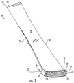
- FIG. 2 shows a schematic perspective view of a steam turbine rotor blade 20, e.g., within the L1 stage or L0 stage, according to various embodiments of the disclosure.
- steam turbine rotor blade 20 may include a blade or airfoil 22 having a leading edge 35, a trailing edge 37, a radially outer first end 24, and a radially inner second end 26 opposite first end 24.
- First end 24 of airfoil 22 can include a tip 28, which may be coupled to a shroud (not shown) in some embodiments.
- a base 30 which includes a dovetail 32 for engaging with and complementing a corresponding dovetail slot 36 in a rotor 34 ( FIG. 6 ).
- the rotor blade 20 may further include a platform 31 that generally surrounds the dovetail 32 and the airfoil 22.
- a typical platform may be positioned at an intersection or transition between the airfoil 22 and the dovetail 32 and may extend outwardly in the generally axial and tangential directions, as shown.
- the airfoil 22 may extend radially outward from the platform 31 and the dovetail 32 may extend radially inward from the platform 31.
- the platform 31 generally serves as a radially inward flow boundary for the working fluid flowing through the steam path.
- a groove or tapered groove 33 may extend along the radially inner portion of the dovetail 32.
- the dovetail 32 may extend between a leading edge face 25 radially inward from the leading edge 35 and a trailing edge face 27 radially inward from the trailing edge 37.
- the trailing edge face 27 may include a retention feature 54, discussed further herein.
- the tapered groove 33 may be deeper (i.e., extends radially deeper into the dovetail) near the leading edge face 25, and the depth of the groove 33 gradually reduces as it extends along the dovetail 32 to the trailing edge face 27.
- the depth of the tapered groove 33 near the leading edge face 25 may be about 0.30 inches and the depth of the groove 33 near the trailing edge face 27 may be about 0.12 inches.
- the depth of the tapered groove 33 near the leading edge face 25 may be between about 0.20 inches and about 0.40 inches.
- the depth of the groove 33 near the trailing edge face may be between about 0.08 inches and about 0.16 inches.
- FIG. 3 illustrates an enlarged perspective view of a portion of the steam turbine rotor blade 20.
- the dovetail 32 may include a main body 38, a plurality of projections 40 extending from the main body 38 in opposing directions, a radially innermost surface 46, and a tapered groove 33 extending within the radially innermost surface 46 along the length of the dovetail 32.
- the plurality of projections 40 are sized to complement a plurality of recesses 44 in the corresponding dovetail slot 36 ( FIG. 12 ).
- tapered groove 33 is open at the radially innermost surface 46 and is sized to engage a shim 52 ( FIG. 7 , in a manner shown in FIG. 12 ).
- Tapered groove 33 extends along the entirety of the radially innermost surface 46 of the main body 38.
- main body 38 includes a bulbous section 48 for complementing one of the plurality of recesses 44 in dovetail slot 36.
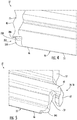
- FIG. 4 illustrates an enlarged perspective view of the leading edge surface 25 of a dovetail 32 in accordance with embodiments of the present disclosure.
- FIG. 5 illustrates an enlarged perspective view of the trailing edge surface 27.
- the dovetail 32 may further include a first corner 200 defined at an intersection between the leading edge surface 25 and the radially innermost surface 46 of the dovetail 32.
- a second corner 202 may be defined at an intersection between the trailing surface 27 and the radially innermost surface 46.
- the first corner 200 and the second corner 202 may be arcuate and/or generally smooth curved surfaces.
- the first corner 200 and second corner 202 may function at least partially to provide a smooth surface for the ends of the shim 52 to be bent around without causing the shim 52 to crack and/or break.
- the first corner 200, and/or the second corner 202 in some embodiments, may include an axial recess 204 relative to the leading edge surface 25.
- the axial recess 204 may include an axially extending portion 206 and a radially extending portion 208 that intersect with one another.
- the axially extending portion 206 may be generally perpendicular to the leading edge surface 25 and may extend between the leading edge surface 25 and the radially extending portion 208.
- the radially extending portion 208 may be generally parallel to the leading edge face 25 and may extend between the axially extending portion 206 and the first corner 200 and/or the radially innermost surface 46.
- the radially extending portion 208 of the axial recess 204 may be disposed axially inward from the leading edge surface 25.
- the second corner 202 may also include an axial recess 204 relative to the trailing edge surface 27.
- FIG. 6 illustrates a rotor 34 (e.g., a steam turbine rotor) including a plurality of dovetail slots 36 for coupling with dovetails 32 of rotor blades 20.
- Each dovetail slot 36 of the plurality of dovetail slots 36 includes a plurality of recesses 44 which may be sized to receive the plurality of projections 40 extending from each dovetail 32.
- each dovetail slot 36 may include a radially innermost surface 210. The radially innermost surface 210 of the dovetail slot 36 may contact either one or both of the radially innermost surface 46 of the dovetail 32 and/or the shim 52 when the dovetail 32 is installed in the dovetail slot 36.
- FIG. 7 and FIG. 8 illustrate shim 52 in greater detail.
- shim 52 may be sized to engage tapered groove 33 in rotor blade 20 and functions to retain rotor blade 20 within dovetail slot 36.
- shim 52 may include a main body 68 having a first thickness (t 1 ) measured between an upper surface or radially outer surface 70 and a lower surface or first radially inner surface 72 of the main body 68.
- a thinned region 74 may extend from one end of main body 68 (e.g., the thicker end of shim 52) and may include a second thickness (t 2 ) measured between radially outer surface 70 (which is continuous between main body 68 and thinned region 74) and a thinned radially inner surface or second radially inner surface 76.
- the second thickness (t 2 ) is between about 5 percent to about 70 percent of the first thickness (t 1 ). In other embodiments, the second thickness (t 2 ) is between about 15 percent to about 60 percent of the first thickness (t 1 ). In many embodiments, the second thickness (t 2 ) is between about 25 percent to about 50 percent of the first thickness (t 1 ). In various embodiments, the second thickness (t 2 ) is between about 35 percent to about 45 percent of the first thickness (t 1 ).
- Connecting main body 68 and thinned region 74 is a first tapered region 78, which is tapered outward from main body 68 to thinned region 74.
- thinned region 74 can have a length (1 TR ) equal to approximately one-quarter of a length (1 MB ) of main body 68, or one-eighth of a length of the main body 68, or three-sixteenths of a length of the main body 68, or between about 10% and about 25% of the length of the main body 68.
- the radially outer surface 70 may be in contact with the rotor blade 20
- the first radially inner surface 72 may be in contact with the rotor 34 to advantageously retain the rotor blade 20 within the dovetail slot 36. It is understood that shim 52 can be inserted in either a forward or aft direction into the tapered groove 33, depending upon clearances and desired installation techniques.
- shim 52 is configured to fit in tapered groove 33 and between dovetail 32 of rotor blade 20 and dovetail slot 36 of rotor 34 and to aid in retaining rotor blade 20 within rotor 34.
- thinned region 74 enhances ease of installation and removal of shim 52 within the tight clearances of the steam turbine. That is, thinned region 74 may permit flexing of shim 52 or bending over of an end of the shim 52 to lock the shim to rotor 34, e.g., bending the ends of the shim 52 over the first corner 200 and second corner 202 ( FIGS. 4 and 5 ).
- the thinned region 74 is preferably located on the thicker end of the shim 52, as the thicker end would be more difficult to bend over than the opposing thinner end.
- the region 74 is thinned to assure proper bend to thickness ratio such that cold working will not result in cracking or a high residual stressed area.
- the reduced thickness facilitates bending over a portion of the shim 52 to lock it to the rotor 34, and the opposing end portion near the thin end can also be bent over in a similar manner to lock the shim 52 to rotor 34.
- FIG. 9 illustrates a cut-away depiction of rotor blade 20 engaged with a rotor 34, and a portion of an axial retention member 64 within space 66 for axially retaining rotor blade 20 within rotor 34.
- rotor blade 20 may further include an axial retention feature 54 extending from a side 56 of body 38.
- the side 56 may be the leading edge surface 25, the trailing edge surface 27, or both.
- the axial retention feature extends from the trailing edge surface 27.
- axial retention feature 54 may include a hook 58 having a first member 60 extending generally perpendicular from the trailing edge face 27 and a second member 62 extending from first member 60 generally parallel to the trailing edge face 27. As described further herein, axial retention feature 54 may function to provide a space in which the axial retention member 64 may fit to axially retain the dovetail 32 within the dovetail slot 36. In various embodiments, axial retention feature 54 defines a space 66 between the second member 62 and the trailing edge face 27 that is sized to engage the axial retention member 64.
- FIG. 10 illustrates a perspective radially outwardly facing view of axial retention member 64 positioned relative to rotor 34, excluding blade(s) 20.
- axial retention member 64 further includes an anti-rotation tab 65 for engaging hook 58 ( FIG. 9 ) and for preventing rotation of axial retention member 64 within space 66 ( FIG. 9 ).
- an anti-rotation pin 67 may be coupled to rotor 34 to prevent radial movement of axial retention member 64 within space 66.
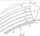
- FIGS. 11 and 12 illustrate perspective blown-out views of rotor blade 20, rotor 34, and shim 52.
- tapered groove 33 is disposed along the radially innermost surface 46 of the dovetail 32 of rotor blade 20, which is disposed opposite the radially innermost surface 210 within the dovetail slot 36 of rotor 34.
- the shim 52 may be sized to fit within the tapered groove 33 of dovetail 32 to space apart the radially innermost surface 210 of the dovetail slot 36 and the radially innermost surface 46 of the dovetail 32 such that the rotor blade 20 is properly restrained within the rotor 34 during various operations of the steam turbine 100.
- the shim 52 functions to provide a rigid solution that locks the dovetail 32 of the rotor blade 20 into the dovetail slot 36 of the rotor 34.
- the shim 52 may be rigid such that it retains the rotor blade 20 within the rotor 34 during operation of the steam turbine without bending, flexing, buckling or moving. In this way, the shim 52 may be advantageous over other flexible means of retaining a rotor blade 20 within the rotor 34 because it does not bend, flex, or move during operation of the steam turbine 100.
- the rotor blade 20 may be a L1 stage rotor blade 20 and/or L0 stage rotor blade 20, which means that the rotor blade 20 may be much larger and heavier when compared to rotor blades in the L2 and L3 stages.
- the L0 and/or L1 stage rotor blade 20 may be between about 20 inches and about 30 inches in length and may have a weight of over 20 lbs.
- the L0 and/or L1 stage rotor blade 20 may have a weight of over 100 lbs.
- the L0 and/or L1 stage rotor blade 20 may have a weight of over 200 lbs.
- the relatively large L0 and/or L1 stage rotor blade 20 will exert a much larger moment on the dovetail slot 36 of the rotor 34 when compared to the L2 and/or L3 stages.
- a flexible solution of retention such as a spring, that would be successful in retaining a smaller L2 and/or L3 stage rotor blade is not capable of containing the relatively larger and heavier L0 and/or L1 stage rotor blades 20 due to their size and weight.
- a robust and rigid retention solution such as the shim 52 shown and described herein, is needed to contain the large L0 and/or L1 rotor blades 20.
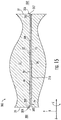
- FIG. 13 illustrates a simplified cross-sectional view of tapered groove 33, according to various embodiments.
- the tapered groove 33 may include a flat section 1101 near the leading edge surface 25 and/or the trailing edge surface 27, where the flat section 1101 has a constant depth (i.e., it is not tapered).
- the depth 1102 of the tapered groove 33 at the deep end is greater than the depth 1103 (and depth 1104) near the opposing end (right side of FIG. 13 ).
- the flat section 1101 has a constant depth 1104 across its length.
- the length of flat section 1101 may be about 3% to about 20% of the entire length of tapered groove 33.
- the length of flat section 1101 may be about 5% to about 18% of the entire length of tapered groove 33.
- the length of flat section 1101 may be about 7% to about 15% of the entire length of tapered groove 33.
- the length of flat section 1101 may be about 9% to about 13% of the entire length of tapered groove 33.
- the flat section 1101 facilitates disassembly/removal of the shim 52 after turbine operation and may also enable disassembly in the field without requiring the use of a cut-off tool.
- the flat section 1101 allows for a larger gap at the thin end of the wedge. This gap accommodates bending the thin end bend-over back to near-straight and then being able to tap the wedge towards the thick end. Without this additional gap area, the bending back of the end would form a "mushroomed" bend area and would not allow for easy disengagement of the thin end. Additionally, the flat section 1101 becomes the tertiary datum for machining and inspection of the blade as using the groove taper would not be prudent or robust.
- FIG. 14 illustrates a simplified, cross-sectional view of shim 52.
- the shim 52 includes a thick end 77 and an opposing thin end 75, and the overall thickness gradually transitions between opposing ends.
- the thinned region 74 is a region of reduced thickness that enables the shim 52 to be bent over the corner 200, 202 to lock the shim 52 in place. This is particularly effective when both ends of the shim are bent over the corners 200, 202, as the shim is prevented from moving in an axial direction (with respect to the turbine).
- a first end 75 of the shim 52 may have a first thickness 1202, and an opposing second end 77 of the shim may have a second thickness 1201, where the second thickness 1201 is greater than the first thickness 1202.
- the intermediate heights of the shim 52 gradually transition from the first height 1202 to the second height 1201.
- the shim 52 may be tapered to exactly match the dimensions of the tapered groove 33 such that the shim is securely housed and contained within the tapered groove 33. Accordingly, the shim 52 may be tapered to allow for easy insertion of the shim 52 into the tapered groove 33.
- the shim 52 having a taper may be advantageous over other types of shims, e.g., a flat shim, because it is easy to insert within the tapered groove 33.
- a tapered shim such as the tapered shim 52 shown and described herein, may be advantageous.
- the shim thinned region 74 may extend from the second (thicker) end 77 to the first tapered region 78.
- the first tapered region 78 may transition the shim 52 from the thinned region 74 to the main body 68.
- the shim 52 may increase in thickness from the thinned region 74 to the main body 68.
- the main body 68 of the shim may then gradually decrease in thickness from the first tapered region 78 to the first (thinner) end 75.
- FIG. 15 illustrates a rotor assembly 300 in accordance with embodiments of the present disclosure.
- the shim 52 may be installed in tapered groove 33 (not shown for clarity), and the ends of the shim 52 may be bent over the corners 200, 202. With both ends of the shim 52 bent over (as shown), the shim 52 is prevented from moving axially (i.e., left or right in FIG. 15 ) with respect to the wheel/rotor 34.
- the curved and/or arcuate corners 200, 202 may advantageously reduce cold-working stress on the shim 52 when the ends are bent during installation.
- the dovetail 32 may include a leading edge surface 25, a trailing edge surface 27, and a radially innermost surface 46 extending therebetween.
- a shim 52 may be positioned within a groove 33 (not shown) and between the radially innermost surface 46 of the dovetail 32 and the radially innermost surface 210 of the dovetail slot 36. As shown in FIG. 15 , the shim 52 may extend at least partially radially along both of the leading edge surface 25 and the trailing edge surface 27.
- the shim 52 may include a first radially extending portion 304 that extends along and contacts the leading edge surface 25, and a second radially extending portion 306 that extends along and contacts the trailing edge surface 27.
- An axially extending portion 308 may be disposed within the groove 33 and positioned between the radially innermost surface 46 of the dovetail 32 and the radially innermost surface 210 of the rotor 34 dovetail slot 36.
- the first radially extending portion 304, the second radially extending portion 306, and the axially extending portion 308 may extend continuously between one another.
- the first radially extending portion 304 of the shim 52 may transition to the axially extending portion 308 of the shim 52 at a first curved portion 305.
- the second radially extending portion 306 of the shim 52 may transition to the axially extending portion 308 of the shim 52 at a second curved portion 307.
- the first curved portion 305 of the shim 52 may be disposed between the first radially extending portion 304 and the axially extending portion 308.
- the first curved portion 305 of the shim 52 may extend along and contact the first corner 200, which is disposed between the leading edge surface 25 and the radially innermost surface 46 of the dovetail 32.
- the second curved portion 307 of the shim 52 may be disposed between the second radially extending portion 306 and the axially extending portion 308 of the shim 52. Further, the second curved portion 307 may extend along and contact the second corner 202, which is disposed between the trailing edge surface 27 and the radially innermost surface 46 of the dovetail 52. As shown and described herein, the first and the second radially extending portions 304, 306 of the shim 52 and the first and the second curved portions 305, 307 may function to advantageously provide axial retention of the dovetail 32 within the rotor 34.
- the first corner 200 of the dovetail 32 may be defined at an intersection between the leading edge surface 25 and the radially innermost surface 46 of the dovetail 32.
- the second corner 202 of the dovetail 32 may be defined at an intersection between the trailing edge surface 27 and the radially innermost surface 46 of the dovetail 32.
- the first corner and the second corner 200, 202 may be curved, arcuate, and/or substantially smooth surfaces that are positioned between the generally radially oriented leading edge and trailing edge surfaces 25, 27 and the generally axially oriented radially innermost surface 46 of the dovetail 32.
- the first and the second corners 200 may function to provide a smooth surface for the ends of shim 52 to be bent around during installation without cracking.
- the size of the radius of the corners 200, 202 is important because if, for example, the radius of the corner is too small (curve too small and angle too sharp), then the ends of the shim 52 may crack and/or break when bent over said corners 200, 202 during installation of the shim 52. Therefore, it is advantageous to have the radius of the corners 200, 202 be at least 150% of the thickness of the shim 52 at its ends. For example, in many embodiments, the radius of corners 200, 202 may be between about 150% and about 300% of the thickness of the shim 52 at its terminal ends 75, 77.
- the radius of corners 200, 202 may be between about 175% and about 275% of the thickness of the shim 52 at its terminal ends 75, 77. In various embodiments, the radius of corners 200, 202 may be between about 200% and about 250% of the thickness of the shim 52 at its terminal ends 75, 77. In particular embodiments, the radius of corners 200, 202 may be about 225% of the thickness of the shim 52 at its terminal ends 75, 77.
- first and the second corners 200, 202 onto the dovetail 32 may be advantageous to machine the first and the second corners 200, 202 onto the dovetail 32 as shown, instead of, for example, the rotor 34, for a variety of reasons.
- machining the first and second corners 200, 202 onto the dovetail 32 instead of the rotor may have less associated risk and be more cost effective.
- machining corners 200, 202 onto a rotor 34 may be difficult to machine due to the complex shape of the rotor 34, it may cause unwanted stress risers within the rotor 34, and it may result in scrapping of the relatively expensive rotor 34 if done incorrectly.
- machining the corners 200, 202 onto the dovetail 32 of the rotor blade 20 is much easier due to the geometry and size of the overall rotor blade 20 when compared to the rotor 34. Further, machining the corners 200, 202 onto the dovetail 32 has less associated risk when compared to the rotor 34 because the rotor blade 20 is a less expensive part to produce. Therefore, if an error were to occur during the machining of corners 200, 202, it would be much more cost effective to replace a single rotor blade 20 than the entire rotor 34.
- the shim 52 may further include a radially outer surface 70, a first radially inner surface 72, and a second radially inner surface 76.
- the radially outer surface 70 may extend continuously along and contact the leading edge surface 25, the first corner 200, the groove 33, the second corner 202, and the trailing edge surface 27 without any gaps or spaces in contact. It is advantageous to have the radially outer surface 70 of the shim 52 have as much contact with the radially innermost surface 46 of the dovetail 32 in order to maintain retention of the shim 52 during operation of the steam turbine 32.
- the first radially inner surface 72 may be spaced apart from the radially outer surface 70 and may extend along the radially innermost surface 210 of the dovetail slot 36.
- the second radially inner surface 76 may be spaced apart from the radially outer surface 70 and the radially innermost surface 210 of the rotor 34 dovetail slot 36. As shown, the second radially inner surface 76 may not be in contact with any other surfaces, i.e., it may be exposed to ambient air.
- FIG. 16 illustrates another a rotor assembly 300 in accordance with embodiments of the present disclosure.
- the rotor assembly 300 may further include a first axial recess 204 relative to the leading edge surface 25 and a second axial recess 205 relative to the trailing edge surface 27.
- each of the axial recesses 204, 205 may include an axially extending portion 206, 207 and a radially extending portion 208, 209 that intersect with one another.
- the axially extending portion 206 on the leading edge side may be generally perpendicular to the leading edge surface 25 and may extend between the leading edge surface 25 and the radially extending portion 208.
- the radially extending portion 208 may be generally parallel to the leading edge surface 25 and may extend between the axially extending portion 206 and the first corner 200 and/or the radially innermost surface 46.
- the axially extending portion 207 of the second axial recess 205 may be generally perpendicular to the trailing edge surface 27 and may extend between the trailing edge surface 27 and the radially extending portion 209.
- the radially extending portion 209 of the second axial recess 205 may be generally parallel to the trailing edge surface 27 and may extend between the axially extending portion 207 and the second corner 202 and/or the radially innermost surface 46.
- the radially extending portions 208, 209 of the axial recess 204, 205 may be axially spaced from either the leading edge surface 25 or the trailing edge surface 27 to provide a pocket that protects the ends of shim 52 from erosion caused by a steam path 302.
- the portions of the shim 52 that extend along the corners 200, 202 may be advantageously positioned outside of, or away from, the steam path 302 in order to prolong the life of the shim 52 and to prevent erosion of the ends. Unwanted erosion of the ends of the shim 52 may cause the shim 52 to back out of the groove 33 (that is, to become dislodged) during operation of the steam turbine 100.
- the axial recesses 204, 205 advantageously provide a protective pocket for the radially extending portions 304, 306 and the curved portions 305, 307 that are spaced away from the steam path 302 to prevent unwanted erosion.
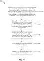
- FIG. 17 provides a flow chart, which graphically illustrates an example method 400 of installing a plurality of rotor blades within a rotor, such as the rotor blades 20 and rotor 34 described herein, in accordance with one or more example embodiments of the present disclosure.
- the method 400 may include a step 402 of machining a first recessed corner 200 and a second recessed corner 202 onto a dovetail 32 of each rotor blade 20 of the plurality of rotor blades 20.
- the first recessed corner 200 may be defined at an intersection between a leading edge surface 25 of the dovetail 32 and a radially innermost surface 46 of the dovetail 32.
- the second recessed corner 202 may be defined at an intersection between a trailing edge surface 27 of the dovetail 32 and the radially innermost surface 46 of the dovetail 32.
- the method 400 may further include a step 404 of engaging the dovetail 32 of each rotor blade 20 into a corresponding dovetail slot 36 defined within a rotor 34.
- a groove 33 may be defined between the radially innermost surface 46 of the dovetail 32 and the radially innermost surface 210 of the dovetail slot 36.
- the method 400 may also include a step 406 of inserting a shim 52 into the groove 33 until a first end 75 of the shim 52 extends axially beyond the trailing edge surface 27 and a second end 77 of the shim 52 extends axially beyond the leading edge surface 25.
- the method 400 may further include a step 408 of bending the first end 75 of the shim around the second recessed corner 202. In some embodiments, the method 400 may include a step 410 of bending the second end 77 of the shim 52 around the first recessed corner 200. In some embodiments, the step 406 occurs before either or both of step 408 and 410, in order to ensure that the shim is fully inserted into the groove 33. The order of steps 408 and 410 may be reversed.
Landscapes
- Engineering & Computer Science (AREA)
- Mechanical Engineering (AREA)
- General Engineering & Computer Science (AREA)
- Turbine Rotor Nozzle Sealing (AREA)
Abstract
Description
- The present disclosure relates generally to turbomachines. Specifically, present disclosure relates to support and/or retention of rotor blades in turbomachines.
- Turbomachines, such as steam turbines, often include static nozzle assemblies that direct flow of a working fluid into rotor blades connected to a rotating rotor. The nozzle construction (including a plurality of nozzles, or "airfoils") is sometimes referred to as a "diaphragm" or "nozzle assembly stage." Each rotor blade includes a base with a dovetail that is sized to fit within a corresponding dovetail slot in the rotor. Many last stage rotor blades are of significant length and have a substantial weight. During low speed operation or "turning gear" operation, the blades have the ability to move within the dovetail slots in which they are retained. This undesirable movement can cause significant wear on the blade and/or the rotor dovetail slots. In many cases, wear on the blades and dovetail slots can cause outages, require repairs, and result in undesirable costs.
- However, during rotor assembly, it is required to have some movement ("fanning") of the rotor blades to facilitate assembly of the rotor blades. The rotor blades have outer cover ends, and these typically have interlocking features. The rotor blades must pass each other during row assembly. The rotor blades may also overlap airfoils such that assembly of the last rotor blades in the row may be difficult, if not impossible, to assemble if adequate movement does not exist.
- Accordingly, an improved system and method for rotor blade installation is desired in the art. In particular, an improved system and method for rotor blade installation that allows for adequate clearance during assembly while maintaining proper restraint of the rotor blade during operation of the turbomachine is desired.
- Aspects and advantages of the present rotor assemblies, turbomachines, and methods of installing a plurality of rotor blades in a rotor assembly in accordance with the present disclosure will be set forth in part in the following description, or may be obvious from the description, or may be learned through practice of the technology.
- In accordance with one embodiment, a rotor assembly is provided. The rotor assembly includes a rotor having a dovetail slot. The dovetail slot includes a plurality of recesses and a first radially innermost surface. The rotor assembly further includes a shim and a rotor blade having a platform. An airfoil extends radially outward from the platform, and a dovetail extends radially inward from the platform. The dovetail includes a plurality of projections that extend in opposite directions and that are received by the plurality of recesses of the dovetail slot. The dovetail further includes a leading edge surface, a trailing edge surface, and a second radially innermost surface. The dovetail further includes a groove defined along the second radially innermost surface from the leading edge surface to the trailing edge surface. The shim is positioned within the groove and between the first radially innermost surface of the dovetail slot and the second radially innermost surface of the dovetail. The shim extends at least partially radially along both of the leading edge surface and the trailing edge surface.
- In accordance with another embodiment, a turbomachine is provided. The turbomachine includes at least one turbine section, a rotor shaft that extends axially through the at least one turbine section, and a rotor assembly that is coupled to the rotor shaft. The rotor assembly includes a rotor having a dovetail slot. The dovetail slot includes a plurality of recesses and a first radially innermost surface. The rotor assembly further includes a shim and a rotor blade having a platform. An airfoil extends radially outward from the platform, and a dovetail extends radially inward from the platform. The dovetail includes a plurality of projections that extend in opposite directions and that are received by the plurality of recesses of the dovetail slot. The dovetail includes a leading edge surface, a trailing edge surface, and a second radially innermost surface. The dovetail further includes a groove defined along the second radially innermost surface from the leading edge surface to the trailing edge surface. The shim is positioned within the groove and between the first radially innermost surface of the dovetail slot and the second radially innermost surface of the dovetail. The shim extends at least partially radially along both of the leading edge surface and the trailing edge surface.
- In accordance with yet another embodiment, a method of installing a plurality of rotor blades in a rotor assembly is provided. The method includes machining a first recessed corner and a second recessed corner onto a dovetail of each rotor blade of the plurality of rotor blades. The first recessed corner is defined at an intersection between a leading edge surface of the dovetail and a radially innermost surface of the dovetail. The second recessed corner is defined at an intersection between a trailing edge surface of the dovetail and the radially innermost surface. The method further includes engaging the dovetail of each rotor blade into a corresponding dovetail slot defined within a rotor. A groove is defined between the radially innermost surface of the dovetail and the radially innermost surface of the dovetail slot. The method further includes inserting a shim into groove until a first end of the shim extends axially beyond the trailing edge face and a second end of the shim extends axially beyond the leading edge face. The method further includes bending the first end of the shim around the second recessed corner and bending the second end of the shim around the first recessed corner.
- These and other features, aspects and advantages of the present rotor assemblies, turbomachines, and methods of installing a plurality of rotor blades in a rotor assembly will become better understood with reference to the following description and appended claims. The accompanying drawings, which are incorporated in and constitute a part of this specification, illustrate embodiments of the technology and, together with the description, serve to explain the principles of the technology.
- A full and enabling disclosure of the present rotor assemblies, turbomachines, and methods of installing a plurality of rotor blades in a rotor assembly, including the best mode of making and using the present systems and methods, directed to one of ordinary skill in the art, is set forth in the specification, which makes reference to the appended figures, in which:
-
FIG. 1 is a schematic illustration of a turbomachine in accordance with embodiments of the present disclosure; -
FIG. 2 illustrates a rotor blade in accordance with embodiments of the present disclosure; -
FIG. 3 illustrates an enlarged perspective view of a rotor blade in accordance with embodiments of the present disclosure; -
FIG. 4 illustrates an enlarged perspective view of a rotor blade dovetail in accordance with embodiments of the present disclosure; -
FIG. 5 illustrates an enlarged perspective view of a rotor blade dovetail in accordance with embodiments of the present disclosure; -
FIG. 6 illustrates an enlarged perspective view of a rotor showing the dovetail slots decoupled from the rotor blade dovetail in accordance with embodiments of the present disclosure; -
FIG. 7 illustrates a perspective view of a shim in accordance with embodiments of the present disclosure; -
FIG. 8 illustrates an enlarged perspective view of a shim in accordance with embodiments of the present disclosure; -
FIG. 9 illustrates a cut-away depiction of a rotor blade engaged with a rotor in accordance with embodiments of the present disclosure; -
FIG. 10 illustrates a perspective radially outwardly facing view of an axial retention member positioned relative to a rotor, excluding the rotor blades, in accordance with embodiments of the present disclosure; -
FIG. 11 illustrates a perspective blown-out view of a rotor blade dovetail and a shim in accordance with embodiments of the present disclosure; -
FIG. 12 illustrates a perspective blown-out view of a rotor blade dovetail, a shim, and a cut-away rotor in accordance with embodiments of the present disclosure; -
FIG. 13 illustrates a simplified cross-sectional view of a groove in accordance with embodiments of the present disclosure; -
FIG. 14 illustrates a cross-sectional view of a shim in accordance with embodiments of the present disclosure; -
FIG. 15 illustrates a cross-sectional view of a rotor assembly in accordance with embodiments of the present disclosure; -
FIG. 16 illustrates a cross-sectional view of a rotor assembly in accordance with embodiments of the present disclosure; and -
FIG. 17 is a flow chart illustrating a method in accordance with embodiments of the present disclosure. - Reference now will be made in detail to embodiments of the present rotor assemblies, turbomachines, and methods of installing a plurality of rotor blades in a rotor assembly, one or more examples of which are illustrated in the drawings. Each example is provided by way of explanation, rather than limitation of, the technology. In fact, it will be apparent to those skilled in the art that modifications and variations can be made in the present technology without departing from the scope or spirit of the claimed technology. For instance, features illustrated or described as part of one embodiment can be used with another embodiment to yield a still further embodiment. Thus, it is intended that the present disclosure covers such modifications and variations as come within the scope of the appended claims and their equivalents.
- The detailed description uses numerical and letter designations to refer to features in the drawings. Like or similar designations in the drawings and description have been used to refer to like or similar parts of the invention. As used herein, the terms "first", "second", and "third" may be used interchangeably to distinguish one component from another and are not intended to signify location or importance of the individual components.
- As used herein, the terms "upstream" (or "forward") and "downstream" (or "aft") refer to the relative direction with respect to fluid flow in a fluid pathway. For example, "upstream" refers to the direction from which the fluid flows, and "downstream" refers to the direction to which the fluid flows. The term "radially" refers to the relative direction that is substantially perpendicular to an axial centerline of a particular component, the term "axially" refers to the relative direction that is substantially parallel and/or coaxially aligned to an axial centerline of a particular component, and the term "circumferentially" refers to the relative direction that extends around the axial centerline of a particular component.
- Terms of approximation, such as "generally," "substantially," "approximately," or "about" include values within ten percent greater or less than the stated value. When used in the context of an angle or direction, such terms include within ten degrees greater or less than the stated angle or direction. For example, "generally vertical" includes directions within ten degrees of vertical in any direction, e.g., clockwise or counter-clockwise.
- Referring to the drawings,
FIG. 1 shows a schematic diagram of an exemplary opposed-flow steam turbine 100. Although an exemplary steam turbine is shown and described herein, the present disclosure is not limited to such embodiment or to a steam turbine unless otherwise specified in the claims. For example, the invention as described herein may be used in any type of turbomachine including, but not limited to, an industrial or land-based gas turbine, an aircraft gas turbine, or a marine gas turbine. As shown inFIG. 1 , thesteam turbine 100 may define an axial direction A and a circumferential direction C which extends around the axial direction A. Thesteam turbine 100 may also define a radial direction R perpendicular to the axial direction A. - As shown in
FIG. 1 ,steam turbine 100 may include a first low pressure (LP)section 105 and asecond LP section 110. EachLP section FIG. 1 ). In one embodiment, eachLP section - The L3 stage is the first stage of the margin stages in the axial direction A and the smallest in the radial direction R of the margin stages. The L2 stage is the third to last stage and is the next stage in the axial direction A. The L1 stage is next to last stage of the four margin stages. The L0 stage is the last stage and is the largest in a radial direction R. It is to be understood that four stages are described as one example only, and
LP sections - A
rotor shaft 115 extends throughLP sections LP section nozzle casing 130 may be divided along a horizontal plane and axially into upper andlower half sections casing 130 may span bothLP sections central section 145 ofshell 130 includes a lowpressure steam inlet 150. Within outer shell orcasing 130,LP sections journal bearings flow splitter 165 extends betweenLP sections - During operation, low
pressure steam inlet 150 receives low pressure/intermediate temperature steam 170 from a source, such as, but not limited to, a high pressure (HP) turbine or an intermediate (IP) turbine through a cross-over pipe (not shown).Steam 170 is channeled throughinlet 150 whereinflow splitter 165 splits the steam flow into twoopposite flow paths steam 170 is routed throughLP sections rotor shaft 115. The steam exitsLP sections - It should be noted that although
FIG. 1 illustrates an opposed-flow, low pressure turbine, as will be appreciated by one of ordinary skill in the art, the systems and methods of the present disclosure are not limited to being used only with LP turbines and can be used with any opposed-flow turbine including, but not limited to, IP turbines and/or HP turbines. In addition, the systems and methods of the present disclosure are not limited to only being used with opposed-flow turbines, but rather may also be used with other turbine types (e.g., single flow steam turbines). -
FIG. 2 shows a schematic perspective view of a steamturbine rotor blade 20, e.g., within the L1 stage or L0 stage, according to various embodiments of the disclosure. As shown, steamturbine rotor blade 20 may include a blade orairfoil 22 having a leadingedge 35, a trailingedge 37, a radially outerfirst end 24, and a radially innersecond end 26 oppositefirst end 24. First end 24 ofairfoil 22 can include atip 28, which may be coupled to a shroud (not shown) in some embodiments. Atsecond end 26 ofairfoil 22 is a base 30, which includes adovetail 32 for engaging with and complementing acorresponding dovetail slot 36 in a rotor 34 (FIG. 6 ). - The
rotor blade 20 may further include aplatform 31 that generally surrounds thedovetail 32 and theairfoil 22. A typical platform may be positioned at an intersection or transition between theairfoil 22 and thedovetail 32 and may extend outwardly in the generally axial and tangential directions, as shown. In various embodiments, theairfoil 22 may extend radially outward from theplatform 31 and thedovetail 32 may extend radially inward from theplatform 31. In many embodiments, theplatform 31 generally serves as a radially inward flow boundary for the working fluid flowing through the steam path. - As shown in
FIG. 2 , a groove or taperedgroove 33 may extend along the radially inner portion of thedovetail 32. Thedovetail 32 may extend between aleading edge face 25 radially inward from the leadingedge 35 and a trailingedge face 27 radially inward from the trailingedge 37. The trailingedge face 27 may include aretention feature 54, discussed further herein. - In some embodiments, the tapered
groove 33 may be deeper (i.e., extends radially deeper into the dovetail) near theleading edge face 25, and the depth of thegroove 33 gradually reduces as it extends along thedovetail 32 to the trailingedge face 27. As one non-limiting example, the depth of the taperedgroove 33 near theleading edge face 25 may be about 0.30 inches and the depth of thegroove 33 near the trailingedge face 27 may be about 0.12 inches. In other embodiments, the depth of the taperedgroove 33 near theleading edge face 25 may be between about 0.20 inches and about 0.40 inches. Likewise, in some embodiments, the depth of thegroove 33 near the trailing edge face may be between about 0.08 inches and about 0.16 inches. -
FIG. 3 illustrates an enlarged perspective view of a portion of the steamturbine rotor blade 20. As shown, thedovetail 32 may include amain body 38, a plurality ofprojections 40 extending from themain body 38 in opposing directions, a radiallyinnermost surface 46, and a taperedgroove 33 extending within the radiallyinnermost surface 46 along the length of thedovetail 32. The plurality ofprojections 40 are sized to complement a plurality ofrecesses 44 in the corresponding dovetail slot 36 (FIG. 12 ). In various embodiments, taperedgroove 33 is open at the radiallyinnermost surface 46 and is sized to engage a shim 52 (FIG. 7 , in a manner shown inFIG. 12 ).Tapered groove 33 extends along the entirety of the radiallyinnermost surface 46 of themain body 38. In various embodiments,main body 38 includes abulbous section 48 for complementing one of the plurality ofrecesses 44 indovetail slot 36. -
FIG. 4 illustrates an enlarged perspective view of theleading edge surface 25 of adovetail 32 in accordance with embodiments of the present disclosure. Similarly,FIG. 5 illustrates an enlarged perspective view of the trailingedge surface 27. As shown, thedovetail 32 may further include afirst corner 200 defined at an intersection between theleading edge surface 25 and the radiallyinnermost surface 46 of thedovetail 32. Likewise, asecond corner 202 may be defined at an intersection between the trailingsurface 27 and the radiallyinnermost surface 46. As shown inFIGS. 4 and 5 , thefirst corner 200 and thesecond corner 202 may be arcuate and/or generally smooth curved surfaces. In many embodiments, thefirst corner 200 andsecond corner 202 may function at least partially to provide a smooth surface for the ends of theshim 52 to be bent around without causing theshim 52 to crack and/or break. - As shown in
FIG. 4 thefirst corner 200, and/or thesecond corner 202 in some embodiments, may include anaxial recess 204 relative to theleading edge surface 25. In particular, theaxial recess 204 may include anaxially extending portion 206 and aradially extending portion 208 that intersect with one another. Specifically, theaxially extending portion 206 may be generally perpendicular to theleading edge surface 25 and may extend between theleading edge surface 25 and theradially extending portion 208. Theradially extending portion 208 may be generally parallel to theleading edge face 25 and may extend between theaxially extending portion 206 and thefirst corner 200 and/or the radiallyinnermost surface 46. Theradially extending portion 208 of theaxial recess 204 may be disposed axially inward from the leadingedge surface 25. Although not shown inFIG. 5 , in many embodiments, thesecond corner 202 may also include anaxial recess 204 relative to the trailingedge surface 27. -
FIG. 6 illustrates a rotor 34 (e.g., a steam turbine rotor) including a plurality ofdovetail slots 36 for coupling with dovetails 32 ofrotor blades 20. Eachdovetail slot 36 of the plurality ofdovetail slots 36 includes a plurality ofrecesses 44 which may be sized to receive the plurality ofprojections 40 extending from eachdovetail 32. Further, as shown inFIG. 6 , eachdovetail slot 36 may include a radiallyinnermost surface 210. The radiallyinnermost surface 210 of thedovetail slot 36 may contact either one or both of the radiallyinnermost surface 46 of thedovetail 32 and/or theshim 52 when thedovetail 32 is installed in thedovetail slot 36. -
FIG. 7 andFIG. 8 illustrateshim 52 in greater detail. In various embodiments,shim 52 may be sized to engage taperedgroove 33 inrotor blade 20 and functions to retainrotor blade 20 withindovetail slot 36. In many embodiments,shim 52 may include amain body 68 having a first thickness (t1) measured between an upper surface or radiallyouter surface 70 and a lower surface or first radiallyinner surface 72 of themain body 68. A thinnedregion 74 may extend from one end of main body 68 (e.g., the thicker end of shim 52) and may include a second thickness (t2) measured between radially outer surface 70 (which is continuous betweenmain body 68 and thinned region 74) and a thinned radially inner surface or second radiallyinner surface 76. - In some embodiments, the second thickness (t2) is between about 5 percent to about 70 percent of the first thickness (t1). In other embodiments, the second thickness (t2) is between about 15 percent to about 60 percent of the first thickness (t1). In many embodiments, the second thickness (t2) is between about 25 percent to about 50 percent of the first thickness (t1). In various embodiments, the second thickness (t2) is between about 35 percent to about 45 percent of the first thickness (t1). Connecting
main body 68 and thinnedregion 74 is a firsttapered region 78, which is tapered outward frommain body 68 to thinnedregion 74. In various embodiments, thinnedregion 74 can have a length (1TR) equal to approximately one-quarter of a length (1MB) ofmain body 68, or one-eighth of a length of themain body 68, or three-sixteenths of a length of themain body 68, or between about 10% and about 25% of the length of themain body 68. - In many embodiments, when the
shim 52 is installed between arotor 34 and arotor blade 20, the radiallyouter surface 70 may be in contact with therotor blade 20, and the first radiallyinner surface 72 may be in contact with therotor 34 to advantageously retain therotor blade 20 within thedovetail slot 36. It is understood thatshim 52 can be inserted in either a forward or aft direction into the taperedgroove 33, depending upon clearances and desired installation techniques. - As described herein,
shim 52 is configured to fit in taperedgroove 33 and betweendovetail 32 ofrotor blade 20 anddovetail slot 36 ofrotor 34 and to aid in retainingrotor blade 20 withinrotor 34. Further, in various embodiments, thinnedregion 74 enhances ease of installation and removal ofshim 52 within the tight clearances of the steam turbine. That is, thinnedregion 74 may permit flexing ofshim 52 or bending over of an end of theshim 52 to lock the shim torotor 34, e.g., bending the ends of theshim 52 over thefirst corner 200 and second corner 202 (FIGS. 4 and 5 ). - The thinned
region 74 is preferably located on the thicker end of theshim 52, as the thicker end would be more difficult to bend over than the opposing thinner end. Theregion 74 is thinned to assure proper bend to thickness ratio such that cold working will not result in cracking or a high residual stressed area. The reduced thickness facilitates bending over a portion of theshim 52 to lock it to therotor 34, and the opposing end portion near the thin end can also be bent over in a similar manner to lock theshim 52 torotor 34. - An important reason the bend-over is required at the thick end is because during operation the radial gap between the
rotor dovetail bottom 210 and the blade dovetail bottom 46 can increase due to mechanical growth. This radial gap would allow the wedge or shim to move towards the thin end during operation and then during shut down the radial gap would return to normal height. As the wedge/shim may have move forward and filled the larger gap there would be no room during shutdown for the blade to return to a non-stressed state. The radial gap being filled would result in excessive compression of the wedge/shim such that stresses could be beyond yield and/or disassembly of the wedge and it would be virtually impossible to remove the wedge/shim due to extremely high compression loading. -
FIG. 9 illustrates a cut-away depiction ofrotor blade 20 engaged with arotor 34, and a portion of anaxial retention member 64 withinspace 66 for axially retainingrotor blade 20 withinrotor 34. As shown inFIG. 9 ,rotor blade 20 may further include anaxial retention feature 54 extending from aside 56 ofbody 38. In many embodiments, theside 56 may be theleading edge surface 25, the trailingedge surface 27, or both. However, in the embodiment shown inFIG. 9 , the axial retention feature extends from the trailingedge surface 27. In many embodiments,axial retention feature 54 may include ahook 58 having afirst member 60 extending generally perpendicular from the trailingedge face 27 and asecond member 62 extending fromfirst member 60 generally parallel to the trailingedge face 27. As described further herein,axial retention feature 54 may function to provide a space in which theaxial retention member 64 may fit to axially retain thedovetail 32 within thedovetail slot 36. In various embodiments,axial retention feature 54 defines aspace 66 between thesecond member 62 and the trailingedge face 27 that is sized to engage theaxial retention member 64. -
FIG. 10 illustrates a perspective radially outwardly facing view ofaxial retention member 64 positioned relative torotor 34, excluding blade(s) 20. In some cases,axial retention member 64 further includes ananti-rotation tab 65 for engaging hook 58 (FIG. 9 ) and for preventing rotation ofaxial retention member 64 within space 66 (FIG. 9 ). Additionally, ananti-rotation pin 67 may be coupled torotor 34 to prevent radial movement ofaxial retention member 64 withinspace 66. -
FIGS. 11 and12 illustrate perspective blown-out views ofrotor blade 20,rotor 34, andshim 52. As shown inFIG. 11 , taperedgroove 33 is disposed along the radiallyinnermost surface 46 of thedovetail 32 ofrotor blade 20, which is disposed opposite the radiallyinnermost surface 210 within thedovetail slot 36 ofrotor 34. Likewise, theshim 52 may be sized to fit within the taperedgroove 33 ofdovetail 32 to space apart the radiallyinnermost surface 210 of thedovetail slot 36 and the radiallyinnermost surface 46 of thedovetail 32 such that therotor blade 20 is properly restrained within therotor 34 during various operations of thesteam turbine 100. - In many embodiments, the
shim 52 functions to provide a rigid solution that locks thedovetail 32 of therotor blade 20 into thedovetail slot 36 of therotor 34. Further, in various embodiments, theshim 52 may be rigid such that it retains therotor blade 20 within therotor 34 during operation of the steam turbine without bending, flexing, buckling or moving. In this way, theshim 52 may be advantageous over other flexible means of retaining arotor blade 20 within therotor 34 because it does not bend, flex, or move during operation of thesteam turbine 100. - As described herein, the
rotor blade 20 may be a L1stage rotor blade 20 and/or L0stage rotor blade 20, which means that therotor blade 20 may be much larger and heavier when compared to rotor blades in the L2 and L3 stages. For example, the L0 and/or L1stage rotor blade 20 may be between about 20 inches and about 30 inches in length and may have a weight of over 20 lbs. In some embodiments, the L0 and/or L1stage rotor blade 20 may have a weight of over 100 lbs. In other embodiments, the L0 and/or L1stage rotor blade 20 may have a weight of over 200 lbs. As such, the relatively large L0 and/or L1stage rotor blade 20 will exert a much larger moment on thedovetail slot 36 of therotor 34 when compared to the L2 and/or L3 stages. Thus, a flexible solution of retention, such as a spring, that would be successful in retaining a smaller L2 and/or L3 stage rotor blade is not capable of containing the relatively larger and heavier L0 and/or L1stage rotor blades 20 due to their size and weight. Accordingly, a robust and rigid retention solution, such as theshim 52 shown and described herein, is needed to contain the large L0 and/orL1 rotor blades 20. -
FIG. 13 illustrates a simplified cross-sectional view of taperedgroove 33, according to various embodiments. As shown, the taperedgroove 33 may include aflat section 1101 near the leadingedge surface 25 and/or the trailingedge surface 27, where theflat section 1101 has a constant depth (i.e., it is not tapered). Thedepth 1102 of the taperedgroove 33 at the deep end (left side ofFIG. 13 ) is greater than the depth 1103 (and depth 1104) near the opposing end (right side ofFIG. 13 ). - The
flat section 1101 has aconstant depth 1104 across its length. In some embodiments, the length offlat section 1101 may be about 3% to about 20% of the entire length of taperedgroove 33. In other embodiments, the length offlat section 1101 may be about 5% to about 18% of the entire length of taperedgroove 33. In various embodiments, the length offlat section 1101 may be about 7% to about 15% of the entire length of taperedgroove 33. In many embodiments, the length offlat section 1101 may be about 9% to about 13% of the entire length of taperedgroove 33. - The
flat section 1101 facilitates disassembly/removal of theshim 52 after turbine operation and may also enable disassembly in the field without requiring the use of a cut-off tool. Theflat section 1101 allows for a larger gap at the thin end of the wedge. This gap accommodates bending the thin end bend-over back to near-straight and then being able to tap the wedge towards the thick end. Without this additional gap area, the bending back of the end would form a "mushroomed" bend area and would not allow for easy disengagement of the thin end. Additionally, theflat section 1101 becomes the tertiary datum for machining and inspection of the blade as using the groove taper would not be prudent or robust. -
FIG. 14 illustrates a simplified, cross-sectional view ofshim 52. Theshim 52 includes athick end 77 and an opposingthin end 75, and the overall thickness gradually transitions between opposing ends. The thinnedregion 74 is a region of reduced thickness that enables theshim 52 to be bent over thecorner shim 52 in place. This is particularly effective when both ends of the shim are bent over thecorners first end 75 of theshim 52 may have afirst thickness 1202, and an opposingsecond end 77 of the shim may have asecond thickness 1201, where thesecond thickness 1201 is greater than thefirst thickness 1202. The intermediate heights of theshim 52 gradually transition from thefirst height 1202 to thesecond height 1201. - As shown and described herein, the
shim 52 may be tapered to exactly match the dimensions of the taperedgroove 33 such that the shim is securely housed and contained within the taperedgroove 33. Accordingly, theshim 52 may be tapered to allow for easy insertion of theshim 52 into the taperedgroove 33. As such, theshim 52 having a taper may be advantageous over other types of shims, e.g., a flat shim, because it is easy to insert within the taperedgroove 33. For example, due to the tight tolerances and substantial weight of the L0 and/orL1 rotor blade 20, insertion of a flat shim may be difficult or impossible. Thus, a tapered shim, such as the taperedshim 52 shown and described herein, may be advantageous. - In many embodiments, the shim thinned
region 74 may extend from the second (thicker) end 77 to the firsttapered region 78. The firsttapered region 78 may transition theshim 52 from the thinnedregion 74 to themain body 68. In various embodiments, as shown, theshim 52 may increase in thickness from the thinnedregion 74 to themain body 68. In many embodiments, themain body 68 of the shim may then gradually decrease in thickness from the firsttapered region 78 to the first (thinner)end 75. -
FIG. 15 illustrates arotor assembly 300 in accordance with embodiments of the present disclosure. As shown inFIG. 15 , theshim 52 may be installed in tapered groove 33 (not shown for clarity), and the ends of theshim 52 may be bent over thecorners shim 52 bent over (as shown), theshim 52 is prevented from moving axially (i.e., left or right inFIG. 15 ) with respect to the wheel/rotor 34. The curved and/orarcuate corners shim 52 when the ends are bent during installation. - As shown in
FIG. 15 , thedovetail 32 may include aleading edge surface 25, a trailingedge surface 27, and a radiallyinnermost surface 46 extending therebetween. In many embodiments, ashim 52 may be positioned within a groove 33 (not shown) and between the radiallyinnermost surface 46 of thedovetail 32 and the radiallyinnermost surface 210 of thedovetail slot 36. As shown inFIG. 15 , theshim 52 may extend at least partially radially along both of theleading edge surface 25 and the trailingedge surface 27. In many embodiments, as shown, theshim 52 may include a firstradially extending portion 304 that extends along and contacts theleading edge surface 25, and a secondradially extending portion 306 that extends along and contacts the trailingedge surface 27. An axially extendingportion 308 may be disposed within thegroove 33 and positioned between the radiallyinnermost surface 46 of thedovetail 32 and the radiallyinnermost surface 210 of therotor 34dovetail slot 36. - In various embodiments, the first radially extending
portion 304, the second radially extendingportion 306, and theaxially extending portion 308 may extend continuously between one another. For example, the first radially extendingportion 304 of theshim 52 may transition to theaxially extending portion 308 of theshim 52 at a firstcurved portion 305. Similarly, the second radially extendingportion 306 of theshim 52 may transition to theaxially extending portion 308 of theshim 52 at a secondcurved portion 307. As shown inFIG. 15 , the firstcurved portion 305 of theshim 52 may be disposed between the first radially extendingportion 304 and theaxially extending portion 308. In many embodiments, the firstcurved portion 305 of theshim 52 may extend along and contact thefirst corner 200, which is disposed between theleading edge surface 25 and the radiallyinnermost surface 46 of thedovetail 32. - Likewise, the second
curved portion 307 of theshim 52 may be disposed between the second radially extendingportion 306 and theaxially extending portion 308 of theshim 52. Further, the secondcurved portion 307 may extend along and contact thesecond corner 202, which is disposed between the trailingedge surface 27 and the radiallyinnermost surface 46 of thedovetail 52. As shown and described herein, the first and the second radially extendingportions shim 52 and the first and the secondcurved portions dovetail 32 within therotor 34. - As shown in
FIG. 15 , thefirst corner 200 of thedovetail 32 may be defined at an intersection between theleading edge surface 25 and the radiallyinnermost surface 46 of thedovetail 32. Likewise, thesecond corner 202 of thedovetail 32 may be defined at an intersection between the trailingedge surface 27 and the radiallyinnermost surface 46 of thedovetail 32. As shown, the first corner and thesecond corner innermost surface 46 of thedovetail 32. - The first and the
second corners 200 may function to provide a smooth surface for the ends ofshim 52 to be bent around during installation without cracking. The size of the radius of thecorners shim 52 may crack and/or break when bent over saidcorners shim 52. Therefore, it is advantageous to have the radius of thecorners shim 52 at its ends. For example, in many embodiments, the radius ofcorners shim 52 at its terminal ends 75, 77. In other embodiments, the radius ofcorners shim 52 at its terminal ends 75, 77. In various embodiments, the radius ofcorners shim 52 at its terminal ends 75, 77. In particular embodiments, the radius ofcorners shim 52 at its terminal ends 75, 77. - It may be advantageous to machine the first and the
second corners dovetail 32 as shown, instead of, for example, therotor 34, for a variety of reasons. In particular, machining the first andsecond corners dovetail 32 instead of the rotor may have less associated risk and be more cost effective. For example, machiningcorners rotor 34 may be difficult to machine due to the complex shape of therotor 34, it may cause unwanted stress risers within therotor 34, and it may result in scrapping of the relativelyexpensive rotor 34 if done incorrectly. However, machining thecorners dovetail 32 of therotor blade 20 is much easier due to the geometry and size of theoverall rotor blade 20 when compared to therotor 34. Further, machining thecorners dovetail 32 has less associated risk when compared to therotor 34 because therotor blade 20 is a less expensive part to produce. Therefore, if an error were to occur during the machining ofcorners single rotor blade 20 than theentire rotor 34. - As shown in
FIGS. 14 and15 , theshim 52 may further include a radiallyouter surface 70, a first radiallyinner surface 72, and a second radiallyinner surface 76. As shown, the radiallyouter surface 70 may extend continuously along and contact theleading edge surface 25, thefirst corner 200, thegroove 33, thesecond corner 202, and the trailingedge surface 27 without any gaps or spaces in contact. It is advantageous to have the radiallyouter surface 70 of theshim 52 have as much contact with the radiallyinnermost surface 46 of thedovetail 32 in order to maintain retention of theshim 52 during operation of thesteam turbine 32. The first radiallyinner surface 72 may be spaced apart from the radiallyouter surface 70 and may extend along the radiallyinnermost surface 210 of thedovetail slot 36. The second radiallyinner surface 76 may be spaced apart from the radiallyouter surface 70 and the radiallyinnermost surface 210 of therotor 34dovetail slot 36. As shown, the second radiallyinner surface 76 may not be in contact with any other surfaces, i.e., it may be exposed to ambient air. -
FIG. 16 illustrates another arotor assembly 300 in accordance with embodiments of the present disclosure. As shown, therotor assembly 300 may further include a firstaxial recess 204 relative to theleading edge surface 25 and a secondaxial recess 205 relative to the trailingedge surface 27. In particular, each of theaxial recesses axially extending portion radially extending portion axially extending portion 206 on the leading edge side may be generally perpendicular to theleading edge surface 25 and may extend between theleading edge surface 25 and theradially extending portion 208. Theradially extending portion 208 may be generally parallel to theleading edge surface 25 and may extend between theaxially extending portion 206 and thefirst corner 200 and/or the radiallyinnermost surface 46. Similarly, theaxially extending portion 207 of the secondaxial recess 205 may be generally perpendicular to the trailingedge surface 27 and may extend between the trailingedge surface 27 and theradially extending portion 209. Theradially extending portion 209 of the secondaxial recess 205 may be generally parallel to the trailingedge surface 27 and may extend between theaxially extending portion 207 and thesecond corner 202 and/or the radiallyinnermost surface 46. - The
radially extending portions axial recess leading edge surface 25 or the trailingedge surface 27 to provide a pocket that protects the ends ofshim 52 from erosion caused by asteam path 302. In this way, the portions of theshim 52 that extend along thecorners steam path 302 in order to prolong the life of theshim 52 and to prevent erosion of the ends. Unwanted erosion of the ends of theshim 52 may cause theshim 52 to back out of the groove 33 (that is, to become dislodged) during operation of thesteam turbine 100. Accordingly, theaxial recesses radially extending portions curved portions steam path 302 to prevent unwanted erosion. -
FIG. 17 provides a flow chart, which graphically illustrates anexample method 400 of installing a plurality of rotor blades within a rotor, such as therotor blades 20 androtor 34 described herein, in accordance with one or more example embodiments of the present disclosure. As illustrated inFIG. 17 , themethod 400 may include astep 402 of machining a first recessedcorner 200 and a second recessedcorner 202 onto adovetail 32 of eachrotor blade 20 of the plurality ofrotor blades 20. The first recessedcorner 200 may be defined at an intersection between aleading edge surface 25 of thedovetail 32 and a radiallyinnermost surface 46 of thedovetail 32. The second recessedcorner 202 may be defined at an intersection between a trailingedge surface 27 of thedovetail 32 and the radiallyinnermost surface 46 of thedovetail 32. - In many embodiments, the
method 400 may further include astep 404 of engaging thedovetail 32 of eachrotor blade 20 into acorresponding dovetail slot 36 defined within arotor 34. Agroove 33 may be defined between the radiallyinnermost surface 46 of thedovetail 32 and the radiallyinnermost surface 210 of thedovetail slot 36. In various embodiments, themethod 400 may also include astep 406 of inserting ashim 52 into thegroove 33 until afirst end 75 of theshim 52 extends axially beyond the trailingedge surface 27 and asecond end 77 of theshim 52 extends axially beyond the leadingedge surface 25. In many embodiments, themethod 400 may further include astep 408 of bending thefirst end 75 of the shim around the second recessedcorner 202. In some embodiments, themethod 400 may include astep 410 of bending thesecond end 77 of theshim 52 around the first recessedcorner 200. In some embodiments, thestep 406 occurs before either or both ofstep groove 33. The order ofsteps - This written description uses examples to disclose the invention, including the best mode, and also to enable any person skilled in the art to practice the invention, including making and using any devices or systems and performing any incorporated methods. The patentable scope of the invention is defined by the claims and may include other examples that occur to those skilled in the art. Such other examples are intended to be within the scope of the claims if they include structural elements that do not differ from the literal language of the claims, or if they include equivalent structural elements with insubstantial differences from the literal language of the claims.
Claims (12)
- A rotor assembly (300) comprising:a rotor (34) having a dovetail slot (36), the dovetail slot (36) including a plurality of recesses (44) and a first radially innermost surface (210);a shim (52); anda rotor blade (20) having a platform (31), an airfoil (22) extending radially outward from the platform (31), and a dovetail (32) extending radially inward from the platform (31), the dovetail (32) including a plurality of projections (40) extending in opposite directions that are received by the plurality of recesses (44) of the dovetail slot (36), the dovetail (32) comprising:a leading edge surface (25);a trailing edge surface (27);a second radially innermost surface (46); anda groove (33) defined along the second radially innermost surface (46) from the leading edge surface (25) to the trailing edge surface (27), wherein the shim (52) is positioned within the groove (33) and between the first radially innermost surface (210) and the second radially innermost surface (46), and wherein the shim (52) extends at least partially radially along both of the leading edge surface (25) and the trailing edge surface (27).
- The rotor assembly (300) as in claim 1, wherein the shim (52) comprises a first radially extending portion (304) that extends along and contacts the leading edge surface (25), a second radially extending portion (306) that extends along and contacts the trailing edge surface (27), and an axially extending portion that is disposed within the groove (33) and between the first radially innermost surface (210) and the second radially innermost surface (46).
- The rotor assembly (300) as in claim 1, wherein a first corner (200) is defined at an intersection between the leading edge surface (25) and the second radially innermost surface (46), and a second corner (202) is defined at an intersection between the trailing surface and the second radially innermost surface (46), wherein the first corner (200) and the second corner (202) are arcuate.
- The rotor assembly (300) as in claim 3, wherein the first corner (200) is axially recessed relative to the leading edge surface (25), and the second corner (202) is axially recessed relative to the trailing edge surface (27).
- The rotor assembly (300) as in claim 4, wherein the shim (52) is positioned in contact with the first corner (200) and the second corner (202), such that the shim (52) is outside of a steam path.
- The rotor assembly (300) as in claim 3, wherein the shim (52) comprises a radially outer surface (70) that extends along and contacts the leading edge surface (25), the first corner (200), the groove (33), the second corner (202), and the trailing edge surface (27).
- The rotor assembly (300) as in claim 2, wherein the shim (52) comprises a first radially inner surface (72) that extends along the first radially innermost surface (210) of the dovetail slot (36) and a second radially inner surface (76) that is spaced apart from the first radially innermost surface (210) of the dovetail slot (36).
- The rotor assembly (300) as in claim 1, wherein the groove (33) includes a depth defined radially within the dovetail (32), and wherein the depth changes from the leading edge surface (25) to the trailing edge surface (27).
- The rotor assembly (300) as in claim 1, wherein the groove (33) includes a first depth at the leading edge face and a second depth at the trailing edge face, and wherein the groove (33) gradually tapers from the first depth to the second depth along the second radially innermost surface (46).
- A method of installing a plurality of rotor blades (20) in a rotor assembly (300), the method comprising:machining a first recessed corner and a second recessed corner onto a dovetail (32) of each rotor blade (20) of the plurality of rotor blades (20), wherein the first recessed corner is defined at an intersection between a leading edge surface (25) of the dovetail (32) and a radially innermost surface of the dovetail (32), and the second corner is defined at an intersection between a trailing edge surface (27) of the dovetail (32) and the radially innermost surface;engaging the dovetail (32) of each rotor blade (20) into a corresponding dovetail slot (36) defined within a rotor (34), wherein a groove (33) is defined between the radially innermost surface of the dovetail (32) and the radially innermost surface of the dovetail slot (36);inserting a shim (52) into groove (33) until a first end of the shim (52) extends axially beyond the trailing edge face and a second end of the shim (52) extends axially beyond the leading edge face;bending the first end of the shim (52) around the second recessed corner; andbending the second end of the shim (52) around the first recessed corner.
- The method as in claim 10, wherein the step of bending the first end of the shim (52) around the second recessed corner results in the first end of the shim (52) no longer extending axially beyond the trailing edge surface (27).
- The method as in claim 10, wherein the step of bending the second end of the shim (52) around the first recessed corner results in the second end of the shim (52) no longer extending axially beyond the leading edge surface (25).
Applications Claiming Priority (1)
| Application Number | Priority Date | Filing Date | Title |
|---|---|---|---|
| US16/877,541 US11555407B2 (en) | 2020-05-19 | 2020-05-19 | Turbomachine rotor assembly |
Publications (2)
| Publication Number | Publication Date |
|---|---|
| EP3913191A1 true EP3913191A1 (en) | 2021-11-24 |
| EP3913191B1 EP3913191B1 (en) | 2023-06-28 |
Family
ID=75825460
Family Applications (1)
| Application Number | Title | Priority Date | Filing Date |
|---|---|---|---|
| EP21172158.4A Active EP3913191B1 (en) | 2020-05-19 | 2021-05-04 | Rotor assembly and method of installing a plurality of rotor blades in a rotor assembly |
Country Status (4)
| Country | Link |
|---|---|
| US (1) | US11555407B2 (en) |
| EP (1) | EP3913191B1 (en) |
| JP (1) | JP7706927B2 (en) |
| CN (1) | CN113685232B (en) |
Families Citing this family (1)
| Publication number | Priority date | Publication date | Assignee | Title |
|---|---|---|---|---|
| JP2024030955A (en) * | 2022-08-25 | 2024-03-07 | 株式会社東芝 | Rotor blade fixing method and rotor blade fixing structure |
Citations (4)
| Publication number | Priority date | Publication date | Assignee | Title |
|---|---|---|---|---|
| US3157385A (en) * | 1961-10-17 | 1964-11-17 | Ass Elect Ind | Blade locking means for turbines or compressors |
| US20190120069A1 (en) * | 2017-10-24 | 2019-04-25 | General Electric Company | Connection assemblies between turbine rotor blades and rotor wheels |
| WO2020102617A1 (en) * | 2018-11-15 | 2020-05-22 | General Electric Company | Turbine blade with radial support, shim and related turbine rotor |
| WO2020102615A1 (en) * | 2018-11-15 | 2020-05-22 | General Electric Company | Turbine blade with radial support, shim and related turbine rotor |
Family Cites Families (56)
| Publication number | Priority date | Publication date | Assignee | Title |
|---|---|---|---|---|
| US1719415A (en) * | 1927-09-14 | 1929-07-02 | Westinghouse Electric & Mfg Co | Turbine-blade attachment |
| US2801074A (en) * | 1952-10-01 | 1957-07-30 | United Aircraft Corp | Blade retaining means |
| US2942842A (en) | 1956-06-13 | 1960-06-28 | Gen Motors Corp | Turbine blade lock |
| US2971743A (en) | 1957-08-14 | 1961-02-14 | Gen Motors Corp | Interlocked blade shrouding |
| US3045329A (en) * | 1959-07-30 | 1962-07-24 | Gen Electric | Method for assembling tongue-and-groove members with locking keys |
| US3556675A (en) | 1969-01-29 | 1971-01-19 | Gen Electric | Turbomachinery rotor with integral shroud |
| US4265595A (en) | 1979-01-02 | 1981-05-05 | General Electric Company | Turbomachinery blade retaining assembly |
| JPS5697501U (en) * | 1979-12-25 | 1981-08-01 | ||
| FR2519692B1 (en) | 1982-01-14 | 1986-08-22 | Snecma | DEVICE FOR AXIAL LOCKING OF TURBINE BLADES AND COMPRESSORS |
| FR2535794A1 (en) | 1982-11-08 | 1984-05-11 | Snecma | AXIAL AND RADIAL BLADE SUPPORT DEVICE |
| JPS60131601U (en) * | 1984-02-10 | 1985-09-03 | 株式会社東芝 | Moving blade fixing device |
| US4711007A (en) * | 1986-09-29 | 1987-12-08 | Westinghouse Electric Corp. | Method and apparatus for installing free standing turbine blades |
| US5236309A (en) | 1991-04-29 | 1993-08-17 | Westinghouse Electric Corp. | Turbine blade assembly |
| DE4300773C1 (en) * | 1993-01-14 | 1993-11-18 | Mtu Muenchen Gmbh | Axial running blade for gas turbine - has running blades with blade feet anchored in axial grooves distributed over periphery of wheel plate |
| US5431543A (en) | 1994-05-02 | 1995-07-11 | Westinghouse Elec Corp. | Turbine blade locking assembly |
| FR2728299B1 (en) | 1994-12-14 | 1997-01-24 | Snecma | DEVICE FOR AXIAL FIXING OF TURBO-SPINDLE ROTOR BLADES |
| JP3962486B2 (en) | 1998-07-17 | 2007-08-22 | 三菱重工業株式会社 | Turbine blade rotor mounting structure |
| FR2841609B1 (en) | 2002-06-27 | 2004-09-10 | Snecma Moteurs | BLOWER RETAINER LEVEL RETAINER |
| US6722850B2 (en) | 2002-07-22 | 2004-04-20 | General Electric Company | Endface gap sealing of steam turbine packing seal segments and retrofitting thereof |
| US6832892B2 (en) | 2002-12-11 | 2004-12-21 | General Electric Company | Sealing of steam turbine bucket hook leakages using a braided rope seal |
| US6893224B2 (en) | 2002-12-11 | 2005-05-17 | General Electric Company | Methods and apparatus for assembling turbine engines |
| US20040239040A1 (en) | 2003-05-29 | 2004-12-02 | Burdgick Steven Sebastian | Nozzle interstage seal for steam turbines |
| US7442007B2 (en) | 2005-06-02 | 2008-10-28 | Pratt & Whitney Canada Corp. | Angled blade firtree retaining system |
| FR2890684B1 (en) | 2005-09-15 | 2007-12-07 | Snecma | CLINKING FOR TURBOREACTOR BLADE |
| US7458770B2 (en) | 2005-11-30 | 2008-12-02 | General Electric Company | Adjustable support for steam turbine diaphragms |
| US7507073B2 (en) | 2006-02-24 | 2009-03-24 | General Electric Company | Methods and apparatus for assembling a steam turbine bucket |
| US7806662B2 (en) | 2007-04-12 | 2010-10-05 | Pratt & Whitney Canada Corp. | Blade retention system for use in a gas turbine engine |
| FR2918702B1 (en) | 2007-07-13 | 2009-10-16 | Snecma Sa | CLINKING FOR TURBOMACHINE BLADE |
| JP4871919B2 (en) | 2008-06-26 | 2012-02-08 | 株式会社日立製作所 | Turbine blade fixed structure |
| EP2146055B2 (en) | 2008-07-17 | 2022-01-19 | Ansaldo Energia S.P.A. | Sealing element for a gas turbine, a gas turbine including said sealing element and method for cooling said sealing element |
| US8186961B2 (en) | 2009-01-23 | 2012-05-29 | Pratt & Whitney Canada Corp. | Blade preloading system |
| FR2945074B1 (en) | 2009-04-29 | 2011-06-03 | Snecma | REINFORCED BLOW OF BREATHING BLADE |
| US8485784B2 (en) | 2009-07-14 | 2013-07-16 | General Electric Company | Turbine bucket lockwire rotation prevention |
| US20120034086A1 (en) | 2010-08-04 | 2012-02-09 | General Electric Company | Swing axial entry dovetail for steam turbine buckets |
| US8905717B2 (en) | 2010-10-06 | 2014-12-09 | General Electric Company | Turbine bucket lockwire rotation prevention |
| US8821127B1 (en) | 2011-04-21 | 2014-09-02 | Ken Knecht | Blade lock for compressor |
| US8992180B2 (en) | 2011-08-24 | 2015-03-31 | General Electric Company | Replaceable staking insert assembly and method |
| US8851854B2 (en) | 2011-12-16 | 2014-10-07 | United Technologies Corporation | Energy absorbent fan blade spacer |
| US8899933B2 (en) | 2012-01-03 | 2014-12-02 | General Electric Company | Rotor blade mounting |
| FR2988128A1 (en) | 2012-03-19 | 2013-09-20 | Alstom Technology Ltd | TURBINE ROTOR FOR A THERMOELECTRIC POWER PLANT |
| US20130330198A1 (en) | 2012-06-06 | 2013-12-12 | General Electric Company | Turbine Rotor and Blade Assembly with Blind Holes |
| US9212563B2 (en) | 2012-06-06 | 2015-12-15 | General Electric Company | Turbine rotor and blade assembly with multi-piece locking blade |
| DE102012213227B3 (en) | 2012-07-27 | 2013-09-26 | Siemens Aktiengesellschaft | Blade ring for a turbo machine |
| US9410439B2 (en) | 2012-09-14 | 2016-08-09 | United Technologies Corporation | CMC blade attachment shim relief |
| US9255483B2 (en) | 2012-11-05 | 2016-02-09 | General Electric Company | Locking blade for a rotor |
| US9909431B2 (en) * | 2013-10-18 | 2018-03-06 | Siemens Energy, Inc. | Variable dual spring blade root support for gas turbines |
| US9739160B2 (en) | 2013-10-18 | 2017-08-22 | Siemens Aktiengesellschaft | Adjustable blade root spring for turbine blade fixation in turbomachinery |
| US9689268B2 (en) | 2013-12-17 | 2017-06-27 | General Electric Company | Turbine bucket closure assembly and methods of assembling the same |
| US9624780B2 (en) | 2013-12-17 | 2017-04-18 | General Electric Company | System and method for securing axially inserted buckets to a rotor assembly |
| US10215035B2 (en) | 2014-12-29 | 2019-02-26 | Rolls-Royce North American Technologies Inc. | Turbine wheels with preloaded blade attachment |
| US20170074107A1 (en) * | 2015-09-15 | 2017-03-16 | General Electric Company | Blade/disk dovetail backcut for blade disk stress reduction (9e.04, stage 2) |
| EP3156603A1 (en) | 2015-10-13 | 2017-04-19 | Siemens Aktiengesellschaft | Assembling aid for assembling/de-assembling blades on a disk |
| US10465537B2 (en) | 2016-05-27 | 2019-11-05 | General Electric Company | Margin bucket dovetail radial support feature for axial entry buckets |
| GB201618454D0 (en) | 2016-09-23 | 2016-12-14 | Rolls-Royce Ltd | Gas turbine engine |
| US10400614B2 (en) * | 2016-11-18 | 2019-09-03 | General Electric Company | Turbomachine bucket with radial support, shim and related turbomachine rotor |
| US10934850B2 (en) | 2017-08-25 | 2021-03-02 | DOOSAN Heavy Industries Construction Co., LTD | Turbine blade having an additive manufacturing trailing edge |
-
2020
- 2020-05-19 US US16/877,541 patent/US11555407B2/en active Active
-
2021
- 2021-04-16 CN CN202110415756.2A patent/CN113685232B/en active Active
- 2021-04-20 JP JP2021071476A patent/JP7706927B2/en active Active
- 2021-05-04 EP EP21172158.4A patent/EP3913191B1/en active Active
Patent Citations (4)
| Publication number | Priority date | Publication date | Assignee | Title |
|---|---|---|---|---|
| US3157385A (en) * | 1961-10-17 | 1964-11-17 | Ass Elect Ind | Blade locking means for turbines or compressors |
| US20190120069A1 (en) * | 2017-10-24 | 2019-04-25 | General Electric Company | Connection assemblies between turbine rotor blades and rotor wheels |
| WO2020102617A1 (en) * | 2018-11-15 | 2020-05-22 | General Electric Company | Turbine blade with radial support, shim and related turbine rotor |
| WO2020102615A1 (en) * | 2018-11-15 | 2020-05-22 | General Electric Company | Turbine blade with radial support, shim and related turbine rotor |
Also Published As
| Publication number | Publication date |
|---|---|
| JP2021181781A (en) | 2021-11-25 |
| US20210363890A1 (en) | 2021-11-25 |
| JP7706927B2 (en) | 2025-07-14 |
| EP3913191B1 (en) | 2023-06-28 |
| CN113685232A (en) | 2021-11-23 |
| US11555407B2 (en) | 2023-01-17 |
| CN113685232B (en) | 2026-01-13 |
Similar Documents
| Publication | Publication Date | Title |
|---|---|---|
| EP1763623B1 (en) | Bore and shaft assembly | |
| US6565322B1 (en) | Turbo-machine comprising a sealing system for a rotor | |
| US7090466B2 (en) | Methods and apparatus for assembling gas turbine engine rotor assemblies | |
| EP3755886B1 (en) | Sealing arrangement between turbine shroud segments | |
| US6682307B1 (en) | Sealing system for a rotor of a turbo engine | |
| EP2570612A1 (en) | Turbomachine secondary seal assembly | |
| EP3464826B1 (en) | Margin bucket dovetail radial support feature for axial entry buckets | |
| JP2006523803A (en) | Cutting blade centrally located on turbine blade with shroud | |
| CN108691569B (en) | Device for cooling a turbomachine rotor | |
| US20090155061A1 (en) | sectorized nozzle for a turbomachine | |
| EP3913191B1 (en) | Rotor assembly and method of installing a plurality of rotor blades in a rotor assembly | |
| EP3179050B1 (en) | Steam turbine rotor assembly comprising a circumferential seal, seal retaining members and a rotor key member | |
| US7458772B2 (en) | Guide vane ring of a turbomachine and associated modification method | |
| RU2744396C2 (en) | Radial locking element for sealing the rotor of the steam turbine, the corresponding unit and the steam turbine | |
| EP3901412A1 (en) | Snubber shroud configurations | |
| US10738638B2 (en) | Rotor blade with wheel space swirlers and method for forming a rotor blade with wheel space swirlers | |
| US12392253B2 (en) | Method for maintaining a bladed wheel of a high-pressure turbine of a turbomachine | |
| US12509994B2 (en) | Protection element for a compressor drum and method for repairing a compressor drum | |
| EP4678879A1 (en) | Coupling flange with shims in industrial machine and related method | |
| EP3904638B1 (en) | Rotor assembly | |
| CN113090333B (en) | Improved patch ring and method of use | |
| EP3179049A1 (en) | Steam turbine rotor seal sliding key member, related assembly and steam turbine | |
| CN121336032A (en) | Gaskets for aircraft turbines |
Legal Events
| Date | Code | Title | Description |
|---|---|---|---|
| PUAI | Public reference made under article 153(3) epc to a published international application that has entered the european phase |
Free format text: ORIGINAL CODE: 0009012 |
|
| STAA | Information on the status of an ep patent application or granted ep patent |
Free format text: STATUS: THE APPLICATION HAS BEEN PUBLISHED |
|
| AK | Designated contracting states |
Kind code of ref document: A1 Designated state(s): AL AT BE BG CH CY CZ DE DK EE ES FI FR GB GR HR HU IE IS IT LI LT LU LV MC MK MT NL NO PL PT RO RS SE SI SK SM TR |
|
| B565 | Issuance of search results under rule 164(2) epc |
Effective date: 20210929 |
|
| STAA | Information on the status of an ep patent application or granted ep patent |
Free format text: STATUS: REQUEST FOR EXAMINATION WAS MADE |
|
| 17P | Request for examination filed |
Effective date: 20220311 |
|
| RBV | Designated contracting states (corrected) |
Designated state(s): AL AT BE BG CH CY CZ DE DK EE ES FI FR GB GR HR HU IE IS IT LI LT LU LV MC MK MT NL NO PL PT RO RS SE SI SK SM TR |
|
| GRAP | Despatch of communication of intention to grant a patent |
Free format text: ORIGINAL CODE: EPIDOSNIGR1 |
|
| STAA | Information on the status of an ep patent application or granted ep patent |
Free format text: STATUS: GRANT OF PATENT IS INTENDED |
|
| GRAJ | Information related to disapproval of communication of intention to grant by the applicant or resumption of examination proceedings by the epo deleted |
Free format text: ORIGINAL CODE: EPIDOSDIGR1 |
|
| STAA | Information on the status of an ep patent application or granted ep patent |
Free format text: STATUS: REQUEST FOR EXAMINATION WAS MADE |
|
| GRAP | Despatch of communication of intention to grant a patent |
Free format text: ORIGINAL CODE: EPIDOSNIGR1 |
|
| STAA | Information on the status of an ep patent application or granted ep patent |
Free format text: STATUS: GRANT OF PATENT IS INTENDED |
|
| RIC1 | Information provided on ipc code assigned before grant |
Ipc: F01D 5/30 20060101ALN20230206BHEP Ipc: F01D 5/32 20060101AFI20230206BHEP |
|
| INTG | Intention to grant announced |
Effective date: 20230301 |
|
| INTC | Intention to grant announced (deleted) | ||
| RIC1 | Information provided on ipc code assigned before grant |
Ipc: F01D 5/30 20060101ALN20230302BHEP Ipc: F01D 5/32 20060101AFI20230302BHEP |
|
| INTG | Intention to grant announced |
Effective date: 20230315 |
|
| GRAS | Grant fee paid |
Free format text: ORIGINAL CODE: EPIDOSNIGR3 |
|
| GRAA | (expected) grant |
Free format text: ORIGINAL CODE: 0009210 |
|
| STAA | Information on the status of an ep patent application or granted ep patent |
Free format text: STATUS: THE PATENT HAS BEEN GRANTED |
|
| AK | Designated contracting states |
Kind code of ref document: B1 Designated state(s): AL AT BE BG CH CY CZ DE DK EE ES FI FR GB GR HR HU IE IS IT LI LT LU LV MC MK MT NL NO PL PT RO RS SE SI SK SM TR |
|
| REG | Reference to a national code |
Ref country code: CH Ref legal event code: EP |
|
| REG | Reference to a national code |
Ref country code: AT Ref legal event code: REF Ref document number: 1582851 Country of ref document: AT Kind code of ref document: T Effective date: 20230715 |
|
| REG | Reference to a national code |
Ref country code: IE Ref legal event code: FG4D |
|
| REG | Reference to a national code |
Ref country code: DE Ref legal event code: R096 Ref document number: 602021003098 Country of ref document: DE |
|
| REG | Reference to a national code |
Ref country code: LT Ref legal event code: MG9D |
|
| PG25 | Lapsed in a contracting state [announced via postgrant information from national office to epo] |
Ref country code: SE Free format text: LAPSE BECAUSE OF FAILURE TO SUBMIT A TRANSLATION OF THE DESCRIPTION OR TO PAY THE FEE WITHIN THE PRESCRIBED TIME-LIMIT Effective date: 20230628 Ref country code: NO Free format text: LAPSE BECAUSE OF FAILURE TO SUBMIT A TRANSLATION OF THE DESCRIPTION OR TO PAY THE FEE WITHIN THE PRESCRIBED TIME-LIMIT Effective date: 20230928 |
|
| REG | Reference to a national code |
Ref country code: NL Ref legal event code: MP Effective date: 20230628 |
|
| REG | Reference to a national code |
Ref country code: AT Ref legal event code: MK05 Ref document number: 1582851 Country of ref document: AT Kind code of ref document: T Effective date: 20230628 |
|
| REG | Reference to a national code |
Ref country code: DE Ref legal event code: R081 Ref document number: 602021003098 Country of ref document: DE Owner name: GENERAL ELECTRIC TECHNOLOGY GMBH, CH Free format text: FORMER OWNER: GENERAL ELECTRIC COMPANY, SCHENECTADY, NY, US |
|
| PG25 | Lapsed in a contracting state [announced via postgrant information from national office to epo] |
Ref country code: RS Free format text: LAPSE BECAUSE OF FAILURE TO SUBMIT A TRANSLATION OF THE DESCRIPTION OR TO PAY THE FEE WITHIN THE PRESCRIBED TIME-LIMIT Effective date: 20230628 Ref country code: NL Free format text: LAPSE BECAUSE OF FAILURE TO SUBMIT A TRANSLATION OF THE DESCRIPTION OR TO PAY THE FEE WITHIN THE PRESCRIBED TIME-LIMIT Effective date: 20230628 Ref country code: LV Free format text: LAPSE BECAUSE OF FAILURE TO SUBMIT A TRANSLATION OF THE DESCRIPTION OR TO PAY THE FEE WITHIN THE PRESCRIBED TIME-LIMIT Effective date: 20230628 Ref country code: LT Free format text: LAPSE BECAUSE OF FAILURE TO SUBMIT A TRANSLATION OF THE DESCRIPTION OR TO PAY THE FEE WITHIN THE PRESCRIBED TIME-LIMIT Effective date: 20230628 Ref country code: HR Free format text: LAPSE BECAUSE OF FAILURE TO SUBMIT A TRANSLATION OF THE DESCRIPTION OR TO PAY THE FEE WITHIN THE PRESCRIBED TIME-LIMIT Effective date: 20230628 Ref country code: GR Free format text: LAPSE BECAUSE OF FAILURE TO SUBMIT A TRANSLATION OF THE DESCRIPTION OR TO PAY THE FEE WITHIN THE PRESCRIBED TIME-LIMIT Effective date: 20230929 |
|
| RAP2 | Party data changed (patent owner data changed or rights of a patent transferred) |
Owner name: GENERAL ELECTRIC TECHNOLOGY GMBH |
|
| PG25 | Lapsed in a contracting state [announced via postgrant information from national office to epo] |
Ref country code: FI Free format text: LAPSE BECAUSE OF FAILURE TO SUBMIT A TRANSLATION OF THE DESCRIPTION OR TO PAY THE FEE WITHIN THE PRESCRIBED TIME-LIMIT Effective date: 20230628 |
|
| PG25 | Lapsed in a contracting state [announced via postgrant information from national office to epo] |
Ref country code: SK Free format text: LAPSE BECAUSE OF FAILURE TO SUBMIT A TRANSLATION OF THE DESCRIPTION OR TO PAY THE FEE WITHIN THE PRESCRIBED TIME-LIMIT Effective date: 20230628 |
|
| PG25 | Lapsed in a contracting state [announced via postgrant information from national office to epo] |
Ref country code: ES Free format text: LAPSE BECAUSE OF FAILURE TO SUBMIT A TRANSLATION OF THE DESCRIPTION OR TO PAY THE FEE WITHIN THE PRESCRIBED TIME-LIMIT Effective date: 20230628 |
|
| PG25 | Lapsed in a contracting state [announced via postgrant information from national office to epo] |
Ref country code: IS Free format text: LAPSE BECAUSE OF FAILURE TO SUBMIT A TRANSLATION OF THE DESCRIPTION OR TO PAY THE FEE WITHIN THE PRESCRIBED TIME-LIMIT Effective date: 20231028 |
|
| PG25 | Lapsed in a contracting state [announced via postgrant information from national office to epo] |
Ref country code: SM Free format text: LAPSE BECAUSE OF FAILURE TO SUBMIT A TRANSLATION OF THE DESCRIPTION OR TO PAY THE FEE WITHIN THE PRESCRIBED TIME-LIMIT Effective date: 20230628 Ref country code: SK Free format text: LAPSE BECAUSE OF FAILURE TO SUBMIT A TRANSLATION OF THE DESCRIPTION OR TO PAY THE FEE WITHIN THE PRESCRIBED TIME-LIMIT Effective date: 20230628 Ref country code: RO Free format text: LAPSE BECAUSE OF FAILURE TO SUBMIT A TRANSLATION OF THE DESCRIPTION OR TO PAY THE FEE WITHIN THE PRESCRIBED TIME-LIMIT Effective date: 20230628 Ref country code: PT Free format text: LAPSE BECAUSE OF FAILURE TO SUBMIT A TRANSLATION OF THE DESCRIPTION OR TO PAY THE FEE WITHIN THE PRESCRIBED TIME-LIMIT Effective date: 20231030 Ref country code: IS Free format text: LAPSE BECAUSE OF FAILURE TO SUBMIT A TRANSLATION OF THE DESCRIPTION OR TO PAY THE FEE WITHIN THE PRESCRIBED TIME-LIMIT Effective date: 20231028 Ref country code: ES Free format text: LAPSE BECAUSE OF FAILURE TO SUBMIT A TRANSLATION OF THE DESCRIPTION OR TO PAY THE FEE WITHIN THE PRESCRIBED TIME-LIMIT Effective date: 20230628 Ref country code: EE Free format text: LAPSE BECAUSE OF FAILURE TO SUBMIT A TRANSLATION OF THE DESCRIPTION OR TO PAY THE FEE WITHIN THE PRESCRIBED TIME-LIMIT Effective date: 20230628 Ref country code: CZ Free format text: LAPSE BECAUSE OF FAILURE TO SUBMIT A TRANSLATION OF THE DESCRIPTION OR TO PAY THE FEE WITHIN THE PRESCRIBED TIME-LIMIT Effective date: 20230628 Ref country code: AT Free format text: LAPSE BECAUSE OF FAILURE TO SUBMIT A TRANSLATION OF THE DESCRIPTION OR TO PAY THE FEE WITHIN THE PRESCRIBED TIME-LIMIT Effective date: 20230628 |
|
| PG25 | Lapsed in a contracting state [announced via postgrant information from national office to epo] |
Ref country code: PL Free format text: LAPSE BECAUSE OF FAILURE TO SUBMIT A TRANSLATION OF THE DESCRIPTION OR TO PAY THE FEE WITHIN THE PRESCRIBED TIME-LIMIT Effective date: 20230628 |
|
| REG | Reference to a national code |
Ref country code: GB Ref legal event code: 732E Free format text: REGISTERED BETWEEN 20240222 AND 20240228 |
|
| REG | Reference to a national code |
Ref country code: DE Ref legal event code: R097 Ref document number: 602021003098 Country of ref document: DE |
|
| PG25 | Lapsed in a contracting state [announced via postgrant information from national office to epo] |
Ref country code: DK Free format text: LAPSE BECAUSE OF FAILURE TO SUBMIT A TRANSLATION OF THE DESCRIPTION OR TO PAY THE FEE WITHIN THE PRESCRIBED TIME-LIMIT Effective date: 20230628 |
|
| PLBE | No opposition filed within time limit |
Free format text: ORIGINAL CODE: 0009261 |
|
| STAA | Information on the status of an ep patent application or granted ep patent |
Free format text: STATUS: NO OPPOSITION FILED WITHIN TIME LIMIT |
|
| PG25 | Lapsed in a contracting state [announced via postgrant information from national office to epo] |
Ref country code: IT Free format text: LAPSE BECAUSE OF FAILURE TO SUBMIT A TRANSLATION OF THE DESCRIPTION OR TO PAY THE FEE WITHIN THE PRESCRIBED TIME-LIMIT Effective date: 20230628 |
|
| 26N | No opposition filed |
Effective date: 20240402 |
|
| PG25 | Lapsed in a contracting state [announced via postgrant information from national office to epo] |
Ref country code: SI Free format text: LAPSE BECAUSE OF FAILURE TO SUBMIT A TRANSLATION OF THE DESCRIPTION OR TO PAY THE FEE WITHIN THE PRESCRIBED TIME-LIMIT Effective date: 20230628 |
|
| PG25 | Lapsed in a contracting state [announced via postgrant information from national office to epo] |
Ref country code: BG Free format text: LAPSE BECAUSE OF FAILURE TO SUBMIT A TRANSLATION OF THE DESCRIPTION OR TO PAY THE FEE WITHIN THE PRESCRIBED TIME-LIMIT Effective date: 20230628 |
|
| PG25 | Lapsed in a contracting state [announced via postgrant information from national office to epo] |
Ref country code: BG Free format text: LAPSE BECAUSE OF FAILURE TO SUBMIT A TRANSLATION OF THE DESCRIPTION OR TO PAY THE FEE WITHIN THE PRESCRIBED TIME-LIMIT Effective date: 20230628 |
|
| REG | Reference to a national code |
Ref country code: CH Ref legal event code: PL |
|
| PG25 | Lapsed in a contracting state [announced via postgrant information from national office to epo] |
Ref country code: MC Free format text: LAPSE BECAUSE OF FAILURE TO SUBMIT A TRANSLATION OF THE DESCRIPTION OR TO PAY THE FEE WITHIN THE PRESCRIBED TIME-LIMIT Effective date: 20230628 |
|
| PG25 | Lapsed in a contracting state [announced via postgrant information from national office to epo] |
Ref country code: LU Free format text: LAPSE BECAUSE OF NON-PAYMENT OF DUE FEES Effective date: 20240504 |
|
| PG25 | Lapsed in a contracting state [announced via postgrant information from national office to epo] |
Ref country code: MC Free format text: LAPSE BECAUSE OF FAILURE TO SUBMIT A TRANSLATION OF THE DESCRIPTION OR TO PAY THE FEE WITHIN THE PRESCRIBED TIME-LIMIT Effective date: 20230628 Ref country code: LU Free format text: LAPSE BECAUSE OF NON-PAYMENT OF DUE FEES Effective date: 20240504 Ref country code: CH Free format text: LAPSE BECAUSE OF NON-PAYMENT OF DUE FEES Effective date: 20240531 |
|
| REG | Reference to a national code |
Ref country code: BE Ref legal event code: MM Effective date: 20240531 |
|
| PG25 | Lapsed in a contracting state [announced via postgrant information from national office to epo] |
Ref country code: IE Free format text: LAPSE BECAUSE OF NON-PAYMENT OF DUE FEES Effective date: 20240504 |
|
| PG25 | Lapsed in a contracting state [announced via postgrant information from national office to epo] |
Ref country code: BE Free format text: LAPSE BECAUSE OF NON-PAYMENT OF DUE FEES Effective date: 20240531 |
|
| PGFP | Annual fee paid to national office [announced via postgrant information from national office to epo] |
Ref country code: DE Payment date: 20250423 Year of fee payment: 5 |
|
| PGFP | Annual fee paid to national office [announced via postgrant information from national office to epo] |
Ref country code: GB Payment date: 20250423 Year of fee payment: 5 |
|
| PGFP | Annual fee paid to national office [announced via postgrant information from national office to epo] |
Ref country code: FR Payment date: 20250423 Year of fee payment: 5 |
|
| PG25 | Lapsed in a contracting state [announced via postgrant information from national office to epo] |
Ref country code: CY Free format text: LAPSE BECAUSE OF FAILURE TO SUBMIT A TRANSLATION OF THE DESCRIPTION OR TO PAY THE FEE WITHIN THE PRESCRIBED TIME-LIMIT; INVALID AB INITIO Effective date: 20210504 |
|
| PG25 | Lapsed in a contracting state [announced via postgrant information from national office to epo] |
Ref country code: HU Free format text: LAPSE BECAUSE OF FAILURE TO SUBMIT A TRANSLATION OF THE DESCRIPTION OR TO PAY THE FEE WITHIN THE PRESCRIBED TIME-LIMIT; INVALID AB INITIO Effective date: 20210504 |