EP3913145B1 - Packer and pile foundation structure - Google Patents
Packer and pile foundation structure Download PDFInfo
- Publication number
- EP3913145B1 EP3913145B1 EP20880647.1A EP20880647A EP3913145B1 EP 3913145 B1 EP3913145 B1 EP 3913145B1 EP 20880647 A EP20880647 A EP 20880647A EP 3913145 B1 EP3913145 B1 EP 3913145B1
- Authority
- EP
- European Patent Office
- Prior art keywords
- cantilever
- foundation pile
- sleeve
- packer
- plate
- Prior art date
- Legal status (The legal status is an assumption and is not a legal conclusion. Google has not performed a legal analysis and makes no representation as to the accuracy of the status listed.)
- Active
Links
Images



Classifications
-
- E—FIXED CONSTRUCTIONS
- E02—HYDRAULIC ENGINEERING; FOUNDATIONS; SOIL SHIFTING
- E02D—FOUNDATIONS; EXCAVATIONS; EMBANKMENTS; UNDERGROUND OR UNDERWATER STRUCTURES
- E02D27/00—Foundations as substructures
- E02D27/32—Foundations for special purposes
- E02D27/52—Submerged foundations, i.e. submerged in open water
-
- E—FIXED CONSTRUCTIONS
- E02—HYDRAULIC ENGINEERING; FOUNDATIONS; SOIL SHIFTING
- E02D—FOUNDATIONS; EXCAVATIONS; EMBANKMENTS; UNDERGROUND OR UNDERWATER STRUCTURES
- E02D5/00—Bulkheads, piles, or other structural elements specially adapted to foundation engineering
- E02D5/22—Piles
- E02D5/226—Protecting piles
-
- E—FIXED CONSTRUCTIONS
- E02—HYDRAULIC ENGINEERING; FOUNDATIONS; SOIL SHIFTING
- E02D—FOUNDATIONS; EXCAVATIONS; EMBANKMENTS; UNDERGROUND OR UNDERWATER STRUCTURES
- E02D13/00—Accessories for placing or removing piles or bulkheads, e.g. noise attenuating chambers
-
- E—FIXED CONSTRUCTIONS
- E02—HYDRAULIC ENGINEERING; FOUNDATIONS; SOIL SHIFTING
- E02D—FOUNDATIONS; EXCAVATIONS; EMBANKMENTS; UNDERGROUND OR UNDERWATER STRUCTURES
- E02D15/00—Handling building or like materials for hydraulic engineering or foundations
- E02D15/08—Sinking workpieces into water or soil inasmuch as not provided for elsewhere
-
- E—FIXED CONSTRUCTIONS
- E02—HYDRAULIC ENGINEERING; FOUNDATIONS; SOIL SHIFTING
- E02D—FOUNDATIONS; EXCAVATIONS; EMBANKMENTS; UNDERGROUND OR UNDERWATER STRUCTURES
- E02D27/00—Foundations as substructures
- E02D27/32—Foundations for special purposes
- E02D27/52—Submerged foundations, i.e. submerged in open water
- E02D27/525—Submerged foundations, i.e. submerged in open water using elements penetrating the underwater ground
-
- E—FIXED CONSTRUCTIONS
- E02—HYDRAULIC ENGINEERING; FOUNDATIONS; SOIL SHIFTING
- E02D—FOUNDATIONS; EXCAVATIONS; EMBANKMENTS; UNDERGROUND OR UNDERWATER STRUCTURES
- E02D5/00—Bulkheads, piles, or other structural elements specially adapted to foundation engineering
- E02D5/22—Piles
- E02D5/60—Piles with protecting cases
-
- E—FIXED CONSTRUCTIONS
- E02—HYDRAULIC ENGINEERING; FOUNDATIONS; SOIL SHIFTING
- E02B—HYDRAULIC ENGINEERING
- E02B17/00—Artificial islands mounted on piles or like supports, e.g. platforms on raisable legs or offshore constructions; Construction methods therefor
- E02B17/0008—Methods for grouting offshore structures; apparatus therefor
-
- E—FIXED CONSTRUCTIONS
- E02—HYDRAULIC ENGINEERING; FOUNDATIONS; SOIL SHIFTING
- E02D—FOUNDATIONS; EXCAVATIONS; EMBANKMENTS; UNDERGROUND OR UNDERWATER STRUCTURES
- E02D15/00—Handling building or like materials for hydraulic engineering or foundations
- E02D15/02—Handling of bulk concrete specially for foundation or hydraulic engineering purposes
- E02D15/06—Placing concrete under water
-
- E—FIXED CONSTRUCTIONS
- E02—HYDRAULIC ENGINEERING; FOUNDATIONS; SOIL SHIFTING
- E02D—FOUNDATIONS; EXCAVATIONS; EMBANKMENTS; UNDERGROUND OR UNDERWATER STRUCTURES
- E02D31/00—Protective arrangements for foundations or foundation structures; Ground foundation measures for protecting the soil or the subsoil water, e.g. preventing or counteracting oil pollution
- E02D31/02—Protective arrangements for foundations or foundation structures; Ground foundation measures for protecting the soil or the subsoil water, e.g. preventing or counteracting oil pollution against ground humidity or ground water
- E02D31/04—Watertight packings for use under hydraulic pressure
-
- E—FIXED CONSTRUCTIONS
- E02—HYDRAULIC ENGINEERING; FOUNDATIONS; SOIL SHIFTING
- E02D—FOUNDATIONS; EXCAVATIONS; EMBANKMENTS; UNDERGROUND OR UNDERWATER STRUCTURES
- E02D5/00—Bulkheads, piles, or other structural elements specially adapted to foundation engineering
- E02D5/22—Piles
- E02D5/34—Concrete or concrete-like piles cast in position ; Apparatus for making same
- E02D5/38—Concrete or concrete-like piles cast in position ; Apparatus for making same making by use of mould-pipes or other moulds
- E02D5/40—Concrete or concrete-like piles cast in position ; Apparatus for making same making by use of mould-pipes or other moulds in open water
Definitions
- the present invention relates to the technical field of ocean engineering, and in particular to a packer and a foundation pile structure.
- Underwater piling in ocean engineering often uses sleeves to realize the connection between subsea foundation piles and the foundation of the water surface structure, wherein underwater grouting (adhesive injection) operation for the gap between the subsea foundation pile and the sleeve is a key step to realize the connection.
- underwater grouting adhesive injection
- the packer at the lower end of the sleeve is a key device to prevent the adhesive slurry in the gap from flowing downward under the action of gravity.
- hydraulic packers at home and abroad, comprising bladders made of special rubber materials.
- the hydraulic device is used to inject liquid or gas into the bladder, so that the bladder expands to achieve gap packing.
- a simple rubber gasket packer is used, which mainly uses rubber gaskets in the gaps to implement isolation, and the rubber gaskets are fixed by means of bolts.
- the above hydraulic packer has the following shortcomings:
- the above simple packer has the following shortcomings:
- the deformation of the packer is designed according to the ideal void volume, that is, the foundation pile is considered to be located in the center of the sleeve. Once the position of the foundation pile is eccentric, the packer may be damaged, or the gap may not be completely packed, causing slurry leakage.
- the purpose of the present invention is to solve the problems of complex structure, inconvenient construction, and high cost of the existing packers.
- a packer which is configured to pack the bottom of a gap between a foundation pile and a sleeve, comprises
- Each segment comprises:
- the end plates of two adjacent segments are fastened in a welding way.
- the cantilever member is a single steel wire
- the fixed end of the single steel wire is provided with an upsetting head
- the size of the upsetting head is larger than that of the mounting hole.
- the cantilever member is a U-shaped steel wire, and the fixed end of the U-shaped steel wire is penetrated and fixed on two mounting holes.
- the surface of the cantilever member is painted with paint or grease.
- the cantilever member is nylon wire or a composite member of steel wire and rubber.
- a composite packer is configured to pack the bottom of a gap between a foundation pile and a sleeve, comprising a plurality of the packers according to the present invention, and the plurality of the packers are stacked in a vertical direction and connected with the bottom of the sleeve.
- a foundation pile structure comprises
- the present invention has the following advantages.
- the packer has no need to be controlled by complicated hydraulic power, and have convenient construction and economical cost.
- the cantilever member due to the function of the cantilever member, it has the function of preventing the sandy soil aroused by pile driving from entering the gap with the water flow, and because the cantilever member is annularly and densely placed at intervals along the foundation pile, there are small gaps between the cantilever members, then the adhesive slurry can be used to fill up the small gaps between the cantilever members because it is a paste fluid, and can isolate the gap between the foundation pile and the sleeve from seawater.
- 1 clamp assembly; 11. segment; 111. bottom plate; 112. fixed plate; 113. mounting plate; 114. limiting plate; 115. end plate; 2. cantilever assembly; 21. cantilever member; 211. fixed end; 212. cantilever end; 3. foundation pile; 4. sleeve; 5. adhesive.
- one aspect of the embodiment of the present invention provides a packer, which is configured to pack the bottom of a gap between a foundation pile and a sleeve, comprising: a clamp assembly 1 and a cantilever assembly 2.
- the clamp assembly 1 is sleeved on the foundation pile 3 and connected with the bottom of the sleeve 4; the clamp assembly 1 comprises a plurality of segments 11, and the segments 11 are connected to each other to form an annular structure.
- the cantilever assembly 2 comprises a plurality layers of cantilever units stacked on the inner side of the clamp assembly 1 and in the vertical direction, each cantilever unit comprises cantilever members 21 annularly and densely placed at intervals on the inner side of the clamp assembly 1, each cantilever member 21 comprises a fixed end 211 and a cantilever end 212, as shown in Fig.
- each cantilever member 21 is not smaller than the difference value between the inner radius of the sleeve 4 and the outer radius of the foundation pile 3, which is contribute to the cantilever member 21 to tightly resist on the foundation pile 3 even after the cantilever, so as to ensure the packing effect of the packer.
- each segment 11 comprises: a bottom plate 111, a fixed plate 112, a mounting plate 113 and a limiting plate 114.
- An end plate 115 is respectively provided at both ends of the bottom plate 111, and the end plates 115 of two adjacent segments 11 are fastened in a welding way.
- the embodiment of the present invention adopts 16 segments, which are connected to each other to form an annular structure.
- the fixed plate 112 is arranged on the bottom plate 111 and connected with the sleeve 4, and can use various conventional connection methods such as bolts, flanges, welding, etc., so the construction is convenient.
- the mounting plate 113 is provided on the bottom plate 111, and the mounting plate 113 is provided with mounting holes for mounting the cantilever members 21 at intervals along the length direction of the bottom plate 111.
- the limiting plate 114 is arranged on the bottom plate 111 and configured to limit the movement of the cantilever member 21, so as to prevent the cantilever member 21 from loosening.
- the packer in the embodiment of the present invention does not need to be controlled by complicated hydraulic power, has simple structure, convenient construction, and low construction cost.
- the stiffness of the cantilever member 21 is small, the resistance of the packer to the foundation pile 3 is very small, which will not lead to the phenomenon of pile jamming.
- the clamp assembly 1 is not in direct contact with the foundation pile 3, and the cantilever member 21 has a strong deformation recovery ability, so the packer will not be damaged by the foundation pile 3, and the ability to adapt to the eccentricity of the foundation pile 3 is strong.
- the cantilever member 21 resists on the foundation pile 3, which preliminarily realizes the isolation of the bottom end of the gap during the process of the pile driving, so it has the function of preventing the coarse-grained sandy soil aroused by the pile driving from entering the gap with the water flow.
- the adhesive is usually a paste fluid containing graded slurry and well-graded aggregates.
- the densely arranged cantilever member has a large surface area, and the gap between the cantilever members 21 is very small.
- the densely arranged cantilever members 21 form a whole under the action of the adhesive, so that the rigidity is improved, which can effectively prevent the slurry from leaking.
- the clamp assembly 1 is connected with the sleeve 4, and the cantilever member 21 is in a deformable state of the cantilever, which can prevent parts with high rigidity of the clamp assembly 1 from being immersed in the range of the pile hole of the foundation pile 3, and the packer as a whole will not hinder the pile lowering and driving operations, or cause the phenomenon of pile jamming, and can further prevent the packer from being damaged during the pile lowering and pile driving operations.
- the cantilever member 21 is a single steel wire, the fixed end 211 of the single steel wire is provided with an upsetting head, and the size of the upsetting head is larger than that of the mounting hole.
- the cantilever member 21 can further be a U-shaped steel wire, and the fixed end 211 of the U-shaped steel wire is penetrated and fixed on two mounting holes. The surface of the single steel wire or the U-shaped steel wire is painted with a paint layer to prevent seawater corrosion. Further, the cantilever member 21 is a nylon wire or a composite member of steel wire and rubber.
- another aspect of the embodiment of the present invention further provides a composite packer, which is configured to pack the bottom of a gap between a foundation pile and a sleeve, comprising a plurality of the packers in the above-mentioned embodiment, the plurality of the packers are stacked in a vertical direction and connected with the bottom of the sleeve 4, and the packing effect is increased through superimposing a plurality of the packers.
- a composite packer which is configured to pack the bottom of a gap between a foundation pile and a sleeve, comprising a plurality of the packers in the above-mentioned embodiment, the plurality of the packers are stacked in a vertical direction and connected with the bottom of the sleeve 4, and the packing effect is increased through superimposing a plurality of the packers.
- FIG. 1 another aspect of the embodiment of the present invention further provides a foundation pile structure, comprising: a foundation pile 3, a sleeve 4 and a packer.
- the sleeve 4 is sleeved on the foundation pile 3, a gap is reserved between the sleeve 4 and the foundation pile 3, and an adhesive 5 is filled in the gap.
- the packer is configured to pack the bottom of the gap between the foundation pile 3 and the sleeve 4, and the packer comprises a clamp assembly 1 and a cantilever assembly 2.
- the clamp assembly 1 is sleeved on the foundation pile 3 and connected with the bottom of the sleeve 4; the clamp assembly 1 comprises a plurality of segments 11, and the segments 11 are connected to each other to form an annular structure.
- the cantilever assembly 2 comprises a plurality layers of cantilever units stacked on the inner side of the clamp assembly 1 and in the vertical direction, each cantilever unit comprises cantilever members 21 annularly and densely placed at intervals on the inner side of the clamp assembly 1, each cantilever member 21 comprises a fixed end 211 and a cantilever end 212, as shown in Fig.
- each cantilever member 21 is not smaller than the difference value between the inner radius of the sleeve 4 and the outer radius of the foundation pile 3, which is contribute to the cantilever member 21 to tightly resist on the foundation pile 3 even after the cantilever, so as to ensure the packing effect of the packer.
- the foundation pile structure in the embodiment of the present invention does not need to be controlled by complicated hydraulic power, has simple structure, convenient construction, and low construction cost.
- the stiffness of the cantilever member 21 is small, the resistance of the packer to the foundation pile 3 is very small, which will not lead to the phenomenon of pile jamming.
- the clamp assembly 1 is not in direct contact with the foundation pile 3, and the cantilever member 21 has a strong deformation recovery ability, so the packer will not be damaged by the foundation pile 3, and the ability to adapt to the eccentricity of the foundation pile 3 is strong.
- the cantilever member 21 resists on the foundation pile 3, which preliminarily realizes the isolation of the bottom end of the gap during the process of the pile driving, so it has the function of preventing the coarse-grained sandy soil aroused by the pile driving from entering the gap with the water flow.
- the adhesive is usually a paste fluid containing graded slurry and well-graded aggregates.
- the densely arranged cantilever member has a large surface area, and the gap between the cantilever members 21 is very small.
- the densely arranged cantilever members 21 form a whole under the action of the adhesive, so that the rigidity is improved, which can effectively prevent the slurry from leaking.
Landscapes
- Engineering & Computer Science (AREA)
- Structural Engineering (AREA)
- General Engineering & Computer Science (AREA)
- Life Sciences & Earth Sciences (AREA)
- General Life Sciences & Earth Sciences (AREA)
- Mining & Mineral Resources (AREA)
- Paleontology (AREA)
- Civil Engineering (AREA)
- Piles And Underground Anchors (AREA)
Description
- The present invention relates to the technical field of ocean engineering, and in particular to a packer and a foundation pile structure.
- Underwater piling in ocean engineering often uses sleeves to realize the connection between subsea foundation piles and the foundation of the water surface structure, wherein underwater grouting (adhesive injection) operation for the gap between the subsea foundation pile and the sleeve is a key step to realize the connection. In order to ensure that the adhesive slurry hardens smoothly after being poured into the gap, it is necessary to ensure that the adhesive in the gap does not flow violently during the hardening process. Therefore, the packer at the lower end of the sleeve is a key device to prevent the adhesive slurry in the gap from flowing downward under the action of gravity.
- At present, there are hydraulic packers at home and abroad, comprising bladders made of special rubber materials. When the packer needs to be packed, the hydraulic device is used to inject liquid or gas into the bladder, so that the bladder expands to achieve gap packing. Or a simple rubber gasket packer is used, which mainly uses rubber gaskets in the gaps to implement isolation, and the rubber gaskets are fixed by means of bolts.
- The above hydraulic packer has the following shortcomings:
- 1. Complex structure. The packer works in deep water, so hydraulic control device is usually placed above the water surface for ease of operation. The hydraulic pipeline is long, so faults that are hard to be eliminated are easily occurred, which will make the hydraulic packer fail.
- 2. During the process of pile driving, since the packer has not yet played the role of isolation, it cannot prevent the mud and sand aroused by piling from entering the gap with the water flow.
- 3. High cost and construction cost.
- The above simple packer has the following shortcomings:
- 1. During the process of pile lowering and pile driving, the rubber sealing gasket and the positioning bolt thereof have a great blocking effect on the foundation pile, which is easy to cause the problem of pile jamming, so that the foundation pile cannot pass through the sleeve.
- 2. During the process of pile lowering and pile driving, the rubber sealing gasket and the positioning bolt thereof have a great blocking effect on the foundation pile, which is further easy to cause damage to the rubber sealing gasket and the positioning bolt thereof.
- In addition, the deformation of the packer is designed according to the ideal void volume, that is, the foundation pile is considered to be located in the center of the sleeve. Once the position of the foundation pile is eccentric, the packer may be damaged, or the gap may not be completely packed, causing slurry leakage.
- The documents
GB2433540A CN108708686A , andUS954973A disclose a brush seal for grouting annuli, a packer and a fitting for pile castings. - The purpose of the present invention is to solve the problems of complex structure, inconvenient construction, and high cost of the existing packers.
- In order to achieve the above purpose, the present invention adopts the technical solution according to
claim 1. Preferred embodiments are described in the dependent claims. - A packer, which is configured to pack the bottom of a gap between a foundation pile and a sleeve, comprises
- a clamp assembly, which is sleeved on the foundation pile and connected with the bottom of the sleeve; the clamp assembly comprises a plurality of segments, and the segments are connected to each other to form an annular structure; and
- a cantilever assembly, which comprises a plurality layers of cantilever units stacked on the inner side of the clamp assembly and in the vertical direction, each cantilever unit comprises cantilever members annularly and densely placed at intervals on the inner side of the clamp assembly, each cantilever member comprises a fixed end and a cantilever end, the fixed ends are connected with the clamp assembly, the cantilever ends are configured to resist on the foundation pile, and the length value of each cantilever member is not smaller than the difference value between the inner radius of the sleeve and the outer radius of the foundation pile.
- Each segment comprises:
- a bottom plate, which is provided with an end plate at both ends;
- a fixed plate, which is arranged on the bottom plate, and the fixed plate is connected with the sleeve;
- a mounting plate, which is arranged on the bottom plate, and the mounting plate is provided with mounting holes for mounting the cantilever members at intervals along the length direction of the bottom plate; and
- a limiting plate, which is arranged on the bottom plate, and the limiting plate is configured to limit the movement of the cantilever members.
- Preferably, the end plates of two adjacent segments are fastened in a welding way.
- On the basis of the above technical solution, the cantilever member is a single steel wire, the fixed end of the single steel wire is provided with an upsetting head, and the size of the upsetting head is larger than that of the mounting hole.
- On the basis of the above technical solution, the cantilever member is a U-shaped steel wire, and the fixed end of the U-shaped steel wire is penetrated and fixed on two mounting holes.
- On the basis of the above technical solution, the surface of the cantilever member is painted with paint or grease.
- On the basis of the above technical solution, the cantilever member is nylon wire or a composite member of steel wire and rubber.
- In one embodiment, a composite packer is configured to pack the bottom of a gap between a foundation pile and a sleeve, comprising a plurality of the packers according to the present invention, and the plurality of the packers are stacked in a vertical direction and connected with the bottom of the sleeve.
- In one embodiment, a foundation pile structure comprises
- a foundation pile;
- a sleeve, which is sleeved on the foundation pile; wherein a gap is reserved between the sleeve and the foundation pile, and an adhesive is filled in the gap; and
- a packer according to
claim 1. - Compared with the prior art, the present invention has the following advantages.
- The packer has no need to be controlled by complicated hydraulic power, and have convenient construction and economical cost. During the process of pile driving, due to the function of the cantilever member, it has the function of preventing the sandy soil aroused by pile driving from entering the gap with the water flow, and because the cantilever member is annularly and densely placed at intervals along the foundation pile, there are small gaps between the cantilever members, then the adhesive slurry can be used to fill up the small gaps between the cantilever members because it is a paste fluid, and can isolate the gap between the foundation pile and the sleeve from seawater.
-
-
Fig. 1 is a structural schematic diagram of a packer and foundation pile structure in the embodiment of the present invention; -
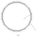
Fig. 2 is a cross-sectional diagram of a packer in the embodiment of the present invention; -
Fig. 3 is a structural schematic diagram of a segment of the packer in the embodiment of the present invention; -
Fig. 4 is another structural schematic diagram of a segment of the packer in the embodiment of the present invention; -
Fig. 5 is a structural schematic diagram of a composite packer in the embodiment of the present invention. - In the
figures: 1 . clamp assembly; 11. segment; 111. bottom plate; 112. fixed plate; 113. mounting plate; 114. limiting plate; 115. end plate; 2. cantilever assembly; 21. cantilever member; 211. fixed end; 212. cantilever end; 3. foundation pile; 4. sleeve; 5. adhesive. - The present invention will be further described below in detail with reference to the drawings in combination with the embodiments.
- As shown in
Fig. 1 , one aspect of the embodiment of the present invention provides a packer, which is configured to pack the bottom of a gap between a foundation pile and a sleeve, comprising: aclamp assembly 1 and acantilever assembly 2. - The
clamp assembly 1 is sleeved on thefoundation pile 3 and connected with the bottom of thesleeve 4; theclamp assembly 1 comprises a plurality ofsegments 11, and thesegments 11 are connected to each other to form an annular structure. - The
cantilever assembly 2 comprises a plurality layers of cantilever units stacked on the inner side of theclamp assembly 1 and in the vertical direction, each cantilever unit comprisescantilever members 21 annularly and densely placed at intervals on the inner side of theclamp assembly 1, eachcantilever member 21 comprises afixed end 211 and acantilever end 212, as shown inFig. 2 , the fixed ends 211 are connected with theclamp assembly 1, the cantilever ends 212 are configured to resist on thefoundation pile 3, and the length value of eachcantilever member 21 is not smaller than the difference value between the inner radius of thesleeve 4 and the outer radius of thefoundation pile 3, which is contribute to thecantilever member 21 to tightly resist on thefoundation pile 3 even after the cantilever, so as to ensure the packing effect of the packer. - Specifically, as shown in
Fig. 3 , eachsegment 11 comprises: abottom plate 111, afixed plate 112, a mountingplate 113 and a limitingplate 114. Anend plate 115 is respectively provided at both ends of thebottom plate 111, and theend plates 115 of twoadjacent segments 11 are fastened in a welding way. As shown inFig. 2 , the embodiment of the present invention adopts 16 segments, which are connected to each other to form an annular structure. The fixedplate 112 is arranged on thebottom plate 111 and connected with thesleeve 4, and can use various conventional connection methods such as bolts, flanges, welding, etc., so the construction is convenient. The mountingplate 113 is provided on thebottom plate 111, and the mountingplate 113 is provided with mounting holes for mounting thecantilever members 21 at intervals along the length direction of thebottom plate 111. The limitingplate 114 is arranged on thebottom plate 111 and configured to limit the movement of thecantilever member 21, so as to prevent thecantilever member 21 from loosening. - Compared with the prior art, the packer in the embodiment of the present invention does not need to be controlled by complicated hydraulic power, has simple structure, convenient construction, and low construction cost. In the process of pile lowering and pile driving, since the stiffness of the
cantilever member 21 is small, the resistance of the packer to thefoundation pile 3 is very small, which will not lead to the phenomenon of pile jamming. Theclamp assembly 1 is not in direct contact with thefoundation pile 3, and thecantilever member 21 has a strong deformation recovery ability, so the packer will not be damaged by thefoundation pile 3, and the ability to adapt to the eccentricity of thefoundation pile 3 is strong. After the pile is lowered, thecantilever member 21 resists on thefoundation pile 3, which preliminarily realizes the isolation of the bottom end of the gap during the process of the pile driving, so it has the function of preventing the coarse-grained sandy soil aroused by the pile driving from entering the gap with the water flow. In the process of grouting (adhesive injection), the adhesive is usually a paste fluid containing graded slurry and well-graded aggregates. The densely arranged cantilever member has a large surface area, and the gap between thecantilever members 21 is very small. Due to the adsorption of the adhesive slurry on the surface of thecantilever member 21 and the clamping of the adhesive aggregate by the gap between thecantilever members 21, the densely arrangedcantilever members 21 form a whole under the action of the adhesive, so that the rigidity is improved, which can effectively prevent the slurry from leaking. - In addition, the
clamp assembly 1 is connected with thesleeve 4, and thecantilever member 21 is in a deformable state of the cantilever, which can prevent parts with high rigidity of theclamp assembly 1 from being immersed in the range of the pile hole of thefoundation pile 3, and the packer as a whole will not hinder the pile lowering and driving operations, or cause the phenomenon of pile jamming, and can further prevent the packer from being damaged during the pile lowering and pile driving operations. - As a preferred embodiment, as shown in
Fig. 3 , thecantilever member 21 is a single steel wire, thefixed end 211 of the single steel wire is provided with an upsetting head, and the size of the upsetting head is larger than that of the mounting hole. As shown inFig. 4 , thecantilever member 21 can further be a U-shaped steel wire, and thefixed end 211 of the U-shaped steel wire is penetrated and fixed on two mounting holes. The surface of the single steel wire or the U-shaped steel wire is painted with a paint layer to prevent seawater corrosion. Further, thecantilever member 21 is a nylon wire or a composite member of steel wire and rubber. - As shown in
Fig. 5 , another aspect of the embodiment of the present invention further provides a composite packer, which is configured to pack the bottom of a gap between a foundation pile and a sleeve, comprising a plurality of the packers in the above-mentioned embodiment, the plurality of the packers are stacked in a vertical direction and connected with the bottom of thesleeve 4, and the packing effect is increased through superimposing a plurality of the packers. - As shown in
Fig. 1 , another aspect of the embodiment of the present invention further provides a foundation pile structure, comprising: afoundation pile 3, asleeve 4 and a packer. Thesleeve 4 is sleeved on thefoundation pile 3, a gap is reserved between thesleeve 4 and thefoundation pile 3, and an adhesive 5 is filled in the gap. - The packer is configured to pack the bottom of the gap between the
foundation pile 3 and thesleeve 4, and the packer comprises aclamp assembly 1 and acantilever assembly 2. - The
clamp assembly 1 is sleeved on thefoundation pile 3 and connected with the bottom of thesleeve 4; theclamp assembly 1 comprises a plurality ofsegments 11, and thesegments 11 are connected to each other to form an annular structure. - The
cantilever assembly 2 comprises a plurality layers of cantilever units stacked on the inner side of theclamp assembly 1 and in the vertical direction, each cantilever unit comprisescantilever members 21 annularly and densely placed at intervals on the inner side of theclamp assembly 1, eachcantilever member 21 comprises afixed end 211 and acantilever end 212, as shown inFig. 2 , the fixed ends 211 are connected with theclamp assembly 1, the cantilever ends 212 are configured to resist on thefoundation pile 3, and the length value of eachcantilever member 21 is not smaller than the difference value between the inner radius of thesleeve 4 and the outer radius of thefoundation pile 3, which is contribute to thecantilever member 21 to tightly resist on thefoundation pile 3 even after the cantilever, so as to ensure the packing effect of the packer. - Compared with the prior art, the foundation pile structure in the embodiment of the present invention does not need to be controlled by complicated hydraulic power, has simple structure, convenient construction, and low construction cost. In the process of pile lowering and pile driving, since the stiffness of the
cantilever member 21 is small, the resistance of the packer to thefoundation pile 3 is very small, which will not lead to the phenomenon of pile jamming. Theclamp assembly 1 is not in direct contact with thefoundation pile 3, and thecantilever member 21 has a strong deformation recovery ability, so the packer will not be damaged by thefoundation pile 3, and the ability to adapt to the eccentricity of thefoundation pile 3 is strong. After the pile is lowered, thecantilever member 21 resists on thefoundation pile 3, which preliminarily realizes the isolation of the bottom end of the gap during the process of the pile driving, so it has the function of preventing the coarse-grained sandy soil aroused by the pile driving from entering the gap with the water flow. In the process of grouting (adhesive injection), the adhesive is usually a paste fluid containing graded slurry and well-graded aggregates. The densely arranged cantilever member has a large surface area, and the gap between thecantilever members 21 is very small. Due to the adsorption of the adhesive slurry on the surface of thecantilever member 21 and the clamping of the adhesive aggregate by the gap between thecantilever members 21, the densely arrangedcantilever members 21 form a whole under the action of the adhesive, so that the rigidity is improved, which can effectively prevent the slurry from leaking.
Claims (4)
- A packer, which is configured to pack the bottom of a gap between a foundation pile (3) and a sleeve (4), comprising:a clamp assembly (1), which can be sleeved on the foundation pile (3) and is connectable with the bottom of the sleeve (4); anda cantilever assembly (2), which comprises a plurality layers of cantilever units stacked on the inner side of the clamp assembly (1) and in the vertical direction, each cantilever unit comprises cantilever members (21) annularly and densely placed at intervals on the inner side of the clamp assembly (1), each cantilever member (21) comprises a fixed end (211) and a cantilever end (212), the fixed ends (211) are connected with the clamp assembly (1), the cantilever ends (212) are configured to resist on the foundation pile (3), and wherein in use the length value of each cantilever member (21) is not smaller than the difference value between the inner radius of the sleeve (4) and the outer radius of the foundation pile (3);characterized in thatthe clamp assembly (1) comprises a plurality of segments (11), and the segments (11) are connected to each other to form an annular structure;wherein each segment (11) comprises:a bottom plate (111), which is provided with an end plate (115) at both ends;a fixed plate (112), which is arranged on the bottom plate (111), and the fixed plate (112) is connectable with the sleeve (4);a mounting plate (113), which is arranged on the bottom plate (111), and the mounting plate (113) is provided with mounting holes for mounting the cantilever members (21) at intervals along the length direction of the bottom plate (111): anda limiting plate (114), which is arranged on the bottom plate (111), and the limiting plate (114) is configured to limit the movement of the cantilever members (21);wherein the cantilever member (21) is a single steel wire, the fixed end (211) of the single steel wire is provided with an upsetting head, and the size of the upsetting head is larger than that of the mounting hole orwherein the cantilever member (21) is a U-shaped steel wire, and the fixed end (211) of the U-shaped steel wire is penetrated and fixed on two mounting holes;wherein the surface of the cantilever member (21) is painted with paint or grease;wherein optionally the cantilever member (21) is nylon wire or a composite member of steel wire and rubber.
- The packer according to claim 1, wherein the end plates (115) of two adjacent segments (11) are fastened in a welding way.
- A composite packer comprising a plurality of the packers according to claim 1, the composite packer being configured to pack the bottom of a gap between a foundation pile (3) and a sleeve (4), , and the plurality of the packers are stacked in a vertical direction and are connectable with the bottom of the sleeve (4).
- A foundation pile structure with a packer according to claim 1, the foundation pile structure comprising:a foundation pile (3);a sleeve (4), which is sleeved on the foundation pile (3); wherein a gap is reserved between the sleeve (4) and the foundation pile (3), and an adhesive (5) is filled in the gap.
Applications Claiming Priority (2)
| Application Number | Priority Date | Filing Date | Title |
|---|---|---|---|
| CN201911046170.2A CN110747885B (en) | 2019-10-30 | 2019-10-30 | Packer and foundation pile structure |
| PCT/CN2020/091013 WO2021082405A1 (en) | 2019-10-30 | 2020-05-19 | Packer and pile foundation structure |
Publications (3)
| Publication Number | Publication Date |
|---|---|
| EP3913145A1 EP3913145A1 (en) | 2021-11-24 |
| EP3913145A4 EP3913145A4 (en) | 2022-10-26 |
| EP3913145B1 true EP3913145B1 (en) | 2024-07-17 |
Family
ID=69281247
Family Applications (1)
| Application Number | Title | Priority Date | Filing Date |
|---|---|---|---|
| EP20880647.1A Active EP3913145B1 (en) | 2019-10-30 | 2020-05-19 | Packer and pile foundation structure |
Country Status (3)
| Country | Link |
|---|---|
| EP (1) | EP3913145B1 (en) |
| CN (1) | CN110747885B (en) |
| WO (1) | WO2021082405A1 (en) |
Families Citing this family (6)
| Publication number | Priority date | Publication date | Assignee | Title |
|---|---|---|---|---|
| CN110747885B (en) * | 2019-10-30 | 2021-02-09 | 中铁大桥勘测设计院集团有限公司 | Packer and foundation pile structure |
| CN111560936B (en) * | 2020-07-13 | 2020-09-25 | 东营金联建筑工程有限公司 | Umbrella-shaped self-opening type ocean engineering pile pipe packer |
| CN114561949B (en) * | 2022-03-18 | 2024-05-24 | 四川华远建设工程有限公司 | Pile sealing device of improved anchor rod static pressure pile |
| CN114575365A (en) * | 2022-04-18 | 2022-06-03 | 广西航务建设工程有限公司 | Novel cofferdam structure for construction of tie beam in water and construction method thereof |
| WO2024086859A1 (en) * | 2022-10-19 | 2024-04-25 | Wekaba Engineering (Pty) Ltd | A sealing system |
| CN119177604B (en) * | 2024-11-07 | 2025-03-21 | 中国电建集团江西省电力设计院有限公司 | An assembled pier structure and construction method suitable for offshore wind turbine transportation |
Family Cites Families (19)
| Publication number | Priority date | Publication date | Assignee | Title |
|---|---|---|---|---|
| US930974A (en) * | 1908-12-24 | 1909-08-10 | Frederick A Koetitz | Fitting for concrete casings. |
| US954973A (en) * | 1909-06-29 | 1910-04-12 | Frederick A Koetitz | Fitting for pile-casings. |
| JP3676086B2 (en) * | 1998-07-22 | 2005-07-27 | 三菱重工業株式会社 | Steel pipe pile foundation |
| CN2521257Y (en) * | 2002-01-25 | 2002-11-20 | 胜利油田胜利石油化工建设有限责任公司 | Offshore platform tremie frame ring chamber packer |
| GB2433540A (en) * | 2005-12-22 | 2007-06-27 | Martin Hardy | Brush seal for grouting annuli |
| JP5708982B2 (en) * | 2010-10-04 | 2015-04-30 | 清水建設株式会社 | Leakage prevention structure for filled concrete |
| EP2769023A1 (en) * | 2011-10-20 | 2014-08-27 | Crux Products Limited | Monopile transition piece |
| DK2672016T3 (en) * | 2012-06-04 | 2018-04-16 | Innogy Se | Grout seal and method for grouting an annular space between two foundation elements in an offshore structure |
| CN102966117B (en) * | 2012-11-28 | 2015-06-03 | 华南理工大学 | Device for coating bridge underwater pile with concrete |
| GB2524054A (en) * | 2014-03-13 | 2015-09-16 | Marine Current Turbines Ltd | Connector |
| US9970171B2 (en) * | 2014-08-04 | 2018-05-15 | James Lee | Passive grout seal |
| CN204530669U (en) * | 2015-04-15 | 2015-08-05 | 衡水橡胶股份有限公司 | Self-sealing packer |
| CN206128105U (en) * | 2016-08-31 | 2017-04-26 | 朱荣华 | A split lap joint grouting sealing ring |
| CN208717896U (en) * | 2018-07-31 | 2019-04-09 | 东营华晏石油技术有限公司 | A kind of ocean engineering self-closing pile pipe packer |
| CN108708686A (en) * | 2018-08-21 | 2018-10-26 | 天津熙盛科技发展有限公司 | A kind of passive type has the underwater packer of diminution gap function |
| CN109208607B (en) * | 2018-11-06 | 2021-04-20 | 江苏龙源振华海洋工程有限公司 | Grouting plugging process for jacket of offshore booster station |
| CN110241826A (en) * | 2019-07-01 | 2019-09-17 | 中交港湾(上海)科技有限公司 | Underwater Grouting Construction System and Construction Method of Straight Pile Outer Jacket with Pile-First Method |
| CN110747885B (en) * | 2019-10-30 | 2021-02-09 | 中铁大桥勘测设计院集团有限公司 | Packer and foundation pile structure |
| CN110761192B (en) * | 2019-10-30 | 2021-07-06 | 中铁大桥勘测设计院集团有限公司 | Caisson pile foundation and construction method thereof |
-
2019
- 2019-10-30 CN CN201911046170.2A patent/CN110747885B/en active Active
-
2020
- 2020-05-19 WO PCT/CN2020/091013 patent/WO2021082405A1/en not_active Ceased
- 2020-05-19 EP EP20880647.1A patent/EP3913145B1/en active Active
Also Published As
| Publication number | Publication date |
|---|---|
| CN110747885B (en) | 2021-02-09 |
| EP3913145A4 (en) | 2022-10-26 |
| EP3913145A1 (en) | 2021-11-24 |
| CN110747885A (en) | 2020-02-04 |
| WO2021082405A1 (en) | 2021-05-06 |
Similar Documents
| Publication | Publication Date | Title |
|---|---|---|
| EP3913145A1 (en) | Packer and pile foundation structure | |
| CN106223341B (en) | Marine large diameter steel pipe pile slip casting around pile device and its construction method | |
| CN108729873B (en) | Tandem compression packer | |
| US12612837B2 (en) | Inflatable active packer | |
| CN101215837A (en) | Rapid plugging device for deep foundation pit dewatering well | |
| CN118065412B (en) | High-flow water burst plugging method for side wall of foundation pit | |
| CN105133661A (en) | Inflatable packer based on undersea pile leg | |
| CN104234064A (en) | Bridge pier cofferdam reinforcing structure and constructing method thereof | |
| CN103572770A (en) | Pile box hydraulic structure object and building method thereof | |
| CN110093908B (en) | Tower packer for packing jacket cement paste | |
| CN204530669U (en) | Self-sealing packer | |
| CN210151696U (en) | Tower packer for packing conduit frame cement paste | |
| CN104859809A (en) | Self-enclosed packer | |
| CN214194494U (en) | Equipment for preventing concrete material from flowing around during construction of diaphragm wall for isolating river water seepage | |
| CN118727718B (en) | Drilling bored concrete pile and high-pressure jet grouting pile integrated device and method under complex geological conditions | |
| JP5339771B2 (en) | Reinforcement method for columnar structures such as piers | |
| CN110906102B (en) | Emergent accuse oil device under water | |
| CN107975127A (en) | The outer antipriming of vertical jacking | |
| GB2433540A (en) | Brush seal for grouting annuli | |
| CN113152451B (en) | A fixed cylinder for preventing pile foundation pit from collapsing and expanding its diameter | |
| CN115030230A (en) | Pile-first type slurry filling sealing packer and sealing method | |
| CN114525721A (en) | Inland river gravity type trestle wharf in high-intensity area and construction equipment thereof | |
| CN204623783U (en) | Self-closed type excluder | |
| CN222810021U (en) | Integrated grouting device for the side and end of steel pipe piles | |
| CA2959106C (en) | Method and apparatus for access and remediation of hydrocarbon storage tanks |
Legal Events
| Date | Code | Title | Description |
|---|---|---|---|
| STAA | Information on the status of an ep patent application or granted ep patent |
Free format text: STATUS: THE INTERNATIONAL PUBLICATION HAS BEEN MADE |
|
| PUAI | Public reference made under article 153(3) epc to a published international application that has entered the european phase |
Free format text: ORIGINAL CODE: 0009012 |
|
| STAA | Information on the status of an ep patent application or granted ep patent |
Free format text: STATUS: REQUEST FOR EXAMINATION WAS MADE |
|
| 17P | Request for examination filed |
Effective date: 20210817 |
|
| AK | Designated contracting states |
Kind code of ref document: A1 Designated state(s): AL AT BE BG CH CY CZ DE DK EE ES FI FR GB GR HR HU IE IS IT LI LT LU LV MC MK MT NL NO PL PT RO RS SE SI SK SM TR |
|
| REG | Reference to a national code |
Ref legal event code: R079 Free format text: PREVIOUS MAIN CLASS: E02D0027520000 Ref country code: DE Ref legal event code: R079 Ref document number: 602020034288 Country of ref document: DE Free format text: PREVIOUS MAIN CLASS: E02D0027520000 Ipc: E02D0005600000 |
|
| A4 | Supplementary search report drawn up and despatched |
Effective date: 20220926 |
|
| RIC1 | Information provided on ipc code assigned before grant |
Ipc: E02B 17/00 20060101ALI20220920BHEP Ipc: E02D 15/06 20060101ALI20220920BHEP Ipc: E02D 5/40 20060101ALI20220920BHEP Ipc: E02D 31/04 20060101ALI20220920BHEP Ipc: E02D 15/08 20060101ALI20220920BHEP Ipc: E02D 27/52 20060101ALI20220920BHEP Ipc: E02D 13/00 20060101ALI20220920BHEP Ipc: E02D 5/22 20060101ALI20220920BHEP Ipc: E02D 5/60 20060101AFI20220920BHEP |
|
| DAV | Request for validation of the european patent (deleted) | ||
| DAX | Request for extension of the european patent (deleted) | ||
| GRAP | Despatch of communication of intention to grant a patent |
Free format text: ORIGINAL CODE: EPIDOSNIGR1 |
|
| STAA | Information on the status of an ep patent application or granted ep patent |
Free format text: STATUS: GRANT OF PATENT IS INTENDED |
|
| INTG | Intention to grant announced |
Effective date: 20240314 |
|
| GRAS | Grant fee paid |
Free format text: ORIGINAL CODE: EPIDOSNIGR3 |
|
| GRAA | (expected) grant |
Free format text: ORIGINAL CODE: 0009210 |
|
| STAA | Information on the status of an ep patent application or granted ep patent |
Free format text: STATUS: THE PATENT HAS BEEN GRANTED |
|
| AK | Designated contracting states |
Kind code of ref document: B1 Designated state(s): AL AT BE BG CH CY CZ DE DK EE ES FI FR GB GR HR HU IE IS IT LI LT LU LV MC MK MT NL NO PL PT RO RS SE SI SK SM TR |
|
| REG | Reference to a national code |
Ref country code: CH Ref legal event code: EP |
|
| REG | Reference to a national code |
Ref country code: DE Ref legal event code: R096 Ref document number: 602020034288 Country of ref document: DE |
|
| REG | Reference to a national code |
Ref country code: IE Ref legal event code: FG4D |
|
| REG | Reference to a national code |
Ref country code: LT Ref legal event code: MG9D |
|
| REG | Reference to a national code |
Ref country code: NL Ref legal event code: MP Effective date: 20240717 |
|
| PG25 | Lapsed in a contracting state [announced via postgrant information from national office to epo] |
Ref country code: PT Free format text: LAPSE BECAUSE OF FAILURE TO SUBMIT A TRANSLATION OF THE DESCRIPTION OR TO PAY THE FEE WITHIN THE PRESCRIBED TIME-LIMIT Effective date: 20241118 |
|
| REG | Reference to a national code |
Ref country code: AT Ref legal event code: MK05 Ref document number: 1704246 Country of ref document: AT Kind code of ref document: T Effective date: 20240717 |
|
| PG25 | Lapsed in a contracting state [announced via postgrant information from national office to epo] |
Ref country code: NL Free format text: LAPSE BECAUSE OF FAILURE TO SUBMIT A TRANSLATION OF THE DESCRIPTION OR TO PAY THE FEE WITHIN THE PRESCRIBED TIME-LIMIT Effective date: 20240717 |
|
| PG25 | Lapsed in a contracting state [announced via postgrant information from national office to epo] |
Ref country code: PT Free format text: LAPSE BECAUSE OF FAILURE TO SUBMIT A TRANSLATION OF THE DESCRIPTION OR TO PAY THE FEE WITHIN THE PRESCRIBED TIME-LIMIT Effective date: 20241118 Ref country code: NL Free format text: LAPSE BECAUSE OF FAILURE TO SUBMIT A TRANSLATION OF THE DESCRIPTION OR TO PAY THE FEE WITHIN THE PRESCRIBED TIME-LIMIT Effective date: 20240717 |
|
| PG25 | Lapsed in a contracting state [announced via postgrant information from national office to epo] |
Ref country code: NO Free format text: LAPSE BECAUSE OF FAILURE TO SUBMIT A TRANSLATION OF THE DESCRIPTION OR TO PAY THE FEE WITHIN THE PRESCRIBED TIME-LIMIT Effective date: 20241017 |
|
| PG25 | Lapsed in a contracting state [announced via postgrant information from national office to epo] |
Ref country code: GR Free format text: LAPSE BECAUSE OF FAILURE TO SUBMIT A TRANSLATION OF THE DESCRIPTION OR TO PAY THE FEE WITHIN THE PRESCRIBED TIME-LIMIT Effective date: 20241018 Ref country code: FI Free format text: LAPSE BECAUSE OF FAILURE TO SUBMIT A TRANSLATION OF THE DESCRIPTION OR TO PAY THE FEE WITHIN THE PRESCRIBED TIME-LIMIT Effective date: 20240717 Ref country code: PL Free format text: LAPSE BECAUSE OF FAILURE TO SUBMIT A TRANSLATION OF THE DESCRIPTION OR TO PAY THE FEE WITHIN THE PRESCRIBED TIME-LIMIT Effective date: 20240717 |
|
| PG25 | Lapsed in a contracting state [announced via postgrant information from national office to epo] |
Ref country code: BG Free format text: LAPSE BECAUSE OF FAILURE TO SUBMIT A TRANSLATION OF THE DESCRIPTION OR TO PAY THE FEE WITHIN THE PRESCRIBED TIME-LIMIT Effective date: 20240717 |
|
| PG25 | Lapsed in a contracting state [announced via postgrant information from national office to epo] |
Ref country code: LV Free format text: LAPSE BECAUSE OF FAILURE TO SUBMIT A TRANSLATION OF THE DESCRIPTION OR TO PAY THE FEE WITHIN THE PRESCRIBED TIME-LIMIT Effective date: 20240717 |
|
| PG25 | Lapsed in a contracting state [announced via postgrant information from national office to epo] |
Ref country code: IS Free format text: LAPSE BECAUSE OF FAILURE TO SUBMIT A TRANSLATION OF THE DESCRIPTION OR TO PAY THE FEE WITHIN THE PRESCRIBED TIME-LIMIT Effective date: 20241117 Ref country code: AT Free format text: LAPSE BECAUSE OF FAILURE TO SUBMIT A TRANSLATION OF THE DESCRIPTION OR TO PAY THE FEE WITHIN THE PRESCRIBED TIME-LIMIT Effective date: 20240717 |
|
| PG25 | Lapsed in a contracting state [announced via postgrant information from national office to epo] |
Ref country code: HR Free format text: LAPSE BECAUSE OF FAILURE TO SUBMIT A TRANSLATION OF THE DESCRIPTION OR TO PAY THE FEE WITHIN THE PRESCRIBED TIME-LIMIT Effective date: 20240717 |
|
| PG25 | Lapsed in a contracting state [announced via postgrant information from national office to epo] |
Ref country code: RS Free format text: LAPSE BECAUSE OF FAILURE TO SUBMIT A TRANSLATION OF THE DESCRIPTION OR TO PAY THE FEE WITHIN THE PRESCRIBED TIME-LIMIT Effective date: 20241017 Ref country code: ES Free format text: LAPSE BECAUSE OF FAILURE TO SUBMIT A TRANSLATION OF THE DESCRIPTION OR TO PAY THE FEE WITHIN THE PRESCRIBED TIME-LIMIT Effective date: 20240717 |
|
| PG25 | Lapsed in a contracting state [announced via postgrant information from national office to epo] |
Ref country code: RS Free format text: LAPSE BECAUSE OF FAILURE TO SUBMIT A TRANSLATION OF THE DESCRIPTION OR TO PAY THE FEE WITHIN THE PRESCRIBED TIME-LIMIT Effective date: 20241017 Ref country code: PL Free format text: LAPSE BECAUSE OF FAILURE TO SUBMIT A TRANSLATION OF THE DESCRIPTION OR TO PAY THE FEE WITHIN THE PRESCRIBED TIME-LIMIT Effective date: 20240717 Ref country code: NO Free format text: LAPSE BECAUSE OF FAILURE TO SUBMIT A TRANSLATION OF THE DESCRIPTION OR TO PAY THE FEE WITHIN THE PRESCRIBED TIME-LIMIT Effective date: 20241017 Ref country code: LV Free format text: LAPSE BECAUSE OF FAILURE TO SUBMIT A TRANSLATION OF THE DESCRIPTION OR TO PAY THE FEE WITHIN THE PRESCRIBED TIME-LIMIT Effective date: 20240717 Ref country code: IS Free format text: LAPSE BECAUSE OF FAILURE TO SUBMIT A TRANSLATION OF THE DESCRIPTION OR TO PAY THE FEE WITHIN THE PRESCRIBED TIME-LIMIT Effective date: 20241117 Ref country code: HR Free format text: LAPSE BECAUSE OF FAILURE TO SUBMIT A TRANSLATION OF THE DESCRIPTION OR TO PAY THE FEE WITHIN THE PRESCRIBED TIME-LIMIT Effective date: 20240717 Ref country code: GR Free format text: LAPSE BECAUSE OF FAILURE TO SUBMIT A TRANSLATION OF THE DESCRIPTION OR TO PAY THE FEE WITHIN THE PRESCRIBED TIME-LIMIT Effective date: 20241018 Ref country code: FI Free format text: LAPSE BECAUSE OF FAILURE TO SUBMIT A TRANSLATION OF THE DESCRIPTION OR TO PAY THE FEE WITHIN THE PRESCRIBED TIME-LIMIT Effective date: 20240717 Ref country code: ES Free format text: LAPSE BECAUSE OF FAILURE TO SUBMIT A TRANSLATION OF THE DESCRIPTION OR TO PAY THE FEE WITHIN THE PRESCRIBED TIME-LIMIT Effective date: 20240717 Ref country code: BG Free format text: LAPSE BECAUSE OF FAILURE TO SUBMIT A TRANSLATION OF THE DESCRIPTION OR TO PAY THE FEE WITHIN THE PRESCRIBED TIME-LIMIT Effective date: 20240717 Ref country code: AT Free format text: LAPSE BECAUSE OF FAILURE TO SUBMIT A TRANSLATION OF THE DESCRIPTION OR TO PAY THE FEE WITHIN THE PRESCRIBED TIME-LIMIT Effective date: 20240717 |
|
| PG25 | Lapsed in a contracting state [announced via postgrant information from national office to epo] |
Ref country code: DK Free format text: LAPSE BECAUSE OF FAILURE TO SUBMIT A TRANSLATION OF THE DESCRIPTION OR TO PAY THE FEE WITHIN THE PRESCRIBED TIME-LIMIT Effective date: 20240717 Ref country code: RO Free format text: LAPSE BECAUSE OF FAILURE TO SUBMIT A TRANSLATION OF THE DESCRIPTION OR TO PAY THE FEE WITHIN THE PRESCRIBED TIME-LIMIT Effective date: 20240717 Ref country code: SM Free format text: LAPSE BECAUSE OF FAILURE TO SUBMIT A TRANSLATION OF THE DESCRIPTION OR TO PAY THE FEE WITHIN THE PRESCRIBED TIME-LIMIT Effective date: 20240717 |
|
| REG | Reference to a national code |
Ref country code: DE Ref legal event code: R097 Ref document number: 602020034288 Country of ref document: DE |
|
| PG25 | Lapsed in a contracting state [announced via postgrant information from national office to epo] |
Ref country code: EE Free format text: LAPSE BECAUSE OF FAILURE TO SUBMIT A TRANSLATION OF THE DESCRIPTION OR TO PAY THE FEE WITHIN THE PRESCRIBED TIME-LIMIT Effective date: 20240717 |
|
| PG25 | Lapsed in a contracting state [announced via postgrant information from national office to epo] |
Ref country code: CZ Free format text: LAPSE BECAUSE OF FAILURE TO SUBMIT A TRANSLATION OF THE DESCRIPTION OR TO PAY THE FEE WITHIN THE PRESCRIBED TIME-LIMIT Effective date: 20240717 |
|
| PG25 | Lapsed in a contracting state [announced via postgrant information from national office to epo] |
Ref country code: SK Free format text: LAPSE BECAUSE OF FAILURE TO SUBMIT A TRANSLATION OF THE DESCRIPTION OR TO PAY THE FEE WITHIN THE PRESCRIBED TIME-LIMIT Effective date: 20240717 |
|
| PLBE | No opposition filed within time limit |
Free format text: ORIGINAL CODE: 0009261 |
|
| STAA | Information on the status of an ep patent application or granted ep patent |
Free format text: STATUS: NO OPPOSITION FILED WITHIN TIME LIMIT |
|
| 26N | No opposition filed |
Effective date: 20250422 |
|
| PG25 | Lapsed in a contracting state [announced via postgrant information from national office to epo] |
Ref country code: SE Free format text: LAPSE BECAUSE OF FAILURE TO SUBMIT A TRANSLATION OF THE DESCRIPTION OR TO PAY THE FEE WITHIN THE PRESCRIBED TIME-LIMIT Effective date: 20240717 |
|
| REG | Reference to a national code |
Ref country code: DE Ref legal event code: R119 Ref document number: 602020034288 Country of ref document: DE |
|
| REG | Reference to a national code |
Ref country code: CH Ref legal event code: H13 Free format text: ST27 STATUS EVENT CODE: U-0-0-H10-H13 (AS PROVIDED BY THE NATIONAL OFFICE) Effective date: 20251223 |
|
| PG25 | Lapsed in a contracting state [announced via postgrant information from national office to epo] |
Ref country code: LU Free format text: LAPSE BECAUSE OF NON-PAYMENT OF DUE FEES Effective date: 20250519 |
|
| PG25 | Lapsed in a contracting state [announced via postgrant information from national office to epo] |
Ref country code: CH Free format text: LAPSE BECAUSE OF NON-PAYMENT OF DUE FEES Effective date: 20250531 |
|
| GBPC | Gb: european patent ceased through non-payment of renewal fee |
Effective date: 20250519 |
|
| PG25 | Lapsed in a contracting state [announced via postgrant information from national office to epo] |
Ref country code: IT Free format text: LAPSE BECAUSE OF FAILURE TO SUBMIT A TRANSLATION OF THE DESCRIPTION OR TO PAY THE FEE WITHIN THE PRESCRIBED TIME-LIMIT Effective date: 20240717 |
|
| REG | Reference to a national code |
Ref country code: BE Ref legal event code: MM Effective date: 20250531 |
|
| PG25 | Lapsed in a contracting state [announced via postgrant information from national office to epo] |
Ref country code: MC Free format text: LAPSE BECAUSE OF FAILURE TO SUBMIT A TRANSLATION OF THE DESCRIPTION OR TO PAY THE FEE WITHIN THE PRESCRIBED TIME-LIMIT Effective date: 20240717 |
|
| PG25 | Lapsed in a contracting state [announced via postgrant information from national office to epo] |
Ref country code: GB Free format text: LAPSE BECAUSE OF NON-PAYMENT OF DUE FEES Effective date: 20250519 |
|
| PG25 | Lapsed in a contracting state [announced via postgrant information from national office to epo] |
Ref country code: IE Free format text: LAPSE BECAUSE OF NON-PAYMENT OF DUE FEES Effective date: 20250519 Ref country code: DE Free format text: LAPSE BECAUSE OF NON-PAYMENT OF DUE FEES Effective date: 20251202 |
|
| PG25 | Lapsed in a contracting state [announced via postgrant information from national office to epo] |
Ref country code: BE Free format text: LAPSE BECAUSE OF NON-PAYMENT OF DUE FEES Effective date: 20250531 |
|
| PG25 | Lapsed in a contracting state [announced via postgrant information from national office to epo] |
Ref country code: FR Free format text: LAPSE BECAUSE OF NON-PAYMENT OF DUE FEES Effective date: 20250531 |