EP3912862A2 - Vehicle lamp and headlamp assembly - Google Patents
Vehicle lamp and headlamp assembly Download PDFInfo
- Publication number
- EP3912862A2 EP3912862A2 EP21175409.8A EP21175409A EP3912862A2 EP 3912862 A2 EP3912862 A2 EP 3912862A2 EP 21175409 A EP21175409 A EP 21175409A EP 3912862 A2 EP3912862 A2 EP 3912862A2
- Authority
- EP
- European Patent Office
- Prior art keywords
- light
- light source
- vehicle
- lens
- exit
- Prior art date
- Legal status (The legal status is an assumption and is not a legal conclusion. Google has not performed a legal analysis and makes no representation as to the accuracy of the status listed.)
- Granted
Links
Images




Classifications
-
- B—PERFORMING OPERATIONS; TRANSPORTING
- B60—VEHICLES IN GENERAL
- B60Q—ARRANGEMENT OF SIGNALLING OR LIGHTING DEVICES, THE MOUNTING OR SUPPORTING THEREOF OR CIRCUITS THEREFOR, FOR VEHICLES IN GENERAL
- B60Q1/00—Arrangement of optical signalling or lighting devices, the mounting or supporting thereof or circuits therefor
- B60Q1/0029—Spatial arrangement
- B60Q1/0035—Spatial arrangement relative to the vehicle
-
- B—PERFORMING OPERATIONS; TRANSPORTING
- B60—VEHICLES IN GENERAL
- B60Q—ARRANGEMENT OF SIGNALLING OR LIGHTING DEVICES, THE MOUNTING OR SUPPORTING THEREOF OR CIRCUITS THEREFOR, FOR VEHICLES IN GENERAL
- B60Q1/00—Arrangement of optical signalling or lighting devices, the mounting or supporting thereof or circuits therefor
- B60Q1/0029—Spatial arrangement
- B60Q1/0041—Spatial arrangement of several lamps in relation to each other
-
- B—PERFORMING OPERATIONS; TRANSPORTING
- B60—VEHICLES IN GENERAL
- B60Q—ARRANGEMENT OF SIGNALLING OR LIGHTING DEVICES, THE MOUNTING OR SUPPORTING THEREOF OR CIRCUITS THEREFOR, FOR VEHICLES IN GENERAL
- B60Q1/00—Arrangement of optical signalling or lighting devices, the mounting or supporting thereof or circuits therefor
- B60Q1/26—Arrangement of optical signalling or lighting devices, the mounting or supporting thereof or circuits therefor the devices being primarily intended to indicate the vehicle, or parts thereof, or to give signals, to other traffic
- B60Q1/2607—Arrangement of optical signalling or lighting devices, the mounting or supporting thereof or circuits therefor the devices being primarily intended to indicate the vehicle, or parts thereof, or to give signals, to other traffic comprising at least two indicating lamps
-
- B—PERFORMING OPERATIONS; TRANSPORTING
- B60—VEHICLES IN GENERAL
- B60Q—ARRANGEMENT OF SIGNALLING OR LIGHTING DEVICES, THE MOUNTING OR SUPPORTING THEREOF OR CIRCUITS THEREFOR, FOR VEHICLES IN GENERAL
- B60Q1/00—Arrangement of optical signalling or lighting devices, the mounting or supporting thereof or circuits therefor
- B60Q1/26—Arrangement of optical signalling or lighting devices, the mounting or supporting thereof or circuits therefor the devices being primarily intended to indicate the vehicle, or parts thereof, or to give signals, to other traffic
- B60Q1/34—Arrangement of optical signalling or lighting devices, the mounting or supporting thereof or circuits therefor the devices being primarily intended to indicate the vehicle, or parts thereof, or to give signals, to other traffic for indicating change of drive direction
-
- B—PERFORMING OPERATIONS; TRANSPORTING
- B60—VEHICLES IN GENERAL
- B60R—VEHICLES, VEHICLE FITTINGS, OR VEHICLE PARTS, NOT OTHERWISE PROVIDED FOR
- B60R19/00—Wheel guards; Radiator guards, e.g. grilles; Obstruction removers; Fittings damping bouncing force in collisions
- B60R19/52—Radiator or grille guards ; Radiator grilles
-
- F—MECHANICAL ENGINEERING; LIGHTING; HEATING; WEAPONS; BLASTING
- F21—LIGHTING
- F21S—NON-PORTABLE LIGHTING DEVICES; SYSTEMS THEREOF; VEHICLE LIGHTING DEVICES SPECIALLY ADAPTED FOR VEHICLE EXTERIORS
- F21S43/00—Signalling devices specially adapted for vehicle exteriors, e.g. brake lamps, direction indicator lights or reversing lights
- F21S43/10—Signalling devices specially adapted for vehicle exteriors, e.g. brake lamps, direction indicator lights or reversing lights characterised by the light source
- F21S43/13—Signalling devices specially adapted for vehicle exteriors, e.g. brake lamps, direction indicator lights or reversing lights characterised by the light source characterised by the type of light source
- F21S43/14—Light emitting diodes [LED]
-
- F—MECHANICAL ENGINEERING; LIGHTING; HEATING; WEAPONS; BLASTING
- F21—LIGHTING
- F21S—NON-PORTABLE LIGHTING DEVICES; SYSTEMS THEREOF; VEHICLE LIGHTING DEVICES SPECIALLY ADAPTED FOR VEHICLE EXTERIORS
- F21S43/00—Signalling devices specially adapted for vehicle exteriors, e.g. brake lamps, direction indicator lights or reversing lights
- F21S43/20—Signalling devices specially adapted for vehicle exteriors, e.g. brake lamps, direction indicator lights or reversing lights characterised by refractors, transparent cover plates, light guides or filters
- F21S43/235—Light guides
- F21S43/236—Light guides characterised by the shape of the light guide
- F21S43/241—Light guides characterised by the shape of the light guide of complex shape
-
- F—MECHANICAL ENGINEERING; LIGHTING; HEATING; WEAPONS; BLASTING
- F21—LIGHTING
- F21S—NON-PORTABLE LIGHTING DEVICES; SYSTEMS THEREOF; VEHICLE LIGHTING DEVICES SPECIALLY ADAPTED FOR VEHICLE EXTERIORS
- F21S43/00—Signalling devices specially adapted for vehicle exteriors, e.g. brake lamps, direction indicator lights or reversing lights
- F21S43/20—Signalling devices specially adapted for vehicle exteriors, e.g. brake lamps, direction indicator lights or reversing lights characterised by refractors, transparent cover plates, light guides or filters
- F21S43/235—Light guides
- F21S43/242—Light guides characterised by the emission area
- F21S43/243—Light guides characterised by the emission area emitting light from one or more of its extremities
-
- F—MECHANICAL ENGINEERING; LIGHTING; HEATING; WEAPONS; BLASTING
- F21—LIGHTING
- F21S—NON-PORTABLE LIGHTING DEVICES; SYSTEMS THEREOF; VEHICLE LIGHTING DEVICES SPECIALLY ADAPTED FOR VEHICLE EXTERIORS
- F21S43/00—Signalling devices specially adapted for vehicle exteriors, e.g. brake lamps, direction indicator lights or reversing lights
- F21S43/20—Signalling devices specially adapted for vehicle exteriors, e.g. brake lamps, direction indicator lights or reversing lights characterised by refractors, transparent cover plates, light guides or filters
- F21S43/235—Light guides
- F21S43/249—Light guides with two or more light sources being coupled into the light guide
-
- F—MECHANICAL ENGINEERING; LIGHTING; HEATING; WEAPONS; BLASTING
- F21—LIGHTING
- F21S—NON-PORTABLE LIGHTING DEVICES; SYSTEMS THEREOF; VEHICLE LIGHTING DEVICES SPECIALLY ADAPTED FOR VEHICLE EXTERIORS
- F21S43/00—Signalling devices specially adapted for vehicle exteriors, e.g. brake lamps, direction indicator lights or reversing lights
- F21S43/50—Signalling devices specially adapted for vehicle exteriors, e.g. brake lamps, direction indicator lights or reversing lights characterised by aesthetic components not otherwise provided for, e.g. decorative trim, partition walls or covers
-
- B—PERFORMING OPERATIONS; TRANSPORTING
- B60—VEHICLES IN GENERAL
- B60R—VEHICLES, VEHICLE FITTINGS, OR VEHICLE PARTS, NOT OTHERWISE PROVIDED FOR
- B60R19/00—Wheel guards; Radiator guards, e.g. grilles; Obstruction removers; Fittings damping bouncing force in collisions
- B60R19/52—Radiator or grille guards ; Radiator grilles
- B60R2019/525—Radiator grilles
Definitions
- the present disclosure relates to vehicle lamps and headlamp assemblies and relates in particular to a vehicle lamp and a headlamp assembly capable of reducing the size of the light transmitting portion formed on an ornamental panel (e.g., a grille portion).
- an ornamental panel e.g., a grille portion
- German Patent Application No. 10 2013 008 908 discloses a vehicle lamp that includes a light-transmitting portion (e.g., an opening) formed in a grille (a grille frame), and as a light from an illumination device disposed in a housing is transmitted (or passes) through the light-transmitting portion, the light from the illumination device illuminates an area in a target direction without being blocked by the grille.
- a light-transmitting portion e.g., an opening
- a grille a grille frame
- the present disclosure has been made in view of such an issue and is directed to providing a vehicle lamp and a headlamp assembly capable of reducing the size of the light transmitting portion formed on an ornamental panel (e.g., a grille portion).
- an ornamental panel e.g., a grille portion
- a vehicle lamp comprises an ornamental panel including a light-transmitting portion and a non-light-transmitting portion; a lens disposed behind the ornamental panel; and a light source disposed behind the ornamental panel, the light source being configured to emit a light that is to be transmitted sequentially through the lens and the light-transmitting portion and that is to illuminate an area in front of a vehicle and inward in a vehicle-width direction, wherein the lens is configured to condense the light from the light source that is transmitted through the lens, and the light-transmitting portion has a size corresponding to a size of the light from the light source that has been condensed by the lens.
- the size of the light transmitting portion of the decorative panel through which the light from the light source is transmitted can be made smaller corresponding to the light from the condensed light source, compared with the case where the light from the light source is not condensed.
- the lens and the light source may be disposed behind the non-light-transmitting portion of the ornamental panel.
- the lens and the light source may be disposed behind the non-light-transmitting portion of the ornamental panel.
- the light source, the lens, and the light-transmitting portion are disposed in this order toward a front of the vehicle and inward in the vehicle-width direction.
- the ornamental panel the light-transmitting portion
- the light source may include a first light source configured to emit a light of a first color and a second light source configured to emit a light of a second color.
- two lamp functions e.g., a turn lamp function and a position lamp function
- the lens may include a first light-entry portion configured to receive the light from the first light source, a first light-exit portion through which the light from the first light source that has entered through the first light-entry portion exits, a first light-guide portion configured to guide the light from the first light source that has entered through the first light-entry portion to the first light-exit portion and to cause the light to exit through the first light-exit portion, a second light-entry portion configured to receive the light from the second light source, a second light-exit portion through which the light from the second light source that has entered through the second light-entry portion exits, and a second light-guide portion configured to guide the light from the second light source that has entered through the second light-entry portion to the second light-exit portion and to cause the light to exit through the second light-exit portion, the first light-exit portion may be configured to condense the light from the first light source that exits through the first light-exit portion, and the second light-guide portion configured to guide the light
- the ornamental panel may be a member that is physically separate from a grille main body attached to a front end of the vehicle.
- the ornamental panel may be attached to a headlamp assembly, the ornamental panel may be arranged at a position adjacent to the grille body by mounting the headlamp assembly to the front end of the vehicle.
- the ornamental panel may be formed integrally with a grille main body attached to a front end of the vehicle.
- the ornamental panel may be a grille portion constituting a grille along with a grille main body attached to a front end of the vehicle.
- a headlamp assembly comprises; an inward illuminating lamp configured to illuminate at least an area in front of a vehicle and inward in a vehicle-width direction; an outward illuminating lamp configured to illuminate at least an area in front of the vehicle and outward in the vehicle-width direction; a lamp configured to function as a headlamp; and an ornamental panel including a light-transmitting portion and a non-light-transmitting portion, wherein the inward illuminating lamp includes a lens disposed behind the ornamental panel, and a light source disposed behind the ornamental panel, the light source being configured to emit a light that is to be transmitted sequentially through the lens and the light-transmitting portion and that is to illuminate the area in front of the vehicle and inward in the vehicle-width direction, the lens is configured to condense the light from the light source that is transmitted through the lens, and the light-transmitting portion has a size corresponding to a size of the light from the light source that has been condensed by the lens.
- the size of the light transmitting portion of the decorative panel through which the light from the light source is transmitted can be made smaller corresponding to the light from the condensed light source, compared with the case where the light from the light source is not condensed.
- a vehicle lamp and a headlamp assembly capable of reducing the size of the light transmitting portion formed on an ornamental panel (e.g., a grille portion).
- a headlamp assembly 10 that includes a vehicle lamp (an inward illuminating lamp 40) according to an embodiment of the present disclosure will be described with reference to the appended drawings.
- a vehicle lamp an inward illuminating lamp 40
- corresponding constituent elements are given identical reference characters, and duplicate descriptions thereof will be omitted.
- Fig. 1 is a perspective view of the headlamp assembly 10
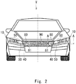
- Fig. 2 is a front view of a vehicle V provided with the headlamp assembly 10.
- the headlamp assembly 10 is provided on each of the right and left sides of a front end of the vehicle V, such as an automobile.
- the headlamp assemblies 10 provided on the right and left sides have horizontally symmetric configurations. Therefore, only the headlamp assembly 10 provided on the left side of the front end of the vehicle V (the left-hand side as facing forward from the vehicle) will be described below as a representative example.
- Fig. 3 is an exploded perspective view of the headlamp assembly 10.
- the headlamp assembly 10 includes an outer lens 20, a housing 30, a first lamp (the inward illuminating lamp 40 and an outward illuminating lamp 50) that functions as a position lamp and as a turn lamp, an inner lens 60, a second lamp 70 that functions as a headlamp, and a grille end portion 80.
- the inward illuminating lamp 40, the inner lens 60, the second lamp 70, and the grille end portion 80 are attached to the outer lens 20.
- the outward illuminating lamp 50 is attached to the housing 30.
- the headlamp assembly 10 illustrated in Fig. 1 is formed by combining the outer lens 20 and the housing 30 to which the aforementioned components attached thereto.
- the inward illuminating lamp 40, the outward illuminating lamp 50, the inner lens 60, and the second lamp 70 are disposed in a lamp room 91 (see Fig. 4 ) formed by the outer lens 20 and the housing 30.
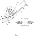
- Fig. 4 is a sectional view taken along the A-A line indicated in Fig. 2 .
- the outer lens 20 is a light-transmissive cover made of a transparent resin, such as acryl or polycarbonate.
- a headlamp assembly 10 is attached to the front end of the vehicle V (see Fig. 2 ). At this time, as shown in FIG 4 , the outer lens 20 is disposed in a state inclined rearward from the inside toward the outward in the vehicle width direction.
- the grille end portion 80 is attached to the outer lens 20.
- the grille end portion 80 is an example of an ornamental panel or a grille portion according to the present disclosure.
- the grille end portion 80 is a member physically separate from a grille main body 90 (see Fig. 2 ).
- the grille main body 90 is, for example, a panel (an ornamental panel provided mainly for decorative purpose) made of a synthetic resin. As illustrated in Fig. 2 , the grille main body 90 is attached to the front end of the vehicle V. Specifically, the grille main body 90 is attached, of the front end of the vehicle V, to an area between the right and left headlamp assemblies 10 provided on the front end of the vehicle V. The grille main body 90 does not include an air passage through which the air for cooling the radiator and so on passes.
- the grille end portion 80 is, for example, a panel (an ornamental panel provided mainly for decorative purpose) made of a synthetic resin.
- the grille end portion 80 is attached to the outer lens 20 (e.g., the inward end of the outer lens 20 in the vehicle-width direction).
- the grille end portion 80 is attached such that the front surface of the grille end portion 80 and the front surface of the outer lens 20 are smoothly continuous (see Fig. 4 ) without any step.
- the grille end portion 80 is located at a position adjacent to the grille main body 90 in a state that the headlamp assembly 10 is attached to the front end of the vehicle V (see Fig. 2 ).
- the grille main body 90 and the grille end portion 80 located at a position adjacent to the grille main body 90 are visually recognized as one grill.
- the grille end portion 80 includes a light-transmitting portion 81 through which light irradiated from the inward illuminating lamp 40 is transmitted and a non-light-transmitting portion 82 through which the light is not transmitted.
- the grill end portion 80 can be formed, for example, by masking a portion of the transparent resin panel corresponding to the light-transmitting portion 81 and painting the other portions with an opaque color (e.g., black).
- the grille end portion 80 can be formed by forming a through-hole in a portion corresponding to the light-transmitting portion 81 with respect to the opaque resin panel (For example, a black panel).
- the through-hole may be closed by a light-transmitting portion such as a transparent resin.
- An accommodating portion 21 in which the inward illuminating lamp 40 is housed is disposed behind the grille end portion 80.
- the accommodating portion 21 is provided, for example, on the outer lens 20 (e.g., the inward end of the outer lens 20 in the vehicle-width direction).
- the accommodating portion 21 is provided with a light-transmitting portion 21a through which light emitted from the inward illuminating lamp 40 disposed in the accommodating portion 21 passes.
- Fig. 5 illustrates an example of an illumination range of the inward illuminating lamp 40 and an illumination range of the outward illuminating lamp 50.
- the inward illuminating lamp 40 illuminates a range ⁇ 1 in front of the vehicle and inward in the vehicle-width direction.
- the inward illuminating lamp 40 is an example of a vehicle lamp according to the present disclosure.
- the inward illuminating lamp 40 is disposed behind the grille end portion 80.
- the inward illuminating lamp 40 is disposed behind the non-light-transmitting portion 82 of the grille end portion 80 in a state of being housed in the accommodating portion 21 provided in the outer lens 20.
- the non-light-transmitting portion 82 is, for example, a portion of the grill end portion 80 between the light-transmitting portion 81 and an outer end 83 of the grill end portion 80 in the vehicle-width direction.
- the inward illuminating lamp 40 includes a turn lamp light source 41, a position lamp light source 42, and an inner lens 43.
- the turn lamp light source 41 is an example of a first light source according to the present disclosure
- the position lamp light source 42 is an example of a second light source according to the present disclosure
- the inner lens 43 is an example of a lens according to the present disclosure.
- the set of the light sources 41 and 42, the inner lens 43, and the light-transmitting portion 81 of the grille end portion 80 are disposed in this order toward the front of the vehicle and inward in the vehicle-width direction.
- the turn lamp light source 41 and the position lamp light source 42 are both mounted on the same surface of a substrate K with a predefined gap provided therebetween in the horizontal direction.
- the turn lamp light source 41 is a semiconductor light-emitting element, such as an LED, that emits an amber light.
- the turn lamp light source 41 has an emission surface (e.g., a rectangular emission surface that measures 1 mm on each side).
- An optical axis AX 41 of the turn lamp light source 41 passes through the center of the emission surface of the turn lamp light source 41 and extends in a direction orthogonal to the emission surface.
- the position lamp light source 42 is a semiconductor light-emitting element, such as an LED, that emits a white light.
- the position lamp light source 42 has an emission surface (e.g., a rectangular emission surface that measures 1 mm on each side).
- An optical axis AX 42 of the position lamp light source 42 passes through the center of the emission surface of the position lamp light source 42 and extends in a direction orthogonal to the emission surface.
- the optical axis AX 41 of the turn lamp light source 41 and the optical axis AX 42 of the position lamp light source 42 are parallel to each other.
- the light sources 41 and 42 are disposed in the accommodating portion 21 in such a state that their light emission surfaces are inclined so as to face the vehicle front and the vehicle width direction inward.
- the inner lens 43 is disposed in front of the light sources 41 and 42.
- Fig. 6A is a perspective view of the inner lens 43 as viewed from the front side
- Fig. 6B is a front view of the inner lens 43
- Fig. 6C is a perspective view of the inner lens 43 as viewed from the back side
- Fig. 6D is a rear view of the inner lens 43.
- Fig. 7 is an enlarged view of the area enclosed by the circle in Fig. 4 .
- the inner lens 43 is made of a transparent resin, such as acryl or polycarbonate. As shown in Figs. 6 and 7 , the inner lens 43 has a first light-entry portion 43a in which light from the turn lamp light source 41 enters and a first light-exit portion 43b in which light from the turn lamp light source 41 emits light, a first total-reflection surface 43c, and a second total-reflection surface 43d.
- the first total-reflection surface 43c, and the second total-reflection surface 43d totally reflect the light from the turn lamp light source 41 that has entered the inner lens 43 from the first light-entry portion 43a toward the first light-exit portion 43b.
- the first total-reflection surface 43c and the second total-reflection surface 43d constitute an example of a first light-guide portion according to the present disclosure.
- the inner lens 43 has a second light-entry portion 43e in which light from the position lamp light source 42 enters and a second light-exit portion 43f, in which light from the position lamp light source 42 emits light, a third total-reflection surface 43g, and a fourth total-reflection surface 43h.
- the third total-reflection surface 43g, and the fourth total-reflection surface 43h totally reflect the light from the position lamp light source 42 that has entered the inner lens 43 from the second light-entry portion 43e toward the second light-exit portion 43f.
- the third total-reflection surface 43g and the fourth total-reflection surface 43h constitute an example of a second light-guide portion according to the present disclosure.
- the first light-entry portion 43a is disposed in front of the turn lamp light source 41.
- the first light-entry portion 43a collimates the light from the turn lamp light source 41 that enters the inner lens 43 through the first light-entry portion 43a.
- the first light-entry portion 43a includes, for example, a center light-entry surface 43a1, a tubular peripheral light-entry surface 43a2, and a tubular peripheral reflection surface 43a3.
- the peripheral light-entry surface 43a2 extends from an outer periphery of the center light-entry surface 43a1 toward the turn lamp light source 41, and the peripheral reflection surface 43a3 is disposed outside the peripheral light-entry surface 43a2.
- the center light-entry surface 43a1 is a lens surface having a shape that is rotationally symmetric about an optical axis AX 43a1 of the center light-entry surface 43a1, and the center light-entry surface 43a1 has a focal point.
- the turn lamp light source 41 is disposed at or in the vicinity of the focal point of the center light-entry surface 43a1 with the emission surface of the turn lamp light source 41 opposing the first light-entry portion 43a. At this point, the focal point of the center light-entry surface 43a1 is located at the center of the emission surface of the turn lamp light source 41.
- the optical axis AX 41 of the turn lamp light source 41 coincides with the optical axis AX 43a1 of the center light-entry surface 43a1.
- the peripheral reflection surface 43a3 is a paraboloidal total-reflection surface that is rotationally symmetric about the optical axis AX 43a1 of the center light-entry surface 43a1.
- the surface shape of the peripheral reflection surface 43a3 is designed such that the light from the turn lamp light source 41 that has entered through and been refracted at the peripheral light-entry surface 43a2 and been totally reflected by the peripheral reflection surface 43a3 is transformed (collimated) into a light that is parallel to the optical axis AX 43a1 of the center light-entry surface 43a1.
- the first light-entry portion 43a is not limited to the above configuration, but may be any configuration as long as it can collimate light from the turn lamp light source 41.
- the first total-reflection surface 43c is disposed in an optical path of the light from the turn lamp light source 41 that has entered through the first light-entry portion 43a.
- the first total-reflection surface 43c is, for example, a flat reflection surface and is disposed in a posture inclined 45 degrees relative to the optical axis of the first light-entry portion 43a (the optical axis AX 43a1 of the center light-entry surface 43a1) so that the light from the turn lamp light source 41 that has been totally reflected by the first total-reflection surface 43c travels outward in the vehicle-width direction (see Fig. 7 ).
- the second total-reflection surface 43d is disposed in an optical path of the reflected light from the first total-reflection surface 43c.
- the second total-reflection surface 43d is, for example, a flat reflection surface and is disposed in a posture inclined 45 degrees relative to the entry direction of the reflected light from the first total-reflection surface 43c so that the reflected light from the first total-reflection surface 43c that is totally reflected by the second total-reflection surface 43d travels toward the first light-exit portion 43b (see Fig. 7 ).
- the first light-exit portion 43b is configured to condense the light from the turn lamp light source 41 that is to exit through the first light-exit portion 43b (i.e., the reflected light from the second total-reflection surface 43d).
- the first light-exit portion 43b has a lens surface that has a focal point F 43b set between the first light-exit portion 43b and the light-transmitting portion 81 in order to condense the light from the turn lamp light source 41 that is to exit through the first light-exit portion 43b with respect to the horizontal direction, and the lens surface is also designed to allow the light from the turn lamp light source 41 that is to exit through the first light-exit portion 43b to exit as-is as a parallel light with respect to the vertical direction.
- the first light-exit portion 43b has a curved lens surface that projects toward a light-illuminating direction.
- the first light-exit portion 43b (the lens surface) illustrated in Fig. 6A is curved so as to project in the light-illuminating direction along both its horizontal section and its vertical section.
- This lens surface is divided in a lattice pattern so as to reduce the thickness of the first light-exit portion 43b (see Fig. 6B ), and these divided surfaces are disposed in a saw-teeth pattern (in a step-like pattern) (see Fig. 6A ).
- the first light-exit portion 43b (the lens surface) is configured like a Fresnel lens.
- first light-exit portion 43b is not limited to the example described above.
- the first light-exit portion 43b may have any other configuration that can condense the light from the turn lamp light source 41 that is to exit through the first light-exit portion 43b with respect to the horizontal direction as well as allows the light from the turn lamp light source 41 that is to exit through the first light-exit portion 43b to exit as-is as a parallel light with respect to the vertical direction.
- the second light-entry portion 43e is disposed in front of the position lamp light source 42 and collimates the light from the position lamp light source 42 that enters the inner lens 43 through the second light-entry portion 43e.
- the second light-entry portion 43e includes, for example, a center light-entry surface 43e1, a tubular peripheral light-entry surface 43e2, and a tubular peripheral reflection surface 43e3.
- the peripheral light-entry surface 43e2 extends from an outer periphery of the center light-entry surface 43e1 toward the position lamp light source 42, and the peripheral reflection surface 43e3 is disposed outside the peripheral light-entry surface 43e2.
- the center light-entry surface 43e1 is a lens surface having a shape that is rotationally symmetric about an optical axis AX 43e1 of the center light-entry surface 43e1, and the center light-entry surface 43a1 has a focal point.
- the position lamp light source 42 is disposed at or in the vicinity of the focal point of the center light-entry surface 43e1 with the emission surface of the position lamp light source 42 opposing the second light-entry portion 43e. At this point, the focal point of the center light-entry surface 43e1 is located at the center of the emission surface of the position lamp light source 42.
- the optical axis AX 42 of the position lamp light source 42 coincides with the optical axis AX 43e1 of the center light-entry surface 43e1.
- the peripheral reflection surface 43e3 is a paraboloidal total-reflection surface that is rotationally symmetric about the optical axis AX 43e1 of the center light-entry surface 43e1.
- the surface shape of the peripheral reflection surface 43e3 is designed such that the light from the position lamp light source 42 that has entered through and been refracted at the peripheral light-entry surface 43e2 and been totally reflected by the peripheral reflection surface 43e3 is transformed (collimated) into a light that is parallel to the optical axis AX 43e1 of the center light-entry surface 43e1.
- the second light-entry portion 43e is not limited to the above configuration, but may be any configuration as long as it can collimate light from the position lamp light source 42.
- the third total-reflection surface 43g is disposed in an optical path of the light from the position lamp light source 42 that has entered through the second light-entry portion 43e.
- the third total-reflection surface 43g is, for example, a flat reflection surface and is disposed in a posture inclined 45 degrees relative to the optical axis of the second light-entry portion 43e (the optical axis AX 43e1 of the center light-entry surface 43e1) so that the light from the position lamp light source 42 that has been totally reflected by the third total-reflection surface 43g travels inward in the vehicle-width direction (see Fig. 7 ).
- the fourth total-reflection surface 43h is disposed in an optical path of the reflected light from the third total-reflection surface 43g.
- the fourth total-reflection surface 43h is, for example, a flat reflection surface and is disposed in a posture inclined 45 degrees relative to the entry direction of the reflected light from the third total-reflection surface 43g so that the reflected light from the third total-reflection surface 43g that is totally reflected by the fourth total-reflection surface 43h travels toward the second light-exit portion 43f (see Fig. 7 ).
- the second light-exit portion 43f is configured to condense the light from the position lamp light source 42 that is to exit through the second light-exit portion 43f (i.e., the reflected light from the third total-reflection surface 43g).
- the second light-exit portion 43f has a lens surface that has a focal point F 43f set between the second light-exit portion 43f and the light-transmitting portion 81 in order to condense the light from the position lamp light source 42 that is to exit through the second light-exit portion 43f with respect o the horizontal direction, and the lens surface is also designed to allow the light from the position lamp light source 42 that is to exit through the second light-exit portion 43f to exit as-is as a parallel light with respect to the vertical direction.
- the second light-exit portion 43f has a curved lens surface that projects toward the light-illuminating direction.
- the second light-exit portion 43f (the lens surface) illustrated in Fig. 6A is curved so as to project in the light-illuminating direction along both its horizontal section and its vertical section.
- This lens surface is divided in a lattice pattern so as to reduce the thickness of the second light-exit portion 43f (see Fig. 6B ), and these divided surfaces are disposed in a saw-teeth pattern (in a step-like pattern) (see Fig. 6A ).
- the second light-exit portion 43f (the lens surface) is configured like a Fresnel lens.
- the configuration of the second light-exit portion 43f is not limited to the example described above.
- the second light-exit portion 43f may have any other configuration that can condense the light from the position lamp light source 42 that is to exit through the second light-exit portion 43f with respect to the horizontal direction as well as allows the light from the position lamp light source 42 that is to exit through the second light-exit portion 43f to exit as-is as a parallel light with respect to the vertical direction.
- the first light-exit portion 43b and the second light-exit portion 43f are disposed adjacent to each other in the horizontal direction.
- the reference e1 indicated in Fig. 6B denotes a border between the first light-exit portion 43b and the second light-exit portion 43f.
- the border e1 extends in the vertical direction (the up-down direction in Fig. 6B ).
- the second total-reflection surface 43d and the fourth total-reflection surface 43h are disposed adjacent to each other in the horizontal direction.
- the reference e2 indicated in Fig. 6D denotes a border between the second total-reflection surface 43d and the fourth total-reflection surface 43h.
- the border e2 extends in the vertical direction (the up-down direction in Fig. 6D ).
- the inner lens 43 is configured to be symmetric with respect to a plane that includes the border e1 and the border e2.
- the first light-entry portion 43a, the first total-reflection surface 43c, the second total-reflection surface 43d, and the first light-exit portion 43b disposed on one side across the stated plane constitute a lens unit that controls the light from the turn lamp light source 41.
- the second light-entry portion 43e, the third total-reflection surface 43g, the fourth total-reflection surface 43h, and the second light-exit portion 43f disposed on the other side across the stated plane constitute another lens unit that controls the light from the position lamp light source 42.
- the inner lens 43 is configured to be symmetric with respect to the plane that includes the border e1 and the border e2.
- the inner lens 43 includes the first total-reflection surface 43c and the second total-reflection surface 43d that are each disposed in an inclined posture so as to totally reflect the light from the turn lamp light source 41 toward the first light-exit portion 43b, and the inner lens 43 also includes the third total-reflection surface 43g and the fourth total-reflection surface 43h that are each disposed in an inclined posture so as to totally reflect the light from the position lamp light source 42 toward the second light-exit portion 43f.
- Adopting such a configuration can keep the light from the turn lamp light source 41 from exiting through the second light-exit portion 43f even when the first light-exit portion 43b and the second light-exit portion 43f are disposed adjacent to each other in the horizontal direction.
- the above-described configuration can keep the light from the position lamp light source 42 from exiting through the first light-exit portion 43b.
- a configuration in which the light from the turn lamp light source 41 and the light from the position lamp light source 42 are each condensed by the inner lens 43 allows the size of the light-transmitting portion 81 of the grille end portion 80 through which the light from the turn lamp light source 41 and the light from the position lamp light source 42 are transmitted to be reduced in accordance with the condensed light from the turn lamp light source 41 and the condensed light from the position lamp light source 42.
- disposing the first light-exit portion 43b and the second light-exit portion 43f adjacent to each other in the horizontal direction allows the focal point F 43b of the first light-exit portion 43b and the focal point F 43f of the second light-exit portion 43f to be located close to each other in the horizontal direction (see Fig. 7 ).
- This configuration can also help reduce the size of the light-transmitting portion 81 of the grille end portion 80 through which the light from the turn lamp light source 41 and the light from the position lamp light source 42 are transmitted.
- the inner lens 43 configured as described above is disposed in front of the light sources 41 and 42. Specifically, the inner lens 43 is disposed in front of the light sources 41 and 42 with the first light-entry portion 43a opposing the turn lamp light source 41, with the second light-entry portion 43e opposing the position lamp light source 42, and with a screw (not illustrated) that penetrates through an attachment portion 43j (see Fig. 6 ) of the inner lens 43 fastened to the substrate K or the outer lens 20 (e.g., the accommodating portion 21).
- the accommodating portion 21 (the light-transmitting portion 21a) is disposed in front of the first light-exit portion 43b and the second light-exit portion 43f.
- the light-transmitting portion 21a is, for example, a plate-like transparent portion and is disposed orthogonal to the optical axis AX 41 of the turn lamp light source 41 and the optical axis AX 42 of the position lamp light source 42.
- a light Ray1 from the turn lamp light source 41 enters the inner lens 43 through the first light-entry portion 43a, as illustrated in Fig. 7 .
- the light Ray1 from the turn lamp light source 41 is collimated by the first light-entry portion 43a into a light that is parallel to the optical axis AX 41 of the turn lamp light source 41.
- This collimated light Ray1 is totally reflected sequentially by the first total-reflection surface 43c and the second total-reflection surface 43d, is guided to the first light-exit portion 43b, and exits through the first light-exit portion 43b.
- the light Ray1 that exits through the first light-exit portion 43b is condensed by the first light-exit portion 43b with respect to the horizontal direction. Then, this condensed light Ray1 is transmitted through the light-transmitting portion 81 of the grille end portion 80 (see Fig. 4 ) and illuminates a range of the angle ⁇ 1 (see Fig. 5 ).
- the angle ⁇ 1 is a range of from 30 degrees inward to 45 degrees inward in the vehicle-width direction from a reference axis AX extending in the front-rear direction of the vehicle, as viewed from the above. It is to be noted that the angle ⁇ 1 is not limited to this range and may span any other range.
- a light Ray2 from the position lamp light source 42 enters the inner lens 43 through the second light-entry portion 43e, as illustrated in Fig. 7 .
- the light Ray2 from the position lamp light source 42 is collimated by the second light-entry portion 43e into a light that is parallel to the optical axis AX 42 of the position lamp light source 42.
- This collimated light Ray2 is totally reflected sequentially by the third total-reflection surface 43g and the fourth total-reflection surface 43h, is guided to the second light-exit portion 43f, and exits through the second light-exit portion 43f.
- the light Ray2 that exits through the second light-exit portion 43f is condensed by the second light-exit portion 43f with respect to the horizontal direction. Then, this condensed light Ray2 is transmitted through the light-transmitting portion 81 of the grille end portion 80 (see Fig. 4 ) and illuminates a range of the angle ⁇ 1 (see Fig. 5 ).
- the outward illuminating lamp 50 illuminates mainly a range ⁇ 2 that lies in front of the vehicle and outward in the vehicle-width direction.
- Fig. 8A is a perspective view of the outward illuminating lamp 50
- Fig. 8B is a diagram (a schematic diagram) of an optical path of a light guided in the outward illuminating lamp 50.
- the outward illuminating lamp 50 includes a light-guide rod 51.
- the inner lens 60 is disposed in front of the outward illuminating lamp 50 (see Fig. 3 ).
- An outer peripheral surface of the light-guide rod 51 includes a light-exit surface 51a (a front surface) oriented toward the front of the vehicle and a rear surface 51b opposite the light-exit surface 51a.
- the light-exit surface 51a is provided in a range indicated by the reference L1 in Fig. 8A .
- the light-guide rod 51 (the light-exit surface 51a) is disposed substantially parallel to the outer lens 20 (its rear surface) (see Fig. 4 ).
- a light-entry portion 52a and a light-entry portion 52b are provided at an inner end of the light-guide rod 51 in the vehicle-width direction.
- the light-entry portion 52a receives a light from a first turn lamp light source (not illustrated), and the light-entry portion 52b receives a light from a first position lamp light source (not illustrated).
- a light-entry portion 53a and a light-entry portion 53b are provided at an outer end of the light-guide rod 51 in the vehicle-width direction.
- the light-entry portion 53a receives a light from a second turn lamp light source (not illustrated), and the light-entry portion 53b receives a light from a second position lamp light source (not illustrated).
- a plurality of structures are provided on the rear surface 51b of the light-guide rod 51, and the plurality of structures are configured to diffuse the lights from the respective light sources that have entered the light-guide rod 51 through the respective light-entry portions 52a, 52b, 53a, and 53b and been guided in the light-guide rod 51 and to cause the diffused lights to exit the light-guide rod 51 through the light-exit surface 51a.
- These structures are, for example, lens cuts, such as grooves.
- lens cuts LC lens cuts
- the inner lens 60 (see Fig. 3 ) is disposed in front of the light-guide rod 51 (the light-exit surface 51a), that is, disposed between the light-guide rod 51 and the outer lens 20.
- the inner lens 60 is made of a transparent resin, such as acryl or polycarbonate.
- the inner lens 60 has a light-entry surface and a light-exit surface opposite the light-entry surface.
- the light-entry surface receives a light that has exited the light-guide rod 51 through the light-exit surface 51a, and the light that has entered through the light-entry surface exits through the light-exit surface.
- At least one of the light-entry surface and the light-exit surface of the inner lens 60 is subjected to a lens cut process, an emboss process, or the like, so that the light that exits the light-guide rod 51 through the light-exit surface 51a is diffused to appear to be uniformly luminous.
- the inner lens 60 is disposed between the light-guide rod 51 and the outer lens 20 with the light-entry surface of the inner lens 60 opposing the light-exit surface 51a of the light-guide rod 51 and with the light-exit surface of the inner lens 60 opposing the rear surface of the outer lens 20.
- the inner lens 60 disposed in this manner is exposed through an opening 71a formed in an extension 71 (see Fig. 3 ) and seen through the outer lens 20.
- a light Ray3 from the first turn lamp light source enters the light-guide rod 51 through the light-entry portion 52a and travels toward the outer end in the vehicle-width direction, as illustrated in Fig. 8B .
- the light Ray3 traveling inside the light-guide rod 51 is internally reflected (diffusely reflected) by the lens cuts LC provided on the rear surface 51b of the light-guide rod 51, exits the light-guide rod 51 through the light-exit surface 51a, and illuminates mainly an area outward in the vehicle-width direction (see the diagonal arrows A1 pointing toward the lower right in Fig. 8B ).
- a light Ray4 from the second turn lamp light source enters the light-guide rod 51 through the light-entry portion 53a and travels toward the inner end in the vehicle-width direction. Then, the light Ray4 traveling inside the light-guide rod 51 is internally reflected (diffusely reflected) by the lens cuts LC provided on the rear surface 51b of the light-guide rod 51, exits the light-guide rod 51 through the light-exit surface 51a, and illuminates mainly an area in front of the vehicle (see the downward pointing arrows A2 in Fig. 8B ).
- the angle ⁇ 2 is a range of from 80 degrees outward to 30 degrees inward in the vehicle-width direction from the reference axis AX extending in the front-rear direction of the vehicle, as viewed from the above. It is to be noted that the angle ⁇ 2 is not limited to this range and may span any other range.
- a light Ray5 from the first position lamp light source enters the light-guide rod 51 through the light-entry portion 52b and travels toward the outer end in the vehicle-width direction, as illustrated in Fig. 8B .
- the light Ray5 traveling inside the light-guide rod 51 is internally reflected (diffusely reflected) by the lens cuts LC provided on the rear surface 51b of the light-guide rod 51, exits the light-guide rod 51 through the light-exit surface 51a, and illuminates mainly an area outward in the vehicle-width direction (see the diagonal arrows A1 pointing toward the lower right in Fig. 8B ).
- a light Ray6 from the second position lamp light source enters the light-guide rod 51 via the light-entry portion 53b and travels toward the inner end in the vehicle-width direction. Then, the light Ray6 traveling inside the light-guide rod 51 is internally reflected (diffusely reflected) by the lens cuts LC provided on the rear surface 51b of the light-guide rod 51, exits the light-guide rod 51 through the light-exit surface 51a, and illuminates mainly an area in front of the vehicle (see the downward pointing arrows A2 in Fig. 8B ).
- the light that exits the light-guide rod 51 through the light-exit surface 51a (see the arrows A1 and A2 in Fig. 8B ) is transmitted through the inner lens 60 and the outer lens 20 disposed to the front of the light-guide rod 51 and illuminates the range of the angle ⁇ 2 (see Fig. 5 ).
- a turn lamp is implemented by the light from the turn lamp light source 41 of the inward illuminating lamp 40 that illuminates the range of the angle ⁇ 1 and the light from the turn lamp light sources of the outward illuminating lamp 50 that illuminates the range of the angle ⁇ 2.
- a position lamp is implemented by the light from the position lamp light source 42 of the inward illuminating lamp 40 that illuminates the range of the angle ⁇ 1 and the light from the position lamp light sources of the outward illuminating lamp 50 that illuminates the range of the angle ⁇ 2.
- the second lamp 70 functions as a headlamp. As illustrated in Fig. 3 , the second lamp 70 includes a high-beam lamp unit (e.g., one high-beam lamp unit) and a low-beam lamp unit (e.g., three low-beam lamp units). The second lamp 70 may have any desired number of these lamp units. Known lamp units can be used for the high-beam lamp unit and the low-beam lamp unit, and thus descriptions thereof will be omitted.
- the periphery of each lamp unit is covered by the extension 71 serving as a decorative member.
- the extension 71 has the opening 71a, through which the inner lens 60 is exposed.
- the present embodiment allows the size of the light-transmitting portion 81 formed in the grille end portion 80 to be reduced. This can improve the appearance of the grille end portion 80.
- the size of the light-transmitting portion 81 of the grille end portion 80 through which the light from the turn lamp light source 41 and the light from the position lamp light source 42 are transmitted can be made smaller corresponding to the light from the condensed the turn lamp light source 41 and the position lamp light source 42, compared with the case where the light from the turn lamp light source 41 and the light from the position lamp light source 42 are not condensed.
- the present embodiment can prevent the lens and the light source from being visually recognized through the light transmission part in the front view.
- the inward illuminating lamp 40 is disposed behind the grille end portion 80 (the non-light-transmitting portion 82).
- the present embodiment it is possible to suppress light from each of the light sources 41 and 42 from being radiated toward the front of the vehicle. That is, in a front view, it is possible to prevent the grill end portion 80 (the light-transmitting portion 81) from being visually recognized as emitting light. This can improve the appearance of the grille.
- the set of the light sources 41 and 42, the inner lens 43, and the light-transmitting portion 81 of the grille end portion 80 are disposed in this order toward the front of the vehicle and inward in the vehicle-width direction, and the lights Ray1 and Ray2 from the respective light sources 41 and 42 that have been transmitted sequentially through the inner lens 43 and the light-transmitting portion 81 illuminate an area in front of the vehicle and inward in the vehicle-width direction (e.g., the range indicated by the reference ⁇ 1 in Fig. 5 ) and thus do not illuminate an area in front of the vehicle (the area directly in front of the vehicle).
- the present embodiment can implement two lamp functions (e.g., a turn lamp function and a position lamp function) with the single light-transmitting portion 81.
- two lamp functions e.g., a turn lamp function and a position lamp function
- the first light-exit portion 43b through which the light from the turn lamp light source 41 exits and the second light-exit portion 43f through which the light from the position lamp light source 42 exits are disposed adjacent to each other, and the light Ray1 from the turn lamp light source 41 and the light Ray2 from the position lamp light source 42 are each condensed by the inner lens 43 (the first light-exit portion 43b and the second light-exit portion 43f) and transmitted through the single light-transmitting portion 81.
- the present embodiment makes it possible to illuminate an area in front of the vehicle and inward in the vehicle-width direction even when no lens cut is provided on the outer lens 20, since the lights Ray1 and Ray2 from the respective light sources 41 and 42 that have been transmitted sequentially through the inner lens 43 and the light-transmitting portion 81 illuminate an area in front of the vehicle and inward in the vehicle-width direction (e.g., the range indicated by the reference ⁇ 1 in Fig. 5 ).
- Figs. 9A and 9B illustrate some modification examples of the headlamp assembly 10.
- the accommodating portion 21 (the light-transmitting portion 21a) may be formed along the outer lens 20.
- the accommodating portion 21 may be a member that is physically separate from the outer lens 20.
- the grille end portion 80 is attached to the outer lens 20, but this is not a limiting example.
- the grille end portion 80 may be attached to another member (e.g., the housing 30), other than the outer lens 20, that constitutes the headlamp assembly 10.
- the grille end portion 80 may be formed integrally with the outer lens 20 or with another member (e.g., the housing 30), other than the outer lens 20, that constitutes the headlamp assembly 10.
- the grille end portion 80 may be a member that does not constitute the headlamp assembly 10 and may be attached to the vehicle V.
- the grille end portion 80 that is physically separate from the grille main body 90 is used as an ornamental panel, but this is not a limiting example.
- a grille in which the grille end portion 80 and the grille main body 90 are integrated into a piece may be used as an ornamental panel.
- a grille may be formed of a single panel made of a synthetic resin that includes the grille end portion 80 and the grille main body 90. Then, this grille that includes the grille end portion 80 and the grille main body 90 may be attached to the front end of the vehicle V. In this case, the grille end portion 80 of the headlamp assembly 10 may be omitted.
- This grille that includes the grille end portion 80 and the grille main body 90 serves as another example of an ornamental panel according to the present disclosure.
- the inward illuminating lamp 40 and the outward illuminating lamp 50 function as the position lamp and the turn lamp, but this is not a limiting example.
- the inward illuminating lamp 40 and the outward illuminating lamp 50 may function only as the position lamp or only as the turn lamp.
- the inward illuminating lamp 40 and the outward illuminating lamp 50 may function as a lamp that is neither the position lamp nor the turn lamp.
- the grille main body 90 does not include an air passage through which the air for cooling the radiator and so on passes, but this is not a limiting example.
- the grille main body 90 may include an air passage.
Landscapes
- Engineering & Computer Science (AREA)
- Mechanical Engineering (AREA)
- General Engineering & Computer Science (AREA)
- Physics & Mathematics (AREA)
- Microelectronics & Electronic Packaging (AREA)
- Optics & Photonics (AREA)
- Non-Portable Lighting Devices Or Systems Thereof (AREA)
- Lighting Device Outwards From Vehicle And Optical Signal (AREA)
Abstract
Description
- The present disclosure relates to vehicle lamps and headlamp assemblies and relates in particular to a vehicle lamp and a headlamp assembly capable of reducing the size of the light transmitting portion formed on an ornamental panel (e.g., a grille portion).
- For example,
German Patent Application No. 10 2013 008 908 discloses a vehicle lamp that includes a light-transmitting portion (e.g., an opening) formed in a grille (a grille frame), and as a light from an illumination device disposed in a housing is transmitted (or passes) through the light-transmitting portion, the light from the illumination device illuminates an area in a target direction without being blocked by the grille. - With the vehicle lamp disclosed in
German Patent Application No. 10 2013 008 908 , however, the size of the light-transmitting portion formed in the grille needs to be increased in order to illuminate an area in a target direction with the brightness required by the law, but this is not desirable from the viewpoint of appearance (design). - The present disclosure has been made in view of such an issue and is directed to providing a vehicle lamp and a headlamp assembly capable of reducing the size of the light transmitting portion formed on an ornamental panel (e.g., a grille portion).
- A vehicle lamp according to the present invention comprises an ornamental panel including a light-transmitting portion and a non-light-transmitting portion; a lens disposed behind the ornamental panel; and a light source disposed behind the ornamental panel, the light source being configured to emit a light that is to be transmitted sequentially through the lens and the light-transmitting portion and that is to illuminate an area in front of a vehicle and inward in a vehicle-width direction, wherein the lens is configured to condense the light from the light source that is transmitted through the lens, and the light-transmitting portion has a size corresponding to a size of the light from the light source that has been condensed by the lens.
- By this structure, it is possible to provide a vehicular lamp capable of reducing the size of the light transmitting portion formed in the ornamental panel. This can improve the appearance of the ornamental panel.
- This is because, since the light from the light source is condensed by the lens, the size of the light transmitting portion of the decorative panel through which the light from the light source is transmitted can be made smaller corresponding to the light from the condensed light source, compared with the case where the light from the light source is not condensed.
- In the vehicle lamp described above, the lens and the light source may be disposed behind the non-light-transmitting portion of the ornamental panel. Thus, it is possible to prevent the lens and the light source from being visually recognized through the light transmission part in the front view. This can improve the appearance of the ornamental panel.
- Moreover, in the vehicle lamp described above, the light source, the lens, and the light-transmitting portion are disposed in this order toward a front of the vehicle and inward in the vehicle-width direction. Thus, it is possible to suppress light from the light sources from being radiated toward the front of the vehicle. That is, in a front view, it is possible to prevent the ornamental panel (the light-transmitting portion) from being visually recognized as emitting light. This can improve the appearance of the ornamental panel.
- Moreover, in the vehicle lamp described above, the light source may include a first light source configured to emit a light of a first color and a second light source configured to emit a light of a second color. Thus, two lamp functions (e.g., a turn lamp function and a position lamp function) can be realized.
- Moreover, in the vehicle lamp described above, the lens may include a first light-entry portion configured to receive the light from the first light source, a first light-exit portion through which the light from the first light source that has entered through the first light-entry portion exits, a first light-guide portion configured to guide the light from the first light source that has entered through the first light-entry portion to the first light-exit portion and to cause the light to exit through the first light-exit portion, a second light-entry portion configured to receive the light from the second light source, a second light-exit portion through which the light from the second light source that has entered through the second light-entry portion exits, and a second light-guide portion configured to guide the light from the second light source that has entered through the second light-entry portion to the second light-exit portion and to cause the light to exit through the second light-exit portion, the first light-exit portion may be configured to condense the light from the first light source that exits through the first light-exit portion, and the second light-exit portion may be configured to condense the light from the second light source that exits through the second light-exit portion. Thus, two lamp functions (e.g., a turn lamp function and a position lamp function) can be realized.
- Moreover, in the vehicle lamp described above, the ornamental panel may be a member that is physically separate from a grille main body attached to a front end of the vehicle.
- Moreover, in the vehicle lamp described above, the ornamental panel may be attached to a headlamp assembly, the ornamental panel may be arranged at a position adjacent to the grille body by mounting the headlamp assembly to the front end of the vehicle.
- Moreover, in the vehicle lamp described above, the ornamental panel may be formed integrally with a grille main body attached to a front end of the vehicle.
- Moreover, in the vehicle lamp described above, the ornamental panel may be a grille portion constituting a grille along with a grille main body attached to a front end of the vehicle.
- A headlamp assembly according to the present invention comprises; an inward illuminating lamp configured to illuminate at least an area in front of a vehicle and inward in a vehicle-width direction; an outward illuminating lamp configured to illuminate at least an area in front of the vehicle and outward in the vehicle-width direction; a lamp configured to function as a headlamp; and an ornamental panel including a light-transmitting portion and a non-light-transmitting portion, wherein the inward illuminating lamp includes a lens disposed behind the ornamental panel, and a light source disposed behind the ornamental panel, the light source being configured to emit a light that is to be transmitted sequentially through the lens and the light-transmitting portion and that is to illuminate the area in front of the vehicle and inward in the vehicle-width direction, the lens is configured to condense the light from the light source that is transmitted through the lens, and the light-transmitting portion has a size corresponding to a size of the light from the light source that has been condensed by the lens.
- By this structure, it is possible to provide a headlamp assemble capable of reducing the size of the light transmitting portion formed in the ornamental panel.
- This is because, since the light from the light source is condensed by the lens, the size of the light transmitting portion of the decorative panel through which the light from the light source is transmitted can be made smaller corresponding to the light from the condensed light source, compared with the case where the light from the light source is not condensed.
- According to the present invention, it is possible to provide a vehicle lamp and a headlamp assembly capable of reducing the size of the light transmitting portion formed on an ornamental panel (e.g., a grille portion).
- The above and other objects, features and advantages of the present disclosure will become more fully understood from the detailed description given hereinbelow and the accompanying drawings which are given by way of illustration only, and thus are not to be considered as limiting the present disclosure.
-
-
Fig. 1 is a perspective view of theheadlamp assembly 10. -
Fig. 2 is a front view of a vehicle V provided with theheadlamp assembly 10. -
Fig. 3 is an exploded perspective view of theheadlamp assembly 10. -
Fig. 4 is a sectional view taken along the A-A line indicated inFig. 2 . -
Fig. 5 illustrates an example of an illumination range of the inwardilluminating lamp 40 and an illumination range of the outwardilluminating lamp 50. -
Fig. 6A is a perspective view of theinner lens 43 as viewed from the front side. -
Fig. 6B is a front view of theinner lens 43. -
Fig. 6C is a perspective view of theinner lens 43 as viewed from the back side. -
Fig. 6D is a rear view of theinner lens 43. -
Fig. 7 is an enlarged view of the area enclosed by the circle inFig. 4 . -
Fig. 8A is a perspective view of the outwardilluminating lamp 50. -
Fig. 8B is a diagram (a schematic diagram) of an optical path of a light guided in the outwardilluminating lamp 50. -
Fig. 9A illustrates some modification examples of theheadlamp assembly 10. -
Fig. 9B illustrates some modification examples of theheadlamp assembly 10. - Hereinafter, a
headlamp assembly 10 that includes a vehicle lamp (an inward illuminating lamp 40) according to an embodiment of the present disclosure will be described with reference to the appended drawings. In the drawings, corresponding constituent elements are given identical reference characters, and duplicate descriptions thereof will be omitted. -
Fig. 1 is a perspective view of theheadlamp assembly 10, andFig. 2 is a front view of a vehicle V provided with theheadlamp assembly 10. - As illustrated in
Fig. 2 , theheadlamp assembly 10 is provided on each of the right and left sides of a front end of the vehicle V, such as an automobile. Theheadlamp assemblies 10 provided on the right and left sides have horizontally symmetric configurations. Therefore, only theheadlamp assembly 10 provided on the left side of the front end of the vehicle V (the left-hand side as facing forward from the vehicle) will be described below as a representative example. -
Fig. 3 is an exploded perspective view of theheadlamp assembly 10. - As illustrated in
Fig. 3 , theheadlamp assembly 10 includes anouter lens 20, ahousing 30, a first lamp (the inwardilluminating lamp 40 and an outward illuminating lamp 50) that functions as a position lamp and as a turn lamp, aninner lens 60, asecond lamp 70 that functions as a headlamp, and agrille end portion 80. - Although not illustrated, for example, the inward
illuminating lamp 40, theinner lens 60, thesecond lamp 70, and thegrille end portion 80 are attached to theouter lens 20. Meanwhile, the outwardilluminating lamp 50 is attached to thehousing 30. Theheadlamp assembly 10 illustrated inFig. 1 is formed by combining theouter lens 20 and thehousing 30 to which the aforementioned components attached thereto. The inward illuminatinglamp 40, the outward illuminatinglamp 50, theinner lens 60, and thesecond lamp 70 are disposed in a lamp room 91 (seeFig. 4 ) formed by theouter lens 20 and thehousing 30. -
Fig. 4 is a sectional view taken along the A-A line indicated inFig. 2 . - The
outer lens 20 is a light-transmissive cover made of a transparent resin, such as acryl or polycarbonate. Aheadlamp assembly 10 is attached to the front end of the vehicle V (seeFig. 2 ). At this time, as shown inFIG 4 , theouter lens 20 is disposed in a state inclined rearward from the inside toward the outward in the vehicle width direction. - As illustrated in
Figs. 1 and4 , thegrille end portion 80 is attached to theouter lens 20. Thegrille end portion 80 is an example of an ornamental panel or a grille portion according to the present disclosure. Thegrille end portion 80 is a member physically separate from a grille main body 90 (seeFig. 2 ). - First, a configuration example of the grille
main body 90 will be described. - The grille
main body 90 is, for example, a panel (an ornamental panel provided mainly for decorative purpose) made of a synthetic resin. As illustrated inFig. 2 , the grillemain body 90 is attached to the front end of the vehicle V. Specifically, the grillemain body 90 is attached, of the front end of the vehicle V, to an area between the right and leftheadlamp assemblies 10 provided on the front end of the vehicle V. The grillemain body 90 does not include an air passage through which the air for cooling the radiator and so on passes. - Next, a configuration example of the
grille end portion 80 will be described. - The
grille end portion 80 is, for example, a panel (an ornamental panel provided mainly for decorative purpose) made of a synthetic resin. Thegrille end portion 80 is attached to the outer lens 20 (e.g., the inward end of theouter lens 20 in the vehicle-width direction). For example, thegrille end portion 80 is attached such that the front surface of thegrille end portion 80 and the front surface of theouter lens 20 are smoothly continuous (seeFig. 4 ) without any step. - The
grille end portion 80 is located at a position adjacent to the grillemain body 90 in a state that theheadlamp assembly 10 is attached to the front end of the vehicle V (seeFig. 2 ).
The grillemain body 90 and thegrille end portion 80 located at a position adjacent to the grillemain body 90 are visually recognized as one grill. - The
grille end portion 80 includes a light-transmittingportion 81 through which light irradiated from the inward illuminatinglamp 40 is transmitted and a non-light-transmittingportion 82 through which the light is not transmitted. Thegrill end portion 80 can be formed, for example, by masking a portion of the transparent resin panel corresponding to the light-transmittingportion 81 and painting the other portions with an opaque color (e.g., black). Alternatively, thegrille end portion 80 can be formed by forming a through-hole in a portion corresponding to the light-transmittingportion 81 with respect to the opaque resin panel (For example, a black panel). The through-hole may be closed by a light-transmitting portion such as a transparent resin. - An
accommodating portion 21 in which the inward illuminatinglamp 40 is housed is disposed behind thegrille end portion 80. Theaccommodating portion 21 is provided, for example, on the outer lens 20 (e.g., the inward end of theouter lens 20 in the vehicle-width direction). Theaccommodating portion 21 is provided with a light-transmittingportion 21a through which light emitted from the inward illuminatinglamp 40 disposed in theaccommodating portion 21 passes. - Next, a configuration example of the inward illuminating
lamp 40 will be described. -
Fig. 5 illustrates an example of an illumination range of the inward illuminatinglamp 40 and an illumination range of the outward illuminatinglamp 50. - As illustrated in
Fig. 5 , the inward illuminatinglamp 40 illuminates a range θ1 in front of the vehicle and inward in the vehicle-width direction. The inward illuminatinglamp 40 is an example of a vehicle lamp according to the present disclosure. - As illustrated in
Fig. 4 , the inward illuminatinglamp 40 is disposed behind thegrille end portion 80. Specifically, the inward illuminatinglamp 40 is disposed behind the non-light-transmittingportion 82 of thegrille end portion 80 in a state of being housed in theaccommodating portion 21 provided in theouter lens 20. The non-light-transmittingportion 82 is, for example, a portion of thegrill end portion 80 between the light-transmittingportion 81 and anouter end 83 of thegrill end portion 80 in the vehicle-width direction. - The inward illuminating
lamp 40 includes a turnlamp light source 41, a position lamplight source 42, and aninner lens 43. The turnlamp light source 41 is an example of a first light source according to the present disclosure, the position lamplight source 42 is an example of a second light source according to the present disclosure, and theinner lens 43 is an example of a lens according to the present disclosure. The set of thelight sources inner lens 43, and the light-transmittingportion 81 of thegrille end portion 80 are disposed in this order toward the front of the vehicle and inward in the vehicle-width direction. - The turn
lamp light source 41 and the position lamplight source 42 are both mounted on the same surface of a substrate K with a predefined gap provided therebetween in the horizontal direction. - The turn
lamp light source 41 is a semiconductor light-emitting element, such as an LED, that emits an amber light. The turnlamp light source 41 has an emission surface (e.g., a rectangular emission surface that measures 1 mm on each side). An optical axis AX41 of the turnlamp light source 41 passes through the center of the emission surface of the turnlamp light source 41 and extends in a direction orthogonal to the emission surface. - The position lamp
light source 42 is a semiconductor light-emitting element, such as an LED, that emits a white light. The position lamplight source 42 has an emission surface (e.g., a rectangular emission surface that measures 1 mm on each side). An optical axis AX42 of the position lamplight source 42 passes through the center of the emission surface of the position lamplight source 42 and extends in a direction orthogonal to the emission surface. The optical axis AX41 of the turnlamp light source 41 and the optical axis AX42 of the position lamplight source 42 are parallel to each other. - The
light sources accommodating portion 21 in such a state that their light emission surfaces are inclined so as to face the vehicle front and the vehicle width direction inward. - The
inner lens 43 is disposed in front of thelight sources -
Fig. 6A is a perspective view of theinner lens 43 as viewed from the front side;Fig. 6B is a front view of theinner lens 43;Fig. 6C is a perspective view of theinner lens 43 as viewed from the back side; andFig. 6D is a rear view of theinner lens 43.Fig. 7 is an enlarged view of the area enclosed by the circle inFig. 4 . - The
inner lens 43 is made of a transparent resin, such as acryl or polycarbonate. As shown inFigs. 6 and7 , theinner lens 43 has a first light-entry portion 43a in which light from the turnlamp light source 41 enters and a first light-exit portion 43b in which light from the turnlamp light source 41 emits light, a first total-reflection surface 43c, and a second total-reflection surface 43d. The first total-reflection surface 43c, and the second total-reflection surface 43d totally reflect the light from the turnlamp light source 41 that has entered theinner lens 43 from the first light-entry portion 43a toward the first light-exit portion 43b. The first total-reflection surface 43c and the second total-reflection surface 43d constitute an example of a first light-guide portion according to the present disclosure. - Further, the
inner lens 43 has a second light-entry portion 43e in which light from the position lamplight source 42 enters and a second light-exit portion 43f, in which light from the position lamplight source 42 emits light, a third total-reflection surface 43g, and a fourth total-reflection surface 43h. The third total-reflection surface 43g, and the fourth total-reflection surface 43h totally reflect the light from the position lamplight source 42 that has entered theinner lens 43 from the second light-entry portion 43e toward the second light-exit portion 43f. The third total-reflection surface 43g and the fourth total-reflection surface 43h constitute an example of a second light-guide portion according to the present disclosure. - The first light-
entry portion 43a is disposed in front of the turnlamp light source 41. The first light-entry portion 43a collimates the light from the turnlamp light source 41 that enters theinner lens 43 through the first light-entry portion 43a. - As illustrated in
Fig. 7 , the first light-entry portion 43a includes, for example, a center light-entry surface 43a1, a tubular peripheral light-entry surface 43a2, and a tubular peripheral reflection surface 43a3. The peripheral light-entry surface 43a2 extends from an outer periphery of the center light-entry surface 43a1 toward the turnlamp light source 41, and the peripheral reflection surface 43a3 is disposed outside the peripheral light-entry surface 43a2. - The center light-entry surface 43a1 is a lens surface having a shape that is rotationally symmetric about an optical axis AX43a1 of the center light-entry surface 43a1, and the center light-entry surface 43a1 has a focal point. The turn
lamp light source 41 is disposed at or in the vicinity of the focal point of the center light-entry surface 43a1 with the emission surface of the turnlamp light source 41 opposing the first light-entry portion 43a. At this point, the focal point of the center light-entry surface 43a1 is located at the center of the emission surface of the turnlamp light source 41. Moreover, the optical axis AX41 of the turnlamp light source 41 coincides with the optical axis AX43a1 of the center light-entry surface 43a1. - The peripheral reflection surface 43a3 is a paraboloidal total-reflection surface that is rotationally symmetric about the optical axis AX43a1 of the center light-entry surface 43a1. The surface shape of the peripheral reflection surface 43a3 is designed such that the light from the turn
lamp light source 41 that has entered through and been refracted at the peripheral light-entry surface 43a2 and been totally reflected by the peripheral reflection surface 43a3 is transformed (collimated) into a light that is parallel to the optical axis AX43a1 of the center light-entry surface 43a1. - The first light-
entry portion 43a is not limited to the above configuration, but may be any configuration as long as it can collimate light from the turnlamp light source 41. - The first total-
reflection surface 43c is disposed in an optical path of the light from the turnlamp light source 41 that has entered through the first light-entry portion 43a. The first total-reflection surface 43c is, for example, a flat reflection surface and is disposed in a posture inclined 45 degrees relative to the optical axis of the first light-entry portion 43a (the optical axis AX43a1 of the center light-entry surface 43a1) so that the light from the turnlamp light source 41 that has been totally reflected by the first total-reflection surface 43c travels outward in the vehicle-width direction (seeFig. 7 ). - The second total-
reflection surface 43d is disposed in an optical path of the reflected light from the first total-reflection surface 43c. The second total-reflection surface 43d is, for example, a flat reflection surface and is disposed in a posture inclined 45 degrees relative to the entry direction of the reflected light from the first total-reflection surface 43c so that the reflected light from the first total-reflection surface 43c that is totally reflected by the second total-reflection surface 43d travels toward the first light-exit portion 43b (seeFig. 7 ). - The first light-
exit portion 43b is configured to condense the light from the turnlamp light source 41 that is to exit through the first light-exit portion 43b (i.e., the reflected light from the second total-reflection surface 43d). For example, the first light-exit portion 43b has a lens surface that has a focal point F43b set between the first light-exit portion 43b and the light-transmittingportion 81 in order to condense the light from the turnlamp light source 41 that is to exit through the first light-exit portion 43b with respect to the horizontal direction, and the lens surface is also designed to allow the light from the turnlamp light source 41 that is to exit through the first light-exit portion 43b to exit as-is as a parallel light with respect to the vertical direction. - For example, as illustrated in
Fig. 6A , the first light-exit portion 43b has a curved lens surface that projects toward a light-illuminating direction. The first light-exit portion 43b (the lens surface) illustrated inFig. 6A is curved so as to project in the light-illuminating direction along both its horizontal section and its vertical section. This lens surface is divided in a lattice pattern so as to reduce the thickness of the first light-exit portion 43b (seeFig. 6B ), and these divided surfaces are disposed in a saw-teeth pattern (in a step-like pattern) (seeFig. 6A ). In other words, the first light-exit portion 43b (the lens surface) is configured like a Fresnel lens. It is to be noted that the configuration of the first light-exit portion 43b is not limited to the example described above. The first light-exit portion 43b may have any other configuration that can condense the light from the turnlamp light source 41 that is to exit through the first light-exit portion 43b with respect to the horizontal direction as well as allows the light from the turnlamp light source 41 that is to exit through the first light-exit portion 43b to exit as-is as a parallel light with respect to the vertical direction. - The second light-
entry portion 43e is disposed in front of the position lamplight source 42 and collimates the light from the position lamplight source 42 that enters theinner lens 43 through the second light-entry portion 43e. - As illustrated in
Fig. 7 , the second light-entry portion 43e includes, for example, a center light-entry surface 43e1, a tubular peripheral light-entry surface 43e2, and a tubular peripheral reflection surface 43e3. The peripheral light-entry surface 43e2 extends from an outer periphery of the center light-entry surface 43e1 toward the position lamplight source 42, and the peripheral reflection surface 43e3 is disposed outside the peripheral light-entry surface 43e2. - The center light-entry surface 43e1 is a lens surface having a shape that is rotationally symmetric about an optical axis AX43e1 of the center light-entry surface 43e1, and the center light-entry surface 43a1 has a focal point. The position lamp
light source 42 is disposed at or in the vicinity of the focal point of the center light-entry surface 43e1 with the emission surface of the position lamplight source 42 opposing the second light-entry portion 43e. At this point, the focal point of the center light-entry surface 43e1 is located at the center of the emission surface of the position lamplight source 42. Moreover, the optical axis AX42 of the position lamplight source 42 coincides with the optical axis AX43e1 of the center light-entry surface 43e1. - The peripheral reflection surface 43e3 is a paraboloidal total-reflection surface that is rotationally symmetric about the optical axis AX43e1 of the center light-entry surface 43e1. The surface shape of the peripheral reflection surface 43e3 is designed such that the light from the position lamp
light source 42 that has entered through and been refracted at the peripheral light-entry surface 43e2 and been totally reflected by the peripheral reflection surface 43e3 is transformed (collimated) into a light that is parallel to the optical axis AX43e1 of the center light-entry surface 43e1. - The second light-
entry portion 43e is not limited to the above configuration, but may be any configuration as long as it can collimate light from the position lamplight source 42. - The third total-
reflection surface 43g is disposed in an optical path of the light from the position lamplight source 42 that has entered through the second light-entry portion 43e. The third total-reflection surface 43g is, for example, a flat reflection surface and is disposed in a posture inclined 45 degrees relative to the optical axis of the second light-entry portion 43e (the optical axis AX43e1 of the center light-entry surface 43e1) so that the light from the position lamplight source 42 that has been totally reflected by the third total-reflection surface 43g travels inward in the vehicle-width direction (seeFig. 7 ). - The fourth total-
reflection surface 43h is disposed in an optical path of the reflected light from the third total-reflection surface 43g. The fourth total-reflection surface 43h is, for example, a flat reflection surface and is disposed in a posture inclined 45 degrees relative to the entry direction of the reflected light from the third total-reflection surface 43g so that the reflected light from the third total-reflection surface 43g that is totally reflected by the fourth total-reflection surface 43h travels toward the second light-exit portion 43f (seeFig. 7 ). - The second light-
exit portion 43f is configured to condense the light from the position lamplight source 42 that is to exit through the second light-exit portion 43f (i.e., the reflected light from the third total-reflection surface 43g). For example, the second light-exit portion 43f has a lens surface that has a focal point F43f set between the second light-exit portion 43f and the light-transmittingportion 81 in order to condense the light from the position lamplight source 42 that is to exit through the second light-exit portion 43f with respect o the horizontal direction, and the lens surface is also designed to allow the light from the position lamplight source 42 that is to exit through the second light-exit portion 43f to exit as-is as a parallel light with respect to the vertical direction. - For example, as illustrated in
Fig. 6A , the second light-exit portion 43f has a curved lens surface that projects toward the light-illuminating direction. The second light-exit portion 43f (the lens surface) illustrated inFig. 6A is curved so as to project in the light-illuminating direction along both its horizontal section and its vertical section. This lens surface is divided in a lattice pattern so as to reduce the thickness of the second light-exit portion 43f (seeFig. 6B ), and these divided surfaces are disposed in a saw-teeth pattern (in a step-like pattern) (seeFig. 6A ). In other words, the second light-exit portion 43f (the lens surface) is configured like a Fresnel lens. It is to be noted that the configuration of the second light-exit portion 43f is not limited to the example described above. The second light-exit portion 43f may have any other configuration that can condense the light from the position lamplight source 42 that is to exit through the second light-exit portion 43f with respect to the horizontal direction as well as allows the light from the position lamplight source 42 that is to exit through the second light-exit portion 43f to exit as-is as a parallel light with respect to the vertical direction. - As illustrated in
Fig. 6B , the first light-exit portion 43b and the second light-exit portion 43f are disposed adjacent to each other in the horizontal direction. The reference e1 indicated inFig. 6B denotes a border between the first light-exit portion 43b and the second light-exit portion 43f. The border e1 extends in the vertical direction (the up-down direction inFig. 6B ). In addition, as illustrated inFig. 6D , the second total-reflection surface 43d and the fourth total-reflection surface 43h are disposed adjacent to each other in the horizontal direction. The reference e2 indicated inFig. 6D denotes a border between the second total-reflection surface 43d and the fourth total-reflection surface 43h. The border e2 extends in the vertical direction (the up-down direction inFig. 6D ). - The
inner lens 43 is configured to be symmetric with respect to a plane that includes the border e1 and the border e2. The first light-entry portion 43a, the first total-reflection surface 43c, the second total-reflection surface 43d, and the first light-exit portion 43b disposed on one side across the stated plane constitute a lens unit that controls the light from the turnlamp light source 41. Meanwhile, the second light-entry portion 43e, the third total-reflection surface 43g, the fourth total-reflection surface 43h, and the second light-exit portion 43f disposed on the other side across the stated plane constitute another lens unit that controls the light from the position lamplight source 42. - As described above, the
inner lens 43 is configured to be symmetric with respect to the plane that includes the border e1 and the border e2. Theinner lens 43 includes the first total-reflection surface 43c and the second total-reflection surface 43d that are each disposed in an inclined posture so as to totally reflect the light from the turnlamp light source 41 toward the first light-exit portion 43b, and theinner lens 43 also includes the third total-reflection surface 43g and the fourth total-reflection surface 43h that are each disposed in an inclined posture so as to totally reflect the light from the position lamplight source 42 toward the second light-exit portion 43f. Adopting such a configuration can keep the light from the turnlamp light source 41 from exiting through the second light-exit portion 43f even when the first light-exit portion 43b and the second light-exit portion 43f are disposed adjacent to each other in the horizontal direction. In addition, the above-described configuration can keep the light from the position lamplight source 42 from exiting through the first light-exit portion 43b. - As described above, as compared to a configuration in which neither the light from the turn
lamp light source 41 nor the light from the position lamplight source 42 is condensed, a configuration in which the light from the turnlamp light source 41 and the light from the position lamplight source 42 are each condensed by the inner lens 43 (the first light-exit portion 43b and the second light-exit portion 43f) allows the size of the light-transmittingportion 81 of thegrille end portion 80 through which the light from the turnlamp light source 41 and the light from the position lamplight source 42 are transmitted to be reduced in accordance with the condensed light from the turnlamp light source 41 and the condensed light from the position lamplight source 42. - Moreover, as described above, disposing the first light-
exit portion 43b and the second light-exit portion 43f adjacent to each other in the horizontal direction (seeFigs. 6B and7 ) allows the focal point F43b of the first light-exit portion 43b and the focal point F43f of the second light-exit portion 43f to be located close to each other in the horizontal direction (seeFig. 7 ). This configuration can also help reduce the size of the light-transmittingportion 81 of thegrille end portion 80 through which the light from the turnlamp light source 41 and the light from the position lamplight source 42 are transmitted. - The
inner lens 43 configured as described above is disposed in front of thelight sources inner lens 43 is disposed in front of thelight sources entry portion 43a opposing the turnlamp light source 41, with the second light-entry portion 43e opposing the position lamplight source 42, and with a screw (not illustrated) that penetrates through anattachment portion 43j (seeFig. 6 ) of theinner lens 43 fastened to the substrate K or the outer lens 20 (e.g., the accommodating portion 21). - The accommodating portion 21 (the light-transmitting
portion 21a) is disposed in front of the first light-exit portion 43b and the second light-exit portion 43f. The light-transmittingportion 21a is, for example, a plate-like transparent portion and is disposed orthogonal to the optical axis AX41 of the turnlamp light source 41 and the optical axis AX42 of the position lamplight source 42. - In the inward illuminating
lamp 40 configured as described above, upon the turnlamp light source 41 being turned on, a light Ray1 from the turnlamp light source 41 enters theinner lens 43 through the first light-entry portion 43a, as illustrated inFig. 7 . At this point, the light Ray1 from the turnlamp light source 41 is collimated by the first light-entry portion 43a into a light that is parallel to the optical axis AX41 of the turnlamp light source 41. This collimated light Ray1 is totally reflected sequentially by the first total-reflection surface 43c and the second total-reflection surface 43d, is guided to the first light-exit portion 43b, and exits through the first light-exit portion 43b. At this point, the light Ray1 that exits through the first light-exit portion 43b is condensed by the first light-exit portion 43b with respect to the horizontal direction. Then, this condensed light Ray1 is transmitted through the light-transmittingportion 81 of the grille end portion 80 (seeFig. 4 ) and illuminates a range of the angle θ1 (seeFig. 5 ). The angle θ1 is a range of from 30 degrees inward to 45 degrees inward in the vehicle-width direction from a reference axis AX extending in the front-rear direction of the vehicle, as viewed from the above. It is to be noted that the angle θ1 is not limited to this range and may span any other range. - In a similar manner, in the inward illuminating
lamp 40 configured as described above, upon the position lamplight source 42 being turned on, a light Ray2 from the position lamplight source 42 enters theinner lens 43 through the second light-entry portion 43e, as illustrated inFig. 7 . At this point, the light Ray2 from the position lamplight source 42 is collimated by the second light-entry portion 43e into a light that is parallel to the optical axis AX42 of the position lamplight source 42. This collimated light Ray2 is totally reflected sequentially by the third total-reflection surface 43g and the fourth total-reflection surface 43h, is guided to the second light-exit portion 43f, and exits through the second light-exit portion 43f. At this point, the light Ray2 that exits through the second light-exit portion 43f is condensed by the second light-exit portion 43f with respect to the horizontal direction. Then, this condensed light Ray2 is transmitted through the light-transmittingportion 81 of the grille end portion 80 (seeFig. 4 ) and illuminates a range of the angle θ1 (seeFig. 5 ). - Next, a configuration example of the outward illuminating
lamp 50 will be described. - As illustrated in
Fig. 5 , the outward illuminatinglamp 50 illuminates mainly a range θ2 that lies in front of the vehicle and outward in the vehicle-width direction. -
Fig. 8A is a perspective view of the outward illuminatinglamp 50, andFig. 8B is a diagram (a schematic diagram) of an optical path of a light guided in the outward illuminatinglamp 50. - As illustrated in
Fig. 8A , the outward illuminatinglamp 50 includes a light-guide rod 51. Theinner lens 60 is disposed in front of the outward illuminating lamp 50 (seeFig. 3 ). - An outer peripheral surface of the light-
guide rod 51 includes a light-exit surface 51a (a front surface) oriented toward the front of the vehicle and arear surface 51b opposite the light-exit surface 51a. The light-exit surface 51a is provided in a range indicated by the reference L1 inFig. 8A . The light-guide rod 51 (the light-exit surface 51a) is disposed substantially parallel to the outer lens 20 (its rear surface) (seeFig. 4 ). - As illustrated in
Fig. 8A , a light-entry portion 52a and a light-entry portion 52b are provided at an inner end of the light-guide rod 51 in the vehicle-width direction. The light-entry portion 52a receives a light from a first turn lamp light source (not illustrated), and the light-entry portion 52b receives a light from a first position lamp light source (not illustrated). In a similar manner, a light-entry portion 53a and a light-entry portion 53b are provided at an outer end of the light-guide rod 51 in the vehicle-width direction. The light-entry portion 53a receives a light from a second turn lamp light source (not illustrated), and the light-entry portion 53b receives a light from a second position lamp light source (not illustrated). - As illustrated in
Fig. 8B , a plurality of structures are provided on therear surface 51b of the light-guide rod 51, and the plurality of structures are configured to diffuse the lights from the respective light sources that have entered the light-guide rod 51 through the respective light-entry portions guide rod 51 and to cause the diffused lights to exit the light-guide rod 51 through the light-exit surface 51a. These structures are, for example, lens cuts, such as grooves. Hereinafter, these structures are referred to as lens cuts LC. - Although not illustrated, the inner lens 60 (see
Fig. 3 ) is disposed in front of the light-guide rod 51 (the light-exit surface 51a), that is, disposed between the light-guide rod 51 and theouter lens 20. - The
inner lens 60 is made of a transparent resin, such as acryl or polycarbonate. Theinner lens 60 has a light-entry surface and a light-exit surface opposite the light-entry surface. The light-entry surface receives a light that has exited the light-guide rod 51 through the light-exit surface 51a, and the light that has entered through the light-entry surface exits through the light-exit surface. At least one of the light-entry surface and the light-exit surface of theinner lens 60 is subjected to a lens cut process, an emboss process, or the like, so that the light that exits the light-guide rod 51 through the light-exit surface 51a is diffused to appear to be uniformly luminous. Theinner lens 60 is disposed between the light-guide rod 51 and theouter lens 20 with the light-entry surface of theinner lens 60 opposing the light-exit surface 51a of the light-guide rod 51 and with the light-exit surface of theinner lens 60 opposing the rear surface of theouter lens 20. Theinner lens 60 disposed in this manner is exposed through anopening 71a formed in an extension 71 (seeFig. 3 ) and seen through theouter lens 20. - In the outward illuminating
lamp 50 configured as described above, upon the first and second turn lamp light sources being turned on, a light Ray3 from the first turn lamp light source enters the light-guide rod 51 through the light-entry portion 52a and travels toward the outer end in the vehicle-width direction, as illustrated inFig. 8B . Then, the light Ray3 traveling inside the light-guide rod 51 is internally reflected (diffusely reflected) by the lens cuts LC provided on therear surface 51b of the light-guide rod 51, exits the light-guide rod 51 through the light-exit surface 51a, and illuminates mainly an area outward in the vehicle-width direction (see the diagonal arrows A1 pointing toward the lower right inFig. 8B ). - Meanwhile, a light Ray4 from the second turn lamp light source enters the light-
guide rod 51 through the light-entry portion 53a and travels toward the inner end in the vehicle-width direction. Then, the light Ray4 traveling inside the light-guide rod 51 is internally reflected (diffusely reflected) by the lens cuts LC provided on therear surface 51b of the light-guide rod 51, exits the light-guide rod 51 through the light-exit surface 51a, and illuminates mainly an area in front of the vehicle (see the downward pointing arrows A2 inFig. 8B ). - In this manner, the light that exits the light-
guide rod 51 through the light-exit surface 51a (see the arrows A1 and A2 inFig. 8B ) is transmitted through theinner lens 60 and theouter lens 20 disposed to the front of the light-guide rod 51 and illuminates the range of the angle θ2 (seeFig. 5 ). The angle θ2 is a range of from 80 degrees outward to 30 degrees inward in the vehicle-width direction from the reference axis AX extending in the front-rear direction of the vehicle, as viewed from the above. It is to be noted that the angle θ2 is not limited to this range and may span any other range. - In a similar manner, in the outward illuminating
lamp 50 configured as described above, upon the first and second position lamp light sources being turned on, a light Ray5 from the first position lamp light source enters the light-guide rod 51 through the light-entry portion 52b and travels toward the outer end in the vehicle-width direction, as illustrated inFig. 8B . Then, the light Ray5 traveling inside the light-guide rod 51 is internally reflected (diffusely reflected) by the lens cuts LC provided on therear surface 51b of the light-guide rod 51, exits the light-guide rod 51 through the light-exit surface 51a, and illuminates mainly an area outward in the vehicle-width direction (see the diagonal arrows A1 pointing toward the lower right inFig. 8B ). - Meanwhile, a light Ray6 from the second position lamp light source enters the light-
guide rod 51 via the light-entry portion 53b and travels toward the inner end in the vehicle-width direction. Then, the light Ray6 traveling inside the light-guide rod 51 is internally reflected (diffusely reflected) by the lens cuts LC provided on therear surface 51b of the light-guide rod 51, exits the light-guide rod 51 through the light-exit surface 51a, and illuminates mainly an area in front of the vehicle (see the downward pointing arrows A2 inFig. 8B ). - In this manner, the light that exits the light-
guide rod 51 through the light-exit surface 51a (see the arrows A1 and A2 inFig. 8B ) is transmitted through theinner lens 60 and theouter lens 20 disposed to the front of the light-guide rod 51 and illuminates the range of the angle θ2 (seeFig. 5 ). - As described above, a turn lamp is implemented by the light from the turn
lamp light source 41 of the inward illuminatinglamp 40 that illuminates the range of the angle θ1 and the light from the turn lamp light sources of the outward illuminatinglamp 50 that illuminates the range of the angle θ2. - In a similar manner, a position lamp is implemented by the light from the position lamp
light source 42 of the inward illuminatinglamp 40 that illuminates the range of the angle θ1 and the light from the position lamp light sources of the outward illuminatinglamp 50 that illuminates the range of the angle θ2. - Next, a configuration example of the
second lamp 70 will be described briefly. - The
second lamp 70 functions as a headlamp. As illustrated inFig. 3 , thesecond lamp 70 includes a high-beam lamp unit (e.g., one high-beam lamp unit) and a low-beam lamp unit (e.g., three low-beam lamp units). Thesecond lamp 70 may have any desired number of these lamp units. Known lamp units can be used for the high-beam lamp unit and the low-beam lamp unit, and thus descriptions thereof will be omitted. The periphery of each lamp unit is covered by theextension 71 serving as a decorative member. Theextension 71 has theopening 71a, through which theinner lens 60 is exposed. - As described above, the present embodiment allows the size of the light-transmitting
portion 81 formed in thegrille end portion 80 to be reduced. This can improve the appearance of thegrille end portion 80. - This is because, since the light from the turn
lamp light source 41 and the light from the position lamplight source 42 are condensed by theinner lens 43, the size of the light-transmittingportion 81 of thegrille end portion 80 through which the light from the turnlamp light source 41 and the light from the position lamplight source 42 are transmitted can be made smaller corresponding to the light from the condensed the turnlamp light source 41 and the position lamplight source 42, compared with the case where the light from the turnlamp light source 41 and the light from the position lamplight source 42 are not condensed. - Moreover, the present embodiment can prevent the lens and the light source from being visually recognized through the light transmission part in the front view.
- A rationale behind this is that the inward illuminating
lamp 40 is disposed behind the grille end portion 80 (the non-light-transmitting portion 82). - Moreover, according to the present embodiment, it is possible to suppress light from each of the
light sources - A rationale behind this is as follows. As illustrated in
Fig. 4 , the set of thelight sources inner lens 43, and the light-transmittingportion 81 of thegrille end portion 80 are disposed in this order toward the front of the vehicle and inward in the vehicle-width direction, and the lights Ray1 and Ray2 from the respectivelight sources inner lens 43 and the light-transmittingportion 81 illuminate an area in front of the vehicle and inward in the vehicle-width direction (e.g., the range indicated by the reference θ1 inFig. 5 ) and thus do not illuminate an area in front of the vehicle (the area directly in front of the vehicle). - Moreover, the present embodiment can implement two lamp functions (e.g., a turn lamp function and a position lamp function) with the single light-transmitting
portion 81. - A rationale behind this is as follows. As illustrated in
Fig. 7 , the first light-exit portion 43b through which the light from the turnlamp light source 41 exits and the second light-exit portion 43f through which the light from the position lamplight source 42 exits are disposed adjacent to each other, and the light Ray1 from the turnlamp light source 41 and the light Ray2 from the position lamplight source 42 are each condensed by the inner lens 43 (the first light-exit portion 43b and the second light-exit portion 43f) and transmitted through the single light-transmittingportion 81. - Moreover, the present embodiment makes it possible to illuminate an area in front of the vehicle and inward in the vehicle-width direction even when no lens cut is provided on the
outer lens 20, since the lights Ray1 and Ray2 from the respectivelight sources inner lens 43 and the light-transmittingportion 81 illuminate an area in front of the vehicle and inward in the vehicle-width direction (e.g., the range indicated by the reference θ1 inFig. 5 ). - Next, some modification examples will be described.
-
Figs. 9A and 9B illustrate some modification examples of theheadlamp assembly 10. - As illustrated in
Fig. 9A , the accommodating portion 21 (the light-transmittingportion 21a) may be formed along theouter lens 20. - Moreover, as illustrated in
Fig. 9B , theaccommodating portion 21 may be a member that is physically separate from theouter lens 20. - In the example described in the foregoing embodiment, the
grille end portion 80 is attached to theouter lens 20, but this is not a limiting example. For example, thegrille end portion 80 may be attached to another member (e.g., the housing 30), other than theouter lens 20, that constitutes theheadlamp assembly 10. Thegrille end portion 80 may be formed integrally with theouter lens 20 or with another member (e.g., the housing 30), other than theouter lens 20, that constitutes theheadlamp assembly 10. Thegrille end portion 80 may be a member that does not constitute theheadlamp assembly 10 and may be attached to the vehicle V. - In the example described in the foregoing embodiment, the
grille end portion 80 that is physically separate from the grille main body 90 (seeFig. 2 ) is used as an ornamental panel, but this is not a limiting example. For example, as an ornamental panel, a grille in which thegrille end portion 80 and the grillemain body 90 are integrated into a piece may be used. For example, a grille may be formed of a single panel made of a synthetic resin that includes thegrille end portion 80 and the grillemain body 90. Then, this grille that includes thegrille end portion 80 and the grillemain body 90 may be attached to the front end of the vehicle V. In this case, thegrille end portion 80 of theheadlamp assembly 10 may be omitted. This grille that includes thegrille end portion 80 and the grillemain body 90 serves as another example of an ornamental panel according to the present disclosure. - In the example described in the foregoing embodiment, the inward illuminating
lamp 40 and the outward illuminatinglamp 50 function as the position lamp and the turn lamp, but this is not a limiting example. For example, the inward illuminatinglamp 40 and the outward illuminatinglamp 50 may function only as the position lamp or only as the turn lamp. Moreover, the inward illuminatinglamp 40 and the outward illuminatinglamp 50 may function as a lamp that is neither the position lamp nor the turn lamp. - In the example described in the foregoing embodiment, the grille
main body 90 does not include an air passage through which the air for cooling the radiator and so on passes, but this is not a limiting example. The grillemain body 90 may include an air passage. - The modification examples described above can also provide advantageous effects similar to those provided by the foregoing embodiment.
- The numerical values indicated in the foregoing embodiment are all examples, and it is needless to say that any other numerical values different from those stated above can also be used.
- In any and all respect, the foregoing embodiment is merely an example. The present disclosure should not be construed as limiting based on the description of the foregoing embodiment. The present disclosure can be embodied in various other forms without departing from the spirit and the pertinent features of the present disclosure.
Claims (10)
- A vehicle lamp (40), comprising:an ornamental panel (80) including a light-transmitting portion (81) and a non-light-transmitting portion (82);a lens (43) disposed behind the ornamental panel; anda light source (41, 42) disposed behind the ornamental panel, the light source being configured to emit a light (Ray1, Ray2) that is to be transmitted sequentially through the lens and the light-transmitting portion and that is to illuminate an area in front of a vehicle and inward in a vehicle-width direction, whereinthe lens is configured to condense the light from the light source that is transmitted through the lens, andthe light-transmitting portion has a size corresponding to a size of the light from the light source that has been condensed by the lens.
- The vehicle lamp according to Claim 1, wherein the lens and the light source are disposed behind the non-light-transmitting portion of the ornamental panel.
- The vehicle lamp according to Claim 1 or 2, wherein the light source, the lens, and the light-transmitting portion are disposed in this order toward a front of the vehicle and inward in the vehicle-width direction.
- The vehicle lamp according to any one of Claims 1 to 3, wherein the light source includes a first light (41) source configured to emit a light of a first color and a second light source (42) configured to emit a light of a second color.
- The vehicle lamp according to Claim 4, wherein
the lens includes a first light-entry portion (43a) configured to receive the light from the first light source, a first light-exit portion (43b) through which the light from the first light source that has entered through the first light-entry portion exits, a first light-guide portion (43c,43d) configured to guide the light from the first light source that has entered through the first light-entry portion to the first light-exit portion and to cause the light to exit through the first light-exit portion, a second light-entry portion configured to receive the light from the second light source, a second light-exit portion (43f) through which the light from the second light source that has entered through the second light-entry portion exits, and a second light-guide portion (43g, 43h) configured to guide the light from the second light source that has entered through the second light-entry portion to the second light-exit portion and to cause the light to exit through the second light-exit portion,
the first light-exit portion is configured to condense the light from the first light source that exits through the first light-exit portion, and
the second light-exit portion is configured to condense the light from the second light source that exits through the second light-exit portion. - The vehicle lamp according to any one of Claims 1 to 5, wherein the ornamental panel is a member that is physically separate from a grille main body (90) attached to a front end of the vehicle.
- The vehicle lamp according to Claim 6, wherein the ornamental panel is attached to a headlamp assembly (10), the ornamental panel is arranged at a position adjacent to the grille body by mounting the headlamp assembly to the front end of the vehicle.
- The vehicle lamp according to any one of Claims 1 to 5, wherein the ornamental panel is formed integrally with a grille main body (90) attached to a front end of the vehicle.
- The vehicle lamp according to any one of Claims 1 to 8, wherein the ornamental panel is a grille portion constituting a grille along with a grille main body (10) attached to a front end of the vehicle.
- A headlamp assembly (10), comprising:an inward illuminating lamp configured to illuminate at least an area in front of a vehicle and inward in a vehicle-width direction;an outward illuminating lamp configured to illuminate at least an area in front of the vehicle and outward in the vehicle-width direction;a lamp configured to function as a headlamp; andan ornamental panel including a light-transmitting portion and a non-light-transmitting portion, whereinthe inward illuminating lamp includesa lens disposed behind the ornamental panel, anda light source disposed behind the ornamental panel, the light source being configured to emit a light that is to be transmitted sequentially through the lens and the light-transmitting portion and that is to illuminate the area in front of the vehicle and inward in the vehicle-width direction,the lens is configured to condense the light from the light source that is transmitted through the lens, andthe light-transmitting portion has a size corresponding to a size of the light from the light source that has been condensed by the lens.
Applications Claiming Priority (1)
| Application Number | Priority Date | Filing Date | Title |
|---|---|---|---|
| JP2020088770A JP7506525B2 (en) | 2020-05-21 | 2020-05-21 | Vehicle lighting fixture and headlamp assembly |
Publications (3)
| Publication Number | Publication Date |
|---|---|
| EP3912862A2 true EP3912862A2 (en) | 2021-11-24 |
| EP3912862A3 EP3912862A3 (en) | 2022-02-23 |
| EP3912862B1 EP3912862B1 (en) | 2025-05-14 |
Family
ID=76059812
Family Applications (1)
| Application Number | Title | Priority Date | Filing Date |
|---|---|---|---|
| EP21175409.8A Active EP3912862B1 (en) | 2020-05-21 | 2021-05-21 | Vehicle lamp and headlamp assembly |
Country Status (2)
| Country | Link |
|---|---|
| EP (1) | EP3912862B1 (en) |
| JP (1) | JP7506525B2 (en) |
Cited By (1)
| Publication number | Priority date | Publication date | Assignee | Title |
|---|---|---|---|---|
| EP4603329A1 (en) * | 2024-02-15 | 2025-08-20 | ZKW Group GmbH | Illumination system for a vehicle |
Citations (1)
| Publication number | Priority date | Publication date | Assignee | Title |
|---|---|---|---|---|
| DE102013008908A1 (en) | 2013-05-25 | 2014-11-27 | Audi Ag | Motor vehicle lamp, motor vehicle headlight and system of motor vehicle lamp or motor vehicle headlight and component for a motor vehicle |
Family Cites Families (14)
| Publication number | Priority date | Publication date | Assignee | Title |
|---|---|---|---|---|
| JPH0427707Y2 (en) * | 1987-10-14 | 1992-07-03 | ||
| FR2794218B1 (en) * | 1999-05-26 | 2001-07-13 | Valeo Vision | SIGNAL LIGHT FOR A MOTOR VEHICLE |
| DE10144473A1 (en) * | 2001-09-10 | 2003-03-27 | Hella Kg Hueck & Co | Light for vehicles |
| JP4300123B2 (en) * | 2004-01-13 | 2009-07-22 | スタンレー電気株式会社 | LED lamp using light guide |
| JP2013026008A (en) * | 2011-07-20 | 2013-02-04 | Koito Mfg Co Ltd | Vehicular lamp |
| DE102011119372B4 (en) * | 2011-11-25 | 2023-06-07 | Volkswagen Aktiengesellschaft | Lighting device for a motor vehicle with a displaceable carriage which protrudes partly through a heat sink of the lighting device and is used for displaceably fastening a lens of a light module, and motor vehicle with this lighting device |
| DE102012107437B4 (en) * | 2012-08-14 | 2022-04-28 | HELLA GmbH & Co. KGaA | lighting device |
| DE102012024625A1 (en) | 2012-12-17 | 2014-06-18 | GM Global Technology Operations LLC (n. d. Gesetzen des Staates Delaware) | Lamp arrangement for headlight module of motor vehicle e.g. motor car, has light source having light exit openings that are spaced apart from each other in propagation direction of light beam and are arranged in panel form |
| FR3002895B1 (en) * | 2013-03-05 | 2016-12-23 | Peugeot Citroen Automobiles Sa | DIRECTION CHANGE INDICATION DEVICE OF A VEHICLE WITH A LIGHT GUIDE AND OPALIN SCREEN |
| JP6279394B2 (en) * | 2014-04-25 | 2018-02-14 | サカエ理研工業株式会社 | Light emitting device for vehicle |
| FR3046655B1 (en) * | 2016-01-08 | 2018-02-02 | Psa Automobiles Sa. | LIGHTING OR SIGNALING OPTICAL BLOCK FOR A MOTOR VEHICLE HAVING AN OPALIN MASK |
| GB201615007D0 (en) * | 2016-09-05 | 2016-10-19 | Jaguar Land Rover Ltd | A lamp assembly for an automobile, a headlamp comprising such a lamp assembly, and an automobile comprising such a lamp assembly |
| JP2018120801A (en) | 2017-01-26 | 2018-08-02 | 本田技研工業株式会社 | Vehicle lighting device |
| DE102017214943A1 (en) * | 2017-08-25 | 2019-02-28 | Magna Exteriors Gmbh | Cladding element to a vehicle and method of manufacture |
-
2020
- 2020-05-21 JP JP2020088770A patent/JP7506525B2/en active Active
-
2021
- 2021-05-21 EP EP21175409.8A patent/EP3912862B1/en active Active
Patent Citations (1)
| Publication number | Priority date | Publication date | Assignee | Title |
|---|---|---|---|---|
| DE102013008908A1 (en) | 2013-05-25 | 2014-11-27 | Audi Ag | Motor vehicle lamp, motor vehicle headlight and system of motor vehicle lamp or motor vehicle headlight and component for a motor vehicle |
Cited By (2)
| Publication number | Priority date | Publication date | Assignee | Title |
|---|---|---|---|---|
| EP4603329A1 (en) * | 2024-02-15 | 2025-08-20 | ZKW Group GmbH | Illumination system for a vehicle |
| US12565976B2 (en) | 2024-02-15 | 2026-03-03 | Zkw Group Gmbh | Illumination system for a vehicle |
Also Published As
| Publication number | Publication date |
|---|---|
| JP7506525B2 (en) | 2024-06-26 |
| EP3912862B1 (en) | 2025-05-14 |
| JP2021184332A (en) | 2021-12-02 |
| EP3912862A3 (en) | 2022-02-23 |
Similar Documents
| Publication | Publication Date | Title |
|---|---|---|
| EP2071228B1 (en) | Vehicle lamp assembly | |
| EP3988840B1 (en) | Vehicle lamp | |
| US10661699B2 (en) | Lighting tool for vehicle including light sources and light guide body | |
| WO2022158294A1 (en) | Vehicle lighting | |
| CN108224352B (en) | Lamp fitting | |
| JP7675890B2 (en) | Headlights for vehicles | |
| WO2020075536A1 (en) | Light guide for vehicles, and lamp for vehicles | |
| US11041601B2 (en) | Lighting tool for vehicle | |
| US10598335B2 (en) | Lighting tool for vehicle | |
| JP2023002996A (en) | Vehicular lighting tool | |
| EP3581846B1 (en) | Vehicular lamp | |
| JP2022053395A (en) | Vehicular lighting fixture | |
| WO2023210678A1 (en) | Vehicle lamp | |
| US20250277569A1 (en) | Vehicle lamp | |
| EP3912862B1 (en) | Vehicle lamp and headlamp assembly | |
| KR20160035011A (en) | Lighting system, in particular for a motor vehicle lighting member, comprising integrated leds | |
| WO2021193556A1 (en) | Vehicular lamp | |
| JP7619878B2 (en) | Vehicle lighting fixtures | |
| WO2023106422A1 (en) | Lamp unit, and vehicle lamp fitting | |
| US12247713B2 (en) | Lighting tool for vehicle | |
| JP7818470B2 (en) | Vehicle lighting fixtures | |
| JP7234681B2 (en) | vehicle lamp | |
| JP2021174570A (en) | Vehicular lighting fixture | |
| JP2018199389A (en) | Illumination device for vehicle |
Legal Events
| Date | Code | Title | Description |
|---|---|---|---|
| PUAI | Public reference made under article 153(3) epc to a published international application that has entered the european phase |
Free format text: ORIGINAL CODE: 0009012 |
|
| STAA | Information on the status of an ep patent application or granted ep patent |
Free format text: STATUS: REQUEST FOR EXAMINATION WAS MADE |
|
| 17P | Request for examination filed |
Effective date: 20210521 |
|
| AK | Designated contracting states |
Kind code of ref document: A2 Designated state(s): AL AT BE BG CH CY CZ DE DK EE ES FI FR GB GR HR HU IE IS IT LI LT LU LV MC MK MT NL NO PL PT RO RS SE SI SK SM TR |
|
| PUAL | Search report despatched |
Free format text: ORIGINAL CODE: 0009013 |
|
| AK | Designated contracting states |
Kind code of ref document: A3 Designated state(s): AL AT BE BG CH CY CZ DE DK EE ES FI FR GB GR HR HU IE IS IT LI LT LU LV MC MK MT NL NO PL PT RO RS SE SI SK SM TR |
|
| RIC1 | Information provided on ipc code assigned before grant |
Ipc: B60Q 1/26 20060101ALI20220114BHEP Ipc: F21S 43/50 20180101ALI20220114BHEP Ipc: F21S 43/31 20180101ALI20220114BHEP Ipc: F21S 43/20 20180101ALI20220114BHEP Ipc: F21S 43/249 20180101ALI20220114BHEP Ipc: F21S 43/243 20180101ALI20220114BHEP Ipc: F21S 43/241 20180101ALI20220114BHEP Ipc: F21S 43/14 20180101ALI20220114BHEP Ipc: B60R 19/52 20060101ALI20220114BHEP Ipc: B60Q 1/34 20060101ALI20220114BHEP Ipc: B60Q 1/28 20060101ALI20220114BHEP Ipc: B60Q 1/00 20060101AFI20220114BHEP |
|
| RBV | Designated contracting states (corrected) |
Designated state(s): AL AT BE BG CH CY CZ DE DK EE ES FI FR GB GR HR HU IE IS IT LI LT LU LV MC MK MT NL NO PL PT RO RS SE SI SK SM TR |
|
| STAA | Information on the status of an ep patent application or granted ep patent |
Free format text: STATUS: EXAMINATION IS IN PROGRESS |
|
| 17Q | First examination report despatched |
Effective date: 20230504 |
|
| GRAP | Despatch of communication of intention to grant a patent |
Free format text: ORIGINAL CODE: EPIDOSNIGR1 |
|
| STAA | Information on the status of an ep patent application or granted ep patent |
Free format text: STATUS: GRANT OF PATENT IS INTENDED |
|
| INTG | Intention to grant announced |
Effective date: 20241216 |
|
| GRAS | Grant fee paid |
Free format text: ORIGINAL CODE: EPIDOSNIGR3 |
|
| GRAA | (expected) grant |
Free format text: ORIGINAL CODE: 0009210 |
|
| STAA | Information on the status of an ep patent application or granted ep patent |
Free format text: STATUS: THE PATENT HAS BEEN GRANTED |
|
| AK | Designated contracting states |
Kind code of ref document: B1 Designated state(s): AL AT BE BG CH CY CZ DE DK EE ES FI FR GB GR HR HU IE IS IT LI LT LU LV MC MK MT NL NO PL PT RO RS SE SI SK SM TR |
|
| REG | Reference to a national code |
Ref country code: GB Ref legal event code: FG4D |
|
| REG | Reference to a national code |
Ref country code: CH Ref legal event code: EP |
|
| REG | Reference to a national code |
Ref country code: DE Ref legal event code: R096 Ref document number: 602021030682 Country of ref document: DE |
|
| REG | Reference to a national code |
Ref country code: IE Ref legal event code: FG4D |
|
| PGFP | Annual fee paid to national office [announced via postgrant information from national office to epo] |
Ref country code: AT Payment date: 20250721 Year of fee payment: 5 |
|
| REG | Reference to a national code |
Ref country code: NL Ref legal event code: MP Effective date: 20250514 |
|
| PG25 | Lapsed in a contracting state [announced via postgrant information from national office to epo] |
Ref country code: FI Free format text: LAPSE BECAUSE OF FAILURE TO SUBMIT A TRANSLATION OF THE DESCRIPTION OR TO PAY THE FEE WITHIN THE PRESCRIBED TIME-LIMIT Effective date: 20250514 Ref country code: PT Free format text: LAPSE BECAUSE OF FAILURE TO SUBMIT A TRANSLATION OF THE DESCRIPTION OR TO PAY THE FEE WITHIN THE PRESCRIBED TIME-LIMIT Effective date: 20250915 Ref country code: ES Free format text: LAPSE BECAUSE OF FAILURE TO SUBMIT A TRANSLATION OF THE DESCRIPTION OR TO PAY THE FEE WITHIN THE PRESCRIBED TIME-LIMIT Effective date: 20250514 |
|
| REG | Reference to a national code |
Ref country code: LT Ref legal event code: MG9D |
|
| PG25 | Lapsed in a contracting state [announced via postgrant information from national office to epo] |
Ref country code: NO Free format text: LAPSE BECAUSE OF FAILURE TO SUBMIT A TRANSLATION OF THE DESCRIPTION OR TO PAY THE FEE WITHIN THE PRESCRIBED TIME-LIMIT Effective date: 20250814 Ref country code: GR Free format text: LAPSE BECAUSE OF FAILURE TO SUBMIT A TRANSLATION OF THE DESCRIPTION OR TO PAY THE FEE WITHIN THE PRESCRIBED TIME-LIMIT Effective date: 20250815 |
|
| PG25 | Lapsed in a contracting state [announced via postgrant information from national office to epo] |
Ref country code: NL Free format text: LAPSE BECAUSE OF FAILURE TO SUBMIT A TRANSLATION OF THE DESCRIPTION OR TO PAY THE FEE WITHIN THE PRESCRIBED TIME-LIMIT Effective date: 20250514 Ref country code: PL Free format text: LAPSE BECAUSE OF FAILURE TO SUBMIT A TRANSLATION OF THE DESCRIPTION OR TO PAY THE FEE WITHIN THE PRESCRIBED TIME-LIMIT Effective date: 20250514 |
|
| REG | Reference to a national code |
Ref country code: AT Ref legal event code: MK05 Ref document number: 1794535 Country of ref document: AT Kind code of ref document: T Effective date: 20250514 |
|
| PG25 | Lapsed in a contracting state [announced via postgrant information from national office to epo] |
Ref country code: BG Free format text: LAPSE BECAUSE OF FAILURE TO SUBMIT A TRANSLATION OF THE DESCRIPTION OR TO PAY THE FEE WITHIN THE PRESCRIBED TIME-LIMIT Effective date: 20250514 |
|
| PG25 | Lapsed in a contracting state [announced via postgrant information from national office to epo] |
Ref country code: HR Free format text: LAPSE BECAUSE OF FAILURE TO SUBMIT A TRANSLATION OF THE DESCRIPTION OR TO PAY THE FEE WITHIN THE PRESCRIBED TIME-LIMIT Effective date: 20250514 |
|
| PG25 | Lapsed in a contracting state [announced via postgrant information from national office to epo] |
Ref country code: AT Free format text: LAPSE BECAUSE OF FAILURE TO SUBMIT A TRANSLATION OF THE DESCRIPTION OR TO PAY THE FEE WITHIN THE PRESCRIBED TIME-LIMIT Effective date: 20250514 |
|
| PG25 | Lapsed in a contracting state [announced via postgrant information from national office to epo] |
Ref country code: RS Free format text: LAPSE BECAUSE OF FAILURE TO SUBMIT A TRANSLATION OF THE DESCRIPTION OR TO PAY THE FEE WITHIN THE PRESCRIBED TIME-LIMIT Effective date: 20250814 |
|
| PG25 | Lapsed in a contracting state [announced via postgrant information from national office to epo] |
Ref country code: IS Free format text: LAPSE BECAUSE OF FAILURE TO SUBMIT A TRANSLATION OF THE DESCRIPTION OR TO PAY THE FEE WITHIN THE PRESCRIBED TIME-LIMIT Effective date: 20250914 |
|
| PG25 | Lapsed in a contracting state [announced via postgrant information from national office to epo] |
Ref country code: LV Free format text: LAPSE BECAUSE OF FAILURE TO SUBMIT A TRANSLATION OF THE DESCRIPTION OR TO PAY THE FEE WITHIN THE PRESCRIBED TIME-LIMIT Effective date: 20250514 |
|
| REG | Reference to a national code |
Ref country code: CH Ref legal event code: H13 Free format text: ST27 STATUS EVENT CODE: U-0-0-H10-H13 (AS PROVIDED BY THE NATIONAL OFFICE) Effective date: 20251223 |
|
| PG25 | Lapsed in a contracting state [announced via postgrant information from national office to epo] |
Ref country code: DK Free format text: LAPSE BECAUSE OF FAILURE TO SUBMIT A TRANSLATION OF THE DESCRIPTION OR TO PAY THE FEE WITHIN THE PRESCRIBED TIME-LIMIT Effective date: 20250514 Ref country code: SM Free format text: LAPSE BECAUSE OF FAILURE TO SUBMIT A TRANSLATION OF THE DESCRIPTION OR TO PAY THE FEE WITHIN THE PRESCRIBED TIME-LIMIT Effective date: 20250514 |
|
| PG25 | Lapsed in a contracting state [announced via postgrant information from national office to epo] |
Ref country code: LU Free format text: LAPSE BECAUSE OF NON-PAYMENT OF DUE FEES Effective date: 20250521 |
|
| PG25 | Lapsed in a contracting state [announced via postgrant information from national office to epo] |
Ref country code: CH Free format text: LAPSE BECAUSE OF NON-PAYMENT OF DUE FEES Effective date: 20250531 |
|
| PG25 | Lapsed in a contracting state [announced via postgrant information from national office to epo] |
Ref country code: CZ Free format text: LAPSE BECAUSE OF FAILURE TO SUBMIT A TRANSLATION OF THE DESCRIPTION OR TO PAY THE FEE WITHIN THE PRESCRIBED TIME-LIMIT Effective date: 20250514 |
|
| PG25 | Lapsed in a contracting state [announced via postgrant information from national office to epo] |
Ref country code: EE Free format text: LAPSE BECAUSE OF FAILURE TO SUBMIT A TRANSLATION OF THE DESCRIPTION OR TO PAY THE FEE WITHIN THE PRESCRIBED TIME-LIMIT Effective date: 20250514 |
|
| PG25 | Lapsed in a contracting state [announced via postgrant information from national office to epo] |
Ref country code: RO Free format text: LAPSE BECAUSE OF FAILURE TO SUBMIT A TRANSLATION OF THE DESCRIPTION OR TO PAY THE FEE WITHIN THE PRESCRIBED TIME-LIMIT Effective date: 20250514 Ref country code: SK Free format text: LAPSE BECAUSE OF FAILURE TO SUBMIT A TRANSLATION OF THE DESCRIPTION OR TO PAY THE FEE WITHIN THE PRESCRIBED TIME-LIMIT Effective date: 20250514 |
|
| PG25 | Lapsed in a contracting state [announced via postgrant information from national office to epo] |
Ref country code: IT Free format text: LAPSE BECAUSE OF FAILURE TO SUBMIT A TRANSLATION OF THE DESCRIPTION OR TO PAY THE FEE WITHIN THE PRESCRIBED TIME-LIMIT Effective date: 20250514 |
|
| REG | Reference to a national code |
Ref country code: BE Ref legal event code: MM Effective date: 20250531 |
|
| REG | Reference to a national code |
Ref country code: DE Ref legal event code: R097 Ref document number: 602021030682 Country of ref document: DE |
|
| PG25 | Lapsed in a contracting state [announced via postgrant information from national office to epo] |
Ref country code: MC Free format text: LAPSE BECAUSE OF FAILURE TO SUBMIT A TRANSLATION OF THE DESCRIPTION OR TO PAY THE FEE WITHIN THE PRESCRIBED TIME-LIMIT Effective date: 20250514 |
|
| PLBE | No opposition filed within time limit |
Free format text: ORIGINAL CODE: 0009261 |
|
| STAA | Information on the status of an ep patent application or granted ep patent |
Free format text: STATUS: NO OPPOSITION FILED WITHIN TIME LIMIT |
|
| REG | Reference to a national code |
Ref country code: CH Ref legal event code: L10 Free format text: ST27 STATUS EVENT CODE: U-0-0-L10-L00 (AS PROVIDED BY THE NATIONAL OFFICE) Effective date: 20260325 |
|
| PG25 | Lapsed in a contracting state [announced via postgrant information from national office to epo] |
Ref country code: IE Free format text: LAPSE BECAUSE OF NON-PAYMENT OF DUE FEES Effective date: 20250521 |
|
| PG25 | Lapsed in a contracting state [announced via postgrant information from national office to epo] |
Ref country code: BE Free format text: LAPSE BECAUSE OF NON-PAYMENT OF DUE FEES Effective date: 20250531 |
|
| PG25 | Lapsed in a contracting state [announced via postgrant information from national office to epo] |
Ref country code: FR Free format text: LAPSE BECAUSE OF NON-PAYMENT OF DUE FEES Effective date: 20250714 |
|
| 26N | No opposition filed |
Effective date: 20260217 |
|
| GBPC | Gb: european patent ceased through non-payment of renewal fee |
Effective date: 20250814 |
|
| PG25 | Lapsed in a contracting state [announced via postgrant information from national office to epo] |
Ref country code: LT Free format text: LAPSE BECAUSE OF FAILURE TO SUBMIT A TRANSLATION OF THE DESCRIPTION OR TO PAY THE FEE WITHIN THE PRESCRIBED TIME-LIMIT Effective date: 20250514 |
|
| PG25 | Lapsed in a contracting state [announced via postgrant information from national office to epo] |
Ref country code: GB Free format text: LAPSE BECAUSE OF NON-PAYMENT OF DUE FEES Effective date: 20250814 |
|
| PGFP | Annual fee paid to national office [announced via postgrant information from national office to epo] |
Ref country code: DE Payment date: 20260402 Year of fee payment: 6 |
|
| PG25 | Lapsed in a contracting state [announced via postgrant information from national office to epo] |
Ref country code: SE Free format text: LAPSE BECAUSE OF FAILURE TO SUBMIT A TRANSLATION OF THE DESCRIPTION OR TO PAY THE FEE WITHIN THE PRESCRIBED TIME-LIMIT Effective date: 20250514 Ref country code: CY Free format text: LAPSE BECAUSE OF FAILURE TO SUBMIT A TRANSLATION OF THE DESCRIPTION OR TO PAY THE FEE WITHIN THE PRESCRIBED TIME-LIMIT Effective date: 20250514 |