EP3912540A1 - Brush and component for robot, and robot - Google Patents
Brush and component for robot, and robot Download PDFInfo
- Publication number
- EP3912540A1 EP3912540A1 EP20745484.4A EP20745484A EP3912540A1 EP 3912540 A1 EP3912540 A1 EP 3912540A1 EP 20745484 A EP20745484 A EP 20745484A EP 3912540 A1 EP3912540 A1 EP 3912540A1
- Authority
- EP
- European Patent Office
- Prior art keywords
- mounting portion
- brush
- groove
- detachable baffle
- end portion
- Prior art date
- Legal status (The legal status is an assumption and is not a legal conclusion. Google has not performed a legal analysis and makes no representation as to the accuracy of the status listed.)
- Granted
Links
Images



Classifications
-
- A—HUMAN NECESSITIES
- A47—FURNITURE; DOMESTIC ARTICLES OR APPLIANCES; COFFEE MILLS; SPICE MILLS; SUCTION CLEANERS IN GENERAL
- A47L—DOMESTIC WASHING OR CLEANING; SUCTION CLEANERS IN GENERAL
- A47L11/00—Machines for cleaning floors, carpets, furniture, walls, or wall coverings
- A47L11/28—Floor-scrubbing machines, motor-driven
- A47L11/282—Floor-scrubbing machines, motor-driven having rotary tools
-
- A—HUMAN NECESSITIES
- A47—FURNITURE; DOMESTIC ARTICLES OR APPLIANCES; COFFEE MILLS; SPICE MILLS; SUCTION CLEANERS IN GENERAL
- A47L—DOMESTIC WASHING OR CLEANING; SUCTION CLEANERS IN GENERAL
- A47L11/00—Machines for cleaning floors, carpets, furniture, walls, or wall coverings
- A47L11/40—Parts or details of machines not provided for in groups A47L11/02 - A47L11/38, or not restricted to one of these groups, e.g. handles, arrangements of switches, skirts, buffers, levers
- A47L11/4036—Parts or details of the surface treating tools
- A47L11/4041—Roll shaped surface treating tools
-
- A—HUMAN NECESSITIES
- A47—FURNITURE; DOMESTIC ARTICLES OR APPLIANCES; COFFEE MILLS; SPICE MILLS; SUCTION CLEANERS IN GENERAL
- A47L—DOMESTIC WASHING OR CLEANING; SUCTION CLEANERS IN GENERAL
- A47L11/00—Machines for cleaning floors, carpets, furniture, walls, or wall coverings
- A47L11/40—Parts or details of machines not provided for in groups A47L11/02 - A47L11/38, or not restricted to one of these groups, e.g. handles, arrangements of switches, skirts, buffers, levers
- A47L11/4063—Driving means; Transmission means therefor
- A47L11/4069—Driving or transmission means for the cleaning tools
-
- A—HUMAN NECESSITIES
- A47—FURNITURE; DOMESTIC ARTICLES OR APPLIANCES; COFFEE MILLS; SPICE MILLS; SUCTION CLEANERS IN GENERAL
- A47L—DOMESTIC WASHING OR CLEANING; SUCTION CLEANERS IN GENERAL
- A47L2201/00—Robotic cleaning machines, i.e. with automatic control of the travelling movement or the cleaning operation
Definitions
- the present application pertains to the field of robot technologies, and in particular, to a brush and a brush member, and a robot.
- a main brush disposed on the bottom of the cleaning robot rotates to agitate the debris.
- the main brush is easily entangled with hair, increasing load of a driving motor or even causing failure of the driving motor to drive.
- detachable baffles are arranged on both sides of the main brush.
- the baffles there is the possibility to neglect the baffles by users in the mounting process.
- the hair entangling the main brush would enter the motor of the main brush, even damaging operation of the motor.
- Embodiments of the present application provide a robot-specific brush and member, and a robot, so as to solve the technical problem of hair entanglement caused by missing mounting of a baffle.
- an embodiment of the present application provides a robot-specific brush, including: a brush body, including:
- the first end portion includes:
- the anti-missing mounting structure includes:
- the groove does not penetrate the first mounting portion and the second mounting portion laterally; one end of the elastic element is connected to the clamping part, and the other end of the elastic element abuts against a bottom of the groove.
- the groove penetrates the first mounting portion and the second mounting portion laterally; wherein two clamping parts are symmetrically arranged on two ends of the groove and connected to the elastic element.
- the clamping part includes:
- the first mounting portion further includes at least one locking portion; the inner side of the first detachable baffle includes at least one locking block corresponding to the locking portion, and after the first detachable baffle is mounted on the first end portion, the locking block slides into the locking portion to achieve locking.
- the locking portion has an L-shaped sliding groove structure.
- the locking portion has a spherical recess structure
- the locking block has a hemispherical protrusion structure
- the second mounting portion has a square structure.
- the first detachable baffle includes:
- an embodiment of the present application provides a robot-specific brush member, including a member housing and the robot-specific brush in any one of the foregoing aspects.
- the member housing includes: a first side wall, configured to connect to the first end portion, including:
- an embodiment of the present application provides a robot, including the robot-specific brush member in any one of the foregoing aspects.
- first, second, and third may be used in embodiments of the present application to describe components, the components should not be limited by these terms. These terms are merely used to distinguish between the similar objects.
- a first component may also be referred to as a second component, and similarly, the second component may also be referred to as the first component.
- the word “if” used herein may be explained as “while” or “when” or “in response to determining” or “in response to detection”.
- the phrase “if determining” or “if detecting (a stated condition or event)” may be explained as “when determining” or “in response to determining” or “when detecting (the stated condition or event)” or “in response to detecting (the stated condition or event)”.
- the terms "include”, “comprise”, or any other variant thereof are intended to cover a non-exclusive inclusion, so that a product or a system that includes a list of elements not only includes those elements but also includes other elements that are not expressly listed, or further includes elements inherent to such a product or system.
- An element preceded by "includes a " does not, without more constraints, preclude the existence of additional identical elements in the product or system that includes the element.
- an embodiment of the present application provides a brush applied to a cleaning robot.
- the brush includes a brush body 1 and the brush body 1 includes a rotating shaft 11.
- the rotating shaft 11 is connected to a motor 5 (as shown in FIG. 6 ) and rotates under driving of the motor, and the rotating shaft 11 may have a hollow or solid structure.
- the brush body 1 further includes bristles 12, which are distributed around the rotating shaft 11 regularly. For example, a structure of 3-5 rows of bristles parallel to the rotating shaft or a wavy structure of 3-5 rows of bristles may be employed.
- the number of rows of bristles can be reasonably designed based on a size of the rotating shaft and is not limited separately herein.
- the bristles can be made of plastic or other polymer materials.
- a soft rubber scraping strip may be arranged between rows of the bristles. The scraping strip can increase negative pressure of a dust suction duct during operation of a cleaning robot, thereby improving dust pick up efficiency (DPU) of the cleaning device.
- the brush body 1 further includes a first end portion 13 and a second end portion 14, and the first end portion 13 and the second end portion 14 are respectively located at two ends of the rotating shaft 11.
- the brush further includes two detachable baffles: a first detachable baffle 2 detachably mounted on the first end portion 13; a second detachable baffle 3 detachably mounted on the second end portion 14.
- the first end portion 13 may be further provided with a foolproof structure 131 for preventing missing mounting of the first detachable baffle 2.
- the two detachable baffles may have the same structure, and may be round, or may be square or other shapes, as shown in FIG. 1 or FIG. 2 .
- the first end portion 13 may include a first mounting portion 132 and a second mounting portion 133.
- the first mounting portion 132 may generally have a cylindrical structure with a diameter slightly smaller than a diameter of the rotating shaft 11 and may be formed through extension along the rotating shaft 11.
- the second mounting portion 133 extends outward along the first mounting portion 132 and forms a step with the first mounting portion 132.
- the second mounting portion 133 preferably has a square structure with a side length smaller than the diameter of the first mounting portion 132 That is, two steps are formed outward from the rotating shaft.
- the first mounting portion 132 is configured to match the shape of the first detachable baffle 2, and the second mounting portion 133 is configured to match a structure of a first side wall 41 of a member housing 4.
- the first end portion of the rotating shaft can be properly mounted to the member housing 4 when the shapes and sizes match.
- the foolproof structure 131 may include a groove 1311, which may penetrate or not penetrate the first mounting portion 132 and the second mounting portion 133 laterally, and may penetrate the first mounting portion 132 and the second mounting portion 133 axially.
- the axial direction is a direction extending along the rotating shaft 11, and the lateral direction is a direction perpendicular to the axial direction.
- the foolproof mounting structure 131 further includes at least one clamping part 1312, which is displaceably mounted in the groove 1311. In some implementations, there may be one or two clamping parts 1312.
- the foolproof mounting structure 131 further includes an elastic element 1313, which is connected to the clamping part 1312 to make the clamping part 1312 retract into or extend out of the groove 1311.
- the elastic element 1313 may be a helical spring or an elastic sheet, etc.
- the groove 1311 does not penetrate the first mounting portion 132 and the second mounting portion 133 laterally. That is, the groove 1311 is a structure similar to a blind hole laterally in the first mounting portion 132 and the second mounting portion 133. In this case, there is one clamping part 1312. One end of the elastic element 1313 is connected to the clamping part 1312, and the other end of the elastic element 1313 abuts against the bottom of the groove 1311. In this implementation, the clamping part 1312 achieves elastic extending and retraction on the side of the first mounting portion 132 and the second mounting portion 133.
- the groove 1311 penetrates the first mounting portion 132 and the second mounting portion 133 laterally; there are two clamping parts 1312, which are symmetrically arranged on both sides of the groove 1311; the elastic element 1313 connects the two clamping parts 1312.
- the clamping parts 1312 achieves elastic extending and retraction on both sides of the first mounting portion 132 and the second mounting portion 133 respectively.
- the clamping part 1312 includes at least one first protrusion, shown as one protrusion, which is arranged at an outer side of the front portion of the clamping part 1312, and the first protrusion is configured to abut against an inner side of the first detachable baffle 2.
- the clamping part 1312 further includes a second protrusion, which is arranged on the same side as the first protrusion, as shown in the figures, arranged at the rear of the first protrusion. When the first detachable baffle 2 is mounted on the brush, the second protrusion retracts into the groove.
- the clamping part 1312 may further include at least one third protrusion, which is arranged on the inner side of the clamping part 1312 and is configured to connect to the elastic element 1313.
- the first mounting portion 132 further includes at least one first locking portion 1321; the inner side of the first detachable baffle 2 includes at least one first locking block 21 corresponding to the first locking portion 1321.
- the first locking block 21 slides into the first locking portion 1321 to achieve locking.
- the first locking portion 1321 may have an L-shaped sliding groove structure. When entering the first locking portion 1321 from an entrance of the L-shaped sliding groove, the first locking block 21 rotates at a specific angle in a circumferential direction of the first mounting portion 132, so that the first locking block 21 slides into a lateral position of the L-shaped sliding groove to achieve locking.
- the first locking portion 1321 may alternatively have a spherical recess structure, and the first locking block 21 has a hemispherical protrusion structure.
- the first detachable baffle 2 is axially mounted to the first mounting portion 132, the hemispherical first locking block 21 slides into the spherical recess in the axial direction to achieve locking.
- the first detachable baffle 2 includes a first aperture 22, an inner diameter of which matches an outer diameter of the first mounting portion 132, and an axial size of which matches an axial size of the first mounting portion 132.
- the first detachable baffle 2 is mounted to the first mounting portion 132 by the first mounting portion 132 extending into the first aperture 22.
- the first detachable baffle 2 further includes a second aperture 23, which extends upward and outward along the first aperture 22, has an inner diameter larger than the inner diameter of the first aperture 22, and is configured to cooperate with the side wall structure to achieve stable mounting.
- the first detachable baffle 2 further includes a first baffle portion 24, which extends outward in the circumferential direction of the first aperture 22, has a diameter equivalent to an outer diameter of the second aperture 23, and is configured to prevent hair from entering the baffle.
- the second end portion 14 may include a third mounting portion 141 and a fourth mounting portion 142.
- the third mounting portion 141 may generally have a cylindrical structure with a diameter slightly smaller than a diameter of the rotating shaft 11 and may be formed through extension along the rotating shaft 11.
- the fourth mounting portion 142 extends outward along the third mounting portion 141 and forms a step with the third mounting portion 141.
- the fourth mounting portion 142 preferably has a round structure with a diameter smaller than the diameter of the third mounting portion 141, that is, a continuous step portion is formed outward from the rotating shaft.
- the third mounting portion 141 is mainly configured to match the shape of the second detachable baffle 3, and the fourth mounting portion 142 is mainly configured to match a structure of a joint 145.
- the second end portion of the rotating shaft can be properly mounted to the member housing 4 when the shapes and sizes match.
- the second end portion 14 may include a shaft portion 143 for extending into the joint 145 and then rotating.
- the third mounting portion 141 further includes at least one second locking portion 144; the inner side of the second detachable baffle 3 includes at least one second locking block 31 corresponding to the second locking portion 144, and when the second detachable baffle 3 is mounted on the second end portion 14, the second locking block 31 slides into the second locking portion 144 to achieve locking.
- the second locking portion 144 may have an L-shaped sliding groove structure. After entering the second locking portion 144 from an entrance of the L-shaped sliding groove, the second locking block 31 rotates at a specific angle in a circumferential direction of the third mounting portion 141, so that the second locking block 31 slides into a lateral position of the L-shaped sliding groove to achieve locking.
- the second locking portion 144 may alternatively have a spherical recess structure, and the second locking block 31 has a hemispherical protrusion structure.
- the second detachable baffle 3 is axially mounted to the third mounting portion 141, the hemispherical second locking block 31 slides into the spherical recess in the axial direction to achieve locking.
- the second detachable baffle 3 includes a third aperture 32, an inner diameter of which matches an outer diameter of the third mounting portion 141, and an axial size of which matches an axial size of the third mounting portion 141.
- the second detachable baffle 3 is mounted to the third mounting portion 141 by the third mounting portion 141 extending into the third aperture 32.
- the second detachable baffle 3 further includes a fourth aperture 33, which extends upward and outward along the third aperture 32, has an inner diameter larger than the inner diameter of the third aperture 32, and is configured to cooperate with the side wall structure to achieve stable mounting.
- the second detachable baffle 3 further includes a second baffle portion 24, which extends outward in the circumferential direction of the third aperture 32, has a diameter equivalent to an outer diameter of the fourth aperture 33, and is configured to prevent hair from entering the baffle.
- a joint 145 is further included, which has a threaded structure and is configured to be fixed to the second side wall 42 in a threaded manner.
- addition of a detachable baffle can effectively prevent hair on the brush of the cleaning robot from entering the motor, and the design of the foolproof structure can effectively prevent a user from missing a detachable baffle, and further prevent hair and other objects from entering the driving motor of the main brush, thereby preventing damage to the motor.
- an embodiment of the present application provides a brush member, including a member housing 4 and the brush described in Embodiment 1.
- the structure of the brush has been described above, and details are not described herein again.
- the member housing 4 includes a first side wall 41 for connecting to the first end portion 13, and the first side wall 41 includes a first accommodation hole 411 for accommodating the second mounting portion 133 of the first end portion 13.
- the first accommodation hole 411 may be a square blind hole with a depth slightly greater than an axial length of the second mounting portion 133.
- the first side wall 41 may further include a first annular groove 412, which is arranged around the first accommodation hole 411, and is configured to accommodate a side wall of the second aperture 23 of the first detachable baffle 2. The depth of the first annular groove 412 may be sufficient to accommodate the side wall of the second aperture 23.
- the member housing 4 further includes a second side wall 42, which is configured to connect to the second end portion 14.
- the second side wall 42 may include an internally threaded hole, which is configured to be fixed and connected to the threaded joint 145.
- addition of a detachable baffle can effectively prevent hair on the brush of the cleaning robot from entering the motor, and the design of the foolproof structure can effectively prevent a user from missing a detachable baffle, and further prevent hair and other objects from entering the driving motor of the main brush, thereby preventing damage to the motor.
- an embodiment of the present application provides a cleaning robot, including a driving part 5 and the brush member described in Embodiment 1 and Embodiment 2.
- a cleaning robot including a driving part 5 and the brush member described in Embodiment 1 and Embodiment 2.
- the structures of the brush and member have been described above, and details are not described herein again.
- the robot includes a machine body, a perception system, a control system, a driving system, a cleaning system, an energy system, and a man-machine interaction system.
- the cleaning system may be a dry cleaning system and/or a wet cleaning system.
- the main cleaning function of the dry cleaning system is derived from a sweeping system that includes a brush, a dust box, a vacuum, an air outlet, and connecting parts between the four parts.
- the brush that has interference with the floor sweeps debris on the floor and agitates the debris to the front of a dust suction port between the brush and the dust box, and then the debris is sucked into the dust box by airflow that is generated by the vacuum and that has suction force and passes through the dust box.
- the dust removal ability of the sweeping robot may be represented by dust pick up efficiency (DPU).
- the DPU is affected by the brush structure and a material thereof, by wind power utilization of an air duct including the dust suction port, the dust box, the vacuum, the air outlet, and the connecting parts between the four parts, and by the type and power of the vacuum, and therefore, there is a complex system design problem.
- the increase in the dust removal ability is more significant for energy-limited cleaning robots than for conventional plug-in cleaners.
- a higher dust-removal ability directly and effectively reduces the energy requirement; in other words, a machine that can clean 80 square meters of the floor previously after being charged once can be evolved to clean 100 or more square meters of the floor after being charged once.
- the dry cleaning system may further include a side brush having a rotating shaft.
- the rotating shaft is located at an angle relative to the floor, so as to move debris into a region of the rolling brush of the cleaning system.
- the addition of a detachable baffle can effectively prevent hair on the brush of the cleaning robot from entering the motor, and the design of the foolproof structure can effectively prevent a user from missing a detachable baffle, and further prevent hair and other objects from entering the driving motor of the main brush, thereby preventing damage to the motor.
- the described apparatus embodiments are merely examples.
- the units described as separate parts may or may not be physically separate, and parts displayed as units may or may not be physical units, may be located in one position, or may be distributed on a plurality of network units. Some or all the modules may be selected according to actual needs to achieve the objectives of the solutions of the embodiments.
Landscapes
- Brushes (AREA)
- Nozzles For Electric Vacuum Cleaners (AREA)
Abstract
Description
- The present application claims priority to
Chinese Patent Application No. 2019201268843, filed with the Chinese Patent Office on January 24, 2019 - The present application pertains to the field of robot technologies, and in particular, to a brush and a brush member, and a robot.
- During operation of a cleaning robot, a main brush disposed on the bottom of the cleaning robot rotates to agitate the debris. However, in the working process of the cleaning robot, the main brush is easily entangled with hair, increasing load of a driving motor or even causing failure of the driving motor to drive.
- To prevent hair and other objects from entangling the main brush, detachable baffles are arranged on both sides of the main brush. However, there is the possibility to neglect the baffles by users in the mounting process. When the baffles are neglected, the hair entangling the main brush would enter the motor of the main brush, even damaging operation of the motor.
- Embodiments of the present application provide a robot-specific brush and member, and a robot, so as to solve the technical problem of hair entanglement caused by missing mounting of a baffle.
- Based on an implementation of the present application, according to a first aspect, an embodiment of the present application provides a robot-specific brush, including:
a brush body, including: - a rotating shaft, where the rotating shaft includes a first end portion and a second end portion;
- bristles;
- a first detachable baffle, which is detachably mounted to the first end portion; and
- a second detachable baffle, which is detachably mounted to the second end portion, where
- the first end portion is further provided with an anti-missing mounting structure for preventing missing mounting of the first detachable baffle.
- Optionally, the first end portion includes:
- a first mounting portion; and
- a second mounting portion, which extends outward along the first mounting portion and forms a step portion with the first mounting portion.
- Optionally, the anti-missing mounting structure includes:
- a groove, which penetrates or does not penetrate the first mounting portion and the second mounting portion laterally, and penetrates the first mounting portion and the second mounting portion axially;
- an elastic element, which is mounted in the groove; and
- a clamping part, which is mounted in the groove, and can retract into or stretch out of the groove through connection with the elastic element.
- Optionally, the groove does not penetrate the first mounting portion and the second mounting portion laterally; one end of the elastic element is connected to the clamping part, and the other end of the elastic element abuts against a bottom of the groove.
- Optionally, the groove penetrates the first mounting portion and the second mounting portion laterally; wherein two clamping parts are symmetrically arranged on two ends of the groove and connected to the elastic element.
- Optionally, the clamping part includes:
- at least one first protrusion, which is arranged on an outer side of the clamping part for abutting against an inner side of the first detachable baffle; and
- a second protrusion, which is arranged on the same side as the first protrusion, where when the first detachable baffle is mounted on the brush, the second protrusion retracts into the groove.
- Optionally, the first mounting portion further includes at least one locking portion; the inner side of the first detachable baffle includes at least one locking block corresponding to the locking portion, and after the first detachable baffle is mounted on the first end portion, the locking block slides into the locking portion to achieve locking.
- Optionally, the locking portion has an L-shaped sliding groove structure.
- Optionally, the locking portion has a spherical recess structure, and the locking block has a hemispherical protrusion structure.
- Optionally, the second mounting portion has a square structure.
- Optionally, the first detachable baffle includes:
- a first aperture, an inner diameter of which matches an outer diameter of the first mounting portion, and an axial size of which matches an axial size of the first mounting portion;
- a second aperture, which extends along the first aperture and has an inner diameter larger than the inner diameter of the first aperture; and
- a baffle portion, which extends outward along a circumferential direction of the first aperture, and has a diameter equivalent to an outer diameter of the second aperture.
- Based on an implementation of the present application, according to a second aspect, an embodiment of the present application provides a robot-specific brush member, including a member housing and the robot-specific brush in any one of the foregoing aspects.
- Optionally, the member housing includes:
a first side wall, configured to connect to the first end portion, including: - a first accommodation hole, configured to accommodate the first end portion; and
- a first annular groove, configured to accommodate the first detachable baffle; and
- a second side wall, configured to connect to the second end portion.
- Based on an implementation of the present application, according to a third aspect, an embodiment of the present application provides a robot, including the robot-specific brush member in any one of the foregoing aspects.
- The foregoing solutions in the embodiments of the present application have at least the following beneficial effects:
According to the robot-specific brush and member, and the robot provided in the embodiments of the present application, addition of a detachable baffle can effectively prevent hair on the brush of the cleaning robot from entering the motor, and ingenious design of the anti-missing mounting structure can effectively prevent a user from missing a detachable baffle, and further prevent hair and other objects from entering the driving motor of the main brush, thereby preventing damage to the motor. - To describe the technical solutions in the embodiments of the present application more clearly, the following briefly introduces the accompanying drawings for describing the embodiments. Clearly, the accompanying drawings in the following description show merely some embodiments of the present application, and persons of ordinary skill in the art may still derive other drawings from these accompanying drawings without creative efforts.
-
FIG. 1 is an overall schematic structural diagram of a brush according to an embodiment of the present application; -
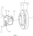
FIG. 2 is a schematic structural diagram of a first end and a first side wall of a brush in a separated state according to an embodiment of the present application; -
FIG. 3 is a schematic structural diagram of a first end of a brush in a separated state according to an embodiment of the present application; -
FIG. 4 is a schematic structural diagram of a first end and a first side wall of a brush in a separated state from another perspective according to an embodiment of the present application; -
FIG. 5 is a schematic structural diagram of a second end of a brush in a separated state according to an embodiment of the present application; -
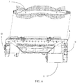
FIG. 6 is an overall schematic structural diagram of a brush member according to an embodiment of the present application; -
FIG. 7 is an overall schematic structural diagram of a robot according to an embodiment of the present application; and -
FIG. 8 is an overall structural block diagram of a robot according to an embodiment of the present application. - The following further describes embodiments of the present application in detail with reference to accompanying drawings. Clearly, the described embodiments are merely some rather than all of the embodiments of the present application. All other embodiments obtained by persons of ordinary skill in the art based on the embodiments of the present application without creative efforts shall fall within the protection scope of the present application.
- The terms used in the embodiments of the present application are merely for the purpose of illustrating specific embodiments, and are not intended to limit the present application. The terms "a", "the", and "this" of singular forms used in the embodiments and the appended claims of the present application are also intended to include plural forms, unless otherwise specified in the context clearly. "A plurality of" generally includes at least two.
- It should be understood that, the term "and/or" in this specification describes only an association relationship for describing associated objects and represents that three relationships may exist. For example, A and/or B may represent the following three cases: Only A exists, both A and B exist, and only B exists. In addition, the character "/" in this specification generally indicates an "or" relationship between associated objects.
- It should be understood that, although terms such as "first", "second", and "third" may be used in embodiments of the present application to describe components, the components should not be limited by these terms. These terms are merely used to distinguish between the similar objects. For example, without departing from the scope of the embodiments of the present application, a first component may also be referred to as a second component, and similarly, the second component may also be referred to as the first component.
- Depending on the context, for example, the word "if" used herein may be explained as "while" or "when" or "in response to determining" or "in response to detection". Similarly, depending on the context, the phrase "if determining" or "if detecting (a stated condition or event)" may be explained as "when determining" or "in response to determining" or "when detecting (the stated condition or event)" or "in response to detecting (the stated condition or event)".
- It should further be noted that, the terms "include", "comprise", or any other variant thereof are intended to cover a non-exclusive inclusion, so that a product or a system that includes a list of elements not only includes those elements but also includes other elements that are not expressly listed, or further includes elements inherent to such a product or system. An element preceded by "includes a ..." does not, without more constraints, preclude the existence of additional identical elements in the product or system that includes the element.
- The following describes in detail some example embodiments of the present application with reference to the accompanying drawings.
- As shown in
FIG. 1 , based on an implementation of the present application, according to a first aspect, an embodiment of the present application provides a brush applied to a cleaning robot. The brush includes abrush body 1 and thebrush body 1 includes arotating shaft 11. The rotatingshaft 11 is connected to a motor 5 (as shown inFIG. 6 ) and rotates under driving of the motor, and therotating shaft 11 may have a hollow or solid structure. Thebrush body 1 further includesbristles 12, which are distributed around the rotatingshaft 11 regularly. For example, a structure of 3-5 rows of bristles parallel to the rotating shaft or a wavy structure of 3-5 rows of bristles may be employed. The number of rows of bristles can be reasonably designed based on a size of the rotating shaft and is not limited separately herein. The bristles can be made of plastic or other polymer materials. A soft rubber scraping strip may be arranged between rows of the bristles. The scraping strip can increase negative pressure of a dust suction duct during operation of a cleaning robot, thereby improving dust pick up efficiency (DPU) of the cleaning device. Thebrush body 1 further includes afirst end portion 13 and asecond end portion 14, and thefirst end portion 13 and thesecond end portion 14 are respectively located at two ends of therotating shaft 11. The brush further includes two detachable baffles: a firstdetachable baffle 2 detachably mounted on thefirst end portion 13; a seconddetachable baffle 3 detachably mounted on thesecond end portion 14. Thefirst end portion 13 may be further provided with afoolproof structure 131 for preventing missing mounting of the firstdetachable baffle 2. In the embodiments of the present application, the two detachable baffles may have the same structure, and may be round, or may be square or other shapes, as shown inFIG. 1 or FIG. 2 . - Optionally, as shown in
FIG. 2 orFIG. 3 , in some implementations, thefirst end portion 13 may include a first mountingportion 132 and a second mountingportion 133. The first mountingportion 132 may generally have a cylindrical structure with a diameter slightly smaller than a diameter of therotating shaft 11 and may be formed through extension along the rotatingshaft 11. Thesecond mounting portion 133 extends outward along the first mountingportion 132 and forms a step with the first mountingportion 132. Thesecond mounting portion 133 preferably has a square structure with a side length smaller than the diameter of the first mountingportion 132 That is, two steps are formed outward from the rotating shaft. The first mountingportion 132 is configured to match the shape of the firstdetachable baffle 2, and the second mountingportion 133 is configured to match a structure of afirst side wall 41 of a member housing 4. The first end portion of the rotating shaft can be properly mounted to the member housing 4 when the shapes and sizes match. - Optionally, as shown in
FIG. 3 orFIG. 4 , in some implementations, thefoolproof structure 131 may include agroove 1311, which may penetrate or not penetrate the first mountingportion 132 and the second mountingportion 133 laterally, and may penetrate the first mountingportion 132 and the second mountingportion 133 axially. The axial direction is a direction extending along the rotatingshaft 11, and the lateral direction is a direction perpendicular to the axial direction. Thefoolproof mounting structure 131 further includes at least oneclamping part 1312, which is displaceably mounted in thegroove 1311. In some implementations, there may be one or two clampingparts 1312. Thefoolproof mounting structure 131 further includes anelastic element 1313, which is connected to theclamping part 1312 to make theclamping part 1312 retract into or extend out of thegroove 1311. Theelastic element 1313 may be a helical spring or an elastic sheet, etc. - Optionally, in an implementation (not shown), the
groove 1311 does not penetrate the first mountingportion 132 and the second mountingportion 133 laterally. That is, thegroove 1311 is a structure similar to a blind hole laterally in the first mountingportion 132 and the second mountingportion 133. In this case, there is oneclamping part 1312. One end of theelastic element 1313 is connected to theclamping part 1312, and the other end of theelastic element 1313 abuts against the bottom of thegroove 1311. In this implementation, theclamping part 1312 achieves elastic extending and retraction on the side of the first mountingportion 132 and the second mountingportion 133. - Optionally, in an implementation, as shown in
FIG. 4 , thegroove 1311 penetrates the first mountingportion 132 and the second mountingportion 133 laterally; there are two clampingparts 1312, which are symmetrically arranged on both sides of thegroove 1311; theelastic element 1313 connects the two clampingparts 1312. The clampingparts 1312 achieves elastic extending and retraction on both sides of the first mountingportion 132 and the second mountingportion 133 respectively. - Optionally, in some implementations, as shown in
FIG. 4 , theclamping part 1312 includes at least one first protrusion, shown as one protrusion, which is arranged at an outer side of the front portion of theclamping part 1312, and the first protrusion is configured to abut against an inner side of the firstdetachable baffle 2. Theclamping part 1312 further includes a second protrusion, which is arranged on the same side as the first protrusion, as shown in the figures, arranged at the rear of the first protrusion. When the firstdetachable baffle 2 is mounted on the brush, the second protrusion retracts into the groove. Specifically, when the inner side of the firstdetachable baffle 2 presses the first protrusion, to make theclamping part 1312 retract into thegroove 1311. Consequently, the second protrusion retracts into thegroove 1311, which ensures that the second mountingportion 133 can match and extend into thefirst side wall 41 of the member housing 4 smoothly to achieve successful mounting of the brush. On the contrary, when the firstdetachable baffle 2 is not mounted on the brush, theclamping part 1312 extends out of thegroove 1311, consequently, the second protrusion is out of the groove, the second mountingportion 133 cannot extend into thefirst side wall 41 of the member housing 4, and the brush cannot be successfully mounted on the member housing. As a result, the purpose of foolproof can be achieved. - The
clamping part 1312 may further include at least one third protrusion, which is arranged on the inner side of theclamping part 1312 and is configured to connect to theelastic element 1313. - Optionally, in some implementations, as shown in
FIG. 3 , the first mountingportion 132 further includes at least onefirst locking portion 1321; the inner side of the firstdetachable baffle 2 includes at least onefirst locking block 21 corresponding to thefirst locking portion 1321. When the firstdetachable baffle 2 is mounted on thefirst end portion 13, thefirst locking block 21 slides into thefirst locking portion 1321 to achieve locking. Optionally, thefirst locking portion 1321 may have an L-shaped sliding groove structure. When entering thefirst locking portion 1321 from an entrance of the L-shaped sliding groove, thefirst locking block 21 rotates at a specific angle in a circumferential direction of the first mountingportion 132, so that thefirst locking block 21 slides into a lateral position of the L-shaped sliding groove to achieve locking. - Optionally, in other implementations, the
first locking portion 1321 may alternatively have a spherical recess structure, and thefirst locking block 21 has a hemispherical protrusion structure. When the firstdetachable baffle 2 is axially mounted to the first mountingportion 132, the hemisphericalfirst locking block 21 slides into the spherical recess in the axial direction to achieve locking. - Optionally, in some implementations, as shown in
FIG. 3 orFIG. 4 , the firstdetachable baffle 2 includes afirst aperture 22, an inner diameter of which matches an outer diameter of the first mountingportion 132, and an axial size of which matches an axial size of the first mountingportion 132. The firstdetachable baffle 2 is mounted to the first mountingportion 132 by the first mountingportion 132 extending into thefirst aperture 22. The firstdetachable baffle 2 further includes asecond aperture 23, which extends upward and outward along thefirst aperture 22, has an inner diameter larger than the inner diameter of thefirst aperture 22, and is configured to cooperate with the side wall structure to achieve stable mounting. The firstdetachable baffle 2 further includes afirst baffle portion 24, which extends outward in the circumferential direction of thefirst aperture 22, has a diameter equivalent to an outer diameter of thesecond aperture 23, and is configured to prevent hair from entering the baffle. - Optionally, as shown in
FIG. 5 , in some implementations, thesecond end portion 14 may include a third mountingportion 141 and a fourth mountingportion 142. Thethird mounting portion 141 may generally have a cylindrical structure with a diameter slightly smaller than a diameter of therotating shaft 11 and may be formed through extension along the rotatingshaft 11. The fourth mountingportion 142 extends outward along the third mountingportion 141 and forms a step with the third mountingportion 141. The fourth mountingportion 142 preferably has a round structure with a diameter smaller than the diameter of the third mountingportion 141, that is, a continuous step portion is formed outward from the rotating shaft. Thethird mounting portion 141 is mainly configured to match the shape of the seconddetachable baffle 3, and the fourth mountingportion 142 is mainly configured to match a structure of a joint 145. The second end portion of the rotating shaft can be properly mounted to the member housing 4 when the shapes and sizes match. Thesecond end portion 14 may include ashaft portion 143 for extending into the joint 145 and then rotating. - Optionally, in some implementations, as shown in
FIG. 5 , the third mountingportion 141 further includes at least onesecond locking portion 144; the inner side of the seconddetachable baffle 3 includes at least onesecond locking block 31 corresponding to thesecond locking portion 144, and when the seconddetachable baffle 3 is mounted on thesecond end portion 14, thesecond locking block 31 slides into thesecond locking portion 144 to achieve locking. Optionally, thesecond locking portion 144 may have an L-shaped sliding groove structure. After entering thesecond locking portion 144 from an entrance of the L-shaped sliding groove, thesecond locking block 31 rotates at a specific angle in a circumferential direction of the third mountingportion 141, so that thesecond locking block 31 slides into a lateral position of the L-shaped sliding groove to achieve locking. - Optionally, in other implementations, the
second locking portion 144 may alternatively have a spherical recess structure, and thesecond locking block 31 has a hemispherical protrusion structure. When the seconddetachable baffle 3 is axially mounted to the third mountingportion 141, the hemisphericalsecond locking block 31 slides into the spherical recess in the axial direction to achieve locking. - Optionally, in some implementations, as shown in
FIG. 5 , the seconddetachable baffle 3 includes athird aperture 32, an inner diameter of which matches an outer diameter of the third mountingportion 141, and an axial size of which matches an axial size of the third mountingportion 141. The seconddetachable baffle 3 is mounted to the third mountingportion 141 by the third mountingportion 141 extending into thethird aperture 32. The seconddetachable baffle 3 further includes afourth aperture 33, which extends upward and outward along thethird aperture 32, has an inner diameter larger than the inner diameter of thethird aperture 32, and is configured to cooperate with the side wall structure to achieve stable mounting. The seconddetachable baffle 3 further includes asecond baffle portion 24, which extends outward in the circumferential direction of thethird aperture 32, has a diameter equivalent to an outer diameter of thefourth aperture 33, and is configured to prevent hair from entering the baffle. - Optionally, in some implementations, as shown in
FIG. 5 , a joint 145 is further included, which has a threaded structure and is configured to be fixed to thesecond side wall 42 in a threaded manner. When thefirst end portion 13 and thesecond end portion 14 are respectively mounted on thefirst side wall 41 and thesecond side wall 42, the mounting of the brush body is completed. - According to the brush provided in the embodiments of the present application, addition of a detachable baffle can effectively prevent hair on the brush of the cleaning robot from entering the motor, and the design of the foolproof structure can effectively prevent a user from missing a detachable baffle, and further prevent hair and other objects from entering the driving motor of the main brush, thereby preventing damage to the motor.
- As shown in
FIG. 6 , based on an implementation of the present application, according to a second aspect, an embodiment of the present application provides a brush member, including a member housing 4 and the brush described inEmbodiment 1. The structure of the brush has been described above, and details are not described herein again. - Optionally, in some implementations, as shown in
FIG. 2 orFIG. 4 , the member housing 4 includes afirst side wall 41 for connecting to thefirst end portion 13, and thefirst side wall 41 includes afirst accommodation hole 411 for accommodating the second mountingportion 133 of thefirst end portion 13. Thefirst accommodation hole 411 may be a square blind hole with a depth slightly greater than an axial length of the second mountingportion 133. Thefirst side wall 41 may further include a firstannular groove 412, which is arranged around thefirst accommodation hole 411, and is configured to accommodate a side wall of thesecond aperture 23 of the firstdetachable baffle 2. The depth of the firstannular groove 412 may be sufficient to accommodate the side wall of thesecond aperture 23. - The member housing 4 further includes a
second side wall 42, which is configured to connect to thesecond end portion 14. Thesecond side wall 42 may include an internally threaded hole, which is configured to be fixed and connected to the threaded joint 145. - According to the brush member provided in the embodiments of the present application, addition of a detachable baffle can effectively prevent hair on the brush of the cleaning robot from entering the motor, and the design of the foolproof structure can effectively prevent a user from missing a detachable baffle, and further prevent hair and other objects from entering the driving motor of the main brush, thereby preventing damage to the motor.
- As shown in
FIG. 7 , based on an implementation of the present application, according to a third aspect, an embodiment of the present application provides a cleaning robot, including a drivingpart 5 and the brush member described inEmbodiment 1 andEmbodiment 2. The structures of the brush and member have been described above, and details are not described herein again. - As shown in
FIG. 8 , the robot includes a machine body, a perception system, a control system, a driving system, a cleaning system, an energy system, and a man-machine interaction system. The cleaning system may be a dry cleaning system and/or a wet cleaning system. The main cleaning function of the dry cleaning system is derived from a sweeping system that includes a brush, a dust box, a vacuum, an air outlet, and connecting parts between the four parts. The brush that has interference with the floor sweeps debris on the floor and agitates the debris to the front of a dust suction port between the brush and the dust box, and then the debris is sucked into the dust box by airflow that is generated by the vacuum and that has suction force and passes through the dust box. The dust removal ability of the sweeping robot may be represented by dust pick up efficiency (DPU). The DPU is affected by the brush structure and a material thereof, by wind power utilization of an air duct including the dust suction port, the dust box, the vacuum, the air outlet, and the connecting parts between the four parts, and by the type and power of the vacuum, and therefore, there is a complex system design problem. The increase in the dust removal ability is more significant for energy-limited cleaning robots than for conventional plug-in cleaners. A higher dust-removal ability directly and effectively reduces the energy requirement; in other words, a machine that can clean 80 square meters of the floor previously after being charged once can be evolved to clean 100 or more square meters of the floor after being charged once. - Moreover, as charging times decrease, the service life of a battery increases greatly, so that the frequency of replacing the battery by the user decreases. More intuitively and importantly, a higher dust-removal ability is the most visible and important user experience, because it allows the user to directly determine whether the floor is swept/wiped clean. The dry cleaning system may further include a side brush having a rotating shaft. The rotating shaft is located at an angle relative to the floor, so as to move debris into a region of the rolling brush of the cleaning system.
- According to the robot provided in the embodiments of the present application, the addition of a detachable baffle can effectively prevent hair on the brush of the cleaning robot from entering the motor, and the design of the foolproof structure can effectively prevent a user from missing a detachable baffle, and further prevent hair and other objects from entering the driving motor of the main brush, thereby preventing damage to the motor.
- The described apparatus embodiments are merely examples. The units described as separate parts may or may not be physically separate, and parts displayed as units may or may not be physical units, may be located in one position, or may be distributed on a plurality of network units. Some or all the modules may be selected according to actual needs to achieve the objectives of the solutions of the embodiments.
- Finally, it should be noted that the foregoing embodiments are merely intended for describing the technical solutions in some embodiments of the present application, but not for limiting the present application. Although the present application is described in detail with reference to the foregoing embodiments, persons of ordinary skill in the art should understand that they may still make modifications to the technical solutions described in the foregoing embodiments or make equivalent replacements to some technical features thereof, without departing from the spirit and scope of the technical solutions of the embodiments of the present application.
Claims (14)
- A brush, applied to a cleaning robot, comprising:a brush body, comprising:a rotating shaft having a first end portion and a second end portion;bristles;a first detachable baffle detachably mounted to the first end portion; anda second detachable baffle detachably mounted to the second end portion, whereinthe first end portion is provided with a foolproof structure for preventing missing mounting of the first detachable baffle.
- The brush according to claim 1, wherein the first end portion comprises:a first mounting portion; anda second mounting portion, disposed to extend axially from the first mounting portion and form a step portion with the first mounting portion.
- The brush according to claim 2, wherein the foolproof structure comprises:a groove, which penetrates or does not penetrate the first mounting portion and the second mounting portion laterally, and penetrates the first mounting portion and the second mounting portion axially;an elastic element mounted in the groove; anda clamping part, which is mounted in the groove, and configured to retract into or extend out of the groove through a connection with the elastic element.
- The brush according to claim 3, wherein the groove does not penetrate the first mounting portion and the second mounting portion laterally; one end of the elastic element is connected to the clamping part, and the other end of the elastic element abuts against a bottom of the groove.
- The brush according to claim 3, wherein the groove penetrates the first mounting portion and the second mounting portion laterally;
wherein two clamping parts are symmetrically arranged on two ends of the groove and connected to the elastic element. - The brush according to claim 3, wherein the clamping part comprises:at least one first protrusion, which is arranged on an outer side of the clamping part for abutting against an inner side of the first detachable baffle; anda second protrusion, which is arranged on the same side as the first protrusion, wherein when the first detachable baffle is mounted on the brush, the second protrusion retracts into the groove.
- The brush according to claim 3, wherein the first mounting portion further comprises at least one locking portion; an inner side of the first detachable baffle comprises at least one locking block corresponding to the locking portion, and after the first detachable baffle is mounted on the first end portion, the locking block slides into the locking portion to achieve locking.
- The brush according to claim 7, wherein the locking portion has an L-shaped sliding groove structure.
- The brush according to claim 7, wherein the locking portion has a spherical recess structure, and the locking block has a hemispherical protrusion structure.
- The brush according to claim 2, wherein the second mounting portion has a square structure.
- The brush according to claim 2, wherein the first detachable baffle comprises:a first aperture, an inner diameter of which matches an outer diameter of the first mounting portion, and an axial size of which matches an axial size of the first mounting portion;a second aperture, which extends along the first aperture and has an inner diameter larger than the inner diameter of the first aperture; anda baffle portion, which extends outward along a circumferential direction of the first aperture, and has a diameter equivalent to an outer diameter of the second aperture.
- A brush member, comprising a member housing and the robot-specific brush according to any one of claims 1 to 11.
- The brush member according to claim 12, wherein the member housing comprises:
a first side wall, configured to connect to the first end portion, comprising:a first accommodation hole, configured to accommodate the first end portion; anda first annular groove, configured to accommodate the first detachable baffle; anda second side wall, configured to connect to the second end portion. - A robot, comprising the robot-specific brush member according to either of claims 12 and 13.
Applications Claiming Priority (2)
| Application Number | Priority Date | Filing Date | Title |
|---|---|---|---|
| CN201920126884.3U CN210383784U (en) | 2019-01-24 | 2019-01-24 | Robot brush, component and robot |
| PCT/CN2020/072630 WO2020151582A1 (en) | 2019-01-24 | 2020-01-17 | Brush and component for robot, and robot |
Publications (4)
| Publication Number | Publication Date |
|---|---|
| EP3912540A1 true EP3912540A1 (en) | 2021-11-24 |
| EP3912540A4 EP3912540A4 (en) | 2022-11-02 |
| EP3912540C0 EP3912540C0 (en) | 2025-06-04 |
| EP3912540B1 EP3912540B1 (en) | 2025-06-04 |
Family
ID=70336879
Family Applications (1)
| Application Number | Title | Priority Date | Filing Date |
|---|---|---|---|
| EP20745484.4A Active EP3912540B1 (en) | 2019-01-24 | 2020-01-17 | Brush and component for robot, and robot |
Country Status (5)
| Country | Link |
|---|---|
| US (1) | US12622558B2 (en) |
| EP (1) | EP3912540B1 (en) |
| CN (1) | CN210383784U (en) |
| ES (1) | ES3039976T3 (en) |
| WO (1) | WO2020151582A1 (en) |
Families Citing this family (2)
| Publication number | Priority date | Publication date | Assignee | Title |
|---|---|---|---|---|
| CN115886650B (en) * | 2021-09-30 | 2025-12-19 | 苏州普发科技有限公司 | Detachable brush roller assembly |
| CN116712003A (en) * | 2023-07-20 | 2023-09-08 | 上海高仙自动化科技发展有限公司 | Roller brush cleaning mechanism and intelligent cleaning robot |
Family Cites Families (26)
| Publication number | Priority date | Publication date | Assignee | Title |
|---|---|---|---|---|
| GB1109783A (en) * | 1964-07-16 | 1968-04-18 | Westinghouse Electric Corp | An agitator roll assembly for a suction cleaner |
| DE2728992A1 (en) * | 1977-06-28 | 1979-01-18 | Duepro Ag | CLEANING DEVICE |
| US4429430A (en) * | 1982-01-11 | 1984-02-07 | Whirlpool Corporation | Vacuum cleaner beater brush structure |
| US4912805A (en) * | 1988-07-13 | 1990-04-03 | Black & Decker Inc. | Dual-purpose rotating brush for vacuum cleaner |
| US5465451A (en) * | 1989-12-26 | 1995-11-14 | The Scott Fetzer Company | Brushroll |
| JP2596223Y2 (en) * | 1992-09-30 | 1999-06-07 | 東芝テック株式会社 | Vacuum cleaner suction body |
| JP3424143B2 (en) * | 1995-10-05 | 2003-07-07 | 三菱電機株式会社 | Vacuum cleaner suction tool |
| DE19820628C1 (en) * | 1998-05-08 | 1999-09-23 | Kaercher Gmbh & Co Alfred | Roller mounting or carpet sweeper |
| JP2003052585A (en) * | 2001-08-20 | 2003-02-25 | Toshiba Tec Corp | Rotary cleaning body, suction port provided with the same, and vacuum cleaner provided with the suction port |
| US8528157B2 (en) * | 2006-05-19 | 2013-09-10 | Irobot Corporation | Coverage robots and associated cleaning bins |
| WO2008091199A1 (en) * | 2007-01-23 | 2008-07-31 | Aktiebolaget Electrolux | Vacuum cleaner nozzle |
| WO2011017765A1 (en) * | 2009-08-14 | 2011-02-17 | Yalbaton Pty Ltd | A bar coupler |
| KR101497197B1 (en) * | 2010-02-16 | 2015-02-27 | 아이로보트 코퍼레이션 | Vacuum brush |
| US8826493B2 (en) * | 2011-02-15 | 2014-09-09 | The Scott-Fetzer Company | Vacuum cleaner brushroll |
| KR101932080B1 (en) * | 2012-03-08 | 2018-12-24 | 엘지전자 주식회사 | Agitator and cleaner comprising the same |
| RU2015122397A (en) * | 2012-12-11 | 2017-01-10 | Роберт РАССЕЛЛ | ADVANCED SHAFT CONNECTOR |
| US10077791B2 (en) * | 2013-06-10 | 2018-09-18 | David W. Kresge | Coupling device |
| US10398275B2 (en) * | 2014-05-23 | 2019-09-03 | Lg Electronics Inc. | Robot cleaner |
| US10288123B2 (en) * | 2014-06-26 | 2019-05-14 | Gregory Lee Newth | Shaft coupler |
| CN204120958U (en) * | 2014-10-10 | 2015-01-28 | 深圳市银星智能科技股份有限公司 | The antiwind structure of a kind of cleaning brush for clean robot |
| CN204618100U (en) * | 2015-03-27 | 2015-09-09 | 苏州凯丽达电器有限公司 | Dust catcher filter assemblies leakproof assembling structure |
| CN205234411U (en) * | 2015-04-15 | 2016-05-18 | 小米科技有限责任公司 | Round brush transmission and dust collector |
| CN105982623B (en) * | 2016-04-14 | 2019-08-02 | 北京小米移动软件有限公司 | Roller brush assembly, air path structure and automatic cleaning equipment of automatic cleaning equipment |
| CN105982625B (en) * | 2016-04-14 | 2019-07-09 | 北京小米移动软件有限公司 | Automatic cleaning equipment and its cleaning components |
| CN205970630U (en) * | 2016-07-29 | 2017-02-22 | 北京小米移动软件有限公司 | Roller module and cleaning robot |
| CN106901659B (en) * | 2017-02-25 | 2018-06-01 | 广东宝乐机器人股份有限公司 | Clean robot |
-
2019
- 2019-01-24 CN CN201920126884.3U patent/CN210383784U/en active Active
-
2020
- 2020-01-17 EP EP20745484.4A patent/EP3912540B1/en active Active
- 2020-01-17 ES ES20745484T patent/ES3039976T3/en active Active
- 2020-01-17 WO PCT/CN2020/072630 patent/WO2020151582A1/en not_active Ceased
-
2021
- 2021-07-23 US US17/383,535 patent/US12622558B2/en active Active
Also Published As
| Publication number | Publication date |
|---|---|
| EP3912540A4 (en) | 2022-11-02 |
| US12622558B2 (en) | 2026-05-12 |
| EP3912540C0 (en) | 2025-06-04 |
| EP3912540B1 (en) | 2025-06-04 |
| CN210383784U (en) | 2020-04-24 |
| ES3039976T3 (en) | 2025-10-28 |
| WO2020151582A1 (en) | 2020-07-30 |
| US20210345850A1 (en) | 2021-11-11 |
Similar Documents
| Publication | Publication Date | Title |
|---|---|---|
| EP2941994B1 (en) | Vacuum cleaner | |
| EP3666147B1 (en) | Docking station | |
| US12622558B2 (en) | Brush, brush member and robot | |
| CN219680482U (en) | Automatic cleaning equipment | |
| WO2024139317A1 (en) | Automatic cleaning device | |
| JP3253886U (en) | Automatic Cleaning Device | |
| TWI856874B (en) | Cleaning module and cleaning device |
Legal Events
| Date | Code | Title | Description |
|---|---|---|---|
| STAA | Information on the status of an ep patent application or granted ep patent |
Free format text: STATUS: THE INTERNATIONAL PUBLICATION HAS BEEN MADE |
|
| PUAI | Public reference made under article 153(3) epc to a published international application that has entered the european phase |
Free format text: ORIGINAL CODE: 0009012 |
|
| STAA | Information on the status of an ep patent application or granted ep patent |
Free format text: STATUS: REQUEST FOR EXAMINATION WAS MADE |
|
| 17P | Request for examination filed |
Effective date: 20210820 |
|
| AK | Designated contracting states |
Kind code of ref document: A1 Designated state(s): AL AT BE BG CH CY CZ DE DK EE ES FI FR GB GR HR HU IE IS IT LI LT LU LV MC MK MT NL NO PL PT RO RS SE SI SK SM TR |
|
| DAV | Request for validation of the european patent (deleted) | ||
| DAX | Request for extension of the european patent (deleted) | ||
| A4 | Supplementary search report drawn up and despatched |
Effective date: 20220929 |
|
| RIC1 | Information provided on ipc code assigned before grant |
Ipc: A47L 11/40 20060101AFI20220923BHEP |
|
| GRAP | Despatch of communication of intention to grant a patent |
Free format text: ORIGINAL CODE: EPIDOSNIGR1 |
|
| STAA | Information on the status of an ep patent application or granted ep patent |
Free format text: STATUS: GRANT OF PATENT IS INTENDED |
|
| INTG | Intention to grant announced |
Effective date: 20250102 |
|
| GRAS | Grant fee paid |
Free format text: ORIGINAL CODE: EPIDOSNIGR3 |
|
| GRAA | (expected) grant |
Free format text: ORIGINAL CODE: 0009210 |
|
| STAA | Information on the status of an ep patent application or granted ep patent |
Free format text: STATUS: THE PATENT HAS BEEN GRANTED |
|
| AK | Designated contracting states |
Kind code of ref document: B1 Designated state(s): AL AT BE BG CH CY CZ DE DK EE ES FI FR GB GR HR HU IE IS IT LI LT LU LV MC MK MT NL NO PL PT RO RS SE SI SK SM TR |
|
| REG | Reference to a national code |
Ref country code: GB Ref legal event code: FG4D |
|
| REG | Reference to a national code |
Ref country code: CH Ref legal event code: EP |
|
| REG | Reference to a national code |
Ref country code: DE Ref legal event code: R096 Ref document number: 602020052298 Country of ref document: DE |
|
| REG | Reference to a national code |
Ref country code: IE Ref legal event code: FG4D |
|
| U01 | Request for unitary effect filed |
Effective date: 20250624 |
|
| U07 | Unitary effect registered |
Designated state(s): AT BE BG DE DK EE FI FR IT LT LU LV MT NL PT RO SE SI Effective date: 20250701 |
|
| PG25 | Lapsed in a contracting state [announced via postgrant information from national office to epo] |
Ref country code: GR Free format text: LAPSE BECAUSE OF FAILURE TO SUBMIT A TRANSLATION OF THE DESCRIPTION OR TO PAY THE FEE WITHIN THE PRESCRIBED TIME-LIMIT Effective date: 20250905 |
|
| PG25 | Lapsed in a contracting state [announced via postgrant information from national office to epo] |
Ref country code: PL Free format text: LAPSE BECAUSE OF FAILURE TO SUBMIT A TRANSLATION OF THE DESCRIPTION OR TO PAY THE FEE WITHIN THE PRESCRIBED TIME-LIMIT Effective date: 20250604 |
|
| PG25 | Lapsed in a contracting state [announced via postgrant information from national office to epo] |
Ref country code: HR Free format text: LAPSE BECAUSE OF FAILURE TO SUBMIT A TRANSLATION OF THE DESCRIPTION OR TO PAY THE FEE WITHIN THE PRESCRIBED TIME-LIMIT Effective date: 20250604 |
|
| PG25 | Lapsed in a contracting state [announced via postgrant information from national office to epo] |
Ref country code: RS Free format text: LAPSE BECAUSE OF FAILURE TO SUBMIT A TRANSLATION OF THE DESCRIPTION OR TO PAY THE FEE WITHIN THE PRESCRIBED TIME-LIMIT Effective date: 20250904 |
|
| REG | Reference to a national code |
Ref country code: ES Ref legal event code: FG2A Ref document number: 3039976 Country of ref document: ES Kind code of ref document: T3 Effective date: 20251028 |
|
| U1N | Appointed representative for the unitary patent procedure changed after the registration of the unitary effect |
Representative=s name: LORENZ SEIDLER GOSSEL PART. MBB; DE |
|
| PG25 | Lapsed in a contracting state [announced via postgrant information from national office to epo] |
Ref country code: IS Free format text: LAPSE BECAUSE OF FAILURE TO SUBMIT A TRANSLATION OF THE DESCRIPTION OR TO PAY THE FEE WITHIN THE PRESCRIBED TIME-LIMIT Effective date: 20251004 |
|
| PG25 | Lapsed in a contracting state [announced via postgrant information from national office to epo] |
Ref country code: SM Free format text: LAPSE BECAUSE OF FAILURE TO SUBMIT A TRANSLATION OF THE DESCRIPTION OR TO PAY THE FEE WITHIN THE PRESCRIBED TIME-LIMIT Effective date: 20250604 |
|
| PG25 | Lapsed in a contracting state [announced via postgrant information from national office to epo] |
Ref country code: CZ Free format text: LAPSE BECAUSE OF FAILURE TO SUBMIT A TRANSLATION OF THE DESCRIPTION OR TO PAY THE FEE WITHIN THE PRESCRIBED TIME-LIMIT Effective date: 20250604 |
|
| PG25 | Lapsed in a contracting state [announced via postgrant information from national office to epo] |
Ref country code: SK Free format text: LAPSE BECAUSE OF FAILURE TO SUBMIT A TRANSLATION OF THE DESCRIPTION OR TO PAY THE FEE WITHIN THE PRESCRIBED TIME-LIMIT Effective date: 20250604 |
|
| U20 | Renewal fee for the european patent with unitary effect paid |
Year of fee payment: 7 Effective date: 20260128 |
|
| PGFP | Annual fee paid to national office [announced via postgrant information from national office to epo] |
Ref country code: GB Payment date: 20260121 Year of fee payment: 7 |
|
| PGFP | Annual fee paid to national office [announced via postgrant information from national office to epo] |
Ref country code: ES Payment date: 20260202 Year of fee payment: 7 |
|
| PLBE | No opposition filed within time limit |
Free format text: ORIGINAL CODE: 0009261 |
|
| STAA | Information on the status of an ep patent application or granted ep patent |
Free format text: STATUS: NO OPPOSITION FILED WITHIN TIME LIMIT |
|
| PGFP | Annual fee paid to national office [announced via postgrant information from national office to epo] |
Ref country code: NO Payment date: 20260127 Year of fee payment: 7 |
|
| REG | Reference to a national code |
Ref country code: CH Ref legal event code: L10 Free format text: ST27 STATUS EVENT CODE: U-0-0-L10-L00 (AS PROVIDED BY THE NATIONAL OFFICE) Effective date: 20260416 |
|
| PGFP | Annual fee paid to national office [announced via postgrant information from national office to epo] |
Ref country code: TR Payment date: 20260107 Year of fee payment: 7 |
|
| 26N | No opposition filed |
Effective date: 20260305 |